EP4074536A2 - Glasfaserbasiertes sensormembran-layout - Google Patents
Glasfaserbasiertes sensormembran-layout Download PDFInfo
- Publication number
- EP4074536A2 EP4074536A2 EP22167553.1A EP22167553A EP4074536A2 EP 4074536 A2 EP4074536 A2 EP 4074536A2 EP 22167553 A EP22167553 A EP 22167553A EP 4074536 A2 EP4074536 A2 EP 4074536A2
- Authority
- EP
- European Patent Office
- Prior art keywords
- optical fiber
- sensing membrane
- based sensing
- layout
- geometric pattern
- Prior art date
- Legal status (The legal status is an assumption and is not a legal conclusion. Google has not performed a legal analysis and makes no representation as to the accuracy of the status listed.)
- Granted
Links
Images


Classifications
-
- G—PHYSICS
- G01—MEASURING; TESTING
- G01D—MEASURING NOT SPECIALLY ADAPTED FOR A SPECIFIC VARIABLE; ARRANGEMENTS FOR MEASURING TWO OR MORE VARIABLES NOT COVERED IN A SINGLE OTHER SUBCLASS; TARIFF METERING APPARATUS; MEASURING OR TESTING NOT OTHERWISE PROVIDED FOR
- G01D5/00—Mechanical means for transferring the output of a sensing member; Means for converting the output of a sensing member to another variable where the form or nature of the sensing member does not constrain the means for converting; Transducers not specially adapted for a specific variable
- G01D5/26—Mechanical means for transferring the output of a sensing member; Means for converting the output of a sensing member to another variable where the form or nature of the sensing member does not constrain the means for converting; Transducers not specially adapted for a specific variable characterised by optical transfer means, i.e. using infrared, visible, or ultraviolet light
- G01D5/32—Mechanical means for transferring the output of a sensing member; Means for converting the output of a sensing member to another variable where the form or nature of the sensing member does not constrain the means for converting; Transducers not specially adapted for a specific variable characterised by optical transfer means, i.e. using infrared, visible, or ultraviolet light with attenuation or whole or partial obturation of beams of light
- G01D5/34—Mechanical means for transferring the output of a sensing member; Means for converting the output of a sensing member to another variable where the form or nature of the sensing member does not constrain the means for converting; Transducers not specially adapted for a specific variable characterised by optical transfer means, i.e. using infrared, visible, or ultraviolet light with attenuation or whole or partial obturation of beams of light the beams of light being detected by photocells
- G01D5/353—Mechanical means for transferring the output of a sensing member; Means for converting the output of a sensing member to another variable where the form or nature of the sensing member does not constrain the means for converting; Transducers not specially adapted for a specific variable characterised by optical transfer means, i.e. using infrared, visible, or ultraviolet light with attenuation or whole or partial obturation of beams of light the beams of light being detected by photocells influencing the transmission properties of an optical fibre
- G01D5/3537—Optical fibre sensor using a particular arrangement of the optical fibre itself
- G01D5/35374—Particular layout of the fiber
-
- B—PERFORMING OPERATIONS; TRANSPORTING
- B60—VEHICLES IN GENERAL
- B60L—PROPULSION OF ELECTRICALLY-PROPELLED VEHICLES; SUPPLYING ELECTRIC POWER FOR AUXILIARY EQUIPMENT OF ELECTRICALLY-PROPELLED VEHICLES; ELECTRODYNAMIC BRAKE SYSTEMS FOR VEHICLES IN GENERAL; MAGNETIC SUSPENSION OR LEVITATION FOR VEHICLES; MONITORING OPERATING VARIABLES OF ELECTRICALLY-PROPELLED VEHICLES; ELECTRIC SAFETY DEVICES FOR ELECTRICALLY-PROPELLED VEHICLES
- B60L50/00—Electric propulsion with power supplied within the vehicle
- B60L50/50—Electric propulsion with power supplied within the vehicle using propulsion power supplied by batteries or fuel cells
- B60L50/60—Electric propulsion with power supplied within the vehicle using propulsion power supplied by batteries or fuel cells using power supplied by batteries
- B60L50/64—Constructional details of batteries specially adapted for electric vehicles
-
- B—PERFORMING OPERATIONS; TRANSPORTING
- B60—VEHICLES IN GENERAL
- B60L—PROPULSION OF ELECTRICALLY-PROPELLED VEHICLES; SUPPLYING ELECTRIC POWER FOR AUXILIARY EQUIPMENT OF ELECTRICALLY-PROPELLED VEHICLES; ELECTRODYNAMIC BRAKE SYSTEMS FOR VEHICLES IN GENERAL; MAGNETIC SUSPENSION OR LEVITATION FOR VEHICLES; MONITORING OPERATING VARIABLES OF ELECTRICALLY-PROPELLED VEHICLES; ELECTRIC SAFETY DEVICES FOR ELECTRICALLY-PROPELLED VEHICLES
- B60L50/00—Electric propulsion with power supplied within the vehicle
- B60L50/50—Electric propulsion with power supplied within the vehicle using propulsion power supplied by batteries or fuel cells
- B60L50/60—Electric propulsion with power supplied within the vehicle using propulsion power supplied by batteries or fuel cells using power supplied by batteries
- B60L50/66—Arrangements of batteries
-
- B—PERFORMING OPERATIONS; TRANSPORTING
- B60—VEHICLES IN GENERAL
- B60L—PROPULSION OF ELECTRICALLY-PROPELLED VEHICLES; SUPPLYING ELECTRIC POWER FOR AUXILIARY EQUIPMENT OF ELECTRICALLY-PROPELLED VEHICLES; ELECTRODYNAMIC BRAKE SYSTEMS FOR VEHICLES IN GENERAL; MAGNETIC SUSPENSION OR LEVITATION FOR VEHICLES; MONITORING OPERATING VARIABLES OF ELECTRICALLY-PROPELLED VEHICLES; ELECTRIC SAFETY DEVICES FOR ELECTRICALLY-PROPELLED VEHICLES
- B60L58/00—Methods or circuit arrangements for monitoring or controlling batteries or fuel cells, specially adapted for electric vehicles
- B60L58/10—Methods or circuit arrangements for monitoring or controlling batteries or fuel cells, specially adapted for electric vehicles for monitoring or controlling batteries
- B60L58/18—Methods or circuit arrangements for monitoring or controlling batteries or fuel cells, specially adapted for electric vehicles for monitoring or controlling batteries of two or more battery modules
-
- G—PHYSICS
- G01—MEASURING; TESTING
- G01B—MEASURING LENGTH, THICKNESS OR SIMILAR LINEAR DIMENSIONS; MEASURING ANGLES; MEASURING AREAS; MEASURING IRREGULARITIES OF SURFACES OR CONTOURS
- G01B11/00—Measuring arrangements characterised by the use of optical techniques
- G01B11/16—Measuring arrangements characterised by the use of optical techniques for measuring the deformation in a solid, e.g. optical strain gauge
- G01B11/18—Measuring arrangements characterised by the use of optical techniques for measuring the deformation in a solid, e.g. optical strain gauge using photoelastic elements
-
- G—PHYSICS
- G01—MEASURING; TESTING
- G01D—MEASURING NOT SPECIALLY ADAPTED FOR A SPECIFIC VARIABLE; ARRANGEMENTS FOR MEASURING TWO OR MORE VARIABLES NOT COVERED IN A SINGLE OTHER SUBCLASS; TARIFF METERING APPARATUS; MEASURING OR TESTING NOT OTHERWISE PROVIDED FOR
- G01D21/00—Measuring or testing not otherwise provided for
- G01D21/02—Measuring two or more variables by means not covered by a single other subclass
-
- G—PHYSICS
- G01—MEASURING; TESTING
- G01D—MEASURING NOT SPECIALLY ADAPTED FOR A SPECIFIC VARIABLE; ARRANGEMENTS FOR MEASURING TWO OR MORE VARIABLES NOT COVERED IN A SINGLE OTHER SUBCLASS; TARIFF METERING APPARATUS; MEASURING OR TESTING NOT OTHERWISE PROVIDED FOR
- G01D5/00—Mechanical means for transferring the output of a sensing member; Means for converting the output of a sensing member to another variable where the form or nature of the sensing member does not constrain the means for converting; Transducers not specially adapted for a specific variable
- G01D5/26—Mechanical means for transferring the output of a sensing member; Means for converting the output of a sensing member to another variable where the form or nature of the sensing member does not constrain the means for converting; Transducers not specially adapted for a specific variable characterised by optical transfer means, i.e. using infrared, visible, or ultraviolet light
- G01D5/32—Mechanical means for transferring the output of a sensing member; Means for converting the output of a sensing member to another variable where the form or nature of the sensing member does not constrain the means for converting; Transducers not specially adapted for a specific variable characterised by optical transfer means, i.e. using infrared, visible, or ultraviolet light with attenuation or whole or partial obturation of beams of light
- G01D5/34—Mechanical means for transferring the output of a sensing member; Means for converting the output of a sensing member to another variable where the form or nature of the sensing member does not constrain the means for converting; Transducers not specially adapted for a specific variable characterised by optical transfer means, i.e. using infrared, visible, or ultraviolet light with attenuation or whole or partial obturation of beams of light the beams of light being detected by photocells
- G01D5/353—Mechanical means for transferring the output of a sensing member; Means for converting the output of a sensing member to another variable where the form or nature of the sensing member does not constrain the means for converting; Transducers not specially adapted for a specific variable characterised by optical transfer means, i.e. using infrared, visible, or ultraviolet light with attenuation or whole or partial obturation of beams of light the beams of light being detected by photocells influencing the transmission properties of an optical fibre
- G01D5/35338—Mechanical means for transferring the output of a sensing member; Means for converting the output of a sensing member to another variable where the form or nature of the sensing member does not constrain the means for converting; Transducers not specially adapted for a specific variable characterised by optical transfer means, i.e. using infrared, visible, or ultraviolet light with attenuation or whole or partial obturation of beams of light the beams of light being detected by photocells influencing the transmission properties of an optical fibre using other arrangements than interferometer arrangements
- G01D5/35354—Sensor working in reflection
- G01D5/35358—Sensor working in reflection using backscattering to detect the measured quantity
- G01D5/35361—Sensor working in reflection using backscattering to detect the measured quantity using elastic backscattering to detect the measured quantity, e.g. using Rayleigh backscattering
-
- G—PHYSICS
- G01—MEASURING; TESTING
- G01D—MEASURING NOT SPECIALLY ADAPTED FOR A SPECIFIC VARIABLE; ARRANGEMENTS FOR MEASURING TWO OR MORE VARIABLES NOT COVERED IN A SINGLE OTHER SUBCLASS; TARIFF METERING APPARATUS; MEASURING OR TESTING NOT OTHERWISE PROVIDED FOR
- G01D5/00—Mechanical means for transferring the output of a sensing member; Means for converting the output of a sensing member to another variable where the form or nature of the sensing member does not constrain the means for converting; Transducers not specially adapted for a specific variable
- G01D5/26—Mechanical means for transferring the output of a sensing member; Means for converting the output of a sensing member to another variable where the form or nature of the sensing member does not constrain the means for converting; Transducers not specially adapted for a specific variable characterised by optical transfer means, i.e. using infrared, visible, or ultraviolet light
- G01D5/32—Mechanical means for transferring the output of a sensing member; Means for converting the output of a sensing member to another variable where the form or nature of the sensing member does not constrain the means for converting; Transducers not specially adapted for a specific variable characterised by optical transfer means, i.e. using infrared, visible, or ultraviolet light with attenuation or whole or partial obturation of beams of light
- G01D5/34—Mechanical means for transferring the output of a sensing member; Means for converting the output of a sensing member to another variable where the form or nature of the sensing member does not constrain the means for converting; Transducers not specially adapted for a specific variable characterised by optical transfer means, i.e. using infrared, visible, or ultraviolet light with attenuation or whole or partial obturation of beams of light the beams of light being detected by photocells
- G01D5/353—Mechanical means for transferring the output of a sensing member; Means for converting the output of a sensing member to another variable where the form or nature of the sensing member does not constrain the means for converting; Transducers not specially adapted for a specific variable characterised by optical transfer means, i.e. using infrared, visible, or ultraviolet light with attenuation or whole or partial obturation of beams of light the beams of light being detected by photocells influencing the transmission properties of an optical fibre
- G01D5/35338—Mechanical means for transferring the output of a sensing member; Means for converting the output of a sensing member to another variable where the form or nature of the sensing member does not constrain the means for converting; Transducers not specially adapted for a specific variable characterised by optical transfer means, i.e. using infrared, visible, or ultraviolet light with attenuation or whole or partial obturation of beams of light the beams of light being detected by photocells influencing the transmission properties of an optical fibre using other arrangements than interferometer arrangements
- G01D5/35354—Sensor working in reflection
- G01D5/35358—Sensor working in reflection using backscattering to detect the measured quantity
- G01D5/35364—Sensor working in reflection using backscattering to detect the measured quantity using inelastic backscattering to detect the measured quantity, e.g. using Brillouin or Raman backscattering
-
- G—PHYSICS
- G01—MEASURING; TESTING
- G01D—MEASURING NOT SPECIALLY ADAPTED FOR A SPECIFIC VARIABLE; ARRANGEMENTS FOR MEASURING TWO OR MORE VARIABLES NOT COVERED IN A SINGLE OTHER SUBCLASS; TARIFF METERING APPARATUS; MEASURING OR TESTING NOT OTHERWISE PROVIDED FOR
- G01D5/00—Mechanical means for transferring the output of a sensing member; Means for converting the output of a sensing member to another variable where the form or nature of the sensing member does not constrain the means for converting; Transducers not specially adapted for a specific variable
- G01D5/26—Mechanical means for transferring the output of a sensing member; Means for converting the output of a sensing member to another variable where the form or nature of the sensing member does not constrain the means for converting; Transducers not specially adapted for a specific variable characterised by optical transfer means, i.e. using infrared, visible, or ultraviolet light
- G01D5/32—Mechanical means for transferring the output of a sensing member; Means for converting the output of a sensing member to another variable where the form or nature of the sensing member does not constrain the means for converting; Transducers not specially adapted for a specific variable characterised by optical transfer means, i.e. using infrared, visible, or ultraviolet light with attenuation or whole or partial obturation of beams of light
- G01D5/34—Mechanical means for transferring the output of a sensing member; Means for converting the output of a sensing member to another variable where the form or nature of the sensing member does not constrain the means for converting; Transducers not specially adapted for a specific variable characterised by optical transfer means, i.e. using infrared, visible, or ultraviolet light with attenuation or whole or partial obturation of beams of light the beams of light being detected by photocells
- G01D5/353—Mechanical means for transferring the output of a sensing member; Means for converting the output of a sensing member to another variable where the form or nature of the sensing member does not constrain the means for converting; Transducers not specially adapted for a specific variable characterised by optical transfer means, i.e. using infrared, visible, or ultraviolet light with attenuation or whole or partial obturation of beams of light the beams of light being detected by photocells influencing the transmission properties of an optical fibre
- G01D5/3537—Optical fibre sensor using a particular arrangement of the optical fibre itself
- G01D5/35377—Means for amplifying or modifying the measured quantity
-
- G—PHYSICS
- G01—MEASURING; TESTING
- G01H—MEASUREMENT OF MECHANICAL VIBRATIONS OR ULTRASONIC, SONIC OR INFRASONIC WAVES
- G01H9/00—Measuring mechanical vibrations or ultrasonic, sonic or infrasonic waves by using radiation-sensitive means, e.g. optical means
- G01H9/004—Measuring mechanical vibrations or ultrasonic, sonic or infrasonic waves by using radiation-sensitive means, e.g. optical means using fibre optic sensors
-
- G—PHYSICS
- G01—MEASURING; TESTING
- G01K—MEASURING TEMPERATURE; MEASURING QUANTITY OF HEAT; THERMALLY-SENSITIVE ELEMENTS NOT OTHERWISE PROVIDED FOR
- G01K1/00—Details of thermometers not specially adapted for particular types of thermometer
- G01K1/14—Supports; Fastening devices; Arrangements for mounting thermometers in particular locations
-
- G—PHYSICS
- G01—MEASURING; TESTING
- G01K—MEASURING TEMPERATURE; MEASURING QUANTITY OF HEAT; THERMALLY-SENSITIVE ELEMENTS NOT OTHERWISE PROVIDED FOR
- G01K11/00—Measuring temperature based upon physical or chemical changes not covered by groups G01K3/00, G01K5/00, G01K7/00 or G01K9/00
- G01K11/32—Measuring temperature based upon physical or chemical changes not covered by groups G01K3/00, G01K5/00, G01K7/00 or G01K9/00 using changes in transmittance, scattering or luminescence in optical fibres
- G01K11/3206—Measuring temperature based upon physical or chemical changes not covered by groups G01K3/00, G01K5/00, G01K7/00 or G01K9/00 using changes in transmittance, scattering or luminescence in optical fibres at discrete locations in the fibre, e.g. using Bragg scattering
-
- G—PHYSICS
- G01—MEASURING; TESTING
- G01K—MEASURING TEMPERATURE; MEASURING QUANTITY OF HEAT; THERMALLY-SENSITIVE ELEMENTS NOT OTHERWISE PROVIDED FOR
- G01K11/00—Measuring temperature based upon physical or chemical changes not covered by groups G01K3/00, G01K5/00, G01K7/00 or G01K9/00
- G01K11/32—Measuring temperature based upon physical or chemical changes not covered by groups G01K3/00, G01K5/00, G01K7/00 or G01K9/00 using changes in transmittance, scattering or luminescence in optical fibres
- G01K11/322—Measuring temperature based upon physical or chemical changes not covered by groups G01K3/00, G01K5/00, G01K7/00 or G01K9/00 using changes in transmittance, scattering or luminescence in optical fibres using Brillouin scattering
-
- G—PHYSICS
- G01—MEASURING; TESTING
- G01K—MEASURING TEMPERATURE; MEASURING QUANTITY OF HEAT; THERMALLY-SENSITIVE ELEMENTS NOT OTHERWISE PROVIDED FOR
- G01K11/00—Measuring temperature based upon physical or chemical changes not covered by groups G01K3/00, G01K5/00, G01K7/00 or G01K9/00
- G01K11/32—Measuring temperature based upon physical or chemical changes not covered by groups G01K3/00, G01K5/00, G01K7/00 or G01K9/00 using changes in transmittance, scattering or luminescence in optical fibres
- G01K11/324—Measuring temperature based upon physical or chemical changes not covered by groups G01K3/00, G01K5/00, G01K7/00 or G01K9/00 using changes in transmittance, scattering or luminescence in optical fibres using Raman scattering
-
- G—PHYSICS
- G01—MEASURING; TESTING
- G01K—MEASURING TEMPERATURE; MEASURING QUANTITY OF HEAT; THERMALLY-SENSITIVE ELEMENTS NOT OTHERWISE PROVIDED FOR
- G01K15/00—Testing or calibrating of thermometers
- G01K15/005—Calibration
-
- G—PHYSICS
- G01—MEASURING; TESTING
- G01L—MEASURING FORCE, STRESS, TORQUE, WORK, MECHANICAL POWER, MECHANICAL EFFICIENCY, OR FLUID PRESSURE
- G01L1/00—Measuring force or stress, in general
- G01L1/24—Measuring force or stress, in general by measuring variations of optical properties of material when it is stressed, e.g. by photoelastic stress analysis using infrared, visible light, ultraviolet
- G01L1/242—Measuring force or stress, in general by measuring variations of optical properties of material when it is stressed, e.g. by photoelastic stress analysis using infrared, visible light, ultraviolet the material being an optical fibre
- G01L1/243—Measuring force or stress, in general by measuring variations of optical properties of material when it is stressed, e.g. by photoelastic stress analysis using infrared, visible light, ultraviolet the material being an optical fibre using means for applying force perpendicular to the fibre axis
-
- G—PHYSICS
- G01—MEASURING; TESTING
- G01M—TESTING STATIC OR DYNAMIC BALANCE OF MACHINES OR STRUCTURES; TESTING OF STRUCTURES OR APPARATUS, NOT OTHERWISE PROVIDED FOR
- G01M11/00—Testing of optical apparatus; Testing structures by optical methods not otherwise provided for
- G01M11/08—Testing mechanical properties
- G01M11/083—Testing mechanical properties by using an optical fiber in contact with the device under test [DUT]
- G01M11/086—Details about the embedment of the optical fiber within the DUT
-
- G—PHYSICS
- G02—OPTICS
- G02B—OPTICAL ELEMENTS, SYSTEMS OR APPARATUS
- G02B6/00—Light guides; Structural details of arrangements comprising light guides and other optical elements, e.g. couplings
- G02B6/10—Light guides; Structural details of arrangements comprising light guides and other optical elements, e.g. couplings of the optical waveguide type
- G02B6/12—Light guides; Structural details of arrangements comprising light guides and other optical elements, e.g. couplings of the optical waveguide type of the integrated circuit kind
- G02B6/13—Integrated optical circuits characterised by the manufacturing method
-
- H—ELECTRICITY
- H01—ELECTRIC ELEMENTS
- H01M—PROCESSES OR MEANS, e.g. BATTERIES, FOR THE DIRECT CONVERSION OF CHEMICAL ENERGY INTO ELECTRICAL ENERGY
- H01M10/00—Secondary cells; Manufacture thereof
- H01M10/42—Methods or arrangements for servicing or maintenance of secondary cells or secondary half-cells
- H01M10/48—Accumulators combined with arrangements for measuring, testing or indicating the condition of cells, e.g. the level or density of the electrolyte
- H01M10/486—Accumulators combined with arrangements for measuring, testing or indicating the condition of cells, e.g. the level or density of the electrolyte for measuring temperature
-
- B—PERFORMING OPERATIONS; TRANSPORTING
- B60—VEHICLES IN GENERAL
- B60L—PROPULSION OF ELECTRICALLY-PROPELLED VEHICLES; SUPPLYING ELECTRIC POWER FOR AUXILIARY EQUIPMENT OF ELECTRICALLY-PROPELLED VEHICLES; ELECTRODYNAMIC BRAKE SYSTEMS FOR VEHICLES IN GENERAL; MAGNETIC SUSPENSION OR LEVITATION FOR VEHICLES; MONITORING OPERATING VARIABLES OF ELECTRICALLY-PROPELLED VEHICLES; ELECTRIC SAFETY DEVICES FOR ELECTRICALLY-PROPELLED VEHICLES
- B60L2240/00—Control parameters of input or output; Target parameters
- B60L2240/40—Drive Train control parameters
- B60L2240/54—Drive Train control parameters related to batteries
- B60L2240/545—Temperature
-
- B—PERFORMING OPERATIONS; TRANSPORTING
- B60—VEHICLES IN GENERAL
- B60L—PROPULSION OF ELECTRICALLY-PROPELLED VEHICLES; SUPPLYING ELECTRIC POWER FOR AUXILIARY EQUIPMENT OF ELECTRICALLY-PROPELLED VEHICLES; ELECTRODYNAMIC BRAKE SYSTEMS FOR VEHICLES IN GENERAL; MAGNETIC SUSPENSION OR LEVITATION FOR VEHICLES; MONITORING OPERATING VARIABLES OF ELECTRICALLY-PROPELLED VEHICLES; ELECTRIC SAFETY DEVICES FOR ELECTRICALLY-PROPELLED VEHICLES
- B60L2250/00—Driver interactions
- B60L2250/10—Driver interactions by alarm
-
- G—PHYSICS
- G01—MEASURING; TESTING
- G01K—MEASURING TEMPERATURE; MEASURING QUANTITY OF HEAT; THERMALLY-SENSITIVE ELEMENTS NOT OTHERWISE PROVIDED FOR
- G01K2205/00—Application of thermometers in motors, e.g. of a vehicle
-
- G—PHYSICS
- G01—MEASURING; TESTING
- G01L—MEASURING FORCE, STRESS, TORQUE, WORK, MECHANICAL POWER, MECHANICAL EFFICIENCY, OR FLUID PRESSURE
- G01L25/00—Testing or calibrating of apparatus for measuring force, torque, work, mechanical power, or mechanical efficiency
-
- G—PHYSICS
- G02—OPTICS
- G02B—OPTICAL ELEMENTS, SYSTEMS OR APPARATUS
- G02B6/00—Light guides; Structural details of arrangements comprising light guides and other optical elements, e.g. couplings
- G02B6/10—Light guides; Structural details of arrangements comprising light guides and other optical elements, e.g. couplings of the optical waveguide type
- G02B6/12—Light guides; Structural details of arrangements comprising light guides and other optical elements, e.g. couplings of the optical waveguide type of the integrated circuit kind
- G02B2006/12133—Functions
- G02B2006/12138—Sensor
-
- H—ELECTRICITY
- H01—ELECTRIC ELEMENTS
- H01M—PROCESSES OR MEANS, e.g. BATTERIES, FOR THE DIRECT CONVERSION OF CHEMICAL ENERGY INTO ELECTRICAL ENERGY
- H01M2220/00—Batteries for particular applications
- H01M2220/20—Batteries in motive systems, e.g. vehicle, ship, plane
-
- Y—GENERAL TAGGING OF NEW TECHNOLOGICAL DEVELOPMENTS; GENERAL TAGGING OF CROSS-SECTIONAL TECHNOLOGIES SPANNING OVER SEVERAL SECTIONS OF THE IPC; TECHNICAL SUBJECTS COVERED BY FORMER USPC CROSS-REFERENCE ART COLLECTIONS [XRACs] AND DIGESTS
- Y02—TECHNOLOGIES OR APPLICATIONS FOR MITIGATION OR ADAPTATION AGAINST CLIMATE CHANGE
- Y02E—REDUCTION OF GREENHOUSE GAS [GHG] EMISSIONS, RELATED TO ENERGY GENERATION, TRANSMISSION OR DISTRIBUTION
- Y02E60/00—Enabling technologies; Technologies with a potential or indirect contribution to GHG emissions mitigation
- Y02E60/10—Energy storage using batteries
Definitions
- Optical fibers may be utilized in various industries such as communications, medical, military, broadcast, etc., to transmit data and for other related applications. Examples of applications may include sensing of temperature, mechanical strain, vibrations, and/or radiation dosage by utilizing an optical fiber. In this regard, principles of Raman, Rayleigh, and/or Brillouin scattering may be implemented for sensing of the temperature, mechanical strain, vibrations, and/or radiation dosage.
- an optical fiber-based sensing membrane comprising: at least one optical fiber; and a substrate, wherein the at least one optical fiber is integrated in the substrate, the optical fiber-based sensing membrane includes, based on a specified geometric pattern of the at least one optical fiber, an optical fiber-based sensing membrane layout, the substrate includes a thickness and a material property, and the thickness and the material property are specified to ascertain, via the at least one optical fiber and based on the optical fiber-based sensing membrane layout, at least one of a thermal or a mechanical property associated with a device, or a radiation level associated with a device environment.
- the device may include a battery pack of an electric vehicle.
- the mechanical property may include at least one of strain or vibration.
- the optical fiber-based sensing membrane layout may include a two-dimensional (2D) layout to match a corresponding 2D monitoring area layout of the device.
- the optical fiber-based sensing membrane layout may include a three-dimensional (3D) layout to match a corresponding 3D monitoring area layout of the device.
- the substrate may include Polyimide.
- the at least one optical fiber and the substrate may include a combined weight of between approximately 200 g/m 2 to 500g/m 2 .
- the at least one optical fiber and the substrate may include a combined thickness of less than approximately 0.5 mm.
- the specified geometric pattern of the at least one optical fiber may include a circular geometric pattern.
- the specified geometric pattern of the at least one optical fiber may include a spiral geometric pattern.
- the specified geometric pattern of the at least one optical fiber may include a grid geometric pattern.
- the specified geometric pattern of the at least one optical fiber may include a plurality of loops, and the at least one loop of the plurality of loops may be designated for calibration of the optical fiber-based sensing membrane.
- the optical fiber-based sensing membrane layout may include a folding layout including at least one fold line.
- a method comprising: determining a geometric pattern for integration of an optical fiber in a substrate; feeding the optical fiber towards a consolidation roller; and integrating, based on the geometric pattern and by the consolidation roller, the optical fiber onto the substrate
- the method may further comprise: heating, by a heat source, the substrate to integrate the optical fiber onto the substrate.
- the geometric pattern may include a circular geometric pattern, a spiral geometric pattern, or a grid geometric pattern.
- a method comprising: embedding an optical fiber-based sensing membrane in a device or contiguously engaging the optical fiber-based sensing membrane with the device, wherein the optical fiber-based sensing membrane includes: at least one optical fiber; and a substrate, wherein the at least one optical fiber is integrated in the substrate, the optical fiber-based sensing membrane includes, based on a specified geometric pattern of the at least one optical fiber, an optical fiber-based sensing membrane layout, and the substrate includes a thickness and a material property; and ascertaining, via the embedded or the contiguously-engaged optical fiber-based sensing membrane, a thermal or a mechanical property associated with the device.
- the device may include a battery pack of an electric vehicle.
- the geometric pattern may include a circular geometric pattern, a spiral geometric pattern, or a grid geometric pattern.
- the geometric pattern may include a plurality of loops, and at least one loop of the plurality of loops may be designated for calibration of the optical fiber-based sensing membrane.
- the terms “a” and “an” are intended to denote at least one of a particular element.
- the term “includes” means includes but not limited to, the term “including” means including but not limited to.
- the term “based on” means based at least in part on.
- an optical fiber-based sensing membrane may include at least one optical fiber, and a flexible substrate.
- the at least one optical fiber may be integrated in the flexible substrate.
- the optical fiber-based sensing membrane may include, based on a specified geometric pattern of the at least one optical fiber, an optical fiber-based sensing membrane layout.
- the flexible substrate may include a thickness and a material property that are specified to ascertain, via the at least one optical fiber and based on the optical fiber-based sensing membrane layout, a thermal and/or a mechanical property associated with a device. Examples of mechanical properties may include strain, vibration, and other such properties.
- the device may include, for example, a battery pack of an electric vehicle, or any other type of flat or curved structure that is to be monitored.
- the substrate may be flexible or rigid.
- the optical fiber may be embedded in a rigid sensing membrane formed of a rigid substrate.
- the optical fiber may be embedded in a rigid sensing membrane formed of a rigid substrate.
- an optical fiber may be utilized to monitor thermal and/or mechanical properties of a device.
- the device as utilized herein may be any type of machine, component, structure, etc., that is to be monitored.
- an optical fiber may be utilized to monitor thermal and/or mechanical properties of the battery pack.
- embedding of an optical fiber directly into the device may not be feasible due to technical challenges related, for example, to laying, coiling, and/or attaching optical connectors each time an independent element (e.g., battery cell of the battery pack) of the device needs to be addressed.
- the optical fiber-based sensing membrane disclosed herein may include at least one optical fiber integrated in a flexible substrate, and include, based on a specified geometric pattern of the at least one optical fiber, an optical fiber-based sensing membrane layout.
- the optical fiber-based sensing membrane may utilize, for example, a Polyimide flex, or other such materials.
- the optical fiber-based sensing membrane may also house components such as electrical tracks, sensors, and optical connectors to reduce an electrical harness associated with utilization of the optical fiber-based sensing membrane.
- the optical fiber-based sensing membrane layout may include various types of layouts.
- the layouts may include single or multiple optical fibers, single-end or dual-end access to the optical fibers, a coil with multiple layers, sliding loops, an optical fiber-based sensing membrane embedded in a battery cell insert, loops in series, an optical fiber embedded in battery molded parts, and other types of layouts.
- the optical fiber-based sensing membrane layout may include fiber loops to compensate for spatial resolution.
- the optical fiber-based sensing membrane layout may include path folding or partial path folding to compensate for optical fiber losses.
- a complete and perfect path folding may be achieved, for example, with a multicore fiber and a loopback optical element connecting the two cores in series at a distal end from an interrogator.
- the path folding technique may provide for the use of a Raman distributed temperature sensor that is single-ended, uses a single-source, and Anti-Stokes power information.
- This optical-engine configuration may utilize one laser, one photodiode and a three port multiplexer. This optical configuration may distinguish changes of losses from temperature based on implementation of the path-folding technique.
- the optical fiber-based sensing membrane may sense various types of parameters associated with a device.
- the parameters may include temperature, strain, vibration, radiation dosage and other such parameters.
- different types of parameters sensed by the optical fiber-based sensing membrane may be used to generate different types of notifications or alarms. For example, a temperature variation that exceeds a specified temperature threshold may be used to generate a first type of notification or alarm. Similarly, a strain variation that exceeds a specified strain threshold (e.g., due to damage to the device) may be used to generate a second type of notification or alarm.
- the occurrence of so-called thermal runaway of a battery element may also be classified through the analysis of the temporal evolution and in particular the rate of change of temperature or strain.
- a number of elements of the device being monitored may be scaled without the need to add optical connections.
- a length or configuration of the optical fiber-based sensing membrane may be modified as needed to account for an increased or a decreased number of elements being monitored.
- one or more optical connections may be utilized for an optical fiber-based sensing membrane, and a size of the optical fiber-based sensing membrane may be increased or decreased as needed to address a plurality of devices, without the need to include an optical connection for each device.
- a single optical connection may be implemented for a plurality of devices being monitored, thus reducing the potential of a fault associated with operation of the optical fiber-based sensing membrane.
- the devices that are being monitored may remain accessible, for example, for maintenance and other such activities, without being restricted by optics associated with the optical fiber-based sensing membrane.
- the optical fiber-based sensing membrane may be configured to address a specified area of the device being monitored, leaving other areas of the device accessible for maintenance and other activities.
- the optical fiber-based sensing membrane may itself remain accessible, for example, for maintenance and other such activities.
- the optical fiber-based sensing membrane may be configured to address a specified area of the device being monitored, leaving other areas of the optical fiber-based sensing membrane accessible for maintenance and other activities.
- the optical fiber-based sensing membrane may be implemented in a relatively harsh environment.
- the environment of the optical fiber-based sensing membrane may include relatively significant temperature variations on the order of -40 °C to 140 °C.
- the material used for the optical fiber-based sensing membrane may supersede a standard coating of optical fibers and continue to protect the optical fiber mechanically beyond the melting point of coating.
- the optical fiber-based sensing membrane layout may include a two-dimensional or a three-dimensional configuration.
- the two-dimensional configuration may include a plurality of optical fibers embedded in a substrate and configured as a two-dimensional plane structure to match a corresponding two-dimensional surface of a device that is to be monitored for temperature and/or strain variations, and/or vibrations.
- the three-dimensional configuration may include a plurality of optical fibers embedded in a substrate and configured as a three-dimensional structure to match a corresponding three-dimensional shape of a device that is to be monitored for temperature and/or strain variations, and/or vibrations.
- distances may be covered in a single chain, or with multiple fibers in parallel that may be accessed sequentially from a single interrogator by means of an optical switch.
- the optical fiber-based sensing membrane may be utilized with an optical time-domain reflectometer (OTDR) to determine temperature and/or strain associated with a device.
- the OTDR may represent an optoelectronic instrument used to characterize an optical fiber, for example, of the optical fiber-based sensing membrane.
- the OTDR may inject a series of optical pulses into an optical fiber under test. Based on the injected optical pulses, the OTDR may extract, from the same end of the optical fiber in which the optical pulses are injected, light that is scattered or reflected back from points along the optical fiber. The scattered or reflected light that is gathered back may be used to characterize the optical fiber.
- the scattered or reflected light that is gathered back may be used to detect, locate, and measure events at any location of the optical fiber.
- the events may include faults at any location of the optical fiber.
- Other types of features that may be measured by the OTDR include attenuation uniformity and attenuation rate, segment length, and location and insertion loss of connectors and splices.
- the OTDR may be used to determine both Brillouin and Rayleigh traces for an optical fiber, for example, of the optical fiber-based sensing membrane.
- Brillouin frequency shift and Brillouin power may be used to implement an absolute referencing of a Rayleigh reference trace (or traces).
- the Rayleigh reference trace may represent a reference point for subsequent measurements of the Rayleigh frequency shift.
- the absolute referencing of the Rayleigh reference trace (or traces) may then be used to determine temperature and/or strain associated with an optical fiber by using the Brillouin frequency shift and the Rayleigh frequency shift in subsequent acquisitions.
- the optical fiber-based sensing membrane may be utilized with the OTDR to determine, based on distributed measurement, temperature, strain, and/or vibrations associated with a device, such as a battery pack.
- an optical fiber-based sensing membrane may include at least one optical fiber and a substrate.
- the at least one optical fiber may be integrated in the substrate.
- the optical fiber-based sensing membrane may include, based on a specified geometric pattern of the at least one optical fiber, an optical fiber-based sensing membrane layout.
- the substrate may include a thickness and a material property. The thickness and the material property may be specified to ascertain, via the at least one optical fiber and based on the optical fiber-based sensing membrane layout, a thermal and/or a mechanical property associated with a device, or a radiation level associated with a device environment.
- the device may include a battery pack of an electric vehicle.
- the mechanical property may include strain and/or vibration.
- the optical fiber-based sensing membrane layout may include a two-dimensional (2D) layout to match a corresponding 2D monitoring area layout of the device.
- the optical fiber-based sensing membrane layout may include a three-dimensional (3D) layout to match a corresponding 3D monitoring area layout of the device.
- the substrate may include Polyimide.
- the optical fiber and the substrate may include a combined weight of between approximately 200 g/m 2 to 500g/m 2 .
- the optical fiber and the substrate may include a combined thickness of less than approximately 0.5 mm.
- the specified geometric pattern of the at least one optical fiber may include a circular geometric pattern, a spiral geometric pattern, and/or a grid geometric pattern.
- the specified geometric pattern of the at least one optical fiber may include a plurality of loops, and at least one loop of the plurality of loops may be designated for calibration of the optical fiber-based sensing membrane.
- the optical fiber-based sensing membrane layout may include a folding layout including at least one fold line.
- a method may include determining a geometric pattern for integration of an optical fiber in a substrate, and feeding the optical fiber towards a consolidation roller. The method may further include integrating, based on the geometric pattern and by the consolidation roller, the optical fiber onto the substrate.
- the method may further include heating, by a heat source, the substrate to integrate the optical fiber onto the substrate.
- the geometric pattern may include a circular geometric pattern, a spiral geometric pattern, or a grid geometric pattern.
- a method may include embedding an optical fiber-based sensing membrane in a device or contiguously engaging the optical fiber-based sensing membrane with the device.
- the optical fiber-based sensing membrane may include at least one optical fiber, and a substrate.
- the at least one optical fiber may be integrated in the substrate.
- the optical fiber-based sensing membrane may include, based on a specified geometric pattern of the at least one optical fiber, an optical fiber-based sensing membrane layout.
- the substrate may include a thickness and a material property.
- the method may further include ascertaining, via the embedded or the contiguously-engaged optical fiber-based sensing membrane, a thermal or a mechanical property associated with the device.
- FIG 1 illustrates an electric vehicle 100 including an optical fiber-based sensing membrane 102 (hereinafter referred to as "sensing membrane 102"), according to an example of the present disclosure.
- the electric vehicle 100 may include the sensing membrane 102 disposed on a device, such as a battery pack 104.
- the sensing membrane 102 may include an optical fiber-based sensing membrane layout (hereinafter referred to as "sensing membrane layout 122”) to accurately detect and measure temperature and/or strain variations, and/or vibrations, particularly for relatively small devices or for applications that need a relatively small spatial resolution.
- the electric vehicle 100 may include other known components such as a thermal system 106 for cooling the vehicle, an auxiliary battery 108, an onboard battery charger 110, a vehicle transmission 112, a charge port 114 for the battery pack 104, a converter 116, a power electronics controller 118, and an electric traction motor 120.
- a thermal system 106 for cooling the vehicle an auxiliary battery 108, an onboard battery charger 110, a vehicle transmission 112, a charge port 114 for the battery pack 104, a converter 116, a power electronics controller 118, and an electric traction motor 120.
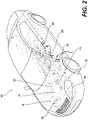
- Figure 2 illustrates the electric vehicle 100 of Figure 1 , with the optical fiber-based sensing membrane 102 removed, according to an example of the present disclosure.
- the battery pack 104 is shown with the sensing membrane 102 removed.
- the battery pack 104 may include, as shown, a plurality of battery cells 200.
- the sensing membrane 102 may be configured to sense thermal and/or strain variations, and/or vibrations associated with one, a few, or all of the battery cells 200 of the battery pack 104.
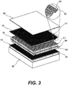
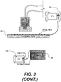
- Figure 3 illustrates a diagrammatic view illustrating the optical fiber-based sensing membrane 102 in use, according to an example of the present disclosure.
- the optical fiber-based sensing membrane 102 may include at least one optical fiber integrated in an adhesive substrate.
- a plurality of optical fibers 300 may be integrated in an adhesive substrate 302.
- sensing membranes may be disposed on upper and lower surfaces of the battery pack 104 in the orientation of Figure 3 .
- the battery pack 104 may include a plurality of battery cells.
- the battery cells may include, in the example shown, a cooling system 304 between upper and lower sets of battery cells in the orientation of Figure 3 .
- the upper and lower sensing membranes, and the battery pack 104 may be enclosed in an enclosure, with upper and lower layers 306 and 308 of the enclosure shown in the orientation of Figure 3 .
- the sensing membrane 102 at 310 may be used to sense thermal and/or strain variations, and/or vibrations of upper battery cells at 312, and the sensing membrane 102 at 314 may be used to sense thermal and/or strain variations, and/or vibrations of lower battery cells at 316.
- the adhesive substrate may include Polyimide, or another such material.
- the Polyimide material may provide the requisite durability with respect to vibrations associated with the battery pack 104 and/or other components that may be engaged with the sensing membrane 102.
- the Polyimide material may provide the requisite durability with respect to temperature variations associated with the battery pack 104 and/or other components, which may be on the order of -40 °C to 140 °C, or include a greater range than -40 °C to 140 °C.
- the Polyimide material may provide the requisite flexibility associated with surface variations associated with the battery pack 104 and/or other components that may be engaged with the sensing membrane 102.
- the Polyimide material may also be transparent, and thus provide sufficient transmission of light into the optical fiber for detection of light or an anomaly (e.g., a high temperature event) associated with the battery pack 104.
- the sensing membrane 102 may be of a light weight (e.g., 200 - 500g/m 2 ). In this regard, the sensing membrane 102 may add minimal weight with respect to the device being monitored for thermal and/or strain variations, and/or vibrations.
- the sensing membrane 102 may be approximately 0.5 mm, to thus minimize integration challenges with respect to the device being monitored for thermal and/or strain variations, and/or vibrations.
- the optical fibers embedded in the sensing membrane 102 may be on the order of 0.25 mm in thickness.
- such optical fibers may be treated after the sensing membrane is assembled, for example, by a combined action of pressure and temperature above the melting point of the optical fiber coating while the sensing membrane material is unaffected.
- the overall thickness of 0.5 mm may thus add minimal thickness associated with the battery pack 104.
- DTS distributed temperature sensing interrogator
- fiber sensing membrane 320 may be utilized to sense temperature, but also strain variations using a distributed strain sensing interrogator in place of the DTS.
- the distributed temperature sensing interrogator 318 which may include an OTDR, may be utilized with the various examples of the sensing membrane 102 as disclosed herein.
- Figure 4 illustrates a diagrammatic view illustrating an embedded distributed temperature sensor (eDTS) that utilizes the sensing membrane 102, according to an example of the present disclosure.
- eDTS embedded distributed temperature sensor
- an embedded distributed temperature sensor 400 may be positioned as shown for temperature sensing associated with an optical fiber 402.
- the optical fiber 402 may include arbitrary paths as shown at 404, and common paths as shown at 406.
- the minimal configuration may include one common path joining the two optical fiber ends, but higher accuracy may be obtained in the loss compensation with multiple common paths evenly distributed over the total sensing length, and an even higher accuracy may be obtained with a complete folding of the entire optical fiber.
- the embedded distributed temperature sensor 400 may provide for continuous monitoring of a device, such as the battery pack 104.
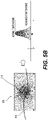
- Figures 5A and 5B respectively illustrate a temperature spatial resolution graph, and an example of spatial resolution, according to an example of the present disclosure.
- spatial resolution may represent a smallest length of the temperature affected fiber optic sensor for which a distributed fiber optic system can measure a reference temperature of a hotspot fiber condition within a specified temperature measurement error of the distributed temperature sensor system.
- a spatial resolution on the order of millimeters and including a delta of 0.1°C may be utilized for monitoring cells
- a spatial resolution on the order of centimeters and including a delta of 0.1°C may be utilized for monitoring modules
- a spatial resolution on the order of meters and including a delta of 1°C may be utilized for monitoring systems.
- an example of a 1.5 m temperature spatial resolution for a sensing fiber 500 is shown at 502.
- Examples of spatial resolution are illustrated for different fiber coil length, for example, of 1.0 m and 504, 1.5 m at 506, and 6.0 m at 508. As shown at 504, since the temperature spatial resolution is specified as 1.5 m, the measurement at 504 shows a lower than 90% temperature measurement. The measurement at 506 shows a greater than 90% temperature measurement, and the measurement at 508 shows a 100% temperature measurement.
- an optical fiber may not measure an amplitude accurately.
- an associated distributed temperature sensor may not measure an amplitude accurately.
- a spatial resolution of approximately 1.0 m may be specified to ascertain a complete measurement of the temperature spike.
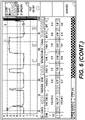
- Figure 6 illustrates further details of spatial resolution, according to an example of the present disclosure.
- spatial resolution may represent a shortest length of an optical fiber which has to be subjected to a localized temperature step in order that a system (e.g., a distributed temperature sensor) returns approximately 90% of the response (e.g., as shown at 600).
- the 90% response criteria may be applied to determine spatial resolution to thus consider a length required to monitor 80% of a step change.
- the temperature event may be detected but not accurately measured.
- it is technically challenging to accurately detect and measure temperature particularly for applications that include a relatively small spatial resolution, for example, on the order of millimeters or centimeters.
- Figure 7 illustrates the sensing membrane layout 122 including a coil with multiple layers, according to an example of the present disclosure.
- the sensing membrane layout 122 may include a total length of an optical fiber that is increased to a value that is higher than a spatial resolution of the associated fiber sensing solution.
- the sensing membrane layout 122 may include an optical fiber that is patterned in a coil as shown at 700 with single or multiple layers. The coils may be built according to different spooling techniques.
- the sensing membrane layout 122 may include an optical fiber or fibers with other geometric patterns.
- the coiling as shown at 700 may provide for accurate temperature measurement, as shown at 702.
- a number of the coils may be based on a total length that is needed for a specified spatial resolution as disclosed herein. For example, n coils that include a total length of x m may be utilized to provide a 90% or higher response. Thus a number of the coils may be determined based on a total length needed for a specified response, and a diameter of each coil. In this regard, each coil of a set of coils may include equal or unequal diameters.
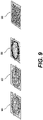
- Figures 8 and 9 illustrate further examples of the sensing membrane layout 122, according to an example of the present disclosure.
- the sensing membrane layout 122 may include an optical fiber or fibers with other geometric patterns.
- geometric patterns may include loops as shown at 800, a meander-line coil as shown at 802, and spirals as shown at 804 and 806.
- the loops as shown at 800 may represent a quasi-distributed two dimensional shape.
- the meander-line coil as shown at 802 may represent a distributed shape.
- Other types of shapes may include repetitive shapes with multiple loops, stacks of fiber loops, geometric patterns that include fiber crossing, square spirals, two dimensional spiral, three-dimensional spiral, etc.
- various temperature or strain events may be detected, for example, at 808, 810, and 812.
- various temperature or strain events may be detected across a single length of an optical fiber (e.g., at 808) or across multiple lengths of the optical fiber (e.g., at 810 and 812).
- the sensing membrane layout 122 may include other types of geometric patterns that include an optical fiber without crossing as shown at 900, an optical fiber with crossing as shown at 902, fiber strands with optical fiber crossing as shown at 904, and a replicated layout as shown at 906.
- Figure 10 illustrates the sensing membrane layout 122 including sliding loops, according to an example of the present disclosure.
- the sensing membrane 102 may include a sliding loops arrangement as shown at 1000.
- An additional transverse triangle sliding movement with an amplitude of the order of several mm and a slope exceeding one optical fiber diameter for each loop may be applied to avoid accumulation of several optical fiber layers as apparent at top and bottom at 1000.
- Another solution to fiber accumulation may include a hybrid concentric spiral and sliding layout, with, for example, N concentric turns applied and a N times larger sliding step (compared to one chosen for the pure sliding loop pattern, and therefore with an equivalent spatial resolution).
- the repeated pattern may cover the entire surface to be monitored with a single layer, but as shown at 1002, the sensing membrane 102 may include multiple layers with an horizontal offset in the orientation of Figure 10 , which may further increase the density of the optical fiber and associated spatial resolution of the sensor.
- Figure 11 illustrates the sensing membrane layout 122 including the sensing membrane 102 embedded in a battery cell insert, according to an example of the present disclosure.
- the sensing membrane 102 of the various geometric patterns disclosed herein may be embedded in a battery cell insert of the battery pack 104.
- a battery cell insert 1102 may be positioned on an upper surface of the battery cells in the orientation of Figure 11
- a battery cell insert 1104 may be positioned on the lower surface of the battery cells.
- the battery pack 104 may further include a collector plate 1106 positioned on an upper surface of the battery cell insert 1102, and a collector plate 1108 positioned on a lower surface of the battery cell insert 1104.
- the sensing membrane 102 may be embedded in battery cell inserts 1102 and 1104.
- Figure 12 illustrates the sensing membrane layout 122 including loops in series, according to an example of the present disclosure.
- the sensing membrane layout 122 may include loops in series as shown at 1200.
- each loop may be used to address a single battery cell 1202 of the battery pack 104.
- an associated loop may be used to detect a temperature, strain, and/or vibration event.
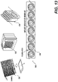
- Figure 13 illustrates further examples of the sensing membrane layout 122, according to an example of the present disclosure.
- the sensing membrane layout 122 may be applied to a variety of cell types.
- the sensing membrane layout 122 may include a meander-line coil layout applied to a single pouch cell.
- the sensing membrane layout 122 may include a ribbon-layout applied to a stack of cells as shown at 1304.
- this layout is shown in an unfolded configuration at 1306 and includes the sensing membrane 102 including fold areas 1308.
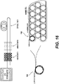
- Figure 14 illustrates the sensing membrane layout 122 including an optical fiber embedded in battery molded parts, according to an example of the present disclosure.
- the sensing membrane layout 122 may include an optical fiber embedded in a device, such as molded parts of the battery pack 104.
- an optical fiber may be inserted in an insert or thermally conductive gap filler of the battery pack 104.
- An example of an optical fiber inserted in an insert or thermally conductive gap filler of the battery pack 104 is shown at 1400.
- Other components associated with the battery pack 104 where an optical fiber or sensing membrane 102 may be inserted may include a battery pack sealing assembly at 1402, a thermal conductive adhesive at 1404, a structural adhesive at 1406, and/or a thermally conductive gap filler at 1408.
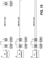
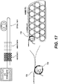
- FIGS 15-17 illustrate dynamic temperature sensing measurements and associated calibrations, according to an example of the present disclosure.
- the sensing membrane layout 122 as disclosed herein may include various loops and other geometric patterns.
- different calibration techniques may need to be applied with respect to loss distribution.
- distributed temperature sensing measurements may incur errors due to differential attenuation.
- the same temperature may be interpreted as different temperatures depending on a position along an optical fiber.
- calibration may be performed, for example, by utilizing reference zones, subjected to the same temperature, or subjected to a known absolute temperature. Different calibration methods may vary with measurement setup (e.g., single-ended, dual source, etc.).
- a plurality (e.g., two) reference loops may be superimposed, and are therefore subjected to the same temperature.
- an absolute value (offset) may be calibrated during initiation of the temperature, strain, and/or vibration sensing.
- a plurality (e.g., two) reference loops may be superimposed, and are therefore subjected to the same temperature.
- the calibration may be based on the reading of a dedicated sensor (e.g., a thermocouple as shown at 1702).
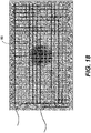
- Figure 18 illustrates a fiber grid overlay, according to an example of the present disclosure.
- the sensing membrane layout 122 including multiple optical fiber crossings may be utilized to either detect pressure, strain, vibration, and/or mechanical shock using distributed loss or strain.
- the multiple optical fiber crossings may increase a detection capability with respect to pressure, strain, vibration, and/or mechanical shock.
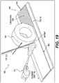
- Figure 19 illustrates a method of manufacturing the sensing membrane 102, according to an example of the present disclosure.
- the sensing membrane 102 that includes various examples of the sensing membrane layout 122 as disclosed herein may be manufactured as shown.
- the sensing membrane 102 may include a substrate 1900 that includes at least one optical fiber 1902 provided in a geometric pattern as shown at 1904.
- the optical fiber 1902 may be fed at 1906.
- a consolidation roller 1908 may uniformly place the optical fiber 1902 onto the substrate 1900.
- a heating source 1910 may heat the substrate to a specified temperature to allow for embedding of the optical fiber 1902 into the substrate 1900. In this manner, various geometric patterns as disclosed herein may be formed with respect to the sensing membrane layout 122.
Landscapes
- Physics & Mathematics (AREA)
- General Physics & Mathematics (AREA)
- Engineering & Computer Science (AREA)
- Chemical & Material Sciences (AREA)
- Manufacturing & Machinery (AREA)
- General Chemical & Material Sciences (AREA)
- Electrochemistry (AREA)
- Chemical Kinetics & Catalysis (AREA)
- Life Sciences & Earth Sciences (AREA)
- Transportation (AREA)
- Mechanical Engineering (AREA)
- Power Engineering (AREA)
- Sustainable Energy (AREA)
- Sustainable Development (AREA)
- Optics & Photonics (AREA)
- Microelectronics & Electronic Packaging (AREA)
- Analytical Chemistry (AREA)
- Length Measuring Devices By Optical Means (AREA)
- Light Guides In General And Applications Therefor (AREA)
- Measuring Temperature Or Quantity Of Heat (AREA)
Applications Claiming Priority (2)
| Application Number | Priority Date | Filing Date | Title |
|---|---|---|---|
| EP21305506 | 2021-04-16 | ||
| EP21305505 | 2021-04-16 |
Publications (4)
| Publication Number | Publication Date |
|---|---|
| EP4074536A2 true EP4074536A2 (de) | 2022-10-19 |
| EP4074536A3 EP4074536A3 (de) | 2022-12-21 |
| EP4074536B1 EP4074536B1 (de) | 2025-06-11 |
| EP4074536C0 EP4074536C0 (de) | 2025-06-11 |
Family
ID=81074176
Family Applications (3)
| Application Number | Title | Priority Date | Filing Date |
|---|---|---|---|
| EP22167553.1A Active EP4074536B1 (de) | 2021-04-16 | 2022-04-11 | Glasfaserbasiertes sensormembran-layout |
| EP25172952.1A Pending EP4571934A3 (de) | 2021-04-16 | 2022-04-11 | Auf optischer faser basierende messmembran |
| EP22167563.0A Active EP4074537B1 (de) | 2021-04-16 | 2022-04-11 | Glasfaserbasierte sensormembran |
Family Applications After (2)
| Application Number | Title | Priority Date | Filing Date |
|---|---|---|---|
| EP25172952.1A Pending EP4571934A3 (de) | 2021-04-16 | 2022-04-11 | Auf optischer faser basierende messmembran |
| EP22167563.0A Active EP4074537B1 (de) | 2021-04-16 | 2022-04-11 | Glasfaserbasierte sensormembran |
Country Status (3)
| Country | Link |
|---|---|
| US (4) | US12031859B2 (de) |
| EP (3) | EP4074536B1 (de) |
| CN (2) | CN115218934B (de) |
Families Citing this family (7)
| Publication number | Priority date | Publication date | Assignee | Title |
|---|---|---|---|---|
| EP4074536B1 (de) | 2021-04-16 | 2025-06-11 | Viavi Solutions Inc. | Glasfaserbasiertes sensormembran-layout |
| US12436003B2 (en) * | 2022-05-13 | 2025-10-07 | Nec Corporation | System to measure coil locations and lengths on aerial fiber cables by distributed fiber sensing for decision making |
| CN115638909B (zh) * | 2022-11-04 | 2025-06-17 | 之江实验室 | 一种基于聚合物光纤结敏感结构与硅胶基底的硬度传感器 |
| EP4414667A1 (de) * | 2023-02-07 | 2024-08-14 | Viavi Solutions Inc. | Glasfaserbasiertes messmembranlayout |
| US20240263994A1 (en) * | 2023-02-07 | 2024-08-08 | Viavi Solutions Inc. | Optical fiber-based sensing membrane layout |
| CN219892234U (zh) * | 2023-07-10 | 2023-10-24 | 宁德时代新能源科技股份有限公司 | 一种电池、电动车辆和用电装置 |
| CN120874464B (zh) * | 2025-09-22 | 2025-12-09 | 山东大学 | 一种光纤传感器植入评估、无损植入方法及系统 |
Family Cites Families (39)
| Publication number | Priority date | Publication date | Assignee | Title |
|---|---|---|---|---|
| US20040118997A1 (en) * | 2001-12-12 | 2004-06-24 | Lehmann Kevin K. | Tapered fiber optic strain gauge using cavity ring-down spectroscopy |
| KR100488524B1 (ko) | 2003-04-09 | 2005-05-11 | 삼성전자주식회사 | 로봇충전장치 |
| US7608812B2 (en) * | 2004-11-05 | 2009-10-27 | Tamperproof Container Licensing Corp. | Tamper detection system |
| DE102008057710A1 (de) * | 2008-11-17 | 2010-05-27 | Li-Tec Battery Gmbh | Nach galvanischen Prinzipien arbeitende elektrische Einrichtung, wie ein Lithium-Ionen-Akkumulator, mit einem Temperatursensor |
| CN101750057A (zh) * | 2008-12-09 | 2010-06-23 | 姜恩颖 | 一种新型光纤陀螺 |
| GB0919899D0 (en) * | 2009-11-13 | 2009-12-30 | Qinetiq Ltd | Fibre optic distributed sensing |
| US20110267598A1 (en) * | 2010-04-30 | 2011-11-03 | Vestas Wind Systems A/S | Optical sensor system and detecting method for an enclosed semiconductor device module |
| US20130034324A1 (en) * | 2011-08-03 | 2013-02-07 | Baker Hughes Incorporated | Optical fiber sensor and method for adhering an optical fiber to a substrate |
| EP2672234B1 (de) * | 2012-06-05 | 2014-12-03 | Airbus Operations GmbH | System und Verfahren zur Überwachung einer Komponente in der Produktion sowie im Betrieb |
| US9209494B2 (en) * | 2012-09-28 | 2015-12-08 | Palo Alto Research Center Incorporated | Monitoring/managing electrochemical energy device using detected intercalation stage changes |
| CN103376066B (zh) * | 2013-06-21 | 2016-04-20 | 浙江大学宁波理工学院 | 用于监测木结构应变的分布式传感光纤的安装方法 |
| US9990866B2 (en) * | 2013-07-31 | 2018-06-05 | Opticallock, Inc. | Container tamper-proof protection by use of printed fiber optics manufacturing and integrated sensors |
| WO2015147977A1 (en) * | 2014-03-24 | 2015-10-01 | General Electric Company | Battery cell health monitoring using eddy currents |
| US9583796B2 (en) | 2014-04-01 | 2017-02-28 | Palo Alto Research Center Incorporated | Method for monitoring/managing electrochemical energy device by detecting intercalation stage changes |
| US9677916B2 (en) | 2014-07-15 | 2017-06-13 | Palo Alto Research Center Incorporated | Energy system monitoring |
| US10446886B2 (en) * | 2014-07-23 | 2019-10-15 | Palo Alto Research Center Incorporated | Embedded fiber optic cables for battery management |
| US10861682B2 (en) * | 2014-07-31 | 2020-12-08 | iSenseCloud, Inc. | Test wafer with optical fiber with Bragg Grating sensors |
| GB2529674B (en) * | 2014-08-28 | 2019-07-10 | Silixa Ltd | Flexible Substrate Fiber Optic Sensing Mat For Distributed Acoustic Sensing |
| GB201417836D0 (en) * | 2014-10-08 | 2014-11-19 | Optasense Holdings Ltd | Fibre optic cable with transverse sensitivity |
| EP3104447B1 (de) * | 2015-06-09 | 2019-04-24 | Volvo Car Corporation | Schadenserkennung und warnsystem eines batteriepacks |
| US10854932B2 (en) | 2015-07-28 | 2020-12-01 | Palo Alto Research Center Incorporated | Method and system to separate optically measured coupled parameters |
| WO2017040525A1 (en) * | 2015-08-30 | 2017-03-09 | Opticallock, Inc. | Container tamper-proof protection by use of printed fiber optics manufacturing and integrated sensors |
| US11420532B2 (en) | 2015-11-11 | 2022-08-23 | Rivian Ip Holdings, Llc | Systems and methods for monitoring and enhancing utilization of batteries for electric vehicles based on vehicle usage |
| US9933570B2 (en) * | 2016-03-01 | 2018-04-03 | Futurewei Technologies, Inc. | Integration of V-grooves on silicon-on-insulator (SOI) platform for direct fiber coupling |
| US10589629B2 (en) | 2016-09-14 | 2020-03-17 | GM Global Technology Operations LLC | Electrochemical device sensor and method of making and using the same |
| US20180321325A1 (en) * | 2017-05-08 | 2018-11-08 | Aleksandra Fortier | Embedded Sensors for In-Situ Cell Monitoring of Batteries |
| CA3065320C (en) * | 2017-06-16 | 2023-09-05 | Saint-Gobain Adfors Canada, Ltd. | Sensing textile |
| US10857889B2 (en) | 2017-10-04 | 2020-12-08 | Nio Usa, Inc. | Highly-integrated fail operational e-powertrain for autonomous driving application |
| EP3525279A1 (de) * | 2018-02-09 | 2019-08-14 | Nederlandse Organisatie voor toegepast- natuurwetenschappelijk onderzoek TNO | Thermistore auf flexibler schichten und derer verwendung zur temperaturmessung im batteriepack |
| CN108749607A (zh) | 2018-05-23 | 2018-11-06 | 清华大学深圳研究生院 | 一种基于云计算的电动汽车动力电池管理和监控系统 |
| US11662228B2 (en) * | 2018-06-22 | 2023-05-30 | The University Of Hong Kong | Real-time surface shape sensing for flexible structures |
| CN109457902A (zh) | 2018-11-06 | 2019-03-12 | 天津市龙建科技咨询有限公司 | 新型建筑节能地板 |
| DE102020105308A1 (de) * | 2019-05-02 | 2020-11-05 | CrossLink GmbH | Temperiersystem für Lithium-Ionen-Batteriezellen |
| CN110285768A (zh) * | 2019-06-25 | 2019-09-27 | 国家电网公司华中分部 | 一种基于光纤光栅传感器的输电线路杆塔角钢应变在线监测装置及方法 |
| US10807493B1 (en) | 2019-07-30 | 2020-10-20 | Goodwyn George Reeves | Vehicle battery pack and battery exchange system |
| CN111102934B (zh) * | 2019-12-25 | 2021-03-26 | 傲普(上海)新能源有限公司 | 一种监测电芯膨胀及形变的方法 |
| CN112103576B (zh) * | 2020-09-21 | 2021-06-22 | 北京理工大学 | 一种智能电池 |
| US20220332217A1 (en) | 2021-04-16 | 2022-10-20 | Viavi Solutions Inc. | Data collection and analysis-based device monitoring |
| EP4074536B1 (de) | 2021-04-16 | 2025-06-11 | Viavi Solutions Inc. | Glasfaserbasiertes sensormembran-layout |
-
2022
- 2022-04-11 EP EP22167553.1A patent/EP4074536B1/de active Active
- 2022-04-11 CN CN202210375230.0A patent/CN115218934B/zh active Active
- 2022-04-11 EP EP25172952.1A patent/EP4571934A3/de active Pending
- 2022-04-11 EP EP22167563.0A patent/EP4074537B1/de active Active
- 2022-04-11 CN CN202210374987.8A patent/CN115218933B/zh active Active
- 2022-04-12 US US17/718,416 patent/US12031859B2/en active Active
- 2022-04-12 US US17/718,377 patent/US12092515B2/en active Active
-
2024
- 2024-05-22 US US18/671,411 patent/US12474202B2/en active Active
- 2024-05-22 US US18/671,384 patent/US12281934B2/en active Active
Also Published As
| Publication number | Publication date |
|---|---|
| US12092515B2 (en) | 2024-09-17 |
| EP4074536A3 (de) | 2022-12-21 |
| US12474202B2 (en) | 2025-11-18 |
| EP4074537C0 (de) | 2025-10-29 |
| EP4074537A1 (de) | 2022-10-19 |
| EP4571934A3 (de) | 2025-09-10 |
| CN115218934B (zh) | 2025-11-11 |
| US20240310207A1 (en) | 2024-09-19 |
| EP4074537B1 (de) | 2025-10-29 |
| EP4571934A2 (de) | 2025-06-18 |
| US20220333962A1 (en) | 2022-10-20 |
| CN115218933A (zh) | 2022-10-21 |
| US20220333976A1 (en) | 2022-10-20 |
| US20240310208A1 (en) | 2024-09-19 |
| CN115218933B (zh) | 2025-10-17 |
| US12281934B2 (en) | 2025-04-22 |
| EP4074536B1 (de) | 2025-06-11 |
| US12031859B2 (en) | 2024-07-09 |
| EP4074536C0 (de) | 2025-06-11 |
| CN115218934A (zh) | 2022-10-21 |
Similar Documents
| Publication | Publication Date | Title |
|---|---|---|
| EP4074536B1 (de) | Glasfaserbasiertes sensormembran-layout | |
| Yu et al. | Distributed internal thermal monitoring of lithium ion batteries with fibre sensors | |
| CN112067155B (zh) | 基于ofdr锂电池温度动态监测方法 | |
| Chen et al. | Temperature monitoring for 500 kV oil-filled submarine cable based on BOTDA distributed optical fiber sensing technology: Method and application | |
| CN104864911B (zh) | 基于光纤法珀腔与光纤光栅双参量联合测量的高速解调装置及方法 | |
| Knobloch et al. | Fabrication of multimeasurand sensor for monitoring of a Li-ion battery | |
| CN103674083B (zh) | 高速粒子撞击测试系统 | |
| Meyer et al. | Fiber optical sensors for enhanced battery safety | |
| CN111811682B (zh) | 一种超导磁悬浮装置温度检测系统及方法 | |
| CN115790891B (zh) | 含光纤传感胶带的锂电池安全监测系统及监测方法 | |
| CN118011208A (zh) | 一种锂离子电池单体内部状态监测系统 | |
| Matuck et al. | Customized optical fiber birefringent sensors to multipoint and simultaneous temperature and radial strain tracking of lithium‐ion batteries | |
| Atchison et al. | Thermal monitoring of series and parallel connected lithium-ion battery modules using fiber optic sensors | |
| Atchison et al. | Fiber optic based thermal and strain sensing of lithium-ion batteries at the individual cell level | |
| CN115014572A (zh) | 一种利用光纤瑞利散射提升温度传感阵列性能的方法 | |
| Kim et al. | A remote FBG-OFDR thermometry sensor for EV energy systems | |
| EP4414667A1 (de) | Glasfaserbasiertes messmembranlayout | |
| US20240263994A1 (en) | Optical fiber-based sensing membrane layout | |
| CN220510090U (zh) | 储能设备 | |
| CN113972413B (zh) | 可实时监测电解质温度的固态电池及温度监测方法 | |
| CN114166370A (zh) | 一种动力电池内部核心温度的检测方法 | |
| CN219416477U (zh) | 层压机测温装置 | |
| CN114261853B (zh) | 一种分布式光纤传感设备3d打印光纤盘绕装置及方法 | |
| Plus | Thermal Monitoring of Series and Parallel Connected Lithium-ion Battery Modules Using Fiber Optic Sensors | |
| KR20250116331A (ko) | 화재 경보 장치 및 이의 제조 방법 |
Legal Events
| Date | Code | Title | Description |
|---|---|---|---|
| PUAI | Public reference made under article 153(3) epc to a published international application that has entered the european phase |
Free format text: ORIGINAL CODE: 0009012 |
|
| STAA | Information on the status of an ep patent application or granted ep patent |
Free format text: STATUS: THE APPLICATION HAS BEEN PUBLISHED |
|
| AK | Designated contracting states |
Kind code of ref document: A2 Designated state(s): AL AT BE BG CH CY CZ DE DK EE ES FI FR GB GR HR HU IE IS IT LI LT LU LV MC MK MT NL NO PL PT RO RS SE SI SK SM TR |
|
| PUAL | Search report despatched |
Free format text: ORIGINAL CODE: 0009013 |
|
| AK | Designated contracting states |
Kind code of ref document: A3 Designated state(s): AL AT BE BG CH CY CZ DE DK EE ES FI FR GB GR HR HU IE IS IT LI LT LU LV MC MK MT NL NO PL PT RO RS SE SI SK SM TR |
|
| RIC1 | Information provided on ipc code assigned before grant |
Ipc: G02B 6/36 20060101ALI20221115BHEP Ipc: H01M 10/48 20060101ALI20221115BHEP Ipc: H01M 10/42 20060101ALI20221115BHEP Ipc: G01M 11/08 20060101ALI20221115BHEP Ipc: G01L 1/24 20060101ALI20221115BHEP Ipc: G01K 11/32 20210101ALI20221115BHEP Ipc: G01D 5/353 20060101ALI20221115BHEP Ipc: B60L 3/00 20190101ALI20221115BHEP Ipc: B60L 15/00 20060101AFI20221115BHEP |
|
| STAA | Information on the status of an ep patent application or granted ep patent |
Free format text: STATUS: REQUEST FOR EXAMINATION WAS MADE |
|
| P01 | Opt-out of the competence of the unified patent court (upc) registered |
Effective date: 20230530 |
|
| 17P | Request for examination filed |
Effective date: 20230621 |
|
| RBV | Designated contracting states (corrected) |
Designated state(s): AL AT BE BG CH CY CZ DE DK EE ES FI FR GB GR HR HU IE IS IT LI LT LU LV MC MK MT NL NO PL PT RO RS SE SI SK SM TR |
|
| STAA | Information on the status of an ep patent application or granted ep patent |
Free format text: STATUS: EXAMINATION IS IN PROGRESS |
|
| 17Q | First examination report despatched |
Effective date: 20231019 |
|
| REG | Reference to a national code |
Ref country code: DE Free format text: PREVIOUS MAIN CLASS: B60L0015000000 Ref country code: DE Ref legal event code: R079 Ref document number: 602022015712 Country of ref document: DE Free format text: PREVIOUS MAIN CLASS: B60L0015000000 Ipc: B60L0050640000 |
|
| GRAP | Despatch of communication of intention to grant a patent |
Free format text: ORIGINAL CODE: EPIDOSNIGR1 |
|
| STAA | Information on the status of an ep patent application or granted ep patent |
Free format text: STATUS: GRANT OF PATENT IS INTENDED |
|
| RIC1 | Information provided on ipc code assigned before grant |
Ipc: H01M 10/48 20060101ALI20250102BHEP Ipc: G01M 11/08 20060101ALI20250102BHEP Ipc: G01L 1/24 20060101ALI20250102BHEP Ipc: G01K 11/32 20210101ALI20250102BHEP Ipc: G01D 5/353 20060101ALI20250102BHEP Ipc: G01K 1/14 20210101ALI20250102BHEP Ipc: B60L 50/60 20190101ALI20250102BHEP Ipc: B60L 50/64 20190101AFI20250102BHEP |
|
| INTG | Intention to grant announced |
Effective date: 20250117 |
|
| GRAS | Grant fee paid |
Free format text: ORIGINAL CODE: EPIDOSNIGR3 |
|
| GRAA | (expected) grant |
Free format text: ORIGINAL CODE: 0009210 |
|
| STAA | Information on the status of an ep patent application or granted ep patent |
Free format text: STATUS: THE PATENT HAS BEEN GRANTED |
|
| AK | Designated contracting states |
Kind code of ref document: B1 Designated state(s): AL AT BE BG CH CY CZ DE DK EE ES FI FR GB GR HR HU IE IS IT LI LT LU LV MC MK MT NL NO PL PT RO RS SE SI SK SM TR |
|
| REG | Reference to a national code |
Ref country code: GB Ref legal event code: FG4D |
|
| REG | Reference to a national code |
Ref country code: CH Ref legal event code: EP |
|
| REG | Reference to a national code |
Ref country code: DE Ref legal event code: R096 Ref document number: 602022015712 Country of ref document: DE |
|
| REG | Reference to a national code |
Ref country code: IE Ref legal event code: FG4D |
|
| U01 | Request for unitary effect filed |
Effective date: 20250702 |
|
| U07 | Unitary effect registered |
Designated state(s): AT BE BG DE DK EE FI FR IT LT LU LV MT NL PT RO SE SI Effective date: 20250708 |
|
| PG25 | Lapsed in a contracting state [announced via postgrant information from national office to epo] |
Ref country code: ES Free format text: LAPSE BECAUSE OF FAILURE TO SUBMIT A TRANSLATION OF THE DESCRIPTION OR TO PAY THE FEE WITHIN THE PRESCRIBED TIME-LIMIT Effective date: 20250611 |
|
| PG25 | Lapsed in a contracting state [announced via postgrant information from national office to epo] |
Ref country code: GR Free format text: LAPSE BECAUSE OF FAILURE TO SUBMIT A TRANSLATION OF THE DESCRIPTION OR TO PAY THE FEE WITHIN THE PRESCRIBED TIME-LIMIT Effective date: 20250912 Ref country code: NO Free format text: LAPSE BECAUSE OF FAILURE TO SUBMIT A TRANSLATION OF THE DESCRIPTION OR TO PAY THE FEE WITHIN THE PRESCRIBED TIME-LIMIT Effective date: 20250911 |
|
| PG25 | Lapsed in a contracting state [announced via postgrant information from national office to epo] |
Ref country code: HR Free format text: LAPSE BECAUSE OF FAILURE TO SUBMIT A TRANSLATION OF THE DESCRIPTION OR TO PAY THE FEE WITHIN THE PRESCRIBED TIME-LIMIT Effective date: 20250611 |
|
| PG25 | Lapsed in a contracting state [announced via postgrant information from national office to epo] |
Ref country code: RS Free format text: LAPSE BECAUSE OF FAILURE TO SUBMIT A TRANSLATION OF THE DESCRIPTION OR TO PAY THE FEE WITHIN THE PRESCRIBED TIME-LIMIT Effective date: 20250911 |
|
| PG25 | Lapsed in a contracting state [announced via postgrant information from national office to epo] |
Ref country code: IS Free format text: LAPSE BECAUSE OF FAILURE TO SUBMIT A TRANSLATION OF THE DESCRIPTION OR TO PAY THE FEE WITHIN THE PRESCRIBED TIME-LIMIT Effective date: 20251011 |
|
| PG25 | Lapsed in a contracting state [announced via postgrant information from national office to epo] |
Ref country code: SM Free format text: LAPSE BECAUSE OF FAILURE TO SUBMIT A TRANSLATION OF THE DESCRIPTION OR TO PAY THE FEE WITHIN THE PRESCRIBED TIME-LIMIT Effective date: 20250611 |