EP4074530A1 - Device for screening a window of a vehicle - Google Patents
Device for screening a window of a vehicle Download PDFInfo
- Publication number
- EP4074530A1 EP4074530A1 EP22165808.1A EP22165808A EP4074530A1 EP 4074530 A1 EP4074530 A1 EP 4074530A1 EP 22165808 A EP22165808 A EP 22165808A EP 4074530 A1 EP4074530 A1 EP 4074530A1
- Authority
- EP
- European Patent Office
- Prior art keywords
- screen
- upright
- rail
- operating configuration
- window
- Prior art date
- Legal status (The legal status is an assumption and is not a legal conclusion. Google has not performed a legal analysis and makes no representation as to the accuracy of the status listed.)
- Granted
Links
- 238000012216 screening Methods 0.000 title claims abstract description 17
- 239000000463 material Substances 0.000 description 3
- 239000004744 fabric Substances 0.000 description 2
- 230000000694 effects Effects 0.000 description 1
- 238000009413 insulation Methods 0.000 description 1
- 230000010355 oscillation Effects 0.000 description 1
- 238000012856 packing Methods 0.000 description 1
- 239000004753 textile Substances 0.000 description 1
Images

Classifications
-
- B—PERFORMING OPERATIONS; TRANSPORTING
- B60—VEHICLES IN GENERAL
- B60J—WINDOWS, WINDSCREENS, NON-FIXED ROOFS, DOORS, OR SIMILAR DEVICES FOR VEHICLES; REMOVABLE EXTERNAL PROTECTIVE COVERINGS SPECIALLY ADAPTED FOR VEHICLES
- B60J1/00—Windows; Windscreens; Accessories therefor
- B60J1/20—Accessories, e.g. wind deflectors, blinds
- B60J1/2011—Blinds; curtains or screens reducing heat or light intensity
- B60J1/2013—Roller blinds
- B60J1/2036—Roller blinds characterised by structural elements
- B60J1/2041—Blind sheets, e.g. shape of sheets, reinforcements in sheets, materials therefor
-
- B—PERFORMING OPERATIONS; TRANSPORTING
- B60—VEHICLES IN GENERAL
- B60J—WINDOWS, WINDSCREENS, NON-FIXED ROOFS, DOORS, OR SIMILAR DEVICES FOR VEHICLES; REMOVABLE EXTERNAL PROTECTIVE COVERINGS SPECIALLY ADAPTED FOR VEHICLES
- B60J1/00—Windows; Windscreens; Accessories therefor
- B60J1/20—Accessories, e.g. wind deflectors, blinds
- B60J1/2011—Blinds; curtains or screens reducing heat or light intensity
- B60J1/2013—Roller blinds
- B60J1/2036—Roller blinds characterised by structural elements
- B60J1/2047—End position holding means, e.g. suction cups, hooks on a vehicle, indentations on guides
-
- B—PERFORMING OPERATIONS; TRANSPORTING
- B60—VEHICLES IN GENERAL
- B60J—WINDOWS, WINDSCREENS, NON-FIXED ROOFS, DOORS, OR SIMILAR DEVICES FOR VEHICLES; REMOVABLE EXTERNAL PROTECTIVE COVERINGS SPECIALLY ADAPTED FOR VEHICLES
- B60J1/00—Windows; Windscreens; Accessories therefor
- B60J1/20—Accessories, e.g. wind deflectors, blinds
- B60J1/2011—Blinds; curtains or screens reducing heat or light intensity
- B60J1/2013—Roller blinds
- B60J1/2063—Mounting arrangements for roller blind or its storage box, e.g. integration into beltline or window frame
-
- B—PERFORMING OPERATIONS; TRANSPORTING
- B60—VEHICLES IN GENERAL
- B60J—WINDOWS, WINDSCREENS, NON-FIXED ROOFS, DOORS, OR SIMILAR DEVICES FOR VEHICLES; REMOVABLE EXTERNAL PROTECTIVE COVERINGS SPECIALLY ADAPTED FOR VEHICLES
- B60J1/00—Windows; Windscreens; Accessories therefor
- B60J1/20—Accessories, e.g. wind deflectors, blinds
- B60J1/2011—Blinds; curtains or screens reducing heat or light intensity
- B60J1/2091—Foldable sunscreens
Definitions
- This invention relates to a device for screening a window of a vehicle.
- these fabrics are usually stored inside the cabin, and when required they are positioned on the window and locked, using systems for attachment to the frame of the vehicle.
- the screen engages the window, thereby creating the screening of the window, whilst in the closed configuration the screen is positioned to the side of the window, freeing up the view.
- the aim of the invention is therefore to provide a device for screening a window of a vehicle which is able to overcome the above-mentioned drawbacks of the prior art.
- a further aim of the invention is to provide a device for screening a window which is at the same time practical to use and simple and inexpensive to make. According to the invention, these aims and others are achieved by a device for screening a window of a vehicle comprising the technical features described in the accompanying claims.
- the numeral 1 denotes in its entirety a device for screening a window F of a vehicle V made in accordance with the invention, hereinafter also referred to simply as the device 1.
- the device 1 comprises a frame 2, a first rail 3 and a screen 4.
- the frame 2 of the device 1 is stably engaged with the vehicle V.
- the frame 2 is engaged with the vehicle V by means of screw 20.
- the screws 20 define for the device 1 means for locking the frame 2 to the vehicle V.
- the frame 2 comprises a first upright 21, and a second upright 22.
- the term "upright” means a structural element with a substantially vertical extension relative to the ground.
- a first 23 and a second 24 transversal element are positioned transversally to the first 21 and to the second 22 upright, in such a way as to define a supporting structure to be stably fixed to the vehicle V, as illustrated in Figure 1 .
- the frame 2 is arranged on the window of a door or a hatchback of the vehicle V.
- one of either the first 21 or the second 22 upright has a containment compartment.
- the upright 22 has the containment compartment 221.
- the containment compartment 221 allows the screen 4 to be stored when it is not used.
- the containment compartment 221 is made between the frame 2 of the device 1 and the frame of the vehicle V.
- the first rail 3 is positioned between the first 21 and the second 22 upright.
- the first rail 3 is at least partly hidden from view by the second transversal element 24.
- the second transversal element 24 contributes to supporting the first rail 3, to prevent undesired oscillations of the first rail 3.
- the first rail 3 advantageously has an oval cross-section to prevent the screen 4 from tilting in a direction of rotation coinciding with the first rail 3.
- the screen 4 is of the retractable type, in such a way that it can be easily stored, occupying a relatively small space.
- the screen is made of materials chosen from among plastic, elastic, textile materials or a combination of these, such as to withstand a fatigue stress for a predetermined number of screen opening and closing cycles.
- the screen 4 is made of materials such as to occupy a limited volume, in such a way as to reduce the total dimensions of the device 1.
- the screen 4 comprises a front edge 41 which is free to slide on the first rail 3, and a rear edge 42 fixed to the second upright 22.
- the screen 4 also comprises an upper edge 43 extending between the front edge 41 and the second upright 22.
- the screen 4 also comprises a lower edge 44, opposite the upper edge 43, for engaging on the first rail 3.
- the screen 4 is of the cell-like type.
- the screen 4 comprises a plurality of closed cells 44 in such a way that each cell 44 defines a sort of tubular structure, as illustrated in Figure 2 .
- the screen 4 advantageously has a concertina shape, like a fan, for facilitating the packing of the screen 4 when it is closed.
- the device 1 also comprises a connecting rod 5 and a bracket 6.
- the connecting rod 5 is hinged with a relative first end 51 to the front edge 41 of the screen 4, and extends on the upper edge 43.
- the connecting rod 5 engages with the upper edge 43 of the screen 4 only partly.
- the connecting rod 5 defines part of the closing and locking surface SC screen 4 in the containment compartment 221.
- the closing surface SC is defined by the front edge 41 and the connecting rod 5 in the first non-operating configuration C, as described below and illustrated in Figure 3 .
- the length L of the connecting rod 5 is determined by the geometrical shape of the window F, as shown in Figure 1 .
- the height H of the first upright 21 defines the height H' of the front edge 41.
- the height H' is equal to the height H except for the tolerances necessary for the correct sliding of the screen 4 and an adequate engagement of the front edge 41 with the first upright 21.
- the difference between the height HH of the second upright 22 and the height H' of the front edge 41 defines the length L of the connecting rod 5, except for tolerances necessary for the correct sliding of the screen 4.
- the bracket 6 is hinged at a second end 52 of the connecting rod 5, as illustrated in Figure 2 .
- the bracket 6 is supported by the screen 4.
- the screen 4 comprises at least one seat 40 for housing the bracket 6, as illustrated in Figure 2 .
- the bracket 6 is inserted in one of the cells 44, for translating in the direction T by sliding within one of the cells 44, as described in more detail below.
- the device 1 comprises a second rail 7 configured to engage with part of the upper edge 43 of the screen 4. In that way, it is supported by the screen 4 which is thus more easily maintained in position, that is to say, preventing the screen 4 from tipping and facilitating its sliding.
- the second rail 7 is constrained by a relative first end 71 to the second upright 22, and by a relative second end 72 to the frame 2.
- the second end 72 is stably connected to the first transversal element 23 of the frame 2, engaging the first transversal member 23 only partly. This allows the constructional structure to be simplified and to easily adapt the device 1, and more specifically, the screen 4, to different shapes of the window F.
- the screen 4 is configured to translate on the first rail 3 for moving between a first non-operating configuration C, wherein the screen 4 is entirely positioned inside the containment compartment 221, and at least a second operating configuration A, wherein the front edge 41 is at the first upright 21 and the screen 4 is extended between the first 21 and the second 22 upright.
- Figure 3 shows the first non-operative configuration C.
- the screen 4 is placed inside the containment compartment 221.
- the front edge 41 and the connecting rod 5 are coplanar and aligned along the same direction so as to define the closing surface SC of the screen 4 inside the containment compartment 221.
- bracket 6 is aligned with the connecting rod 5, in such a way as to occupy as little space as possible.
- the device 1 moves to a second operating configuration A, shown in Figure 4 .
- the screen 4 translates along the first rail 3, and the second rail 7.
- the bracket 6 translates along a direction T transversal to the first rail 3 and belonging to the plane defined by the frame 2.
- the translation of the bracket 6 thus allows the rotation of the connecting rod 5 to be determined, in such a way that the connecting rod 5 can be adapted to different configurations of use.
- bracket 6 allows the screen 4 to be supported and to keep it in position to cover the window F in the second operating configuration A, without the screen 4 folding bask on itself.
- the connecting rod 5 also facilitates the driving of the screen 4, contributing to imparting a force on the front edge 41.
- the window F is completely covered by the screen 4, and thus screened.
- the device 1 returns to a first non-operating configuration C, illustrated in Figure 3 .
- the containment compartment 221 is made in the form of a box-shaped element stably connected to the frame 2.
- the box-shaped element is applied at one of either the first 21 or the second 22 upright.
- the screen 4 is of the heat insulating type, in such a way as to allow both the screening of the window F and the thermal insulation of the vehicle V.
- the device 1 comprises at least one magnet, not illustrated, positioned at least at one between the first upright 21 and the second upright 22 for firmly fixing the screen 4 in the second operating configuration A and in the first non-operating configuration C, respectively.
- Grips of different types such as, for example, handles, are positioned on the screen 4, so as to facilitate the translation along the rail 3.
- the device for screening a window of a vehicle according to the invention achieves the preset aims and brings important advantages.
- a first advantage of the screening device according to the invention is the possibility of making a device which can be easily adapted to different shapes of the window. Another advantage is the possibility of reducing the risk of breakages of the screen and/or the device after repeated use of the screen.
- a further advantage is due to the fact that the screen may be hidden from view.
- Yet another advantage is due to the possibility of keeping the screen in position, being able to omit, at least partly, the upper rail, or in any case reduce it. Yet another advantage is the possibility of reducing the constructional complexity of a screening device.
Landscapes
- Engineering & Computer Science (AREA)
- Mechanical Engineering (AREA)
- Window Of Vehicle (AREA)
- Vehicle Waterproofing, Decoration, And Sanitation Devices (AREA)
Abstract
Description
- This invention relates to a device for screening a window of a vehicle.
- In the sector of vehicles, such as, for example, camper vans and motor homes, the use of large windscreens and windows is preferred in order to illuminate as much as possible both the driver's cab and the habitable area of the vehicle.
- However, this situation has drawbacks, partly due precisely to the size of the windscreen and windows.
- In fact, in order to screen the cabin of the vehicle it is necessary to use screening fabrics or curtains which are applied to the outside or the inside the window.
- In both cases, these fabrics are usually stored inside the cabin, and when required they are positioned on the window and locked, using systems for attachment to the frame of the vehicle.
- These solutions have the drawback due to the fact that the screens, when not used, occupy the space, which is already limited, designed for storing objects in the cabin of the vehicle.
- Moreover, these screens, being detachable from the window, risk being forgotten or left in the most varied of places.
- For this reason, there are prior art solutions which involve the use of screening devices fixed stably to the window, and which have at least two configurations, one open and one closed.
- In the open configuration the screen engages the window, thereby creating the screening of the window, whilst in the closed configuration the screen is positioned to the side of the window, freeing up the view.
- In this way, the use of the spaces in the cabin of the vehicle is optimised.
- However, these solutions also have drawbacks.
- Firstly, it is necessary to have a different type of screening device for each type of window, or for different shapes of the window.
- Moreover, these solutions usually use a counterframe positioned on the screen, for example of the telescopic type, which makes the structure bulky, and more easily subject to breakages, as well as being more expensive.
- The aim of the invention is therefore to provide a device for screening a window of a vehicle which is able to overcome the above-mentioned drawbacks of the prior art. A further aim of the invention is to provide a device for screening a window which is at the same time practical to use and simple and inexpensive to make. According to the invention, these aims and others are achieved by a device for screening a window of a vehicle comprising the technical features described in the accompanying claims.
- The technical features of the invention, with reference to the above-mentioned aims, are clearly described in the appended claims and its advantages are apparent from the detailed description which follows, with reference to the accompanying drawings which illustrate a purely non-limiting example embodiment of the invention, in which:
-
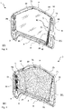
Figure 1 is a schematic perspective view of an embodiment of the device for screening a window of a vehicle according to the invention; -
Figure 2 is a schematic perspective view of an enlarged detail of the device ofFigure 1 ; -
Figures 3 and 4 are a schematic axonometric view of two different configurations of use of the device ofFigure 1 . - With reference to the accompanying drawings, the
numeral 1 denotes in its entirety a device for screening a window F of a vehicle V made in accordance with the invention, hereinafter also referred to simply as thedevice 1. With reference to the accompanying drawings, thedevice 1 comprises aframe 2, afirst rail 3 and ascreen 4. Theframe 2 of thedevice 1 is stably engaged with the vehicle V. - For example, the
frame 2 is engaged with the vehicle V by means ofscrew 20. - The
screws 20 define for thedevice 1 means for locking theframe 2 to the vehicle V. - The
frame 2 comprises a first upright 21, and a second upright 22. - The term "upright" means a structural element with a substantially vertical extension relative to the ground. A first 23 and a second 24 transversal element are positioned transversally to the first 21 and to the second 22 upright, in such a way as to define a supporting structure to be stably fixed to the vehicle V, as illustrated in
Figure 1 . - For example, the
frame 2 is arranged on the window of a door or a hatchback of the vehicle V. - Advantageously, one of either the first 21 or the second 22 upright has a containment compartment.
- With reference to the accompanying drawings, the upright 22 has the
containment compartment 221. - The
containment compartment 221 allows thescreen 4 to be stored when it is not used. - With reference to the accompanying drawings, the
containment compartment 221 is made between theframe 2 of thedevice 1 and the frame of the vehicle V. - The
first rail 3 is positioned between the first 21 and the second 22 upright. - The
first rail 3 is at least partly hidden from view by the secondtransversal element 24. - Further, the second
transversal element 24 contributes to supporting thefirst rail 3, to prevent undesired oscillations of thefirst rail 3. - The
first rail 3 advantageously has an oval cross-section to prevent thescreen 4 from tilting in a direction of rotation coinciding with thefirst rail 3. - In other words, this prevents the
screen 4 from oscillating, or even tipping over, towards the inside, or towards the outside, of the window F. - The
screen 4 is of the retractable type, in such a way that it can be easily stored, occupying a relatively small space. - In this regard, the screen is made of materials chosen from among plastic, elastic, textile materials or a combination of these, such as to withstand a fatigue stress for a predetermined number of screen opening and closing cycles.
- Advantageously, the
screen 4 is made of materials such as to occupy a limited volume, in such a way as to reduce the total dimensions of thedevice 1. - The
screen 4 comprises afront edge 41 which is free to slide on thefirst rail 3, and arear edge 42 fixed to the second upright 22. - The
screen 4 also comprises anupper edge 43 extending between thefront edge 41 and the second upright 22. Thescreen 4 also comprises alower edge 44, opposite theupper edge 43, for engaging on thefirst rail 3. With reference to the accompanying drawings, thescreen 4 is of the cell-like type. - In other words, the
screen 4 comprises a plurality ofclosed cells 44 in such a way that eachcell 44 defines a sort of tubular structure, as illustrated inFigure 2 . Thescreen 4 advantageously has a concertina shape, like a fan, for facilitating the packing of thescreen 4 when it is closed. - The
device 1 also comprises a connectingrod 5 and abracket 6. - The connecting
rod 5 is hinged with a relativefirst end 51 to thefront edge 41 of thescreen 4, and extends on theupper edge 43. - The connecting
rod 5 engages with theupper edge 43 of thescreen 4 only partly. - In fact, when the screen is closed, the connecting
rod 5 defines part of the closing and lockingsurface SC screen 4 in thecontainment compartment 221. - The closing surface SC is defined by the
front edge 41 and the connectingrod 5 in the first non-operating configuration C, as described below and illustrated inFigure 3 . - The length L of the connecting
rod 5 is determined by the geometrical shape of the window F, as shown inFigure 1 . - More specifically, the height H of the first upright 21 defines the height H' of the
front edge 41. - That is to say, the height H' is equal to the height H except for the tolerances necessary for the correct sliding of the
screen 4 and an adequate engagement of thefront edge 41 with the first upright 21. - The difference between the height HH of the second upright 22 and the height H' of the
front edge 41 defines the length L of the connectingrod 5, except for tolerances necessary for the correct sliding of thescreen 4. - In other words, L = HH - H' = HH - H.
- In that way it is possible to easily adapt the
device 1 to different shapes of the window F. - Geometrically, it would not be possible to use a connecting
rod 5 with length L equal to the length of theupper edge 43, except in the case of a window F with a triangular shape, that is to say, with height H and H' equal to zero, or practically equal to zero. - The
bracket 6 is hinged at asecond end 52 of the connectingrod 5, as illustrated inFigure 2 . Advantageously, thebracket 6 is supported by thescreen 4. - In effect, the
screen 4 comprises at least oneseat 40 for housing thebracket 6, as illustrated inFigure 2 . - More specifically, with reference to the accompanying drawings, the
bracket 6 is inserted in one of thecells 44, for translating in the direction T by sliding within one of thecells 44, as described in more detail below. Thedevice 1 comprises asecond rail 7 configured to engage with part of theupper edge 43 of thescreen 4. In that way, it is supported by thescreen 4 which is thus more easily maintained in position, that is to say, preventing thescreen 4 from tipping and facilitating its sliding. - The
second rail 7 is constrained by a relativefirst end 71 to thesecond upright 22, and by a relativesecond end 72 to theframe 2. - More specifically, the
second end 72 is stably connected to the firsttransversal element 23 of theframe 2, engaging the firsttransversal member 23 only partly. This allows the constructional structure to be simplified and to easily adapt thedevice 1, and more specifically, thescreen 4, to different shapes of the window F. - In use, the
screen 4 is configured to translate on thefirst rail 3 for moving between a first non-operating configuration C, wherein thescreen 4 is entirely positioned inside thecontainment compartment 221, and at least a second operating configuration A, wherein thefront edge 41 is at thefirst upright 21 and thescreen 4 is extended between the first 21 and the second 22 upright. - More specifically,
Figure 3 shows the first non-operative configuration C. - According to this configuration the
screen 4 is placed inside thecontainment compartment 221. - The
front edge 41 and the connectingrod 5 are coplanar and aligned along the same direction so as to define the closing surface SC of thescreen 4 inside thecontainment compartment 221. - In that configuration the
bracket 6 is aligned with the connectingrod 5, in such a way as to occupy as little space as possible. - Starting from the first non-operating configuration C, illustrated in
Figure 3 , thedevice 1 moves to a second operating configuration A, shown inFigure 4 . - In order to move to this configuration, the
screen 4 translates along thefirst rail 3, and thesecond rail 7. - During the passage of the
screen 4 from the first non-operating configuration C to the second operating configuration A, thebracket 6 translates along a direction T transversal to thefirst rail 3 and belonging to the plane defined by theframe 2. - The translation of the
bracket 6 thus allows the rotation of the connectingrod 5 to be determined, in such a way that the connectingrod 5 can be adapted to different configurations of use. - Moreover, the
bracket 6 allows thescreen 4 to be supported and to keep it in position to cover the window F in the second operating configuration A, without thescreen 4 folding bask on itself. - This also prevents accidental breakage of the
screen 4, since it is possible to more easily keep it in position. - During the forward movement of the
screen 4 along thefirst rail 3, the connectingrod 5 also facilitates the driving of thescreen 4, contributing to imparting a force on thefront edge 41. - By pulling the
screen 4 up to thefirst upright 21, the window F is completely covered by thescreen 4, and thus screened. - Subsequently, starting from the second operating configuration A, shown in
Figure 4 , thedevice 1 returns to a first non-operating configuration C, illustrated inFigure 3 . - In that way, the window F is freed from the
screen 4. According to embodiments not illustrated, thecontainment compartment 221 is made in the form of a box-shaped element stably connected to theframe 2. Advantageously, the box-shaped element is applied at one of either the first 21 or the second 22 upright. According to embodiments not illustrated, thescreen 4 is of the heat insulating type, in such a way as to allow both the screening of the window F and the thermal insulation of the vehicle V. - The
device 1 comprises at least one magnet, not illustrated, positioned at least at one between thefirst upright 21 and thesecond upright 22 for firmly fixing thescreen 4 in the second operating configuration A and in the first non-operating configuration C, respectively. - Grips of different types, such as, for example, handles, are positioned on the
screen 4, so as to facilitate the translation along therail 3. - The device for screening a window of a vehicle according to the invention achieves the preset aims and brings important advantages.
- A first advantage of the screening device according to the invention is the possibility of making a device which can be easily adapted to different shapes of the window. Another advantage is the possibility of reducing the risk of breakages of the screen and/or the device after repeated use of the screen.
- A further advantage is due to the fact that the screen may be hidden from view.
- Yet another advantage is due to the possibility of keeping the screen in position, being able to omit, at least partly, the upper rail, or in any case reduce it. Yet another advantage is the possibility of reducing the constructional complexity of a screening device.
Claims (10)
- A device for screening a window (F) of a vehicle (V), comprising:- a frame (2) configured to be stably engaged with said vehicle (V), said frame (2) comprising a first upright (21), and a second upright (22) presenting a containment compartment (221);- a first rail (3) disposed between said first (21) and said second (22) upright;- a retractable screen (4) comprising a front edge (41) free to slide on said first rail (3), and a rear edge (42) attached to said second upright (22), said screen (4) being configured for translating on said first rail (3) for moving between a first non-operating configuration (C), wherein said screen (4) is entirely positioned inside the containment compartment (221), and at least a second operating configuration (A), wherein said front edge (41) is at said first upright (21) and said screen (4) is extended between said first (21) and said second (22) upright, said screen (4) comprising an upper edge (43) extending between said front edge (41) and said second upright (22), characterised in that it further comprises:- a connecting rod (5) hinged with a first end (51) thereof to said front edge (41), and extending on said upper edge (43);- a bracket (6) hinged to a second end (52) of said connecting rod (5), said bracket (6) being configured to translate, according to a direction (T) transversal to said first rail (3) and belonging to the plane defined by said frame (2), during the passage of said screen (4) from said first non-operating configuration (C) to said second operating configuration (A).
- The device according to claim 1, characterised in that said connecting rod (5) engages said upper edge (43) only partly.
- The device according to any one of the preceding claims, characterised in that said bracket (6) is supported by said screen (4).
- The device according to the preceding claim, characterised in that said screen (4) comprises at least one seat (40) for housing said bracket (6) in said seat (40).
- The device according to any one of the preceding claims, characterised in that said screen (4) is of the cell-like type.
- The device according to the preceding claim, characterised in that said screen (4) comprises a plurality of closed cells (44), said bracket (6) being inserted in one of said cells (44) of said plurality, for translating along said direction (T) by sliding within one of said cells (44).
- The device according to any one of the preceding claims, characterised in that it comprises a second rail (7) configured to engage with part of said upper edge (43) of said screen (4), said second rail (7) being constrained by a relative first end (71) to said second upright (22), and by a second end (72) to said frame (2).
- The device according to any one of the preceding claims, characterised in that said first rail (3) has an oval cross section to prevent the tilting of said screen (4) in a direction of rotation coinciding with said first rail (3).
- The device according to any one of the preceding claims, characterised in that it comprises at least one magnet positioned at least at one of said first upright (21) and second upright (22) for firmly fixing said screen (4) respectively in said second operating configuration (A) and in said first non-operating configuration (C).
- The device according to any one of the preceding claims, characterised in that said screen (4) is of the thermally insulating type.
Applications Claiming Priority (1)
| Application Number | Priority Date | Filing Date | Title |
|---|---|---|---|
| IT102021000009542A IT202100009542A1 (en) | 2021-04-15 | 2021-04-15 | DEVICE FOR TINTING A WINDOW OF A VEHICLE |
Publications (2)
| Publication Number | Publication Date |
|---|---|
| EP4074530A1 true EP4074530A1 (en) | 2022-10-19 |
| EP4074530B1 EP4074530B1 (en) | 2024-02-28 |
Family
ID=76708325
Family Applications (1)
| Application Number | Title | Priority Date | Filing Date |
|---|---|---|---|
| EP22165808.1A Active EP4074530B1 (en) | 2021-04-15 | 2022-03-31 | Device for screening a window of a vehicle |
Country Status (3)
| Country | Link |
|---|---|
| US (1) | US20220332172A1 (en) |
| EP (1) | EP4074530B1 (en) |
| IT (1) | IT202100009542A1 (en) |
Citations (3)
| Publication number | Priority date | Publication date | Assignee | Title |
|---|---|---|---|---|
| EP0592855A1 (en) * | 1992-10-15 | 1994-04-20 | GEBR. HAPPICH GmbH | Sun visor for motor vehicles |
| DE29612722U1 (en) * | 1996-07-23 | 1997-05-15 | Hymer Ag | Cab darkening and insulation system |
| CN208021146U (en) * | 2018-02-11 | 2018-10-30 | 周天然 | Automobile side-window curtain fixing bracket |
-
2021
- 2021-04-15 IT IT102021000009542A patent/IT202100009542A1/en unknown
-
2022
- 2022-03-31 EP EP22165808.1A patent/EP4074530B1/en active Active
- 2022-04-12 US US17/718,603 patent/US20220332172A1/en active Pending
Patent Citations (3)
| Publication number | Priority date | Publication date | Assignee | Title |
|---|---|---|---|---|
| EP0592855A1 (en) * | 1992-10-15 | 1994-04-20 | GEBR. HAPPICH GmbH | Sun visor for motor vehicles |
| DE29612722U1 (en) * | 1996-07-23 | 1997-05-15 | Hymer Ag | Cab darkening and insulation system |
| CN208021146U (en) * | 2018-02-11 | 2018-10-30 | 周天然 | Automobile side-window curtain fixing bracket |
Also Published As
| Publication number | Publication date |
|---|---|
| EP4074530B1 (en) | 2024-02-28 |
| IT202100009542A1 (en) | 2022-10-15 |
| US20220332172A1 (en) | 2022-10-20 |
Similar Documents
| Publication | Publication Date | Title |
|---|---|---|
| US6227594B1 (en) | Motor vehicle tailgate mounted to pivot about a horizontal axis in the vicinity of its bottom edge | |
| JP4776786B2 (en) | Convertible vehicle roof | |
| US11752842B2 (en) | Convertible skeleton door | |
| KR20180055633A (en) | Integrated extended bed assembly for vehicle | |
| ES2275540T3 (en) | REMOVABLE COVER MODULE OF A CAR VEHICLE AND AUTOMOBILE VEHICLE EQUIPPED WITH SUCH MODULE. | |
| CA1133540A (en) | Window structure for vehicles | |
| EP4074530B1 (en) | Device for screening a window of a vehicle | |
| US6296295B1 (en) | Motor vehicle with a convertible top | |
| RU2038232C1 (en) | Body rear part | |
| EP2113420B1 (en) | Tonneau cover apparatus for an automobile | |
| EP2460686B1 (en) | Vehicle table and vehicle fridge housing integrating the table, in particular for industrial or commercial vehicles | |
| EP0952019A1 (en) | Door module | |
| JPH0376253B2 (en) | ||
| KR102417392B1 (en) | Map pocket assembly for door openable upward | |
| US20160059683A1 (en) | Rear vehicle-body structure of vehicle | |
| KR100380444B1 (en) | Opening and shutting device middle gate and middle gate door glass for vehicle | |
| RU2794572C2 (en) | Door for pickup truck | |
| KR102026554B1 (en) | sun-visor for car | |
| EP3381772B1 (en) | Side wall for a cargo area with improved latching or locking mechanism | |
| JPH0678039U (en) | Mounting structure for movable roof panel drive | |
| US20130001976A1 (en) | Visor system for open-roof vehicles | |
| WO2020218990A1 (en) | Caravan in a new superstructure form for pickup vehicles | |
| KR0182239B1 (en) | Trunk lid holder | |
| DE102006047558A1 (en) | Automobile has rear hatch with integral internal fold-down external baggage rack | |
| RU11152U1 (en) | ARMORED CAR DOOR DOOR |
Legal Events
| Date | Code | Title | Description |
|---|---|---|---|
| PUAI | Public reference made under article 153(3) epc to a published international application that has entered the european phase |
Free format text: ORIGINAL CODE: 0009012 |
|
| STAA | Information on the status of an ep patent application or granted ep patent |
Free format text: STATUS: THE APPLICATION HAS BEEN PUBLISHED |
|
| AK | Designated contracting states |
Kind code of ref document: A1 Designated state(s): AL AT BE BG CH CY CZ DE DK EE ES FI FR GB GR HR HU IE IS IT LI LT LU LV MC MK MT NL NO PL PT RO RS SE SI SK SM TR |
|
| STAA | Information on the status of an ep patent application or granted ep patent |
Free format text: STATUS: REQUEST FOR EXAMINATION WAS MADE |
|
| 17P | Request for examination filed |
Effective date: 20221107 |
|
| RBV | Designated contracting states (corrected) |
Designated state(s): AL AT BE BG CH CY CZ DE DK EE ES FI FR GB GR HR HU IE IS IT LI LT LU LV MC MK MT NL NO PL PT RO RS SE SI SK SM TR |
|
| P01 | Opt-out of the competence of the unified patent court (upc) registered |
Effective date: 20230522 |
|
| GRAP | Despatch of communication of intention to grant a patent |
Free format text: ORIGINAL CODE: EPIDOSNIGR1 |
|
| STAA | Information on the status of an ep patent application or granted ep patent |
Free format text: STATUS: GRANT OF PATENT IS INTENDED |
|
| INTG | Intention to grant announced |
Effective date: 20230926 |
|
| GRAS | Grant fee paid |
Free format text: ORIGINAL CODE: EPIDOSNIGR3 |
|
| GRAA | (expected) grant |
Free format text: ORIGINAL CODE: 0009210 |
|
| STAA | Information on the status of an ep patent application or granted ep patent |
Free format text: STATUS: THE PATENT HAS BEEN GRANTED |
|
| AK | Designated contracting states |
Kind code of ref document: B1 Designated state(s): AL AT BE BG CH CY CZ DE DK EE ES FI FR GB GR HR HU IE IS IT LI LT LU LV MC MK MT NL NO PL PT RO RS SE SI SK SM TR |
|
| REG | Reference to a national code |
Ref country code: GB Ref legal event code: FG4D |
|
| REG | Reference to a national code |
Ref country code: CH Ref legal event code: EP |
|
| REG | Reference to a national code |
Ref country code: DE Ref legal event code: R096 Ref document number: 602022002100 Country of ref document: DE |
|
| REG | Reference to a national code |
Ref country code: IE Ref legal event code: FG4D |