EP4074402B1 - A dryer having improved filter - Google Patents
A dryer having improved filter Download PDFInfo
- Publication number
- EP4074402B1 EP4074402B1 EP22159232.2A EP22159232A EP4074402B1 EP 4074402 B1 EP4074402 B1 EP 4074402B1 EP 22159232 A EP22159232 A EP 22159232A EP 4074402 B1 EP4074402 B1 EP 4074402B1
- Authority
- EP
- European Patent Office
- Prior art keywords
- filter
- dryer
- layer
- spacer
- air
- Prior art date
- Legal status (The legal status is an assumption and is not a legal conclusion. Google has not performed a legal analysis and makes no representation as to the accuracy of the status listed.)
- Active
Links
- 125000006850 spacer group Chemical group 0.000 claims description 37
- 239000004744 fabric Substances 0.000 claims description 22
- 238000010028 chemical finishing Methods 0.000 claims description 6
- 229920002994 synthetic fiber Polymers 0.000 claims description 5
- 239000000203 mixture Substances 0.000 claims description 3
- 239000000835 fiber Substances 0.000 description 13
- 238000001914 filtration Methods 0.000 description 13
- 238000000034 method Methods 0.000 description 9
- 238000004140 cleaning Methods 0.000 description 7
- 230000007423 decrease Effects 0.000 description 6
- 239000000463 material Substances 0.000 description 6
- 230000003670 easy-to-clean Effects 0.000 description 4
- XLYOFNOQVPJJNP-UHFFFAOYSA-N water Substances O XLYOFNOQVPJJNP-UHFFFAOYSA-N 0.000 description 4
- 230000000844 anti-bacterial effect Effects 0.000 description 3
- 230000035699 permeability Effects 0.000 description 3
- 230000002940 repellent Effects 0.000 description 3
- 239000005871 repellent Substances 0.000 description 3
- 239000004753 textile Substances 0.000 description 3
- 238000005265 energy consumption Methods 0.000 description 2
- 238000009940 knitting Methods 0.000 description 2
- 238000004519 manufacturing process Methods 0.000 description 2
- 229920000728 polyester Polymers 0.000 description 2
- 239000011148 porous material Substances 0.000 description 2
- 238000009941 weaving Methods 0.000 description 2
- RNFJDJUURJAICM-UHFFFAOYSA-N 2,2,4,4,6,6-hexaphenoxy-1,3,5-triaza-2$l^{5},4$l^{5},6$l^{5}-triphosphacyclohexa-1,3,5-triene Chemical compound N=1P(OC=2C=CC=CC=2)(OC=2C=CC=CC=2)=NP(OC=2C=CC=CC=2)(OC=2C=CC=CC=2)=NP=1(OC=1C=CC=CC=1)OC1=CC=CC=C1 RNFJDJUURJAICM-UHFFFAOYSA-N 0.000 description 1
- 241000894006 Bacteria Species 0.000 description 1
- 239000004952 Polyamide Substances 0.000 description 1
- 239000004698 Polyethylene Substances 0.000 description 1
- 239000004743 Polypropylene Substances 0.000 description 1
- 238000010521 absorption reaction Methods 0.000 description 1
- 230000002411 adverse Effects 0.000 description 1
- 238000001311 chemical methods and process Methods 0.000 description 1
- 238000004040 coloring Methods 0.000 description 1
- 230000003247 decreasing effect Effects 0.000 description 1
- 230000006866 deterioration Effects 0.000 description 1
- 238000001035 drying Methods 0.000 description 1
- 239000000975 dye Substances 0.000 description 1
- 230000000694 effects Effects 0.000 description 1
- 238000000605 extraction Methods 0.000 description 1
- 239000003063 flame retardant Substances 0.000 description 1
- 230000002209 hydrophobic effect Effects 0.000 description 1
- 238000005470 impregnation Methods 0.000 description 1
- 230000003993 interaction Effects 0.000 description 1
- 239000007788 liquid Substances 0.000 description 1
- 230000007774 longterm Effects 0.000 description 1
- 238000010297 mechanical methods and process Methods 0.000 description 1
- 239000004745 nonwoven fabric Substances 0.000 description 1
- 239000002245 particle Substances 0.000 description 1
- 230000008447 perception Effects 0.000 description 1
- 229920002647 polyamide Polymers 0.000 description 1
- -1 polypropylene Polymers 0.000 description 1
- 229920001155 polypropylene Polymers 0.000 description 1
- 239000002994 raw material Substances 0.000 description 1
- 230000001105 regulatory effect Effects 0.000 description 1
- 238000003860 storage Methods 0.000 description 1
- 239000012209 synthetic fiber Substances 0.000 description 1
- 230000000007 visual effect Effects 0.000 description 1
- 238000004804 winding Methods 0.000 description 1
- 239000002759 woven fabric Substances 0.000 description 1
Images

Classifications
-
- D—TEXTILES; PAPER
- D06—TREATMENT OF TEXTILES OR THE LIKE; LAUNDERING; FLEXIBLE MATERIALS NOT OTHERWISE PROVIDED FOR
- D06F—LAUNDERING, DRYING, IRONING, PRESSING OR FOLDING TEXTILE ARTICLES
- D06F58/00—Domestic laundry dryers
- D06F58/20—General details of domestic laundry dryers
- D06F58/22—Lint collecting arrangements
-
- B—PERFORMING OPERATIONS; TRANSPORTING
- B01—PHYSICAL OR CHEMICAL PROCESSES OR APPARATUS IN GENERAL
- B01D—SEPARATION
- B01D39/00—Filtering material for liquid or gaseous fluids
- B01D39/08—Filter cloth, i.e. woven, knitted or interlaced material
- B01D39/083—Filter cloth, i.e. woven, knitted or interlaced material of organic material
-
- D—TEXTILES; PAPER
- D04—BRAIDING; LACE-MAKING; KNITTING; TRIMMINGS; NON-WOVEN FABRICS
- D04B—KNITTING
- D04B21/00—Warp knitting processes for the production of fabrics or articles not dependent on the use of particular machines; Fabrics or articles defined by such processes
- D04B21/14—Fabrics characterised by the incorporation by knitting, in one or more thread, fleece, or fabric layers, of reinforcing, binding, or decorative threads; Fabrics incorporating small auxiliary elements, e.g. for decorative purposes
- D04B21/16—Fabrics characterised by the incorporation by knitting, in one or more thread, fleece, or fabric layers, of reinforcing, binding, or decorative threads; Fabrics incorporating small auxiliary elements, e.g. for decorative purposes incorporating synthetic threads
-
- B—PERFORMING OPERATIONS; TRANSPORTING
- B01—PHYSICAL OR CHEMICAL PROCESSES OR APPARATUS IN GENERAL
- B01D—SEPARATION
- B01D2239/00—Aspects relating to filtering material for liquid or gaseous fluids
- B01D2239/04—Additives and treatments of the filtering material
- B01D2239/0442—Antimicrobial, antibacterial, antifungal additives
-
- B—PERFORMING OPERATIONS; TRANSPORTING
- B01—PHYSICAL OR CHEMICAL PROCESSES OR APPARATUS IN GENERAL
- B01D—SEPARATION
- B01D2239/00—Aspects relating to filtering material for liquid or gaseous fluids
- B01D2239/06—Filter cloth, e.g. knitted, woven non-woven; self-supported material
- B01D2239/065—More than one layer present in the filtering material
-
- B—PERFORMING OPERATIONS; TRANSPORTING
- B01—PHYSICAL OR CHEMICAL PROCESSES OR APPARATUS IN GENERAL
- B01D—SEPARATION
- B01D2239/00—Aspects relating to filtering material for liquid or gaseous fluids
- B01D2239/12—Special parameters characterising the filtering material
- B01D2239/1208—Porosity
-
- D—TEXTILES; PAPER
- D10—INDEXING SCHEME ASSOCIATED WITH SUBLASSES OF SECTION D, RELATING TO TEXTILES
- D10B—INDEXING SCHEME ASSOCIATED WITH SUBLASSES OF SECTION D, RELATING TO TEXTILES
- D10B2401/00—Physical properties
- D10B2401/13—Physical properties anti-allergenic or anti-bacterial
-
- D—TEXTILES; PAPER
- D10—INDEXING SCHEME ASSOCIATED WITH SUBLASSES OF SECTION D, RELATING TO TEXTILES
- D10B—INDEXING SCHEME ASSOCIATED WITH SUBLASSES OF SECTION D, RELATING TO TEXTILES
- D10B2403/00—Details of fabric structure established in the fabric forming process
- D10B2403/02—Cross-sectional features
- D10B2403/021—Lofty fabric with equidistantly spaced front and back plies, e.g. spacer fabrics
-
- D—TEXTILES; PAPER
- D10—INDEXING SCHEME ASSOCIATED WITH SUBLASSES OF SECTION D, RELATING TO TEXTILES
- D10B—INDEXING SCHEME ASSOCIATED WITH SUBLASSES OF SECTION D, RELATING TO TEXTILES
- D10B2505/00—Industrial
- D10B2505/04—Filters
Definitions
- the present invention relates to a dryer with preferably a heat pump having an improved filter.
- the drying air leaving the fan in household dryers follows an air duct and passes over the laundry or textile and leaves the fluff and fibers therein by means of a filter.
- Different types of filter fabrics are used for said filtering process. Basically, they are divided into two as manufactured from woven and non-woven surface. In the case of woven fabric filters, users are requested by the manufacturer to clean the filter in front of the door at the end of each cycle, and the filter in front of the heat exchanger, typically every six months.
- the reason why the filter in front of the door is to be cleaned every cycle is that the filter manufactured from woven textile performs two-dimensional filtering, and the filter pores are clogged at the end of a single cycle, causing problems such as energy regime deterioration and failure to dry in other cycles.
- the reason why the front of the heat exchanger is cleaned every six months is that the fibers smaller than the pore size of the existing filter in front of the door passes through and accumulate in front of the heat exchanger.
- a dryer comprising a fabric filter having one property from the group of hydrophobic, dirt repellent and antibacterial fabric, and which is connected to a carrier.
- the aim of the present invention is the realization of a dryer comprising an easy-to-clean fluff filter which has both high filtering and air-permeability performance, and high strength.
- the dryer preferably with a heat pump, realized in order to attain the aim of the present invention and explicated in the claims, comprises a body and an air duct which is disposed in the body so as to ensure the circulation of the air during the air cycle.
- Said air duct contains all the sub-components through which the process air passes such as front bearing housing, area in front of or behind the heat exchanger, the air flow duct, the drum inlet and outlet, and forms an air flow path to direct the air.
- the dryer comprises a filter disposed in the air duct perpendicularly to the air flow direction and having a breathable upper layer which is manufactured from fabric, a breathable lower layer which is manufactured from fabric and which is positioned parallel to and at a distance from the upper layer, and a spacer layer in the form of spacer yarns which is disposed between the lower layer and the upper layer and which ensures air passage.
- the fabrics forming the lower and upper layers can be manufactured by knitting or weaving.
- the dryer comprises the filter having the upper layer which has a lower porosity than or equal porosity to the lower layer.
- the upper layer is considered as the first surface encountered by the process air in the dryer while entering the filter, a more efficient filtering performance is provided with less air flow loss by means of the upper layer having a lower or equal porosity with respect to the lower layer.
- the dryer comprises the filter having the spacer layer with spacer yarns arranged as crosswise (XX), parallel to each other (II) or as a crosswise-parallel mixture.
- XX crosswise
- said structures may have parallel (II) spacer yarns where the fluff is heavily collected and crosswise (XX) spacer yarns where the fluff is lightly collected.
- the dryer comprises the filter having the spacer layer with spacer yarns composed of monofilaments or multifilaments with a maximum diameter of 0.3 mm.
- the dryer comprises the filter having the lower layer and/or upper layer composed of monofilament or fully-drawn-yarn (FDY) multifilaments.
- FDY fully-drawn-yarn
- the dryer comprises the filter having the lower layer and/or upper layer treated with chemical finishing.
- the surface slipperiness is further increased, and the user is provided with an easier-to-clean product.
- the dryer comprises the filter having the spacer layer with spacer yarns manufactured from synthetic material.
- the horizontal air-permeability and the impact resistance are improved.
- the dryer comprises a filter which is disposed in front of or behind the heat exchanger in the air duct.
- a filter which is disposed in front of or behind the heat exchanger in the air duct.
- the dryer (1) preferably with a heat pump, comprises a body (2) and an air duct (3) which is disposed in the body (2) and which provides the air circulation during the air cycle.
- Said air duct (3) contains all the sub-components through which the process air passes such as front bearing housing, area in the front or at the rear of the heat exchanger, the air flow duct, the drum inlet and outlet, and forms an air flow path to direct the air.
- the dryer (1) comprises a filter (7) disposed in the air duct (3) perpendicularly to the air flow direction and having a breathable upper layer (4) which is manufactured from fabric, a breathable lower layer (5) which is manufactured from fabric and which is positioned parallel to and at a distance from the upper layer (4), and a spacer layer (6) in the form of spacer yarns which is disposed between the lower layer (5) and the upper layer (4) and which ensures air passage.
- the fabrics forming the lower layer (5) and the upper layer (4) can be manufactured by knitting or weaving.
- said filter (7) can be placed at various regions (front bearing housing, area in front of or behind the heat exchanger, air flow duct, drum inlet and outlet) of the dryer in order to retain the fluff and fibers breaking off from the laundry.
- Said three-layered structure known as 3D (spacer) fabric can be manufactured from warp- or weft-knitted fabric arranged at intervals and parallel to each other, and the yarns used can be antibacterial. Basically, the humid air together with the fluff and fibers therein circulating during the cycle of the dryer (1) encounters first the upper layer (4) of said filter (7).
- the dryer (1) comprises the filter (7) having the upper layer (4) which has a lower porosity than or equal porosity to the lower layer (5).
- the surface the air carrying the fluff enters must be knitted or woven with denser or equal intervals with respect to the surface the air exits.
- the air flow therein is regulated according to the optimal performance.
- the upper layer (4) is considered as the first surface encountered by the process air in the dryer (1) while entering the filter (7), a more efficient filtering performance is provided by means of the upper layer (4) having a lower or equal porosity with respect to the lower layer (5).
- the dryer (1) comprises the filter (7) having the spacer layer (6) with spacer yarns arranged as crosswise (XX), parallel to each other (II) or as a crosswise-parallel mixture.
- the fibers collected in the spacer layer (6) can be easily removed or cleaned.
- the crosswise or parallel arrangement of yarns in the filter (7) may change with various combinations.
- the air flow losses are minimized thanks to the 3D fabric structure.
- the filaments can be placed parallel or obliquely to the air flow direction.
- said structures may have parallel (II) spacer yarns where the fluff is heavily collected and crosswise (XX) spacer yarns where the fluff is lightly collected.
- the dryer (1) comprises the filter (7) having the spacer layer (6) with spacer yarns composed of monofilaments or multifilaments with a maximum diameter of 0.3 mm. While monofilament yarns are manufactured from a single filament of certain thickness, multifilament yarns are formed by twisting many yarns together. Monofilament yarns have low cost and flexibility while multifilament yarns are structures with relatively higher strength compared to textured or monofilament yarns. The tests show that the filaments manufactured with a thickness beyond the above-mentioned value adversely affect the air flow in the spacer layer (6) and cause a decrease in performance in terms of easy cleaning.
- the dryer (1) comprises the filter (7) having the lower layer (5) and/or upper layer (4) composed of monofilament or fully-drawn-yarn (FDY) multifilaments.
- Fully drawn yarns which are formed with a special production technique for the production of multifilament yarns, are mostly obtained by drawing synthetic fibers at high winding speeds in industry. The resistance of fully drawn yarns to physical processes such as elongation and shrinkage is low.
- the fully drawn yarns (FDY) which can be used in both layers, are less bulky and less porous than textured yarns, another multifilament type. Thanks to these features, the necessary compactness between the filaments is provided and fiber passage is prevented.
- the dryer (1) comprises the filter (7) having the lower layer (5) and/or upper layer (4) treated with chemical finishing. Finishing typically covers all the mechanical and chemical processes that the textile material undergoes after pretreatment and coloring processes. Chemical finishing processes, which have many types such as softness, slipperiness, hard gripping, fullness, brightness, dirt repellent, water repellent, flame retardant, are used depending on the structure of the materials. After the chemical finishing is dissolved in a liquid, it is transferred to the material in a finishing machine working with the impregnation or extraction method. Thus, the surface slipperiness is further increased, and the user is provided with an easier-to-clean product. It is also possible to use antibacterial chemical finishing or yarn in order to prevent the fluff and fibers remaining in the filter (7) from generating odor and bacteria.
- the dryer (1) comprises the filter (7) having the spacer layer (6) with spacer yarns manufactured from synthetic material.
- Spacer yarns manufactured from raw materials such as polyester, polypropylene, polyamide and PE increase the physical resistance against water and air interaction.
- Synthetic material can also be manufactured from recycled polyester, PLA, PE materials for sustainability. In both cases, the material strength required in the filter (7) is provided.
- the dryer (1) comprises a filter (7) which is disposed in front of or behind the heat exchanger in the air duct (3).
- a filter (7) which is disposed in front of or behind the heat exchanger in the air duct (3).
- the surface porosity is adjusted such that the air permeability is ⁇ 7000 mm/s at a test area of 20 cm 2 and under 100 Pa pressure. It has a strength value greater than 3 kPa in order to prevent the fabrics from being crushed during cleaning and use, to preserve their form and to ensure a longer economic life.
- the filter (7) can be manufactured from colored yarns or dyed with high-fastness dyes such that the lower layer (5) and the upper layer (4) can be distinguished more easily by the user and the quality perception is increased.
- a dryer (1) comprising a filter (7) which can be used in all types of dryers (vented, condenser, heat pump, hybrid), which can be placed into the dryer (1) in order to retain the fluff breaking off from the laundry (any place such as front bearing housing, area in front of or behind the heat exchanger, the drum inlet and outlet) and which has an improved filtering and cleaning performance.
- a filter (7) which can be used in all types of dryers (vented, condenser, heat pump, hybrid), which can be placed into the dryer (1) in order to retain the fluff breaking off from the laundry (any place such as front bearing housing, area in front of or behind the heat exchanger, the drum inlet and outlet) and which has an improved filtering and cleaning performance.
Description
- The present invention relates to a dryer with preferably a heat pump having an improved filter.
- The drying air leaving the fan in household dryers, especially the dryers with heat pumps, follows an air duct and passes over the laundry or textile and leaves the fluff and fibers therein by means of a filter. Different types of filter fabrics are used for said filtering process. Basically, they are divided into two as manufactured from woven and non-woven surface. In the case of woven fabric filters, users are requested by the manufacturer to clean the filter in front of the door at the end of each cycle, and the filter in front of the heat exchanger, typically every six months. The reason why the filter in front of the door is to be cleaned every cycle is that the filter manufactured from woven textile performs two-dimensional filtering, and the filter pores are clogged at the end of a single cycle, causing problems such as energy regime deterioration and failure to dry in other cycles. The reason why the front of the heat exchanger is cleaned every six months is that the fibers smaller than the pore size of the existing filter in front of the door passes through and accumulate in front of the heat exchanger.
- On the other hand, in the case of non-woven fabrics, it is not necessary to clean the filter at the end of each cycle. Typically, at the end of seven cycles, the filter manufactured from non-woven surface in the form of a bag is expected to be removed and discarded by the user. However, the strength of non-woven surface fabrics is naturally low such that problems such as disintegration, tearing and damage can be encountered during the cycle. Even though the fluff and fiber retaining ability is high in filters manufactured from non-woven surface fabrics, a poor performance is obtained in filtering small particles and leakage is observed. Therefore, the heat exchanger area also gets dirty in this fabric type, and it is not considered suitable for long-term use. Due to such disadvantages in the state of the art, the user satisfaction decreases and the quality criteria cannot be met due to increasing service costs. Although there is a need for an easy-to-clean filter structure with high filtering performance and high strength in the dryers considering all these trade-offs, there is no such embodiment in the state of the art.
- In the state of the art International Patent Document No.
WO2020133299A1 , a 3D fabric filter is disclosed, which is composed of various layers and which has improved water absorption and storage capabilities. - Documents
US 2008/282569 A1 ,WO 2009/133023 A1 andUS 2011/167662 A1 , each discloses an air dryer comprising a filter in the air duct. - In the state of the art European Patent Document No.
EP2334864B1 , a dryer is disclosed, comprising a fabric filter having one property from the group of hydrophobic, dirt repellent and antibacterial fabric, and which is connected to a carrier. - The aim of the present invention is the realization of a dryer comprising an easy-to-clean fluff filter which has both high filtering and air-permeability performance, and high strength.
- The dryer, preferably with a heat pump, realized in order to attain the aim of the present invention and explicated in the claims, comprises a body and an air duct which is disposed in the body so as to ensure the circulation of the air during the air cycle. Said air duct contains all the sub-components through which the process air passes such as front bearing housing, area in front of or behind the heat exchanger, the air flow duct, the drum inlet and outlet, and forms an air flow path to direct the air. The dryer comprises a filter disposed in the air duct perpendicularly to the air flow direction and having a breathable upper layer which is manufactured from fabric, a breathable lower layer which is manufactured from fabric and which is positioned parallel to and at a distance from the upper layer, and a spacer layer in the form of spacer yarns which is disposed between the lower layer and the upper layer and which ensures air passage. The fabrics forming the lower and upper layers can be manufactured by knitting or weaving. By means of said three-layered structure known as 3D (spacer) fabric, a high filtering performance is obtained with minimal air flow losses with respect to 2D fabrics during the cycle in the dryer, and high strength is ensured which provides a long economic life. Moreover, since the air flow loss is low, the energy consumption of the dryer accordingly decreases, providing energy efficiency.
- In an embodiment of the present invention, the dryer comprises the filter having the upper layer which has a lower porosity than or equal porosity to the lower layer. When the upper layer is considered as the first surface encountered by the process air in the dryer while entering the filter, a more efficient filtering performance is provided with less air flow loss by means of the upper layer having a lower or equal porosity with respect to the lower layer.
- In an embodiment of the present invention, the dryer comprises the filter having the spacer layer with spacer yarns arranged as crosswise (XX), parallel to each other (II) or as a crosswise-parallel mixture. Thus, the fibers collected in the spacer layer can be easily removed or cleaned. Preferably, depending on the location of the filter in the dryer, said structures may have parallel (II) spacer yarns where the fluff is heavily collected and crosswise (XX) spacer yarns where the fluff is lightly collected.
- In an embodiment of the present invention, the dryer comprises the filter having the spacer layer with spacer yarns composed of monofilaments or multifilaments with a maximum diameter of 0.3 mm. The tests show that the filaments manufactured with a thickness beyond the above-mentioned value cause a decrease in performance in terms of flow rate and easy cleaning.
- In an embodiment of the present invention, the dryer comprises the filter having the lower layer and/or upper layer composed of monofilament or fully-drawn-yarn (FDY) multifilaments. Thus, the adherence of the fluff and fibers accumulating on the surface decreases, which in turn increases the surface slipperiness, and user is provided with an easy-to-clean product.
- In an embodiment of the present invention, the dryer comprises the filter having the lower layer and/or upper layer treated with chemical finishing. Thus, the surface slipperiness is further increased, and the user is provided with an easier-to-clean product.
- In another embodiment of the present invention, the dryer comprises the filter having the spacer layer with spacer yarns manufactured from synthetic material. By means of the layer manufactured said material, the horizontal air-permeability and the impact resistance are improved.
- In another embodiment of the present invention, the dryer comprises a filter which is disposed in front of or behind the heat exchanger in the air duct. Thus, any fiber leaking to the heat exchanger which is disposed in the dryer is prevented, and the filter cleaning frequency which is once every six months is extended by two-fold (once every twelve months).
- A dryer realized in order to attain the aim of the present invention is illustrated in the attached figures, where:
-
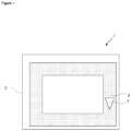
Figure 1 - is the representative schematic view of the dryer. -
Figure 2 - is the schematic side view of the filter. - The elements illustrated in the figures are numbered as follows:
- 1. Dryer
- 2. Body
- 3. Air duct
- 4. Upper layer
- 5. Lower layer
- 6. Spacer layer
- 7. Filter
- The dryer (1), preferably with a heat pump, comprises a body (2) and an air duct (3) which is disposed in the body (2) and which provides the air circulation during the air cycle. Said air duct (3) contains all the sub-components through which the process air passes such as front bearing housing, area in the front or at the rear of the heat exchanger, the air flow duct, the drum inlet and outlet, and forms an air flow path to direct the air. The dryer (1) comprises a filter (7) disposed in the air duct (3) perpendicularly to the air flow direction and having a breathable upper layer (4) which is manufactured from fabric, a breathable lower layer (5) which is manufactured from fabric and which is positioned parallel to and at a distance from the upper layer (4), and a spacer layer (6) in the form of spacer yarns which is disposed between the lower layer (5) and the upper layer (4) and which ensures air passage. The fabrics forming the lower layer (5) and the upper layer (4) can be manufactured by knitting or weaving. In all dryer types (vented, condenser, heat pump, hybrid), said filter (7) can be placed at various regions (front bearing housing, area in front of or behind the heat exchanger, air flow duct, drum inlet and outlet) of the dryer in order to retain the fluff and fibers breaking off from the laundry. Said three-layered structure known as 3D (spacer) fabric can be manufactured from warp- or weft-knitted fabric arranged at intervals and parallel to each other, and the yarns used can be antibacterial. Basically, the humid air together with the fluff and fibers therein circulating during the cycle of the dryer (1) encounters first the upper layer (4) of said filter (7). Especially by means of the spacer yarns which are heavily arranged at the spacer layer (6), a high filtering performance is obtained, and the humid process air is filtered last by the lower layer (5) and then continues its circulation. The need for cleaning the filter (7) after each use is eliminated, and it is sufficient to clean only the filter (7) positioned in front of the heat exchanger once every twelve months at the earliest manually or with water, brush, wet wipe or vacuum cleaner. Thus, a high filtering performance is obtained with minimal air flow losses during the cycle in the dryer (1), and high strength is ensured which provides a long economic life. Moreover, since the air flow loss is low by means of the channeled, gapped and porous structure of the filter (7), the energy consumption caused by the dryer (1) air cycle is accordingly decreased, providing energy efficiency.
- In an embodiment of the present invention, the dryer (1) comprises the filter (7) having the upper layer (4) which has a lower porosity than or equal porosity to the lower layer (5). In other words, the surface the air carrying the fluff enters must be knitted or woven with denser or equal intervals with respect to the surface the air exits. Thus, the air flow therein is regulated according to the optimal performance. When the upper layer (4) is considered as the first surface encountered by the process air in the dryer (1) while entering the filter (7), a more efficient filtering performance is provided by means of the upper layer (4) having a lower or equal porosity with respect to the lower layer (5).
- In an embodiment of the present invention, the dryer (1) comprises the filter (7) having the spacer layer (6) with spacer yarns arranged as crosswise (XX), parallel to each other (II) or as a crosswise-parallel mixture. Thus, the fibers collected in the spacer layer (6) can be easily removed or cleaned. Depending on the need, the crosswise or parallel arrangement of yarns in the filter (7) may change with various combinations. Especially, in the parallel type arrangement, the air flow losses are minimized thanks to the 3D fabric structure. Depending on the desired technical effect, the filaments can be placed parallel or obliquely to the air flow direction. Preferably, depending on the location of the filter in the dryer, said structures may have parallel (II) spacer yarns where the fluff is heavily collected and crosswise (XX) spacer yarns where the fluff is lightly collected.
- In an embodiment of the present invention, the dryer (1) comprises the filter (7) having the spacer layer (6) with spacer yarns composed of monofilaments or multifilaments with a maximum diameter of 0.3 mm. While monofilament yarns are manufactured from a single filament of certain thickness, multifilament yarns are formed by twisting many yarns together. Monofilament yarns have low cost and flexibility while multifilament yarns are structures with relatively higher strength compared to textured or monofilament yarns. The tests show that the filaments manufactured with a thickness beyond the above-mentioned value adversely affect the air flow in the spacer layer (6) and cause a decrease in performance in terms of easy cleaning.
- In an embodiment of the present invention, the dryer (1) comprises the filter (7) having the lower layer (5) and/or upper layer (4) composed of monofilament or fully-drawn-yarn (FDY) multifilaments. Fully drawn yarns, which are formed with a special production technique for the production of multifilament yarns, are mostly obtained by drawing synthetic fibers at high winding speeds in industry. The resistance of fully drawn yarns to physical processes such as elongation and shrinkage is low. On the other hand, the fully drawn yarns (FDY), which can be used in both layers, are less bulky and less porous than textured yarns, another multifilament type. Thanks to these features, the necessary compactness between the filaments is provided and fiber passage is prevented. Moreover, the adherence of the fluff and fibers accumulating on the filter (7) surface decreases, which in turn increases the surface slipperiness, and user is provided with an easy-to-clean product. On the other hand, with the use of monofilament yarn in the lower (5) and/or upper layer (4), a structure with less volume, higher air permeability, lower filtering performance, relatively high rigidity and a rough surface is obtained. Similar to fully drawn multifilaments, it is less bulky and has higher air permeability than textured yarns. Thus, air flow loss is very low compared to other multifilament yarns. In terms of filtering performance and surface slipperiness, it has a lower performance than fully drawn multifilament yarns.
- In an embodiment of the present invention, the dryer (1) comprises the filter (7) having the lower layer (5) and/or upper layer (4) treated with chemical finishing. Finishing typically covers all the mechanical and chemical processes that the textile material undergoes after pretreatment and coloring processes. Chemical finishing processes, which have many types such as softness, slipperiness, hard gripping, fullness, brightness, dirt repellent, water repellent, flame retardant, are used depending on the structure of the materials. After the chemical finishing is dissolved in a liquid, it is transferred to the material in a finishing machine working with the impregnation or extraction method. Thus, the surface slipperiness is further increased, and the user is provided with an easier-to-clean product. It is also possible to use antibacterial chemical finishing or yarn in order to prevent the fluff and fibers remaining in the filter (7) from generating odor and bacteria.
- In another embodiment of the present invention, the dryer (1) comprises the filter (7) having the spacer layer (6) with spacer yarns manufactured from synthetic material. Spacer yarns manufactured from raw materials such as polyester, polypropylene, polyamide and PE increase the physical resistance against water and air interaction. Synthetic material can also be manufactured from recycled polyester, PLA, PE materials for sustainability. In both cases, the material strength required in the filter (7) is provided.
- In another embodiment of the present invention, the dryer (1) comprises a filter (7) which is disposed in front of or behind the heat exchanger in the air duct (3). Thus, any fiber leak to the heat exchanger which is disposed in the dryer (1) is prevented, and the filter cleaning frequency which is once every six months is extended by two-fold (once every twelve months).
- There are test results which meet the international standards that may be valid in all the embodiments of the present invention and provide the optimum working values of the present invention. For the lower layer (5) and the upper layer (4), the surface porosity is adjusted such that the air permeability is <7000 mm/s at a test area of 20 cm 2 and under 100 Pa pressure. It has a strength value greater than 3 kPa in order to prevent the fabrics from being crushed during cleaning and use, to preserve their form and to ensure a longer economic life. As a visual addition, the filter (7) can be manufactured from colored yarns or dyed with high-fastness dyes such that the lower layer (5) and the upper layer (4) can be distinguished more easily by the user and the quality perception is increased.
- By means of the specially-configured 3D fabric structure of the present invention, a dryer (1) is realized, comprising a filter (7) which can be used in all types of dryers (vented, condenser, heat pump, hybrid), which can be placed into the dryer (1) in order to retain the fluff breaking off from the laundry (any place such as front bearing housing, area in front of or behind the heat exchanger, the drum inlet and outlet) and which has an improved filtering and cleaning performance.
Claims (8)
- A dryer (1) comprising a body (2) and an air duct (3) which is disposed in the body (2) and which provides the air circulation during the air cycle, characterized by a filter (7) disposed in the air duct (3) perpendicularly to the air flow direction and having a breathable upper layer (4) which is manufactured from fabric, a breathable lower layer (5) which is manufactured from fabric and which is positioned parallel to and at a distance from the upper layer (4), and a spacer layer (6) in the form of spacer yarns which is disposed between the lower layer (5) and the upper layer (4) and which ensures air passage.
- A dryer (1) as in Claim 1, characterized by the filter (7) having the upper layer (4) which has a lower porosity than or equal porosity to the lower layer (5).
- A dryer (1) as in Claim 1 or 2, characterized by the filter (7) having the spacer layer (6) with spacer yarns arranged as crosswise (XX), parallel to each other (II) or as a crosswise-parallel mixture.
- A dryer (1) as in any one of the above claims, characterized by the filter (7) having the spacer layer (6) with spacer yarns composed of monofilaments or multifilaments with a maximum diameter of 0.3 mm.
- A dryer (1) as in any one of the above claims, characterized by the filter (7) having the lower layer (5) and/or upper layer (4) composed of monofilament or fully-drawn-yarn multifilaments yarns.
- A dryer (1) as in any one of the above claims, characterized by the filter (7) having the lower layer (5) and/or upper layer (4) treated with chemical finishing.
- A dryer (1) as in any one of the above claims, characterized by the filter (7) having the spacer layer (6) with spacer yarns manufactured from synthetic material.
- A dryer (1) as in any one of the above claims, characterized by a filter (7) which is disposed in front of or behind the heat exchanger in the air duct (3).
Applications Claiming Priority (1)
| Application Number | Priority Date | Filing Date | Title |
|---|---|---|---|
| TR202106454 | 2021-04-12 |
Publications (2)
| Publication Number | Publication Date |
|---|---|
| EP4074402A1 EP4074402A1 (en) | 2022-10-19 |
| EP4074402B1 true EP4074402B1 (en) | 2023-09-06 |
Family
ID=80595125
Family Applications (1)
| Application Number | Title | Priority Date | Filing Date |
|---|---|---|---|
| EP22159232.2A Active EP4074402B1 (en) | 2021-04-12 | 2022-02-28 | A dryer having improved filter |
Country Status (3)
| Country | Link |
|---|---|
| EP (1) | EP4074402B1 (en) |
| ES (1) | ES2965150T3 (en) |
| PL (1) | PL4074402T3 (en) |
Family Cites Families (6)
| Publication number | Priority date | Publication date | Assignee | Title |
|---|---|---|---|---|
| US7766988B2 (en) * | 2007-05-17 | 2010-08-03 | Roberts Paul L | Lint trap liner |
| WO2009133023A1 (en) * | 2008-05-02 | 2009-11-05 | Arcelik Anonim Sirketi | A dryer having a self cleaning lint filter |
| DE102008041998A1 (en) * | 2008-09-11 | 2010-03-18 | BSH Bosch und Siemens Hausgeräte GmbH | Dryer with a lint filter and a cleaning device |
| CN104328597B (en) * | 2014-08-18 | 2016-04-27 | 福建省晋江市华宇织造有限公司 | Three-layer mesh fabric of a kind of weatherability and preparation method thereof |
| US9828705B1 (en) * | 2016-09-28 | 2017-11-28 | Shei Chung Hsin Ind. Co., Ltd. | Multiple-layer knitted fabric for dissipating sweat in dual phases |
| CN109603304A (en) | 2018-12-28 | 2019-04-12 | 苏州聿华企业管理有限公司 | Ventilative 3D screen cloth filter core with water suction water storage function |
-
2022
- 2022-02-28 PL PL22159232.2T patent/PL4074402T3/en unknown
- 2022-02-28 ES ES22159232T patent/ES2965150T3/en active Active
- 2022-02-28 EP EP22159232.2A patent/EP4074402B1/en active Active
Also Published As
| Publication number | Publication date |
|---|---|
| ES2965150T3 (en) | 2024-04-11 |
| EP4074402A1 (en) | 2022-10-19 |
| PL4074402T3 (en) | 2024-02-26 |
Similar Documents
| Publication | Publication Date | Title |
|---|---|---|
| CN101389797B (en) | Towel product | |
| US20170342609A1 (en) | Method of making textile products from hygro material | |
| KR100333125B1 (en) | Method for making fabric with excellent water-transition ability | |
| CN210341268U (en) | Novel spunlace non-woven fabric | |
| CN108543349A (en) | A kind of gradient filtration multilayer spun lacing needle-punched composite and its production technology | |
| US10968544B2 (en) | Process for manufacturing air rich yarn and air rich fabric | |
| EP4074402B1 (en) | A dryer having improved filter | |
| KR19990036042A (en) | Filter cloth and filter | |
| KR100587474B1 (en) | Natural fabric for bed having less nappy property and enforced tensile strength | |
| Park et al. | A study on coarse Hanji yarn manufacturing and properties of the Hanji fabric | |
| KR20100028951A (en) | Pad for steam cleaner | |
| JP6254802B2 (en) | Handkerchief fabric and handkerchief | |
| TR2021006454A2 (en) | A DRYER WITH IMPROVED FILTER | |
| WO2009098725A2 (en) | Cleaning cloth | |
| KR101561033B1 (en) | Excellent Water Absorbent Cleaning Cloth Without Lint Generation | |
| KR100604997B1 (en) | Pile knitting fabrics having stiff fibers area and high-absorbable fibers area and mop thereof | |
| CN111501159A (en) | Washable reusable mask fabric and weaving process thereof | |
| CN213836013U (en) | A clean device of textile fabric for weaving equipment | |
| CN212983222U (en) | Hair removing and leveling device for producing medical protective clothing fabric | |
| KR101609328B1 (en) | Fabrics with cut loop group, manufacturing method of the fabrics and textile goods using the same | |
| CN116356535A (en) | Filter assembly for washing machine | |
| EP3199676B1 (en) | Cleaning cloth produced using a fabric having cut loops | |
| KR101609326B1 (en) | Yarn for Fabrics with cut loop group, manufacturing method of the fabrics and textile goods using the same | |
| CN219523254U (en) | Wool fiber fabric convenient for machine washing | |
| CN208517732U (en) | A kind of textile fabric |
Legal Events
| Date | Code | Title | Description |
|---|---|---|---|
| PUAI | Public reference made under article 153(3) epc to a published international application that has entered the european phase |
Free format text: ORIGINAL CODE: 0009012 |
|
| STAA | Information on the status of an ep patent application or granted ep patent |
Free format text: STATUS: REQUEST FOR EXAMINATION WAS MADE |
|
| 17P | Request for examination filed |
Effective date: 20220228 |
|
| AK | Designated contracting states |
Kind code of ref document: A1 Designated state(s): AL AT BE BG CH CY CZ DE DK EE ES FI FR GB GR HR HU IE IS IT LI LT LU LV MC MK MT NL NO PL PT RO RS SE SI SK SM TR |
|
| REG | Reference to a national code |
Ref country code: DE Ref legal event code: R079 Ref document number: 602022000434 Country of ref document: DE Free format text: PREVIOUS MAIN CLASS: B01D0039160000 Ipc: D04B0021160000 Ref country code: DE Ref legal event code: R079 Ipc: D04B0021160000 |
|
| GRAP | Despatch of communication of intention to grant a patent |
Free format text: ORIGINAL CODE: EPIDOSNIGR1 |
|
| STAA | Information on the status of an ep patent application or granted ep patent |
Free format text: STATUS: GRANT OF PATENT IS INTENDED |
|
| RIC1 | Information provided on ipc code assigned before grant |
Ipc: B01D 39/08 20060101ALI20230526BHEP Ipc: D06F 58/22 20060101ALI20230526BHEP Ipc: D04B 21/16 20060101AFI20230526BHEP |
|
| INTG | Intention to grant announced |
Effective date: 20230615 |
|
| GRAS | Grant fee paid |
Free format text: ORIGINAL CODE: EPIDOSNIGR3 |
|
| GRAA | (expected) grant |
Free format text: ORIGINAL CODE: 0009210 |
|
| STAA | Information on the status of an ep patent application or granted ep patent |
Free format text: STATUS: THE PATENT HAS BEEN GRANTED |
|
| AK | Designated contracting states |
Kind code of ref document: B1 Designated state(s): AL AT BE BG CH CY CZ DE DK EE ES FI FR GB GR HR HU IE IS IT LI LT LU LV MC MK MT NL NO PL PT RO RS SE SI SK SM TR |
|
| REG | Reference to a national code |
Ref country code: GB Ref legal event code: FG4D |
|
| REG | Reference to a national code |
Ref country code: CH Ref legal event code: EP |
|
| REG | Reference to a national code |
Ref country code: IE Ref legal event code: FG4D |
|
| REG | Reference to a national code |
Ref country code: DE Ref legal event code: R096 Ref document number: 602022000434 Country of ref document: DE |
|
| REG | Reference to a national code |
Ref country code: LT Ref legal event code: MG9D |
|
| REG | Reference to a national code |
Ref country code: NL Ref legal event code: MP Effective date: 20230906 |
|
| PG25 | Lapsed in a contracting state [announced via postgrant information from national office to epo] |
Ref country code: GR Free format text: LAPSE BECAUSE OF FAILURE TO SUBMIT A TRANSLATION OF THE DESCRIPTION OR TO PAY THE FEE WITHIN THE PRESCRIBED TIME-LIMIT Effective date: 20231207 |
|
| PG25 | Lapsed in a contracting state [announced via postgrant information from national office to epo] |
Ref country code: SE Free format text: LAPSE BECAUSE OF FAILURE TO SUBMIT A TRANSLATION OF THE DESCRIPTION OR TO PAY THE FEE WITHIN THE PRESCRIBED TIME-LIMIT Effective date: 20230906 Ref country code: RS Free format text: LAPSE BECAUSE OF FAILURE TO SUBMIT A TRANSLATION OF THE DESCRIPTION OR TO PAY THE FEE WITHIN THE PRESCRIBED TIME-LIMIT Effective date: 20230906 Ref country code: NO Free format text: LAPSE BECAUSE OF FAILURE TO SUBMIT A TRANSLATION OF THE DESCRIPTION OR TO PAY THE FEE WITHIN THE PRESCRIBED TIME-LIMIT Effective date: 20231206 Ref country code: LV Free format text: LAPSE BECAUSE OF FAILURE TO SUBMIT A TRANSLATION OF THE DESCRIPTION OR TO PAY THE FEE WITHIN THE PRESCRIBED TIME-LIMIT Effective date: 20230906 Ref country code: LT Free format text: LAPSE BECAUSE OF FAILURE TO SUBMIT A TRANSLATION OF THE DESCRIPTION OR TO PAY THE FEE WITHIN THE PRESCRIBED TIME-LIMIT Effective date: 20230906 Ref country code: HR Free format text: LAPSE BECAUSE OF FAILURE TO SUBMIT A TRANSLATION OF THE DESCRIPTION OR TO PAY THE FEE WITHIN THE PRESCRIBED TIME-LIMIT Effective date: 20230906 Ref country code: GR Free format text: LAPSE BECAUSE OF FAILURE TO SUBMIT A TRANSLATION OF THE DESCRIPTION OR TO PAY THE FEE WITHIN THE PRESCRIBED TIME-LIMIT Effective date: 20231207 Ref country code: FI Free format text: LAPSE BECAUSE OF FAILURE TO SUBMIT A TRANSLATION OF THE DESCRIPTION OR TO PAY THE FEE WITHIN THE PRESCRIBED TIME-LIMIT Effective date: 20230906 |
|
| REG | Reference to a national code |
Ref country code: AT Ref legal event code: MK05 Ref document number: 1608680 Country of ref document: AT Kind code of ref document: T Effective date: 20230906 |
|
| PG25 | Lapsed in a contracting state [announced via postgrant information from national office to epo] |
Ref country code: NL Free format text: LAPSE BECAUSE OF FAILURE TO SUBMIT A TRANSLATION OF THE DESCRIPTION OR TO PAY THE FEE WITHIN THE PRESCRIBED TIME-LIMIT Effective date: 20230906 |
|
| PG25 | Lapsed in a contracting state [announced via postgrant information from national office to epo] |
Ref country code: IS Free format text: LAPSE BECAUSE OF FAILURE TO SUBMIT A TRANSLATION OF THE DESCRIPTION OR TO PAY THE FEE WITHIN THE PRESCRIBED TIME-LIMIT Effective date: 20240106 |
|
| REG | Reference to a national code |
Ref country code: ES Ref legal event code: FG2A Ref document number: 2965150 Country of ref document: ES Kind code of ref document: T3 Effective date: 20240411 |
|
| PG25 | Lapsed in a contracting state [announced via postgrant information from national office to epo] |
Ref country code: AT Free format text: LAPSE BECAUSE OF FAILURE TO SUBMIT A TRANSLATION OF THE DESCRIPTION OR TO PAY THE FEE WITHIN THE PRESCRIBED TIME-LIMIT Effective date: 20230906 |
|
| PG25 | Lapsed in a contracting state [announced via postgrant information from national office to epo] |
Ref country code: SM Free format text: LAPSE BECAUSE OF FAILURE TO SUBMIT A TRANSLATION OF THE DESCRIPTION OR TO PAY THE FEE WITHIN THE PRESCRIBED TIME-LIMIT Effective date: 20230906 Ref country code: RO Free format text: LAPSE BECAUSE OF FAILURE TO SUBMIT A TRANSLATION OF THE DESCRIPTION OR TO PAY THE FEE WITHIN THE PRESCRIBED TIME-LIMIT Effective date: 20230906 Ref country code: IS Free format text: LAPSE BECAUSE OF FAILURE TO SUBMIT A TRANSLATION OF THE DESCRIPTION OR TO PAY THE FEE WITHIN THE PRESCRIBED TIME-LIMIT Effective date: 20240106 Ref country code: EE Free format text: LAPSE BECAUSE OF FAILURE TO SUBMIT A TRANSLATION OF THE DESCRIPTION OR TO PAY THE FEE WITHIN THE PRESCRIBED TIME-LIMIT Effective date: 20230906 Ref country code: CZ Free format text: LAPSE BECAUSE OF FAILURE TO SUBMIT A TRANSLATION OF THE DESCRIPTION OR TO PAY THE FEE WITHIN THE PRESCRIBED TIME-LIMIT Effective date: 20230906 Ref country code: AT Free format text: LAPSE BECAUSE OF FAILURE TO SUBMIT A TRANSLATION OF THE DESCRIPTION OR TO PAY THE FEE WITHIN THE PRESCRIBED TIME-LIMIT Effective date: 20230906 Ref country code: PT Free format text: LAPSE BECAUSE OF FAILURE TO SUBMIT A TRANSLATION OF THE DESCRIPTION OR TO PAY THE FEE WITHIN THE PRESCRIBED TIME-LIMIT Effective date: 20240108 Ref country code: SK Free format text: LAPSE BECAUSE OF FAILURE TO SUBMIT A TRANSLATION OF THE DESCRIPTION OR TO PAY THE FEE WITHIN THE PRESCRIBED TIME-LIMIT Effective date: 20230906 |
|
| PGFP | Annual fee paid to national office [announced via postgrant information from national office to epo] |
Ref country code: DE Payment date: 20240219 Year of fee payment: 3 |