EP4074396B1 - Automatic cloth-vibrating and cake-removing trailer and corresponding automatic cloth-vibrating and cloth-washing compatible filter press - Google Patents
Automatic cloth-vibrating and cake-removing trailer and corresponding automatic cloth-vibrating and cloth-washing compatible filter press Download PDFInfo
- Publication number
- EP4074396B1 EP4074396B1 EP21190324.0A EP21190324A EP4074396B1 EP 4074396 B1 EP4074396 B1 EP 4074396B1 EP 21190324 A EP21190324 A EP 21190324A EP 4074396 B1 EP4074396 B1 EP 4074396B1
- Authority
- EP
- European Patent Office
- Prior art keywords
- cloth
- trailer
- vibrating
- plate
- cake
- Prior art date
- Legal status (The legal status is an assumption and is not a legal conclusion. Google has not performed a legal analysis and makes no representation as to the accuracy of the status listed.)
- Active
Links
Images



Classifications
-
- B—PERFORMING OPERATIONS; TRANSPORTING
- B01—PHYSICAL OR CHEMICAL PROCESSES OR APPARATUS IN GENERAL
- B01D—SEPARATION
- B01D25/00—Filters formed by clamping together several filtering elements or parts of such elements
- B01D25/12—Filter presses, i.e. of the plate or plate and frame type
-
- B—PERFORMING OPERATIONS; TRANSPORTING
- B01—PHYSICAL OR CHEMICAL PROCESSES OR APPARATUS IN GENERAL
- B01D—SEPARATION
- B01D25/00—Filters formed by clamping together several filtering elements or parts of such elements
- B01D25/12—Filter presses, i.e. of the plate or plate and frame type
- B01D25/127—Filter presses, i.e. of the plate or plate and frame type with one or more movable filter bands arranged to be clamped between the press plates or between a plate and a frame during filtration, e.g. zigzag endless filter bands
-
- B—PERFORMING OPERATIONS; TRANSPORTING
- B01—PHYSICAL OR CHEMICAL PROCESSES OR APPARATUS IN GENERAL
- B01D—SEPARATION
- B01D25/00—Filters formed by clamping together several filtering elements or parts of such elements
- B01D25/32—Removal of the filter cakes
- B01D25/34—Removal of the filter cakes by moving, e.g. rotating, the filter elements
- B01D25/346—Removal of the filter cakes by moving, e.g. rotating, the filter elements by vibration
Definitions
- the present disclosure belongs to the technical field of automatic cake-removing filter presses (Int. Cl. B01D25/12), and relates to a cloth-vibrating auxiliary cake-removing trailer capable of automatically pulling open a filter plate cloth-vibrating and cake-removing mechanism.
- the filter press is pressure filtration equipment with multi-filter-chamber intermittent operation;
- the automatic filter press is a filter press which integrates machine, electricity and liquid and is intelligently controlled by a PLC (Programmable Logic Controller);
- the automatic cake-removing filter press is an auxiliary cake-removing filter press capable of automatically pulling open filter plates and vibrating cloth, and mainly consists of a double-beam rack, a filter plate pressing mechanism, a multi-filter-chamber filtering mechanism, a pull-plate cake discharging mechanism, a cloth vibrating device of the pull-plate cake discharging mechanism, a liquid receiving plate overturning mechanism and a PLC program control system; a plurality of filter plates are arranged and mounted on double beams of the rack, and concave parts of the pressed adjacent filter plates form a filter chamber; and the automatic cake-removing filter press is suitable for solid-liquid separation of various viscous suspension solutions.
- the pull-plate cake discharging mechanism namely a cloth-vibrating auxiliary cake-removing mechanism capable of automatically pulling open filter plates, mainly consists of a pull-plate driving motor, pull-plate trolleys, guide rails of the pull-plate trolleys, a chain transmission device, an automatic cloth-vibrating and cake-removing device and a sensor, and the pull-plate trolleys are placed on two trolley guide rails of the double-beam rack;
- the automatic cloth-vibrating and cake-removing device comprises a vehicle-mounted pneumatic vibrating device and elastic cloth-vibrating devices, and is positioned at the upper part of the filter press;
- the vehicle-mounted pneumatic vibrating device belongs to a complete machine shared vehicle-mounted vibrating power device, is fixedly mounted on the pull-plate trolleys on the two sides of the filter press (the vibrating air cylinders are aligned with the elastic cloth-vibrating devices), and synchronously moves along with the pull-plate trolleys;
- the elastic cloth-vibrating devices are cloth-vibrating executive devices
- the automatic cloth-vibrating and cake-removing trailer (hereinafter referred to as the cloth-vibrating and cake-removing trailer) has the key points of overall technological scheme that compared with the prior art, the innovative overall structure has the outstanding substantive characteristics that on the basis of an existing pull-plate cake discharging mechanism, a vehicle-mounted pneumatic vibrating device is improved into a trailer type pneumatic vibrating device: (1) movable trailer seats are creatively additionally arranged, so that the trailer type pneumatic vibrating device can be hung on the two pull-plate trolleys to work, and the trailer type pneumatic vibrating device can also be unhooked (separated from the two pull-plate trolleys) and stopped at the edge of a machine tailstock when necessary, so that normal work of the automatic filter cloth cleaning mechanism is not hindered, and the compatibility of automatic cloth vibration and cloth washing of the filter press is realized; (2) cantilever type air cylinder platforms are adaptively additionally arranged, two vibrating air cylinders are align
- the working process of the lifting type cloth washing mechanism 20 is as follows: (1) after the filter press automatically removes cakes, the automatic cloth-vibrating and cake-removing trailer 13 and the two pull-plate trolleys 17 are unhooked and stopped at the edge of the machine tailstock 21 when necessary, and under the control of the PLC control system 23, the pull-plate trolleys 17 automatically pull open the filter plates 15 to a cleaning position one by one (the limiting device acts); and (2) the lifting type cloth washing mechanism 20 and the pull-plate trolleys 17 synchronously operate and automatically lift, and the filter cloth 19 is automatically washed and smoothed by high-pressure water through the lifting pipeline and the washing transverse pipe, so that the filtration speed of the filter cloth 19 is increased, and the service life of the filter cloth 19 is prolonged.
Landscapes
- Chemical & Material Sciences (AREA)
- Chemical Kinetics & Catalysis (AREA)
- Filtration Of Liquid (AREA)
Description
- The present disclosure belongs to the technical field of automatic cake-removing filter presses (Int. Cl. B01D25/12), and relates to a cloth-vibrating auxiliary cake-removing trailer capable of automatically pulling open a filter plate cloth-vibrating and cake-removing mechanism.
- The filter press is pressure filtration equipment with multi-filter-chamber intermittent operation; the automatic filter press is a filter press which integrates machine, electricity and liquid and is intelligently controlled by a PLC (Programmable Logic Controller); the automatic cake-removing filter press is an auxiliary cake-removing filter press capable of automatically pulling open filter plates and vibrating cloth, and mainly consists of a double-beam rack, a filter plate pressing mechanism, a multi-filter-chamber filtering mechanism, a pull-plate cake discharging mechanism, a cloth vibrating device of the pull-plate cake discharging mechanism, a liquid receiving plate overturning mechanism and a PLC program control system; a plurality of filter plates are arranged and mounted on double beams of the rack, and concave parts of the pressed adjacent filter plates form a filter chamber; and the automatic cake-removing filter press is suitable for solid-liquid separation of various viscous suspension solutions.
- The pull-plate cake discharging mechanism, namely a cloth-vibrating auxiliary cake-removing mechanism capable of automatically pulling open filter plates, mainly consists of a pull-plate driving motor, pull-plate trolleys, guide rails of the pull-plate trolleys, a chain transmission device, an automatic cloth-vibrating and cake-removing device and a sensor, and the pull-plate trolleys are placed on two trolley guide rails of the double-beam rack; the automatic cloth-vibrating and cake-removing device comprises a vehicle-mounted pneumatic vibrating device and elastic cloth-vibrating devices, and is positioned at the upper part of the filter press; the vehicle-mounted pneumatic vibrating device belongs to a complete machine shared vehicle-mounted vibrating power device, is fixedly mounted on the pull-plate trolleys on the two sides of the filter press (the vibrating air cylinders are aligned with the elastic cloth-vibrating devices), and synchronously moves along with the pull-plate trolleys; the elastic cloth-vibrating devices are cloth-vibrating executive devices with same quantity of the filter plates; and the pull-plate cake discharging mechanism has the functions of automatic pull-plate cake discharging and automatic cloth vibration and cake removal.
- The lifting type cloth washing mechanism, namely an automatic lifting type filter cloth washing mechanism, is an on-line automatic washing device for filter cloth wrapped on the filter plates by utilizing high-pressure water irregularly (when necessary), and is positioned at the upper part of the filter press; the lifting type cloth washing mechanism mainly consists of a lifting cloth washing trolley, a trolley guide rail support, a trolley limiting device and the like; the lifting type cloth washing trolley comprises a movable trolley frame, a lifting pipeline, a washing transverse pipe and a driving motor; the cleaning process of the filter cloth is as follows: under the control of the PLC control system, the pull-plate trolleys pull open the filter plates automatically and discharge materials, and the filter plates are continuously pulled to clean positions; the lifting type cloth washing mechanism and the pull-plate trolleys synchronously operate and automatically lift, and the filter cloth is automatically washed and smoothed by high-pressure water through the lifting pipeline and the washing transverse pipe; and the lifting type cloth washing mechanism has the functions of automatically cleaning the filter cloth and washing and regenerating the filter cloth.
- An existing automatic cloth-vibrating and cake-removing device has the defects that a main body (namely a vehicle-mounted pneumatic vibrating device) of the automatic cloth-vibrating and cake-removing device is fixedly mounted on pull-plate trolleys on the two sides of a pull-plate cake discharging mechanism, and main body frames of the automatic cloth-vibrating and cake-removing device and the automatic filter cloth cleaning mechanism are both positioned on the upper part of a filter press, namely the automatic cloth-vibrating and cake-removing device hinders normal cloth washing of the automatic filter cloth cleaning mechanism (hinders lifting of the cloth washing trolley), the automatic cloth-vibrating and cake-removing device and the automatic filter cloth cleaning mechanism interfere with each other and are not compatible with each other, and only one of cloth vibration and cloth washing is selected; therefore, the automatic cake-removing filter press lacks an automatic cloth washing function, filter cloth needs to be manually washed irregularly, and the automation level and the production efficiency of the filter press are affected; and compatibility of cloth vibration and cloth washing is a technical problem that people want to solve but cannot achieve success all the time.
- Chinese Patent Application
CN112044129A possessed by the Applicant discloses an automatic cloth-vibrating cake-removing device and a corresponding automatic cake-removing filter press. The innovative scheme is characterized in that an automatic cloth vibrating and cake removing device is additionally arranged on the basis of an existing pulling plate trolley. The automatic cloth-vibrating and cake-removing device comprises a movable pneumatic vibrating device and a telescopic filter cloth hanging device which are installed on a double-pulling-plate trolley and each filter plate respectively, and a vibrating air cylinder is aligned with a cloth vibrating assembly; meanwhile, the filter cloth is hung on the telescopic filter cloth hanging device in a penetrating manner; the cloth vibration cake-removing device synchronously moves along with the pulling-plate trolley, a filter cloth suspension device is pneumatically vibrated, so that the filter cloth is automatically vibrated and shaken, and the vibration force assists the gravity to realize thorough cake discharging. The automatic cake-removing machine has the advantages of automatic cake removing, thorough cake discharging, labor saving and efficiency improving. According to the filter press, the cloth vibration cake-removing device is used, and the technical problems that viscous filter cakes cannot be completely discharged through gravity, the auxiliary cake discharging effect of a vibration plate is poor, the manual auxiliary cleaning efficiency is low, and cloth is prone to being damaged are solved; the automatic cake removing performance and the production efficiency of the filter press are improved. - The present disclosure aims to overcome the defects of an existing automatic cloth-vibrating and cake-removing device, and solve the technical problems that a main body of the automatic cloth-vibrating and cake-removing device is fixedly mounted on the two pull-plate trolleys, normal work of an automatic filter cloth cleaning mechanism is hindered, an automatic cake-removing filter press loses an automatic cloth cleaning function, and cloth vibration and cloth cleaning are incompatible. The present disclosure provides an automatic cloth-vibrating and cake-removing trailer and a corresponding automatic cloth-vibrating and cloth-washing compatible filter press. The automatic cloth-vibrating and cake-removing trailer refers to an automatic cloth-vibrating and auxiliary cake-removing moving device hung on the two pull-plate trolleys; and the corresponding automatic cloth-vibrating and cloth-washing compatible filter press refers to an automatic cloth-vibrating and cloth-washing compatible filter press provided with the automatic cloth-vibrating and cake-removing trailer, and is called for short due to the limited number of the patent name.
- According to the innovative technical scheme adopted for solving the technical problems in the prior art, the automatic cloth-vibrating and cake-removing trailer (hereinafter referred to as the cloth-vibrating and cake-removing trailer) has the key points of overall technological scheme that compared with the prior art, the innovative overall structure has the outstanding substantive characteristics that on the basis of an existing pull-plate cake discharging mechanism, a vehicle-mounted pneumatic vibrating device is improved into a trailer type pneumatic vibrating device: (1) movable trailer seats are creatively additionally arranged, so that the trailer type pneumatic vibrating device can be hung on the two pull-plate trolleys to work, and the trailer type pneumatic vibrating device can also be unhooked (separated from the two pull-plate trolleys) and stopped at the edge of a machine tailstock when necessary, so that normal work of the automatic filter cloth cleaning mechanism is not hindered, and the compatibility of automatic cloth vibration and cloth washing of the filter press is realized; (2) cantilever type air cylinder platforms are adaptively additionally arranged, two vibrating air cylinders are aligned with and vibrate elastic cloth-vibrating devices and reset springs, and the elastic cloth-vibrating devices automatically reset, so that residual sticky cakes on the filter cloth are vibrated and shaken, and automatic cake removal is realized; and therefore, the technical problems that the main body of the automatic cloth-vibrating and cake-removing device is fixedly mounted on the two pull-plate trolleys, normal work of the automatic filter cloth cleaning mechanism is hindered, the automatic cake-removing filter press loses the automatic cloth cleaning function, and cloth vibration and cloth cleaning are incompatible are solved. The specific design scheme is as follows:
- Construction of main components is as follows: the cloth-vibrating and cake-removing trailer mainly consists of a trailer type pneumatic vibrating device which is hang on two pull-plate trolleys and elastic cloth-vibrating devices; (1) the trailer type pneumatic vibrating device comprises movable trailer seats, a gate-type trailer frame, cantilever type air cylinder platforms, two vibrating air cylinders, two air storage tanks, two electromagnetic valves and a three-way joint; and (2) each elastic cloth-vibrating device comprises a cloth vibrating seat, a telescopic column, a cloth hanging rod assembly and a reset spring.
- Shapes and construction of innovative parts are as follows. (1) Each movable trailer seat comprises a trailer seat main body, a wear-resistant block; a pull-plate induction plate and a trailer pin assembly; the trailer seat main bodies are double-square-shaped trailer sleeve seats with left openings, the inner diameter of each trailer seat main body is matched with each of the pull-plate trolley slide ways, and a length of each trailer seat main body is greater than a width (thickness) of the gate-type trailer frame. Each wear-resistant block is a groove-shaped wear-resistant block, an groove opening of the wear-resistant block is in clearance fit with the corresponding pull-plate trolley slide way, a length of each wear-resistant block corresponds to the inner diameter of the trailer seat main body, and each wear-resistant block is formed by polypropylene injection molding; the pull-plate induction plates are angle steel type induction plates, two mounting holes are formed in the upper edge of each pull-plate induction plate, and the widths of the front edges are larger than the wall thicknesses of the trailer seat bodies; each trailer pin assembly comprises trailer connecting lugs and a trailer connecting pin, the trailer connecting lugs are a pair of connecting lugs, and connecting pin inserting holes are formed in the trailer connecting lugs; (2) The gate-type trailer frame is a double-layer gate-type frame, a connecting plate is arranged between two layers of the double-layer gate-type frame, triangular stabilizing plates are arranged at a left upper corner and a right upper corner, a width of the gate-type trailer frame corresponds to a distance between the two pull-plate trolley slide ways, a height of the gate-type trailer frame adapts to the vibrating air cylinders to vibrate the elastic cloth-vibrating devices, and a stainless steel square tube material is adopted; and vibrating air cylinder mounting holes are formed in the cantilever type air cylinder platforms, arm lengths of the cantilever type air cylinder platforms adapt to the vibrating air cylinders and can be aligned with the elastic cloth-vibrating devices, and the stainless steel square tube material is adopted. (3) The two vibrating air cylinders are SC40* 100S type air cylinders; the two air storage tanks are of closed barrel body structures, quick coupling mounting holes are formed in two ends of each air storage tank; the two electromagnetic valves are 4v210-08 type electromagnetic valves; and (4) each cloth hanging rod assembly comprises a filter cloth penetrating and hanging rod, a cloth pulling rod and a cloth hanging rod sleeve; and double sleeve holes are formed in the double hanging rod sleeves, and the hole diameters of the double hanging rod sleeves correspond to the outer diameters of the filter cloth penetrating and hanging rods.
- The connection relation of main parts and components is as follows: in order to facilitate description, filter plates, filter cloth and pull-plate trolleys closely related to the present disclosure are additionally arranged. (1) Assembly of the trailer type pneumatic vibrating device: the wear-resistant blocks are mounted at an upper part in the trailer seat main bodies, and the pull-plate induction plates are mounted on the trailer seat main bodies and block the wear-resistant blocks from sliding outwards; the gate-type trailer frame is welded on the movable trailer seats and extends in a vertical direction; the cantilever type air cylinder platforms are welded and perpendicular to said gate-type trailer frame, and extend in a horizontal direction; the two vibrating air cylinders are aligned with the elastic cloth-vibrating devices, and one of the two vibrating air cylinders (5) is vertically mounted on each of the cantilever type air cylinder platforms; the three-way joint is centrally mounted on the gate-type trailer frame and is externally connected with a high-pressure gas input hose; each of the two electromagnetic valves and each of the two gas storage tanks are sequentially mounted between respectively one of the vibrating air cylinders and the three-way joint; the pneumatic elements are connected through air conveying hoses, and the two electromagnetic valves are externally connected with a PLC program control cabinet; each of the two trailer connecting lugs is welded to either side of a corresponding one of the movable trailer seats and either side of a corresponding one of the pull-plate trolleys in a matched mode, and trailer connecting pins are inserted into connecting pin inserting holes of the two trailer connecting lugs. (2) Assembly of the elastic cloth-vibrating devices: the two cloth vibrating seats are mounted on each side of an upper end of the filter plates, the telescopic columns are mounted in the cloth vibrating seats, the reset springs sleeve the telescopic columns, the cloth hanging rod sleeves of the cloth hanging rod assemblies are mounted on the telescopic columns, the filter cloth is hung on the filter cloth penetrating and hanging rod, the filter cloth penetrating and hanging rod is mounted in the double cloth hanging rod sleeves, and the cloth pulling rod is mounted at a lower end of the filter cloth in a penetrating mode. (3) The trailer type pneumatic vibrating device is placed on two pull-plate trolley slide ways, is hung on the two pull-plate trolleys through the trailer pin assemblies and can synchronously move along with the two pull-plate trolleys. When necessary, the pneumatic vibrating device can also be unhooked and stopped at an edge of a machine tailstock; and the trailer type pneumatic vibrating device has functions of automatic cloth vibration, automatic cake removal and unhooking.
- The principle and process of automatic cloth vibration and cloth washing compatibility are as follows: (1) under the control of the PLC program control system, after materials are filtered, a filter plate pressing mechanism loosens a filter chamber, the two pull-plate trolleys automatically pull open the filter plates one by one, and gravity cake discharging (most filter cakes on filter cloth fall off automatically and sticky filter cakes are uncleanly discharged by gravity) is realized; (2) simultaneously, the automatic cloth-vibrating and cake-removing trailer synchronously moves along with the pull-plate trolleys, when the pull-plate trolleys pause in place during plate pulling, the trailer type pneumatic vibrating device is automatically started, the vibrating air cylinders vibrate the elastic cloth-vibrating devices, and the reset springs automatically reset the elastic cloth-vibrating devices, so that residual sticky cakes on the filter cloth are vibrated and shaken, and automatic cake removal is achieved, namely vibration force assists gravity to thoroughly discharge cakes; the trailer type pneumatic vibrating device is closed in a limited time mode, and the vibrating frequency is adjustable; and (3) when necessary, the pneumatic vibrating device can also be unhooked (separated from the two pull-plate trolleys) and stopped at the edge of the machine tailstock, normal work of the automatic filter cloth cleaning mechanism is not hindered, and compatibility of automatic cloth vibration and cloth washing of the filter press is realized.
- The present disclosure also provides an automatic cloth-vibrating and cloth-washing compatible filter press which is an automatic filter press compatible with cloth vibration and cloth washing, and the automatic cloth-vibrating and cake-removing trailer provided by the present disclosure is used for the filter press; the filter press mainly consists of a double-beam rack, a filter plate pressing mechanism, a multi-filter-chamber filtering mechanism, a pull-plate cake discharging mechanism, a cloth-vibrating and cake-removing trailer of the pull-plate cake discharging mechanism, a lifting type cloth washing mechanism, a liquid receiving plate overturning mechanism and a PLC program control system; and the cloth-vibrating and cake-removing trailer has multiple functions of automatically pulling open the filter plates, automatically vibrating cloth to assist cake removal and automatically cleaning the filter cloth.
- The automatic cloth-vibrating and cake-removing trailer and the corresponding automatic cloth-vibrating and cloth-washing compatible filter press provided by the present disclosure have the remarkable advantages that the structure is optimized, plate pulling is automatic, cloth vibration and cloth washing are compatible synchronously, multiple functions are achieved, and unhooking is convenient; the filter press has the beneficial effects that a vehicle-mounted pneumatic vibrating device is improved into a trailer type pneumatic vibrating device, so that the trailer type pneumatic vibrating device can be hung on the two pull-plate trolleys to work, and the trailer type pneumatic vibrating device can also be unhooked and stopped at the edge of the machine tailstock when necessary, so that normal work of the automatic filter cloth cleaning mechanism is not hindered, and the compatibility of automatic cloth vibration and cloth cleaning of the filter press is realized; the automation level and the production efficiency of the filter press are improved; the blank of the automatic cloth-vibrating and cloth-washing compatible type filter press in China is filled, and the filter press is developed in the direction of an automatic cake-removing filter press for viscous materials.
-
-
FIG. 1 is a hooking schematic diagram of an automatic cloth-vibrating and cake-removing trailer and pull-plate trolleys in the present disclosure. -
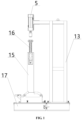
FIG. 2 is a front view schematic diagram of a trailer type pneumatic vibrating device of the automatic cloth-vibrating and cake-removing trailer in the present disclosure. -
FIG. 3 is a side view schematic diagram of the trailer type pneumatic vibrating device of the automatic cloth-vibrating and cake-removing trailer in the present disclosure. -
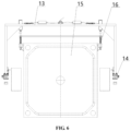
FIG. 4 is a top view schematic diagram of the trailer type pneumatic vibrating device of the automatic cloth-vibrating and cake-removing trailer in the present disclosure. -
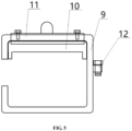
FIG. 5 is a schematic diagram of a movable trailer seat of the automatic cloth-vibrating and cake-removing trailer in the present disclosure. -
FIG. 6 is an assembled schematic diagram (including components closely related to the automatic cloth-vibrating and cake-removing trailer) of the automatic cloth-vibrating and cake-removing trailer in the present disclosure. -
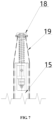
FIG. 7 is a schematic diagram (including components closely related to an elastic cloth-vibrating device) of the elastic cloth-vibrating device of the automatic cloth-vibrating and cake-removing trailer in the present disclosure. -
FIG. 8 is a finally assembled schematic diagram of the automatic cloth-vibrating and cake-removing trailer and an automatic cloth-vibrating and cloth-washing compatible filter press in the present disclosure. - Reference signs in drawings: 1, trailer type pneumatic vibrating device (namely automatic cloth-vibrating and cake-removing trailer main body); 2, movable trailer seat; 3, gate-type trailer frame; 4, cantilever type air cylinder platform; 5, vibrating air cylinder; 6, air storage tank; 7, electromagnetic valve; 8, three-way joint; 9, trailer seat main body; 10, wear-resistant block; 11, pull-plate induction plate; 12, trailer pin assembly;13, automatic cloth-vibrating and cake-removing trailer (the present disclosure); 14, pull-plate trolley slide way; 15, filter plate; 16, elastic cloth-vibrating device (namely automatic cloth-vibrating and cake-removing trailer split body); 17, pull-plate trolley; 18, cloth hanging rod assembly; 19, filter cloth; 20, automatic cloth washing mechanism (namely lifting type cloth washing mechanism); 21, machine tailstock; 22, thrust plate; and 23, PLC program control system (namely PLC program control cabinet).
- The following clearly and completely describes the technical scheme in the embodiments of the present disclosure with reference to the attached figures in the embodiments of an automatic cloth-vibrating and cake-removing trailer and a corresponding automatic cloth-vibrating and cloth-washing compatible filter press in the present disclosure. Apparently, the described embodiments are merely a part rather than all of the embodiments of the present disclosure. All other embodiments, such as the automatic cloth-vibrating and cake-removing trailer with same cloth-vibrating and cake-removing compatible principle and similar structure, obtained by those skilled in the art based on the embodiments of the present disclosure without creative efforts shall fall within the protection scope of the present disclosure.
- The key points of innovative total embodiments of automatic cloth-vibrating and cake-removing trailer 13 (cloth-vibrating and cake-removing trailer for short) are as follows: a vehicle-mounted pneumatic vibrating device is improved into a trailer type pneumatic vibrating
device 1 on the basis of an existing pull-plate cake discharging mechanism: (1)movable trailer seats 2 are creatively additionally arranged, so that the trailer typepneumatic vibrating device 1 can be hung on two pull-plate trolleys 17 to work; if necessary, thepneumatic vibrating device 1 can also be unhooked (separated from the two pull-plate trolleys 17) and stopped at the edge of amachine tailstock 21, normal work of the automatic filtercloth cleaning mechanism 20 is not hindered, and compatibility of automatic cloth vibration and cloth cleaning of the filter press is achieved; and (2) the cantilever typeair cylinder platforms 4 are adaptively added, so that the vibratingair cylinders 5 are aligned with and vibrate elastic cloth-vibratingdevices 16, and the elastic cloth-vibratingdevices 16 are automatically reset by reset springs, so that residual sticky cakes on thefilter cloth 19 are vibrated and shaken, and automatic cake removal is realized. - Through specific embodiments, the cloth-vibrating and cake-removing
trailer 13 mainly consists of the trailer type pneumatic vibratingdevice 1 and the elastic cloth-vibratingdevices 16; (1) the trailer typepneumatic vibrating device 1 comprisesmovable trailer seats 1, a gate-type trailer frame 3, cantilever typeair cylinder platforms 4, vibratingair cylinders 5,air storage tanks 6,electromagnetic valves 7 and a three-way joint 8; (2) each elastic cloth-vibratingdevice 16 comprises a cloth vibrating seat, a telescopic column, a cloth hanging rod assembly and a reset spring; the trailer typepneumatic vibrating device 1 is placed on two pull-platetrolley slide ways 14, is hung on the two pull-plate trolleys 17 through thetrailer pin assemblies 12 and can synchronously move along with the two pull-plate trolleys 17; when necessary, thepneumatic vibrating device 1 can also be unhooked and stopped at the edge of amachine tailstock 21; and the trailer type pneumatic vibrating device has the functions of automatic cloth vibration, automatic cake removal and unhooking. The detailed description is as follows: - Each
movable trailer seat 2 comprises a trailer seatmain body 9, a wear-resistant block 10, a pull-plate induction plate 11 and atrailer pin assembly 12, themovable trailer seats 2 sleeve the pull-platetrolley slide ways 14, and themovable trailer seats 2 are used for bearing the weight of and guiding the cloth-vibrating and cake-removingtrailer 13 and hooking the pull-plate trolleys 17. - The trailer seat
main bodies 9 are double-square-shaped trailer sleeve seats with left openings, the inner diameters of the trailer seatmain bodies 9 are matched with the square pull-platetrolley slide ways 14, and the lengths of the trailer seatmain bodies 9 are greater than the width (thickness) of the gate-type trailer frame 4; and the trailer seatmain bodies 9 are used for mounting the assemblies of themovable trailer seats 2 and bearing the weight of the gate-type trailer frame 3. - The wear-
resistant blocks 10 are groove-shaped wear-resistant blocks, groove openings of the wear-resistant blocks 10 are in clearance fit with the pull-platetrolley slide ways 14, the lengths of the wear-resistant blocks 10 correspond to the inner diameters of the trailer seatmain bodies 9, and the wear-resistant blocks 10 are formed by polypropylene injection molding; and the wear-resistant blocks 10 are mounted at the upper parts in the trailer seatmain bodies 9 and used as sliding parts of the cloth-vibrating and cake-removingtrailer 13. - The pull-
plate induction plates 11 are angle steel type induction plates, double mounting holes are formed in the upper edge of each pull-plate induction plate, and the widths of the front edges are larger than the wall thicknesses of thetrailer seat bodies 9; and the pull-plate induction plates 11 are mounted on the trailer seatmain bodies 9, and the pull-plate induction plates 11 are used for blocking the wear-resistant blocks 10 from sliding outwards and used as induction points of a pull-plate travel inductor. - Each
trailer pin assembly 12 comprises trailer connecting lugs and a trailer connecting pin, the trailer connecting lugs are a pair of connecting lugs, and connecting pin inserting holes are formed in the trailer connecting lugs; and two trailer connecting lugs are welded to the sides of themovable trailer seats 2 and the pull-plate trolleys 17 in a matched mode, and trailer connecting pins are inserted into the connecting pin inserting holes of the two trailer connecting lugs; and thetrailer pin assemblies 12 are used for hooking the pull-plate trolleys 17. - The gate-
type trailer frame 3 is a double-layer gate-type frame, a connecting plate is arranged between the two layers, triangular stabilizing plates are arranged at the left upper corner and the right upper corner, the width of the gate-type trailer frame 3 corresponds to the distance between the two pull-platetrolley slide ways 14, the height of the gate-type trailer frame 3 adapts to the vibratingair cylinders 5 to vibrate the elastic cloth-vibratingdevices 16, and a stainless steel square tube material is adopted; the gate-type trailer frame 3 is vertically welded on themovable trailer seats 2; and the gate-type trailer frame 3 is used for mounting pneumatic elements of thepneumatic vibrating device 1 at high positions. - Vibrating air cylinder mounting holes are formed in the cantilever type
air cylinder platforms 4, the arm lengths of the cantilever typeair cylinder platforms 4 adapt to the vibratingair cylinders 5 and can be aligned with the elastic cloth-vibratingdevices 16, and the stainless steel square tube material is adopted; the cantilever typeair cylinder platforms 4 are horizontally welded on the gate-type trailer frame 3; and the cantilever typeair cylinder platforms 4 are used for mounting the vibratingair cylinders 5 in a cantilever mode, so that the vibratingair cylinders 5 are aligned with the elastic cloth-vibratingdevices 16. - The vibrating
air cylinders 5 are SC40*100S type air cylinders; theair storage tanks 6 are of closed barrel body structures, quick coupling mounting holes are formed in the two ends of eachair storage tank 6; by using vibrating air cylinder seats, the vibratingair cylinders 5 are aligned with the elastic cloth-vibratingdevices 16, and are vertically mounted on the cantilever typeair cylinder platforms 4; and the vibratingair cylinders 5 are used for providing power for vibratingfilter cloth 19. - The
air storage tanks 6 are of closed barrel body structures, quick coupling mounting holes are formed in the two ends of eachair storage tank 6, and the stainless steel material is adopted; theair storage tanks 6 are mounted between theelectromagnetic valves 7 and the three-way joint 8; and theair storage tanks 6 are used for storing and supplying stable high-pressure gas at a short distance. - The
electromagnetic valves 7 are 4v210-08 type electromagnetic valves; and theelectromagnetic valves 7 are mounted between the vibratingair cylinders 5 and theair storage tanks 6, are externally connected with a PLCprogram control cabinet 23 and are used for controlling the vibratingair cylinders 5 to work by switching high-pressure airflow pipelines, and the vibrating frequency is adjustable. - The three-
way joint 8 is centrally mounted on the gate-type trailer frame 3, and is externally connected with a high-pressure gas input hose; and the three-way joint 8 is used for shunting high-pressure gas. - The elastic cloth-vibrating
devices 16 are mounted at the upper ends on two sides of filter plates, are used for hanging thefilter cloth 19 in a penetrating mode, and are matched with the trailer typepneumatic vibrating device 1 to automatically vibrate and shake thefilter cloth 19, so that automatic cake removal is realized. - Telescopic column gap mounting deep holes are formed in the cloth vibrating seats, and the two cloth vibrating seats are mounted at the upper ends of the two sides of each
filter plate 15 and used for mounting the telescopic columns and the reset springs. - Cloth hanging rod assembly mounting holes are formed in the telescopic columns, the outer diameters of the telescopic columns correspond to the hole diameters of the cloth vibrating seats, and the telescopic columns are mounted in the gap mounting deep holes of the cloth vibrating seats and used for elastically supporting the cloth
hanging rod assemblies 18. - Each cloth
hanging rod assembly 18 comprises a filter cloth penetrating and hanging rod, a cloth pulling rod and a cloth hanging rod sleeve; and the clothhanging rod assemblies 18 are used for penetrating and hanging thefilter cloth 10 on double faces of thefilter plates 15 and tensioning thefilter cloth 19 by gravity. - The filter cloth penetrating and hanging rods and the cloth pulling rods are stainless steel tubes, the lengths of the filter cloth penetrating and hanging rods and the cloth pulling rods are larger than the width of
filter cloth 19, thefilter cloth 19 is hung on the filter cloth penetrating and hanging rods in the penetrating mode, the filter cloth penetrating and hanging rods are mounted in the double cloth hanging rod sleeves, and the cloth pulling rods penetrate through the lower end of thefilter cloth 19; and the filter cloth penetrating and hanging rods and the cloth pulling rods are used for penetrating and hanging thefilter cloth 19 and tensioning thefilter cloth 19 by gravity. - Double sleeve holes are formed in the double hanging rod sleeves, the hole diameters of the double hanging rod sleeves correspond to the outer diameters of the filter cloth penetrating and hanging rods, and the cloth hanging rod sleeves are mounted at the upper ends of the telescopic columns and are used for mounting the double filter cloth penetrating and hanging rods.
- The inner diameters of the reset springs correspond to the outer diameters of the telescopic columns, the lengths of the springs correspond to the design expansion and contraction quantity of the telescopic columns, and the reset springs sleeve the telescopic columns and are used for elastically tensioning the
filter cloth 19 and resetting the elastic cloth-vibratingdevices 16. - The automatic cloth-vibrating and cake-removing
trailer 13 provided by the present disclosure has the advantages that the structure is optimized, cloth vibration and cloth washing are compatible, multiple functions are achieved, and unhooking is convenient; the technical problems that a main body of an automatic cloth-vibrating and cake-removing device is fixedly mounted on the two pull-plate trolleys 17, normal work of the automatic filtercloth cleaning mechanism 20 is hindered, an automatic cake-removing filter press loses an automatic cloth cleaning function, and cloth vibration and cloth cleaning are incompatible are solved; and the automation level and the production efficiency of the filter press are improved. - An automatic cloth-vibrating and cloth-washing compatible filter press is an automatic filter press compatible with cloth vibration and cloth washing, and the automatic cloth-vibrating and cake-removing
trailer 13 provided by the present disclosure is used for the filter press; the filter press mainly consists of a double-beam rack, a filter plate pressing mechanism, a multi-filter-chamber filtering mechanism, a pull-plate cake discharging mechanism, a cloth-vibrating and cake-removingtrailer 13 of the pull-plate cake discharging mechanism, a lifting typecloth washing mechanism 20, a liquid receiving plate overturning mechanism and a PLCprogram control system 23; and the filter press is applicable for solid-liquid separation of various viscous suspension solutions. Common technical parts of the present disclosure in the prior art are manufactured according to the current standard JB/T4333 of the mechanical industry of China, namely "part one: type and basic parameters in compartment type filter press and plate-and-frame filter press", "part two: technical conditions", "part three: filter plate" and "part four: diaphragm filter plate". - The pull-plate cake discharging mechanism, namely a cloth-vibrating and cake-removing mechanism capable of automatically pulling open the filter plates, mainly consists of a pull-plate driving motor, pull-
plate trolleys 17, guide rails of the pull-plate trolleys 17, a chain transmission device, the automatic cloth-vibrating and cake-removing trailer 13 (comprising the trailer type pneumatic vibratingdevice 1 and the elastic cloth-vibrating devices 16) and a sensor; and the pull-plate cake discharging mechanism has the functions that thefilter plates 15 can be automatically pulled open and automatic cloth vibration to assist cake removal and unhooking are achieved. - Assembly and final assembly of the pull-plate cake discharging mechanism are as follows: (1) the driving motor is mounted on a machine head or a machine tail (preferably mounted on the machine head), the pull-
plate trolleys 17 are mounted ontrolley slide ways 14 on two sides of double main beams, and a two-stage transmission chain is connected with a driving device and the pull-plate trolleys 17; (2) the trailer type pneumatic vibratingdevice 1 is arranged on the double pull-platetrolley slide ways 14 at the end of themachine tailstock 21, and is hung on the two pull-plate trolleys 17 through thetrailer pin assemblies 12; and the elastic cloth-vibratingdevices 16 are mounted at the upper ends of two sides of thefilter plates 15, the vibratingair cylinders 5 are aligned with the elastic cloth-vibratingdevices 16, and the sensor communicates with thePLC control system 23. - The working process of the pull-plate cake discharging mechanism is as follows: (1) under the control of the
PLC system 23, the driving motor drives pull-plate trolleys 17 on the two sides to synchronously move back and forth through the two-stage transmission chain, the automatic cloth-vibrating and cake-removingtrailer 13 synchronously moves along with the pull-plate trolleys 17, manipulators of the pull-plate trolleys 17 automatically pulls open thefilter plates 15 one by one to discharge cakes, and the automatic cloth-vibrating and cake-removingtrailer 13 generates vibration force to assist gravity to realize thorough cake removal; and (2) when necessary, the pneumatic vibratingdevice 1 can also be unhooked (separated from the two pull-plate trolleys 17) and stopped at the edge of themachine tailstock 21, normal work of the automatic filtercloth cleaning mechanism 20 is not hindered, and the compatibility of automatic cloth vibration and cloth cleaning of the filter press is realized. - The lifting type
cloth washing mechanism 20, namely an automatic lifting type filter cloth washing mechanism, is an on-line automatic washing device forfilter cloth 19 wrapped on thefilter plates 15 by utilizing high-pressure water irregularly (when necessary), and is positioned at the upper part of the filter press; the lifting typecloth washing mechanism 20 mainly consists of a lifting cloth washing trolley, a trolley guide rail support, a trolley limiting device and the like; the lifting type cloth washing trolley comprises a movable trolley frame, a lifting pipeline, a washing transverse pipe and a driving motor; the lifting type cloth washing trolley is mounted on the trolley guide rail support on the two sides of the double main beams beside a machine head thrust plate; and the lifting typecloth washing mechanism 20 has the functions of automatically cleaning the filter cloth and washing and regenerating the filter cloth. - The working process of the lifting type
cloth washing mechanism 20 is as follows: (1) after the filter press automatically removes cakes, the automatic cloth-vibrating and cake-removingtrailer 13 and the two pull-plate trolleys 17 are unhooked and stopped at the edge of themachine tailstock 21 when necessary, and under the control of thePLC control system 23, the pull-plate trolleys 17 automatically pull open thefilter plates 15 to a cleaning position one by one (the limiting device acts); and (2) the lifting typecloth washing mechanism 20 and the pull-plate trolleys 17 synchronously operate and automatically lift, and thefilter cloth 19 is automatically washed and smoothed by high-pressure water through the lifting pipeline and the washing transverse pipe, so that the filtration speed of thefilter cloth 19 is increased, and the service life of thefilter cloth 19 is prolonged. - The filter press has multiple functions of automatically pulling open the
filter plates 15, automatically vibrating cloth to assist cake removal and automatically cleaning thefilter cloth 19; the single complete operation cycle of the filter press comprises the following steps: pressing thefilter plates 15, performing feeding and filtration, performing plate overturning and liquid receiving, performing washing purification, back-blowing materials, performing blow-drying purification, pulling the plates to discharge cakes, vibrating cloth to remove cakes, and cleaning thefilter cloth 19, and is automatically completed by one key under the control of the PLCprogram control system 23; and batch solid-liquid separation is realized through intermittent reciprocating cycle work. - The automatic cloth-vibrating and cloth-washing compatible filter press provided by the present disclosure has the beneficial effects that the vehicle-mounted pneumatic vibrating device is improved into the trailer type pneumatic vibrating
device 1, so that the trailer type pneumatic vibratingdevice 1 can be hung on the two pull-plate trolleys 17 to work, the pneumatic vibratingdevice 1 can also be unhooked and stopped at the edge of themachine tailstock 21 when necessary, normal work of the automatic filtercloth cleaning mechanism 20 is not hindered, and compatibility of automatic cloth vibration and cloth cleaning of the filter press is realized; the technical problem that people always want to solve but cannot obtain successful compatibility of cloth vibration and cloth washing is solved; and the automation level and the production efficiency of the filter press are improved, and the energy is expanded and the efficiency is increased.
Claims (4)
- An automatic cloth-vibrating and cake-removing trailer, comprising:- a trailer type pneumatic vibrating device (1) and- elastic cloth-vibrating devices (16),A) wherein the trailer type pneumatic vibrating device (1) comprises:- movable trailer seats (2),- a gate-type trailer frame (3) welded on the movable trailer seats (2) and which extends in a vertical direction,- cantilever type air cylinder platforms (4) welded on and perpendicular to said gate-type trailer frame (3) and which extend in a horizontal direction,- two vibrating air cylinders (5) aligned with said elastic cloth-vibrating devices (16), wherein one of the two vibrating air cylinders (5) is vertically mounted on each of said cantilever type air cylinder platforms (4),- two air storage tanks (6),- two electromagnetic valves (7) and- a three-way joint (8) centrally mounted on the gate-type trailer frame (3) and which is externally connected with a high-pressure gas input hose; wherein each of the two electromagnetic valves (7) and each of the two gas storage tanks (6) are sequentially mounted between respectively one of the two vibrating air cylinders (5) and the three-way joint (8), wherein one of the two vibrating air cylinders (5) and an end of one of the two electromagnetic valves (7) are connected through an air conveying hose, an other end of the one of the electromagnetic valves (7) and an end of one of the two air storage tanks (6) are connected through an air conveying hose, an other end of the one of the two air storage tanks (6) and an end of the three-way joint (8) are connected through an air conveying hose, an other end of the three-way joint (8) and an end of the other one of the two air storage tanks (6) are connected through an air conveying hose, an other end of the other one of the two second air storage tanks (6) and an end of the other one of the two electromagnetic valves (7) are connected through an air conveying hose, an other end of the other one of the two electromagnetic valves (7) and the other one of the two vibrating air cylinders (5) are connected through an air conveying hose, and wherein the two electromagnetic valves (7) are externally connected with a PLC program control cabinet (23);wherein each movable trailer seat (2) comprises:- a trailer seat main body (9), wherein said trailer seat main body (9) is a C-shaped trailer seat with an opening facing towards a filter plate (15),- a wear-resistant block (10), wherein the wear resistant block (10) is mounted at an upper part in the trailer seat main body (9),- a pull-plate induction plate (11), wherein said pull-plate induction plate (11) is an angle steel plate, wherein two holes are formed in an upper edge of said pull-plate induction plate (11), and wherein a width of a front edge of the pull-plate induction plate (11) is larger than a wall thickness of the trailer seat main body (9) such that the pull-plate induction plate (11) blocks the wear-resistant block (10) from sliding outward; and- a trailer pin assembly (12), wherein the trailer pin assembly (12) comprises two trailer connecting lugs and a trailer connecting pin, wherein a connecting pin inserting hole is formed in each of the two trailer connecting lugs, wherein each of the two trailer connecting lugs is welded to either side of a corresponding one of the movable trailer seats (2) and either side of a corresponding one of the two pull-plate trolleys (17) in a matched mode, and the trailer connecting pin is inserted into the connecting pin inserting holes of the two trailer connecting lugs;B) wherein each elastic cloth-vibrating device (16) comprises:- a cloth vibrating seat,- a telescopic column mounted in the cloth vibrating seat,- a cloth hanging rod assembly (18), and- a reset spring which sleeves said telescopic column;wherein the cloth hanging rod assembly (18) comprises:- a filter cloth penetrating and hanging rod,- a cloth pulling rod and- a cloth hanging rod sleeve, wherein the cloth hanging rod sleeve is mounted on said telescopic column;wherein the cloth vibrating seat is mounted on each side of an upper end of the filter plate (15) on which a filter cloth (19) is wrapped;wherein the filter cloth (19) is hung on the filter cloth penetrating and hanging rod, wherein the filter cloth penetrating and hanging rod is mounted in the cloth hanging rod sleeve, and the cloth pulling rod is mounted at a lower end of the filter cloth (19) in a penetrating mode;C) the trailer type pneumatic vibrating device (1) is hung on the two pull-plate trolleys (17) through the trailer pin assembly (12) and can synchronously move along with the two pull-plate trolleys (17);when necessary, the pneumatic vibrating device (1) can also be unhooked and stopped at an edge of a machine tailstock (21); andthe trailer type pneumatic vibrating device has functions of automatic cloth vibration to assist cake removal and unhooking.
- The automatic cloth-vibrating and cake-removing trailer according to claim 1, wherein an inner diameter of each trailer seat main body (9) is matched with each of the pull-plate trolley slide ways, and a length of each trailer seat main body (9) is greater than a width (thickness) of the gate-type trailer frame (3);
wherein each wear-resistant block (10) is a groove-shaped wear-resistant block (10), a groove opening of each wear-resistant block (10) is in clearance fit with a corresponding pull-plate trolley (17) slide way, a length of each wear-resistant block (10) corresponds to the inner diameter of the trailer seat main body (9), and each wear-resistant block (10) is formed by polypropylene injection molding. - The automatic cloth-vibrating and cake-removing trailer according to claim 1, wherein the gate-type trailer frame (3) is a double-layer gate-type frame, a connecting plate is arranged between two layers of the double-layer gate-type frame, triangular stabilizing plates are arranged at a left upper corner and a right upper corner, a width of the gate-type trailer frame (3) corresponds to a distance between the two pull-plate trolley (17) slide ways, a height of the gate-type trailer frame (3) adapts to the vibrating air cylinders (5) to vibrate the elastic cloth-vibrating devices (16), and a stainless steel square tube material is adopted; and
wherein vibrating air cylinder mounting holes are formed in the cantilever type air cylinder platforms (4), arm lengths of the cantilever type air cylinder platforms (4) adapt to the vibrating air cylinders (5) and can be aligned with the elastic cloth-vibrating devices (16), and the stainless steel square tube material is adopted. - An automatic cloth-vibrating and cloth-washing compatible filter press, being an automatic filter press compatible with cloth vibration and cloth washing, comprising- a double-beam rack,- a filter plate pressing mechanism,- a multi-filter-chamber filtering mechanism,- a pull-plate cake discharging mechanism,- a cloth-vibrating and cake-removing trailer of the pull-plate cake discharging mechanism,- a lifting type cloth washing mechanism (20),- a liquid receiving plate overturning mechanism and- a PLC program control system (23),wherein the cloth-vibrating and cake-removing trailer is the automatic cloth-vibrating and cake-removing trailer according to claims 1 to 3; andwherein the cloth-vibrating and cake-removing trailer has multiple functions of automatically pulling open the filter plates, automatically vibrating cloth to assist cake removal and automatically cleaning the filter cloth.
Applications Claiming Priority (1)
| Application Number | Priority Date | Filing Date | Title |
|---|---|---|---|
| CN202110402881.XA CN112892012B (en) | 2021-04-15 | 2021-04-15 | Automatic cloth-vibrating cake-removing trailer and corresponding automatic cloth-vibrating and cloth-washing compatible filter press |
Publications (2)
| Publication Number | Publication Date |
|---|---|
| EP4074396A1 EP4074396A1 (en) | 2022-10-19 |
| EP4074396B1 true EP4074396B1 (en) | 2025-07-09 |
Family
ID=76110534
Family Applications (1)
| Application Number | Title | Priority Date | Filing Date |
|---|---|---|---|
| EP21190324.0A Active EP4074396B1 (en) | 2021-04-15 | 2021-08-09 | Automatic cloth-vibrating and cake-removing trailer and corresponding automatic cloth-vibrating and cloth-washing compatible filter press |
Country Status (2)
| Country | Link |
|---|---|
| EP (1) | EP4074396B1 (en) |
| CN (1) | CN112892012B (en) |
Families Citing this family (3)
| Publication number | Priority date | Publication date | Assignee | Title |
|---|---|---|---|---|
| CN112892012B (en) * | 2021-04-15 | 2024-07-23 | 景津装备股份有限公司 | Automatic cloth-vibrating cake-removing trailer and corresponding automatic cloth-vibrating and cloth-washing compatible filter press |
| CN113384926B (en) * | 2021-07-20 | 2024-07-23 | 景津装备股份有限公司 | Automatic disengaging device of automatic cloth vibrating trailer |
| CN117225041B (en) * | 2023-08-24 | 2025-11-14 | 安徽万磁电子股份有限公司 | A wastewater treatment process for ball mill workshops |
Family Cites Families (12)
| Publication number | Priority date | Publication date | Assignee | Title |
|---|---|---|---|---|
| US4209404A (en) * | 1975-05-22 | 1980-06-24 | Ngk Insulators, Ltd. | Filter press |
| DE3007404A1 (en) * | 1979-04-05 | 1980-10-23 | Ishigaki Mech Ind | DEVICE FOR REMOVING THE FILTER CAKE FROM A FILTER PRESS |
| JP3495811B2 (en) * | 1995-02-28 | 2004-02-09 | 株式会社栗田機械製作所 | Filter press filter hanging device |
| CN2796796Y (en) * | 2005-04-16 | 2006-07-19 | 王兆群 | Cloth washing device on filter press |
| CN100591402C (en) * | 2006-08-01 | 2010-02-24 | 杭州兴源过滤科技股份有限公司 | Vibration Mechanism and Vibration Method of Filter Cloth Variation in Filter Press |
| CN101485942B (en) * | 2009-01-10 | 2011-10-19 | 杭州兴源过滤科技股份有限公司 | Gas-liquid telescoping, rapping and water flushing device for filter press and telescoping, rapping and water flushing method |
| CN101601942B (en) * | 2009-07-07 | 2011-04-13 | 景津压滤机集团有限公司 | Split shaking device of filter press filter board |
| CN207822588U (en) * | 2018-01-04 | 2018-09-07 | 景津环保股份有限公司 | A kind of pneumatic vibrator cake discharge filter press |
| CN112044129A (en) * | 2020-09-15 | 2020-12-08 | 景津环保股份有限公司 | Automatic cloth-vibrating cake-removing device and corresponding automatic cake-removing filter press |
| CN212818345U (en) * | 2020-10-20 | 2021-03-30 | 中大贝莱特压滤机有限公司 | Filter cloth supporting mechanism and cake unloading mechanism |
| CN112892012B (en) * | 2021-04-15 | 2024-07-23 | 景津装备股份有限公司 | Automatic cloth-vibrating cake-removing trailer and corresponding automatic cloth-vibrating and cloth-washing compatible filter press |
| CN214763540U (en) * | 2021-04-15 | 2021-11-19 | 景津环保股份有限公司 | Automatic cloth-vibrating cake-removing trailer and corresponding automatic cloth-vibrating and cloth-washing compatible filter press |
-
2021
- 2021-04-15 CN CN202110402881.XA patent/CN112892012B/en active Active
- 2021-08-09 EP EP21190324.0A patent/EP4074396B1/en active Active
Also Published As
| Publication number | Publication date |
|---|---|
| CN112892012A (en) | 2021-06-04 |
| CN112892012B (en) | 2024-07-23 |
| EP4074396A1 (en) | 2022-10-19 |
Similar Documents
| Publication | Publication Date | Title |
|---|---|---|
| EP4074396A1 (en) | Automatic cloth-vibrating and cake-removing trailer and corresponding automatic cloth-vibrating and cloth-washing compatible filter press | |
| CN101293152B (en) | Horizontal pressure filter | |
| EP2452736B1 (en) | Grouping vibration device for filter plates of press filter | |
| EP2692403B1 (en) | Scraper device for discharging filter cake on filter plate of pressure filter | |
| EP0332896B1 (en) | Apparatus for pressure molding ceramic articles | |
| CN102389659B (en) | Quick filter cake removing and filter cloth washing device for filter press | |
| CN201482269U (en) | Horizontal press filter | |
| CN109879072B (en) | Tobacco shred box overturning and dumping machine | |
| CN214763540U (en) | Automatic cloth-vibrating cake-removing trailer and corresponding automatic cloth-vibrating and cloth-washing compatible filter press | |
| JPH0133128Y2 (en) | ||
| EP4466081A1 (en) | Improved filter press | |
| CN214232929U (en) | Plate and frame filter press | |
| CN202270397U (en) | Device for quickly discharging cakes and cleaning filter cloth of pressure filter | |
| CN213134298U (en) | Cleaning machine | |
| CN112044129A (en) | Automatic cloth-vibrating cake-removing device and corresponding automatic cake-removing filter press | |
| CN112495013A (en) | Automatic scraping device for filter cake of filter press | |
| CN119971571A (en) | Automatic filter press using grouped pull plates to assist in mud unloading and mud unloading control method | |
| CN210448217U (en) | Automatic hanging plate device for filter cloth installation of filter plate | |
| CN110090840B (en) | Vinegar jar cleaning machine set | |
| CN2675222Y (en) | Automatic mud scraping and filter cloth cleaning device of full automatic filter press | |
| CN214634306U (en) | Automatic device for cleaning feed inlet | |
| CN217661709U (en) | Self-uniform plate quick-connection pipe type lifting horizontal water spray pipe device of grouped filter cloth cleaning mechanism | |
| CN212818345U (en) | Filter cloth supporting mechanism and cake unloading mechanism | |
| CN212119145U (en) | Gas storage device of pneumatic vibrating plate and corresponding vibrating type plate pulling trolley | |
| CN110917683A (en) | One-time pulling-open filter plate vibration cake-unloading filter press |
Legal Events
| Date | Code | Title | Description |
|---|---|---|---|
| PUAI | Public reference made under article 153(3) epc to a published international application that has entered the european phase |
Free format text: ORIGINAL CODE: 0009012 |
|
| STAA | Information on the status of an ep patent application or granted ep patent |
Free format text: STATUS: REQUEST FOR EXAMINATION WAS MADE |
|
| 17P | Request for examination filed |
Effective date: 20210809 |
|
| AK | Designated contracting states |
Kind code of ref document: A1 Designated state(s): AL AT BE BG CH CY CZ DE DK EE ES FI FR GB GR HR HU IE IS IT LI LT LU LV MC MK MT NL NO PL PT RO RS SE SI SK SM TR |
|
| P01 | Opt-out of the competence of the unified patent court (upc) registered |
Effective date: 20230526 |
|
| STAA | Information on the status of an ep patent application or granted ep patent |
Free format text: STATUS: EXAMINATION IS IN PROGRESS |
|
| 17Q | First examination report despatched |
Effective date: 20230907 |
|
| GRAP | Despatch of communication of intention to grant a patent |
Free format text: ORIGINAL CODE: EPIDOSNIGR1 |
|
| STAA | Information on the status of an ep patent application or granted ep patent |
Free format text: STATUS: GRANT OF PATENT IS INTENDED |
|
| INTG | Intention to grant announced |
Effective date: 20250327 |
|
| GRAS | Grant fee paid |
Free format text: ORIGINAL CODE: EPIDOSNIGR3 |
|
| GRAA | (expected) grant |
Free format text: ORIGINAL CODE: 0009210 |
|
| STAA | Information on the status of an ep patent application or granted ep patent |
Free format text: STATUS: THE PATENT HAS BEEN GRANTED |
|
| AK | Designated contracting states |
Kind code of ref document: B1 Designated state(s): AL AT BE BG CH CY CZ DE DK EE ES FI FR GB GR HR HU IE IS IT LI LT LU LV MC MK MT NL NO PL PT RO RS SE SI SK SM TR |
|
| REG | Reference to a national code |
Ref country code: GB Ref legal event code: FG4D |
|
| REG | Reference to a national code |
Ref country code: CH Ref legal event code: EP |
|
| REG | Reference to a national code |
Ref country code: IE Ref legal event code: FG4D |
|
| REG | Reference to a national code |
Ref country code: DE Ref legal event code: R096 Ref document number: 602021033662 Country of ref document: DE |
|
| PGFP | Annual fee paid to national office [announced via postgrant information from national office to epo] |
Ref country code: DE Payment date: 20250903 Year of fee payment: 5 |
|
| PGFP | Annual fee paid to national office [announced via postgrant information from national office to epo] |
Ref country code: AT Payment date: 20251020 Year of fee payment: 5 Ref country code: FR Payment date: 20250904 Year of fee payment: 5 |
|
| REG | Reference to a national code |
Ref country code: NL Ref legal event code: MP Effective date: 20250709 |
|
| PG25 | Lapsed in a contracting state [announced via postgrant information from national office to epo] |
Ref country code: PT Free format text: LAPSE BECAUSE OF FAILURE TO SUBMIT A TRANSLATION OF THE DESCRIPTION OR TO PAY THE FEE WITHIN THE PRESCRIBED TIME-LIMIT Effective date: 20251110 |
|
| PG25 | Lapsed in a contracting state [announced via postgrant information from national office to epo] |
Ref country code: NL Free format text: LAPSE BECAUSE OF FAILURE TO SUBMIT A TRANSLATION OF THE DESCRIPTION OR TO PAY THE FEE WITHIN THE PRESCRIBED TIME-LIMIT Effective date: 20250709 |
|
| REG | Reference to a national code |
Ref country code: AT Ref legal event code: MK05 Ref document number: 1811348 Country of ref document: AT Kind code of ref document: T Effective date: 20250709 |
|
| PG25 | Lapsed in a contracting state [announced via postgrant information from national office to epo] |
Ref country code: IS Free format text: LAPSE BECAUSE OF FAILURE TO SUBMIT A TRANSLATION OF THE DESCRIPTION OR TO PAY THE FEE WITHIN THE PRESCRIBED TIME-LIMIT Effective date: 20251109 |
|
| PG25 | Lapsed in a contracting state [announced via postgrant information from national office to epo] |
Ref country code: NO Free format text: LAPSE BECAUSE OF FAILURE TO SUBMIT A TRANSLATION OF THE DESCRIPTION OR TO PAY THE FEE WITHIN THE PRESCRIBED TIME-LIMIT Effective date: 20251009 |
|
| REG | Reference to a national code |
Ref country code: LT Ref legal event code: MG9D |
|
| PG25 | Lapsed in a contracting state [announced via postgrant information from national office to epo] |
Ref country code: AT Free format text: LAPSE BECAUSE OF FAILURE TO SUBMIT A TRANSLATION OF THE DESCRIPTION OR TO PAY THE FEE WITHIN THE PRESCRIBED TIME-LIMIT Effective date: 20250709 |
|
| PG25 | Lapsed in a contracting state [announced via postgrant information from national office to epo] |
Ref country code: FI Free format text: LAPSE BECAUSE OF FAILURE TO SUBMIT A TRANSLATION OF THE DESCRIPTION OR TO PAY THE FEE WITHIN THE PRESCRIBED TIME-LIMIT Effective date: 20250709 |
|
| PG25 | Lapsed in a contracting state [announced via postgrant information from national office to epo] |
Ref country code: HR Free format text: LAPSE BECAUSE OF FAILURE TO SUBMIT A TRANSLATION OF THE DESCRIPTION OR TO PAY THE FEE WITHIN THE PRESCRIBED TIME-LIMIT Effective date: 20250709 |
|
| PG25 | Lapsed in a contracting state [announced via postgrant information from national office to epo] |
Ref country code: GR Free format text: LAPSE BECAUSE OF FAILURE TO SUBMIT A TRANSLATION OF THE DESCRIPTION OR TO PAY THE FEE WITHIN THE PRESCRIBED TIME-LIMIT Effective date: 20251010 |
|
| PG25 | Lapsed in a contracting state [announced via postgrant information from national office to epo] |
Ref country code: SE Free format text: LAPSE BECAUSE OF FAILURE TO SUBMIT A TRANSLATION OF THE DESCRIPTION OR TO PAY THE FEE WITHIN THE PRESCRIBED TIME-LIMIT Effective date: 20250709 |
|
| PG25 | Lapsed in a contracting state [announced via postgrant information from national office to epo] |
Ref country code: LV Free format text: LAPSE BECAUSE OF FAILURE TO SUBMIT A TRANSLATION OF THE DESCRIPTION OR TO PAY THE FEE WITHIN THE PRESCRIBED TIME-LIMIT Effective date: 20250709 |
|
| PG25 | Lapsed in a contracting state [announced via postgrant information from national office to epo] |
Ref country code: PL Free format text: LAPSE BECAUSE OF FAILURE TO SUBMIT A TRANSLATION OF THE DESCRIPTION OR TO PAY THE FEE WITHIN THE PRESCRIBED TIME-LIMIT Effective date: 20250709 Ref country code: BG Free format text: LAPSE BECAUSE OF FAILURE TO SUBMIT A TRANSLATION OF THE DESCRIPTION OR TO PAY THE FEE WITHIN THE PRESCRIBED TIME-LIMIT Effective date: 20250709 |
|
| PG25 | Lapsed in a contracting state [announced via postgrant information from national office to epo] |
Ref country code: RS Free format text: LAPSE BECAUSE OF FAILURE TO SUBMIT A TRANSLATION OF THE DESCRIPTION OR TO PAY THE FEE WITHIN THE PRESCRIBED TIME-LIMIT Effective date: 20251009 |
|
| PG25 | Lapsed in a contracting state [announced via postgrant information from national office to epo] |
Ref country code: ES Free format text: LAPSE BECAUSE OF FAILURE TO SUBMIT A TRANSLATION OF THE DESCRIPTION OR TO PAY THE FEE WITHIN THE PRESCRIBED TIME-LIMIT Effective date: 20250709 |
|
| PG25 | Lapsed in a contracting state [announced via postgrant information from national office to epo] |
Ref country code: RO Free format text: LAPSE BECAUSE OF FAILURE TO SUBMIT A TRANSLATION OF THE DESCRIPTION OR TO PAY THE FEE WITHIN THE PRESCRIBED TIME-LIMIT Effective date: 20250709 |
|
| REG | Reference to a national code |
Ref country code: CH Ref legal event code: H13 Free format text: ST27 STATUS EVENT CODE: U-0-0-H10-H13 (AS PROVIDED BY THE NATIONAL OFFICE) Effective date: 20260324 |
|
| PG25 | Lapsed in a contracting state [announced via postgrant information from national office to epo] |
Ref country code: SM Free format text: LAPSE BECAUSE OF FAILURE TO SUBMIT A TRANSLATION OF THE DESCRIPTION OR TO PAY THE FEE WITHIN THE PRESCRIBED TIME-LIMIT Effective date: 20250709 |
|
| PG25 | Lapsed in a contracting state [announced via postgrant information from national office to epo] |
Ref country code: DK Free format text: LAPSE BECAUSE OF FAILURE TO SUBMIT A TRANSLATION OF THE DESCRIPTION OR TO PAY THE FEE WITHIN THE PRESCRIBED TIME-LIMIT Effective date: 20250709 |
|
| PG25 | Lapsed in a contracting state [announced via postgrant information from national office to epo] |
Ref country code: LU Free format text: LAPSE BECAUSE OF NON-PAYMENT OF DUE FEES Effective date: 20250809 Ref country code: IT Free format text: LAPSE BECAUSE OF FAILURE TO SUBMIT A TRANSLATION OF THE DESCRIPTION OR TO PAY THE FEE WITHIN THE PRESCRIBED TIME-LIMIT Effective date: 20250709 |
|
| PG25 | Lapsed in a contracting state [announced via postgrant information from national office to epo] |
Ref country code: CH Free format text: LAPSE BECAUSE OF NON-PAYMENT OF DUE FEES Effective date: 20250831 Ref country code: CZ Free format text: LAPSE BECAUSE OF FAILURE TO SUBMIT A TRANSLATION OF THE DESCRIPTION OR TO PAY THE FEE WITHIN THE PRESCRIBED TIME-LIMIT Effective date: 20250709 |
|
| PG25 | Lapsed in a contracting state [announced via postgrant information from national office to epo] |
Ref country code: SK Free format text: LAPSE BECAUSE OF FAILURE TO SUBMIT A TRANSLATION OF THE DESCRIPTION OR TO PAY THE FEE WITHIN THE PRESCRIBED TIME-LIMIT Effective date: 20250709 Ref country code: EE Free format text: LAPSE BECAUSE OF FAILURE TO SUBMIT A TRANSLATION OF THE DESCRIPTION OR TO PAY THE FEE WITHIN THE PRESCRIBED TIME-LIMIT Effective date: 20250709 |
|
| PLBE | No opposition filed within time limit |
Free format text: ORIGINAL CODE: 0009261 |
|
| STAA | Information on the status of an ep patent application or granted ep patent |
Free format text: STATUS: NO OPPOSITION FILED WITHIN TIME LIMIT |