EP4074254B1 - Beatmungsüberwachung - Google Patents
Beatmungsüberwachung Download PDFInfo
- Publication number
- EP4074254B1 EP4074254B1 EP22177836.8A EP22177836A EP4074254B1 EP 4074254 B1 EP4074254 B1 EP 4074254B1 EP 22177836 A EP22177836 A EP 22177836A EP 4074254 B1 EP4074254 B1 EP 4074254B1
- Authority
- EP
- European Patent Office
- Prior art keywords
- subject
- breath
- endotracheal tube
- ventilation monitoring
- processor
- Prior art date
- Legal status (The legal status is an assumption and is not a legal conclusion. Google has not performed a legal analysis and makes no representation as to the accuracy of the status listed.)
- Active
Links
Images


Classifications
-
- A—HUMAN NECESSITIES
- A61—MEDICAL OR VETERINARY SCIENCE; HYGIENE
- A61B—DIAGNOSIS; SURGERY; IDENTIFICATION
- A61B5/00—Measuring for diagnostic purposes; Identification of persons
- A61B5/08—Measuring devices for evaluating the respiratory organs
- A61B5/083—Measuring rate of metabolism by using breath test, e.g. measuring rate of oxygen consumption
- A61B5/0836—Measuring rate of CO2 production
-
- A—HUMAN NECESSITIES
- A61—MEDICAL OR VETERINARY SCIENCE; HYGIENE
- A61B—DIAGNOSIS; SURGERY; IDENTIFICATION
- A61B5/00—Measuring for diagnostic purposes; Identification of persons
- A61B5/08—Measuring devices for evaluating the respiratory organs
- A61B5/085—Measuring impedance of respiratory organs or lung elasticity
- A61B5/086—Measuring impedance of respiratory organs or lung elasticity by impedance pneumography
-
- A—HUMAN NECESSITIES
- A61—MEDICAL OR VETERINARY SCIENCE; HYGIENE
- A61B—DIAGNOSIS; SURGERY; IDENTIFICATION
- A61B5/00—Measuring for diagnostic purposes; Identification of persons
- A61B5/08—Measuring devices for evaluating the respiratory organs
- A61B5/087—Measuring breath flow
-
- A—HUMAN NECESSITIES
- A61—MEDICAL OR VETERINARY SCIENCE; HYGIENE
- A61B—DIAGNOSIS; SURGERY; IDENTIFICATION
- A61B5/00—Measuring for diagnostic purposes; Identification of persons
- A61B5/24—Detecting, measuring or recording bioelectric or biomagnetic signals of the body or parts thereof
- A61B5/316—Modalities, i.e. specific diagnostic methods
- A61B5/318—Heart-related electrical modalities, e.g. electrocardiography [ECG]
-
- A—HUMAN NECESSITIES
- A61—MEDICAL OR VETERINARY SCIENCE; HYGIENE
- A61B—DIAGNOSIS; SURGERY; IDENTIFICATION
- A61B7/00—Instruments for auscultation
- A61B7/003—Detecting lung or respiration noise
-
- A—HUMAN NECESSITIES
- A61—MEDICAL OR VETERINARY SCIENCE; HYGIENE
- A61M—DEVICES FOR INTRODUCING MEDIA INTO, OR ONTO, THE BODY; DEVICES FOR TRANSDUCING BODY MEDIA OR FOR TAKING MEDIA FROM THE BODY; DEVICES FOR PRODUCING OR ENDING SLEEP OR STUPOR
- A61M16/00—Devices for influencing the respiratory system of patients by gas treatment, e.g. ventilators; Tracheal tubes
- A61M16/0051—Devices for influencing the respiratory system of patients by gas treatment, e.g. ventilators; Tracheal tubes with alarm devices
-
- A—HUMAN NECESSITIES
- A61—MEDICAL OR VETERINARY SCIENCE; HYGIENE
- A61M—DEVICES FOR INTRODUCING MEDIA INTO, OR ONTO, THE BODY; DEVICES FOR TRANSDUCING BODY MEDIA OR FOR TAKING MEDIA FROM THE BODY; DEVICES FOR PRODUCING OR ENDING SLEEP OR STUPOR
- A61M16/00—Devices for influencing the respiratory system of patients by gas treatment, e.g. ventilators; Tracheal tubes
- A61M16/021—Devices for influencing the respiratory system of patients by gas treatment, e.g. ventilators; Tracheal tubes operated by electrical means
-
- A—HUMAN NECESSITIES
- A61—MEDICAL OR VETERINARY SCIENCE; HYGIENE
- A61M—DEVICES FOR INTRODUCING MEDIA INTO, OR ONTO, THE BODY; DEVICES FOR TRANSDUCING BODY MEDIA OR FOR TAKING MEDIA FROM THE BODY; DEVICES FOR PRODUCING OR ENDING SLEEP OR STUPOR
- A61M16/00—Devices for influencing the respiratory system of patients by gas treatment, e.g. ventilators; Tracheal tubes
- A61M16/04—Tracheal tubes
- A61M16/0402—Special features for tracheal tubes not otherwise provided for
- A61M16/0411—Special features for tracheal tubes not otherwise provided for with means for differentiating between oesophageal and tracheal intubation
-
- A—HUMAN NECESSITIES
- A61—MEDICAL OR VETERINARY SCIENCE; HYGIENE
- A61N—ELECTROTHERAPY; MAGNETOTHERAPY; RADIATION THERAPY; ULTRASOUND THERAPY
- A61N1/00—Electrotherapy; Circuits therefor
- A61N1/02—Details
- A61N1/04—Electrodes
- A61N1/0404—Electrodes for external use
- A61N1/0408—Use-related aspects
- A61N1/046—Specially adapted for shock therapy, e.g. defibrillation
-
- A—HUMAN NECESSITIES
- A61—MEDICAL OR VETERINARY SCIENCE; HYGIENE
- A61N—ELECTROTHERAPY; MAGNETOTHERAPY; RADIATION THERAPY; ULTRASOUND THERAPY
- A61N1/00—Electrotherapy; Circuits therefor
- A61N1/18—Applying electric currents by contact electrodes
- A61N1/32—Applying electric currents by contact electrodes alternating or intermittent currents
- A61N1/38—Applying electric currents by contact electrodes alternating or intermittent currents for producing shock effects
- A61N1/39—Heart defibrillators
- A61N1/3925—Monitoring; Protecting
-
- A—HUMAN NECESSITIES
- A61—MEDICAL OR VETERINARY SCIENCE; HYGIENE
- A61M—DEVICES FOR INTRODUCING MEDIA INTO, OR ONTO, THE BODY; DEVICES FOR TRANSDUCING BODY MEDIA OR FOR TAKING MEDIA FROM THE BODY; DEVICES FOR PRODUCING OR ENDING SLEEP OR STUPOR
- A61M16/00—Devices for influencing the respiratory system of patients by gas treatment, e.g. ventilators; Tracheal tubes
- A61M16/0057—Pumps therefor
- A61M16/0084—Pumps therefor self-reinflatable by elasticity, e.g. resuscitation squeeze bags
-
- A—HUMAN NECESSITIES
- A61—MEDICAL OR VETERINARY SCIENCE; HYGIENE
- A61M—DEVICES FOR INTRODUCING MEDIA INTO, OR ONTO, THE BODY; DEVICES FOR TRANSDUCING BODY MEDIA OR FOR TAKING MEDIA FROM THE BODY; DEVICES FOR PRODUCING OR ENDING SLEEP OR STUPOR
- A61M16/00—Devices for influencing the respiratory system of patients by gas treatment, e.g. ventilators; Tracheal tubes
- A61M16/04—Tracheal tubes
-
- A—HUMAN NECESSITIES
- A61—MEDICAL OR VETERINARY SCIENCE; HYGIENE
- A61M—DEVICES FOR INTRODUCING MEDIA INTO, OR ONTO, THE BODY; DEVICES FOR TRANSDUCING BODY MEDIA OR FOR TAKING MEDIA FROM THE BODY; DEVICES FOR PRODUCING OR ENDING SLEEP OR STUPOR
- A61M16/00—Devices for influencing the respiratory system of patients by gas treatment, e.g. ventilators; Tracheal tubes
- A61M16/10—Preparation of respiratory gases or vapours
- A61M16/14—Preparation of respiratory gases or vapours by mixing different fluids, one of them being in a liquid phase
- A61M16/16—Devices to humidify the respiration air
-
- A—HUMAN NECESSITIES
- A61—MEDICAL OR VETERINARY SCIENCE; HYGIENE
- A61M—DEVICES FOR INTRODUCING MEDIA INTO, OR ONTO, THE BODY; DEVICES FOR TRANSDUCING BODY MEDIA OR FOR TAKING MEDIA FROM THE BODY; DEVICES FOR PRODUCING OR ENDING SLEEP OR STUPOR
- A61M16/00—Devices for influencing the respiratory system of patients by gas treatment, e.g. ventilators; Tracheal tubes
- A61M16/04—Tracheal tubes
- A61M16/0402—Special features for tracheal tubes not otherwise provided for
- A61M16/0411—Special features for tracheal tubes not otherwise provided for with means for differentiating between oesophageal and tracheal intubation
- A61M2016/0413—Special features for tracheal tubes not otherwise provided for with means for differentiating between oesophageal and tracheal intubation with detectors of CO2 in exhaled gases
-
- A—HUMAN NECESSITIES
- A61—MEDICAL OR VETERINARY SCIENCE; HYGIENE
- A61M—DEVICES FOR INTRODUCING MEDIA INTO, OR ONTO, THE BODY; DEVICES FOR TRANSDUCING BODY MEDIA OR FOR TAKING MEDIA FROM THE BODY; DEVICES FOR PRODUCING OR ENDING SLEEP OR STUPOR
- A61M16/00—Devices for influencing the respiratory system of patients by gas treatment, e.g. ventilators; Tracheal tubes
- A61M16/10—Preparation of respiratory gases or vapours
- A61M16/1005—Preparation of respiratory gases or vapours with O2 features or with parameter measurement
- A61M2016/102—Measuring a parameter of the content of the delivered gas
- A61M2016/103—Measuring a parameter of the content of the delivered gas the CO2 concentration
-
- A—HUMAN NECESSITIES
- A61—MEDICAL OR VETERINARY SCIENCE; HYGIENE
- A61M—DEVICES FOR INTRODUCING MEDIA INTO, OR ONTO, THE BODY; DEVICES FOR TRANSDUCING BODY MEDIA OR FOR TAKING MEDIA FROM THE BODY; DEVICES FOR PRODUCING OR ENDING SLEEP OR STUPOR
- A61M2205/00—General characteristics of the apparatus
- A61M2205/05—General characteristics of the apparatus combined with other kinds of therapy
- A61M2205/054—General characteristics of the apparatus combined with other kinds of therapy with electrotherapy
-
- A—HUMAN NECESSITIES
- A61—MEDICAL OR VETERINARY SCIENCE; HYGIENE
- A61M—DEVICES FOR INTRODUCING MEDIA INTO, OR ONTO, THE BODY; DEVICES FOR TRANSDUCING BODY MEDIA OR FOR TAKING MEDIA FROM THE BODY; DEVICES FOR PRODUCING OR ENDING SLEEP OR STUPOR
- A61M2205/00—General characteristics of the apparatus
- A61M2205/13—General characteristics of the apparatus with means for the detection of operative contact with patient, e.g. lip sensor
-
- A—HUMAN NECESSITIES
- A61—MEDICAL OR VETERINARY SCIENCE; HYGIENE
- A61M—DEVICES FOR INTRODUCING MEDIA INTO, OR ONTO, THE BODY; DEVICES FOR TRANSDUCING BODY MEDIA OR FOR TAKING MEDIA FROM THE BODY; DEVICES FOR PRODUCING OR ENDING SLEEP OR STUPOR
- A61M2205/00—General characteristics of the apparatus
- A61M2205/33—Controlling, regulating or measuring
- A61M2205/332—Force measuring means
-
- A—HUMAN NECESSITIES
- A61—MEDICAL OR VETERINARY SCIENCE; HYGIENE
- A61M—DEVICES FOR INTRODUCING MEDIA INTO, OR ONTO, THE BODY; DEVICES FOR TRANSDUCING BODY MEDIA OR FOR TAKING MEDIA FROM THE BODY; DEVICES FOR PRODUCING OR ENDING SLEEP OR STUPOR
- A61M2205/00—General characteristics of the apparatus
- A61M2205/33—Controlling, regulating or measuring
- A61M2205/3375—Acoustical, e.g. ultrasonic, measuring means
-
- A—HUMAN NECESSITIES
- A61—MEDICAL OR VETERINARY SCIENCE; HYGIENE
- A61M—DEVICES FOR INTRODUCING MEDIA INTO, OR ONTO, THE BODY; DEVICES FOR TRANSDUCING BODY MEDIA OR FOR TAKING MEDIA FROM THE BODY; DEVICES FOR PRODUCING OR ENDING SLEEP OR STUPOR
- A61M2205/00—General characteristics of the apparatus
- A61M2205/35—Communication
- A61M2205/3546—Range
- A61M2205/3553—Range remote, e.g. between patient's home and doctor's office
-
- A—HUMAN NECESSITIES
- A61—MEDICAL OR VETERINARY SCIENCE; HYGIENE
- A61M—DEVICES FOR INTRODUCING MEDIA INTO, OR ONTO, THE BODY; DEVICES FOR TRANSDUCING BODY MEDIA OR FOR TAKING MEDIA FROM THE BODY; DEVICES FOR PRODUCING OR ENDING SLEEP OR STUPOR
- A61M2205/00—General characteristics of the apparatus
- A61M2205/35—Communication
- A61M2205/3546—Range
- A61M2205/3561—Range local, e.g. within room or hospital
-
- A—HUMAN NECESSITIES
- A61—MEDICAL OR VETERINARY SCIENCE; HYGIENE
- A61M—DEVICES FOR INTRODUCING MEDIA INTO, OR ONTO, THE BODY; DEVICES FOR TRANSDUCING BODY MEDIA OR FOR TAKING MEDIA FROM THE BODY; DEVICES FOR PRODUCING OR ENDING SLEEP OR STUPOR
- A61M2205/00—General characteristics of the apparatus
- A61M2205/35—Communication
- A61M2205/3546—Range
- A61M2205/3569—Range sublocal, e.g. between console and disposable
-
- A—HUMAN NECESSITIES
- A61—MEDICAL OR VETERINARY SCIENCE; HYGIENE
- A61M—DEVICES FOR INTRODUCING MEDIA INTO, OR ONTO, THE BODY; DEVICES FOR TRANSDUCING BODY MEDIA OR FOR TAKING MEDIA FROM THE BODY; DEVICES FOR PRODUCING OR ENDING SLEEP OR STUPOR
- A61M2205/00—General characteristics of the apparatus
- A61M2205/35—Communication
- A61M2205/3576—Communication with non implanted data transmission devices, e.g. using external transmitter or receiver
- A61M2205/3584—Communication with non implanted data transmission devices, e.g. using external transmitter or receiver using modem, internet or Bluetooth®
-
- A—HUMAN NECESSITIES
- A61—MEDICAL OR VETERINARY SCIENCE; HYGIENE
- A61M—DEVICES FOR INTRODUCING MEDIA INTO, OR ONTO, THE BODY; DEVICES FOR TRANSDUCING BODY MEDIA OR FOR TAKING MEDIA FROM THE BODY; DEVICES FOR PRODUCING OR ENDING SLEEP OR STUPOR
- A61M2205/00—General characteristics of the apparatus
- A61M2205/35—Communication
- A61M2205/3576—Communication with non implanted data transmission devices, e.g. using external transmitter or receiver
- A61M2205/3592—Communication with non implanted data transmission devices, e.g. using external transmitter or receiver using telemetric means, e.g. radio or optical transmission
-
- A—HUMAN NECESSITIES
- A61—MEDICAL OR VETERINARY SCIENCE; HYGIENE
- A61M—DEVICES FOR INTRODUCING MEDIA INTO, OR ONTO, THE BODY; DEVICES FOR TRANSDUCING BODY MEDIA OR FOR TAKING MEDIA FROM THE BODY; DEVICES FOR PRODUCING OR ENDING SLEEP OR STUPOR
- A61M2205/00—General characteristics of the apparatus
- A61M2205/50—General characteristics of the apparatus with microprocessors or computers
- A61M2205/502—User interfaces, e.g. screens or keyboards
- A61M2205/505—Touch-screens; Virtual keyboard or keypads; Virtual buttons; Soft keys; Mouse touches
-
- A—HUMAN NECESSITIES
- A61—MEDICAL OR VETERINARY SCIENCE; HYGIENE
- A61M—DEVICES FOR INTRODUCING MEDIA INTO, OR ONTO, THE BODY; DEVICES FOR TRANSDUCING BODY MEDIA OR FOR TAKING MEDIA FROM THE BODY; DEVICES FOR PRODUCING OR ENDING SLEEP OR STUPOR
- A61M2205/00—General characteristics of the apparatus
- A61M2205/58—Means for facilitating use, e.g. by people with impaired vision
- A61M2205/581—Means for facilitating use, e.g. by people with impaired vision by audible feedback
-
- A—HUMAN NECESSITIES
- A61—MEDICAL OR VETERINARY SCIENCE; HYGIENE
- A61M—DEVICES FOR INTRODUCING MEDIA INTO, OR ONTO, THE BODY; DEVICES FOR TRANSDUCING BODY MEDIA OR FOR TAKING MEDIA FROM THE BODY; DEVICES FOR PRODUCING OR ENDING SLEEP OR STUPOR
- A61M2205/00—General characteristics of the apparatus
- A61M2205/60—General characteristics of the apparatus with identification means
-
- A—HUMAN NECESSITIES
- A61—MEDICAL OR VETERINARY SCIENCE; HYGIENE
- A61M—DEVICES FOR INTRODUCING MEDIA INTO, OR ONTO, THE BODY; DEVICES FOR TRANSDUCING BODY MEDIA OR FOR TAKING MEDIA FROM THE BODY; DEVICES FOR PRODUCING OR ENDING SLEEP OR STUPOR
- A61M2205/00—General characteristics of the apparatus
- A61M2205/82—Internal energy supply devices
- A61M2205/8206—Internal energy supply devices battery-operated
-
- A—HUMAN NECESSITIES
- A61—MEDICAL OR VETERINARY SCIENCE; HYGIENE
- A61M—DEVICES FOR INTRODUCING MEDIA INTO, OR ONTO, THE BODY; DEVICES FOR TRANSDUCING BODY MEDIA OR FOR TAKING MEDIA FROM THE BODY; DEVICES FOR PRODUCING OR ENDING SLEEP OR STUPOR
- A61M2230/00—Measuring parameters of the user
- A61M2230/04—Heartbeat characteristics, e.g. ECG, blood pressure modulation
-
- A—HUMAN NECESSITIES
- A61—MEDICAL OR VETERINARY SCIENCE; HYGIENE
- A61M—DEVICES FOR INTRODUCING MEDIA INTO, OR ONTO, THE BODY; DEVICES FOR TRANSDUCING BODY MEDIA OR FOR TAKING MEDIA FROM THE BODY; DEVICES FOR PRODUCING OR ENDING SLEEP OR STUPOR
- A61M2230/00—Measuring parameters of the user
- A61M2230/40—Respiratory characteristics
- A61M2230/42—Rate
-
- A—HUMAN NECESSITIES
- A61—MEDICAL OR VETERINARY SCIENCE; HYGIENE
- A61M—DEVICES FOR INTRODUCING MEDIA INTO, OR ONTO, THE BODY; DEVICES FOR TRANSDUCING BODY MEDIA OR FOR TAKING MEDIA FROM THE BODY; DEVICES FOR PRODUCING OR ENDING SLEEP OR STUPOR
- A61M2230/00—Measuring parameters of the user
- A61M2230/40—Respiratory characteristics
- A61M2230/43—Composition of exhalation
- A61M2230/432—Composition of exhalation partial CO2 pressure (P-CO2)
-
- A—HUMAN NECESSITIES
- A61—MEDICAL OR VETERINARY SCIENCE; HYGIENE
- A61M—DEVICES FOR INTRODUCING MEDIA INTO, OR ONTO, THE BODY; DEVICES FOR TRANSDUCING BODY MEDIA OR FOR TAKING MEDIA FROM THE BODY; DEVICES FOR PRODUCING OR ENDING SLEEP OR STUPOR
- A61M2230/00—Measuring parameters of the user
- A61M2230/63—Motion, e.g. physical activity
-
- A—HUMAN NECESSITIES
- A61—MEDICAL OR VETERINARY SCIENCE; HYGIENE
- A61M—DEVICES FOR INTRODUCING MEDIA INTO, OR ONTO, THE BODY; DEVICES FOR TRANSDUCING BODY MEDIA OR FOR TAKING MEDIA FROM THE BODY; DEVICES FOR PRODUCING OR ENDING SLEEP OR STUPOR
- A61M2230/00—Measuring parameters of the user
- A61M2230/65—Impedance, e.g. conductivity, capacity
Definitions
- the invention relates generally to methods and associated equipment for monitoring ventilation.
- a tracheal tube is a catheter that is inserted into the trachea to establish and maintain a subject's airway. Tracheal tubes are frequently used for airway management in settings of general anesthesia, critical care, mechanical ventilation and emergency medicine. Tracheal tubes can be used to ensure an adequate exchange of oxygen and carbon dioxide, to deliver oxygen in higher concentrations than found in air, or to administer gases to a subject.
- An endotracheal tube is a specific type of tracheal tube that is usually inserted through the mouth or nose. It is a breathing conduit designed to be placed into the airway of critically injured, ill or anesthetized subjects in order to perform positive pressure ventilation of the lungs and to prevent the possibility of aspiration or airway obstruction.
- Intubation generally refers to the placement of a tracheal tube into the trachea of a subject to maintain an open airway, provide ventilatory assistance, or to serve as a conduit through which to administer certain drugs. Intubation is generally performed in critically injured, ill or anesthetized subjects to facilitate ventilation of the lungs and to prevent the possibility of asphyxiation or airway obstruction.
- Methods to confirm proper tracheal tube placement include direct visualization during insertion as the tip of the tracheal tube passes through the glottis or indirect visualization of the tracheal tube within the trachea using a device such as a bronchoscope. If a tracheal tube is properly placed, equal bilateral breath sounds may be heard when listening to the chest of a subject with a stethoscope. This technique may be referred to as an auscultation of the chest. Further, equal bilateral rise and fall of the chest wall will be apparent with ventilatory excursions when the tracheal tube is properly placed into the trachea.
- breath sounds are heard when listening to the area over a subject's stomach, this may indicate an improper placement of the tracheal tube into the esophagus.
- a small amount of water vapor may be evident within the lumen of the tracheal tube with each exhalation and there should be no gastric contents in the tracheal tube at any time.
- Capnography has emerged as an important tool for confirmation of proper tube placement within the trachea.
- Other methods to detect tracheal tube placement using instruments include the use of a colorimetric end-tidal carbon dioxide detector and transthoracic impedance detection.
- Document WO 02/45566 A2 describes an automated interpretive medical care system with an extensive amount of variants used in different environments such as doctors' offices, ambulances and hospitals.
- a system for use in an on scene environment such as a patient's home for detecting presence and severity of bronchospasm after a patient called an emergency service, is disclosed with reference to Figs. 5 and 6 .
- the system includes a plurality of sensors and, in particular, a capnograph, which are connected to a computer.
- Document WO 2012/162048 A1 describes a medical system comprising a manual patient ventilation unit and at least one sensor to be positioned in the airflow path of a patient, which is capable of sensing a presence of ventilation air flow, measuring a gas flow rate in the airflow path and sensing gas pressure in the airflow path. Based on the measurements, gas flow value is calculated and ventilation quality parameters comprising spirometric information are determined. On the basis of the determined ventilation quality parameters, feedback is given to a user.
- transthoracic impedance measurements can be performed, for example, for determining dislodgement of an endotracheal tube.
- the system may comprise an accelerometer which can be used for detecting a dislocation of the endotracheal tube such as in view of movements or vibrations during transport.
- Document WO 2006/112770 A1 describes a device for indication of the percentage of carbon dioxide in a person's exhaled air when breathing occurs through a means conducting the airflow. In particular, detection and evaluation of the parameter "end-tidal carbon dioxide" (ETCO 2 ) are discussed.
- ETCO 2 end-tidal carbon dioxide
- a particular aspect concerns proper placement of an endotracheal tube, i.e. in the proper part of the throat.
- capnography alone is imperfect for endotracheal tube placement confirmation during emergency intubation
- the Journal of Emergency Medicine, 2001, by James Li describes capnography as a means for determining correct placement of an endotracheal tube (correctly in the trachea or accidentally in the esophagus) and comes to the conclusion that neither capnography nor any other methods taken alone can confirm correct placement with sufficient reliability.
- the technique of auscultation of breath sounds is discussed.
- the present invention is a ventilation monitoring system for assisting in proper placement of an endotracheal tube in a subject as it is defined in claim 1 and a method for monitoring placement of an endotracheal tube in a trachea of a subject as defined in claim 14.
- Embodiments of the ventilation monitoring system are defined in the dependent claims.
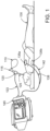
- Figure 1 is a diagram showing ventilation monitoring device 145 and subject 130 intubated with an endotracheal tube 125 according to an example.
- a tracheal tube is a catheter that is inserted into the trachea of subject 130 to establish and maintain an open airway and to ensure adequate exchange of oxygen and carbon dioxide.
- An endotracheal tube such as endotracheal tube 125 is a specific type of tracheal tube that is usually inserted through the subject's mouth or nose. Many types of tracheal tubes such as endotracheal tube 125 may be used with embodiments of the present technology. For example, airway management tubes from King Systems of Noblesville, Indiana such as the King LT(S)-D airway tube or the Combitube TM from Covidien of Mansfield, Massachusetts may be used.
- Ventilation bag 110 coupled with the ventilation bag connector 115, capnography sensor 120 and endotracheal tube 125 allows air to be forced into the subject's lungs as ventilation bag 110 is squeezed. Ventilation bag 110 may be equipped with a valve to allow the subject's exhalation gases to be released into the air without the possibility of backflow into ventilation bag 110. The assembly permits gases exchanged with the subject's lungs to flow through and be monitored by capnography sensor 120.
- a capnography sensor such as capnography sensor 120 monitors the concentration or partial pressure of carbon dioxide (CO 2 ) in the respiratory gases of the subject.
- Capnography sensor 120 communicates information related to the subject's respiratory gases such as CO 2 concentration in mm HG, end-tidal CO 2 , inspired CO 2 and respiratory rate to ventilation monitoring device 145 through communication cable 123.
- CO 2 carbon dioxide
- Capnography sensors on the market today may be used with embodiments of the present technology including but not limited to the Capnostat ® 3 or Capnostat ® 5 Mainstream CO 2 Sensors manufactured by Respironics, Inc. of Murrysville, Pennsylvania.
- Communication cable 123 may be any type of communication cable or set of wires, which allows data to be exchanged between ventilation monitoring device 145 and capnography sensor 123 such as but not limited to an RS-232 cable, Universal Serial Bus (USB) cable or Ethernet cable.
- Communication between ventilation monitoring device 145 and capnography sensor 123 may be a wireless communication channel such as but not limited to IEEE 802.11 wireless local area network (WLAN) or low-power radio frequency (RF) communication such as Bluetooth.
- WLAN wireless local area network
- RF radio frequency
- Electrodes 135a and 135b are electrically coupled with ventilation monitoring device 145 using cables 138 and 142, respectively, as shown in Figure 1 . Electrodes 135a and 135b are positioned across the subject's thoracic cavity and attached to the subject, one electrode anterior and the other electrode posterior, for example. In the embodiment, electrodes 135a and 135b are electro-cardiogram (ECG) signal pickup electrodes, but electrodes 135a and 135b may be any type of suitable electrodes capable of measuring a thoracic impedance of a subject.
- ECG electro-cardiogram
- the ventilation monitoring device 145 is configured with electrodes 135a and 135b to monitor changes in the transthoracic impedance of subject 130. If endotracheal tube 125 is properly placed in the subject's trachea and the subject's lungs are ventilated using ventilation bag 110, ventilation monitoring device 145 will detect a change in impedance across the subject's thorax between electrodes 135a and 135b. If the endotracheal tube 125 has not been properly placed, for example, it was placed in the subject's esophagus, or has become dislodged, ventilation monitoring device 145 will not measure any significant impedance change across the subject's thorax and a corresponding indication may be conveyed to the user.
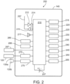
- FIG. 2 is a block diagram of system 200 comprising ventilation monitoring device 145, capnography sensor 120 and electrodes 135a and 135b according to an example.
- ventilation monitoring device 145 is a dedicated ventilation monitor comprising examples of the present technology for at least the purpose of determining whether a subject's tracheal tube is properly placed.
- ventilation monitoring device 145 is a part of a medical monitor and/or defibrillator such as the Zoll E-Series Monitor Defibrillator manufactured by Zoll Medical Corporation of Chelmsford, Massachusetts, which further comprises examples of the present technology.
- ventilation monitoring device 145 comprises at least one processor such as processor 210 and at least one memory such as volatile memory 225 or a non-volatile memory 230 including computer program code, which is configured to determine whether a subject's tracheal tube is properly placed. Volatile memory 225 and/or a non-volatile memory 230 may be removable by a user.
- Volatile memory 225 may comprise a cache area for the temporary storage of data.
- Non-volatile memory 230 may further comprise an electrically erasable programmable read only memory (EEPROM), flash memory, and/or the like.
- ventilation monitoring device 145 may use memory to store information and/or data including computer program code to implement one or more features of ventilation monitoring device 145 including but not limited to computer program code for determining whether an intubated subject's tracheal tube is properly placed.
- Ventilation monitoring device 145 may comprise at least one processor such as processor 210 and at least one other processing component.
- Processor 210 may comprise circuitry for implementing medical monitoring features such as determining whether an intubated subject's tracheal tube is properly placed as well as other medical monitor functionality.
- the at least one processor 210 may comprise a digital signal processor device, a microprocessor device, a digital to analog converter, other support circuits, and/or the like.
- the processor 210 may comprise features to operate one or more software programs.
- the processor 210 may be capable of operating at least one software program to implement functionality for determining whether an intubated subject's tracheal tube is properly placed.
- the at least one software program may comprise a connectivity program to allow the ventilation monitoring device 145 to transmit and receive Internet and/or cellular data over a wired or wireless medium, such as but not limited to voice, text, email messages, location-based content, web page content, fax content and/or the like.
- the ventilation monitoring device 145 comprises at least one antenna 297 to communicate with a transmitter 213 and a receiver 212.
- Transmitter 213 and/or receiver 212 are coupled with a network interface 214 for transmitting and receiving data with devices such as other medical equipment or emergency medical services centers.
- Processor 210 may be configured to provide at least one signal to the transmitter 213 and receive at least one signal from receiver 212.
- transmitter 213 and/or receiver 212 coupled with network interface 214 may be configured to transmit and receive analog and/or digital voice communications such as with emergency medical personnel.
- the ventilation monitoring device 145 may further comprise an identifier, such as international mobile equipment identification (IMEI) code, capable of uniquely identifying itself.
- IMEI international mobile equipment identification
- the processor 210 using the stored instructions, may determine an identity, e.g., using cell identification information.
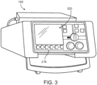
- Ventilation monitoring device 145 further comprises a user interface 215, which may include at least one input and/or output device coupled with processor 210 such as but not limited to a display such as display 220, touch screen, keyboard, keypad, mouse and/or the like.
- display 220 shown in Figure 2 and Figure 3 coupled with processor 210 is capable of displaying at least one of an indication of a subject's breath, a representation of a subject's breathing pattern and information related to a determination of whether an intubated subject's tracheal tube is properly placed.
- a keypad, keyboard, buttons and/or other input features such as soft keys 216 of Figure 3 enables a user to configure ventilation monitoring device 145 to perform functions such as confirming whether a breath has been detected during an auscultation. Further, the keypad or keyboard may enable a user to compose text-based messages and communicate with other users such as emergency medical personnel.
- ventilation monitoring device 145 further comprises a speaker 217 and/or a microphone 280.
- Speaker 217 may enable the ventilation monitoring device to provide voice instructions to a user.
- Microphone 280 may enable a user to speak with emergency medical personnel via network interface 214 at an emergency response facility.
- ventilation monitoring device 145 is a medical monitoring device further comprising features such as electrocardiogram (ECG) monitoring and/or defibrillation.
- ventilation monitoring device 145 may comprise ECG monitoring unit 235 and/or defibrillation unit 240.
- ventilation monitoring device 145 further comprises at least one power supply such as battery 207 for providing power to ventilation monitoring device 145 and/or for charging defibrillation unit 240.
- Ventilation monitoring device 145 may further comprise a location determining unit 245.
- Location determining unit 245 may comprise a global positioning system (GPS) receiver 250 for receiving a geographic location of ventilation monitoring device 145.
- Location determining unit 245 may use cell identification information, for example, to determine a geographic location for ventilation monitoring device 145.
- Ventilation monitoring device 145 may further comprise programmable timer 255 for determining intervals of time such as a time period between indications of a subject's breath.
- GPS global positioning system
- System 200 may comprise a capnography sensor 120 and/or electrodes 135a and 135b.
- either a capnography sensor or electrodes configured with system 200 to determine transthoracic impedance may be used to detect a subject's breath.
- both a capnography sensor and electrodes may be used simultaneously with system 200 to detect a subject's breath. Using both a capnography sensor and electrodes together may increase the reliability of breath detection. For example, if a capnography sensor such as capnography sensor 120 becomes dislodged from the subject tracheal or malfunctions, electrodes 135a and 135b may be used as a fallback or redundant means to detect a subject's breath. Likewise, if either electrodes 135a or 135b become disconnected from the subject, capnography sensor 120 may be used as a fallback or redundant means to detect a subject's breathe.
- processor 210 may configure and/or calibrate capnography sensor 120 for use with ventilation monitoring device 145.
- processor 210 is configured with at least one memory such as non-volatile memory 225 to detect at least one indication of a subject's breath by receiving information related to the subject's respiratory gases such as CO 2 concentration, end-tidal CO 2 , inspired CO 2 and respiratory rate from capnography sensor 120.
- ventilation monitoring device 145 may comprise a capnography sensor interface 275, which may include a device driver configured with processor 210 to read one or more memory locations from capnography sensor 120 in order to receive at least one indication of the subject's breath.
- processor 210 may initially configure and/or calibrate electrodes 135a and 135b for use with ventilation monitoring device 145.
- processor 210 is configured with at least one memory to detect at least one indication of a subject's breath by receiving impedance information from electrode 135a and 135b via electrodes interface 270 using principles described in U.S. Patent 7,925,339 .
- an indication from capnography sensor 120 of a subject's breath alone is sufficient evidence for processor 200 to determine that an intubated subject's tracheal tube is properly placed.
- an indication via electrodes 135a and 135b of a subject's breath alone is sufficient evidence for processor 200 to determine that an intubated subject's tracheal tube is properly placed.
- an indication of a subject's breath from both capnography sensor 120 and via electrodes 135a and 135b is required for processor 200 to determine that an intubated subject's tracheal tube is properly placed.
- an indication from at least one of capnography sensor 120 and electrodes 135a and 135b along with a confirmation from a user of a positive result of at least one auscultation is required for processor 200 to determine that an intubation subject's tracheal tube is properly placed.
- the term "auscultation” as used herein means manual auscultation performed by a medical professional in the conventional sense.
- acoustic cardiography performed by a device such as an Audicor ® manufactured by Inovise Medical, Inc. of Portland, Oregon may be used in place of manual auscultation to determine breath sounds or in some cases, a lack thereof.
- "auscultation” as used herein may mean utilizing a device such as an Audicor ® to perform a diagnostic technique such as cardiography on a subject to record and algorithmically interpret acoustical data to determine evidence of breath sounds or a lack thereof.
- ventilation monitoring device 145 comprises at least one accelerometer such as accelerometer 285 coupled with processor 210 for detecting movement of the ventilation monitoring device 145.
- system 200 comprises an accelerometer such as accelerometer 287, which is external to but communicatively coupled with ventilation monitoring device 145 capable of detecting movement of subject 130.
- accelerometer 287 may be coupled with capnography sensor 120, tracheal tube 125, subject 130, the subject's stretcher or bed or other locations on or near subject 130.
- the at least one processor 210 and at least one memory 225 including computer program code are configured to receive a value from accelerometer 285 and/or accelerometer 287 related to motion of ventilation monitoring device 145 and/or subject 130, respectively, and provide a prompt to a user when the value exceeds a predetermined threshold.
- a value from an accelerometer which exceeds a predetermined threshold may indicate that subject 130 and/or ventilation monitoring device 145 received one or more mechanical shocks, for example, if ventilation monitoring device 145 or a stretcher carrying subject 130 was bumped against a wall during emergency transportation of subject 130.
- a user may be prompted to inspect the subject's tracheal tube or execute ventilation monitor testing using ventilation monitoring device 145 to be sure the tracheal tube did not become dislodged.
- Figure 4 shows an initial screen 430 of the ventilation monitoring device 145 of Figure 1 according to an example .
- an initial screen such as initial screen 430 may be displayed after ventilation monitoring device 145 is powered-up and completes a self-test.
- an initial screen such as initial screen 430 may be displayed at any point when the user selects the ventilation monitor feature on the device.
- An initial screen of ventilation monitoring device 145 may comprise, for example, instructions to be performed by a user, user interface configurable parameters, status and/or the like.
- initial screen 430 comprises instructions informing a user of ventilation monitoring device 145 to (1) prepare the subject and ventilation monitoring system, (2) test and confirm that the subject was intubated properly and (3) monitor ventilations.
- initial screen 430 further comprises a set of menu options "start ventilations", “Settings” and “Exit”, which correspond to buttons 410, 412 and 420, respectively.
- Buttons 410, 412 and 420 may be known as “soft keys” in the art since each key may correspond to multiple functions such that the present function of each key is related to the screen the user is presently viewing.
- the present function of a soft key such as soft key 412 is indicated by the description such as "Settings", which is located adjacent to the button.
- the user presses "Start Ventilations” soft key 410 once the subject has been intubated and ventilation monitoring is to begin.
- a user may press the "Exit” soft key 420 to end ventilation monitoring.
- Figure 5 is a diagram of a settings screen 500 of a ventilation monitoring device 145 according to an example .
- a user may modify one or more parameters related to the configuration of ventilation monitoring device 145.
- soft key 510 corresponding to the configurable parameter, "Source” enables a user to specify whether a capnography sensor, electrodes or both a capnography sensor and electrodes will be used with ventilation monitor. Further, “Source” may enable a user to specify that "either" the capnography sensor or electrodes may determine that a breath has been detected.
- soft key 512 corresponding to the configurable parameter, "Mode” may be used to set the ventilation monitor device 145 to a manual mode or automatic mode.
- a manual mode a user must press a "confirm” soft key for each auscultation performed on the subject, which indicates a positive result.
- an automatic mode a user may press a "confirm” soft key only once when all auscultations are performed on the subject and corresponding breaths were detected during each auscultation.
- soft key 514 enables a user to set the number of auscultations, which will be performed to 3 or 5. If a user chooses 3 auscultations, then ventilation monitor device 145 will prompt the user to auscultate the subject's left lung, right lung and abdomen. If a user chooses 5 auscultations, then ventilation monitor device 145 will prompt the user to auscultate the subject's left lung, left axillary right lung, right axillary and abdomen.
- soft key 516 configures a timer for all tests performed.
- timer such as timer 255 of Figure 2 may be set to 15, 30, 45, 60 or 90 seconds.
- all of the tests being performed on the subject must be completed within the configured time limit or else a failure status for the testing will be reported.
- each one of the tests being performed on the subject must be completed within the configured time limit or else a failure status for the testing will be reported.
- the timer may be reset after each successful test.
- a user may press the "Exit" soft key 520 to exit the settings screen.
- FIG. 6 is a diagram of a testing screen 600 of ventilation monitoring device 145 showing testing in progress, ventilation monitoring device 145 configured in a manual mode for use with capnography sensor 120 and a protocol comprising three auscultations according to an example.
- the source is configured to "CO 2 " using soft key 610, which means that only the capnography sensor 120 of Figures 1 and 2 will be used as an automated means to detect the subject's breath.
- Manual mode which requires the user to confirm a positive result of each auscultation performed using soft key 618, is configured by the user using soft key 612.
- the 3-auscultation protocol which includes user auscultations of the left lung, right lung and abdomen, is configured by the user using soft key 614. At any point, the testing may be canceled by using soft key 620.
- capnograph 605 is displayed on testing screen 600. If a capnography sensor was not being used, i.e., "Source” corresponding to soft key 610 was configured to "Electrodes”, then a capnograph would not be displayed and a transthoracic impedance graph would be displayed instead. If both the capnography sensor 120 and electrodes 135a and 135b were being used i.e. "Source:” was configured to "both”, then both the capnograph and transthoracic impedance graph may be displayed on screen 600.
- the present status 610 of the testing indicates "Waiting for ventilation", which means that ventilation monitoring device 145 is waiting for capnography sensor 120 to detect a positive air flow from ventilation bag 110 of Figure 1 .
- the results of Test 1 630 indicate that the test passed.
- the results of Test 1 630 further show that a confirmation was provided by the user that subject's left lung was auscultated and 4 breaths were detected by capnography sensor 120.
- Test timer 255 which was originally set to 60 seconds using soft key 616, indicates that there are 35 seconds left in the overall testing period including the time to complete Test 2 and Test 3. If Test 2 and Test 3 are not completed within the time period left, which is 35 seconds, then the overall testing will fail and Status 610 will report "Failed" and the reasons for the failure.
- FIG 7 is a diagram of a testing screen 700 on ventilation monitoring device 145 showing the testing has passed, the ventilation monitoring device 145 configured in a manual mode for use with capnography sensor 120 and a protocol comprising three auscultations according to an example.
- screen 700 shows a continuation of the testing as shown in screen 600 of Figure 6 .
- the results of Test 2 720 indicate that the user has confirmed with soft key 618 that the subject's right lung has been auscultated and at least one breath was detected. Further, since capnography sensor 120 has detected at least one breath, 3 breaths in this case, Test 2 has passed.
- the results of Test 3 725 indicate that the user has confirmed with soft key 618 that the subject's abdomen has been auscultated and no breathing was detected. Further, since capnography sensor 120 has detected at least one breath, 2 breaths in this case, Test 3 has passed. Since each of Test 1, Test 2 and Test 3 have passed; overall status 710 indicates that the testing has passed. In an embodiment, the results of the overall testing including the results of each of the Tests, e.g. Test 1, Test 2 and Test 3, are saved in memory, for example, in a FLASH memory such as non-volatile memory 230 of Figure 2 . At this point, the user may exit the Ventilation Monitor Testing by pressing soft key 620.
- FIG 8 is a diagram of a testing screen 800 on ventilation monitoring device 145 showing that the testing has failed, the ventilation monitoring device 145 configured in a manual mode for use with capnography sensor 120 and a protocol comprising three auscultations according to an example.
- screen 800 shows a continuation of the testing as shown in screen 600 of Figure 6 .
- the results of Test 3 825 indicate that the test has failed, which has caused the overall testing Status 810 to indicate failure.
- the capnography sensor 145 detected 12 breaths of the subject, the user did not confirm a positive result of the subject's abdominal auscultation in Test 3 using soft key 618 within the timer period.
- test timer 255 counted down to 0 as indicated at 815 and the overall testing failed.
- Reasons for the failure of the overall testing 812 indicate that the timer expired and that a confirmation in Test 3 was not received.
- Figure 9 is a diagram of a testing screen 900 on ventilation monitoring device 145 showing that the testing has failed, the ventilation monitoring device 145 configured in a manual mode for use with capnography sensor 120 and a protocol comprising five auscultations according to an example
- screen 900 shows that a user configured the ventilation monitor testing using soft key 614 to require 5 auscultations to be performed on the subject including auscultations of the subject's left lung, right lung, abdomen, left axillary and right axillary.
- Testing screen 900 shows that Tests 1 through 4 have passed, however, Test 5 has failed.
- Test 5 925 although the user confirmed that at least one breath was detected during auscultation of the subject's right axillary, capnography sensor 120 did not detect at least one breath.
- Screen 900 shows the results of Test 5 925, which indicate that the subject's breath count did not increment (remained at 0) and Test 5 failed as a result.
- the failure of a capnography sensor to detect a breath may be due to a number of reasons such as endotracheal tube 125 of Figure 1 becoming dislodged from the subject's trachea or the subject may have stopped breathing.
- test timer 255 counted down to 0 as indicated at 915 and triggered a failure of the overall testing 910.
- Screen 900 further indicates that reasons 912 for the failure of the overall testing was that the timer expired and no breath was detected in Test 5.
- FIG 10 is a diagram of a testing screen 1000 on ventilation monitoring device 145 showing that the testing has failed, the ventilation monitoring device 145 configured in a manual mode for use with capnography sensor 120, electrodes 135a and 135b, and a protocol comprising five auscultations according to an example.
- screen 1000 shows that a user configured the ventilation monitor testing using soft key 614 to require 5 auscultations to be performed on the subject including auscultations of the subject's left lung, right lung, abdomen, left axillary and right axillary.
- screen 1000 shows that the user configured the source 610 to be both the capnography sensor 120 and electrodes 135a and 135b of Figure 1 .
- both a capnograph 1005 and transthoracic impedance waveform 1007 are shown in screen 1000.
- Testing screen 1000 shows that Tests 1 through 3 have passed, however, Test 4 has failed.
- Test 4 although the user confirmed that at least one breath was detected during auscultation of the subject's left axillary, system 200 configured with capnography sensor 120 and electrodes 135a and 135b indicted a failure to detect a breath from subject 130. Since source 1030 is set to "both", the system 200 must detect a breath from both capnography sensor 120 and electrodes 135a and 135b.
- Screen 1000 shows the results of Test 4 1025, which indicate that the subject's breath count did not increment (remained at 0) and Test 4 failed as a result.
- Screen 1000 further indicates that reasons 1012 for the failure of the overall testing was that the timer expired and no breath was detected in Test 4 with respect to the transthoracic impedance testing using electrode 135a and 135b. Since source 1030 was set to "both", even though system 200 may have detected a breath using capnography sensor 120, the overall testing failed since no breath was detected with respect to the transthoracic impedance testing.
- the failure of the transthoracic impedance to detect a breath may be due to a number of reasons such as electrode 135a or electrode 135b becoming disconnected from the subject's chest or back or the subject may be in repertory distress.
- test timer 1015 counted down to 0 and triggered a failure of the overall testing indicated at 1010.
- test 4 could pass providing that system 200 detected a breath using either capnography sensor 120 or transthoracic impedance testing and the user confirmed the presence of a breath by auscultation.
- FIG 11 is a diagram of a testing screen 1100 on ventilation monitoring device 145 showing that the testing has passed, the ventilation monitoring device 145 configured in an automatic mode for use with capnography sensor 120, electrodes 135a and 135b, and a protocol comprising five auscultations according to an example
- Screen 1100 shows that the user configured the mode to be automatic using soft key 612.
- the user may confirm a positive result for each of the auscultations performed by pressing confirm soft key 618 once when the auscultations are completed but before the expiration of test timer 255 at indicated at 1115.
- the user confirmed a positive result for each of the auscultations as indicated in result of Test 5 1125.
- Testing screen 1100 shows that each of Tests 1 through 5 has passed and the status 1110 for the testing indicates "Passed".
- Figure 12 is a flow diagram depicting a method 1200 according to an example.
- Method 1200 begins at 1205.
- a timer is set.
- the timer is a programmable timer such as programmable timer 255 of Figure 2 .
- the timer may be set to expire in a range between 30 and 90 seconds, however, other time periods are possible.
- the determination may be made by a computer or medical monitor such as system 200 of Figure 2 configured with a capnography sensor such as capnographic sensor 120 of Figure 1 or by determining a transthoracic impedance of the subject using, for example, electrodes 135a and 135b of Figure 1 configured with system 200.
- system 200 may require indications of a subject's breath to be received from both the capnography sensor and electrodes 135a and 135b for the determination of the subject's breath to be made.
- an indication of the subject's breath from one sensor only is necessary for system 200 to make the determination.
- a technical effect of one or more of the example embodiments disclosed herein is to provide a system for monitoring ventilation of a subject and determining whether a tracheal tube such as an endotracheal tube has been properly inserted in a subject's trachea.
- Examples of the present technology may be implemented in software, firmware, hardware, application logic or a combination of software, hardware and application logic.
- the software, firmware, application logic and/or hardware may reside on at least one system such as system 200 of Figure 2 .
- the application logic, software or an instruction set is maintained on any one of various conventional computer-readable media.
- a "computer-readable medium” may be any media or means that can contain, store, communicate, propagate or transport the instructions for use by or in connection with an instruction execution system, apparatus, or device, such as a computer, with one example of a computer, system 200, described and depicted in Figure 2 .
- a computer-readable medium may comprise a computer-readable storage medium that may be any media or means that can contain or store the instructions for use by or in connection with an instruction execution system, apparatus, or device, such as in system 200 of Figure 2 .
- the different functions discussed herein may be performed in a different order and/or concurrently with each other. Furthermore, if desired, one or more of the above-described functions may be optional or may be combined.
Landscapes
- Health & Medical Sciences (AREA)
- Life Sciences & Earth Sciences (AREA)
- Engineering & Computer Science (AREA)
- Biomedical Technology (AREA)
- Animal Behavior & Ethology (AREA)
- General Health & Medical Sciences (AREA)
- Public Health (AREA)
- Veterinary Medicine (AREA)
- Pulmonology (AREA)
- Heart & Thoracic Surgery (AREA)
- Emergency Medicine (AREA)
- Surgery (AREA)
- Medical Informatics (AREA)
- Molecular Biology (AREA)
- Physics & Mathematics (AREA)
- Biophysics (AREA)
- Pathology (AREA)
- Anesthesiology (AREA)
- Hematology (AREA)
- Physiology (AREA)
- Nuclear Medicine, Radiotherapy & Molecular Imaging (AREA)
- Radiology & Medical Imaging (AREA)
- Cardiology (AREA)
- Obesity (AREA)
- Measurement Of The Respiration, Hearing Ability, Form, And Blood Characteristics Of Living Organisms (AREA)
- Neurology (AREA)
- Electrotherapy Devices (AREA)
- Measuring And Recording Apparatus For Diagnosis (AREA)
Claims (14)
- Ein Beatmungsüberwachungssystem (200), umfassend:einen Kapnographiesensor (120), der so konfiguriert ist, dass er Informationen bereitstellt, die für einen Atemzug einer Person (130) repräsentativ sind; undmindestens einen Prozessor (210), der mit dem Kapnographiesensor (120) in Verbindung steht, wobei der mindestens eine Prozessor (210) so konfiguriert ist, dass er:Signale von dem Kapnographiesensor (120) empfängt und verarbeitet, die für den Atem des Patienten repräsentativ sind, während ein Endotrachealtubus (125) in einer Luftröhre des Patienten (130) positioniert ist,die empfangenen und verarbeiteten Signale überwacht, um ein oder mehrere Anzeichen für den Atem des Patienten zu identifizieren; undeine Aufforderung an einen Benutzer sendet, den Endotrachealtubus (125) zu untersuchen, um festzustellen, ob sich der Endotrachealtubus (125) aufgrund des identifizierten einen oder der identifizierten mehreren Anzeichen für den Atem des Patienten verschoben hat;dadurch gekennzeichnet, dassferner mindestens einen Beschleunigungsmesser (285, 287) umfasst ist, der mit dem mindestens einen Prozessor (210) in Verbindung steht und so konfiguriert ist, dass er eine Bewegung des mindestens einen Endotrachealtubus (125), des Kapnographiesensors (120) oder des Patienten (130) erfasst; und dassder mindestens eine Prozessor (210) ferner so konfiguriert ist, dass erSignale von dem mindestens einen Beschleunigungsmesser (285, 287) empfängt und verarbeitet; einen Wert bestimmt, der für die Bewegung des Endotrachealtubus (125), des Kapnographiesensors (120) oder des Patienten (130) repräsentativ ist, basierend auf den empfangenen und verarbeiteten Signalen von dem mindestens einen Beschleunigungsmesser (285, 287); unddem Benutzer die Aufforderung zur Überprüfung des Endotrachealtubus (125) gibt, wenn der ermittelte Wert, der für die Bewegung repräsentativ ist, größer als ein vorbestimmter Schwellenwert ist.
- Das Beatmungsüberwachungssystem (200) nach Anspruch 1, wobei der Kapnographiesensor (120) so konfiguriert ist, dass er eine Konzentration oder einen Partialdruck von Kohlendioxid in Atemgasen des Patienten (130) misst.
- Das Beatmungsüberwachungssystem (200) nach Anspruch 1 oder Anspruch 2, wobei der Kapnographiesensor (120) so konfiguriert ist, dass er mindestens eine der folgenden Größen misst: Kohlendioxidkonzentration (CO2), endexspiratorisches CO2, eingeatmetes CO2 oder Atemfrequenz der Person (130).
- Das Beatmungsüberwachungssystem (200) nach einem der Ansprüche 1 - 3 umfasst ferner den Endotrachealtubus (125), der in der Luftröhre des Patienten positioniert ist, wobei der Kapnographiesensor (120) in Fluidverbindung mit dem Endotrachealtubus (125) steht.
- Das Beatmungsüberwachungssystem (200) nach Anspruch 4, das ferner einen Beatmungsbeutel (110) umfasst, der mit dem Endotrachealtubus (125) und dem Kapnographiesensor (120) strömungsmäßig verbunden ist, um Luft durch den Endotrachealtubus (125) in die Lungen des Patienten (130) zu leiten.
- Das Beatmungsüberwachungssystem (200) nach einem der Ansprüche 1 - 5, wobei die Aufforderung ausgegeben wird, wenn innerhalb eines vorgegebenen Zeitraums keine Anzeichen für die Atmung der Person festgestellt werden.
- Das Beatmungsüberwachungssystem (200) nach einem der Ansprüche 1 - 5, das ferner mindestens einen transthorakalen Impedanzsensor (135a, 135b) umfasst, der mit dem mindestens einen Prozessor (210) in Verbindung steht, der so konfiguriert ist, dass er eine transthorakale Impedanz des Patienten (130) misst, wobei der mindestens eine Prozessor (210) so konfiguriert ist, dass erSignale von dem mindestens einen transthorakalen Impedanzsensor (135a, 135b) empfängt und verarbeitet;die empfangenen und verarbeiteten Signale von dem mindestens einen transthorakalen Impedanzsensor (135a, 135b) und von dem mindestens einen Kapnographiesensor (120) überwacht, um eine oder mehrere Anzeigen des Atems der Person zu identifizieren; unddem Benutzer basierend auf dem einen oder den mehreren Anzeichen des Atems des Patienten, die aus den Signalen des Kapnographiesensors (120) und den Signalen des mindestens einen transthorakalen Impedanzsensors (135a, 135b) identifiziert wurden, eine Aufforderung bereitstellt.
- Das Beatmungsüberwachungssystem (200) nach einem der Ansprüche 1 - 5 umfasst ferner eine erste transthorakale Impedanzelektrode (135a), die so konfiguriert ist, dass sie auf einer ersten Seite einer Brusthöhle des Patienten (130) positioniert werden kann und eine zweite transthorakale Impedanzelektrode (135b), die so konfiguriert ist, dass sie auf einer zweiten gegenüberliegenden Seite der Brusthöhle des Patienten (130) positioniert werden kann, um die transthorakale Impedanz des Patienten (130) zu messen.
- Das Beatmungsüberwachungssystem (200) nach einem der Ansprüche 1 - 5, das ferner mindestens ein akustisches Kardiographiegerät umfasst, das mit dem mindestens einen Prozessor (210) in Verbindung steht und so konfiguriert ist, dass es Atemgeräusche des Patienten (130) misst, wobei der mindestens eine Prozessor (210) so konfiguriert ist, dass er:Signale von dem mindestens einen akustischen Kardiographiegerät empfängt und verarbeitet;die empfangenen und verarbeiteten Signale von der mindestens einen akustischen Kardiographievorrichtung und von dem Kapnographiesensor (120) überwacht, um eine oder mehrere Atemindikationen der Person zu identifizieren.
- Das Beatmungsüberwachungssystem (200) nach Anspruch 9, wobei die mindestens eine akustische Kardiographievorrichtung so konfiguriert ist, dass sie Atemgeräusche für mindestens eine der folgenden Regionen misst: linke Lunge, rechte Lunge, linker Achselbereich, rechter Achselbereich oder Bauch des Patienten (130).
- Das Beatmungsüberwachungssystem (200) nach einem der Ansprüche 1 bis 10, wobei der Prozessor konfiguriert ist, eine Indikation eines positiven Ergebnisses einer Auskultation des Patienten zu empfangen, und wobei die Aufforderung ausgegeben wird, wenn innerhalb des vorgegebenen Zeitraums kein Anzeichen für ein positives Ergebnis der Auskultation vorliegt.
- Das Beatmungsüberwachungssystem (200) nach Anspruch 11, wobei der mindestens eine Prozessor (210) so konfiguriert ist, dass er eine Auswahl des Benutzers für eine Dauer des vorbestimmten Zeitraums empfängt, wobei die Dauer aus 15 Sekunden, 30 Sekunden, 45 Sekunden, 60 Sekunden oder 90 Sekunden ausgewählt wird.
- Das Beatmungsüberwachungssystem (200) nach einem der Ansprüche 1 - 12 umfasst ferner eine Defibrillatoreinheit (240), die mit dem mindestens einen Prozessor (210) in Verbindung steht.
- Ein Verfahren zum Überwachen der Platzierung eines Endotrachealtubus (125), der in einer Luftröhre eines Patienten (130) positioniert ist, das von mindestens einem Prozessor (210) eines Beatmungsüberwachungssystems (200) durchgeführt wird, wobei das Verfahren Folgendes umfasst:Empfangen und Verarbeiten von Signalen, die den Atem des Patienten (130) darstellen, von einem Kapnographiesensor (120) des Beatmungsüberwachungssystems (200), der so konfiguriert ist, dass er Informationen bereitstellt, die den Atem eines Patienten (130) darstellen, während der Endotrachealtubus (125) in der Luftröhre des Patienten positioniert ist;Überwachen der empfangenen und verarbeiteten Signale, um ein oder mehrere Anzeichen für den Atem des Patienten zu identifizieren; undBereitstellen einer Aufforderung an einen Benutzer, den Endotrachealtubus (125) zu untersuchen, um festzustellen, ob sich der Endotrachealtubus (125) aufgrund des identifizierten einen oder der mehreren Anzeichen für den Atem des Patienten verschoben hat;gekennzeichnet durchErfassen einer Bewegung des mindestens einen Endotrachealtubus (125), des Kapnographiesensors (120) oder der Person (130) durch mindestens einen Beschleunigungsmesser (285, 287), der mit dem mindestens einen Prozessor (210) in Verbindung steht;Empfangen und Verarbeiten von Signalen von dem mindestens einen Beschleunigungsmesser (285, 287);Bestimmen eines Wertes, der für die Bewegung des Endotrachealtubus (125), des Kapnographiesensors (120) oder des Patienten (130) repräsentativ ist, basierend auf den empfangenen und verarbeiteten Signalen von dem mindestens einen Beschleunigungsmesser (285, 287); undBereitstellen der Aufforderung an den Benutzer, den Endotrachealtubus (125) zu untersuchen, wenn der bestimmte Wert, der für die Bewegung repräsentativ ist, größer als ein vorbestimmter Schwellenwert ist.
Applications Claiming Priority (4)
| Application Number | Priority Date | Filing Date | Title |
|---|---|---|---|
| US201261740789P | 2012-12-21 | 2012-12-21 | |
| EP19169495.9A EP3530185B1 (de) | 2012-12-21 | 2013-12-17 | Beatmungsüberwachung |
| PCT/US2013/075776 WO2014099986A1 (en) | 2012-12-21 | 2013-12-17 | Ventilation monitoring |
| EP13863754.1A EP2934317B1 (de) | 2012-12-21 | 2013-12-17 | Beatmungsüberwachung |
Related Parent Applications (3)
| Application Number | Title | Priority Date | Filing Date |
|---|---|---|---|
| EP13863754.1A Division EP2934317B1 (de) | 2012-12-21 | 2013-12-17 | Beatmungsüberwachung |
| EP19169495.9A Division EP3530185B1 (de) | 2012-12-21 | 2013-12-17 | Beatmungsüberwachung |
| EP19169495.9A Division-Into EP3530185B1 (de) | 2012-12-21 | 2013-12-17 | Beatmungsüberwachung |
Publications (2)
| Publication Number | Publication Date |
|---|---|
| EP4074254A1 EP4074254A1 (de) | 2022-10-19 |
| EP4074254B1 true EP4074254B1 (de) | 2025-02-05 |
Family
ID=50975458
Family Applications (3)
| Application Number | Title | Priority Date | Filing Date |
|---|---|---|---|
| EP22177836.8A Active EP4074254B1 (de) | 2012-12-21 | 2013-12-17 | Beatmungsüberwachung |
| EP19169495.9A Active EP3530185B1 (de) | 2012-12-21 | 2013-12-17 | Beatmungsüberwachung |
| EP13863754.1A Active EP2934317B1 (de) | 2012-12-21 | 2013-12-17 | Beatmungsüberwachung |
Family Applications After (2)
| Application Number | Title | Priority Date | Filing Date |
|---|---|---|---|
| EP19169495.9A Active EP3530185B1 (de) | 2012-12-21 | 2013-12-17 | Beatmungsüberwachung |
| EP13863754.1A Active EP2934317B1 (de) | 2012-12-21 | 2013-12-17 | Beatmungsüberwachung |
Country Status (5)
| Country | Link |
|---|---|
| US (3) | US10220169B2 (de) |
| EP (3) | EP4074254B1 (de) |
| JP (1) | JP2016506269A (de) |
| CN (1) | CN104918549A (de) |
| WO (1) | WO2014099986A1 (de) |
Families Citing this family (26)
| Publication number | Priority date | Publication date | Assignee | Title |
|---|---|---|---|---|
| US9248306B2 (en) | 1999-09-30 | 2016-02-02 | Physio-Control, Inc. | Pulse detection apparatus, software, and methods using patient physiological signals |
| EP4074254B1 (de) * | 2012-12-21 | 2025-02-05 | Zoll Medical Corporation | Beatmungsüberwachung |
| US10272010B2 (en) | 2015-03-20 | 2019-04-30 | Zoll Medical Corporation | Systems and methods for testing a medical device |
| EP3273857B1 (de) * | 2015-03-27 | 2021-01-27 | Zoll Medical Corporation | Systeme und verfahren zur positionierung eines intubationstubus |
| US11266776B2 (en) | 2015-10-30 | 2022-03-08 | Medtronic Xomed, Inc. | Method and apparatus for irrigation |
| US20170119953A1 (en) | 2015-10-30 | 2017-05-04 | Medtronic Xomed, Inc. | Method and Apparatus for Irrigation |
| US11709747B2 (en) | 2016-01-08 | 2023-07-25 | Zoll Medical Corporation | Patient assurance system and method |
| US11617538B2 (en) | 2016-03-14 | 2023-04-04 | Zoll Medical Corporation | Proximity based processing systems and methods |
| US11433211B2 (en) * | 2016-03-17 | 2022-09-06 | Zoll Medical Corporation | Flow sensor for ventilation |
| US10426342B2 (en) | 2016-03-31 | 2019-10-01 | Zoll Medical Corporation | Remote access for ambulatory medical device |
| GB2549263A (en) * | 2016-04-05 | 2017-10-18 | Cambridge Respiratory Innovations Ltd | Capnometer |
| US10799152B2 (en) * | 2016-08-11 | 2020-10-13 | Medtronic Xomed, Inc. | System and method for motion detection and accounting |
| CN206526368U (zh) * | 2016-12-02 | 2017-09-29 | 深圳市前海康启源科技有限公司 | 具有心电监测功能的可穿戴式监护设备 |
| US10820833B2 (en) | 2016-12-09 | 2020-11-03 | Physio-Control, Inc. | Capnograph system further detecting spontaneous patient breaths |
| US11957924B2 (en) * | 2017-11-30 | 2024-04-16 | Hamad Medical Corporation | Airway cardioverter-defibrillator system |
| EP4390967A3 (de) | 2018-01-17 | 2024-10-02 | Zoll Medical Corporation | Systeme und verfahren zur unterstützung der atemwegsverwaltung eines patienten |
| US11819369B2 (en) | 2018-03-15 | 2023-11-21 | Zoll Medical Corporation | Augmented reality device for providing feedback to an acute care provider |
| JP6961530B2 (ja) * | 2018-04-27 | 2021-11-05 | 日本光電工業株式会社 | 患者治療システム、及びモニタリング装置 |
| JP7174128B2 (ja) * | 2018-04-27 | 2022-11-17 | 日本光電工業株式会社 | 患者治療システム、及びモニタリング装置 |
| EP3787499A1 (de) * | 2018-04-30 | 2021-03-10 | Koninklijke Philips N.V. | Zubehördetektion bei kapnografiemodulen |
| JP7257127B2 (ja) * | 2018-11-07 | 2023-04-13 | フクダ電子株式会社 | 医療用画像表示方法及びプログラム |
| CN110201300B (zh) * | 2019-06-06 | 2020-08-25 | 北京航空航天大学 | 一种气管痉挛治疗装置 |
| EP4058117A4 (de) | 2019-11-14 | 2023-12-06 | Dorothy Owens | Sicherheitsalarm für tracheostomie-halsband |
| US20220134034A1 (en) * | 2020-10-29 | 2022-05-05 | Biosense Webster (Israel) Ltd. | Controlling ventilation of a patient based on filtered electrocardiogram measurements |
| US11642481B2 (en) * | 2020-12-23 | 2023-05-09 | Biosense Webster (Israel) Ltd. | Patient ventilation system having sensors and electrodes coupled to intubations tube |
| US20230320675A1 (en) * | 2022-04-08 | 2023-10-12 | Covidien Lp | Identification and display of airway collapse |
Citations (3)
| Publication number | Priority date | Publication date | Assignee | Title |
|---|---|---|---|---|
| WO2002045566A2 (en) * | 2000-12-07 | 2002-06-13 | Children's Medical Center Corporation | Automated interpretive medical care system and methodology |
| WO2012114262A1 (en) * | 2011-02-22 | 2012-08-30 | Koninklijke Philips Electronics N.V. | Real-time airway check status indicator |
| US20120302908A1 (en) * | 2008-10-16 | 2012-11-29 | Hemnes Anna R | Oral end tidal carbon dioxide probe for diagnosing pulmonary arterial hypertension |
Family Cites Families (28)
| Publication number | Priority date | Publication date | Assignee | Title |
|---|---|---|---|---|
| JPH0647010B2 (ja) * | 1986-03-26 | 1994-06-22 | ボ−ド・オブ・リ−ジエンツ、ザ・ユニバ−シテイ−・オブ・テキサス・システム | 気管内器具 |
| US4951678A (en) * | 1988-05-23 | 1990-08-28 | Thomas Jefferson University | Methods and apparatus for monitoring vital signs |
| CN2242700Y (zh) * | 1995-11-07 | 1996-12-18 | 李运恩 | 可视气管导管芯 |
| US6168568B1 (en) | 1996-10-04 | 2001-01-02 | Karmel Medical Acoustic Technologies Ltd. | Phonopneumograph system |
| US6224549B1 (en) * | 1999-04-20 | 2001-05-01 | Nicolet Biomedical, Inc. | Medical signal monitoring and display |
| US7294112B1 (en) * | 1999-05-13 | 2007-11-13 | Colin Dunlop | Motion monitoring apparatus |
| US8394031B2 (en) * | 2000-10-06 | 2013-03-12 | Biomedical Acoustic Research, Corp. | Acoustic detection of endotracheal tube location |
| US6616597B2 (en) * | 2000-12-12 | 2003-09-09 | Datascope Investment Corp. | Intra-aortic balloon catheter having a dual sensor pressure sensing system |
| CN1358548A (zh) * | 2000-12-20 | 2002-07-17 | 董金生 | 人体气管的插管装置 |
| US6929600B2 (en) * | 2001-07-24 | 2005-08-16 | Stephen D. Hill | Apparatus for intubation |
| NO20022960D0 (no) * | 2002-06-19 | 2002-06-19 | Medinnova Sf | Apparat og metode for intubasjonsovervåkning |
| SE0500855L (sv) * | 2005-04-18 | 2006-09-19 | Cap Safe Sweden Ab | Anordning för indikering av livsfunktion |
| US8416291B2 (en) * | 2006-08-07 | 2013-04-09 | Innovative Medical Devices, Inc. | System to aid in the positioning, confirmation and documentation of an endotracheal tube |
| US20080251070A1 (en) * | 2006-11-02 | 2008-10-16 | Vadim Pinskiy | Method and apparatus for capnography-guided intubation |
| US8038629B2 (en) * | 2007-10-02 | 2011-10-18 | Board Of Regents, The University Of Texas System | Digital endotracheal tube sound acquisition and localization device |
| EP2352425B1 (de) * | 2008-11-07 | 2019-01-02 | Koninklijke Philips N.V. | Kohlendioxid-überwachungssystem |
| GB0822592D0 (en) * | 2008-12-11 | 2009-01-21 | Univ Gent | Methods and systems for analysing resuscition |
| US20120116156A1 (en) * | 2009-04-28 | 2012-05-10 | Dror Lederman | Method and apparatus for automatic verification of endotracheal intubation |
| US20110166442A1 (en) * | 2010-01-07 | 2011-07-07 | Artann Laboratories, Inc. | System for optically detecting position of an indwelling catheter |
| CA2797852A1 (en) * | 2010-04-30 | 2011-11-03 | Vito Forte | Endotracheal cuff pressure regulation circuit and method |
| EP2756792A1 (de) * | 2010-09-08 | 2014-07-23 | Covidien LP | Katheter mit Bildgebungsanordnung |
| US20120123219A1 (en) * | 2010-11-15 | 2012-05-17 | Emil Markov Georgiev | Method and system for controlling medical monitoring equipment |
| JP5951630B2 (ja) * | 2010-12-07 | 2016-07-13 | アーリーセンス リミテッド | 臨床症状のモニター、予測、および治療 |
| RU2013142751A (ru) * | 2011-02-22 | 2015-03-27 | Конинклейке Филипс Н.В. | Капнографическая система для автоматической диагностики состояния пациента |
| US10206607B2 (en) * | 2011-04-29 | 2019-02-19 | The Board Of Regents Of The University Of Texas System | Methods and apparatus for optoacoustic guidance and confirmation of placement of indwelling medical apparatus |
| EP2707068B1 (de) * | 2011-05-23 | 2019-09-25 | Zoll Medical Corporation | Medizinisches beatmungssystem mit feedbackeinheit für beatmungsqualität |
| JP6134735B2 (ja) * | 2011-12-16 | 2017-05-24 | コーデイト・メディカル・アクチエボラーグChordate Medical AB | Ans刺激 |
| EP4074254B1 (de) * | 2012-12-21 | 2025-02-05 | Zoll Medical Corporation | Beatmungsüberwachung |
-
2013
- 2013-12-17 EP EP22177836.8A patent/EP4074254B1/de active Active
- 2013-12-17 EP EP19169495.9A patent/EP3530185B1/de active Active
- 2013-12-17 CN CN201380067658.8A patent/CN104918549A/zh active Pending
- 2013-12-17 US US14/109,519 patent/US10220169B2/en active Active
- 2013-12-17 WO PCT/US2013/075776 patent/WO2014099986A1/en not_active Ceased
- 2013-12-17 EP EP13863754.1A patent/EP2934317B1/de active Active
- 2013-12-17 JP JP2015549584A patent/JP2016506269A/ja active Pending
-
2019
- 2019-01-08 US US16/242,385 patent/US11173265B2/en active Active
-
2021
- 2021-10-21 US US17/507,018 patent/US20220152328A1/en active Pending
Patent Citations (3)
| Publication number | Priority date | Publication date | Assignee | Title |
|---|---|---|---|---|
| WO2002045566A2 (en) * | 2000-12-07 | 2002-06-13 | Children's Medical Center Corporation | Automated interpretive medical care system and methodology |
| US20120302908A1 (en) * | 2008-10-16 | 2012-11-29 | Hemnes Anna R | Oral end tidal carbon dioxide probe for diagnosing pulmonary arterial hypertension |
| WO2012114262A1 (en) * | 2011-02-22 | 2012-08-30 | Koninklijke Philips Electronics N.V. | Real-time airway check status indicator |
Non-Patent Citations (1)
| Title |
|---|
| MELISSA L LANGHAN ET AL: "A Randomized Controlled Trial of Capnography in the Correction of Simulated Endotracheal Tube Dislodgement", ACADEMIC EMERGENCY MEDICINE, HANLEY AND BELFUS, PHILADELPHIA, PA, US, vol. 18, no. 6, 15 June 2011 (2011-06-15), pages 590 - 596, XP071989250, ISSN: 1069-6563, DOI: 10.1111/J.1553-2712.2011.01090.X * |
Also Published As
| Publication number | Publication date |
|---|---|
| WO2014099986A1 (en) | 2014-06-26 |
| US20140180138A1 (en) | 2014-06-26 |
| JP2016506269A (ja) | 2016-03-03 |
| EP2934317A4 (de) | 2016-06-22 |
| EP2934317B1 (de) | 2019-05-15 |
| EP3530185B1 (de) | 2022-07-13 |
| CN104918549A (zh) | 2015-09-16 |
| US11173265B2 (en) | 2021-11-16 |
| US10220169B2 (en) | 2019-03-05 |
| EP2934317A1 (de) | 2015-10-28 |
| US20190175852A1 (en) | 2019-06-13 |
| EP3530185A1 (de) | 2019-08-28 |
| EP4074254A1 (de) | 2022-10-19 |
| US20220152328A1 (en) | 2022-05-19 |
Similar Documents
| Publication | Publication Date | Title |
|---|---|---|
| US11173265B2 (en) | Ventilation monitoring | |
| EP2352425B1 (de) | Kohlendioxid-überwachungssystem | |
| US7896814B2 (en) | Process and device for lung ventilation | |
| EP3206578B1 (de) | Modulares überwachungs- und belüftungssystem | |
| US9486157B2 (en) | Intubation monitoring apparatus and method | |
| US5620004A (en) | Airway indicator device | |
| US20160095998A1 (en) | Informative Accessories | |
| WO2019143856A2 (en) | Systems and methods for assisting patient airway management | |
| CN103491872B (zh) | 实时气道检查状态指示符 | |
| WO2017047595A1 (ja) | 呼吸状態表示装置、呼吸状態表示方法、及び呼吸状態表示プログラム | |
| CN101854972A (zh) | 呼吸机和/或麻醉机 | |
| EP4637887A1 (de) | Intelligente verwaltung einer medizinischen vorrichtung | |
| WO2011068741A1 (en) | Sensing endotracheal tube location | |
| KR102618686B1 (ko) | 인공호흡기를 이용한 중앙 모니터링 시스템 및 방법 | |
| KR102665056B1 (ko) | 기관 삽관용 튜브에 연결되는 이산화탄소 측정 디바이스, 그의 제어 방법 및 시스템 | |
| US20230191056A1 (en) | Process and apparatus for monitoring a ventilator | |
| US20230094608A1 (en) | Pendelluft detection by acoustic interferometry through an endotracheal tube | |
| JP2022016437A (ja) | 患者治療システム、及びモニタリング装置 |
Legal Events
| Date | Code | Title | Description |
|---|---|---|---|
| PUAI | Public reference made under article 153(3) epc to a published international application that has entered the european phase |
Free format text: ORIGINAL CODE: 0009012 |
|
| STAA | Information on the status of an ep patent application or granted ep patent |
Free format text: STATUS: THE APPLICATION HAS BEEN PUBLISHED |
|
| AC | Divisional application: reference to earlier application |
Ref document number: 2934317 Country of ref document: EP Kind code of ref document: P Ref document number: 3530185 Country of ref document: EP Kind code of ref document: P |
|
| AK | Designated contracting states |
Kind code of ref document: A1 Designated state(s): AL AT BE BG CH CY CZ DE DK EE ES FI FR GB GR HR HU IE IS IT LI LT LU LV MC MK MT NL NO PL PT RO RS SE SI SK SM TR |
|
| STAA | Information on the status of an ep patent application or granted ep patent |
Free format text: STATUS: REQUEST FOR EXAMINATION WAS MADE |
|
| 17P | Request for examination filed |
Effective date: 20230417 |
|
| RBV | Designated contracting states (corrected) |
Designated state(s): AL AT BE BG CH CY CZ DE DK EE ES FI FR GB GR HR HU IE IS IT LI LT LU LV MC MK MT NL NO PL PT RO RS SE SI SK SM TR |
|
| P01 | Opt-out of the competence of the unified patent court (upc) registered |
Effective date: 20230505 |
|
| STAA | Information on the status of an ep patent application or granted ep patent |
Free format text: STATUS: EXAMINATION IS IN PROGRESS |
|
| 17Q | First examination report despatched |
Effective date: 20240109 |
|
| GRAP | Despatch of communication of intention to grant a patent |
Free format text: ORIGINAL CODE: EPIDOSNIGR1 |
|
| STAA | Information on the status of an ep patent application or granted ep patent |
Free format text: STATUS: GRANT OF PATENT IS INTENDED |
|
| INTG | Intention to grant announced |
Effective date: 20240830 |
|
| GRAS | Grant fee paid |
Free format text: ORIGINAL CODE: EPIDOSNIGR3 |
|
| GRAA | (expected) grant |
Free format text: ORIGINAL CODE: 0009210 |
|
| STAA | Information on the status of an ep patent application or granted ep patent |
Free format text: STATUS: THE PATENT HAS BEEN GRANTED |
|
| AC | Divisional application: reference to earlier application |
Ref document number: 2934317 Country of ref document: EP Kind code of ref document: P Ref document number: 3530185 Country of ref document: EP Kind code of ref document: P |
|
| AK | Designated contracting states |
Kind code of ref document: B1 Designated state(s): AL AT BE BG CH CY CZ DE DK EE ES FI FR GB GR HR HU IE IS IT LI LT LU LV MC MK MT NL NO PL PT RO RS SE SI SK SM TR |
|
| REG | Reference to a national code |
Ref country code: GB Ref legal event code: FG4D |
|
| REG | Reference to a national code |
Ref country code: CH Ref legal event code: EP |
|
| REG | Reference to a national code |
Ref country code: DE Ref legal event code: R096 Ref document number: 602013086495 Country of ref document: DE |
|
| REG | Reference to a national code |
Ref country code: IE Ref legal event code: FG4D |
|
| REG | Reference to a national code |
Ref country code: NL Ref legal event code: MP Effective date: 20250205 |
|
| PG25 | Lapsed in a contracting state [announced via postgrant information from national office to epo] |
Ref country code: RS Free format text: LAPSE BECAUSE OF FAILURE TO SUBMIT A TRANSLATION OF THE DESCRIPTION OR TO PAY THE FEE WITHIN THE PRESCRIBED TIME-LIMIT Effective date: 20250505 |
|
| PG25 | Lapsed in a contracting state [announced via postgrant information from national office to epo] |
Ref country code: FI Free format text: LAPSE BECAUSE OF FAILURE TO SUBMIT A TRANSLATION OF THE DESCRIPTION OR TO PAY THE FEE WITHIN THE PRESCRIBED TIME-LIMIT Effective date: 20250205 |
|
| PG25 | Lapsed in a contracting state [announced via postgrant information from national office to epo] |
Ref country code: PL Free format text: LAPSE BECAUSE OF FAILURE TO SUBMIT A TRANSLATION OF THE DESCRIPTION OR TO PAY THE FEE WITHIN THE PRESCRIBED TIME-LIMIT Effective date: 20250205 |
|
| PG25 | Lapsed in a contracting state [announced via postgrant information from national office to epo] |
Ref country code: ES Free format text: LAPSE BECAUSE OF FAILURE TO SUBMIT A TRANSLATION OF THE DESCRIPTION OR TO PAY THE FEE WITHIN THE PRESCRIBED TIME-LIMIT Effective date: 20250205 |
|
| REG | Reference to a national code |
Ref country code: LT Ref legal event code: MG9D |
|
| PG25 | Lapsed in a contracting state [announced via postgrant information from national office to epo] |
Ref country code: NO Free format text: LAPSE BECAUSE OF FAILURE TO SUBMIT A TRANSLATION OF THE DESCRIPTION OR TO PAY THE FEE WITHIN THE PRESCRIBED TIME-LIMIT Effective date: 20250505 Ref country code: IS Free format text: LAPSE BECAUSE OF FAILURE TO SUBMIT A TRANSLATION OF THE DESCRIPTION OR TO PAY THE FEE WITHIN THE PRESCRIBED TIME-LIMIT Effective date: 20250605 |
|
| PG25 | Lapsed in a contracting state [announced via postgrant information from national office to epo] |
Ref country code: NL Free format text: LAPSE BECAUSE OF FAILURE TO SUBMIT A TRANSLATION OF THE DESCRIPTION OR TO PAY THE FEE WITHIN THE PRESCRIBED TIME-LIMIT Effective date: 20250205 |
|
| PG25 | Lapsed in a contracting state [announced via postgrant information from national office to epo] |
Ref country code: HR Free format text: LAPSE BECAUSE OF FAILURE TO SUBMIT A TRANSLATION OF THE DESCRIPTION OR TO PAY THE FEE WITHIN THE PRESCRIBED TIME-LIMIT Effective date: 20250205 |
|
| PG25 | Lapsed in a contracting state [announced via postgrant information from national office to epo] |
Ref country code: LV Free format text: LAPSE BECAUSE OF FAILURE TO SUBMIT A TRANSLATION OF THE DESCRIPTION OR TO PAY THE FEE WITHIN THE PRESCRIBED TIME-LIMIT Effective date: 20250205 Ref country code: PT Free format text: LAPSE BECAUSE OF FAILURE TO SUBMIT A TRANSLATION OF THE DESCRIPTION OR TO PAY THE FEE WITHIN THE PRESCRIBED TIME-LIMIT Effective date: 20250605 |
|
| PG25 | Lapsed in a contracting state [announced via postgrant information from national office to epo] |
Ref country code: BG Free format text: LAPSE BECAUSE OF FAILURE TO SUBMIT A TRANSLATION OF THE DESCRIPTION OR TO PAY THE FEE WITHIN THE PRESCRIBED TIME-LIMIT Effective date: 20250205 Ref country code: GR Free format text: LAPSE BECAUSE OF FAILURE TO SUBMIT A TRANSLATION OF THE DESCRIPTION OR TO PAY THE FEE WITHIN THE PRESCRIBED TIME-LIMIT Effective date: 20250506 |
|
| REG | Reference to a national code |
Ref country code: AT Ref legal event code: MK05 Ref document number: 1764742 Country of ref document: AT Kind code of ref document: T Effective date: 20250205 |
|
| PG25 | Lapsed in a contracting state [announced via postgrant information from national office to epo] |
Ref country code: SE Free format text: LAPSE BECAUSE OF FAILURE TO SUBMIT A TRANSLATION OF THE DESCRIPTION OR TO PAY THE FEE WITHIN THE PRESCRIBED TIME-LIMIT Effective date: 20250205 |
|
| PG25 | Lapsed in a contracting state [announced via postgrant information from national office to epo] |
Ref country code: SM Free format text: LAPSE BECAUSE OF FAILURE TO SUBMIT A TRANSLATION OF THE DESCRIPTION OR TO PAY THE FEE WITHIN THE PRESCRIBED TIME-LIMIT Effective date: 20250205 |
|
| PG25 | Lapsed in a contracting state [announced via postgrant information from national office to epo] |
Ref country code: DK Free format text: LAPSE BECAUSE OF FAILURE TO SUBMIT A TRANSLATION OF THE DESCRIPTION OR TO PAY THE FEE WITHIN THE PRESCRIBED TIME-LIMIT Effective date: 20250205 |
|
| PG25 | Lapsed in a contracting state [announced via postgrant information from national office to epo] |
Ref country code: IT Free format text: LAPSE BECAUSE OF FAILURE TO SUBMIT A TRANSLATION OF THE DESCRIPTION OR TO PAY THE FEE WITHIN THE PRESCRIBED TIME-LIMIT Effective date: 20250205 |
|
| PG25 | Lapsed in a contracting state [announced via postgrant information from national office to epo] |
Ref country code: AT Free format text: LAPSE BECAUSE OF FAILURE TO SUBMIT A TRANSLATION OF THE DESCRIPTION OR TO PAY THE FEE WITHIN THE PRESCRIBED TIME-LIMIT Effective date: 20250205 |
|
| PG25 | Lapsed in a contracting state [announced via postgrant information from national office to epo] |
Ref country code: EE Free format text: LAPSE BECAUSE OF FAILURE TO SUBMIT A TRANSLATION OF THE DESCRIPTION OR TO PAY THE FEE WITHIN THE PRESCRIBED TIME-LIMIT Effective date: 20250205 Ref country code: CZ Free format text: LAPSE BECAUSE OF FAILURE TO SUBMIT A TRANSLATION OF THE DESCRIPTION OR TO PAY THE FEE WITHIN THE PRESCRIBED TIME-LIMIT Effective date: 20250205 |
|
| PG25 | Lapsed in a contracting state [announced via postgrant information from national office to epo] |
Ref country code: RO Free format text: LAPSE BECAUSE OF FAILURE TO SUBMIT A TRANSLATION OF THE DESCRIPTION OR TO PAY THE FEE WITHIN THE PRESCRIBED TIME-LIMIT Effective date: 20250205 |
|
| PG25 | Lapsed in a contracting state [announced via postgrant information from national office to epo] |
Ref country code: SK Free format text: LAPSE BECAUSE OF FAILURE TO SUBMIT A TRANSLATION OF THE DESCRIPTION OR TO PAY THE FEE WITHIN THE PRESCRIBED TIME-LIMIT Effective date: 20250205 |
|
| REG | Reference to a national code |
Ref country code: DE Ref legal event code: R097 Ref document number: 602013086495 Country of ref document: DE |
|
| PLBE | No opposition filed within time limit |
Free format text: ORIGINAL CODE: 0009261 |
|
| STAA | Information on the status of an ep patent application or granted ep patent |
Free format text: STATUS: NO OPPOSITION FILED WITHIN TIME LIMIT |
|
| PGFP | Annual fee paid to national office [announced via postgrant information from national office to epo] |
Ref country code: GB Payment date: 20251229 Year of fee payment: 13 |
|
| 26N | No opposition filed |
Effective date: 20251106 |
|
| PGFP | Annual fee paid to national office [announced via postgrant information from national office to epo] |
Ref country code: FR Payment date: 20251226 Year of fee payment: 13 |