EP4074233A1 - Speed controlled bristle roller turbine - Google Patents
Speed controlled bristle roller turbine Download PDFInfo
- Publication number
- EP4074233A1 EP4074233A1 EP21167924.6A EP21167924A EP4074233A1 EP 4074233 A1 EP4074233 A1 EP 4074233A1 EP 21167924 A EP21167924 A EP 21167924A EP 4074233 A1 EP4074233 A1 EP 4074233A1
- Authority
- EP
- European Patent Office
- Prior art keywords
- magnet
- nozzle
- turbine
- axis
- conductive element
- Prior art date
- Legal status (The legal status is an assumption and is not a legal conclusion. Google has not performed a legal analysis and makes no representation as to the accuracy of the status listed.)
- Granted
Links
Images

Classifications
-
- A—HUMAN NECESSITIES
- A47—FURNITURE; DOMESTIC ARTICLES OR APPLIANCES; COFFEE MILLS; SPICE MILLS; SUCTION CLEANERS IN GENERAL
- A47L—DOMESTIC WASHING OR CLEANING; SUCTION CLEANERS IN GENERAL
- A47L9/00—Details or accessories of suction cleaners, e.g. mechanical means for controlling the suction or for effecting pulsating action; Storing devices specially adapted to suction cleaners or parts thereof; Carrying-vehicles specially adapted for suction cleaners
- A47L9/02—Nozzles
- A47L9/04—Nozzles with driven brushes or agitators
- A47L9/0461—Dust-loosening tools, e.g. agitators, brushes
- A47L9/0466—Rotating tools
- A47L9/0477—Rolls
-
- A—HUMAN NECESSITIES
- A47—FURNITURE; DOMESTIC ARTICLES OR APPLIANCES; COFFEE MILLS; SPICE MILLS; SUCTION CLEANERS IN GENERAL
- A47L—DOMESTIC WASHING OR CLEANING; SUCTION CLEANERS IN GENERAL
- A47L9/00—Details or accessories of suction cleaners, e.g. mechanical means for controlling the suction or for effecting pulsating action; Storing devices specially adapted to suction cleaners or parts thereof; Carrying-vehicles specially adapted for suction cleaners
- A47L9/02—Nozzles
- A47L9/04—Nozzles with driven brushes or agitators
- A47L9/0405—Driving means for the brushes or agitators
- A47L9/0416—Driving means for the brushes or agitators driven by fluid pressure, e.g. by means of an air turbine
-
- A—HUMAN NECESSITIES
- A47—FURNITURE; DOMESTIC ARTICLES OR APPLIANCES; COFFEE MILLS; SPICE MILLS; SUCTION CLEANERS IN GENERAL
- A47L—DOMESTIC WASHING OR CLEANING; SUCTION CLEANERS IN GENERAL
- A47L9/00—Details or accessories of suction cleaners, e.g. mechanical means for controlling the suction or for effecting pulsating action; Storing devices specially adapted to suction cleaners or parts thereof; Carrying-vehicles specially adapted for suction cleaners
- A47L9/28—Installation of the electric equipment, e.g. adaptation or attachment to the suction cleaner; Controlling suction cleaners by electric means
- A47L9/2836—Installation of the electric equipment, e.g. adaptation or attachment to the suction cleaner; Controlling suction cleaners by electric means characterised by the parts which are controlled
- A47L9/2847—Surface treating elements
Definitions
- Present invention concerns a turbo bristle roller for a vacuum cleaner. More specifically, present invention concerns regulating the speed of said bristle roller.
- a vacuum cleaner comprises a vacuum generator, a filter arrangement and a mouthpiece.
- the mouthpiece is adapted to be moved over a surface that is to be cleaned.
- the filter arrangement is usually disposed upstream the generator and adapted to hold back particles like dust that travel with the air sucked in through the mouthpiece.
- a rotating brush or bristle roller may be provided close to the mouth piece.
- the roller is rotated around a predetermined axis of rotation, so that the bristles brush over the surface.
- a turbine may be disposed in the stream of air through the mouthpiece and provide a rotating motion for the bristle roller. As air speed through the mouthpiece may vary considerably during use of the cleaner, rotating speed of the turbine must be controlled in order to prevent damage on the roller or the surface.
- DE 195 07 528 A1 proposes to monitor the rotational speed of a turbo-powered bristle roller and reduce a driving torque when the speed exceeds a predetermined threshold.
- the driving torque may be controlled by allowing a stream of atmospheric air into the turbine, thereby reducing a pressure difference between its sides. This may require user intervention or equipping the mouthpiece part with an air valve for the stream of control air. Operating the valve may require some logic and an electric power supply from the vacuum generator, which makes the cleaner more complex.
- JP 3 261 910 B2 proposes a centrifugal brake on the turbine that brakes the turbine when it exceeds a predetermined maximum rotational speed.
- the brake comprises a metal disc that rotates with the turbine and an electric magnet disposed at a housing.
- the electric magnet generates a magnetic field in the rotating disc, causing eddy currents inside the disc.
- a magnetic braking force is generated that is proportional to the rotational speed and the strength of the magnetic field.
- the electric magnet requires a power source and a control circuit.
- the invention solves the object through the subject matter of the independent claims.
- Dependent claims describe preferred embodiments.
- a turbo nozzle for a vacuum cleaner comprises a brush roller and a turbine for setting the roller in rotational motion.
- the turbine is adapted to be traversed by a stream of air travelling through the nozzle.
- the nozzle further comprises a magnetic brake for limiting rotational speed of the roller, wherein the magnetic brake comprises a permanent magnet affixed to a rotating part of the turbine or the roller, and a conductive element affixed to a stationary part of the nozzle. This way, the moving magnet may cause an eddy current in the conductive element which counteracts rising revolution speeds of the rotating part.
- the eddy current may cause a magnetic force between the magnet and the conductive element so that the moveable part may be effectively braked.
- the braking force may be proportional to a rotational speed of the rotating part so that little or no braking takes place when rotational speeds are low.
- Braking forces may also be dependent on a distance between the magnet and the conductive element so that a desired braking force may be achieved through dimensioning and relative positioning of the elements.
- the magnetic brake may operate without mechanical friction so that wear may be very low, making possible reliable operation over extended periods of operation.
- the magnetic brake may be adapted to prevent exceeding revolution speeds of the turbine and/or brush. Damage caused by an overly fast spinning brush on a surface to be cleaned with the nozzle may be prevented.
- the magnetic brake may be self-contained and require no electric control means and no electric power supply.
- the turbine may also comprise a centrifugal displacement mechanism that is adapted to move the magnet towards the conductive element in answer to centrifugal forces acting upon the magnet.
- the magnet may be moved closer to the magnet as the rotational speed of the turbine or the brush rises. Over decreasing distance, magnetic forces between the magnet and the conductive element may be increased so that the braking force is also increased. A cut-off rotational speed may therefore be more clearly defined. This may aid to increase reactivity of the magnetic brake to varying air speeds acting on the turbine.
- Said displacement mechanism may comprise an elastic element counteracting the centrifugal forces on the magnet.
- the magnet may be moved back to an inner radial position as the rotational speed decreases so that the braking forces may also be decreased. Effectively, rotational speed of the turbine may be kept as high as possible without exceeding said predetermined threshold.
- the turbine may be kept at an advantageous operating point and the brush may operate effectively.
- Said mechanism may be adapted to restrict movement of said magnet to a rotational plane with respect to said axis of rotation. By preventing axial movement, a required space for the moveable magnet may be reduced. It is to be noted that movement of the magnet is not necessarily restricted to a radial direction. Instead, magnet movement may be limited to any predetermined curve that lies in a rotational plane around the rotating part's axis of rotation.
- said mechanism comprises a lever with a first end and a second end.
- the first end is affixed to said magnet and the second end is hinged to the rotating part.
- An axis of the hinge is preferred to lie parallel to the turbine's axis of rotation, especially in some predetermined distance.
- Said lever may restrict movement of the magnet to a circle shaped curve in a rotational plane with respect to the rotating part.
- a length and hinge point of the lever may be chosen such that a predetermined cut-off speed is realized.
- a radial distance between the hinge and the axis of rotation may be varied to adapt the brake to a desired cut-off speed.
- the lever arrangement may be compact in size and sturdy to firmly hold said magnet. By using the lever, the magnet may be kept in the second position by means of centrifugal forces, making an end stop to the lever or magnet unnecessary. Longevity of the mechanism may be increased.
- Said conductive element may be annulus shaped and disposed on an axial side of the magnet, with respect to said axis of rotation.
- annulus is a ring-shaped object, a region bounded by two concentric circles.
- the conductive element will also have a predetermined axial thickness.
- the magnet may lie in an inner, open section of the annulus when in a radially inner position, and adjacent to the conductive element when in a radially outer position.
- a contrast between acting forces between the conductive element and the magnet may be greater than in an arrangement where the conductive element lies radially outwards the magnet.
- a magnetic orientation of the magnet is parallel to said axis of rotation.
- the magnetic orientation may be understood as a line going through a magnetic north pole and a magnetic south pole of the magnet.
- magnetic forces may be maximal, so that the conductive element may be most effective when placed close to a pole.
- maximum magnetic engagement may be achieved when the magnet is in an outer radial position, and maximum magnetic disengagement (or minimum magnetic engagement) when the magnet is in an inner radial position.
- Said mechanism may be adapted to move said magnet between a first position in which the magnet is substantially disengaged from the conductive element and a second position in which the magnet is engaged with the conductive element.
- the first position may correspond to an inner radial position and the second to an outer radial position.
- the magnet may assume the second position if its rotational speed around the rotating part's axis of rotation exceeds a predetermined threshold. The magnet may be pulled back into the first position when the rotational speed drops under a second predetermined threshold.
- the magnetic brake comprises several magnets which are evenly distributed on a circumference around the axis of rotation and that said mechanism is adapted to synchronize movements of the magnets.
- the mechanism may especially synchronize radial distances of the magnets from the axis of rotation, respectively. Circumferential distances between neighbouring magnets may be kept the same. A heavy spot on the rotating part may be prevented.
- the rotating part may be balanced, independent of the radial positions the magnets assume.
- the centre of mass of the constellation may be kept aligned with the axis of rotation.
- the mechanism may especially be adapted to keep the magnets on identical radial distances to the axis of rotation.
- the magnets are preferred to have identical effective masses.
- the mechanism may also keep relative distances of neighbouring magnets along the circumference identical.
- said mechanism comprises a set of gearwheels that intermesh with one gearwheel coaxial to the axis of rotation.
- a magnet may be affixed to each of the outer gearwheels so that the magnets' radial positions and their relative positions along a circumference to said axis of rotation are synchronized.
- the magnets may additionally be guided in motion links that extend along circumferences of outer gearwheels' axis of rotation.
- a vacuum cleaner comprises a turbo nozzle described herein.
- the vacuum cleaner may show increased cleaning performance as the brush roller is kept closer to an optimal turning speed.
- Figure 1 shows a nozzle 100 for a vacuum cleaner 105.
- the nozzle 100 is adapted to be connected to an air duct leading to the vacuum cleaner 105.
- the air duct typically comprises a tube or a flexible hollow tube.
- a brush roller 110 is provided to mechanically operate on a surface the nozzle 105 is placed upon.
- a turbine 115 is provided to set the brush roller 110 in motion.
- the turbine 115 lies in an air duct inside the nozzle 100, the duct opening to the environment on one end and leading to the vacuum cleaner on another end. Air flowing through the nozzle 100 may pass through the turbine 115 on its way to the cleaner 105.
- Figure 2 shows an explosion view of a turbine 115 for a nozzle 100 of a vacuum cleaner 105.
- the turbine 115 comprises an axis of rotation 205 around which a part 210 is rotatable.
- said part 210 comprises air blades or vanes that are adapted to catch a stream of air passing through a housing 215.
- the part 205 may be affixed to a shaft 220 that may be coupled to said brush roller 110 to provide a driving torque to set the brush roller 110 in motion.
- the brush roller 110 may be coupled rotatable, directly or by means of gears or similar, to the shaft 220.
- a magnetic brake 225 is affixed to said rotating part 210.
- the brake 225 may also be affixed to a rotating part of the brush roller 110 or a rotating part of gears or wheels coupling the turbine 115 with the brush roller 110.
- the axis of rotation 105 may correspond to any rotating part 210 coupled to the brush roller 110 or the turbine 115.
- the magnetic brake 225 comprises two permanent magnets 230 mounted to the rotating part 210 and a conductive element 235 mounted to a fixed part, especially the housing 215.
- a mechanism 240 may be provided for moving the magnets 230 between first and second positions. In the first position, a magnet 230 lies close to the axis of rotation 205 and is magnetically disengaged from the conductive element 235, while in the second position, said magnet 230 lies further out in a radial direction with respect to the axis of rotation 205 and is magnetically engaged with the conductive element.
- the conductive element 235 is preferred to be of the non-magnetic type and may comprise non-magnetic material like aluminium or brass. A ferrous material may also be used. Magnetic engagement occurs when a magnet 230 is moved with respect to the element 235, so that eddy currents are caused in the element 235 through magnetic induction. Such electric currents will be transposed into heat almost instantaneously. The energy required to form the eddy currents is taken from the movement of the magnet 230 in close vicinity to the element 235 so that a braking force between the two elements is generated. The braking force may be dependent on the relative speed between the magnet 230 and the conductive element 235, on the strength of the magnetic field of the magnet 230 and the distance between magnet 230 and element 235.
- the conductive element 235 is annulus shaped and lies in an axial direction from the magnets 230. Dimensions of the annulus are preferred to be chosen such that the magnets 230 lie in the centre opening of the annulus when resting in the first position and adjacent to the body of the annulus when they are in the second position.
- a magnet 230 may have a magnetic orientation 245 that is defined as a line going through North and South poles of a magnet. The orientation 245 is preferred to lie parallel to the axis of rotation 205, so that a pole of the magnet 240 is as close as possible to conductive material of the element 235 when the magnet 240 is in the second position.
- the mechanism 240 guiding the magnets 240 between the first and second positions may comprise a lever 250 for each magnet 240.
- the lever 250 has a first end that is connected to the magnet 230 and a second end that is hinged to the rotatable part 210.
- an axis 255 may be provided on the rotatable part 210.
- the axis 255 is preferred to extend parallel to the axis of rotation 205.
- a radial distance of the axis 255 from the axis of rotation 205 may be roughly half the distance between first and second positions of a magnet 230.
- the axis 255 may be spaced evenly on a circumference around the axis of rotation 205.
- Lengths of the levers 250 and radial distances of the axis 250 from the axis of rotation 205 are preferred to be equal.
- the magnets 230 are preferred to be equal in size, shape and mass. Magnetic strengths of the magnets 230 may also be comparable.
- the magnets 230 may comprise a metal or rare earth, like neodymium, so that magnetic forces may be high.
- the levers 255 may be coupled mechanically through gears.
- each lever 255 comprises teeth around a circumference of the associated axis 255.
- One gearwheel 260 is centred on the axis or rotation 205 and its teeth intermesh with the teeth of each lever 255.
- the centre gearwheel 260 may rotate freely around said axis of rotation 205 and may be held on the shaft 220.
- all magnets 230 are coupled mechanically in such a way that their radial distances to the axis of rotation 205 will be kept identical and their spacing in a circumferential direction with be equal. Especially, angles between neighbouring magnets 230 with respect to the axis of rotation 205 may be kept at a predetermined value.
- An elastic element 265 may be provided to push, pull or swivel the magnets 230 radially inwards to the first position.
- a pin 270 may be provided on the rotating element 210 for the elastic element 265 to hook into.
- the elastic element 265 may act upon a lever 250 or on the centre gearwheel 260. In present embodiment, one elastic element 265 is associated to each lever 250.
- An optional disc 275 may be placed axially between the magnets 230 and the conductive element 235.
- the disc 275 may have cut-outs 280 in which the magnets 230 may lie.
- the cut-outs 280 may be shaped such that the magnets may move between first and second positions.
- a cut-out 280 may guide an associated magnet 230 in its movement in a plane perpendicular to said axis of rotation 205, thus forming a motion link for the magnet 230.
- a lid 285 may be provided to close the housing 215 on one axial end so that the rotating element 210 and the mechanism 225 are accommodated inside the housing 225.
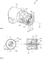
- Figure 3 shows a partly mounted turbine 115 with magnetic brake 225 elements in a first position.
- the magnets 230 lie in first positions radially close to the shaft 220 and close to the axis of rotation 205.
- the centre gearwheel 260 may have cut-outs to allow the magnets 230 to move radially further in. The cut-outs may be in places that do not get in contact with teeth of the levers 250 if the magnets 230 are moved from first to second positions. This may be especially easily done if the number of magnets is two and a radius of the centre gearwheel 260 approximately matches a length of a lever 250.
- Figure 4 shows an axial view (to the left) and a longitudinal section (to the right) of a turbine 115 with magnetic brake 225 elements in the first position.
- the lid 285 is removed so that the magnets 230 can be seen through a centre opening of the annulus shaped element 235.
- the magnets 230 lie in the above-mentioned cut-outs in the gearwheel 260.
- the longitudinal section goes through a plane denoted A-A in the axial view.
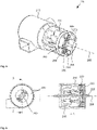
- Figure 5 shows a partly mounted turbine 115 with magnetic brake 225 elements in a second position.
- Figure 5 corresponds to figure 3 apart from the position of the magnetic brake 225 elements.
- magnets 230 lie in larger radial distances to the axis of rotation 205 than in the first position. If the conductive element 235 is mounted, poles of the magnets 230 lie in close axial proximity to the conductive material of the element 235.
- cut-outs in the centre gearwheel 260 do not limit movability of the levers 250 and allow their teeth to keep intermeshing with the gearwheel 260.
- Figure 6 shows an axial view (to the left) and a longitudinal section (to the right) of a turbine 115 with magnetic brake 225 elements in a second position.
- Figure 6 corresponds to figure 4 save the position of the magnets 230.
- the magnets 230 in the second position lie in close axial proximity to the conductive element 235. Their radial distance to the axis of rotation 205 is much larger than in the first position.
- the mechanism 240 is inside a bell like structure which may be formed at the turbine 115 so that the magnets 230 are radially enclosed by a rim or a cylindric wall.
Landscapes
- Engineering & Computer Science (AREA)
- Mechanical Engineering (AREA)
- Magnetic Bearings And Hydrostatic Bearings (AREA)
- Dynamo-Electric Clutches, Dynamo-Electric Brakes (AREA)
Abstract
Description
- Present invention concerns a turbo bristle roller for a vacuum cleaner. More specifically, present invention concerns regulating the speed of said bristle roller.
- A vacuum cleaner comprises a vacuum generator, a filter arrangement and a mouthpiece. The mouthpiece is adapted to be moved over a surface that is to be cleaned. The filter arrangement is usually disposed upstream the generator and adapted to hold back particles like dust that travel with the air sucked in through the mouthpiece.
- In order to disengage particles from the surface, a rotating brush or bristle roller may be provided close to the mouth piece. The roller is rotated around a predetermined axis of rotation, so that the bristles brush over the surface. For powering the roller, a turbine may be disposed in the stream of air through the mouthpiece and provide a rotating motion for the bristle roller. As air speed through the mouthpiece may vary considerably during use of the cleaner, rotating speed of the turbine must be controlled in order to prevent damage on the roller or the surface.
-
DE 195 07 528 A1 proposes to monitor the rotational speed of a turbo-powered bristle roller and reduce a driving torque when the speed exceeds a predetermined threshold. The driving torque may be controlled by allowing a stream of atmospheric air into the turbine, thereby reducing a pressure difference between its sides. This may require user intervention or equipping the mouthpiece part with an air valve for the stream of control air. Operating the valve may require some logic and an electric power supply from the vacuum generator, which makes the cleaner more complex. -
JP 3 261 910 B2 - It is an object of present invention to provide an improved technique for limiting the rotational speed of a turbine for powering a brush roller for a vacuum cleaner. The invention solves the object through the subject matter of the independent claims. Dependent claims describe preferred embodiments.
- A turbo nozzle for a vacuum cleaner comprises a brush roller and a turbine for setting the roller in rotational motion. The turbine is adapted to be traversed by a stream of air travelling through the nozzle. The nozzle further comprises a magnetic brake for limiting rotational speed of the roller, wherein the magnetic brake comprises a permanent magnet affixed to a rotating part of the turbine or the roller, and a conductive element affixed to a stationary part of the nozzle. This way, the moving magnet may cause an eddy current in the conductive element which counteracts rising revolution speeds of the rotating part.
- The eddy current may cause a magnetic force between the magnet and the conductive element so that the moveable part may be effectively braked. Advantageously the braking force may be proportional to a rotational speed of the rotating part so that little or no braking takes place when rotational speeds are low. Braking forces may also be dependent on a distance between the magnet and the conductive element so that a desired braking force may be achieved through dimensioning and relative positioning of the elements. The magnetic brake may operate without mechanical friction so that wear may be very low, making possible reliable operation over extended periods of operation. The magnetic brake may be adapted to prevent exceeding revolution speeds of the turbine and/or brush. Damage caused by an overly fast spinning brush on a surface to be cleaned with the nozzle may be prevented. The magnetic brake may be self-contained and require no electric control means and no electric power supply.
- The turbine may also comprise a centrifugal displacement mechanism that is adapted to move the magnet towards the conductive element in answer to centrifugal forces acting upon the magnet. In other words, the magnet may be moved closer to the magnet as the rotational speed of the turbine or the brush rises. Over decreasing distance, magnetic forces between the magnet and the conductive element may be increased so that the braking force is also increased. A cut-off rotational speed may therefore be more clearly defined. This may aid to increase reactivity of the magnetic brake to varying air speeds acting on the turbine.
- Said displacement mechanism may comprise an elastic element counteracting the centrifugal forces on the magnet. The magnet may be moved back to an inner radial position as the rotational speed decreases so that the braking forces may also be decreased. Effectively, rotational speed of the turbine may be kept as high as possible without exceeding said predetermined threshold. The turbine may be kept at an advantageous operating point and the brush may operate effectively.
- Said mechanism may be adapted to restrict movement of said magnet to a rotational plane with respect to said axis of rotation. By preventing axial movement, a required space for the moveable magnet may be reduced. It is to be noted that movement of the magnet is not necessarily restricted to a radial direction. Instead, magnet movement may be limited to any predetermined curve that lies in a rotational plane around the rotating part's axis of rotation.
- In one preferred embodiment, said mechanism comprises a lever with a first end and a second end. The first end is affixed to said magnet and the second end is hinged to the rotating part. An axis of the hinge is preferred to lie parallel to the turbine's axis of rotation, especially in some predetermined distance. Said lever may restrict movement of the magnet to a circle shaped curve in a rotational plane with respect to the rotating part. A length and hinge point of the lever may be chosen such that a predetermined cut-off speed is realized. A radial distance between the hinge and the axis of rotation may be varied to adapt the brake to a desired cut-off speed. The lever arrangement may be compact in size and sturdy to firmly hold said magnet. By using the lever, the magnet may be kept in the second position by means of centrifugal forces, making an end stop to the lever or magnet unnecessary. Longevity of the mechanism may be increased.
- Said conductive element may be annulus shaped and disposed on an axial side of the magnet, with respect to said axis of rotation. In mathematics, an annulus is a ring-shaped object, a region bounded by two concentric circles. Practically, the conductive element will also have a predetermined axial thickness. The magnet may lie in an inner, open section of the annulus when in a radially inner position, and adjacent to the conductive element when in a radially outer position. A contrast between acting forces between the conductive element and the magnet may be greater than in an arrangement where the conductive element lies radially outwards the magnet.
- It is especially preferred that a magnetic orientation of the magnet is parallel to said axis of rotation. The magnetic orientation may be understood as a line going through a magnetic north pole and a magnetic south pole of the magnet. In a pole section of the magnet, magnetic forces may be maximal, so that the conductive element may be most effective when placed close to a pole. In combination with the annulus-shaped conductive element in an axial position from the magnet, maximum magnetic engagement may be achieved when the magnet is in an outer radial position, and maximum magnetic disengagement (or minimum magnetic engagement) when the magnet is in an inner radial position.
- Said mechanism may be adapted to move said magnet between a first position in which the magnet is substantially disengaged from the conductive element and a second position in which the magnet is engaged with the conductive element. The first position may correspond to an inner radial position and the second to an outer radial position. The magnet may assume the second position if its rotational speed around the rotating part's axis of rotation exceeds a predetermined threshold. The magnet may be pulled back into the first position when the rotational speed drops under a second predetermined threshold.
- It is furthermore preferred that the magnetic brake comprises several magnets which are evenly distributed on a circumference around the axis of rotation and that said mechanism is adapted to synchronize movements of the magnets. By using more than one magnet, effective braking forces may be increased. The mechanism may especially synchronize radial distances of the magnets from the axis of rotation, respectively. Circumferential distances between neighbouring magnets may be kept the same. A heavy spot on the rotating part may be prevented. The rotating part may be balanced, independent of the radial positions the magnets assume. The centre of mass of the constellation may be kept aligned with the axis of rotation.
- The mechanism may especially be adapted to keep the magnets on identical radial distances to the axis of rotation. The magnets are preferred to have identical effective masses. The mechanism may also keep relative distances of neighbouring magnets along the circumference identical.
- In one preferred embodiment, said mechanism comprises a set of gearwheels that intermesh with one gearwheel coaxial to the axis of rotation. A magnet may be affixed to each of the outer gearwheels so that the magnets' radial positions and their relative positions along a circumference to said axis of rotation are synchronized. The magnets may additionally be guided in motion links that extend along circumferences of outer gearwheels' axis of rotation.
- According to another aspect of present invention, a vacuum cleaner comprises a turbo nozzle described herein. The vacuum cleaner may show increased cleaning performance as the brush roller is kept closer to an optimal turning speed.
- The invention will now be described in more detail making reference to the enclosed figures in which:
- Figure 1
- shows a nozzle for a vacuum cleaner;
- Figure 2
- shows an explosion view of a turbine for a nozzle of a vacuum cleaner;
- Figure 3
- shows a partly mounted turbine with magnetic brake elements in a first position;
- Figure 4
- shows an axial view and a longitudinal section of a turbine with magnetic brake elements in a first position;
- Figure 5
- shows a partly mounted turbine with magnetic brake elements in a second position;
- Figure 6
- shows an axial view and a longitudinal section of a turbine with magnetic brake elements in a second position.
-
Figure 1 shows anozzle 100 for avacuum cleaner 105. Thenozzle 100 is adapted to be connected to an air duct leading to thevacuum cleaner 105. The air duct typically comprises a tube or a flexible hollow tube. Abrush roller 110 is provided to mechanically operate on a surface thenozzle 105 is placed upon. Aturbine 115 is provided to set thebrush roller 110 in motion. Theturbine 115 lies in an air duct inside thenozzle 100, the duct opening to the environment on one end and leading to the vacuum cleaner on another end. Air flowing through thenozzle 100 may pass through theturbine 115 on its way to the cleaner 105. -
Figure 2 shows an explosion view of aturbine 115 for anozzle 100 of avacuum cleaner 105. Theturbine 115 comprises an axis ofrotation 205 around which apart 210 is rotatable. In present embodiment, saidpart 210 comprises air blades or vanes that are adapted to catch a stream of air passing through ahousing 215. Thepart 205 may be affixed to ashaft 220 that may be coupled to saidbrush roller 110 to provide a driving torque to set thebrush roller 110 in motion. Thebrush roller 110 may be coupled rotatable, directly or by means of gears or similar, to theshaft 220. - A
magnetic brake 225 is affixed to saidrotating part 210. In a different embodiment, thebrake 225 may also be affixed to a rotating part of thebrush roller 110 or a rotating part of gears or wheels coupling theturbine 115 with thebrush roller 110. For the purposes of explaining present invention, reference will be made to the axis ofrotation 105, which may correspond to anyrotating part 210 coupled to thebrush roller 110 or theturbine 115. - The
magnetic brake 225 comprises twopermanent magnets 230 mounted to therotating part 210 and aconductive element 235 mounted to a fixed part, especially thehousing 215. Amechanism 240 may be provided for moving themagnets 230 between first and second positions. In the first position, amagnet 230 lies close to the axis ofrotation 205 and is magnetically disengaged from theconductive element 235, while in the second position, saidmagnet 230 lies further out in a radial direction with respect to the axis ofrotation 205 and is magnetically engaged with the conductive element. - The
conductive element 235 is preferred to be of the non-magnetic type and may comprise non-magnetic material like aluminium or brass. A ferrous material may also be used. Magnetic engagement occurs when amagnet 230 is moved with respect to theelement 235, so that eddy currents are caused in theelement 235 through magnetic induction. Such electric currents will be transposed into heat almost instantaneously. The energy required to form the eddy currents is taken from the movement of themagnet 230 in close vicinity to theelement 235 so that a braking force between the two elements is generated. The braking force may be dependent on the relative speed between themagnet 230 and theconductive element 235, on the strength of the magnetic field of themagnet 230 and the distance betweenmagnet 230 andelement 235. - It is preferred that the
conductive element 235 is annulus shaped and lies in an axial direction from themagnets 230. Dimensions of the annulus are preferred to be chosen such that themagnets 230 lie in the centre opening of the annulus when resting in the first position and adjacent to the body of the annulus when they are in the second position. Amagnet 230 may have amagnetic orientation 245 that is defined as a line going through North and South poles of a magnet. Theorientation 245 is preferred to lie parallel to the axis ofrotation 205, so that a pole of themagnet 240 is as close as possible to conductive material of theelement 235 when themagnet 240 is in the second position. - The
mechanism 240 guiding themagnets 240 between the first and second positions may comprise alever 250 for eachmagnet 240. Thelever 250 has a first end that is connected to themagnet 230 and a second end that is hinged to therotatable part 210. For hinging, anaxis 255 may be provided on therotatable part 210. Theaxis 255 is preferred to extend parallel to the axis ofrotation 205. In present embodiment, a radial distance of theaxis 255 from the axis ofrotation 205 may be roughly half the distance between first and second positions of amagnet 230. Theaxis 255 may be spaced evenly on a circumference around the axis ofrotation 205. Lengths of thelevers 250 and radial distances of theaxis 250 from the axis ofrotation 205 are preferred to be equal. Likewise, themagnets 230 are preferred to be equal in size, shape and mass. Magnetic strengths of themagnets 230 may also be comparable. Themagnets 230 may comprise a metal or rare earth, like neodymium, so that magnetic forces may be high. - The
levers 255 may be coupled mechanically through gears. In present embodiment, eachlever 255 comprises teeth around a circumference of the associatedaxis 255. Onegearwheel 260 is centred on the axis orrotation 205 and its teeth intermesh with the teeth of eachlever 255. Thecentre gearwheel 260 may rotate freely around said axis ofrotation 205 and may be held on theshaft 220. By means of the intermeshing gears, allmagnets 230 are coupled mechanically in such a way that their radial distances to the axis ofrotation 205 will be kept identical and their spacing in a circumferential direction with be equal. Especially, angles between neighbouringmagnets 230 with respect to the axis ofrotation 205 may be kept at a predetermined value. Anelastic element 265 may be provided to push, pull or swivel themagnets 230 radially inwards to the first position. Apin 270 may be provided on therotating element 210 for theelastic element 265 to hook into. Theelastic element 265 may act upon alever 250 or on thecentre gearwheel 260. In present embodiment, oneelastic element 265 is associated to eachlever 250. - An
optional disc 275 may be placed axially between themagnets 230 and theconductive element 235. Thedisc 275 may have cut-outs 280 in which themagnets 230 may lie. The cut-outs 280 may be shaped such that the magnets may move between first and second positions. In one embodiment, a cut-out 280 may guide an associatedmagnet 230 in its movement in a plane perpendicular to said axis ofrotation 205, thus forming a motion link for themagnet 230. - A
lid 285 may be provided to close thehousing 215 on one axial end so that therotating element 210 and themechanism 225 are accommodated inside thehousing 225. -
Figure 3 shows a partly mountedturbine 115 withmagnetic brake 225 elements in a first position. Pushed inward by the elastic elements, 265, themagnets 230 lie in first positions radially close to theshaft 220 and close to the axis ofrotation 205. Thecentre gearwheel 260 may have cut-outs to allow themagnets 230 to move radially further in. The cut-outs may be in places that do not get in contact with teeth of thelevers 250 if themagnets 230 are moved from first to second positions. This may be especially easily done if the number of magnets is two and a radius of thecentre gearwheel 260 approximately matches a length of alever 250. -
Figure 4 shows an axial view (to the left) and a longitudinal section (to the right) of aturbine 115 withmagnetic brake 225 elements in the first position. - In the axial view, the
lid 285 is removed so that themagnets 230 can be seen through a centre opening of the annulus shapedelement 235. Themagnets 230 lie in the above-mentioned cut-outs in thegearwheel 260. The longitudinal section goes through a plane denoted A-A in the axial view. -
Figure 5 shows a partly mountedturbine 115 withmagnetic brake 225 elements in a second position.Figure 5 corresponds tofigure 3 apart from the position of themagnetic brake 225 elements. Here,magnets 230 lie in larger radial distances to the axis ofrotation 205 than in the first position. If theconductive element 235 is mounted, poles of themagnets 230 lie in close axial proximity to the conductive material of theelement 235. - It can be seen that cut-outs in the
centre gearwheel 260, in which themagnets 230 may be disposed when resting in the first position, do not limit movability of thelevers 250 and allow their teeth to keep intermeshing with thegearwheel 260. -
Figure 6 shows an axial view (to the left) and a longitudinal section (to the right) of aturbine 115 withmagnetic brake 225 elements in a second position.Figure 6 corresponds tofigure 4 save the position of themagnets 230. Themagnets 230 in the second position lie in close axial proximity to theconductive element 235. Their radial distance to the axis ofrotation 205 is much larger than in the first position. In one embodiment, themechanism 240 is inside a bell like structure which may be formed at theturbine 115 so that themagnets 230 are radially enclosed by a rim or a cylindric wall. -
- 100
- nozzle
- 105
- vacuum cleaner
- 110
- brush roller
- 115
- turbine
- 205
- axis of rotation
- 210
- rotating part
- 215
- housing
- 220
- shaft
- 225
- magnetic brake
- 230
- permanent magnet
- 235
- conductive element
- 240
- mechanism
- 245
- magnetic orientation
- 250
- lever
- 255
- axis
- 260
- gearwheel
- 265
- elastic element
- 270
- pin
- 275
- disc
- 280
- cut-out
- 285
- lid
Claims (10)
- A turbo nozzle (100) for a vacuum cleaner (105), the nozzle (100) comprising a brush roller and a turbine (115) for setting the roller in rotational motion; wherein the turbine (115) is adapted to be traversed by a stream of air travelling through the nozzle (100); the nozzle (100) further comprising a magnetic (230) brake for limiting rotational speed of the roller; wherein the magnetic (230) brake comprises a permanent magnet (230) affixed to a rotating part of the turbine (115) or the roller and a conductive element (235) affixed to a stationary part of the nozzle (100); such that the moving magnet (230) causes an eddy current in the conductive element (235).
- Turbo nozzle (100) according to claim 1, further comprising a centrifugal displacement mechanism (225) that is adapted to move the magnet (230) towards the conductive element (235) in answer to centrifugal forces acting upon the magnet (230).
- Turbo nozzle (100) according to claim 2, wherein said displacement mechanism (225) comprises an elastic element (265) counteracting the centrifugal forces on the magnet (230).
- Turbo nozzle (100) according to one of claims 2 or 3, wherein said mechanism (225) is adapted to restrict movement of said magnet (230) to a rotational plane with respect to said axis of rotation (105).
- Turbo nozzle (100) according to one of claims 2 through 4, wherein said mechanism (225) comprises a lever with a first end and a second end; wherein the first end is affixed to said magnet (230) and the second end is hinged to the rotating part, wherein an axis of the hinge lies parallel to the turbine (115)'s axis of rotation (105).
- Turbo nozzle (100) according to one of the above claims, wherein said conductive element (235) is annulus shaped and disposed at an axial side of the magnet (230), with respect to said axis of rotation (105).
- Turbo nozzle (100) according to claim 6, wherein a magnetic (230) orientation of the magnet (230) is parallel to said axis of rotation (105).
- Turbo nozzle (100) according to one of claims 2 through 7, wherein said mechanism (225) is adapted to move said magnet (230) between a first position in which the magnet (230) is substantially disengaged from the conductive element (235) and a second position in which the magnet (230) is engaged with the conductive element (235).
- Turbo nozzle (100) according to one of claims 2 through 8, wherein several magnets (230) are evenly distributed on a circumference around the axis of rotation (205) and said mechanism (225) is adapted to synchronize movements of the magnets (230).
- Vacuum cleaner (105), comprising a turbo nozzle (100) according to one of the above claims.
Priority Applications (1)
| Application Number | Priority Date | Filing Date | Title |
|---|---|---|---|
| EP21167924.6A EP4074233B1 (en) | 2021-04-12 | 2021-04-12 | Speed controlled bristle roller turbine |
Applications Claiming Priority (1)
| Application Number | Priority Date | Filing Date | Title |
|---|---|---|---|
| EP21167924.6A EP4074233B1 (en) | 2021-04-12 | 2021-04-12 | Speed controlled bristle roller turbine |
Publications (2)
| Publication Number | Publication Date |
|---|---|
| EP4074233A1 true EP4074233A1 (en) | 2022-10-19 |
| EP4074233B1 EP4074233B1 (en) | 2025-08-27 |
Family
ID=75477981
Family Applications (1)
| Application Number | Title | Priority Date | Filing Date |
|---|---|---|---|
| EP21167924.6A Active EP4074233B1 (en) | 2021-04-12 | 2021-04-12 | Speed controlled bristle roller turbine |
Country Status (1)
| Country | Link |
|---|---|
| EP (1) | EP4074233B1 (en) |
Citations (5)
| Publication number | Priority date | Publication date | Assignee | Title |
|---|---|---|---|---|
| DE19507528A1 (en) | 1995-03-03 | 1996-09-05 | Wessel Werk Gmbh | Noise reduction method for suction air-driven turbines in vacuum cleaner cleaning heads |
| JP3261910B2 (en) | 1995-01-09 | 2002-03-04 | 株式会社日立製作所 | Vacuum cleaner and its mouthpiece |
| DE202011106752U1 (en) * | 2011-10-14 | 2011-11-30 | Bito-Lagertechnik Bittmann Gmbh | Brake conveyor roller |
| EP3616582A1 (en) * | 2018-08-28 | 2020-03-04 | BSH Hausgeräte GmbH | Nozzle for a vacuum cleaner |
| RU198420U1 (en) * | 2020-02-12 | 2020-07-06 | Закрытое акционерное общество "Инженерно-технический центр "КРОС" | MAGNETIC BRAKE ROLLER FOR ROLLER GRAVITY CONVEYORS |
-
2021
- 2021-04-12 EP EP21167924.6A patent/EP4074233B1/en active Active
Patent Citations (5)
| Publication number | Priority date | Publication date | Assignee | Title |
|---|---|---|---|---|
| JP3261910B2 (en) | 1995-01-09 | 2002-03-04 | 株式会社日立製作所 | Vacuum cleaner and its mouthpiece |
| DE19507528A1 (en) | 1995-03-03 | 1996-09-05 | Wessel Werk Gmbh | Noise reduction method for suction air-driven turbines in vacuum cleaner cleaning heads |
| DE202011106752U1 (en) * | 2011-10-14 | 2011-11-30 | Bito-Lagertechnik Bittmann Gmbh | Brake conveyor roller |
| EP3616582A1 (en) * | 2018-08-28 | 2020-03-04 | BSH Hausgeräte GmbH | Nozzle for a vacuum cleaner |
| RU198420U1 (en) * | 2020-02-12 | 2020-07-06 | Закрытое акционерное общество "Инженерно-технический центр "КРОС" | MAGNETIC BRAKE ROLLER FOR ROLLER GRAVITY CONVEYORS |
Also Published As
| Publication number | Publication date |
|---|---|
| EP4074233B1 (en) | 2025-08-27 |
Similar Documents
| Publication | Publication Date | Title |
|---|---|---|
| US7741746B2 (en) | Magnetic torque limiter | |
| JP7017577B2 (en) | Electric motors, electric motor systems and power generation systems | |
| EP3408928B1 (en) | Magnetic coupling assembly | |
| JP5645028B2 (en) | Rotating electric machine | |
| CN208364445U (en) | Blower | |
| EP4074233B1 (en) | Speed controlled bristle roller turbine | |
| US20230045743A1 (en) | Magnetic pole piece device, magnetic gear, magnetic geared motor, and magnetic geared generator | |
| US20110049902A1 (en) | Air cooled brushless wind alternator | |
| JP7086299B2 (en) | Wind power generator | |
| CN113482978B (en) | High-stability fan power system | |
| CN110425164A (en) | Direct-current brushless special fan | |
| ES2701052T3 (en) | Reduction of rolling forces in an electric machine | |
| CN113675991B (en) | Electromagnetic friction counteraction transmission auxiliary device | |
| TWI559651B (en) | DC motor inner and outer ring stator structure | |
| CN106163951A (en) | Including motor and the drive system of actuating device | |
| JP2005237128A (en) | Energy conversion mechanism | |
| US20210242734A1 (en) | Rotationally balanced electric motor with air-core strator coils | |
| JPH07107718A (en) | Permanent magnet generator | |
| CN114069966A (en) | Hub motor with heat dissipation device | |
| CN113394951A (en) | Magnetic energy power device | |
| CN209676023U (en) | Ultrahigh speed rotor structure of switching reluctance dynamo | |
| JPH0239169B2 (en) | CHOKOSOKUKAITENFURAIHOIIRUNOENERUGINYUSHUTSURYOKUSOCHI | |
| BRPI0620779A2 (en) | trigger system for turning a cleaning head in a tank | |
| CN116131563B (en) | Ultrahigh-speed permanent magnet magnetic suspension motor resisting unilateral shaft thrust and design method | |
| CN111720347B (en) | Industrial fan based on low-speed large-torque magnetic regulating motor |
Legal Events
| Date | Code | Title | Description |
|---|---|---|---|
| PUAI | Public reference made under article 153(3) epc to a published international application that has entered the european phase |
Free format text: ORIGINAL CODE: 0009012 |
|
| STAA | Information on the status of an ep patent application or granted ep patent |
Free format text: STATUS: THE APPLICATION HAS BEEN PUBLISHED |
|
| AK | Designated contracting states |
Kind code of ref document: A1 Designated state(s): AL AT BE BG CH CY CZ DE DK EE ES FI FR GB GR HR HU IE IS IT LI LT LU LV MC MK MT NL NO PL PT RO RS SE SI SK SM TR |
|
| STAA | Information on the status of an ep patent application or granted ep patent |
Free format text: STATUS: REQUEST FOR EXAMINATION WAS MADE |
|
| 17P | Request for examination filed |
Effective date: 20230419 |
|
| RBV | Designated contracting states (corrected) |
Designated state(s): AL AT BE BG CH CY CZ DE DK EE ES FI FR GB GR HR HU IE IS IT LI LT LU LV MC MK MT NL NO PL PT RO RS SE SI SK SM TR |
|
| GRAP | Despatch of communication of intention to grant a patent |
Free format text: ORIGINAL CODE: EPIDOSNIGR1 |
|
| STAA | Information on the status of an ep patent application or granted ep patent |
Free format text: STATUS: GRANT OF PATENT IS INTENDED |
|
| RIC1 | Information provided on ipc code assigned before grant |
Ipc: A47L 9/28 20060101ALI20250326BHEP Ipc: A47L 9/04 20060101AFI20250326BHEP |
|
| INTG | Intention to grant announced |
Effective date: 20250408 |
|
| GRAS | Grant fee paid |
Free format text: ORIGINAL CODE: EPIDOSNIGR3 |
|
| GRAA | (expected) grant |
Free format text: ORIGINAL CODE: 0009210 |
|
| STAA | Information on the status of an ep patent application or granted ep patent |
Free format text: STATUS: THE PATENT HAS BEEN GRANTED |
|
| AK | Designated contracting states |
Kind code of ref document: B1 Designated state(s): AL AT BE BG CH CY CZ DE DK EE ES FI FR GB GR HR HU IE IS IT LI LT LU LV MC MK MT NL NO PL PT RO RS SE SI SK SM TR |
|
| REG | Reference to a national code |
Ref country code: CH Ref legal event code: EP |
|
| REG | Reference to a national code |
Ref country code: DE Ref legal event code: R096 Ref document number: 602021036982 Country of ref document: DE |
|
| REG | Reference to a national code |
Ref country code: IE Ref legal event code: FG4D |
|
| REG | Reference to a national code |
Ref country code: NL Ref legal event code: MP Effective date: 20250827 |
|
| PG25 | Lapsed in a contracting state [announced via postgrant information from national office to epo] |
Ref country code: IS Free format text: LAPSE BECAUSE OF FAILURE TO SUBMIT A TRANSLATION OF THE DESCRIPTION OR TO PAY THE FEE WITHIN THE PRESCRIBED TIME-LIMIT Effective date: 20251227 |
|
| PG25 | Lapsed in a contracting state [announced via postgrant information from national office to epo] |
Ref country code: NO Free format text: LAPSE BECAUSE OF FAILURE TO SUBMIT A TRANSLATION OF THE DESCRIPTION OR TO PAY THE FEE WITHIN THE PRESCRIBED TIME-LIMIT Effective date: 20251127 |
|
| REG | Reference to a national code |
Ref country code: LT Ref legal event code: MG9D |
|
| PG25 | Lapsed in a contracting state [announced via postgrant information from national office to epo] |
Ref country code: PT Free format text: LAPSE BECAUSE OF FAILURE TO SUBMIT A TRANSLATION OF THE DESCRIPTION OR TO PAY THE FEE WITHIN THE PRESCRIBED TIME-LIMIT Effective date: 20251229 |
|
| PG25 | Lapsed in a contracting state [announced via postgrant information from national office to epo] |
Ref country code: FI Free format text: LAPSE BECAUSE OF FAILURE TO SUBMIT A TRANSLATION OF THE DESCRIPTION OR TO PAY THE FEE WITHIN THE PRESCRIBED TIME-LIMIT Effective date: 20250827 |
|
| PG25 | Lapsed in a contracting state [announced via postgrant information from national office to epo] |
Ref country code: HR Free format text: LAPSE BECAUSE OF FAILURE TO SUBMIT A TRANSLATION OF THE DESCRIPTION OR TO PAY THE FEE WITHIN THE PRESCRIBED TIME-LIMIT Effective date: 20250827 Ref country code: NL Free format text: LAPSE BECAUSE OF FAILURE TO SUBMIT A TRANSLATION OF THE DESCRIPTION OR TO PAY THE FEE WITHIN THE PRESCRIBED TIME-LIMIT Effective date: 20250827 |
|
| PG25 | Lapsed in a contracting state [announced via postgrant information from national office to epo] |
Ref country code: GR Free format text: LAPSE BECAUSE OF FAILURE TO SUBMIT A TRANSLATION OF THE DESCRIPTION OR TO PAY THE FEE WITHIN THE PRESCRIBED TIME-LIMIT Effective date: 20251128 |
|
| PG25 | Lapsed in a contracting state [announced via postgrant information from national office to epo] |
Ref country code: SE Free format text: LAPSE BECAUSE OF FAILURE TO SUBMIT A TRANSLATION OF THE DESCRIPTION OR TO PAY THE FEE WITHIN THE PRESCRIBED TIME-LIMIT Effective date: 20250827 |
|
| PG25 | Lapsed in a contracting state [announced via postgrant information from national office to epo] |
Ref country code: LV Free format text: LAPSE BECAUSE OF FAILURE TO SUBMIT A TRANSLATION OF THE DESCRIPTION OR TO PAY THE FEE WITHIN THE PRESCRIBED TIME-LIMIT Effective date: 20250827 |
|
| PG25 | Lapsed in a contracting state [announced via postgrant information from national office to epo] |
Ref country code: PL Free format text: LAPSE BECAUSE OF FAILURE TO SUBMIT A TRANSLATION OF THE DESCRIPTION OR TO PAY THE FEE WITHIN THE PRESCRIBED TIME-LIMIT Effective date: 20250827 Ref country code: BG Free format text: LAPSE BECAUSE OF FAILURE TO SUBMIT A TRANSLATION OF THE DESCRIPTION OR TO PAY THE FEE WITHIN THE PRESCRIBED TIME-LIMIT Effective date: 20250827 |
|
| PG25 | Lapsed in a contracting state [announced via postgrant information from national office to epo] |
Ref country code: RS Free format text: LAPSE BECAUSE OF FAILURE TO SUBMIT A TRANSLATION OF THE DESCRIPTION OR TO PAY THE FEE WITHIN THE PRESCRIBED TIME-LIMIT Effective date: 20251127 |
|
| PG25 | Lapsed in a contracting state [announced via postgrant information from national office to epo] |
Ref country code: ES Free format text: LAPSE BECAUSE OF FAILURE TO SUBMIT A TRANSLATION OF THE DESCRIPTION OR TO PAY THE FEE WITHIN THE PRESCRIBED TIME-LIMIT Effective date: 20250827 |
|
| REG | Reference to a national code |
Ref country code: AT Ref legal event code: MK05 Ref document number: 1828972 Country of ref document: AT Kind code of ref document: T Effective date: 20250827 |
|
| PG25 | Lapsed in a contracting state [announced via postgrant information from national office to epo] |
Ref country code: SM Free format text: LAPSE BECAUSE OF FAILURE TO SUBMIT A TRANSLATION OF THE DESCRIPTION OR TO PAY THE FEE WITHIN THE PRESCRIBED TIME-LIMIT Effective date: 20250827 |
|
| PGFP | Annual fee paid to national office [announced via postgrant information from national office to epo] |
Ref country code: GB Payment date: 20260324 Year of fee payment: 6 |
|
| PG25 | Lapsed in a contracting state [announced via postgrant information from national office to epo] |
Ref country code: DK Free format text: LAPSE BECAUSE OF FAILURE TO SUBMIT A TRANSLATION OF THE DESCRIPTION OR TO PAY THE FEE WITHIN THE PRESCRIBED TIME-LIMIT Effective date: 20250827 |
|
| PG25 | Lapsed in a contracting state [announced via postgrant information from national office to epo] |
Ref country code: AT Free format text: LAPSE BECAUSE OF FAILURE TO SUBMIT A TRANSLATION OF THE DESCRIPTION OR TO PAY THE FEE WITHIN THE PRESCRIBED TIME-LIMIT Effective date: 20250827 |
|
| PG25 | Lapsed in a contracting state [announced via postgrant information from national office to epo] |
Ref country code: IT Free format text: LAPSE BECAUSE OF FAILURE TO SUBMIT A TRANSLATION OF THE DESCRIPTION OR TO PAY THE FEE WITHIN THE PRESCRIBED TIME-LIMIT Effective date: 20250827 |
|
| PG25 | Lapsed in a contracting state [announced via postgrant information from national office to epo] |
Ref country code: CZ Free format text: LAPSE BECAUSE OF FAILURE TO SUBMIT A TRANSLATION OF THE DESCRIPTION OR TO PAY THE FEE WITHIN THE PRESCRIBED TIME-LIMIT Effective date: 20250827 |
|
| PG25 | Lapsed in a contracting state [announced via postgrant information from national office to epo] |
Ref country code: SK Free format text: LAPSE BECAUSE OF FAILURE TO SUBMIT A TRANSLATION OF THE DESCRIPTION OR TO PAY THE FEE WITHIN THE PRESCRIBED TIME-LIMIT Effective date: 20250827 Ref country code: EE Free format text: LAPSE BECAUSE OF FAILURE TO SUBMIT A TRANSLATION OF THE DESCRIPTION OR TO PAY THE FEE WITHIN THE PRESCRIBED TIME-LIMIT Effective date: 20250827 |