EP4074180A1 - A mechanical structure, a method for installing cover plates of a pasta machine, and a pasta machine - Google Patents
A mechanical structure, a method for installing cover plates of a pasta machine, and a pasta machine Download PDFInfo
- Publication number
- EP4074180A1 EP4074180A1 EP21209980.8A EP21209980A EP4074180A1 EP 4074180 A1 EP4074180 A1 EP 4074180A1 EP 21209980 A EP21209980 A EP 21209980A EP 4074180 A1 EP4074180 A1 EP 4074180A1
- Authority
- EP
- European Patent Office
- Prior art keywords
- brackets
- cover plates
- pasta machine
- pasta
- positioning block
- Prior art date
- Legal status (The legal status is an assumption and is not a legal conclusion. Google has not performed a legal analysis and makes no representation as to the accuracy of the status listed.)
- Granted
Links
Images


Classifications
-
- A—HUMAN NECESSITIES
- A21—BAKING; EDIBLE DOUGHS
- A21C—MACHINES OR EQUIPMENT FOR MAKING OR PROCESSING DOUGHS; HANDLING BAKED ARTICLES MADE FROM DOUGH
- A21C3/00—Machines or apparatus for shaping batches of dough before subdivision
- A21C3/02—Dough-sheeters; Rolling-machines; Rolling-pins
-
- A—HUMAN NECESSITIES
- A21—BAKING; EDIBLE DOUGHS
- A21C—MACHINES OR EQUIPMENT FOR MAKING OR PROCESSING DOUGHS; HANDLING BAKED ARTICLES MADE FROM DOUGH
- A21C11/00—Other machines for forming the dough into its final shape before cooking or baking
- A21C11/10—Other machines for forming the dough into its final shape before cooking or baking combined with cutting apparatus
-
- A—HUMAN NECESSITIES
- A21—BAKING; EDIBLE DOUGHS
- A21C—MACHINES OR EQUIPMENT FOR MAKING OR PROCESSING DOUGHS; HANDLING BAKED ARTICLES MADE FROM DOUGH
- A21C11/00—Other machines for forming the dough into its final shape before cooking or baking
- A21C11/16—Extruding machines
-
- A—HUMAN NECESSITIES
- A21—BAKING; EDIBLE DOUGHS
- A21C—MACHINES OR EQUIPMENT FOR MAKING OR PROCESSING DOUGHS; HANDLING BAKED ARTICLES MADE FROM DOUGH
- A21C11/00—Other machines for forming the dough into its final shape before cooking or baking
- A21C11/22—Apparatus with rollers and cutting discs or blades for shaping noodles
Definitions
- the present invention relates to a mechanical structure (also known as mounting structure) for installing cover plates of a pasta making machine, a method for installing the brackets and the said cover plates of the pasta machine, and a pasta machine.
- pasta machine as used here in the present application broadly refers to pasta machines, pasta making machines, pasta makers and noodle making machines, noodle makers or pasta slices making machines and pasta strips making machines and so on, because in general the term pasta broadly refers to various pasta types, for example, pasta slices, pasta strips, noodles and so on.
- a pasta machine is a machine that adopts the principle of parallel rolling, i.e. feeding a dough between two dough rollers or two dough knives rolling parallel to each other; after the dough passing through the dough rollers or dough knives, the dough is rolled into thin slice/thin sheet by the dough rollers or cut into pastas strips like noodles by the pasta knives with key grooves.
- the hand cranked pasta machine was first invented by Angelo De Vito in 1905 in the USA, and then the US patent US 812,704 was granted to him. Afterwards, the pasta machine was improved by an Italian manufacturer, providing a mass manufacture pasta machine for households and kitchens and help people making pasta by machine instead of by hand.
- Conventional pasta machines usually comprise two parts, i.e. the pasta dough rolling part and the cutting part, which are also known as pasta dough roller and pasta dough cutter.
- the conventional pasta machines in order to improve the aesthetics of the pasta machine and protect the internal structure of the machine, usually comprises mainly front cover plates, side cover plates, side brackets, bottom plate, dough rollers or knives, built-in supports and other structures, moreover, at least four to eight pins are arranged/formed on the two end of the each cover plates, and a plurality of assembling holes (slots) are provided on the opposite of the side brackets.
- the problem underlying the present invention was to provide a mechanical structure (also known as mounting structure) for installing cover plates of a pasta machine, which avoid the disadvantages of conventional pasta machines of the art.
- the other object of the present invention is to provide a method for applying and installing the structured cover plates of the pasta machine, which adopts the above-mentioned mechanical structure.
- the method for applying and installing the cover plates of the pasta machine comprises the following steps:
- the further object of the present invention is to provide a pasta machine.
- the pasta machine comprises a main body of pasta machine and the mechanical structure according to the invention, wherein each of the brackets are detachably and respectively connected to both sides of the main body of pasta machine.
- the present invention provides a mechanical structure which includes at least two brackets symmetrically arranging on both sides of pasta machine respectively, and cover plates integrally formed, preferably by sheet metal technology.
- the cover plates are snapped and/or a slid on the brackets.
- the mechanical structure provided by the present invention is well-structured to realize safe and easy installation of cover plates on pasta machine, also it can work as stiffening structure helping to mitigate negative force of the unstable position on pasta machine caused by parallelogram structure.
- the connection between cover plates and the brackets reduces the occurrence of accidents such as improper installation, scratching on the pasta machine, and scratching on the assembly personnel due to the greater difficulties of installation.
- the mechanical structure with the brackets and cover plates, the installation method provided by the present application overcomes the disadvantages of time-consuming, labor-intensive, and hazardous handling occurring in prior art. Moreover, the mechanical structure with cover plates and brackets is also proved to be effective in reducing negative force generate from unstable positions of parallelogram structured pasta machine.
- Preferred embodiments of the mechanic structure according to the invention are those mechanic structures, wherein:
- Figs. 1-4 show the brackets of the mechanical structure (also known as mounting structure) provided by an embodiment of the present invention and how the cover plates connect to the brackets.
- Fig. 7 shows the perspective view of the overall bracket composed of the lower half of the bracket in Fig. 2 and the upper half of the bracket in Fig. 4 .
- a mechanical structure for applying and installing cover plates of a pasta machine comprises:
- the cover plates 2 are integrally formed preferably through sheet metal technology
- the cover plates 2 are detachably connected to the two brackets.
- sheet metal technology as used herein relates to an industrial process to form metal into thin, flat pieces.
- Sheet metal is one of the fundamental forms used in metalworking, and it can be cut and bent into a variety of shapes.
- Preferred metals are aluminum, brass, stainless steel, tin, nickel and titanium.
- the processes for forming sheet metal include bending, curling, decambering, deep drawing, expanding, hemming and seaming, hydroforming, incremental sheet forming (ISF), ironing, laser cutting, photochemical machining, perforating, press brake forming, punching, roll forming, rolling, spinning, stamping, water jet cutting, and wheeling.
- ISF incremental sheet forming
- the two brackets 1 are symmetrically arranged on both sides of the main body of the pasta machine; the cover plates 2 are integrally formed through sheet metal technology, and then the cover plates 2 are assembled between the symmetrically arranged brackets 1 through snapping-on or/and sliding-on.
- the present invention has a direct viewing structure and can be easily assembled. It can also reduce the installation failures and avoid hazardous handling caused by the prior art, for example, improper installation, cover plates and its pins deform, scratching to the brackets and occupational and operational risks of wounding hands. The whole of installation process saves time and effort.
- the installation structure can also support the main body of the pasta machine after installation, so that the main body of the machine will be highly supportive to cope with the deformation caused by force of resistance from operation of rolling pasta machine.
- plurality of positioning blocks is symmetrically provided on the opposite side of the symmetrically arranged brackets 1.
- the positioning blocks include a first positioning block 8 and a second positioning block 9 for fixing the cover plates between the brackets.
- the first positioning block 8 and the second positioning block 9 are respectively connected to the cover plates through two locking members 11 formed on the cover plates, the first positioning block 8 and the second positioning block 9 are preferably processed on the bracket 1 by a stamping process.
- the first positioning block 8 and the second positioning block 9 can be implemented in various shapes accordingly, however, they are preferably rectangular in this embodiment.
- the positioning blocks can further include a third positioning block 10 for properly positioning the cover plate on the brackets.
- the positioning block 10 is provided on the brackets in between the first positioning block 8 and the second positioning block 8, please referring Fig.2 and Fig.4 .
- the positioning block 10 is used to position the cover plate 2 with a special shape, so as to make the cover plate 2 strongly connect to the first positioning block 8 and the second positioning block 9.
- the positioning block 10 in above mentioned embodiment is preferably formed on the brackets 1 through a stamping process.
- the cover plate 2 shall be formed into a special shape conforming to the shape of the pasta machine accordingly, and then the special-shaped part of the cover plates 2 is positioned by the positioning block 10, so that the cover plates 2 will not be easily deformed under pressure, and will be connected to the first positioning block 8 and the second positioning block 9 strongly.
- Fig. 5 is a perspective view of an embodiment of the locking members of the present invention.
- a cover plate 2 includes a main body of the cover plate and two locking members 11 respectively formed on both long sides of the cover plate by a sheet metal process.
- the locking members 11 are not only formed for connecting the bracket 1, but also for avoiding a scratching or a cutting caused by the sharp edge of the cover plate to the assembly personnel during the installation of the mechanical structure; furthermore, the locking members 11 can also act as stiffening ribs of the cover plates 2, so that the cover plates 2 are not easily deformed during the installation and using.
- the locking members 11 are formed as bended-edges on both long-sides of the cover plate 2 respectively by a bending sheet metal process.
- the shape of the locking members 11 in the embodiment is preferably formed as an "L" shape through bending the edges of the pre-cut metal plate.
- the right-angled sides (the bended edge) of the locking members 11 match the first positioning block 8 and the second positioning block 9. With the assistance of external force, the locking members 11 are assembled to the first positioning block 8 and the second positioning block 9 through a snapping-on and/or sliding-on.
- Figs. 6A-6E show the embodiments of the cover plates with the locking members of the present invention.
- the main body of the cover plate located between the two sets of locking members 11, and after the bending sheet metal process of the locking members, the main body is formed by a further sheet metal process according to the outer contour shape of the main body of pasta machine.
- the main body of the cover plate can be shaped into a form with cross-section in a triangle, an arc, etc.. It is determined according to the outer contour shape of the pasta machine covered by the cover plate 2.
- the cover plate 2 formed by the sheet metal process is connected to the bracket 1, and then the special-shaped region of the cover plate 2 is supported and positioned by the third positioning block 10, so that the cover plate 2 are firmly connected to the bracket 1.
- Fig. 8 is a perspective view of the pasta machine provided by an embodiment of the present invention.
- the distance between the symmetrically arranged brackets 1 is preferably equal to the length of the cover plates 2, so that besides covering the main body of the pasta machine, the cover plates 2 can further provide a supporting force on the two brackets 1. Therefore, the brackets 1, the cover plates 2 and the main body of the pasta machine will not be easily deformed by the resistance force generated by the main body of the pasta machine during operation.
- the present invention also provides a method for applying and assembling cover plates of a pasta machine.
- the method for assembling cover plates to a pasta machine includes the following steps: using the above-mentioned mechanical structure and connecting the brackets 1 to the both sides of the pasta machine respectively; shaping the cover plates 2 according to the outer contour of the main body of the pasta machine through sheet metal technology; connecting both ends of the cover plates 2 on the brackets 1 respectively through the said blocks.
- the steps of the method for assembling the cover plates and main body of the pasta machine further includes:
- the above-mentioned method of connecting the cover plates 2 to the brackets 1 includes: firstly connecting one long-side of the cover plate 2 to one set of positioning blocks of both two brackets 1 through the locking members 11 thereon, and then rotating the cover plate till the other long-side of the cover plate 2 is snapped on the other set of positioning blocks of both brackets 1 through the locking members 11 on the other long-side.
- Figs. 1-2 Preferably, as showed in Figs. 1-2 , firstly connecting the two brackets 1 to both sides of the pasta machine, and snapping the locking member 11 of one long-side of the cover plate 2 on one set of blocks formed on the two brackets 1, for example, the set of first positioning blocks 9; and then rotating the whole cover plate till the locking member 11 of the other side of the cover plate 2 snaps on the other set of blocks formed on the two brackets, for example the set of second positioning blocks 10 , so that the cover plate 2 is connected to blocks through snapping-on.
- the installation process is completed.
- the above-mentioned method of connecting the cover plates 2 to the brackets 1 includes: firstly connecting both locking members 11 of the cover plate 2 to the brackets 1 arranged on both sides of the pasta machine, and then pushing the cover plate 2 directly till all the position blocks slide under the locking member 11.
- Fig. 8 is a perspective view of the pasta machine provided by an embodiment of the present invention.
- the pasta machine includes a main body of pasta machine and the above-mentioned mechanical structure. Both sides of the main body of the pasta machine are detachably connected with brackets 1.
- the main body of the pasta machine further includes a base 3; the base 3 is arranged on one side of the cover plates 2 and used for supporting the pasta machine; a plurality of driving rollers 5 are arranged between the base 3 and the cover plate 2, and rotate synchronously.
- the two brackets 1 are symmetrically arranged at the two ends of the driving roller 5 respectively, and protected by housings 6 respectively; one end of the driving roller 5 is connected to a driving source 7, and further more connected to the power output end of the driving source 7; a discharge outlet 12 is also provided between the driving roller 5 and the base 3; an adjustment member 4 is provided at one end of the discharge outlet 12 for adjusting the thickness of the pasta products.
- the driving member 7 provides power to drive the driving roller 5 to rotate, so that the plurality of driving rollers 5 squeeze and cut the dough, and then output the pasta products through the discharge outlet 12.
- the size for example, the thickness and the length
- the outputted pasta products can be adjusted through the adjustment member 4.
- the driving member 7 can be a crank, a motor, etc., however, a hand crank is preferably used here.
- the driving member 7 provides power to drive the driving roller 5 to rotate.
- the plurality of driving rollers 5 are provided and are connected to each other by gears and/or conveyor belts, so as to work together properly to process the dough into dough plate, and then the dough plate is further processed to pasta products, for example pasta strips or pasta slices. The process of making pasta products is completed.
- the adjustment member 4 is provided to adjust the distance between the driving rollers 5, and further adjust the size (the thickness and the length) of the outputted pasta products from the discharge outlet 12.
- the above-described embodiments of the present invention provide a mechanical structure and based on the mechanical structure, a method for assembling cover plates to the main body of a pasta machine and a pasta machine are provided.
- two brackets 1 are symmetrically arranged on both sides of pasta machine respectively, and the cover plates 2 are integrally formed by sheet metal technology.
- the cover plates are then assembled and connected to the brackets 1 through the position blocks and the assembling method of snapping-on and/or sliding-on.
- the mechanical structure provided by the present invention is well-structured to realize safe and easy installation of cover plates on pasta machine.
- the connection between cover plates and the brackets reduces the occurrence of failures and accidents such as improper installation, scratching of the pasta machine, and scratching of the construction personnel due to the greater difficulties of installation.
- the locking member in L shape (bended edge) on both long sides of the cover plates resolve hazardous handling problems of prior art, which help to avoid wounding assembly personnel during installation process and eliminate contacting injuries to final users when using pasta machine.
- the mechanical structure provided by the present application overcomes the disadvantages of time-consuming and labor-intensive occurring in prior art, Moreover, the mechanical structure can also support the main body of the pasta making machine after installation, so that the main body of the pasta making machine and the BUILT-IN structure are not easily deformed under the force of resistance.
- connection can be a fixed connection, a detachable connection, or an integral connection. It can also be a mechanical connection or an electrical connection; it can also be a directly connection or an indirect connection through an intermediate medium; and it can be the internal communication between two components.
- connection can be a fixed connection, a detachable connection, or an integral connection. It can also be a mechanical connection or an electrical connection; it can also be a directly connection or an indirect connection through an intermediate medium; and it can be the internal communication between two components.
- connection can be a fixed connection, a detachable connection, or an integral connection. It can also be a mechanical connection or an electrical connection; it can also be a directly connection or an indirect connection through an intermediate medium; and it can be the internal communication between two components.
Landscapes
- Life Sciences & Earth Sciences (AREA)
- Engineering & Computer Science (AREA)
- Food Science & Technology (AREA)
- Noodles (AREA)
- Manufacturing And Processing Devices For Dough (AREA)
- Commercial Cooking Devices (AREA)
Abstract
Description
- The present invention relates to a mechanical structure (also known as mounting structure) for installing cover plates of a pasta making machine, a method for installing the brackets and the said cover plates of the pasta machine, and a pasta machine.
- The term pasta machine as used here in the present application broadly refers to pasta machines, pasta making machines, pasta makers and noodle making machines, noodle makers or pasta slices making machines and pasta strips making machines and so on, because in general the term pasta broadly refers to various pasta types, for example, pasta slices, pasta strips, noodles and so on.
- A pasta machine is a machine that adopts the principle of parallel rolling, i.e. feeding a dough between two dough rollers or two dough knives rolling parallel to each other; after the dough passing through the dough rollers or dough knives, the dough is rolled into thin slice/thin sheet by the dough rollers or cut into pastas strips like noodles by the pasta knives with key grooves. The hand cranked pasta machine was first invented by
Angelo De Vito in 1905 in the USA, and then the US patent US 812,704 was granted to him. Afterwards, the pasta machine was improved by an Italian manufacturer, providing a mass manufacture pasta machine for households and kitchens and help people making pasta by machine instead of by hand. - Conventional pasta machines usually comprise two parts, i.e. the pasta dough rolling part and the cutting part, which are also known as pasta dough roller and pasta dough cutter. In order to improve the aesthetics of the pasta machine and protect the internal structure of the machine, the conventional pasta machines, as shown in
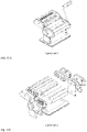
Fig.10A and Fig.10B , usually comprises mainly front cover plates, side cover plates, side brackets, bottom plate, dough rollers or knives, built-in supports and other structures, moreover, at least four to eight pins are arranged/formed on the two end of the each cover plates, and a plurality of assembling holes (slots) are provided on the opposite of the side brackets. - During the installation of the cover plates of the conventional pasta machines, four or eight pins of each cover plate have to be squeezed to the assembling holes reserved on the brackets of the pasta machine. However, it is rather difficult to squeeze all the pins of the cover plates to the assembling holes in a short time, a skilled assembly personnel spends minimum 20 minutes to finish the assembly of the pasta machine with such cover plates. Therefore, the method for assembling the cover plates of the pasta machine in the prior art is unpractical, since it is easy to cause accidents such as improper installation, scratching to the pasta machine, scratching to the assembly personnel, etc. Moreover, the installation process is also time-consuming and labor-intensive, and it causes a greater deformation of the cover plate under the force of resistance in operation of the pasta making machine, even causes the damage of the built-in structure of the pasta making machine.
- The problem underlying the present invention was to provide a mechanical structure (also known as mounting structure) for installing cover plates of a pasta machine, which avoid the disadvantages of conventional pasta machines of the art.
- This problem has been solved according to the present invention by providing a mechanical structure for installing cover plates of the pasta machine, comprising:
- at least two brackets, which are arranged symmetrically on both sides of the pasta machine respectively;
- at least two cover plates, which are arranged between the at least two brackets, wherein both ends of each cover plate are connected to the brackets; wherein
- the cover plates are integrally formed and detachably connected to the at least two brackets.
- The other object of the present invention is to provide a method for applying and installing the structured cover plates of the pasta machine, which adopts the above-mentioned mechanical structure. The method for applying and installing the cover plates of the pasta machine comprises the following steps:
- arranging the brackets symmetrically on both sides of the pasta machine respectively,
- shaping the cover plates into a corresponding form, and
- installing the cover plates between the two brackets through the plurality of blocks on the side of brackets.
- The further object of the present invention is to provide a pasta machine. The pasta machine comprises a main body of pasta machine and the mechanical structure according to the invention, wherein each of the brackets are detachably and respectively connected to both sides of the main body of pasta machine.
- Comparing with the prior art, the technical solutions provided by the present invention have the following advantages: The present invention provides a mechanical structure which includes at least two brackets symmetrically arranging on both sides of pasta machine respectively, and cover plates integrally formed, preferably by sheet metal technology. The cover plates are snapped and/or a slid on the brackets. The mechanical structure provided by the present invention is well-structured to realize safe and easy installation of cover plates on pasta machine, also it can work as stiffening structure helping to mitigate negative force of the unstable position on pasta machine caused by parallelogram structure. The connection between cover plates and the brackets reduces the occurrence of accidents such as improper installation, scratching on the pasta machine, and scratching on the assembly personnel due to the greater difficulties of installation. The mechanical structure with the brackets and cover plates, the installation method provided by the present application overcomes the disadvantages of time-consuming, labor-intensive, and hazardous handling occurring in prior art. Moreover, the mechanical structure with cover plates and brackets is also proved to be effective in reducing negative force generate from unstable positions of parallelogram structured pasta machine.
-
-
FIG. 1 is a perspective view of an embodiment of the lower half of the bracket of the mechanical structure provided by the present invention (with cover plates); -
FIG. 2 is a schematic side view of the lower half of the bracket shown inFig. 1 ; -
FIG. 3 is a perspective view of an embodiment of the upper half of the bracket of the mechanical structure provided by the present invention (with cover plates); -
FIG. 4 is a schematic side view of the upper half of the bracket shown inFig.3 ; -
FIG. 5 is a perspective view of an embodiment of the locking members; -
FIGS. 6A-6E show embodiments of each cover plate with locking members respectively shown in the embodiments ofFigs. 1-4 ; -
FIG. 7 shows the perspective view of the overall bracket composed of the lower half of the bracket inFig. 2 and the upper half of the bracket inFig. 4 ; -
FIG. 8 is a perspective view of the pasta machine provided by an embodiment of the present invention; -
FIG. 9 shows an exploded view of the present application before the cover plates are assembled to the brackets; -
FIG. 10A is a perspective view of a pasta machine according to the prior art; -
FIG. 10B is an exploded view of a pasta machine according to the prior art. - Wherein: 1-bracket (s); 2-cover plate (s); 3-base; 4-adjustment member; 5-driving roller(s); 6-housing; 7-driving source; 8- the first positioning block; 9- the second positioning block; 10- the third positioning block; 11-locking member(s); 12- discharge outlet.
- In order to clarify the objects, technical solutions, and the advantages of the present invention clearly, the description of the present invention in detail with reference to the accompanying drawings and preferred embodiments are provided here in below. It should be understood that the embodiments described here are only used to explain the present invention, but not to limit the scope of the present invention.
- In order to clarify the technical problems to be solved by the present invention, the technical solutions and beneficial effects of the present application clearly, the following content further describes the present invention in detail with reference to the accompanying drawings and preferred embodiments. With the preferred embodiments the present invention can be further understand by those skilled in the art, but the preferred embodiments are not used to limit the present invention in any form. It should be pointed out that for those skilled in the art, several modifications and improvements can be made without departing from the concept of the present invention. These all belong to the protection scope of the present invention. In order to clarify the technical solution of the present invention in a simple way, some well-known structures and some well-known processing steps of installation in the art are omitted here. It should be understood that the same reference number always represent the same member. Furthermore, various members and regions in the drawings are only schematically illustrated and they are not used to limit the relative sizes or intervals of the various parts of present application.
- Preferred embodiments of the mechanic structure according to the invention are those mechanic structures, wherein:
- (A) a plurality of blocks is provided on the opposite sides of the at least two
brackets 1, and the plurality of blocks comprise afirst positioning block 8 and asecond positioning block 9, , wherein thefirst positioning block 8 and thesecond positioning block 9 are used for connecting to thecorresponding cover plate 2. - (B) the blocks further comprise a
third positioning block 10, thethird positioning block 10, which is arranged between thefirst positioning block 8 and thesecond positioning block 9; thethird positioning block 10 is used for positioning and supporting the special shape of the cover plate2. - (C) wherein that, two sets of
locking members 11 are formed integrally on both long-sides of thecover plate 2 respectively through sheet metal technology, and the two sets oflocking members 11 are used for connecting to thebrackets 1. - (D) the
cover plates 2 are shaped into a shape according adapted to the requirements of the outer contour form of the pasta machine. - (E) wherein that the distance between the two symmetrically arranged
brackets 1 is equal to the length of the cover plates. - Preferred embodiments of the method for installing the cover plates of the pasta machine according to the invention are those methods:
- (F) A method according to the invention, which comprises the following steps:
- arranging the
brackets 1 symmetrically on both sides of the pasta machine respectively; - shaping a pre-cut metal plate into the cover plate with a corresponding form through sheet metal technology; and
- installing the
cover plates 2 between the twobrackets 1 through the plurality of blocks.
- arranging the
- (G) A method according to the invention, in which installing the
cover plates 2 between the twobrackets 1 through the plurality of blocks includes the following steps:- connecting one long-side of the
cover plates 2 to one set of positioning blocks of both twobrackets 1 through the lockingmember 11 thereon, and - rotating the cover plates till the other long-side of the
cover plates 2 is connected to the other set of positioning blocks of bothbrackets 1 through the lockingmember 11 on the other long-side; wherein both long-side of the cover plates are edge-bended.
- connecting one long-side of the
- (H) wherein that installing the
cover plates 2 between the twobrackets 1 through the plurality of blocks includes the following steps:- connecting both locking
members 11 of thecover plate 2 to thebrackets 1 arranged on both sides of the pasta machine, and - pushing the
cover plate 2 directly till until all the position blocks slide under the lockingmember 11 and thecover plates 2 are well connected to brackets.
- connecting both locking
- The implementation of the present invention will be described in detail with reference to the preferred embodiments below.
-
Figs. 1-4 show the brackets of the mechanical structure (also known as mounting structure) provided by an embodiment of the present invention and how the cover plates connect to the brackets.Fig. 7 shows the perspective view of the overall bracket composed of the lower half of the bracket inFig. 2 and the upper half of the bracket inFig. 4 . - As
Figs. 1-4 andFig.7 show, a mechanical structure for applying and installing cover plates of a pasta machine comprises: -
brackets 1, at least two brackets are provided, and are arranged symmetrically on both sides of the pasta machine respectively. - cover
plates 2, a plurality of cover plates is provided and arranged between twobrackets 1 for covering and protecting the main body of the pasta machine; both ends of eachcover plate 2 are connected with thebrackets 1; - The
cover plates 2 are integrally formed preferably through sheet metal technology; - The
cover plates 2 are detachably connected to the two brackets. - The term "sheet metal technology" as used herein relates to an industrial process to form metal into thin, flat pieces. Sheet metal is one of the fundamental forms used in metalworking, and it can be cut and bent into a variety of shapes. Preferred metals are aluminum, brass, stainless steel, tin, nickel and titanium. The processes for forming sheet metal include bending, curling, decambering, deep drawing, expanding, hemming and seaming, hydroforming, incremental sheet forming (ISF), ironing, laser cutting, photochemical machining, perforating, press brake forming, punching, roll forming, rolling, spinning, stamping, water jet cutting, and wheeling.
- In the embodiment of the present invention, the two
brackets 1 are symmetrically arranged on both sides of the main body of the pasta machine; thecover plates 2 are integrally formed through sheet metal technology, and then thecover plates 2 are assembled between the symmetrically arrangedbrackets 1 through snapping-on or/and sliding-on. The present invention has a direct viewing structure and can be easily assembled. It can also reduce the installation failures and avoid hazardous handling caused by the prior art, for example, improper installation, cover plates and its pins deform, scratching to the brackets and occupational and operational risks of wounding hands. The whole of installation process saves time and effort. Moreover, the installation structure can also support the main body of the pasta machine after installation, so that the main body of the machine will be highly supportive to cope with the deformation caused by force of resistance from operation of rolling pasta machine. - As shown in the preferred embodiment of the present invention in
Figs 2 ,4 , and7 , plurality of positioning blocks is symmetrically provided on the opposite side of the symmetrically arrangedbrackets 1. The positioning blocks include afirst positioning block 8 and asecond positioning block 9 for fixing the cover plates between the brackets. - The
first positioning block 8 and thesecond positioning block 9 are respectively connected to the cover plates through two lockingmembers 11 formed on the cover plates, thefirst positioning block 8 and thesecond positioning block 9 are preferably processed on thebracket 1 by a stamping process. Thefirst positioning block 8 and thesecond positioning block 9 can be implemented in various shapes accordingly, however, they are preferably rectangular in this embodiment. When thecover plates 1 are connected to thefirst positioning block 8 and thesecond positioning block 9, the sides of thefirst positioning block 8 and thesecond positioning block 9 are respectively buckled together with the lockingmembers 11 formed on thecover plate 2 for forming a supporting force, so that thecover plate 2 is fixed to thebracket 1 and will not easily fall depart frombracket 1. - As shown in
Figs 2 ,4 , and7 , as another preferred embodiment of the present invention, the positioning blocks can further include athird positioning block 10 for properly positioning the cover plate on the brackets. Thepositioning block 10 is provided on the brackets in between thefirst positioning block 8 and thesecond positioning block 8, please referringFig.2 andFig.4 . - Preferably, when the
cover plates 2 are connected to thefirst position block 8 and thesecond position block 9, thepositioning block 10 is used to position thecover plate 2 with a special shape, so as to make thecover plate 2 strongly connect to thefirst positioning block 8 and thesecond positioning block 9. - The
positioning block 10 in above mentioned embodiment is preferably formed on thebrackets 1 through a stamping process. When the region of the pasta machine covered by thecover plate 2 has a special shape, thecover plate 2 shall be formed into a special shape conforming to the shape of the pasta machine accordingly, and then the special-shaped part of thecover plates 2 is positioned by thepositioning block 10, so that thecover plates 2 will not be easily deformed under pressure, and will be connected to thefirst positioning block 8 and thesecond positioning block 9 strongly. -
Fig. 5 is a perspective view of an embodiment of the locking members of the present invention. As showed inFig. 5 , acover plate 2 includes a main body of the cover plate and two lockingmembers 11 respectively formed on both long sides of the cover plate by a sheet metal process. The lockingmembers 11 are not only formed for connecting thebracket 1, but also for avoiding a scratching or a cutting caused by the sharp edge of the cover plate to the assembly personnel during the installation of the mechanical structure; furthermore, the lockingmembers 11 can also act as stiffening ribs of thecover plates 2, so that thecover plates 2 are not easily deformed during the installation and using. - The locking
members 11 are formed as bended-edges on both long-sides of thecover plate 2 respectively by a bending sheet metal process. The shape of the lockingmembers 11 in the embodiment is preferably formed as an "L" shape through bending the edges of the pre-cut metal plate. The right-angled sides (the bended edge) of the lockingmembers 11 match thefirst positioning block 8 and thesecond positioning block 9. With the assistance of external force, the lockingmembers 11 are assembled to thefirst positioning block 8 and thesecond positioning block 9 through a snapping-on and/or sliding-on. -
Figs. 6A-6E show the embodiments of the cover plates with the locking members of the present invention. As showed inFigs. 6A-6E , the main body of the cover plate located between the two sets of lockingmembers 11, and after the bending sheet metal process of the locking members, the main body is formed by a further sheet metal process according to the outer contour shape of the main body of pasta machine. - As showed in
Figs. 6A-6E , the main body of the cover plate can be shaped into a form with cross-section in a triangle, an arc, etc.. It is determined according to the outer contour shape of the pasta machine covered by thecover plate 2. Thecover plate 2 formed by the sheet metal process is connected to thebracket 1, and then the special-shaped region of thecover plate 2 is supported and positioned by thethird positioning block 10, so that thecover plate 2 are firmly connected to thebracket 1. -
Fig. 8 is a perspective view of the pasta machine provided by an embodiment of the present invention. As shown inFig. 8 , the distance between the symmetrically arrangedbrackets 1 is preferably equal to the length of thecover plates 2, so that besides covering the main body of the pasta machine, thecover plates 2 can further provide a supporting force on the twobrackets 1. Therefore, thebrackets 1, thecover plates 2 and the main body of the pasta machine will not be easily deformed by the resistance force generated by the main body of the pasta machine during operation. - As shown in
Figures 1-7 , the present invention also provides a method for applying and assembling cover plates of a pasta machine. The method for assembling cover plates to a pasta machine includes the following steps: using the above-mentioned mechanical structure and connecting thebrackets 1 to the both sides of the pasta machine respectively; shaping thecover plates 2 according to the outer contour of the main body of the pasta machine through sheet metal technology; connecting both ends of thecover plates 2 on thebrackets 1 respectively through the said blocks. - In the preferable implement of the present invention, the steps of the method for assembling the cover plates and main body of the pasta machine further includes:
- Step 1: Bending both long-sides of a pre-cut metal plate into a form with two bended edges at two opposite long-sides through sheet metal technology to form the locking
members 11, wherein, the pre-cut metal plate is used for forming thecover plates 2; - Step 2 : Shaping the edges-blended mental plate into the cover plate according to the outer contour of the main body of the pasta machine;
- Step 3 : Stamping the positioning blocks on the side surface of the
brackets 1 according to the outer contour of the pasta machine main body and the shape of thecover plates 2, so as that the angle and the position of the blocks matches thecover plates 2; - Step 4: Connecting the
cover plates 2 to thebrackets 1. - Further, the above-mentioned method of connecting the
cover plates 2 to thebrackets 1 includes: firstly connecting one long-side of thecover plate 2 to one set of positioning blocks of both twobrackets 1 through the lockingmembers 11 thereon, and then rotating the cover plate till the other long-side of thecover plate 2 is snapped on the other set of positioning blocks of bothbrackets 1 through the lockingmembers 11 on the other long-side. - Preferably, as showed in
Figs. 1-2 , firstly connecting the twobrackets 1 to both sides of the pasta machine, and snapping the lockingmember 11 of one long-side of thecover plate 2 on one set of blocks formed on the twobrackets 1, for example, the set of first positioning blocks 9; and then rotating the whole cover plate till the lockingmember 11 of the other side of thecover plate 2 snaps on the other set of blocks formed on the two brackets, for example the set of second positioning blocks 10 , so that thecover plate 2 is connected to blocks through snapping-on. The installation process is completed. - Further, the above-mentioned method of connecting the
cover plates 2 to thebrackets 1 includes: firstly connecting both lockingmembers 11 of thecover plate 2 to thebrackets 1 arranged on both sides of the pasta machine, and then pushing thecover plate 2 directly till all the position blocks slide under the lockingmember 11. - Preferably, as showed in
Figs. 3-4 , firstly connecting both lockingmembers 11 of thecover plates 2 to all corresponding positioning blocks of both twobrackets 1 through the lockingmember 11 thereon, and then pushing the cover plates till the both lockingmembers 11 of long-side of thecover plates 2 are sliding under all positioning blocks ofbrackets 1, so that thecover plate 2 is well-connected to blocks. The installation process is completed. -
Fig. 8 is a perspective view of the pasta machine provided by an embodiment of the present invention. As shown inFigure 8 , the pasta machine includes a main body of pasta machine and the above-mentioned mechanical structure. Both sides of the main body of the pasta machine are detachably connected withbrackets 1. - Preferably, the main body of the pasta machine further includes a
base 3; thebase 3 is arranged on one side of thecover plates 2 and used for supporting the pasta machine; a plurality of drivingrollers 5 are arranged between thebase 3 and thecover plate 2, and rotate synchronously. The twobrackets 1 are symmetrically arranged at the two ends of the drivingroller 5 respectively, and protected byhousings 6 respectively; one end of the drivingroller 5 is connected to a drivingsource 7, and further more connected to the power output end of the drivingsource 7; adischarge outlet 12 is also provided between the drivingroller 5 and thebase 3; anadjustment member 4 is provided at one end of thedischarge outlet 12 for adjusting the thickness of the pasta products. - The driving
member 7 provides power to drive the drivingroller 5 to rotate, so that the plurality of drivingrollers 5 squeeze and cut the dough, and then output the pasta products through thedischarge outlet 12. During the manufacturing of the pasta products, the size (for example, the thickness and the length) of the outputted pasta products can be adjusted through theadjustment member 4. - The driving
member 7 can be a crank, a motor, etc., however, a hand crank is preferably used here. The drivingmember 7 provides power to drive the drivingroller 5 to rotate. - The plurality of driving
rollers 5 are provided and are connected to each other by gears and/or conveyor belts, so as to work together properly to process the dough into dough plate, and then the dough plate is further processed to pasta products, for example pasta strips or pasta slices. The process of making pasta products is completed. - The
adjustment member 4 is provided to adjust the distance between the drivingrollers 5, and further adjust the size (the thickness and the length) of the outputted pasta products from thedischarge outlet 12. - The above-described embodiments of the present invention provide a mechanical structure and based on the mechanical structure, a method for assembling cover plates to the main body of a pasta machine and a pasta machine are provided. Wherein two
brackets 1 are symmetrically arranged on both sides of pasta machine respectively, and thecover plates 2 are integrally formed by sheet metal technology. The cover plates are then assembled and connected to thebrackets 1 through the position blocks and the assembling method of snapping-on and/or sliding-on. The mechanical structure provided by the present invention is well-structured to realize safe and easy installation of cover plates on pasta machine. The connection between cover plates and the brackets reduces the occurrence of failures and accidents such as improper installation, scratching of the pasta machine, and scratching of the construction personnel due to the greater difficulties of installation. The locking member in L shape (bended edge) on both long sides of the cover plates resolve hazardous handling problems of prior art, which help to avoid wounding assembly personnel during installation process and eliminate contacting injuries to final users when using pasta machine. The mechanical structure provided by the present application overcomes the disadvantages of time-consuming and labor-intensive occurring in prior art, Moreover, the mechanical structure can also support the main body of the pasta making machine after installation, so that the main body of the pasta making machine and the BUILT-IN structure are not easily deformed under the force of resistance. - In the above-described preferred embodiments of the present invention, it should be noted that the terms "installation", "assembly" "connect with/to" and "connection" should be interpreted broadly unless otherwise specified and limited. For example, the connection can be a fixed connection, a detachable connection, or an integral connection. It can also be a mechanical connection or an electrical connection; it can also be a directly connection or an indirect connection through an intermediate medium; and it can be the internal communication between two components. For those skilled in the art, the specific meaning of the above-mentioned terms in the present invention can be understood through specific circumstances.
- The preferred embodiments of the present invention have been described in detail above. However, the present invention is not limited to the above-mentioned embodiments. Those skilled in the art can also make various modifications and improvements to the present invention without any effort without departing from the purpose of the present invention in the scope of their knowledge. It is unnecessary and impossible to list all the implementation methods here. The obvious improvements or modifications derived from the present application and the above-mentioned embodiments are still within the protection scope of the present invention.
Claims (11)
- A mechanical structure, comprising:at least two brackets (1), which are arranged symmetrically on both sides of the pasta machine respectively,at least two cover plates (2), which are arranged between the at least two brackets, and wherein both ends of each cover plate are connected to the brackets, whereinthe cover plates (2) are integrally formed and detachably connected to the at least two brackets.
- The mechanical structure as claimed in claim 1, wherein a plurality of blocks are provided on the opposite sides of the at least two brackets (1), and the plurality of blocks comprise a first positioning block (8) and a second positioning block (9), wherein the first positioning block (8) and the second positioning block (9) are used for connecting to the corresponding cover plate (2).
- The mechanical structure as claimed in claim 2, wherein the blocks further comprise a third positioning block (10), which is arranged between the first positioning block (8) and the second positioning block (9); the third positioning block (10) is used for positioning and supporting the shape of the cover plate (2).
- The mechanical structure as claimed in any one of claims 1 to 3, wherein two sets of locking members (11) are formed integrally on both long sides of the cover plate (2) respectively, and the two sets of locking members (11) are used for connecting to the brackets (1).
- The mechanical structure as claimed in any one of claims 1 to 4, wherein the cover plates (2) exhibit a shape adapted to the requirements of the outer contour form of the pasta machine.
- The mechanical structure as claimed in any one of claims 1 to 5, wherein the distance between the two symmetrically arranged brackets (1) is equal to the length of the cover plates.
- A method for installing the cover plates of the pasta machine, wherein that the mechanical structure as claimed in anyone of claims 1-6 is adopted, and the method for installing the cover plates of the pasta machine comprises the following steps:arranging the brackets (1) symmetrically on both sides of the pasta machine respectively;shaping a pre-cut metal plate into the cover plate with a corresponding form through sheet metal technology; andinstalling the cover plates (2) between the two brackets (1) through the plurality of blocks.
- The method for installing the cover plates of the pasta machine, as claimed in claim 7, wherein that shaping a pre-cut metal plate into the cover plate with a corresponding form includes at least the following steps:shaping a pre-cut metal plate into an edge-bended form with two bended edges respectively at two opposite long-sides as locking members (11); andshaping the edge-bended mental plate into the cover plate with a corresponding form.
- The method for installing the cover plates of the pasta machine, as claimed in claim 7 or 8, wherein installing the cover plates (2) between the two brackets (1) through the plurality of blocks includes the following steps:connecting one long-side of the cover plates (2) to one set of positioning blocks of two brackets (1) through the locking member (11) thereon, androtating the cover plates till the other long-side of the cover plates (2) is connected to the other set of positioning blocks of both brackets (1) through the locking member (11) on the other long-side; wherein both long-side of the cover plates are edge-bended.
- The method for installing the cover plates of the pasta machine, as claimed in any one of claims 7 to 9, wherein installing the cover plates (2) between the two brackets (1) through the plurality of blocks includes the following steps:connecting both locking members (11) of the cover plate (2) to the brackets (1) arranged on both sides of the pasta machine, andpushing the cover plate (2) directly until all the position blocks slide under the locking member (11) and the cover plates (2) are connected to brackets.
- A pasta machine, wherein that the pasta machine comprises a main body of pasta machine and the mechanical structure according to any one of claims 1-6; the brackets (1) are detachably and respectively connected to both sides of the main body of pasta machine.
Applications Claiming Priority (1)
| Application Number | Priority Date | Filing Date | Title |
|---|---|---|---|
| CN202110393821.6A CN112889868A (en) | 2021-04-13 | 2021-04-13 | Mounting structure, assembling method of decorative plate of noodle machine and noodle machine |
Publications (2)
| Publication Number | Publication Date |
|---|---|
| EP4074180A1 true EP4074180A1 (en) | 2022-10-19 |
| EP4074180B1 EP4074180B1 (en) | 2026-03-04 |
Family
ID=76110529
Family Applications (1)
| Application Number | Title | Priority Date | Filing Date |
|---|---|---|---|
| EP21209980.8A Active EP4074180B1 (en) | 2021-04-13 | 2021-11-23 | Method for installing cover plates of a pasta machine, and a pasta machine |
Country Status (3)
| Country | Link |
|---|---|
| US (1) | US11785952B2 (en) |
| EP (1) | EP4074180B1 (en) |
| CN (1) | CN112889868A (en) |
Families Citing this family (1)
| Publication number | Priority date | Publication date | Assignee | Title |
|---|---|---|---|---|
| WO2026020179A1 (en) * | 2024-07-19 | 2026-01-22 | Columbia Insurance Company | Dough roller assembly and method of cleaning same |
Citations (6)
| Publication number | Priority date | Publication date | Assignee | Title |
|---|---|---|---|---|
| US812704A (en) | 1905-05-04 | 1906-02-13 | Angelo De Vito | Machine for making flat macaronis. |
| DE8703777U1 (en) * | 1987-03-13 | 1987-09-17 | Desaga, Hans, Dr.med.habil., 6145 Lindenfels | Kitchen appliance for making cereal flakes |
| CN2087874U (en) * | 1991-03-20 | 1991-11-06 | 龙口市复兴机械制造厂 | Multi-functional domestic combined machine for processing cooked wheaten food |
| CN2631230Y (en) * | 2003-05-15 | 2004-08-11 | 孔建新 | Household noodle maker |
| CN207653443U (en) * | 2017-10-23 | 2018-07-27 | 胡子敬 | A kind of safety device |
| CN212650325U (en) * | 2020-07-09 | 2021-03-05 | 浙江鲨鱼食品机械有限公司 | An integrated machine for kneading and pressing, kneading and grinding meat |
Family Cites Families (26)
| Publication number | Priority date | Publication date | Assignee | Title |
|---|---|---|---|---|
| US3716893A (en) * | 1971-04-14 | 1973-02-20 | Berkel Patent Nv | Meat tenderizer |
| US4085482A (en) * | 1975-06-04 | 1978-04-25 | Gerard Charron | Meat tendering machine |
| US4798283A (en) * | 1982-09-22 | 1989-01-17 | Stein Associates, Inc. | Breading machine |
| US4531259A (en) * | 1983-10-31 | 1985-07-30 | Bridge Jr Edward W | Meat tenderizer apparatus |
| FR2573958B1 (en) * | 1984-12-05 | 1987-07-03 | Berdou Louis | MACHINE FOR SKINNING VARIOUS PRODUCTS, ESPECIALLY FISH |
| US4947741A (en) * | 1989-04-27 | 1990-08-14 | Nelgo Manufacturing, Inc. | Automatic food cooking machine |
| US5277569A (en) * | 1992-05-14 | 1994-01-11 | Anetsberger Brothers, Inc | Dough rounder |
| US5628237A (en) * | 1994-10-11 | 1997-05-13 | Formax, Inc. | Slicing machine for two or more food loaves |
| US6016935A (en) * | 1998-08-01 | 2000-01-25 | Star Manufacturing International, Inc. | Viscous food dispensing and heating/cooling assembly and method |
| CN2540773Y (en) * | 2002-04-22 | 2003-03-26 | 常州市润佳电器有限公司 | Noodle maker |
| US20050082144A1 (en) * | 2003-10-14 | 2005-04-21 | Maupin Daniel D. | High speed food product peeling or cleaning machine and method |
| US7807209B1 (en) * | 2005-08-31 | 2010-10-05 | Milne Fruit Products, Inc. | Watermelon juice products and food products produced with the juice products |
| ITPD20070260A1 (en) * | 2007-07-31 | 2009-02-01 | Marcato S P A | MACHINE FOR PASTA FOR FOOD USE HOMEMADE WITH IMPROVED CASING. |
| CN201451180U (en) * | 2009-05-12 | 2010-05-12 | 孙玉平 | Novel noodle making machine |
| CN203692324U (en) * | 2013-10-23 | 2014-07-09 | 常州市墅乐厨具有限公司 | Noodle cutting head of noodle maker |
| CN204427842U (en) * | 2014-12-04 | 2015-07-01 | 林中标 | A kind of family expenses plodder |
| AT517684B1 (en) * | 2015-12-04 | 2017-04-15 | König Maschinen Ges M B H | Dough slitting and / or embossing device |
| JP6512127B2 (en) * | 2016-02-16 | 2019-05-15 | 株式会社ダイフク | Article conveying apparatus and article conveying apparatus provided with the same |
| KR20180113617A (en) * | 2016-03-02 | 2018-10-16 | 매뉴팩처링 리소시스 인터내셔널 인코포레이티드 | Vending machine with transparent display device |
| CN205585195U (en) * | 2016-03-14 | 2016-09-21 | 李功科 | Structure of uncapping of noodle |
| CN207626454U (en) * | 2017-12-01 | 2018-07-20 | 九阳股份有限公司 | A kind of flour stranding machine of double layered main body |
| CN209295223U (en) * | 2018-08-03 | 2019-08-23 | 九阳股份有限公司 | A kind of convenient and fast side extraction cooking fume extractor of assembly |
| CN209284139U (en) * | 2018-08-13 | 2019-08-23 | 祝海国 | A kind of noodle press |
| US11470989B2 (en) * | 2019-02-01 | 2022-10-18 | Spirit Specialty Solutions, Inc. | Roller grill assembly canopy |
| US11406108B1 (en) * | 2019-06-11 | 2022-08-09 | Javier Alatorre | Compact motorized tortilla forming machine |
| CN210931013U (en) * | 2019-08-27 | 2020-07-07 | 浙江绍兴苏泊尔生活电器有限公司 | Food processor base and cooking machine |
-
2021
- 2021-04-13 CN CN202110393821.6A patent/CN112889868A/en active Pending
- 2021-11-23 EP EP21209980.8A patent/EP4074180B1/en active Active
- 2021-11-30 US US17/537,902 patent/US11785952B2/en active Active
Patent Citations (6)
| Publication number | Priority date | Publication date | Assignee | Title |
|---|---|---|---|---|
| US812704A (en) | 1905-05-04 | 1906-02-13 | Angelo De Vito | Machine for making flat macaronis. |
| DE8703777U1 (en) * | 1987-03-13 | 1987-09-17 | Desaga, Hans, Dr.med.habil., 6145 Lindenfels | Kitchen appliance for making cereal flakes |
| CN2087874U (en) * | 1991-03-20 | 1991-11-06 | 龙口市复兴机械制造厂 | Multi-functional domestic combined machine for processing cooked wheaten food |
| CN2631230Y (en) * | 2003-05-15 | 2004-08-11 | 孔建新 | Household noodle maker |
| CN207653443U (en) * | 2017-10-23 | 2018-07-27 | 胡子敬 | A kind of safety device |
| CN212650325U (en) * | 2020-07-09 | 2021-03-05 | 浙江鲨鱼食品机械有限公司 | An integrated machine for kneading and pressing, kneading and grinding meat |
Also Published As
| Publication number | Publication date |
|---|---|
| US11785952B2 (en) | 2023-10-17 |
| US20220322684A1 (en) | 2022-10-13 |
| CN112889868A (en) | 2021-06-04 |
| EP4074180B1 (en) | 2026-03-04 |
Similar Documents
| Publication | Publication Date | Title |
|---|---|---|
| EP4074180B1 (en) | Method for installing cover plates of a pasta machine, and a pasta machine | |
| US5921153A (en) | Method for manufacturing a bakery cutting device | |
| JP2005144471A (en) | Metal plate working device and metal plate working method | |
| CN104884183A (en) | Steel plate processing method and steel plate processing device | |
| KR20170010872A (en) | Punching device | |
| CN114082832A (en) | Stamping equipment for aluminum alloy pipes | |
| US5662010A (en) | Method for manufacturing a bakery cutting device | |
| CN108942117A (en) | A kind of U-shaped aluminium L-type dog-ear processing technology | |
| CN101332483A (en) | Processing technique of liquid crystal television metal frame | |
| KR20170003775A (en) | Punching device | |
| JP6560804B1 (en) | Corrugated plate forming method and manufactured product by the method | |
| CN103861902A (en) | U-shaped metal plate manufacturing method | |
| CN214556533U (en) | A turn-ups mould for processing server casing | |
| TWM418741U (en) | Stamping die used for bend forming equipment | |
| JP2008093284A (en) | Foil of reciprocating electric shaver and its manufacturing method | |
| JP4028459B2 (en) | Hinge and hinge manufacturing method | |
| CN210647843U (en) | Stretch bending straightening machine | |
| CN108555094B (en) | Laminate side edge curling equipment | |
| CN224254010U (en) | Lower die of stamping equipment | |
| CN214509095U (en) | Mounting structure, noodle | |
| CN217451801U (en) | Forming equipment for cylindrical roller bearing retainer | |
| CN224254009U (en) | Upper die of stamping equipment | |
| CN103538107B (en) | There is the chemical etched dies of the alignment device of improvement | |
| CN224254011U (en) | Stamping equipment | |
| CN112404191A (en) | Plate edge bending and edge rolling equipment |
Legal Events
| Date | Code | Title | Description |
|---|---|---|---|
| PUAI | Public reference made under article 153(3) epc to a published international application that has entered the european phase |
Free format text: ORIGINAL CODE: 0009012 |
|
| STAA | Information on the status of an ep patent application or granted ep patent |
Free format text: STATUS: EXAMINATION IS IN PROGRESS |
|
| 17P | Request for examination filed |
Effective date: 20211125 |
|
| AK | Designated contracting states |
Kind code of ref document: A1 Designated state(s): AL AT BE BG CH CY CZ DE DK EE ES FI FR GB GR HR HU IE IS IT LI LT LU LV MC MK MT NL NO PL PT RO RS SE SI SK SM TR |
|
| RBV | Designated contracting states (corrected) |
Designated state(s): AL AT BE BG CH CY CZ DE DK EE ES FI FR GB GR HR HU IE IS IT LI LT LU LV MC MK MT NL NO PL PT RO RS SE SI SK SM TR |
|
| GRAP | Despatch of communication of intention to grant a patent |
Free format text: ORIGINAL CODE: EPIDOSNIGR1 |
|
| STAA | Information on the status of an ep patent application or granted ep patent |
Free format text: STATUS: GRANT OF PATENT IS INTENDED |
|
| INTG | Intention to grant announced |
Effective date: 20251016 |
|
| GRAS | Grant fee paid |
Free format text: ORIGINAL CODE: EPIDOSNIGR3 |
|
| GRAA | (expected) grant |
Free format text: ORIGINAL CODE: 0009210 |
|
| STAA | Information on the status of an ep patent application or granted ep patent |
Free format text: STATUS: THE PATENT HAS BEEN GRANTED |
|
| AK | Designated contracting states |
Kind code of ref document: B1 Designated state(s): AL AT BE BG CH CY CZ DE DK EE ES FI FR GB GR HR HU IE IS IT LI LT LU LV MC MK MT NL NO PL PT RO RS SE SI SK SM TR |
|
| REG | Reference to a national code |
Ref country code: CH Ref legal event code: F10 Free format text: ST27 STATUS EVENT CODE: U-0-0-F10-F00 (AS PROVIDED BY THE NATIONAL OFFICE) Effective date: 20260304 Ref country code: GB Ref legal event code: FG4D |
|
| REG | Reference to a national code |
Ref country code: IE Ref legal event code: FG4D |
|
| REG | Reference to a national code |
Ref country code: DE Ref legal event code: R096 Ref document number: 602021049122 Country of ref document: DE |
|
| PG25 | Lapsed in a contracting state [announced via postgrant information from national office to epo] |
Ref country code: RS Free format text: LAPSE BECAUSE OF FAILURE TO SUBMIT A TRANSLATION OF THE DESCRIPTION OR TO PAY THE FEE WITHIN THE PRESCRIBED TIME-LIMIT Effective date: 20260604 |
|
| PG25 | Lapsed in a contracting state [announced via postgrant information from national office to epo] |
Ref country code: ES Free format text: LAPSE BECAUSE OF FAILURE TO SUBMIT A TRANSLATION OF THE DESCRIPTION OR TO PAY THE FEE WITHIN THE PRESCRIBED TIME-LIMIT Effective date: 20260304 |
|
| REG | Reference to a national code |
Ref country code: NL Ref legal event code: MP Effective date: 20260304 |
|
| PG25 | Lapsed in a contracting state [announced via postgrant information from national office to epo] |
Ref country code: PL Free format text: LAPSE BECAUSE OF FAILURE TO SUBMIT A TRANSLATION OF THE DESCRIPTION OR TO PAY THE FEE WITHIN THE PRESCRIBED TIME-LIMIT Effective date: 20260304 |
|
| PG25 | Lapsed in a contracting state [announced via postgrant information from national office to epo] |
Ref country code: GR Free format text: LAPSE BECAUSE OF FAILURE TO SUBMIT A TRANSLATION OF THE DESCRIPTION OR TO PAY THE FEE WITHIN THE PRESCRIBED TIME-LIMIT Effective date: 20260605 |
|
| REG | Reference to a national code |
Ref country code: LT Ref legal event code: MG9D |
|
| PG25 | Lapsed in a contracting state [announced via postgrant information from national office to epo] |
Ref country code: LT Free format text: LAPSE BECAUSE OF FAILURE TO SUBMIT A TRANSLATION OF THE DESCRIPTION OR TO PAY THE FEE WITHIN THE PRESCRIBED TIME-LIMIT Effective date: 20260304 |
|
| PG25 | Lapsed in a contracting state [announced via postgrant information from national office to epo] |
Ref country code: NO Free format text: LAPSE BECAUSE OF FAILURE TO SUBMIT A TRANSLATION OF THE DESCRIPTION OR TO PAY THE FEE WITHIN THE PRESCRIBED TIME-LIMIT Effective date: 20260604 |
|
| PG25 | Lapsed in a contracting state [announced via postgrant information from national office to epo] |
Ref country code: SE Free format text: LAPSE BECAUSE OF FAILURE TO SUBMIT A TRANSLATION OF THE DESCRIPTION OR TO PAY THE FEE WITHIN THE PRESCRIBED TIME-LIMIT Effective date: 20260304 Ref country code: FI Free format text: LAPSE BECAUSE OF FAILURE TO SUBMIT A TRANSLATION OF THE DESCRIPTION OR TO PAY THE FEE WITHIN THE PRESCRIBED TIME-LIMIT Effective date: 20260304 |
|
| PG25 | Lapsed in a contracting state [announced via postgrant information from national office to epo] |
Ref country code: HR Free format text: LAPSE BECAUSE OF FAILURE TO SUBMIT A TRANSLATION OF THE DESCRIPTION OR TO PAY THE FEE WITHIN THE PRESCRIBED TIME-LIMIT Effective date: 20260304 |
|
| PG25 | Lapsed in a contracting state [announced via postgrant information from national office to epo] |
Ref country code: LV Free format text: LAPSE BECAUSE OF FAILURE TO SUBMIT A TRANSLATION OF THE DESCRIPTION OR TO PAY THE FEE WITHIN THE PRESCRIBED TIME-LIMIT Effective date: 20260304 |
|
| PG25 | Lapsed in a contracting state [announced via postgrant information from national office to epo] |
Ref country code: BG Free format text: LAPSE BECAUSE OF FAILURE TO SUBMIT A TRANSLATION OF THE DESCRIPTION OR TO PAY THE FEE WITHIN THE PRESCRIBED TIME-LIMIT Effective date: 20260304 |