EP4073751B1 - Verfahren zum automatischen wiederaufbau der verstärkungsarchitektur eines verbundmaterials - Google Patents
Verfahren zum automatischen wiederaufbau der verstärkungsarchitektur eines verbundmaterials Download PDFInfo
- Publication number
- EP4073751B1 EP4073751B1 EP20842019.0A EP20842019A EP4073751B1 EP 4073751 B1 EP4073751 B1 EP 4073751B1 EP 20842019 A EP20842019 A EP 20842019A EP 4073751 B1 EP4073751 B1 EP 4073751B1
- Authority
- EP
- European Patent Office
- Prior art keywords
- acquired
- image
- reinforcement
- reinforcing
- images
- Prior art date
- Legal status (The legal status is an assumption and is not a legal conclusion. Google has not performed a legal analysis and makes no representation as to the accuracy of the status listed.)
- Active
Links
Images


Classifications
-
- G—PHYSICS
- G06—COMPUTING OR CALCULATING; COUNTING
- G06T—IMAGE DATA PROCESSING OR GENERATION, IN GENERAL
- G06T7/00—Image analysis
- G06T7/10—Segmentation; Edge detection
- G06T7/11—Region-based segmentation
-
- G—PHYSICS
- G06—COMPUTING OR CALCULATING; COUNTING
- G06T—IMAGE DATA PROCESSING OR GENERATION, IN GENERAL
- G06T7/00—Image analysis
- G06T7/0002—Inspection of images, e.g. flaw detection
- G06T7/0004—Industrial image inspection
- G06T7/001—Industrial image inspection using an image reference approach
-
- G—PHYSICS
- G06—COMPUTING OR CALCULATING; COUNTING
- G06T—IMAGE DATA PROCESSING OR GENERATION, IN GENERAL
- G06T7/00—Image analysis
- G06T7/10—Segmentation; Edge detection
- G06T7/12—Edge-based segmentation
-
- G—PHYSICS
- G06—COMPUTING OR CALCULATING; COUNTING
- G06T—IMAGE DATA PROCESSING OR GENERATION, IN GENERAL
- G06T7/00—Image analysis
- G06T7/10—Segmentation; Edge detection
- G06T7/174—Segmentation; Edge detection involving the use of two or more images
-
- G—PHYSICS
- G06—COMPUTING OR CALCULATING; COUNTING
- G06T—IMAGE DATA PROCESSING OR GENERATION, IN GENERAL
- G06T7/00—Image analysis
- G06T7/60—Analysis of geometric attributes
- G06T7/62—Analysis of geometric attributes of area, perimeter, diameter or volume
-
- G—PHYSICS
- G06—COMPUTING OR CALCULATING; COUNTING
- G06T—IMAGE DATA PROCESSING OR GENERATION, IN GENERAL
- G06T7/00—Image analysis
- G06T7/60—Analysis of geometric attributes
- G06T7/66—Analysis of geometric attributes of image moments or centre of gravity
-
- G—PHYSICS
- G01—MEASURING; TESTING
- G01N—INVESTIGATING OR ANALYSING MATERIALS BY DETERMINING THEIR CHEMICAL OR PHYSICAL PROPERTIES
- G01N21/00—Investigating or analysing materials by the use of optical means, i.e. using sub-millimetre waves, infrared, visible or ultraviolet light
- G01N21/84—Systems specially adapted for particular applications
- G01N2021/8472—Investigation of composite materials
-
- G—PHYSICS
- G01—MEASURING; TESTING
- G01N—INVESTIGATING OR ANALYSING MATERIALS BY DETERMINING THEIR CHEMICAL OR PHYSICAL PROPERTIES
- G01N21/00—Investigating or analysing materials by the use of optical means, i.e. using sub-millimetre waves, infrared, visible or ultraviolet light
- G01N21/84—Systems specially adapted for particular applications
- G01N21/88—Investigating the presence of flaws or contamination
- G01N21/8851—Scan or image signal processing specially adapted therefor, e.g. for scan signal adjustment, for detecting different kinds of defects, for compensating for structures, markings, edges
- G01N2021/8883—Scan or image signal processing specially adapted therefor, e.g. for scan signal adjustment, for detecting different kinds of defects, for compensating for structures, markings, edges involving the calculation of gauges, generating models
-
- G—PHYSICS
- G06—COMPUTING OR CALCULATING; COUNTING
- G06T—IMAGE DATA PROCESSING OR GENERATION, IN GENERAL
- G06T2200/00—Indexing scheme for image data processing or generation, in general
- G06T2200/04—Indexing scheme for image data processing or generation, in general involving 3D image data
-
- G—PHYSICS
- G06—COMPUTING OR CALCULATING; COUNTING
- G06T—IMAGE DATA PROCESSING OR GENERATION, IN GENERAL
- G06T2207/00—Indexing scheme for image analysis or image enhancement
- G06T2207/10—Image acquisition modality
- G06T2207/10004—Still image; Photographic image
- G06T2207/10012—Stereo images
-
- G—PHYSICS
- G06—COMPUTING OR CALCULATING; COUNTING
- G06T—IMAGE DATA PROCESSING OR GENERATION, IN GENERAL
- G06T2207/00—Indexing scheme for image analysis or image enhancement
- G06T2207/10—Image acquisition modality
- G06T2207/10056—Microscopic image
- G06T2207/10061—Microscopic image from scanning electron microscope
-
- G—PHYSICS
- G06—COMPUTING OR CALCULATING; COUNTING
- G06T—IMAGE DATA PROCESSING OR GENERATION, IN GENERAL
- G06T2207/00—Indexing scheme for image analysis or image enhancement
- G06T2207/10—Image acquisition modality
- G06T2207/10072—Tomographic images
- G06T2207/10081—Computed x-ray tomography [CT]
-
- G—PHYSICS
- G06—COMPUTING OR CALCULATING; COUNTING
- G06T—IMAGE DATA PROCESSING OR GENERATION, IN GENERAL
- G06T2207/00—Indexing scheme for image analysis or image enhancement
- G06T2207/10—Image acquisition modality
- G06T2207/10116—X-ray image
-
- G—PHYSICS
- G06—COMPUTING OR CALCULATING; COUNTING
- G06T—IMAGE DATA PROCESSING OR GENERATION, IN GENERAL
- G06T2207/00—Indexing scheme for image analysis or image enhancement
- G06T2207/20—Special algorithmic details
- G06T2207/20081—Training; Learning
-
- G—PHYSICS
- G06—COMPUTING OR CALCULATING; COUNTING
- G06T—IMAGE DATA PROCESSING OR GENERATION, IN GENERAL
- G06T2207/00—Indexing scheme for image analysis or image enhancement
- G06T2207/20—Special algorithmic details
- G06T2207/20084—Artificial neural networks [ANN]
-
- G—PHYSICS
- G06—COMPUTING OR CALCULATING; COUNTING
- G06T—IMAGE DATA PROCESSING OR GENERATION, IN GENERAL
- G06T2207/00—Indexing scheme for image analysis or image enhancement
- G06T2207/30—Subject of image; Context of image processing
- G06T2207/30108—Industrial image inspection
-
- G—PHYSICS
- G06—COMPUTING OR CALCULATING; COUNTING
- G06T—IMAGE DATA PROCESSING OR GENERATION, IN GENERAL
- G06T2207/00—Indexing scheme for image analysis or image enhancement
- G06T2207/30—Subject of image; Context of image processing
- G06T2207/30108—Industrial image inspection
- G06T2207/30124—Fabrics; Textile; Paper
-
- G—PHYSICS
- G06—COMPUTING OR CALCULATING; COUNTING
- G06T—IMAGE DATA PROCESSING OR GENERATION, IN GENERAL
- G06T2207/00—Indexing scheme for image analysis or image enhancement
- G06T2207/30—Subject of image; Context of image processing
- G06T2207/30204—Marker
Definitions
- the technical field of the invention is that of composite materials and more particularly that of processes for reconstituting the architecture of the reinforcement of a composite material.
- the present invention relates to a method for reconstituting the architecture of the reinforcement of a composite material and in particular a method for automatically reconstituting the architecture of the reinforcement of a composite material.
- the present invention also relates to a computer program product and a recording medium for implementing the reconstitution method.
- the reconstruction of the architecture of the reinforcement of a composite material by the identification of each wire of the reinforcement, also called wick or strand, in the volume of the composite material is an excellent way to have access to the real internal geometry of the material.
- the reconstitution of the neutral fiber of each reinforcing wire that is to say of the line connecting the barycenters over the entire length of each reinforcing wire, makes it possible to obtain the weaving topology for being able, for example, to search for weaving anomalies
- the reconstitution of the envelope of each reinforcing thread makes it possible to obtain the morphology of the textile essential for the calculation of local thermo-physical and thermomechanical properties.
- the identification of each thread of the reinforcement also makes it possible to discriminate each thread of the reinforcement which may have different sizes, that is to say be composed of a different number of fibers.
- the reconstruction is carried out using tomographic images on which, either an operator has manually, or an image processing algorithm has automatically, identified the barycenter of the section of each wick/wire/strand of the reinforcement.
- the invention offers a solution to the problems mentioned above, by making it possible to automatically obtain a precise digital model of the reinforcement of a composite material.
- the first artificial neural network makes it possible to automatically detect the barycenter of each section of reinforcing wire present in the acquired images and/or the second artificial neural network makes it possible to automatically detect the circumference of each section of wire reinforcement present in the acquired images. Labeling makes it possible to link each detected barycenter and/or each detected circumference to a reinforcing wire to be able to automatically reconstruct its trajectory and/or its envelope.
- the shape of the envelope of a reinforcing wire provides local geometric information essential for evaluating its mechanical properties. Indeed, knowing the number of fibers which constitute a yarn and the volume of the latter, we can determine the volume ratio of fibers which it contains locally, directly influencing its thermo-mechanical properties. Thus, if we carry out several reconstructions of the same composite material subjected to different external constraints, we are then able to know the surface deformation that the wire undergoes as a function of the external conditions applied to it and thus provide data for laws allowing to translate its mechanical behavior.
- the method according to a first aspect of the invention may present one or more several complementary characteristics among the following, considered individually or in all technically possible combinations.
- the first and/or the second artificial neural network are multi-layer perceptrons or convolutional artificial neural networks.
- the first and second training database each comprise a plurality of images of at least one training composite material each acquired along a section plane perpendicular to a reinforcing axis of the composite drive material.
- the first and second artificial neural networks are trained on images similar to the acquired images on which they carry out their detections.
- the allocation step is carried out using a grouping algorithm.
- the images are acquired by a 3D imaging system having a resolution greater than a threshold.
- the threshold is 150 ⁇ m for the images acquired for the detection of barycenters or 40 ⁇ m for the images acquired for the detection of circumferences.
- the images are acquired by synchrotron radiation imaging, by transmission electron microscope imaging or by X-ray tomography.
- a third aspect of the invention relates to a computer program product comprising instructions which, when the program is executed by a computer, lead it to implement the steps of the method according to the first and/or second aspect of the invention.
- a fourth aspect of the invention relates to a computer-readable recording medium comprising instructions which, when executed by a computer, cause it to implement the steps of the method according to the first and/or the second aspect of the invention.
- a first aspect of the invention relates to a method for automatically reconstituting the architecture of the reinforcement of a composite material along a reinforcement axis.
- a composite material is an assembly comprising at least one framework called reinforcement, comprising reinforcing wires, also called wicks or strands, and a binder called matrix, generally made of a plastic material.
- a reinforcing yarn is composed of a plurality of reinforcing fibers.
- the reinforcing wires are arranged along at least one axis, called the reinforcing axis.
- the reinforcement is for example a superposition of reinforcing plies comprising reinforcing threads.
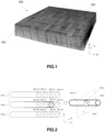
- FIG. 1 shows a three-dimensional reconstruction of the architecture of the reinforcement 300 of a composite material from X-ray tomography images.
- the upper reinforcing ply 301 is made up of reinforcing wires 302 arranged along an axis Y and reinforcing wires 302 arranged along an axis figure 1 .
- the reinforcing axes For example, the reinforcement axes X, Y can form an angle of 45°.
- FIG. 2 shows a schematic representation of a part of the reinforcement 300 of a composite material.
- the part of the reinforcement 300 comprises three layers of reinforcement 301-1, 301-2 and 301-3.
- the first reinforcing ply 301-1 comprises four reinforcing threads 302-10, 302-11, 302-12, 302-13,
- the second reinforcing ply 301-2 comprises four reinforcing threads 302-20, 302-21, 302-22, 302-23
- the third reinforcing ply 301-3 comprises four reinforcing wires 302-30, 302-31, 302-32, 302-33, each reinforcing wire 302-10, 302-11, 302 -12, 302-13, 302-20, 302-21, 302-22, 302-23, 302-30, 302-31, 302-32, 302-33 being arranged along the reinforcement axis Y.
- the reinforcement plies 301 of the same reinforcement 300 can have different reinforcement axes X, Y.
- reinforcement 300 includes two types of plies of reinforcement 301, the first and second type of reinforcement ply 301 each comprising two reinforcement axes X, Y forming an angle of 45° and being superimposed so that the reinforcement axes X, Y of the first type form an angle of 45° ° with the reinforcement axes X, Y of the second type, the reinforcement 300 then comprises four different reinforcement axes.
- reconstruction of the architecture of the reinforcement of a composite material is meant the obtaining of a digital model of the architecture of the reinforcement of the composite material allowing then to carry out digital characterizations of the composite material, for example the thermo-physical and/or thermomechanical properties at each point of the reinforcement or the location of weaving anomalies.
- the method according to a first aspect of the invention makes it possible to obtain a reconstruction of the architecture of the reinforcement 300 of the composite material along a reinforcement axis, for example in the case of the figure 1 , along the X axis or along the Y axis and in the case of figure 2 , along the Y axis.
- the method according to the first aspect of the invention will be applied to the reinforcement axis Y, that is to say that the architecture of the reinforcement 300 of the composite material will be determined along the axis reinforcement Y.
- FIG. 8 is a block diagram illustrating the steps of the method 100 according to the first aspect of the invention.
- a first step 101 of the method 100 consists of acquiring a plurality of images of the reinforcement 300 of the composite material.
- the images are for example acquired by a 3D imaging system having a resolution greater than a threshold, for example a synchrotron radiation imaging system or transmission electron microscope imaging system or X-ray tomography.
- a 3D imaging system having a resolution greater than a threshold, for example a synchrotron radiation imaging system or transmission electron microscope imaging system or X-ray tomography.
- Each image is acquired along a section plane perpendicular to the reinforcement axis Y.
- FIG. 2 shows a schematic representation of an insulated reinforcing wire 302-22, arranged along the reinforcement axis Y and intersected by a section plane 3031 perpendicular to the reinforcement axis Y.
- an image acquired according to the section plane 3031 includes a section of the reinforcing wire 302.
- This section can be defined by its barycenter 3021 and its circumference 3022.
- the resolution threshold of the 3D imaging system is for example 150 ⁇ m to be able to detect the centroids 3021 of reinforcing wires 302 in an acquired image 303 and 40 ⁇ m to be able to detect the circumferences 3022 of reinforcing wires 302 in an image acquired 303.
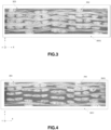
- FIG. 3 There Figure 3 represents an image 303 acquired by X-ray tomography during the first step 101 of the method 100.
- the image 303 is acquired along a section plane 3031 comprising the axes X and Z and perpendicular to the reinforcing axis Y.
- the image 303 includes a plurality of sections of reinforcing wires 302.
- the section planes 3031 of the images 303 acquired during the first step 101 are parallel to each other and not confused, that is to say that the section planes 3031 are spaced from each other along the reinforcement axis Y.
- Each plane of section 3031 can therefore be associated with a position on the reinforcement axis Y.
- the first image 303 is for example associated with the position 0 mm on the reinforcement axis Y, the second image 303 at the 1 mm position on the reinforcement axis Y and the third image 303 at the 2 mm position on the reinforcement axis Y.
- the section planes 3031 may or may not be spaced the same distance along the reinforcement axis Y.
- a second step 102 of the method 100 consists of using a first artificial neural network trained with a first training database to detect the barycenter 3021 of each section of reinforcing wire 302 in each image 303 previously acquired.
- An artificial neural network comprises at least one layer of artificial neurons, each comprising at least one artificial neuron.
- the artificial neurons of the artificial neural network are linked together by synapses and each synapse is assigned a synaptic coefficient.
- the training makes it possible to train the artificial neural network for a predefined task, by updating the synaptic coefficients so as to minimize the error between the output data provided by the artificial neural network and the true output data, that is to say what the artificial neural network should provide as output to complete the predefined task on a certain input data.
- a training database therefore includes input data, each associated with a real output data.
- the first artificial neural network has the function of detecting the barycenter 3021 of each section of reinforcing wire 302 present in an image 303 acquired along a section plane perpendicular to the reinforcement axis Y.
- the first training database therefore includes images of the same or several training composite materials, each acquired along a section plane perpendicular to a reinforcing axis of the training composite material, as well as data on the position of the barycenters 3021 of each section of reinforcing wire 302 in each image 303.
- the composite training material(s) may be identical or different from the composite material for which the architecture of the reinforcement 300 is to be reconstructed.
- the method 100 according to the first aspect of the invention it is possible to reconstruct the architecture of the reinforcement 300 of a composite material before assembly with the matrix or after assembly with the matrix.
- the images of the first training database can therefore be images of reinforcements 300 of composite materials before assembly with their matrices and/or images of reinforcements 300 of composite materials after assembly with their matrices.
- FIG. 4 There figure 4 represents an image 303 acquired by X-ray tomography during the first step 101 of the method 100.
- the barycenter 3021 of each section of reinforcing wire 302 is indicated there.
- image 303 of the Figure 4 was acquired according to a section plan 3031 including the axes X and Z, perpendicular to the reinforcing axis Y.
- Each barycenter 3021 detected in the image 303 is associated with a position in the section plane 3031, that is to say in the reference frame defined by the X and Z axes.
- a third step 103 of the method 100 consists of using a second artificial neural network trained with a second training database to detect the circumference 3022 of each section of reinforcing wire 302 in each image 303 previously acquired.
- the second artificial neural network has the function of detecting the circumference 3022 of each section of reinforcing wire 302 present in an image 303 acquired according to a section plane 3031 perpendicular to the reinforcement axis Y.
- the second training database therefore includes images of the composite training material(s), each acquired along a section plane perpendicular to a reinforcing axis of the composite training material, as well as data on the position of the different points of the circumference 3022 of each section of reinforcing wire 302 in each image 303.
- the images in the first training database may be identical to the images in the second training database.
- the data on the position of the barycenters 3021 included in the first training database and the data on the position of the points of the circumference 3022 included in the second training database can be obtained manually or by algorithms of image processing using, for example, mathematical morphology algorithms.
- the first and second artificial neural networks are for example multi-layer perceptrons or convolutional artificial neural networks.
- FIG. 5 There Figure 5 represents an image 303 acquired by X-ray tomography during the first step 101 of the method 100.
- the circumference 3022 of each section of reinforcing wire 302 has been indicated in the image 303.
- image 303 of the Figure 5 was acquired according to a section plan 3031 including the axes X and Z perpendicular to the reinforcement axis Y.
- Each detected point of the circumference 3022 is associated with a position in the section plane 3031, that is to say in the reference frame defined by the X and Z axes.
- the second step 102 or third step 103 of the method 100 may be optional, that is to say that the architecture of the reinforcement 300 of the composite material can be reconstituted by carrying out only the second step 102 or by carrying out only the third step 103 or by performing the second step 102 and the third step 103.
- a fourth step 104 of the method 100 consists of assigning a label, or “tag” in English, corresponding to a reinforcing wire 302 to each barycenter 3021 detected in one or more previously acquired images 303 chosen as reference images if the second step 102 has been previously carried out or at each circumference 3022 detected in one or more previously acquired images 303 chosen as reference images if the third step 103 has previously been carried out.
- the labels are assigned either to each barycenter 3021 in the reference images in the case where only the second step 102 is carried out or in the case where the second 102 and third step 103 are carried out, either at each circumference 3022 in the reference images in the case where only the third step 103 is carried out or in the case where the second 102 and third step 103 are carried out.
- label assigned to an element means a label assigned to an element allowing it to be identified and distinguished from other elements.
- An acquired reference image is for example selected every N images 303 acquired. For example, if we have 20 acquired images 303 and we want to select a reference acquired image every 5 images, we can for example select the first acquired image 303, the sixth acquired image 303, the eleventh image 303 acquired and the sixteenth image 303 acquired.
- FIG. 6 shows a schematic representation of an acquired reference image 303'.
- the acquired reference image 303' includes three sections of reinforcing wires 302 and therefore three barycenters 3021.
- Each barycenter 3021 is associated with a label L1, L2 or L3.
- the first barycenter 3021 located towards the upper left corner corresponds to the label L1
- the second barycenter 3021 located towards the middle right to the label L2 and the third barycenter 3021 located towards the lower middle to the label L3.
- a fifth step 105 of the method 100 consists of allocating, for each acquired image 303 which has not been selected as the reference acquired image 303', to each barycenter 3021 present in the acquired image 303 if the second step 102 has previously been carried out and/or at each circumference 3022 present in the image 303 acquired if the third step 103 has been previously carried out, the label of the barycenter 3021 and/or the circumference 3022 corresponding in the acquired reference image 303' having been assigned to the fourth step 104.
- the fifth step 105 consists of assigning, for each image 303 acquired not having been selected as acquired reference image 303' , to each barycenter 3021 present in the image 303 acquired the label of the barycenter 3021 corresponding in the acquired reference image and if the third step 103 has also been carried out, to assign, for each image 303 acquired not having been selected as acquired reference image 303', at each circumference 3022 presents in the acquired image 303 the barycenter label 3021 corresponding in the acquired reference image.
- the fifth step 105 consists of assigning, for each image 303 acquired not having been selected as acquired reference image 303', to each circumference 3022 presents in the acquired image 303 the label of the circumference 3022 corresponding in the acquired reference image and if the second step 102 has also been carried out, to assign, for each image 303 acquired not having been selected as image acquired reference 303', at each barycenter 3021 present in the image 303 acquired the label of the circumference 3022 corresponding in the acquired reference image.
- each of the six barycenters 3021 detected in the acquired image 303 will be associated with one of the barycenters 3021 labeled in the acquired reference image 303'.
- the acquired image 303 includes three barycenters 3021, a first barycenter 3021 located in the upper left corner, a second barycenter 3021 located towards the middle right and a third barycenter 3021 located towards the lower middle.
- the fifth step 105 is for example carried out by a grouping algorithm, for example the DBSCAN algorithm.
- the barycenters 3021 and/or the circumferences 3022 of each image 303 acquired are labeled.
- the barycenters 3021 and/or the circumferences 3022 having the same label correspond to the same reinforcing wire 302.
- a sixth step 106 of the method 100 consists of reconstituting the architecture of each reinforcing wire 302 arranged along the reinforcing axis Y.
- the reconstruction of the architecture of each reinforcing wire 302 is carried out from the position, in its section plane 3031, of each barycenter 3021 having the label of the wire reinforcement 302 and the position on the reinforcement axis Y associated with the section plane 3031 and therefore with the image 303 acquired in which the barycenter 3021 was detected.
- the barycenter 3021 of the reinforcing wire 302 is located at the coordinate point (X1, Z1) in a reference frame defined by the axes X and Z in the first image 303, then at the coordinate point (X2, Z2) in the second image 303 and then at the coordinate point (X3, Z3) in the third image 303, we know that the reinforcing wire 302 has a trajectory passing through the point (X1, Z1) at the position 0 mm on the axis reinforcement Y, by the point (X2, Z2) at the 1 mm position and by the point (X3, Z3) at the 2 mm position.
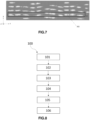
- FIG.7 There Figure 7 represents the position of each barycenter 3021 detected during the second step 102 of the method 100 in a reference frame defined from the reinforcement axis Y and an axis X parallel to the section planes 3031.
- the reconstruction of the architecture of each reinforcing wire 302 is carried out from the position, in its section plane 3031, of each point of the circumference 3022 having the label of the reinforcing wire 302 and the position on the reinforcement axis Y associated with the section plane 3031 and therefore with the image 303 acquired in which the barycenter 3021 was detected.
- a second aspect of the invention concerns a method for automatically reconstituting the complete architecture of the reinforcement 300 of the composite material.
- FIG. 9 is a block diagram illustrating the steps of the method 200 according to the second aspect of the invention.
- the method 200 comprises the steps of the method 100 according to the first aspect of the invention for each axis of reinforcement X, Y of the reinforcement 300.
- the method according to the second aspect of the invention comprises the steps of the method 100 according to the first aspect of the invention for each of the four reinforcement axes .
- each reinforcing wire 302 is known since each reinforcing wire 302 is arranged along any of the reinforcing axes X, Y.
- the last step 201 then consists of reconstituting the complete architecture of the reinforcement 300 of the composite material from the architecture of each reinforcing wire 302 of the reinforcement 300.
- each reinforcing wire 302 in the reference defined by the axes, X, Y and Z.
Landscapes
- Engineering & Computer Science (AREA)
- Physics & Mathematics (AREA)
- Computer Vision & Pattern Recognition (AREA)
- General Physics & Mathematics (AREA)
- Theoretical Computer Science (AREA)
- Geometry (AREA)
- Quality & Reliability (AREA)
- Analysing Materials By The Use Of Radiation (AREA)
- Image Processing (AREA)
Claims (10)
- Verfahren (100) zur automatischen Rekonstruktion der Architektur entlang einer Verstärkungsachse (X, Y) der Verstärkung (300) eines Verbundmaterials, wobei die Verstärkung (300) eine Vielzahl von Verstärkungsfasern (302) umfasst, die entlang der Verstärkungsachse (X, Y) angeordnet sind, wobei das Verfahren (100) einen Schritt umfasst zum- Erfassen (101) einer Vielzahl von Bildern (303) der Verstärkung (300) des Verbundmaterials, wobei jedes Bild (303) entlang einer Schnittebene (3031) erfasst wird, die parallel zu den Schnittebenen (3031) der anderen erfassten Bilder (303) verläuft und nicht mit diesen zusammenfällt, wobei jedem erfassten Bild (303) eine Position auf der Verstärkungsachse (X, Y) zugeordnet ist, die senkrecht zu den Schnittebenen (3031) verläuft, wobei das Verfahren dadurch gekennzeichnet ist, dass es die folgenden Schritte umfasst:- Für jedes erfasste Bild (303), Erfassen (102), unter Verwendung eines ersten künstlichen neuronalen Netzwerks, das mit einer ersten Trainingsdatenbank trainiert wird, des Schwerpunkts (3021) jedes Abschnitts der Verstärkungsfaser (302), der in dem erfassten Bild (303) vorhanden ist, und/oder Erfassen (103), unter Verwendung eines zweiten künstlichen neuronalen Netzwerks, das mit einer zweiten Trainingsdatenbank trainiert wird, des Umfangs (3022) des Abschnitts jeder Verstärkungsfaser (302), der in dem erfassten Bild (303) vorhanden ist;- Für mindestens ein erfasstes Bild, das als Referenzbild (303') bezeichnet wird und aus den erfassten Bildern (303) ausgewählt wird, Zuordnung (104) eines Labels, das einer Verstärkungsfaser (302) entspricht, zu jedem erfassten Schwerpunkt (3021) oder zu jedem erfassten Umfang (3022) in dem erfassten Referenzbild (303');- Für jedes erfasste Bild (303), das nicht als erfasstes Referenzbild (303') ausgewählt wurde, Zuordnen (105) des Labels des entsprechenden Schwerpunkts (3021) oder Umfangs (3022) in dem als Referenz erfassten Bild (303') zu jedem erfassten Schwerpunkt (3021) und/oder zu jedem erfassten Umfang (3022) in dem erfassten Bild (303);- Rekonstruktion (106) der Architektur jeder Verstärkungsfaser (302), die entlang der Verstärkungsachse (X, Y) angeordnet ist, aus jedem erfassten Schwerpunkt (3021) und/oder jedem erfassten Umfang (3022), der das Label der Verstärkungsfaser (302) hat, und der Position auf der Verstärkungsachse (X, Y), die dem erfassten Bild (303) zugeordnet ist, in dem der Schwerpunkt (3021) und/oder der Umfang (3022) erfasst wurden.
- Verfahren (100) nach Anspruch 1, dadurch gekennzeichnet, dass das erste und das zweite künstliche neuronale Netzwerk mehrschichtige Perzeptrone und/oder gefaltete künstliche neuronale Netzwerke sind.
- Verfahren (100) nach einem der vorhergehenden Ansprüche, dadurch gekennzeichnet, dass die erste und die zweite Trainingsdatenbank jeweils eine Vielzahl von Bildern von mindestens einem Trainingsverbundmaterial umfassen, die jeweils entlang einer Schnittebene senkrecht zu einer Verstärkungsachse des Trainingsverbundmaterials erfasst werden.
- Verfahren (100) nach einem der vorhergehenden Ansprüche, dadurch gekennzeichnet, dass der Zuordnungsschritt (105) mithilfe eines Gruppierungsalgorithmus durchgeführt wird.
- Verfahren (100) nach einem der vorhergehenden Ansprüche, dadurch gekennzeichnet, dass die Bilder (303) von einem 3D-Bildgebungssystem mit einer höheren Auflösung als ein Schwellenwert erfasst werden.
- Verfahren (100) nach Anspruch 5, dadurch gekennzeichnet, dass der Schwellenwert 150 µm für die Bilder (303) beträgt, die für die Erfassung (102) der Schwerpunkte (3021) erfasst werden, bzw. 40 µm für die Bilder (303), die für die Erfassung (103) der Umfänge (3022) erfasst werden.
- Verfahren (100) nach einem der Ansprüche 5 oder 6, dadurch gekennzeichnet, dass die Bilder (303) durch Synchrotronstrahlungs-Bildgebung, Transmissionselektronenmikroskop-Bildgebung oder Röntgentomographie erfasst werden.
- Verfahren (200) zur automatischen Wiederherstellung der Architektur der Verstärkung (300) eines Verbundmaterials, dadurch gekennzeichnet, dass es Folgendes umfasst:- für jede Verstärkungsachse (X ,Y) des Verbundmaterials die Schritte (101, 102, 103, 104, 105, 106) des Verfahrens (100) zur automatischen Rekonstruktion der Architektur der Verstärkung (300) des Verbundmaterials entlang der Verstärkungsachse (X, Y) gemäß einem der vorhergehenden Ansprüche,- einen Schritt zur Rekonstruktion (201) der Architektur der Verstärkung (300) des Verbundmaterials aus der Architektur jeder Verstärkungsfaser (302) entlang jeder Verstärkungsachse (X, Y).
- Computerprogrammprodukt mit Anweisungen, die, wenn das Programm von einem Computer ausgeführt wird, diesen dazu veranlassen, die Schritte des Verfahrens (100, 200) nach einem der vorhergehenden Ansprüche auszuführen.
- Computerlesbares Aufzeichnungsträger, der Anweisungen enthält, die, wenn sie von einem Computer ausgeführt werden, diesen dazu veranlassen, die Schritte des Verfahrens (100, 200) nach einem der Ansprüche 1 bis 8 auszuführen.
Applications Claiming Priority (2)
| Application Number | Priority Date | Filing Date | Title |
|---|---|---|---|
| FR1914066A FR3104301B1 (fr) | 2019-12-10 | 2019-12-10 | Procede de reconstitution automatique de l’architecture du renfort d’un materiau composite |
| PCT/FR2020/052350 WO2021116602A1 (fr) | 2019-12-10 | 2020-12-09 | Procédé de reconstitution automatique de l'architecture du renfort d'un matériau composite |
Publications (2)
| Publication Number | Publication Date |
|---|---|
| EP4073751A1 EP4073751A1 (de) | 2022-10-19 |
| EP4073751B1 true EP4073751B1 (de) | 2023-11-22 |
Family
ID=69903394
Family Applications (1)
| Application Number | Title | Priority Date | Filing Date |
|---|---|---|---|
| EP20842019.0A Active EP4073751B1 (de) | 2019-12-10 | 2020-12-09 | Verfahren zum automatischen wiederaufbau der verstärkungsarchitektur eines verbundmaterials |
Country Status (5)
| Country | Link |
|---|---|
| US (1) | US12159396B2 (de) |
| EP (1) | EP4073751B1 (de) |
| CN (1) | CN115088011B (de) |
| FR (1) | FR3104301B1 (de) |
| WO (1) | WO2021116602A1 (de) |
Families Citing this family (1)
| Publication number | Priority date | Publication date | Assignee | Title |
|---|---|---|---|---|
| FR3132772B1 (fr) * | 2022-02-11 | 2023-12-29 | Safran Aircraft Engines | Procédé d’analyse tomographique |
Family Cites Families (6)
| Publication number | Priority date | Publication date | Assignee | Title |
|---|---|---|---|---|
| WO2015024580A1 (en) * | 2013-08-19 | 2015-02-26 | Universidad De Burgos | Computer implemented method to obtain the orientations of fibres inside composite materials using computed tomography scan |
| FR3010523B1 (fr) * | 2013-09-06 | 2015-09-25 | Safran | Procede de caracterisation d'une piece en materiau composite |
| JP6118698B2 (ja) * | 2013-09-30 | 2017-04-19 | 株式会社Ihi | 画像解析装置及びプログラム |
| CN106202728B (zh) * | 2016-07-12 | 2019-04-09 | 哈尔滨工业大学 | 基于Micro-CT三维编织复合材料非均匀Voxel网格离散方法 |
| CN109903350B (zh) * | 2017-12-07 | 2021-08-06 | 上海寒武纪信息科技有限公司 | 图像压缩方法及相关装置 |
| CN109886951A (zh) * | 2019-02-22 | 2019-06-14 | 北京旷视科技有限公司 | 视频处理方法、装置及电子设备 |
-
2019
- 2019-12-10 FR FR1914066A patent/FR3104301B1/fr active Active
-
2020
- 2020-12-09 WO PCT/FR2020/052350 patent/WO2021116602A1/fr not_active Ceased
- 2020-12-09 CN CN202080096032.XA patent/CN115088011B/zh active Active
- 2020-12-09 EP EP20842019.0A patent/EP4073751B1/de active Active
- 2020-12-09 US US17/783,890 patent/US12159396B2/en active Active
Also Published As
| Publication number | Publication date |
|---|---|
| CN115088011A (zh) | 2022-09-20 |
| US12159396B2 (en) | 2024-12-03 |
| CN115088011B (zh) | 2026-03-17 |
| WO2021116602A1 (fr) | 2021-06-17 |
| EP4073751A1 (de) | 2022-10-19 |
| FR3104301B1 (fr) | 2021-11-05 |
| FR3104301A1 (fr) | 2021-06-11 |
| US20230009054A1 (en) | 2023-01-12 |
Similar Documents
| Publication | Publication Date | Title |
|---|---|---|
| WO2019155471A1 (en) | Method of deep learning-based examination of a semiconductor specimen and system thereof | |
| FR3050826A1 (fr) | Procede de controle non-destructif par apprentissage | |
| EP4073751B1 (de) | Verfahren zum automatischen wiederaufbau der verstärkungsarchitektur eines verbundmaterials | |
| JP7254921B2 (ja) | 半導体試料の欠陥の分類 | |
| FR3050274A1 (fr) | Procede d'analyse topologique d'une piece composite | |
| CN120235842A (zh) | 塑料容器的智能化检测方法、装置及设备 | |
| EP4128152B1 (de) | Verfahren und system zur skelettierung der stränge eines verbundwerkstoffteils in einem 3d-bild | |
| CN120563423A (zh) | 一种3d视觉检测的配套线缆生产监控方法及系统 | |
| EP2145175B1 (de) | Verfahren und maschine zur überprüfung transparenter oder transluzenter artikel | |
| Oleff et al. | Determination of quality classes for material extrusion additive manufacturing using image processing | |
| EP3872481B1 (de) | Verfahren und systeme zur detektion von verunreinigungen im material für additive fertigung | |
| KR20190048841A (ko) | 자산과 임무간 의존성 기반의 임무 영향도 분석 방법 | |
| EP4558810A1 (de) | Verfahren und vorrichtung zur inspektion von glasbehältern gemäss mindestens zwei betriebsarten im hinblick auf die klassifizierung der behälter durch ihre glasdefekte | |
| FR2660463A1 (fr) | Dispositif de reconnaissance de caracteres, procede d'extraction de caracteres et procede de reconnaissance de chiffres successifs utilisant un tel dispositif. | |
| EP4252182A1 (de) | Verfahren zur automatischen suche nach mindestens einem textilen muster in einer verbundwerkstoffverstärkung | |
| FR3122273A1 (fr) | Procédé de génération automatique d’une image artificielle du renfort d’un matériau composite | |
| FR3113325A1 (fr) | Système et Procédé de Reconnaissance Automatique des Interfaces dans des Profils de Produits des Pneumatiques | |
| Robotyshyn et al. | Surface defect detection based on deep learning approach. | |
| EP4639491A1 (de) | Verfahren zur identifizierung und charakterisierung von defekten in einem objekt, einschliesslich rissen in einer bremsscheibe oder einem bremssattel mittels künstlicher intelligenz | |
| WO2022223902A1 (fr) | Procédé de reconstitution automatique de l'architecture du renfort d'un matériau composite | |
| Bordbar et al. | Palynological study of Jurinea (Asteraceae) and related genera from flora of Iran | |
| EP4702532A1 (de) | Verfahren zur bestimmung einer neutralen faser eines strangs aus einem gewebten verbundstoff | |
| Ünal et al. | A Big Data Application in Manufacturing Industry-Computer Vision to Detect Defects on Bearings | |
| Mu et al. | Machine learning-inspired image processing for accurate length characterization of complexly crossed hemp fibers | |
| FR3148838A1 (fr) | Procede de determination d’une representation d’un squelette d’un toron d’un materiau composite tisse |
Legal Events
| Date | Code | Title | Description |
|---|---|---|---|
| STAA | Information on the status of an ep patent application or granted ep patent |
Free format text: STATUS: UNKNOWN |
|
| STAA | Information on the status of an ep patent application or granted ep patent |
Free format text: STATUS: THE INTERNATIONAL PUBLICATION HAS BEEN MADE |
|
| PUAI | Public reference made under article 153(3) epc to a published international application that has entered the european phase |
Free format text: ORIGINAL CODE: 0009012 |
|
| STAA | Information on the status of an ep patent application or granted ep patent |
Free format text: STATUS: REQUEST FOR EXAMINATION WAS MADE |
|
| 17P | Request for examination filed |
Effective date: 20220621 |
|
| AK | Designated contracting states |
Kind code of ref document: A1 Designated state(s): AL AT BE BG CH CY CZ DE DK EE ES FI FR GB GR HR HU IE IS IT LI LT LU LV MC MK MT NL NO PL PT RO RS SE SI SK SM TR |
|
| DAV | Request for validation of the european patent (deleted) | ||
| DAX | Request for extension of the european patent (deleted) | ||
| GRAP | Despatch of communication of intention to grant a patent |
Free format text: ORIGINAL CODE: EPIDOSNIGR1 |
|
| STAA | Information on the status of an ep patent application or granted ep patent |
Free format text: STATUS: GRANT OF PATENT IS INTENDED |
|
| INTG | Intention to grant announced |
Effective date: 20230707 |
|
| RIC1 | Information provided on ipc code assigned before grant |
Ipc: G01N 21/88 20060101ALI20230623BHEP Ipc: G01N 21/84 20060101ALI20230623BHEP Ipc: G06T 7/12 20170101ALI20230623BHEP Ipc: G06T 7/174 20170101ALI20230623BHEP Ipc: G06T 7/66 20170101ALI20230623BHEP Ipc: G06T 7/11 20170101AFI20230623BHEP |
|
| GRAS | Grant fee paid |
Free format text: ORIGINAL CODE: EPIDOSNIGR3 |
|
| GRAA | (expected) grant |
Free format text: ORIGINAL CODE: 0009210 |
|
| STAA | Information on the status of an ep patent application or granted ep patent |
Free format text: STATUS: THE PATENT HAS BEEN GRANTED |
|
| AK | Designated contracting states |
Kind code of ref document: B1 Designated state(s): AL AT BE BG CH CY CZ DE DK EE ES FI FR GB GR HR HU IE IS IT LI LT LU LV MC MK MT NL NO PL PT RO RS SE SI SK SM TR |
|
| REG | Reference to a national code |
Ref country code: GB Ref legal event code: FG4D Free format text: NOT ENGLISH |
|
| REG | Reference to a national code |
Ref country code: CH Ref legal event code: EP |
|
| REG | Reference to a national code |
Ref country code: DE Ref legal event code: R096 Ref document number: 602020021641 Country of ref document: DE |
|
| REG | Reference to a national code |
Ref country code: IE Ref legal event code: FG4D Free format text: LANGUAGE OF EP DOCUMENT: FRENCH |
|
| REG | Reference to a national code |
Ref country code: LT Ref legal event code: MG9D |
|
| REG | Reference to a national code |
Ref country code: NL Ref legal event code: MP Effective date: 20231122 |
|
| PG25 | Lapsed in a contracting state [announced via postgrant information from national office to epo] |
Ref country code: GR Free format text: LAPSE BECAUSE OF FAILURE TO SUBMIT A TRANSLATION OF THE DESCRIPTION OR TO PAY THE FEE WITHIN THE PRESCRIBED TIME-LIMIT Effective date: 20240223 |
|
| PG25 | Lapsed in a contracting state [announced via postgrant information from national office to epo] |
Ref country code: IS Free format text: LAPSE BECAUSE OF FAILURE TO SUBMIT A TRANSLATION OF THE DESCRIPTION OR TO PAY THE FEE WITHIN THE PRESCRIBED TIME-LIMIT Effective date: 20240322 |
|
| PG25 | Lapsed in a contracting state [announced via postgrant information from national office to epo] |
Ref country code: LT Free format text: LAPSE BECAUSE OF FAILURE TO SUBMIT A TRANSLATION OF THE DESCRIPTION OR TO PAY THE FEE WITHIN THE PRESCRIBED TIME-LIMIT Effective date: 20231122 |
|
| REG | Reference to a national code |
Ref country code: AT Ref legal event code: MK05 Ref document number: 1634529 Country of ref document: AT Kind code of ref document: T Effective date: 20231122 |
|
| PG25 | Lapsed in a contracting state [announced via postgrant information from national office to epo] |
Ref country code: NL Free format text: LAPSE BECAUSE OF FAILURE TO SUBMIT A TRANSLATION OF THE DESCRIPTION OR TO PAY THE FEE WITHIN THE PRESCRIBED TIME-LIMIT Effective date: 20231122 |
|
| PG25 | Lapsed in a contracting state [announced via postgrant information from national office to epo] |
Ref country code: AT Free format text: LAPSE BECAUSE OF FAILURE TO SUBMIT A TRANSLATION OF THE DESCRIPTION OR TO PAY THE FEE WITHIN THE PRESCRIBED TIME-LIMIT Effective date: 20231122 |
|
| PG25 | Lapsed in a contracting state [announced via postgrant information from national office to epo] |
Ref country code: ES Free format text: LAPSE BECAUSE OF FAILURE TO SUBMIT A TRANSLATION OF THE DESCRIPTION OR TO PAY THE FEE WITHIN THE PRESCRIBED TIME-LIMIT Effective date: 20231122 |
|
| PG25 | Lapsed in a contracting state [announced via postgrant information from national office to epo] |
Ref country code: NL Free format text: LAPSE BECAUSE OF FAILURE TO SUBMIT A TRANSLATION OF THE DESCRIPTION OR TO PAY THE FEE WITHIN THE PRESCRIBED TIME-LIMIT Effective date: 20231122 Ref country code: LT Free format text: LAPSE BECAUSE OF FAILURE TO SUBMIT A TRANSLATION OF THE DESCRIPTION OR TO PAY THE FEE WITHIN THE PRESCRIBED TIME-LIMIT Effective date: 20231122 Ref country code: IS Free format text: LAPSE BECAUSE OF FAILURE TO SUBMIT A TRANSLATION OF THE DESCRIPTION OR TO PAY THE FEE WITHIN THE PRESCRIBED TIME-LIMIT Effective date: 20240322 Ref country code: GR Free format text: LAPSE BECAUSE OF FAILURE TO SUBMIT A TRANSLATION OF THE DESCRIPTION OR TO PAY THE FEE WITHIN THE PRESCRIBED TIME-LIMIT Effective date: 20240223 Ref country code: ES Free format text: LAPSE BECAUSE OF FAILURE TO SUBMIT A TRANSLATION OF THE DESCRIPTION OR TO PAY THE FEE WITHIN THE PRESCRIBED TIME-LIMIT Effective date: 20231122 Ref country code: BG Free format text: LAPSE BECAUSE OF FAILURE TO SUBMIT A TRANSLATION OF THE DESCRIPTION OR TO PAY THE FEE WITHIN THE PRESCRIBED TIME-LIMIT Effective date: 20240222 Ref country code: AT Free format text: LAPSE BECAUSE OF FAILURE TO SUBMIT A TRANSLATION OF THE DESCRIPTION OR TO PAY THE FEE WITHIN THE PRESCRIBED TIME-LIMIT Effective date: 20231122 Ref country code: PT Free format text: LAPSE BECAUSE OF FAILURE TO SUBMIT A TRANSLATION OF THE DESCRIPTION OR TO PAY THE FEE WITHIN THE PRESCRIBED TIME-LIMIT Effective date: 20240322 |
|
| PG25 | Lapsed in a contracting state [announced via postgrant information from national office to epo] |
Ref country code: SE Free format text: LAPSE BECAUSE OF FAILURE TO SUBMIT A TRANSLATION OF THE DESCRIPTION OR TO PAY THE FEE WITHIN THE PRESCRIBED TIME-LIMIT Effective date: 20231122 Ref country code: RS Free format text: LAPSE BECAUSE OF FAILURE TO SUBMIT A TRANSLATION OF THE DESCRIPTION OR TO PAY THE FEE WITHIN THE PRESCRIBED TIME-LIMIT Effective date: 20231122 Ref country code: PL Free format text: LAPSE BECAUSE OF FAILURE TO SUBMIT A TRANSLATION OF THE DESCRIPTION OR TO PAY THE FEE WITHIN THE PRESCRIBED TIME-LIMIT Effective date: 20231122 Ref country code: NO Free format text: LAPSE BECAUSE OF FAILURE TO SUBMIT A TRANSLATION OF THE DESCRIPTION OR TO PAY THE FEE WITHIN THE PRESCRIBED TIME-LIMIT Effective date: 20240222 Ref country code: LV Free format text: LAPSE BECAUSE OF FAILURE TO SUBMIT A TRANSLATION OF THE DESCRIPTION OR TO PAY THE FEE WITHIN THE PRESCRIBED TIME-LIMIT Effective date: 20231122 Ref country code: HR Free format text: LAPSE BECAUSE OF FAILURE TO SUBMIT A TRANSLATION OF THE DESCRIPTION OR TO PAY THE FEE WITHIN THE PRESCRIBED TIME-LIMIT Effective date: 20231122 |
|
| PG25 | Lapsed in a contracting state [announced via postgrant information from national office to epo] |
Ref country code: DK Free format text: LAPSE BECAUSE OF FAILURE TO SUBMIT A TRANSLATION OF THE DESCRIPTION OR TO PAY THE FEE WITHIN THE PRESCRIBED TIME-LIMIT Effective date: 20231122 |
|
| PG25 | Lapsed in a contracting state [announced via postgrant information from national office to epo] |
Ref country code: CZ Free format text: LAPSE BECAUSE OF FAILURE TO SUBMIT A TRANSLATION OF THE DESCRIPTION OR TO PAY THE FEE WITHIN THE PRESCRIBED TIME-LIMIT Effective date: 20231122 |
|
| PG25 | Lapsed in a contracting state [announced via postgrant information from national office to epo] |
Ref country code: SK Free format text: LAPSE BECAUSE OF FAILURE TO SUBMIT A TRANSLATION OF THE DESCRIPTION OR TO PAY THE FEE WITHIN THE PRESCRIBED TIME-LIMIT Effective date: 20231122 |
|
| PG25 | Lapsed in a contracting state [announced via postgrant information from national office to epo] |
Ref country code: SM Free format text: LAPSE BECAUSE OF FAILURE TO SUBMIT A TRANSLATION OF THE DESCRIPTION OR TO PAY THE FEE WITHIN THE PRESCRIBED TIME-LIMIT Effective date: 20231122 Ref country code: SK Free format text: LAPSE BECAUSE OF FAILURE TO SUBMIT A TRANSLATION OF THE DESCRIPTION OR TO PAY THE FEE WITHIN THE PRESCRIBED TIME-LIMIT Effective date: 20231122 Ref country code: RO Free format text: LAPSE BECAUSE OF FAILURE TO SUBMIT A TRANSLATION OF THE DESCRIPTION OR TO PAY THE FEE WITHIN THE PRESCRIBED TIME-LIMIT Effective date: 20231122 Ref country code: IT Free format text: LAPSE BECAUSE OF FAILURE TO SUBMIT A TRANSLATION OF THE DESCRIPTION OR TO PAY THE FEE WITHIN THE PRESCRIBED TIME-LIMIT Effective date: 20231122 Ref country code: EE Free format text: LAPSE BECAUSE OF FAILURE TO SUBMIT A TRANSLATION OF THE DESCRIPTION OR TO PAY THE FEE WITHIN THE PRESCRIBED TIME-LIMIT Effective date: 20231122 Ref country code: DK Free format text: LAPSE BECAUSE OF FAILURE TO SUBMIT A TRANSLATION OF THE DESCRIPTION OR TO PAY THE FEE WITHIN THE PRESCRIBED TIME-LIMIT Effective date: 20231122 Ref country code: CZ Free format text: LAPSE BECAUSE OF FAILURE TO SUBMIT A TRANSLATION OF THE DESCRIPTION OR TO PAY THE FEE WITHIN THE PRESCRIBED TIME-LIMIT Effective date: 20231122 |
|
| REG | Reference to a national code |
Ref country code: CH Ref legal event code: PL |
|
| PG25 | Lapsed in a contracting state [announced via postgrant information from national office to epo] |
Ref country code: LU Free format text: LAPSE BECAUSE OF NON-PAYMENT OF DUE FEES Effective date: 20231209 |
|
| REG | Reference to a national code |
Ref country code: DE Ref legal event code: R097 Ref document number: 602020021641 Country of ref document: DE |
|
| PG25 | Lapsed in a contracting state [announced via postgrant information from national office to epo] |
Ref country code: MC Free format text: LAPSE BECAUSE OF FAILURE TO SUBMIT A TRANSLATION OF THE DESCRIPTION OR TO PAY THE FEE WITHIN THE PRESCRIBED TIME-LIMIT Effective date: 20231122 |
|
| REG | Reference to a national code |
Ref country code: BE Ref legal event code: MM Effective date: 20231231 |
|
| PG25 | Lapsed in a contracting state [announced via postgrant information from national office to epo] |
Ref country code: MC Free format text: LAPSE BECAUSE OF FAILURE TO SUBMIT A TRANSLATION OF THE DESCRIPTION OR TO PAY THE FEE WITHIN THE PRESCRIBED TIME-LIMIT Effective date: 20231122 Ref country code: LU Free format text: LAPSE BECAUSE OF NON-PAYMENT OF DUE FEES Effective date: 20231209 |
|
| PLBE | No opposition filed within time limit |
Free format text: ORIGINAL CODE: 0009261 |
|
| STAA | Information on the status of an ep patent application or granted ep patent |
Free format text: STATUS: NO OPPOSITION FILED WITHIN TIME LIMIT |
|
| REG | Reference to a national code |
Ref country code: IE Ref legal event code: MM4A |
|
| PG25 | Lapsed in a contracting state [announced via postgrant information from national office to epo] |
Ref country code: IE Free format text: LAPSE BECAUSE OF NON-PAYMENT OF DUE FEES Effective date: 20231209 |
|
| PG25 | Lapsed in a contracting state [announced via postgrant information from national office to epo] |
Ref country code: BE Free format text: LAPSE BECAUSE OF NON-PAYMENT OF DUE FEES Effective date: 20231231 |
|
| PG25 | Lapsed in a contracting state [announced via postgrant information from national office to epo] |
Ref country code: CH Free format text: LAPSE BECAUSE OF NON-PAYMENT OF DUE FEES Effective date: 20231231 |
|
| PG25 | Lapsed in a contracting state [announced via postgrant information from national office to epo] |
Ref country code: SI Free format text: LAPSE BECAUSE OF FAILURE TO SUBMIT A TRANSLATION OF THE DESCRIPTION OR TO PAY THE FEE WITHIN THE PRESCRIBED TIME-LIMIT Effective date: 20231122 |
|
| 26N | No opposition filed |
Effective date: 20240823 |
|
| PG25 | Lapsed in a contracting state [announced via postgrant information from national office to epo] |
Ref country code: SI Free format text: LAPSE BECAUSE OF FAILURE TO SUBMIT A TRANSLATION OF THE DESCRIPTION OR TO PAY THE FEE WITHIN THE PRESCRIBED TIME-LIMIT Effective date: 20231122 Ref country code: IE Free format text: LAPSE BECAUSE OF NON-PAYMENT OF DUE FEES Effective date: 20231209 Ref country code: CH Free format text: LAPSE BECAUSE OF NON-PAYMENT OF DUE FEES Effective date: 20231231 Ref country code: BE Free format text: LAPSE BECAUSE OF NON-PAYMENT OF DUE FEES Effective date: 20231231 |
|
| PG25 | Lapsed in a contracting state [announced via postgrant information from national office to epo] |
Ref country code: FI Free format text: LAPSE BECAUSE OF FAILURE TO SUBMIT A TRANSLATION OF THE DESCRIPTION OR TO PAY THE FEE WITHIN THE PRESCRIBED TIME-LIMIT Effective date: 20231122 |
|
| PG25 | Lapsed in a contracting state [announced via postgrant information from national office to epo] |
Ref country code: CY Free format text: LAPSE BECAUSE OF FAILURE TO SUBMIT A TRANSLATION OF THE DESCRIPTION OR TO PAY THE FEE WITHIN THE PRESCRIBED TIME-LIMIT; INVALID AB INITIO Effective date: 20201209 |
|
| PG25 | Lapsed in a contracting state [announced via postgrant information from national office to epo] |
Ref country code: HU Free format text: LAPSE BECAUSE OF FAILURE TO SUBMIT A TRANSLATION OF THE DESCRIPTION OR TO PAY THE FEE WITHIN THE PRESCRIBED TIME-LIMIT; INVALID AB INITIO Effective date: 20201209 |
|
| PG25 | Lapsed in a contracting state [announced via postgrant information from national office to epo] |
Ref country code: TR Free format text: LAPSE BECAUSE OF FAILURE TO SUBMIT A TRANSLATION OF THE DESCRIPTION OR TO PAY THE FEE WITHIN THE PRESCRIBED TIME-LIMIT Effective date: 20231122 |
|
| PGFP | Annual fee paid to national office [announced via postgrant information from national office to epo] |
Ref country code: GB Payment date: 20251229 Year of fee payment: 6 |
|
| PGFP | Annual fee paid to national office [announced via postgrant information from national office to epo] |
Ref country code: FR Payment date: 20251222 Year of fee payment: 6 |
|
| PGFP | Annual fee paid to national office [announced via postgrant information from national office to epo] |
Ref country code: DE Payment date: 20251222 Year of fee payment: 6 |