EP4072256A1 - Multi-temperature control cabinet and scheduling method for multi-temperature control cabinet - Google Patents
Multi-temperature control cabinet and scheduling method for multi-temperature control cabinet Download PDFInfo
- Publication number
- EP4072256A1 EP4072256A1 EP22166765.2A EP22166765A EP4072256A1 EP 4072256 A1 EP4072256 A1 EP 4072256A1 EP 22166765 A EP22166765 A EP 22166765A EP 4072256 A1 EP4072256 A1 EP 4072256A1
- Authority
- EP
- European Patent Office
- Prior art keywords
- air
- humidity
- cabinet
- air conditioner
- temperature
- Prior art date
- Legal status (The legal status is an assumption and is not a legal conclusion. Google has not performed a legal analysis and makes no representation as to the accuracy of the status listed.)
- Granted
Links
- 238000000034 method Methods 0.000 title claims abstract description 47
- 238000009423 ventilation Methods 0.000 claims abstract description 132
- 238000012544 monitoring process Methods 0.000 claims abstract description 113
- 230000007423 decrease Effects 0.000 claims description 10
- 239000000463 material Substances 0.000 claims description 4
- 239000002184 metal Substances 0.000 claims description 3
- 238000009833 condensation Methods 0.000 abstract description 16
- 230000005494 condensation Effects 0.000 abstract description 16
- 238000005057 refrigeration Methods 0.000 description 10
- 238000010586 diagram Methods 0.000 description 8
- 230000008569 process Effects 0.000 description 6
- 230000000694 effects Effects 0.000 description 4
- 238000009434 installation Methods 0.000 description 4
- 230000009471 action Effects 0.000 description 3
- 230000005611 electricity Effects 0.000 description 3
- 238000005516 engineering process Methods 0.000 description 3
- 238000012545 processing Methods 0.000 description 3
- 230000003068 static effect Effects 0.000 description 3
- 230000000712 assembly Effects 0.000 description 2
- 238000000429 assembly Methods 0.000 description 2
- 238000012423 maintenance Methods 0.000 description 2
- 239000000956 alloy Substances 0.000 description 1
- 229910045601 alloy Inorganic materials 0.000 description 1
- 239000010960 cold rolled steel Substances 0.000 description 1
- 238000001816 cooling Methods 0.000 description 1
- 230000003247 decreasing effect Effects 0.000 description 1
- 238000005265 energy consumption Methods 0.000 description 1
- 230000003993 interaction Effects 0.000 description 1
- 238000012986 modification Methods 0.000 description 1
- 230000004048 modification Effects 0.000 description 1
- 230000002265 prevention Effects 0.000 description 1
Images


Classifications
-
- H—ELECTRICITY
- H05—ELECTRIC TECHNIQUES NOT OTHERWISE PROVIDED FOR
- H05K—PRINTED CIRCUITS; CASINGS OR CONSTRUCTIONAL DETAILS OF ELECTRIC APPARATUS; MANUFACTURE OF ASSEMBLAGES OF ELECTRICAL COMPONENTS
- H05K7/00—Constructional details common to different types of electric apparatus
- H05K7/20—Modifications to facilitate cooling, ventilating, or heating
- H05K7/20009—Modifications to facilitate cooling, ventilating, or heating using a gaseous coolant in electronic enclosures
- H05K7/20136—Forced ventilation, e.g. by fans
- H05K7/20145—Means for directing air flow, e.g. ducts, deflectors, plenum or guides
-
- H—ELECTRICITY
- H05—ELECTRIC TECHNIQUES NOT OTHERWISE PROVIDED FOR
- H05K—PRINTED CIRCUITS; CASINGS OR CONSTRUCTIONAL DETAILS OF ELECTRIC APPARATUS; MANUFACTURE OF ASSEMBLAGES OF ELECTRICAL COMPONENTS
- H05K7/00—Constructional details common to different types of electric apparatus
- H05K7/20—Modifications to facilitate cooling, ventilating, or heating
- H05K7/20536—Modifications to facilitate cooling, ventilating, or heating for racks or cabinets of standardised dimensions, e.g. electronic racks for aircraft or telecommunication equipment
- H05K7/207—Thermal management, e.g. cabinet temperature control
-
- H—ELECTRICITY
- H05—ELECTRIC TECHNIQUES NOT OTHERWISE PROVIDED FOR
- H05K—PRINTED CIRCUITS; CASINGS OR CONSTRUCTIONAL DETAILS OF ELECTRIC APPARATUS; MANUFACTURE OF ASSEMBLAGES OF ELECTRICAL COMPONENTS
- H05K5/00—Casings, cabinets or drawers for electric apparatus
- H05K5/02—Details
- H05K5/0213—Venting apertures; Constructional details thereof
-
- H—ELECTRICITY
- H05—ELECTRIC TECHNIQUES NOT OTHERWISE PROVIDED FOR
- H05K—PRINTED CIRCUITS; CASINGS OR CONSTRUCTIONAL DETAILS OF ELECTRIC APPARATUS; MANUFACTURE OF ASSEMBLAGES OF ELECTRICAL COMPONENTS
- H05K5/00—Casings, cabinets or drawers for electric apparatus
- H05K5/02—Details
-
- H—ELECTRICITY
- H05—ELECTRIC TECHNIQUES NOT OTHERWISE PROVIDED FOR
- H05K—PRINTED CIRCUITS; CASINGS OR CONSTRUCTIONAL DETAILS OF ELECTRIC APPARATUS; MANUFACTURE OF ASSEMBLAGES OF ELECTRICAL COMPONENTS
- H05K5/00—Casings, cabinets or drawers for electric apparatus
- H05K5/02—Details
- H05K5/0217—Mechanical details of casings
- H05K5/0226—Hinges
-
- H—ELECTRICITY
- H05—ELECTRIC TECHNIQUES NOT OTHERWISE PROVIDED FOR
- H05K—PRINTED CIRCUITS; CASINGS OR CONSTRUCTIONAL DETAILS OF ELECTRIC APPARATUS; MANUFACTURE OF ASSEMBLAGES OF ELECTRICAL COMPONENTS
- H05K7/00—Constructional details common to different types of electric apparatus
- H05K7/20—Modifications to facilitate cooling, ventilating, or heating
- H05K7/20009—Modifications to facilitate cooling, ventilating, or heating using a gaseous coolant in electronic enclosures
- H05K7/20209—Thermal management, e.g. fan control
Definitions
- the present invention relates to the field of cabinet technologies, and in particular, to a multi-temperature control cabinet and a scheduling method for a multi-temperature control cabinet.
- a cabinet is a freestanding or self-supporting housing that accommodates electrical or electronic equipment.
- a door, a removable or non-removable side panel, and a backplane are usually configured for the cabinet.
- the cabinet is an indispensable component of electrical equipment and is a carrier of electrical control equipment.
- the cabinet is usually made of a cold-rolled steel plate or an alloy, and can provide protection functions such as waterproof, dustproof, and electromagnetic interference prevention for a stored device.
- a temperature adjustment system is disposed in the cabinet to ensure that the device in the cabinet can run in a stable environment.
- an air conditioner and direct ventilation are disposed in a cabinet to adjust temperature in the cabinet. Both the air conditioner and the direct ventilation are connected to a temperature control component.
- the temperature control component is configured to: monitor the temperature in the cabinet, and control turning-on and turning-off of the air conditioner and the direct ventilation by using the temperature in the cabinet. Specifically, when the temperature in the cabinet is relatively high, the air conditioner starts to run, and the direct ventilation does not run; or when the temperature in the cabinet is relatively low, the air conditioner is turned off, and the direct ventilation starts to work, to adjust the temperature in the cabinet.
- the controlling the turning-on and the turning-off of the air conditioner and the direct ventilation by using the temperature control component causes fluctuation of humidity in the cabinet, and in a serious case, causes a high-humidity alarm and condensation of a device in the cabinet.
- Embodiments of this application provide a multi-temperature control cabinet and a scheduling method for a multi-temperature control cabinet, to resolve a technical problem that condensation is likely to be caused due to fluctuation of humidity in the cabinet.
- a first aspect of embodiments of this application provides a multi-temperature control cabinet, including a cabinet body, a cabinet door, and a refrigerating system.
- the refrigerating system includes at least one air conditioner, at least one direct ventilation unit, and an environment monitoring apparatus.
- Both the air conditioner and the direct ventilation unit are disposed on the cabinet door, and the air conditioner and the direct ventilation unit are disposed in parallel in a height direction of the cabinet door.
- An air guide assembly is disposed between the direct ventilation unit and an air exhaust vent of the air conditioner.
- the environment monitoring apparatus is connected to both the air conditioner and the direct ventilation unit, and the environment monitoring apparatus is configured to: monitor temperature and humidity in the cabinet body, and control turning-on and turning-off of the air conditioner and the direct ventilation unit based on the temperature and the humidity in the cabinet body.
- the air conditioner, the direct ventilation unit, and the environment monitoring apparatus are disposed, and the turning-on and the turning-off of the air conditioner and the direct ventilation unit are jointly controlled by using the temperature and the humidity that are monitored by the environment monitoring apparatus. Therefore, ranges of the humidity and the temperature inside the cabinet can be accurately controlled, so that condensation caused when the cabinet door is opened can be alleviated and frequent high-humidity or low-humidity alarms in the cabinet can be reduced, thereby reducing site maintenance frequency and reducing maintenance costs.
- the direct ventilation unit includes an air intake unit and an air exhaust unit.
- the air guide assembly is disposed between the air intake unit and the air exhaust vent of the air conditioner.
- the air intake unit is located below the air conditioner.
- the air exhaust unit is disposed above the air conditioner.
- the cabinet door includes a first cabinet door and a second cabinet door that are oppositely disposed.
- One air conditioner and the air intake unit are disposed on the first cabinet door, and the air intake unit is located below the air conditioner.
- One air conditioner and the air exhaust unit are disposed on the second cabinet door, and the air exhaust unit is located above the air conditioner.
- the air guide assembly is disposed between an air exhaust vent of the air conditioner and the air intake unit on the first cabinet door.
- an air intake vent, an air mixing channel, and a mixed-air exhaust vent are disposed on the air guide assembly.
- the air mixing channel is connected to both the air intake vent and the mixed-air exhaust vent.
- the air intake vent is connected to both the air exhaust vent of the air conditioner and the air intake unit.
- the air guide assembly is of a barrel-like structure.
- the air intake vent includes a first air intake vent and a second air intake vent.
- the first air intake vent is connected to the air exhaust vent of the air conditioner.
- the second air intake vent is connected to the air intake unit.
- a material of the air guide assembly is sheet metal or plastic.
- the environment monitoring apparatus includes a temperature monitoring component and a humidity monitoring component.
- the temperature monitoring component is configured to monitor the temperature in the cabinet body.
- the humidity monitoring component is configured to monitor the humidity in the cabinet body.
- a second aspect of this application provides a scheduling method for a multi-temperature control cabinet, used to adjust temperature and humidity in the foregoing multi-temperature control cabinet.
- the method includes:
- the controlling turning-on and turning-off of an air conditioner and a direct ventilation unit based on monitored temperature and humidity values includes:
- the controlling turning-on and turning-off of an air conditioner and a direct ventilation unit based on monitored temperature and humidity values includes:
- the method further includes:
- the method further includes:
- the method further includes:
- the method further includes:
- the method further includes:
- An embodiment of this application provides a multi-temperature control cabinet.
- the multi-temperature control cabinet is used as an outdoor power cabinet, an outdoor device cabinet, an indoor device cabinet, an indoor power cabinet, or the like.
- An embodiment of this application provides a multi-temperature control cabinet.
- the multi-temperature control cabinet can adjust temperature and humidity in the cabinet, so that it can be ensured that a device in the cabinet can normally run in a proper temperature range.
- the multi-temperature control cabinet can further adjust the humidity in the cabinet, to resolve fluctuation of the humidity in the cabinet that is caused due to temperature adjustment.
- an air conditioner is usually installed in a cabinet, and temperature is used as a parameter for controlling turning-on and turning off of the air conditioner.
- the cabinet is relatively sealed space.
- the air conditioner is used to adjust temperature, humidity in the cabinet changes. Specifically, after the air conditioner is turned on for a period of time, both the temperature and the humidity in the cabinet decrease. When the temperature decreases to a preset temperature, the air conditioner is turned off. In this adjustment manner, the air conditioner needs to be frequently turned on and turned off. This improves energy consumption; and also causes fluctuation of the humidity in the cabinet, and in a serious case, causes a high-humidity alarm and condensation of a device in the cabinet.
- embodiments provide a multi-temperature control cabinet, to resolve a technical problem that condensation is likely to be caused due to fluctuation of humidity in the cabinet.
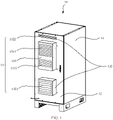
- the multi-temperature control cabinet 10 may include a cabinet body 11, one cabinet door 12, and a refrigerating system 13.
- the refrigerating system 13 includes one air conditioner 131, one direct ventilation unit 132, an air guide assembly 133 (shown in FIG. 2 ), and an environment monitoring apparatus (not shown in the figure).
- both the air conditioner 131 and the direct ventilation unit 132 are disposed on the cabinet door 12, and the air conditioner 131 and the direct ventilation unit 132 are disposed in parallel in a height direction of the cabinet door 12.
- the environment monitoring apparatus is connected to both the air conditioner 131 and the direct ventilation unit 132, and the environment monitoring apparatus is configured to: monitor temperature and humidity in the cabinet body 11, and control turning-on and turning-off of the air conditioner 131 and the direct ventilation unit 132 based on the temperature and the humidity in the cabinet body 11.
- the environment monitoring apparatus is disposed to monitor the temperature and the humidity in the cabinet 10, and control the turning-on and the turning-off of the direct ventilation unit 132 and the air conditioner 131 based on the temperature and the humidity in the cabinet 10, to ensure that both the temperature and the humidity in the cabinet 10 are in a relatively stable state, so that fluctuation of the humidity in the cabinet 10 is effectively avoided and condensation in the cabinet 10 can be avoided, thereby ensuring normal running of a device in the cabinet 10.
- FIG. 1 there may be one cabinet door 12.
- one or more air conditioners 131 and one or more direct ventilation units 132 may be disposed on the cabinet door 12.
- an example in which one air conditioner 131 and one direct ventilation unit 132 are disposed on the cabinet door 12 is specifically used for description.
- the cabinet body 11 of the multi-temperature control cabinet 10 is of a cuboid cabinet-like structure.
- the cabinet door 12 is rotatably disposed on one side of the cabinet body 11, the cabinet door 12 can be opened and closed relative to the cabinet body 11, and when the cabinet door 12 is in a closed state, the cabinet body 11 and the cabinet door 12 form closed space.
- An installation component for installing electrical equipment and the electrical equipment are disposed inside the cabinet body 11, and a specific position of the installation component is not specifically limited herein.
- the environment monitoring apparatus may be installed on the cabinet body 11, may be installed on the cabinet door 12, or may be installed on the installation component in the cabinet body 11, provided that the environment monitoring apparatus can monitor the temperature and the humidity in the cabinet 10 and can control the turning-on and the turning-off of the air conditioner 131 and the direct ventilation unit 132.
- the air conditioner 131 in this embodiment may be an integrated air conditioner.
- An air exhaust vent 1311 and an air return vent 1312 of the air conditioner 131 are disposed on the integrated air conditioner, and a side on which the air exhaust vent 1311 and the air return vent 1312 of the air conditioner 131 are disposed faces the inside of the cabinet body 11, to adjust the temperature inside the cabinet 10.
- a model of the integrated air conditioner is not limited herein, provided that the integrated air conditioner can conveniently adjust the temperature in the cabinet 10.
- the direct ventilation unit 132 includes an air intake unit 1321 and an air exhaust unit 1322.
- the air intake unit 1321 can suck natural air outside the cabinet 10 into the cabinet 10, and then the air is exhausted out of the cabinet 10 through the air exhaust unit 1322.
- the air intake unit 1321 is disposed below the air conditioner 131, and the air exhaust unit 1322 is disposed above the air conditioner 131. It should be noted that, because air rises due to thermal expansion, hot air is located above cold air in the cabinet 10.
- the disposing the air exhaust unit 1322 of the direct ventilation unit 132 above the air conditioner 131 helps exhaust the hot air in the cabinet 10 to the outside of the cabinet 10 through the air exhaust unit 1322, to implement exchange between air in the cabinet 10 and external air, thereby reducing the temperature in the cabinet 10 and balancing the humidity in the cabinet 10.
- the air guide assembly 133 is disposed between the direct ventilation unit 132 and the air exhaust vent 1311 of the air conditioner 131. Specifically, as shown in FIG. 2 , the air guide assembly 133 is disposed between the air intake unit 1321 and the air exhaust vent 1311 of the air conditioner 131.
- the air guide assembly 133 may be configured to mix cold air exhausted from the air exhaust vent 1311 of the air conditioner 131 with natural air entering from the air intake unit 1321, to balance humidity of the cold air exhausted from the air exhaust vent 1311 of the air conditioner 131.
- the air guide assembly 133 is disposed between the air intake unit 1321 and the air exhaust vent 1311 of the air conditioner 131, so that the cold air exhausted from the air exhaust vent 1311 of the air conditioner 131 can be mixed with the outdoor natural air entering from the air intake unit 1321, to adjust the humidity in the cabinet 10 when the temperature inside the cabinet 10 is adjusted, so that both the temperature and the humidity in the cabinet 10 are in a relatively stable state.
- This can ensure normal running of the device in the cabinet 10, can also decrease the temperature in the cabinet 10, and can further prevent fluctuation of the humidity in the cabinet 10, to reduce a risk of condensation.
- a dashed line with an arrow is used to represent a direction of an air path.
- an air path of the air conditioner 131 includes an air path located inside the cabinet 10 and an air path located outside the cabinet 10.
- the air path located inside the cabinet 10 is as follows: Natural air is sucked from an air intake vent 1313 of the air conditioner 131, and under a refrigeration action of the air conditioner 131, cold air is exhausted into the cabinet 10 from the air exhaust vent 1311 of the air conditioner 131.
- a part of the cold air reaches a lower part of the cabinet 10 through the air guide assembly 133, and a part of the cold air is directly exhausted into the cabinet 10 from the air exhaust vent 1311 of the air conditioner 131. Because the cold air enters the cabinet 10, hot air in the cabinet 10 rises. Therefore, a part of the hot air enters the air conditioner 131 from the air return vent 1312 of the air conditioner 131, and then is exhausted, or enters a next cold cycle.
- the air path outside the cabinet 10 is as follows: Natural air is sucked from the air intake vent 1313 of the air conditioner 131, and the natural air is exhausted from an air exhaust vent 1314 outside the cabinet of the air conditioner 131 after passing through a heat exchanger of the air conditioner 131.
- air paths of the air conditioner 131 and the direct ventilation unit 132 are as follows: Natural air is sucked from both the air intake vent 1313 of the air conditioner 131 and the air intake unit 1321 of the direct ventilation unit 132. After natural air sucked by the air conditioner 131 is processed, cold air is exhausted from the air exhaust vent 1311 of the air conditioner 131. A part of the cold air reaches the lower part of the cabinet 10 through the air guide assembly 133. Natural air sucked by the air intake unit 1321 directly enters the air guide assembly 133.
- the cold air exhausted from the air exhaust vent 1311 of the air conditioner 131 is mixed, in the air guide assembly 133, with the natural air sucked by the air intake unit 1321, and then mixed air is exhausted into the cabinet 10.
- an air path of the air conditioner 131 is mixed with an air path of the direct ventilation unit 132, to achieve an effect of air mixing between the air path of the air conditioner 131 and the air path of the direct ventilation unit 132.
- humidity of the cold air exhausted from the air conditioner 131 is relatively low, and humidity of the natural air entering from the direct ventilation unit 132 is relatively high
- humidity of the air exhausted into the cabinet 10 is relatively moderate, so that the humidity in the cabinet 10 is in a relatively moderate and relatively stable range. In this way, fluctuation of the humidity in the cabinet 10 can be prevented, to avoid condensation.
- the humidity of the cold air exhausted from the air exhaust vent 1311 of the air conditioner 131 is relatively low, and the humidity of the outdoor natural air sucked by the air intake unit 1321 is higher than the humidity of the cold air exhausted from the air conditioner 131. Therefore, the cold air exhausted from the air exhaust vent 1311 of the air conditioner 131 is mixed with the outdoor natural air sucked by the air intake unit 1321, so that the humidity in the cabinet 10 can be increased, to keep the humidity inside the cabinet 10 within a moderate range. Therefore, neither of the following cases occurs: Static electricity is caused in the cabinet 10 due to excessively low humidity, causing a damage to the device in the cabinet; and the device in the cabinet cannot normally work due to excessively high temperature. In addition, a risk of condensation caused due to fluctuation of the humidity inside the cabinet 10 can be further reduced.
- the turning-on and the turning-off of the air conditioner 131 and the direct ventilation unit 132 are controlled by using two indexes that are the temperature and the humidity, so that the humidity in the cabinet 10 can be adjusted when the temperature in the cabinet 10 is adjusted, and fluctuation of the humidity inside the cabinet 10 can also be prevented.
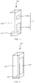
- two air intake vents 1331, an air mixing channel 1332, and one mixed-air exhaust vent 1333 are disposed on the air guide assembly 133.
- the two air intake vents 1331 are a first air intake vent 1331a and a second air intake vent 1331b.
- the first air intake vents 1331a is connected to the air exhaust vent 1311 of the air conditioner 131, and the second air intake vent 1331b is connected to the air intake unit 1321.
- the air guide assembly 133 in this embodiment is of a cuboid bucket-like structure. Both the first air intake vent 1331a and the second air intake vent 1331b are rectangular, and the mixed-air exhaust vent 1333 is circular.
- the first air intake vent 1331a and the second air intake vent 1331b are disposed on a same side of the air mixing channel 1332 and respectively correspond to the air exhaust vent 1311 of the air conditioner 131 and the air intake unit 1321 of the direct ventilation unit 132, and the mixed-air exhaust vent 1333 is disposed at a lower end of the air mixing channel 1332.
- the first air intake vent 1331a and the second air intake vent 1331b are rectangular in different sizes.
- a size of the first air intake vent 1331a is relatively small, and provided that the first air intake vent 1331a partially overlaps the air exhaust vent 1311 of the air conditioner 131, a part of cold air blown out of the air conditioner 131 can be guided into the air mixing channel 1332.
- the cold air blown out of the air conditioner 131 can be divided into two parts.
- a part of the cold air is directly blown into the cabinet 10 to facilitate quick cooling, and the other part of the cold air enters the air mixing channel 1332 to be mixed with natural air entering from the direct ventilation unit 132, to prevent a sudden decrease in the humidity inside the cabinet.
- a size of the second air intake vent 1331b is relatively large. In this way, more natural air can be guided into the air mixing channel 1332, so that humidity of air in the cabinet 10 can be quickly adjusted.
- the mixed-air exhaust vent 1333 is further disposed at the lower end of the air mixing channel 1332. The mixed-air exhaust vent 1333 may release mixed cold air with proper temperature and humidity into the cabinet 10, so that hot air inside the cabinet 10 rises, and then is exhausted out of the cabinet 10 from the air return vent 1312 of the air conditioner 131 and the air exhaust unit 1322 of the direct ventilation unit 132.
- first air intake vent 1331a and the second air intake vent 1331b may be in a same shape or different shapes, and the first air intake vent 1331a and the second air intake vent 1331b may be in a same size or different sizes.
- a specific shape and size may be specifically set based on a specific case, provided that the first air intake vent 1331a and the second air intake vent 1331b respectively correspond to the air exhaust vent 1311 of the air conditioner 131 and the air intake unit 1321 of the direct ventilation unit 132.
- the first air intake vent 1331a partially covers the air exhaust vent 1311 of the air conditioner 131.
- the first air intake vent 1331a may alternatively cover the entire air exhaust vent 1311 of the air conditioner 131. In this way, all cold air exhausted from the air exhaust vent 1311 of the air conditioner 131 can enter the air mixing channel 1332 to be fully mixed with natural air entering from the direct ventilation unit 132, and then mixed air can enter the cabinet 10 through the mixed-air exhaust vent 1333. In this way, it can be ensured that all air entering the cabinet 10 is obtained after air mixing processing, so that the humidity in the cabinet 10 is more easily kept in a relatively stable state, to effectively alleviate condensation in the cabinet 10.
- the second air intake vent 1331b may also partially cover the air intake unit 1321. In this way, air circulation in the cabinet 10 can be accelerated, to more quickly cool the cabinet 10.
- a first air intake vent 1331a, a second air intake vent 1331b, an air mixing channel 1332, and a mixed-air exhaust vent 1333 are disposed on the air guide assembly 133.
- the air guide assembly 133 is of a cuboid bucket-like structure as a whole, both the first air intake vent 1331a and the second air intake vent 1331b are rectangular, and the mixed-air exhaust vent 1333 is also rectangular.
- the first air intake vent 1331a and the second air intake vent 1331b are disposed on a same side of the air mixing channel 1332, the first air intake vent 1331a corresponds to the air exhaust vent 1311 of the air conditioner 131, the second air intake vent 1331b corresponds to the air intake unit 1321 of the direct ventilation unit 132, and the mixed-air exhaust vent 1333 is disposed on a side that is of the air mixing channel 1332 and that faces the inside of the cabinet 10.
- shapes of the air intake vents 1331 on the air guide assembly 133 are not limited to rectangles shown in FIG. 4 and FIG. 5 .
- the air intake vents 1331 may be alternatively in other shapes, for example, circular or trapezoidal, provided that the air mixing channel 1332 is connected to both the air intake vents 1331 and the mixed-air exhaust vent 1333 and the air intake vents 1331 are respectively connected to the air exhaust vent 1311 of the air conditioner 131 and the air intake unit 1321.
- a shape and a position of the mixed-air exhaust vent 1333 may be specifically set based on a specific case.
- the mixed-air exhaust vent 1333 may be of a circular structure and disposed at the lower end of the air mixing channel 1332, as shown in FIG. 4 , or the mixed-air exhaust vent 1333 may be of a rectangular structure and disposed on the side that is of the air guide channel and that faces the inside of the cabinet 10, as shown in FIG. 5 .
- a length and a shape of the air guide channel are not specifically limited herein. Provided that there is an air guide channel and cold air blown out of the air conditioner 131 can be mixed with natural air entering from the direct ventilation unit 132, this falls within the protection scope of the technical solutions of this application.
- one air intake vent 1331, an air mixing channel 1332, and one mixed-air exhaust vent 1333 are disposed on the air guide assembly 133.
- the air guide assembly 133 is of a cuboid bucket-like structure as a whole, the air intake vent 1331 is rectangular, and the mixed-air exhaust vent 1333 is also rectangular.
- the air intake vent 1331 is disposed on a side that is of the air mixing channel 1332 and that faces the cabinet door 12, the air intake vent 1331 is connected to both the air exhaust vent 1311 of the air conditioner 131 and the air exhaust unit 1322, and the mixed-air exhaust vent 1333 is circular and is disposed at a lower end of the air mixing channel 1332.
- the air intake vent 1331 is disposed as a large rectangular structure, so that a structure of the air guide assembly 133 can be simplified, and mixing of cold air blown out of the air conditioner 131 and natural air entering from the direct ventilation unit 132 can be accelerated, to more quickly adjust the temperature and the humidity in the cabinet 10, thereby ensuring normal running of the device in the cabinet 10.
- an overall shape of the air guide assembly 133 is not limited to the cuboid bucket-like structure, and alternatively, may be of a circular tubular structure or may be of another odd-form structure. Provided that an air mixing effect can be implemented, this falls within the protection scope of the technical solutions of this application.
- a material of the air guide assembly 133 includes but is not limited to sheet metal or plastic, and may be alternatively another material such as rubber.
- a fastening manner of the air guide assembly 133 does not constitute a limitation on the protection scope of the technical solutions of this application, provided that the air guide assembly 133 can be fastened to the cabinet door 12.
- the environment monitoring apparatus may include a temperature monitoring component and a humidity monitoring component.
- the temperature monitoring part is configured to monitor the temperature in the cabinet body 11.
- the humidity monitoring unit is configured to monitor the humidity in the cabinet body 11.
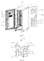
- a cabinet door 12 in this embodiment includes a first cabinet door 121 and a second cabinet door 122 that are oppositely disposed; one air conditioner 131 and an air intake unit 1321 are disposed on the first cabinet door 121, and the air intake unit 1321 is located below the air conditioner 131; one air conditioner 131 and an air exhaust unit 1322 are disposed on the second cabinet door 122, and the air exhaust unit 1322 is located above the air conditioner 131; and an air guide assembly 133 is disposed between an air exhaust vent 1311 of the air conditioner 131 and the air intake unit 1321 on the first cabinet door 121.
- the air conditioner 131 and the air intake unit 1321 are disposed on the first cabinet door 121, and the air conditioner 131 is located above the air intake unit 1321; and the air conditioner 131 and the air exhaust unit 1322 are disposed on the second cabinet door 122, and the air conditioner 131 is located below the air exhaust unit 1322.
- the air conditioners 131 on the two cabinet doors 12 are located at different heights
- the air intake unit 1321 and the air exhaust unit 1322 are also located at different heights
- the two air conditioners 131, the air intake unit 1321, and the air exhaust unit 1322 are respectively located in four positions of a cabinet 10, so that convection is caused during refrigeration of the cabinet 10, to accelerate adjustment of temperature and humidity in the cabinet 10. As shown in FIG.
- an air path of the air conditioner 131 disposed on the first cabinet door 121 includes an air path located inside the cabinet 10 and an air path located outside the cabinet 10.
- the air path located inside the cabinet 10 is as follows: Natural air is sucked from an air intake vent 1313 of the air conditioner 131, and under a refrigeration action of the air conditioner 131, cold air is exhausted into the cabinet 10 from the air exhaust vent 1311 of the air conditioner 131. A part of the cold air reaches a lower part of the cabinet 10 through the air guide assembly 133, a part of the cold air is directly exhausted into the cabinet 10 from the air exhaust vent 1311 of the air conditioner 131, and a part of air in the cabinet 10 is exhausted through an air return vent 1312 of the air conditioner 131.
- An air path of the air conditioner 131 disposed on the second cabinet door 122 is as follows: Natural air is sucked from an air intake vent 1313 of the air conditioner 131, and under a refrigeration action of the air conditioner 131, cold air is exhausted into the cabinet 10 from an air exhaust vent 1311 of the air conditioner 131. A part of air in the cabinet 10 is exhausted through an air return vent 1312 of the air conditioner 131.
- the air path outside the cabinet 10 is as follows: Natural air is sucked from the air intake vent 1313 of the air conditioner 131, and the natural air is exhausted from an air exhaust vent 1314 outside the cabinet of the air conditioner 131 after passing through a heat exchanger of the air conditioner 131.
- the air conditioner 131 on the first cabinet door 121 is disposed above the air intake unit 1321
- the air conditioner 131 on the second cabinet door 122 is disposed below the air exhaust unit 1322, and the two cabinet doors 12 are oppositely disposed, during working, the two air conditioners 131 blow cold air to each other in opposite directions. In this way, convection of the cabinet 10 is enhanced, to accelerate air circulation in the cabinet 10, thereby accelerating refrigeration inside the cabinet 10.
- air paths of the air conditioners 131 and the direct ventilation unit 132 are as follows: Both the air intake vents 1313 of the two air conditioners 131 and the air intake unit 1321 of the direct ventilation unit 132 suck natural air. After natural air sucked by the air conditioners 131 is processed, cold air is exhausted from the air exhaust vents 1311 of the air conditioners 131.
- a part of cold air generated by the air conditioner 131 located on the first cabinet door 121 reaches the lower part of the cabinet 10 through the air guide assembly 133, and natural air sucked by the air intake unit 1321 directly enters the air guide assembly 133.
- cold air exhausted from the air exhaust vent 1311 of the air conditioner 131 on the first cabinet door 121 is mixed, in the air guide assembly 133, with the natural air sucked by the air intake unit 1321, and then mixed air is exhausted into the cabinet 10 from a mixed-air exhaust vent 1333 of the air guide assembly 133.
- Cold air generated by the air conditioner 131 located on the second cabinet door 122 is directly exhausted into the cabinet 10 from the air exhaust vent 1311 of the air conditioner 131.
- both the air conditioner 131 on the second cabinet door 122 and the mixed-air exhaust vent 1333 of the air guide assembly 133 are located in the lower part of the cabinet 10, the air blown out of the air conditioner 131 on the second cabinet door 122 is mixed with the mixed air exhausted from the air guide assembly 133, and then a part of air in the cabinet 10 is exhausted out of the cabinet 10 through the air return vent 1312 of the air conditioner 131 and the air exhaust unit 1322.
- Humidity of cold air exhausted from the air conditioner 131 is relatively low, and humidity of natural air entering from the direct ventilation unit 132 is relatively high, and after the cold air blown out of the air conditioner 131 is mixed with the natural air, the humidity in the cabinet 10 is in a relatively moderate and relatively stable range. In this way, fluctuation of the humidity in the cabinet 10 can be prevented, to avoid condensation.
- an air guide assembly 133 may be further disposed between the air exhaust vent 1311 of the air conditioner 131 on the second cabinet door 122 and the air intake unit 1321. It should be noted that when the air guide assembly 133 is disposed between the air exhaust vent 1311 of the air conditioner 131 on the second cabinet door 122 and the air intake unit 1321, because the air intake unit 1321 is disposed on the first cabinet door, the air guide assembly 133 may be disposed on a lower part of the cabinet body in this case.
- a first air intake vent 1331a of the air guide assembly 133 exactly corresponds to the air exhaust vent 1311 of the air conditioner 131
- a second air intake vent 1331b of the air guide assembly 133 exactly corresponds to the air intake unit 1321.
- the first air intake vent 1331a and the second air intake vent 1331b may be disposed on two ends of the air guide assembly 133. In this way, when the two cabinet doors are closed, it can be ensured that the two air intake vents 1331 respectively correspond to the air conditioner 131 and the air intake unit 1321.
- a mixed-air exhaust vent 1333 may be disposed on a side that is of the air guide assembly 133 and that is close to the top of the cabinet 10. In this way, mixed air of the air conditioner 131 and the direct ventilation unit 132 can be blown into the cabinet 10.
- the two air guide assemblies 133 may be in a same shape or different shapes, provided that an air mixing effect can be implemented.
- an embodiment provides a scheduling method for a multi-temperature control cabinet 10.
- the method may include: an environment monitoring apparatus performs real-time monitoring on temperature and humidity in a cabinet body 11; and controls turning-on and turning-off of an air conditioner 131 and a direct ventilation unit 132 based on monitored temperature and humidity values.
- the temperature in the cabinet 10 may include three cases. In a first case, the temperature in the cabinet is relatively high, for example, exceeds a first preset temperature threshold. In a second case, the temperature in the cabinet falls between the first preset temperature threshold and a second preset temperature threshold. In a third case, the temperature in the cabinet is lower than the second preset temperature threshold. For the first case and the second case, a refrigerating system 13 is usually used for adjustment. For the third case, no adjustment may be performed.
- the following describes in detail a process of adjusting the temperature and the humidity in the cabinet when the temperature in the cabinet 10 is in the first case.
- the controlling turning-on and turning-off of an air conditioner 131 and a direct ventilation unit 132 based on monitored temperature and humidity values may include: determining whether the temperature monitored by the environment monitoring apparatus is higher than the first preset temperature threshold; when the temperature monitored by the environment monitoring apparatus is higher than the first preset temperature threshold, turning on the air conditioner 131; when the air conditioner 131 is in a working state, determining whether humidity monitored by the environment monitoring apparatus is lower than a first preset humidity threshold; and when the humidity monitored by the environment monitoring apparatus is lower than the first preset humidity threshold, turning on the direct ventilation unit 132, so that the direct ventilation unit 132 and the air conditioner 131 increase the humidity in the cabinet in an air mixing manner.
- the method may further include: determining whether a difference between humidity monitored by the environment monitoring apparatus in a first preset time period is lower than a first preset difference; and when the difference between the humidity monitored by the environment monitoring apparatus in the first preset time period is lower than the first preset difference, turning off the direct ventilation unit 132.
- the method may further include: determining whether humidity monitored by the environment monitoring apparatus is higher than a second preset humidity threshold, where the first preset humidity threshold is smaller than the second preset humidity threshold; and when the humidity monitored by the environment monitoring apparatus is higher than the second preset humidity threshold, turning off the direct ventilation unit 132.
- the air conditioner 131 mainly runs to adjust the temperature and the humidity inside the cabinet 10.
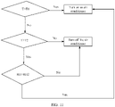
- the method may further include: determining whether temperature monitored by the environment monitoring apparatus is lower than the second preset temperature threshold, where the second preset temperature threshold is lower than the first preset temperature threshold; and when the temperature monitored by the environment monitoring apparatus is lower than the second preset temperature threshold, turning off the air conditioner 131.
- a preset temperature threshold is represented by T
- the first preset temperature threshold is represented by T1
- the second preset temperature threshold is represented by T2
- a preset humidity threshold is represented by RH
- a first preset humidity threshold is represented by RH1
- a second preset humidity threshold is represented by RH2
- a preset difference is represented by a, the first preset difference is represented by a1, and a second preset difference is represented by a2.
- both the first preset time period and a second preset time period are 30 min.
- the environment monitoring apparatus when determining, through monitoring, that temperature in the cabinet 10 is higher than T1 at a specific moment, the environment monitoring apparatus turns on the air conditioner 131 to perform refrigeration; when humidity monitored by the monitoring apparatus is lower than RH1, the environment monitoring apparatus turns on the direct ventilation unit 132, so that the direct ventilation unit 132 and the air conditioner 131 increase the humidity in the cabinet in an air mixing manner; and after the air conditioner 131 and the direct ventilation unit 132 work for a period of time, the temperature in the cabinet 10 decreases and the humidity in the cabinet 10 increases, and when a difference between humidity monitored by the environment monitoring apparatus in 30 min is lower than a1, that is, humidity is in a stable state, the environment monitoring apparatus turns off the direct ventilation unit 132.
- the direct ventilation unit 132 when the direct ventilation unit 132 is in an on state, when humidity monitored by the environment monitoring apparatus is greater than RH2, the direct ventilation unit 132 is turned off.
- the air conditioner 131 mainly runs to adjust the temperature and the humidity inside the cabinet 10.
- the air conditioner 131 is turned off.
- the following describes in detail a process of adjusting the temperature and the humidity in the cabinet when the temperature in the cabinet 10 is in the second case.
- the controlling turning-on and turning-off of an air conditioner 131 and a direct ventilation unit 132 based on monitored temperature and humidity values may alternatively include: determining whether the temperature monitored by the environment monitoring apparatus is lower than the first preset temperature threshold and higher than the second preset temperature threshold; and when the temperature monitored by the environment monitoring apparatus is lower than the first preset temperature threshold and higher than the second preset temperature threshold, turning on the direct ventilation unit 132, to cool the inside of the cabinet 10 by using the direct ventilation unit 132.
- the method may further include: determining whether a difference between humidity monitored by the environment monitoring apparatus in the first preset time period is lower than the first preset difference; and when the difference between the humidity monitored by the environment monitoring apparatus in the first preset time period is lower than the first preset difference, turning off the direct ventilation unit 132.
- the method may further include: determining whether humidity monitored by the environment monitoring apparatus is higher than the second preset humidity threshold, where the first preset humidity threshold is smaller than the second preset humidity threshold; and when the humidity monitored by the environment monitoring apparatus is higher than the second preset humidity threshold, turning on an internal circulation fan of the air conditioner 131, to decrease the humidity in the cabinet in an air mixing manner by using the direct ventilation unit 132 and the air conditioner 131.
- the method may further include: determining whether a difference between humidity monitored by the environment monitoring apparatus in the second preset time period is lower than the second preset difference; and when the difference between the humidity monitored by the environment monitoring apparatus in the second preset time period is lower than the second preset difference, turning off the air conditioner 131.
- the environment monitoring apparatus when determining, through monitoring, that temperature in the cabinet 10 is lower than T1 and higher than T2 at a specific moment, the environment monitoring apparatus turns on the direct ventilation unit 132 to perform refrigeration; and after the direct ventilation unit 132 works for a period of time, the humidity in the cabinet 10 increases, and when a difference between humidity monitored by the environment monitoring apparatus in the first preset time period is lower than a1, that is, humidity is in a stable state, the environment monitoring apparatus turns off the direct ventilation unit 132.
- the direct ventilation unit 132 when the direct ventilation unit 132 is in an on state, when humidity monitored by the environment monitoring apparatus is greater than RH2, an internal circulation fan of the air conditioner 131 is turned on; and when a difference between humidity monitored by the environment monitoring apparatus in the second preset time period is lower than a2, that is, humidity is in a stable state, the air conditioner 131 is turned off.
- the internal circulation fan of the air conditioner 131 is located inside the cabinet 10.
- the internal circulation fan can enable air in the cabinet to be sequentially circulated, so that hot air in the cabinet 10 can be sequentially blown into the air conditioner 131 for heat exchange.
- humidity of the air is decreased due to refrigeration of the air conditioner 131.
- the first preset time period may be the same as or may be different from the second preset time period.
- the first preset difference may be the same as or may be different from the second preset difference.
- the air conditioner 131 when the temperature is higher than T1, or the temperature falls between T1 and T2 and the humidity is greater than RH2, the air conditioner 131 may be turned on; or when the temperature is not greater than T2, or the temperature falls between T1 and T2 and the humidity is not greater than RH2, the air conditioner 131 may be turned off.
- the direct ventilation unit 132 when the temperature is smaller than T2, or the temperature is not smaller than T1 and the humidity is greater than RH1, the direct ventilation unit 132 may be turned off; or when the humidity is not greater than RH1, or the temperature falls between T1 and T2, the direct ventilation unit 132 may be turned on.
- the turning-on and the turning-off of the air conditioner 131 and the direct ventilation unit 132 are controlled by using two indexes that are the temperature and the humidity, so that the humidity in the cabinet 10 can be adjusted when the temperature in the cabinet 10 is adjusted, and fluctuation of the humidity inside the cabinet 10 can also be prevented, to avoid condensation inside the cabinet.
- the method may further include: determining whether temperature monitored by the environment monitoring apparatus is lower than the second temperature threshold, and determining whether a difference between humidity monitored by the environment monitoring apparatus in the first preset time period is lower than the first preset difference; when the temperature monitored by the environment monitoring apparatus is lower than the second temperature threshold, and the difference between the humidity monitored by the environment monitoring apparatus in the first preset time period is lower than the first preset difference, turning off the air conditioner 131, and also turning off the direct ventilation unit 132.
- the temperature and humidity in the cabinet 10 are in a proper state and do not need to be adjusted.
- only the direct ventilation unit 132 may be turned on to adjust an internal environment of the cabinet 10, so that the internal environment of the cabinet 10 is kept in a proper state.
- the air conditioner 131 is turned on again, and the temperature and humidity in the cabinet 10 are adjusted according to the adjustment steps used when the temperature in the cabinet 10 is in the first case.
Abstract
Description
- The present invention relates to the field of cabinet technologies, and in particular, to a multi-temperature control cabinet and a scheduling method for a multi-temperature control cabinet.
- A cabinet is a freestanding or self-supporting housing that accommodates electrical or electronic equipment. A door, a removable or non-removable side panel, and a backplane are usually configured for the cabinet. The cabinet is an indispensable component of electrical equipment and is a carrier of electrical control equipment. The cabinet is usually made of a cold-rolled steel plate or an alloy, and can provide protection functions such as waterproof, dustproof, and electromagnetic interference prevention for a stored device. In addition, to ensure that the device in the cabinet can run in a good environment, a temperature adjustment system is disposed in the cabinet to ensure that the device in the cabinet can run in a stable environment.
- In the conventional technology, an air conditioner and direct ventilation are disposed in a cabinet to adjust temperature in the cabinet. Both the air conditioner and the direct ventilation are connected to a temperature control component. The temperature control component is configured to: monitor the temperature in the cabinet, and control turning-on and turning-off of the air conditioner and the direct ventilation by using the temperature in the cabinet. Specifically, when the temperature in the cabinet is relatively high, the air conditioner starts to run, and the direct ventilation does not run; or when the temperature in the cabinet is relatively low, the air conditioner is turned off, and the direct ventilation starts to work, to adjust the temperature in the cabinet.
- However, the controlling the turning-on and the turning-off of the air conditioner and the direct ventilation by using the temperature control component causes fluctuation of humidity in the cabinet, and in a serious case, causes a high-humidity alarm and condensation of a device in the cabinet.
- Embodiments of this application provide a multi-temperature control cabinet and a scheduling method for a multi-temperature control cabinet, to resolve a technical problem that condensation is likely to be caused due to fluctuation of humidity in the cabinet.
- A first aspect of embodiments of this application provides a multi-temperature control cabinet, including a cabinet body, a cabinet door, and a refrigerating system.
- The refrigerating system includes at least one air conditioner, at least one direct ventilation unit, and an environment monitoring apparatus.
- Both the air conditioner and the direct ventilation unit are disposed on the cabinet door, and the air conditioner and the direct ventilation unit are disposed in parallel in a height direction of the cabinet door.
- An air guide assembly is disposed between the direct ventilation unit and an air exhaust vent of the air conditioner.
- The environment monitoring apparatus is connected to both the air conditioner and the direct ventilation unit, and the environment monitoring apparatus is configured to: monitor temperature and humidity in the cabinet body, and control turning-on and turning-off of the air conditioner and the direct ventilation unit based on the temperature and the humidity in the cabinet body.
- According to the multi-temperature control cabinet provided in this embodiment of this application, the air conditioner, the direct ventilation unit, and the environment monitoring apparatus are disposed, and the turning-on and the turning-off of the air conditioner and the direct ventilation unit are jointly controlled by using the temperature and the humidity that are monitored by the environment monitoring apparatus. Therefore, ranges of the humidity and the temperature inside the cabinet can be accurately controlled, so that condensation caused when the cabinet door is opened can be alleviated and frequent high-humidity or low-humidity alarms in the cabinet can be reduced, thereby reducing site maintenance frequency and reducing maintenance costs.
- As an explanation, when the humidity in the cabinet is excessively high, a device inside the cabinet is corroded, and condensation is likely to be caused when the door is opened; or when the humidity in the cabinet is excessively low, static electricity is likely to be caused, and the device in the cabinet is damaged due to electrostatic discharge, affecting normal running of the cabinet. However, when the air conditioner is used to adjust the temperature in the cabinet, the humidity in the cabinet fluctuates. In this way, frequent high-humidity or low-humidity alarms are caused in the cabinet, and further a specific risk is brought to normal running of the cabinet. Therefore, proper humidity is also an important indicator for ensuring normal running of the cabinet.
- In a possible implementation, the direct ventilation unit includes an air intake unit and an air exhaust unit.
- The air guide assembly is disposed between the air intake unit and the air exhaust vent of the air conditioner.
- In a possible implementation, there is one cabinet door.
- The air intake unit is located below the air conditioner.
- The air exhaust unit is disposed above the air conditioner.
- In a possible implementation, the cabinet door includes a first cabinet door and a second cabinet door that are oppositely disposed.
- One air conditioner and the air intake unit are disposed on the first cabinet door, and the air intake unit is located below the air conditioner.
- One air conditioner and the air exhaust unit are disposed on the second cabinet door, and the air exhaust unit is located above the air conditioner.
- The air guide assembly is disposed between an air exhaust vent of the air conditioner and the air intake unit on the first cabinet door.
- In a possible implementation, an air intake vent, an air mixing channel, and a mixed-air exhaust vent are disposed on the air guide assembly.
- The air mixing channel is connected to both the air intake vent and the mixed-air exhaust vent.
- The air intake vent is connected to both the air exhaust vent of the air conditioner and the air intake unit.
- In a possible implementation, the air guide assembly is of a barrel-like structure.
- The air intake vent includes a first air intake vent and a second air intake vent.
- The first air intake vent is connected to the air exhaust vent of the air conditioner.
- The second air intake vent is connected to the air intake unit.
- In a possible implementation, a material of the air guide assembly is sheet metal or plastic.
- In a possible implementation, the environment monitoring apparatus includes a temperature monitoring component and a humidity monitoring component.
- The temperature monitoring component is configured to monitor the temperature in the cabinet body.
- The humidity monitoring component is configured to monitor the humidity in the cabinet body.
- A second aspect of this application provides a scheduling method for a multi-temperature control cabinet, used to adjust temperature and humidity in the foregoing multi-temperature control cabinet. The method includes:
- performing, by an environment monitoring apparatus, real-time monitoring on temperature and humidity in a cabinet body; and
- controlling turning-on and turning-off of an air conditioner and a direct ventilation unit based on monitored temperature and humidity values.
- In a possible implementation, the controlling turning-on and turning-off of an air conditioner and a direct ventilation unit based on monitored temperature and humidity values includes:
- determining whether the temperature monitored by the environment monitoring apparatus is higher than a first preset temperature threshold;
- when the temperature monitored by the environment monitoring apparatus is higher than the first preset temperature threshold, turning on the air conditioner;
- when the air conditioner is in a working state, determining whether humidity monitored by the environment monitoring apparatus is lower than a first preset humidity threshold; and
- when the humidity monitored by the environment monitoring apparatus is lower than the first preset humidity threshold, turning on the direct ventilation unit, so that the direct ventilation unit and the air conditioner increase the humidity in the cabinet in an air mixing manner.
- In a possible implementation, the controlling turning-on and turning-off of an air conditioner and a direct ventilation unit based on monitored temperature and humidity values includes:
- determining whether the temperature monitored by the environment monitoring apparatus is lower than the first preset temperature threshold and higher than a second preset temperature threshold, where the second preset temperature threshold is lower than the first preset temperature threshold; and
- when the temperature monitored by the environment monitoring apparatus is lower than the first preset temperature threshold and higher than the second preset temperature threshold, turning on the direct ventilation unit, to adjust air in the cabinet by using the direct ventilation unit.
- In a possible implementation, after the turning on the direct ventilation unit, the method further includes:
- determining whether a difference between humidity monitored by the environment monitoring apparatus in a first preset time period is lower than a first preset difference; and
- when the difference between the humidity monitored by the environment monitoring apparatus in the first preset time period is lower than the first preset difference, turning off the direct ventilation unit.
- In a possible implementation, after the turning on the direct ventilation unit, the method further includes:
- determining whether humidity monitored by the environment monitoring apparatus is higher than a second preset humidity threshold, where the first preset humidity threshold is smaller than the second preset humidity threshold; and
- when the humidity monitored by the environment monitoring apparatus is higher than the second preset humidity threshold, turning off the direct ventilation unit, to decrease the humidity in the cabinet through running of the air conditioner.
- In a possible implementation, after the turning off the direct ventilation unit, the method further includes:
- determining whether temperature monitored by the environment monitoring apparatus is lower than a second preset temperature threshold, where the second preset temperature threshold is lower than the first preset temperature threshold; and
- when the temperature monitored by the environment monitoring apparatus is lower than the second preset temperature threshold, turning off the air conditioner;
- In a possible implementation, after the turning on the direct ventilation unit, the method further includes:
- determining whether humidity monitored by the environment monitoring apparatus is higher than a second preset humidity threshold, where the first preset humidity threshold is smaller than the second preset humidity threshold; and
- when the humidity monitored by the environment monitoring apparatus is higher than the second preset humidity threshold, turning on an internal circulation fan of the air conditioner, to decrease the humidity in the cabinet in an air mixing manner by using the direct ventilation unit and the air conditioner.
- In a possible implementation, after the turning on an internal circulation fan of the air conditioner, the method further includes:
- determining whether a difference between humidity monitored by the environment monitoring apparatus in a second preset time period is lower than a second preset difference; and
- when the difference between the humidity monitored by the environment monitoring apparatus in the second preset time period is lower than the second preset difference, turning off the air conditioner.
-
-
FIG. 1 is a schematic diagram of a three-dimensional structure of a multi-temperature control cabinet according to an embodiment of this application; -
FIG. 2 is a schematic diagram of a structure of an open state of a cabinet door of a multi-temperature control cabinet according to an embodiment of this application; -
FIG. 3 is a schematic diagram of an air path of a multi-temperature control cabinet according to an embodiment of this application; -
FIG. 4 is a schematic diagram of a structure of an air guide assembly of a multi-temperature control cabinet according to an embodiment of this application; -
FIG. 5 is a schematic diagram of another structure of an air guide assembly of a multi-temperature control cabinet according to an embodiment of this application; -
FIG. 6 is a schematic diagram of still another structure of an air guide assembly of a multi-temperature control cabinet according to an embodiment of this application; -
FIG. 7 is a schematic diagram of a structure of an open state of a cabinet door of a multi-temperature control cabinet according to another embodiment of this application; -
FIG. 8 is a schematic diagram of an air path of a multi-temperature control cabinet according to another embodiment of this application; -
FIG. 9 is a working flowchart of an air scheduling method for a multi-temperature control cabinet according to an embodiment of this application; -
FIG. 10 is another working flowchart of an air scheduling method for a multi-temperature control cabinet according to an embodiment of this application; -
FIG. 11 is a working flowchart of an air conditioner in an air scheduling method for a multi-temperature control cabinet according to an embodiment of this application; and -
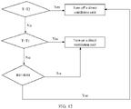
FIG. 12 is a working flowchart of a direct ventilation unit in an air scheduling method for a multi-temperature control cabinet according to an embodiment of this application. - Description of reference numerals:
- 10-cabinet; 11-cabinet body; 12-cabinet door; and 121-first cabinet door;
- 122-second cabinet door; 13-refrigerating system; 131-air conditioner; and 1311-air exhaust vent;
- 1312-air return vent; 1313-air intake vent; and 1314-air exhaust vent outside the cabinet;
- 132-direct ventilation unit; 1321-air intake unit; 1322-air exhaust unit; and 133-air guide assembly;
- 1331-air intake vent; 133 1a-first air intake vent; 1331b-second air intake vent; and 1332-air mixing channel; and
- 1333-mixed-air exhaust vent.
- An embodiment of this application provides a multi-temperature control cabinet. The multi-temperature control cabinet is used as an outdoor power cabinet, an outdoor device cabinet, an indoor device cabinet, an indoor power cabinet, or the like.
- An embodiment of this application provides a multi-temperature control cabinet. The multi-temperature control cabinet can adjust temperature and humidity in the cabinet, so that it can be ensured that a device in the cabinet can normally run in a proper temperature range. In addition, the multi-temperature control cabinet can further adjust the humidity in the cabinet, to resolve fluctuation of the humidity in the cabinet that is caused due to temperature adjustment.
- It should be noted that when the humidity in the cabinet is excessively high, the device in the cabinet is corroded; or when the humidity in the cabinet is excessively low, static electricity is caused, and the device in the cabinet is damaged due to electrostatic discharge. In addition, fluctuation of the humidity in the cabinet causes a high-humidity or low-humidity alarm and even causes condensation in the cabinet.
- In the conventional technology, an air conditioner is usually installed in a cabinet, and temperature is used as a parameter for controlling turning-on and turning off of the air conditioner. However, the cabinet is relatively sealed space. When the air conditioner is used to adjust temperature, humidity in the cabinet changes. Specifically, after the air conditioner is turned on for a period of time, both the temperature and the humidity in the cabinet decrease. When the temperature decreases to a preset temperature, the air conditioner is turned off. In this adjustment manner, the air conditioner needs to be frequently turned on and turned off. This improves energy consumption; and also causes fluctuation of the humidity in the cabinet, and in a serious case, causes a high-humidity alarm and condensation of a device in the cabinet.
- In addition, there is a method in which two types of devices that are an air conditioner and direct ventilation are installed in a cabinet to adjust temperature in the cabinet. Specifically, when the temperature is relatively high, the temperature in the cabinet is adjusted by turning on the air conditioner and turning off the direct ventilation; or when the temperature is relatively low, the temperature in the cabinet is adjusted by turning off the air conditioner and turning on the direct ventilation. However, when the direct ventilation is turned off and the air conditioner is turned on, the temperature in the cabinet quickly increases; or when the air conditioner is turned off and the direct ventilation is turned on, humidity in the cabinet quickly increases. In addition, this case frequently happens in a process of adjusting the temperature in the cabinet. In this way, condensation is likely to be caused, and in a serious case, normal running of a device in the cabinet is affected.
- To resolve the foregoing problem, embodiments provide a multi-temperature control cabinet, to resolve a technical problem that condensation is likely to be caused due to fluctuation of humidity in the cabinet.
- As shown in
FIG. 1 , this embodiment provides amulti-temperature control cabinet 10. Themulti-temperature control cabinet 10 may include acabinet body 11, onecabinet door 12, and arefrigerating system 13. The refrigeratingsystem 13 includes oneair conditioner 131, onedirect ventilation unit 132, an air guide assembly 133 (shown inFIG. 2 ), and an environment monitoring apparatus (not shown in the figure). Specifically, both theair conditioner 131 and thedirect ventilation unit 132 are disposed on thecabinet door 12, and theair conditioner 131 and thedirect ventilation unit 132 are disposed in parallel in a height direction of thecabinet door 12. The environment monitoring apparatus is connected to both theair conditioner 131 and thedirect ventilation unit 132, and the environment monitoring apparatus is configured to: monitor temperature and humidity in thecabinet body 11, and control turning-on and turning-off of theair conditioner 131 and thedirect ventilation unit 132 based on the temperature and the humidity in thecabinet body 11. In this embodiment of this application, the environment monitoring apparatus is disposed to monitor the temperature and the humidity in thecabinet 10, and control the turning-on and the turning-off of thedirect ventilation unit 132 and theair conditioner 131 based on the temperature and the humidity in thecabinet 10, to ensure that both the temperature and the humidity in thecabinet 10 are in a relatively stable state, so that fluctuation of the humidity in thecabinet 10 is effectively avoided and condensation in thecabinet 10 can be avoided, thereby ensuring normal running of a device in thecabinet 10. - In this embodiment of this application, as shown in
FIG. 1 , there may be onecabinet door 12. Certainly, in some examples, there may be a plurality ofcabinet doors 12. One ormore air conditioners 131 and one or moredirect ventilation units 132 may be disposed on thecabinet door 12. In this embodiment of this application, an example in which oneair conditioner 131 and onedirect ventilation unit 132 are disposed on thecabinet door 12 is specifically used for description. - As shown in
FIG. 1 , thecabinet body 11 of themulti-temperature control cabinet 10 is of a cuboid cabinet-like structure. Thecabinet door 12 is rotatably disposed on one side of thecabinet body 11, thecabinet door 12 can be opened and closed relative to thecabinet body 11, and when thecabinet door 12 is in a closed state, thecabinet body 11 and thecabinet door 12 form closed space. An installation component for installing electrical equipment and the electrical equipment are disposed inside thecabinet body 11, and a specific position of the installation component is not specifically limited herein. - It should be noted that the environment monitoring apparatus may be installed on the
cabinet body 11, may be installed on thecabinet door 12, or may be installed on the installation component in thecabinet body 11, provided that the environment monitoring apparatus can monitor the temperature and the humidity in thecabinet 10 and can control the turning-on and the turning-off of theair conditioner 131 and thedirect ventilation unit 132. - It should be noted that the
air conditioner 131 in this embodiment may be an integrated air conditioner. An air exhaust vent 1311 and anair return vent 1312 of theair conditioner 131 are disposed on the integrated air conditioner, and a side on which the air exhaust vent 1311 and theair return vent 1312 of theair conditioner 131 are disposed faces the inside of thecabinet body 11, to adjust the temperature inside thecabinet 10. A model of the integrated air conditioner is not limited herein, provided that the integrated air conditioner can conveniently adjust the temperature in thecabinet 10. - In a further embodiment of this application, as shown in
FIG. 1 andFIG. 2 , thedirect ventilation unit 132 includes anair intake unit 1321 and anair exhaust unit 1322. Theair intake unit 1321 can suck natural air outside thecabinet 10 into thecabinet 10, and then the air is exhausted out of thecabinet 10 through theair exhaust unit 1322. - In this embodiment of this application, the
air intake unit 1321 is disposed below theair conditioner 131, and theair exhaust unit 1322 is disposed above theair conditioner 131. It should be noted that, because air rises due to thermal expansion, hot air is located above cold air in thecabinet 10. The disposing theair exhaust unit 1322 of thedirect ventilation unit 132 above theair conditioner 131 helps exhaust the hot air in thecabinet 10 to the outside of thecabinet 10 through theair exhaust unit 1322, to implement exchange between air in thecabinet 10 and external air, thereby reducing the temperature in thecabinet 10 and balancing the humidity in thecabinet 10. - The
air guide assembly 133 is disposed between thedirect ventilation unit 132 and the air exhaust vent 1311 of theair conditioner 131. Specifically, as shown inFIG. 2 , theair guide assembly 133 is disposed between theair intake unit 1321 and the air exhaust vent 1311 of theair conditioner 131. Theair guide assembly 133 may be configured to mix cold air exhausted from the air exhaust vent 1311 of theair conditioner 131 with natural air entering from theair intake unit 1321, to balance humidity of the cold air exhausted from the air exhaust vent 1311 of theair conditioner 131. - The
air guide assembly 133 is disposed between theair intake unit 1321 and the air exhaust vent 1311 of theair conditioner 131, so that the cold air exhausted from the air exhaust vent 1311 of theair conditioner 131 can be mixed with the outdoor natural air entering from theair intake unit 1321, to adjust the humidity in thecabinet 10 when the temperature inside thecabinet 10 is adjusted, so that both the temperature and the humidity in thecabinet 10 are in a relatively stable state. This can ensure normal running of the device in thecabinet 10, can also decrease the temperature in thecabinet 10, and can further prevent fluctuation of the humidity in thecabinet 10, to reduce a risk of condensation. In a further embodiment of this application, as shown inFIG. 3 , a dashed line with an arrow is used to represent a direction of an air path. During actual application, when determining, through monitoring, that the temperature inside thecabinet 10 is relatively high, the environment monitoring apparatus turns on theair conditioner 131 to perform refrigeration processing inside thecabinet 10. In this case, an air path of theair conditioner 131 includes an air path located inside thecabinet 10 and an air path located outside thecabinet 10. The air path located inside thecabinet 10 is as follows: Natural air is sucked from anair intake vent 1313 of theair conditioner 131, and under a refrigeration action of theair conditioner 131, cold air is exhausted into thecabinet 10 from the air exhaust vent 1311 of theair conditioner 131. A part of the cold air reaches a lower part of thecabinet 10 through theair guide assembly 133, and a part of the cold air is directly exhausted into thecabinet 10 from the air exhaust vent 1311 of theair conditioner 131. Because the cold air enters thecabinet 10, hot air in thecabinet 10 rises. Therefore, a part of the hot air enters theair conditioner 131 from theair return vent 1312 of theair conditioner 131, and then is exhausted, or enters a next cold cycle. The air path outside thecabinet 10 is as follows: Natural air is sucked from theair intake vent 1313 of theair conditioner 131, and the natural air is exhausted from anair exhaust vent 1314 outside the cabinet of theair conditioner 131 after passing through a heat exchanger of theair conditioner 131. - In a possible implementation, when the
air conditioner 131 is in an on state, when determining, through monitoring, that humidity in thecabinet 10 is relatively low, the environment monitoring apparatus turns on thedirect ventilation unit 132. In this case, air paths of theair conditioner 131 and thedirect ventilation unit 132 are as follows: Natural air is sucked from both theair intake vent 1313 of theair conditioner 131 and theair intake unit 1321 of thedirect ventilation unit 132. After natural air sucked by theair conditioner 131 is processed, cold air is exhausted from the air exhaust vent 1311 of theair conditioner 131. A part of the cold air reaches the lower part of thecabinet 10 through theair guide assembly 133. Natural air sucked by theair intake unit 1321 directly enters theair guide assembly 133. In this way, the cold air exhausted from the air exhaust vent 1311 of theair conditioner 131 is mixed, in theair guide assembly 133, with the natural air sucked by theair intake unit 1321, and then mixed air is exhausted into thecabinet 10. In this way, an air path of theair conditioner 131 is mixed with an air path of thedirect ventilation unit 132, to achieve an effect of air mixing between the air path of theair conditioner 131 and the air path of thedirect ventilation unit 132. Because humidity of the cold air exhausted from theair conditioner 131 is relatively low, and humidity of the natural air entering from thedirect ventilation unit 132 is relatively high, after the mixing, humidity of the air exhausted into thecabinet 10 is relatively moderate, so that the humidity in thecabinet 10 is in a relatively moderate and relatively stable range. In this way, fluctuation of the humidity in thecabinet 10 can be prevented, to avoid condensation. - It may be understood that the humidity of the cold air exhausted from the air exhaust vent 1311 of the
air conditioner 131 is relatively low, and the humidity of the outdoor natural air sucked by theair intake unit 1321 is higher than the humidity of the cold air exhausted from theair conditioner 131. Therefore, the cold air exhausted from the air exhaust vent 1311 of theair conditioner 131 is mixed with the outdoor natural air sucked by theair intake unit 1321, so that the humidity in thecabinet 10 can be increased, to keep the humidity inside thecabinet 10 within a moderate range. Therefore, neither of the following cases occurs: Static electricity is caused in thecabinet 10 due to excessively low humidity, causing a damage to the device in the cabinet; and the device in the cabinet cannot normally work due to excessively high temperature. In addition, a risk of condensation caused due to fluctuation of the humidity inside thecabinet 10 can be further reduced. - In addition, the turning-on and the turning-off of the
air conditioner 131 and thedirect ventilation unit 132 are controlled by using two indexes that are the temperature and the humidity, so that the humidity in thecabinet 10 can be adjusted when the temperature in thecabinet 10 is adjusted, and fluctuation of the humidity inside thecabinet 10 can also be prevented. - In a further embodiment of this application, as shown in
FIG. 4 , twoair intake vents 1331, anair mixing channel 1332, and one mixed-air exhaust vent 1333 are disposed on theair guide assembly 133. The twoair intake vents 1331 are a firstair intake vent 1331a and a secondair intake vent 1331b. The firstair intake vents 1331a is connected to the air exhaust vent 1311 of theair conditioner 131, and the secondair intake vent 1331b is connected to theair intake unit 1321. - The
air guide assembly 133 in this embodiment is of a cuboid bucket-like structure. Both the firstair intake vent 1331a and the secondair intake vent 1331b are rectangular, and the mixed-air exhaust vent 1333 is circular. The firstair intake vent 1331a and the secondair intake vent 1331b are disposed on a same side of theair mixing channel 1332 and respectively correspond to the air exhaust vent 1311 of theair conditioner 131 and theair intake unit 1321 of thedirect ventilation unit 132, and the mixed-air exhaust vent 1333 is disposed at a lower end of theair mixing channel 1332. - In a possible implementation, in this embodiment, as shown in
FIG. 4 , the firstair intake vent 1331a and the secondair intake vent 1331b are rectangular in different sizes. A size of the firstair intake vent 1331a is relatively small, and provided that the firstair intake vent 1331a partially overlaps the air exhaust vent 1311 of theair conditioner 131, a part of cold air blown out of theair conditioner 131 can be guided into theair mixing channel 1332. In this way, the cold air blown out of theair conditioner 131 can be divided into two parts. A part of the cold air is directly blown into thecabinet 10 to facilitate quick cooling, and the other part of the cold air enters theair mixing channel 1332 to be mixed with natural air entering from thedirect ventilation unit 132, to prevent a sudden decrease in the humidity inside the cabinet. - In a possible implementation, a size of the second
air intake vent 1331b is relatively large. In this way, more natural air can be guided into theair mixing channel 1332, so that humidity of air in thecabinet 10 can be quickly adjusted. The mixed-air exhaust vent 1333 is further disposed at the lower end of theair mixing channel 1332. The mixed-air exhaust vent 1333 may release mixed cold air with proper temperature and humidity into thecabinet 10, so that hot air inside thecabinet 10 rises, and then is exhausted out of thecabinet 10 from theair return vent 1312 of theair conditioner 131 and theair exhaust unit 1322 of thedirect ventilation unit 132. - It should be noted that the first
air intake vent 1331a and the secondair intake vent 1331b may be in a same shape or different shapes, and the firstair intake vent 1331a and the secondair intake vent 1331b may be in a same size or different sizes. A specific shape and size may be specifically set based on a specific case, provided that the firstair intake vent 1331a and the secondair intake vent 1331b respectively correspond to the air exhaust vent 1311 of theair conditioner 131 and theair intake unit 1321 of thedirect ventilation unit 132. - It should be noted that, in the foregoing embodiment, the first
air intake vent 1331a partially covers the air exhaust vent 1311 of theair conditioner 131. However, this does not constitute a limitation on a protection scope of the technical solutions of this application. In some examples, the firstair intake vent 1331a may alternatively cover the entire air exhaust vent 1311 of theair conditioner 131. In this way, all cold air exhausted from the air exhaust vent 1311 of theair conditioner 131 can enter theair mixing channel 1332 to be fully mixed with natural air entering from thedirect ventilation unit 132, and then mixed air can enter thecabinet 10 through the mixed-air exhaust vent 1333. In this way, it can be ensured that all air entering thecabinet 10 is obtained after air mixing processing, so that the humidity in thecabinet 10 is more easily kept in a relatively stable state, to effectively alleviate condensation in thecabinet 10. - In addition, it should be noted that the second
air intake vent 1331b may also partially cover theair intake unit 1321. In this way, air circulation in thecabinet 10 can be accelerated, to more quickly cool thecabinet 10. - In a possible implementation, in this embodiment, as shown in
FIG. 5 , a firstair intake vent 1331a, a secondair intake vent 1331b, anair mixing channel 1332, and a mixed-air exhaust vent 1333 are disposed on theair guide assembly 133. Theair guide assembly 133 is of a cuboid bucket-like structure as a whole, both the firstair intake vent 1331a and the secondair intake vent 1331b are rectangular, and the mixed-air exhaust vent 1333 is also rectangular. The firstair intake vent 1331a and the secondair intake vent 1331b are disposed on a same side of theair mixing channel 1332, the firstair intake vent 1331a corresponds to the air exhaust vent 1311 of theair conditioner 131, the secondair intake vent 1331b corresponds to theair intake unit 1321 of thedirect ventilation unit 132, and the mixed-air exhaust vent 1333 is disposed on a side that is of theair mixing channel 1332 and that faces the inside of thecabinet 10. - In a further embodiment of this application, shapes of the
air intake vents 1331 on theair guide assembly 133 are not limited to rectangles shown inFIG. 4 andFIG. 5 . Theair intake vents 1331 may be alternatively in other shapes, for example, circular or trapezoidal, provided that theair mixing channel 1332 is connected to both theair intake vents 1331 and the mixed-air exhaust vent 1333 and theair intake vents 1331 are respectively connected to the air exhaust vent 1311 of theair conditioner 131 and theair intake unit 1321. - In addition, a shape and a position of the mixed-
air exhaust vent 1333 may be specifically set based on a specific case. For example, the mixed-air exhaust vent 1333 may be of a circular structure and disposed at the lower end of theair mixing channel 1332, as shown inFIG. 4 , or the mixed-air exhaust vent 1333 may be of a rectangular structure and disposed on the side that is of the air guide channel and that faces the inside of thecabinet 10, as shown inFIG. 5 . A length and a shape of the air guide channel are not specifically limited herein. Provided that there is an air guide channel and cold air blown out of theair conditioner 131 can be mixed with natural air entering from thedirect ventilation unit 132, this falls within the protection scope of the technical solutions of this application. - In a further embodiment of this application, as shown in
FIG. 6 , oneair intake vent 1331, anair mixing channel 1332, and one mixed-air exhaust vent 1333 are disposed on theair guide assembly 133. Theair guide assembly 133 is of a cuboid bucket-like structure as a whole, theair intake vent 1331 is rectangular, and the mixed-air exhaust vent 1333 is also rectangular. Theair intake vent 1331 is disposed on a side that is of theair mixing channel 1332 and that faces thecabinet door 12, theair intake vent 1331 is connected to both the air exhaust vent 1311 of theair conditioner 131 and theair exhaust unit 1322, and the mixed-air exhaust vent 1333 is circular and is disposed at a lower end of theair mixing channel 1332. - In this embodiment, the
air intake vent 1331 is disposed as a large rectangular structure, so that a structure of theair guide assembly 133 can be simplified, and mixing of cold air blown out of theair conditioner 131 and natural air entering from thedirect ventilation unit 132 can be accelerated, to more quickly adjust the temperature and the humidity in thecabinet 10, thereby ensuring normal running of the device in thecabinet 10. - It should be noted that an overall shape of the
air guide assembly 133 is not limited to the cuboid bucket-like structure, and alternatively, may be of a circular tubular structure or may be of another odd-form structure. Provided that an air mixing effect can be implemented, this falls within the protection scope of the technical solutions of this application. - In a further embodiment of this application, a material of the
air guide assembly 133 includes but is not limited to sheet metal or plastic, and may be alternatively another material such as rubber. - It should be noted that a fastening manner of the
air guide assembly 133 does not constitute a limitation on the protection scope of the technical solutions of this application, provided that theair guide assembly 133 can be fastened to thecabinet door 12. - In a further embodiment of this application, the environment monitoring apparatus (not shown in the figure) may include a temperature monitoring component and a humidity monitoring component. The temperature monitoring part is configured to monitor the temperature in the
cabinet body 11. The humidity monitoring unit is configured to monitor the humidity in thecabinet body 11. - As shown in
FIG. 7 , different from Embodiment 1, acabinet door 12 in this embodiment includes afirst cabinet door 121 and asecond cabinet door 122 that are oppositely disposed; oneair conditioner 131 and anair intake unit 1321 are disposed on thefirst cabinet door 121, and theair intake unit 1321 is located below theair conditioner 131; oneair conditioner 131 and anair exhaust unit 1322 are disposed on thesecond cabinet door 122, and theair exhaust unit 1322 is located above theair conditioner 131; and anair guide assembly 133 is disposed between an air exhaust vent 1311 of theair conditioner 131 and theair intake unit 1321 on thefirst cabinet door 121. - In this embodiment, the
air conditioner 131 and theair intake unit 1321 are disposed on thefirst cabinet door 121, and theair conditioner 131 is located above theair intake unit 1321; and theair conditioner 131 and theair exhaust unit 1322 are disposed on thesecond cabinet door 122, and theair conditioner 131 is located below theair exhaust unit 1322. In this way, theair conditioners 131 on the twocabinet doors 12 are located at different heights, theair intake unit 1321 and theair exhaust unit 1322 are also located at different heights, and the twoair conditioners 131, theair intake unit 1321, and theair exhaust unit 1322 are respectively located in four positions of acabinet 10, so that convection is caused during refrigeration of thecabinet 10, to accelerate adjustment of temperature and humidity in thecabinet 10. As shown inFIG. 8 , a dashed line with an arrow is used to represent a direction of an air path. During actual application, when determining, through monitoring, that the temperature inside thecabinet 10 is relatively high, an environment monitoring apparatus turns on the twoair conditioners 131 to perform refrigeration processing inside thecabinet 10. In this case, an air path of theair conditioner 131 disposed on thefirst cabinet door 121 includes an air path located inside thecabinet 10 and an air path located outside thecabinet 10. - The air path located inside the
cabinet 10 is as follows: Natural air is sucked from anair intake vent 1313 of theair conditioner 131, and under a refrigeration action of theair conditioner 131, cold air is exhausted into thecabinet 10 from the air exhaust vent 1311 of theair conditioner 131. A part of the cold air reaches a lower part of thecabinet 10 through theair guide assembly 133, a part of the cold air is directly exhausted into thecabinet 10 from the air exhaust vent 1311 of theair conditioner 131, and a part of air in thecabinet 10 is exhausted through anair return vent 1312 of theair conditioner 131. An air path of theair conditioner 131 disposed on thesecond cabinet door 122 is as follows: Natural air is sucked from anair intake vent 1313 of theair conditioner 131, and under a refrigeration action of theair conditioner 131, cold air is exhausted into thecabinet 10 from an air exhaust vent 1311 of theair conditioner 131. A part of air in thecabinet 10 is exhausted through anair return vent 1312 of theair conditioner 131. The air path outside thecabinet 10 is as follows: Natural air is sucked from theair intake vent 1313 of theair conditioner 131, and the natural air is exhausted from anair exhaust vent 1314 outside the cabinet of theair conditioner 131 after passing through a heat exchanger of theair conditioner 131. - As an explanation, inside the
cabinet 10, because theair conditioner 131 on thefirst cabinet door 121 is disposed above theair intake unit 1321, theair conditioner 131 on thesecond cabinet door 122 is disposed below theair exhaust unit 1322, and the twocabinet doors 12 are oppositely disposed, during working, the twoair conditioners 131 blow cold air to each other in opposite directions. In this way, convection of thecabinet 10 is enhanced, to accelerate air circulation in thecabinet 10, thereby accelerating refrigeration inside thecabinet 10. - In a possible implementation, when the
air conditioners 131 are in an on state, when determining, through monitoring, that humidity in thecabinet 10 is relatively low, the environment monitoring apparatus turns on adirect ventilation unit 132. In this case, air paths of theair conditioners 131 and thedirect ventilation unit 132 are as follows: Both theair intake vents 1313 of the twoair conditioners 131 and theair intake unit 1321 of thedirect ventilation unit 132 suck natural air. After natural air sucked by theair conditioners 131 is processed, cold air is exhausted from the air exhaust vents 1311 of theair conditioners 131. A part of cold air generated by theair conditioner 131 located on thefirst cabinet door 121 reaches the lower part of thecabinet 10 through theair guide assembly 133, and natural air sucked by theair intake unit 1321 directly enters theair guide assembly 133. In this way, cold air exhausted from the air exhaust vent 1311 of theair conditioner 131 on thefirst cabinet door 121 is mixed, in theair guide assembly 133, with the natural air sucked by theair intake unit 1321, and then mixed air is exhausted into thecabinet 10 from a mixed-air exhaust vent 1333 of theair guide assembly 133. Cold air generated by theair conditioner 131 located on thesecond cabinet door 122 is directly exhausted into thecabinet 10 from the air exhaust vent 1311 of theair conditioner 131. Because both theair conditioner 131 on thesecond cabinet door 122 and the mixed-air exhaust vent 1333 of theair guide assembly 133 are located in the lower part of thecabinet 10, the air blown out of theair conditioner 131 on thesecond cabinet door 122 is mixed with the mixed air exhausted from theair guide assembly 133, and then a part of air in thecabinet 10 is exhausted out of thecabinet 10 through theair return vent 1312 of theair conditioner 131 and theair exhaust unit 1322. Humidity of cold air exhausted from theair conditioner 131 is relatively low, and humidity of natural air entering from thedirect ventilation unit 132 is relatively high, and after the cold air blown out of theair conditioner 131 is mixed with the natural air, the humidity in thecabinet 10 is in a relatively moderate and relatively stable range. In this way, fluctuation of the humidity in thecabinet 10 can be prevented, to avoid condensation. - In some embodiments, to enhance an effect of air mixing between the
air conditioners 131 and thedirect ventilation unit 132, anair guide assembly 133 may be further disposed between the air exhaust vent 1311 of theair conditioner 131 on thesecond cabinet door 122 and theair intake unit 1321. It should be noted that when theair guide assembly 133 is disposed between the air exhaust vent 1311 of theair conditioner 131 on thesecond cabinet door 122 and theair intake unit 1321, because theair intake unit 1321 is disposed on the first cabinet door, theair guide assembly 133 may be disposed on a lower part of the cabinet body in this case. In addition, when both thefirst cabinet door 121 and thesecond cabinet door 122 are in a closed state, a firstair intake vent 1331a of theair guide assembly 133 exactly corresponds to the air exhaust vent 1311 of theair conditioner 131, and a secondair intake vent 1331b of theair guide assembly 133 exactly corresponds to theair intake unit 1321. In this case, the firstair intake vent 1331a and the secondair intake vent 1331b may be disposed on two ends of theair guide assembly 133. In this way, when the two cabinet doors are closed, it can be ensured that the twoair intake vents 1331 respectively correspond to theair conditioner 131 and theair intake unit 1321. In addition, a mixed-air exhaust vent 1333 may be disposed on a side that is of theair guide assembly 133 and that is close to the top of thecabinet 10. In this way, mixed air of theair conditioner 131 and thedirect ventilation unit 132 can be blown into thecabinet 10. - It should be noted that in an example in which two
air guide assemblies 133 are disposed, the twoair guide assemblies 133 may be in a same shape or different shapes, provided that an air mixing effect can be implemented. - For the
multi-temperature control cabinet 10 in the foregoing embodiment, an embodiment provides a scheduling method for amulti-temperature control cabinet 10. The method may include: an environment monitoring apparatus performs real-time monitoring on temperature and humidity in acabinet body 11; and controls turning-on and turning-off of anair conditioner 131 and adirect ventilation unit 132 based on monitored temperature and humidity values. - It should be noted that the temperature in the
cabinet 10 may include three cases. In a first case, the temperature in the cabinet is relatively high, for example, exceeds a first preset temperature threshold. In a second case, the temperature in the cabinet falls between the first preset temperature threshold and a second preset temperature threshold. In a third case, the temperature in the cabinet is lower than the second preset temperature threshold. For the first case and the second case, a refrigeratingsystem 13 is usually used for adjustment. For the third case, no adjustment may be performed. - The following describes in detail a process of adjusting the temperature and the humidity in the cabinet when the temperature in the
cabinet 10 is in the first case. - In a further embodiment of this application, the controlling turning-on and turning-off of an
air conditioner 131 and adirect ventilation unit 132 based on monitored temperature and humidity values may include: determining whether the temperature monitored by the environment monitoring apparatus is higher than the first preset temperature threshold; when the temperature monitored by the environment monitoring apparatus is higher than the first preset temperature threshold, turning on theair conditioner 131; when theair conditioner 131 is in a working state, determining whether humidity monitored by the environment monitoring apparatus is lower than a first preset humidity threshold; and when the humidity monitored by the environment monitoring apparatus is lower than the first preset humidity threshold, turning on thedirect ventilation unit 132, so that thedirect ventilation unit 132 and theair conditioner 131 increase the humidity in the cabinet in an air mixing manner. - In a possible implementation, after the turning on the
direct ventilation unit 132, the method may further include: determining whether a difference between humidity monitored by the environment monitoring apparatus in a first preset time period is lower than a first preset difference; and when the difference between the humidity monitored by the environment monitoring apparatus in the first preset time period is lower than the first preset difference, turning off thedirect ventilation unit 132. - In a possible implementation, after the turning on the
direct ventilation unit 132, the method may further include: determining whether humidity monitored by the environment monitoring apparatus is higher than a second preset humidity threshold, where the first preset humidity threshold is smaller than the second preset humidity threshold; and when the humidity monitored by the environment monitoring apparatus is higher than the second preset humidity threshold, turning off thedirect ventilation unit 132. In this case, theair conditioner 131 mainly runs to adjust the temperature and the humidity inside thecabinet 10. In a possible implementation, after the turning off thedirect ventilation unit 132, the method may further include: determining whether temperature monitored by the environment monitoring apparatus is lower than the second preset temperature threshold, where the second preset temperature threshold is lower than the first preset temperature threshold; and when the temperature monitored by the environment monitoring apparatus is lower than the second preset temperature threshold, turning off theair conditioner 131. - The following describes in detail the scheduling method for a
multi-temperature control cabinet 10 with reference toFIG. 9 to FIG. 12 . InFIG. 9 to FIG. 12 , a preset temperature threshold is represented by T, the first preset temperature threshold is represented by T1, and the second preset temperature threshold is represented by T2; a preset humidity threshold is represented by RH, a first preset humidity threshold is represented by RH1, and a second preset humidity threshold is represented by RH2; and a preset difference is represented by a, the first preset difference is represented by a1, and a second preset difference is represented by a2. In this embodiment, both the first preset time period and a second preset time period are 30 min. - In a running process of the
cabinet 10, as shown inFIG. 9 , when determining, through monitoring, that temperature in thecabinet 10 is higher than T1 at a specific moment, the environment monitoring apparatus turns on theair conditioner 131 to perform refrigeration; when humidity monitored by the monitoring apparatus is lower than RH1, the environment monitoring apparatus turns on thedirect ventilation unit 132, so that thedirect ventilation unit 132 and theair conditioner 131 increase the humidity in the cabinet in an air mixing manner; and after theair conditioner 131 and thedirect ventilation unit 132 work for a period of time, the temperature in thecabinet 10 decreases and the humidity in thecabinet 10 increases, and when a difference between humidity monitored by the environment monitoring apparatus in 30 min is lower than a1, that is, humidity is in a stable state, the environment monitoring apparatus turns off thedirect ventilation unit 132. - In a possible implementation, as shown in
FIG. 9 , when thedirect ventilation unit 132 is in an on state, when humidity monitored by the environment monitoring apparatus is greater than RH2, thedirect ventilation unit 132 is turned off. In this case, theair conditioner 131 mainly runs to adjust the temperature and the humidity inside thecabinet 10. - In a possible implementation, after the
direct ventilation unit 132 is turned off, when temperature monitored by the environment monitoring apparatus is lower than the second preset temperature threshold, theair conditioner 131 is turned off. - The following describes in detail a process of adjusting the temperature and the humidity in the cabinet when the temperature in the
cabinet 10 is in the second case. - In a further embodiment of this application, the controlling turning-on and turning-off of an
air conditioner 131 and adirect ventilation unit 132 based on monitored temperature and humidity values may alternatively include: determining whether the temperature monitored by the environment monitoring apparatus is lower than the first preset temperature threshold and higher than the second preset temperature threshold; and when the temperature monitored by the environment monitoring apparatus is lower than the first preset temperature threshold and higher than the second preset temperature threshold, turning on thedirect ventilation unit 132, to cool the inside of thecabinet 10 by using thedirect ventilation unit 132. - In a possible implementation, after the turning on the
direct ventilation unit 132, the method may further include: determining whether a difference between humidity monitored by the environment monitoring apparatus in the first preset time period is lower than the first preset difference; and when the difference between the humidity monitored by the environment monitoring apparatus in the first preset time period is lower than the first preset difference, turning off thedirect ventilation unit 132. - In a possible implementation, after the turning on the
direct ventilation unit 132, the method may further include: determining whether humidity monitored by the environment monitoring apparatus is higher than the second preset humidity threshold, where the first preset humidity threshold is smaller than the second preset humidity threshold; and when the humidity monitored by the environment monitoring apparatus is higher than the second preset humidity threshold, turning on an internal circulation fan of theair conditioner 131, to decrease the humidity in the cabinet in an air mixing manner by using thedirect ventilation unit 132 and theair conditioner 131. - In a possible implementation, after the turning on an internal circulation fan of the
air conditioner 131, the method may further include: determining whether a difference between humidity monitored by the environment monitoring apparatus in the second preset time period is lower than the second preset difference; and when the difference between the humidity monitored by the environment monitoring apparatus in the second preset time period is lower than the second preset difference, turning off theair conditioner 131. - The following describes in detail the scheduling method for a
multi-temperature control cabinet 10 with reference toFIG. 10 . - As shown in
FIG. 10 , when determining, through monitoring, that temperature in thecabinet 10 is lower than T1 and higher than T2 at a specific moment, the environment monitoring apparatus turns on thedirect ventilation unit 132 to perform refrigeration; and after thedirect ventilation unit 132 works for a period of time, the humidity in thecabinet 10 increases, and when a difference between humidity monitored by the environment monitoring apparatus in the first preset time period is lower than a1, that is, humidity is in a stable state, the environment monitoring apparatus turns off thedirect ventilation unit 132. - In a possible implementation, as shown in
FIG. 10 , when thedirect ventilation unit 132 is in an on state, when humidity monitored by the environment monitoring apparatus is greater than RH2, an internal circulation fan of theair conditioner 131 is turned on; and when a difference between humidity monitored by the environment monitoring apparatus in the second preset time period is lower than a2, that is, humidity is in a stable state, theair conditioner 131 is turned off. - As an explanation, the internal circulation fan of the
air conditioner 131 is located inside thecabinet 10. By working, the internal circulation fan can enable air in the cabinet to be sequentially circulated, so that hot air in thecabinet 10 can be sequentially blown into theair conditioner 131 for heat exchange. In addition, humidity of the air is decreased due to refrigeration of theair conditioner 131. - It should be noted that the first preset time period may be the same as or may be different from the second preset time period. Correspondingly, the first preset difference may be the same as or may be different from the second preset difference. As shown in
FIG. 11 , when the temperature is higher than T1, or the temperature falls between T1 and T2 and the humidity is greater than RH2, theair conditioner 131 may be turned on; or when the temperature is not greater than T2, or the temperature falls between T1 and T2 and the humidity is not greater than RH2, theair conditioner 131 may be turned off. - As shown in
FIG. 12 , when the temperature is smaller than T2, or the temperature is not smaller than T1 and the humidity is greater than RH1, thedirect ventilation unit 132 may be turned off; or when the humidity is not greater than RH1, or the temperature falls between T1 and T2, thedirect ventilation unit 132 may be turned on. - In the technical solutions of this application, the turning-on and the turning-off of the
air conditioner 131 and thedirect ventilation unit 132 are controlled by using two indexes that are the temperature and the humidity, so that the humidity in thecabinet 10 can be adjusted when the temperature in thecabinet 10 is adjusted, and fluctuation of the humidity inside thecabinet 10 can also be prevented, to avoid condensation inside the cabinet. - It should be noted that, in some embodiments, after the turning on the
direct ventilation unit 132, the method may further include: determining whether temperature monitored by the environment monitoring apparatus is lower than the second temperature threshold, and determining whether a difference between humidity monitored by the environment monitoring apparatus in the first preset time period is lower than the first preset difference; when the temperature monitored by the environment monitoring apparatus is lower than the second temperature threshold, and the difference between the humidity monitored by the environment monitoring apparatus in the first preset time period is lower than the first preset difference, turning off theair conditioner 131, and also turning off thedirect ventilation unit 132. In this case, the temperature and humidity in thecabinet 10 are in a proper state and do not need to be adjusted. Certainly, in some embodiments, in this case, only thedirect ventilation unit 132 may be turned on to adjust an internal environment of thecabinet 10, so that the internal environment of thecabinet 10 is kept in a proper state. - In addition, in a state in which both the
direct ventilation unit 132 and theair conditioner 131 are turned off, or in a state in which only thedirect ventilation unit 132 is turned on, when temperature monitored by the environment monitoring apparatus is higher than the first preset temperature threshold, theair conditioner 131 is turned on again, and the temperature and humidity in thecabinet 10 are adjusted according to the adjustment steps used when the temperature in thecabinet 10 is in the first case. - It may be understood that when the temperature inside the
cabinet 10 is smaller than the second preset temperature threshold and the humidity falls between the first preset humidity threshold and the second preset humidity threshold, it indicates that the temperature and the humidity in thecabinet 10 are in a proper state, and thedirect ventilation unit 132 and theair conditioner 131 do not need to work. - In the description in this application, it should be noted that, unless otherwise specified or limited, terms such as "installation", "connected", and "connection" should be construed in a broad sense, for example, may be a fixed connection, may be an indirect connection by using an intermediate medium, or may be an internal connection between two elements or an interaction relationship between two elements. Persons of ordinary skill in the art may interpret specific meanings of the foregoing terms in this application according to specific cases.
- An apparatus or element in this application or an implied apparatus or element needs to have a specific direction and be constructed and operated in a specific direction, and therefore cannot be construed as a limitation to this application. In the description of this application, "a plurality of' means two or more, unless otherwise precisely and specifically specified.
- In this application, terms such as "first", "second", "third", and "fourth" (if exists) in the specification, the claims, and the accompanying drawings are intended to distinguish between similar objects but do not necessarily indicate a specific order or sequence. It should be understood that the data termed in such a way are interchangeable in proper circumstances so that embodiments of this application described herein can be implemented in orders except the order illustrated or described herein. In addition, the terms "include", "contain" and any other variants mean to cover the non-exclusive inclusion. For example, a process, method, system, product, or device that includes a list of steps or units is not necessarily limited to those steps or units, but may include other steps or units not expressly listed or inherent to such a process, method, product, or device.
- Finally, it should be noted that the foregoing embodiments are merely intended for describing the technical solutions of this application other than limiting this application. Although this application is described in detail with reference to the foregoing embodiments, persons of ordinary skill in the art should understand that they may still make modifications to the technical solutions described in the foregoing embodiments or make equivalent replacements to some or all technical features thereof, without departing from the scope of the technical solutions of embodiments of this application.
Claims (15)
- A multi-temperature control cabinet, comprising a cabinet body, a cabinet door, and a refrigerating system, whereinthe refrigerating system comprises at least one air conditioner, at least one direct ventilation unit, and an environment monitoring apparatus;both the air conditioner and the direct ventilation unit are disposed on the cabinet door, and the air conditioner and the direct ventilation unit are disposed in parallel in a height direction of the cabinet door;an air guide assembly is disposed between the direct ventilation unit and an air exhaust vent of the air conditioner; andthe environment monitoring apparatus is connected to both the air conditioner and the direct ventilation unit, and the environment monitoring apparatus is configured to: monitor temperature and humidity in the cabinet body, and control turning-on and turning-off of the air conditioner and the direct ventilation unit based on the temperature and the humidity in the cabinet body.
- The multi-temperature control cabinet according to claim 1, wherein the direct ventilation unit comprises an air intake unit and an air exhaust unit; and
the air guide assembly is disposed between the air intake unit and the air exhaust vent of the air conditioner. - The multi-temperature control cabinet according to claim 2, wherein there is one cabinet door;the air intake unit is located below the air conditioner; andthe air exhaust unit is disposed above the air conditioner.
- The multi-temperature control cabinet according to claim 2, wherein the cabinet door comprises a first cabinet door and a second cabinet door that are oppositely disposed;one air conditioner and the air intake unit are disposed on the first cabinet door, and the air intake unit is located below the air conditioner;one air conditioner and the air exhaust unit are disposed on the second cabinet door, and the air exhaust unit is located above the air conditioner; andthe air guide assembly is disposed between an air exhaust vent of the air conditioner and the air intake unit on the first cabinet door.
- The multi-temperature control cabinet according to any one of claims 2 to 4, wherein an air intake vent, an air mixing channel, and a mixed-air exhaust vent are disposed on the air guide assembly;the air mixing channel is connected to both the air intake vent and the mixed-air exhaust vent; andthe air intake vent is connected to both the air exhaust vent of the air conditioner and the air intake unit.
- The multi-temperature control cabinet according to claim 5, wherein the air guide assembly is of a barrel-like structure;the air intake vent comprises a first air intake vent and a second air intake vent;the first air intake vent is connected to the air exhaust vent of the air conditioner; andthe second air intake vent is connected to the air intake unit.
- The multi-temperature control cabinet according to any one of claims 1 to 6, wherein a material of the air guide assembly is sheet metal or plastic.
- The multi-temperature control cabinet according to any one of claims 1 to 7, wherein the environment monitoring apparatus comprises a temperature monitoring component and a humidity monitoring component;the temperature monitoring component is configured to monitor the temperature in the cabinet body; andthe humidity monitoring component is configured to monitor the humidity in the cabinet body.
- A scheduling method for a multi-temperature control cabinet, used to adjust temperature and humidity in the multi-temperature control cabinet according to any one of claims 1 to 8, wherein the method comprises:performing, by an environment monitoring apparatus, real-time monitoring on temperature and humidity in a cabinet body; andcontrolling turning-on and turning-off of an air conditioner and a direct ventilation unit based on monitored temperature and humidity values.
- The scheduling method for a multi-temperature control cabinet according to claim 9, wherein the controlling turning-on and turning-off of an air conditioner and a direct ventilation unit based on monitored temperature and humidity values comprises:determining whether the temperature monitored by the environment monitoring apparatus is higher than a first preset temperature threshold;when the temperature monitored by the environment monitoring apparatus is higher than the first preset temperature threshold, turning on the air conditioner;when the air conditioner is in a working state, determining whether humidity monitored by the environment monitoring apparatus is lower than a first preset humidity threshold; andwhen the humidity monitored by the environment monitoring apparatus is lower than the first preset humidity threshold, turning on the direct ventilation unit, so that the direct ventilation unit and the air conditioner increase the humidity in the cabinet in an air mixing manner.
- The scheduling method for a multi-temperature control cabinet according to claim 9, wherein the controlling turning-on and turning-off of an air conditioner and a direct ventilation unit based on monitored temperature and humidity values comprises:determining whether the temperature monitored by the environment monitoring apparatus is lower than the first preset temperature threshold and higher than a second preset temperature threshold, wherein the second preset temperature threshold is lower than the first preset temperature threshold; andwhen the temperature monitored by the environment monitoring apparatus is lower than the first preset temperature threshold and higher than the second preset temperature threshold, turning on the direct ventilation unit, to adjust air in the cabinet by using the direct ventilation unit.
- The scheduling method for a multi-temperature control cabinet according to any one of claim 10 or 11, wherein after the turning on the direct ventilation unit, the method further comprises:determining whether a difference between humidity monitored by the environment monitoring apparatus in a first preset time period is lower than a first preset difference; andwhen the difference between the humidity monitored by the environment monitoring apparatus in the first preset time period is lower than the first preset difference, turning off the direct ventilation unit.
- The scheduling method for a multi-temperature control cabinet according to claim 10, wherein after the turning on the direct ventilation unit, the method further comprises:determining whether humidity monitored by the environment monitoring apparatus is higher than a second preset humidity threshold, wherein the first preset humidity threshold is smaller than the second preset humidity threshold; andwhen the humidity monitored by the environment monitoring apparatus is higher than the second preset humidity threshold, turning off the direct ventilation unit, to decrease the humidity in the cabinet through running of the air conditioner.
- The scheduling method for a multi-temperature control cabinet according to claim 13, wherein after the turning off the direct ventilation unit, the method further comprises:determining whether temperature monitored by the environment monitoring apparatus is lower than a second preset temperature threshold, wherein the second preset temperature threshold is lower than the first preset temperature threshold; andwhen the temperature monitored by the environment monitoring apparatus is lower than the second preset temperature threshold, turning off the air conditioner.
- The scheduling method for a multi-temperature control cabinet according to claim 11, wherein after the turning on the direct ventilation unit, the method further comprises:determining whether humidity monitored by the environment monitoring apparatus is higher than a second preset humidity threshold, wherein the first preset humidity threshold is smaller than the second preset humidity threshold; andwhen the humidity monitored by the environment monitoring apparatus is higher than the second preset humidity threshold, turning on an internal circulation fan of the air conditioner, to decrease the humidity in the cabinet in an air mixing manner by using the direct ventilation unit and the air conditioner.
Applications Claiming Priority (1)
| Application Number | Priority Date | Filing Date | Title |
|---|---|---|---|
| CN202110374514.3A CN113301771B (en) | 2021-04-07 | 2021-04-07 | Multi-temperature control cabinet and scheduling method thereof |
Publications (2)
| Publication Number | Publication Date |
|---|---|
| EP4072256A1 true EP4072256A1 (en) | 2022-10-12 |
| EP4072256B1 EP4072256B1 (en) | 2024-03-06 |
Family
ID=77319443
Family Applications (1)
| Application Number | Title | Priority Date | Filing Date |
|---|---|---|---|
| EP22166765.2A Active EP4072256B1 (en) | 2021-04-07 | 2022-04-05 | Multi-temperature control cabinet and scheduling method for multi-temperature control cabinet |
Country Status (4)
| Country | Link |
|---|---|
| US (1) | US20220330442A1 (en) |
| EP (1) | EP4072256B1 (en) |
| CN (1) | CN113301771B (en) |
| WO (1) | WO2022213635A1 (en) |
Families Citing this family (3)
| Publication number | Priority date | Publication date | Assignee | Title |
|---|---|---|---|---|
| CN215819125U (en) * | 2021-01-15 | 2022-02-11 | 华为数字能源技术有限公司 | Temperature control cabinet and communication system |
| CN113301771B (en) * | 2021-04-07 | 2024-04-09 | 华为数字能源技术有限公司 | Multi-temperature control cabinet and scheduling method thereof |
| CN115561997A (en) * | 2022-11-17 | 2023-01-03 | 湖南大学 | Outdoor communication cabinet energy-saving control method based on high-reliability cabinet door design |
Citations (2)
| Publication number | Priority date | Publication date | Assignee | Title |
|---|---|---|---|---|
| EP1367331A1 (en) * | 2002-05-28 | 2003-12-03 | Uniflair International S.A. | Compact air-cooling device for a closed technical cabinet |
| EP3758175A1 (en) * | 2019-06-24 | 2020-12-30 | Schneider Electric Industries SAS | Electrical cabinet with air-conditioning unit |
Family Cites Families (31)
| Publication number | Priority date | Publication date | Assignee | Title |
|---|---|---|---|---|
| JP4085649B2 (en) * | 2002-02-25 | 2008-05-14 | 日本電気株式会社 | Electronic device dew condensation prevention structure and dew condensation prevention method |
| JP2011029341A (en) * | 2009-07-23 | 2011-02-10 | Nec Corp | Electronic apparatus cooling system, electronic apparatus cooling method and program |
| TWI425346B (en) * | 2009-12-17 | 2014-02-01 | Delta Electronics Inc | Environment adjusting system and method of portable data center |
| CN101827506B (en) * | 2010-05-04 | 2013-05-22 | 北京金秋果实电子科技有限公司 | Intelligent equipment cabinet |
| CN102573404A (en) * | 2010-12-31 | 2012-07-11 | 苏州昆拓热控系统股份有限公司 | Air conditioner special for equipment cabinet and control method for air conditioner |
| CN202350249U (en) * | 2011-12-02 | 2012-07-25 | 温州市创力电子有限公司 | Self-heat-radiation energy saving control system for base station |
| CN102662422B (en) * | 2012-05-10 | 2014-11-05 | 华为技术有限公司 | Cabinet control method and communication device |
| JP2013258166A (en) * | 2012-06-11 | 2013-12-26 | Hitachi Ltd | Electronic apparatus device and housing thereof |
| CN103326258A (en) * | 2013-07-08 | 2013-09-25 | 万能亿自动化科技(苏州)有限公司 | Sealing switch cabinet capable of preventing condensation |
| CN203661433U (en) * | 2013-12-09 | 2014-06-18 | 东莞市湘华五金科技有限公司 | Cabinet with heat exchange temperature control units |
| CN203775582U (en) * | 2014-01-17 | 2014-08-13 | 上海沃姆珂尔环境技术有限公司 | Low-energy-consumption temperature control cabinet |
| CN103904568B (en) * | 2014-03-17 | 2016-08-31 | 中国能源建设集团陕西省电力设计院有限公司 | A kind of convergence control cabinet ventilation drying system and method |
| KR101684054B1 (en) * | 2015-01-21 | 2016-12-20 | 엘지전자 주식회사 | A refrigerator and a method controlling the same |
| CN204539637U (en) * | 2015-03-27 | 2015-08-05 | 国家电网公司 | Electric power outdoor cabinet temperature control system |
| CN106507635B (en) * | 2015-09-07 | 2019-12-20 | 中兴通讯股份有限公司 | Machine cabinet |
| CN106594930B (en) * | 2016-12-19 | 2022-05-10 | 珠海格力电器股份有限公司 | Energy-saving air conditioning system for machine room |
| CN107027272A (en) * | 2017-05-04 | 2017-08-08 | 深圳市共济科技股份有限公司 | A kind of data center's enclosure means and its emergent heat dissipating method |
| CN206685778U (en) * | 2017-05-16 | 2017-11-28 | 石狮市新卯自动化设备有限公司 | A kind of switch board with air exchanging apparatus |
| CN107374075A (en) * | 2017-07-13 | 2017-11-24 | 四川云物益邦科技有限公司 | Suitable for the archives storage equipment of different storage environments |
| CN207284039U (en) * | 2017-10-25 | 2018-04-27 | 国网浙江乐清市供电有限公司 | A kind of communication cabinet of Temperature and Humidity Control |
| CN107734931A (en) * | 2017-10-27 | 2018-02-23 | 国家电网公司 | Electrical equipment component cabinet with accurate temperature control and independent humidity control function |
| ES2932191T3 (en) * | 2017-11-30 | 2023-01-16 | Framatome Gmbh | Ventilation and air conditioning system with a passive emergency cooling mode |
| CN108281913B (en) * | 2018-02-08 | 2023-10-03 | 湖北中巽泰科技有限公司 | Cascade type circulating channel cooling, dehumidifying and condensation-preventing electric equipment guaranteeing system and method |
| CN108565730A (en) * | 2018-04-28 | 2018-09-21 | 无锡赛孚电力环境控制设备有限公司 | A kind of intelligent aeration cool-down dehumidification method of substation secondary device prefabricated cabin |
| CN208227564U (en) * | 2018-05-28 | 2018-12-11 | 郑州云海信息技术有限公司 | A kind of container data center cooling system |
| CN208580995U (en) * | 2018-07-25 | 2019-03-05 | 国网浙江嘉善县供电有限公司 | A kind of ring network cabinet refrigerated dehumidification device |
| JP7477739B2 (en) * | 2019-06-26 | 2024-05-02 | ダイキン工業株式会社 | Outdoor air treatment device and air conditioning system |
| KR102638178B1 (en) * | 2019-09-06 | 2024-02-16 | 엘지전자 주식회사 | Indoor unit for air conditioner |
| CN111023283A (en) * | 2019-11-07 | 2020-04-17 | 毛军光 | Vertical air conditioner |
| CN212086674U (en) * | 2020-05-06 | 2020-12-04 | 维谛技术有限公司 | Equipment and rack are eliminated to rack door condensation |
| CN113301771B (en) * | 2021-04-07 | 2024-04-09 | 华为数字能源技术有限公司 | Multi-temperature control cabinet and scheduling method thereof |
-
2021
- 2021-04-07 CN CN202110374514.3A patent/CN113301771B/en active Active
- 2021-12-06 WO PCT/CN2021/135692 patent/WO2022213635A1/en unknown
-
2022
- 2022-04-01 US US17/711,240 patent/US20220330442A1/en active Pending
- 2022-04-05 EP EP22166765.2A patent/EP4072256B1/en active Active
Patent Citations (2)
| Publication number | Priority date | Publication date | Assignee | Title |
|---|---|---|---|---|
| EP1367331A1 (en) * | 2002-05-28 | 2003-12-03 | Uniflair International S.A. | Compact air-cooling device for a closed technical cabinet |
| EP3758175A1 (en) * | 2019-06-24 | 2020-12-30 | Schneider Electric Industries SAS | Electrical cabinet with air-conditioning unit |
Also Published As
| Publication number | Publication date |
|---|---|
| WO2022213635A1 (en) | 2022-10-13 |
| CN113301771B (en) | 2024-04-09 |
| EP4072256B1 (en) | 2024-03-06 |
| US20220330442A1 (en) | 2022-10-13 |
| CN113301771A (en) | 2021-08-24 |
Similar Documents
| Publication | Publication Date | Title |
|---|---|---|
| EP4072256A1 (en) | Multi-temperature control cabinet and scheduling method for multi-temperature control cabinet | |
| US11825627B2 (en) | Ventilation and air flow control with heat insulated compartment | |
| US10292313B2 (en) | Rackmount cooling system | |
| CN101027951A (en) | Cooling system for appliance and network cabinets, and method for cooling appliance and network cabinets | |
| CN102103398A (en) | Air conditioning system of portable data center | |
| EP2977243B1 (en) | Vehicle air conditioner | |
| CN112303854A (en) | Control method of air suction type air conditioner | |
| CN109714937B (en) | Control method of heat dissipation system of electrical cabinet | |
| EP3882529A1 (en) | Outdoor unit for air conditioner | |
| JP2009133617A (en) | Air conditioning system | |
| JP2009133561A (en) | Air conditioning system | |
| JP2010211363A (en) | Electronic equipment cooling device | |
| CZ12701U1 (en) | Spatial element for protection of transmitter device or other electrical appliances for telecommunication | |
| CN111023326B (en) | Outdoor unit control method, outdoor unit and air conditioner | |
| CN201230145Y (en) | Heat radiator for distributed protection apparatus | |
| CN210536112U (en) | Novel convection type air cooling secondary screen cabinet for secondary equipment of power grid | |
| CN113405161A (en) | Air conditioner, control method thereof, and computer-readable storage medium | |
| US11609021B2 (en) | Air conditioner indoor unit, air conditioner control method, air conditioner and storage medium | |
| CN211607226U (en) | Modular heat dissipation structure for data center machine room | |
| CN214204523U (en) | Distribution room capable of automatically adjusting indoor environment | |
| CN211297217U (en) | Intelligent cabinet | |
| CN216750744U (en) | Electric automation control's heat dissipation regulator cubicle | |
| CN217334815U (en) | Explosion-proof high strength box-type substation | |
| CN117015188A (en) | Heat dissipation method of display device and display device | |
| CN216123420U (en) | Intelligent electromagnetic shielding cabinet of water-cooling network |
Legal Events
| Date | Code | Title | Description |
|---|---|---|---|
| PUAI | Public reference made under article 153(3) epc to a published international application that has entered the european phase |
Free format text: ORIGINAL CODE: 0009012 |
|
| STAA | Information on the status of an ep patent application or granted ep patent |
Free format text: STATUS: REQUEST FOR EXAMINATION WAS MADE |
|
| 17P | Request for examination filed |
Effective date: 20220405 |
|
| AK | Designated contracting states |
Kind code of ref document: A1 Designated state(s): AL AT BE BG CH CY CZ DE DK EE ES FI FR GB GR HR HU IE IS IT LI LT LU LV MC MK MT NL NO PL PT RO RS SE SI SK SM TR |
|
| STAA | Information on the status of an ep patent application or granted ep patent |
Free format text: STATUS: EXAMINATION IS IN PROGRESS |
|
| 17Q | First examination report despatched |
Effective date: 20230515 |
|
| GRAP | Despatch of communication of intention to grant a patent |
Free format text: ORIGINAL CODE: EPIDOSNIGR1 |
|
| STAA | Information on the status of an ep patent application or granted ep patent |
Free format text: STATUS: GRANT OF PATENT IS INTENDED |
|
| INTG | Intention to grant announced |
Effective date: 20230926 |
|
| P01 | Opt-out of the competence of the unified patent court (upc) registered |
Effective date: 20231130 |
|
| GRAS | Grant fee paid |
Free format text: ORIGINAL CODE: EPIDOSNIGR3 |
|
| GRAA | (expected) grant |
Free format text: ORIGINAL CODE: 0009210 |
|
| STAA | Information on the status of an ep patent application or granted ep patent |
Free format text: STATUS: THE PATENT HAS BEEN GRANTED |
|
| AK | Designated contracting states |
Kind code of ref document: B1 Designated state(s): AL AT BE BG CH CY CZ DE DK EE ES FI FR GB GR HR HU IE IS IT LI LT LU LV MC MK MT NL NO PL PT RO RS SE SI SK SM TR |
|
| REG | Reference to a national code |
Ref country code: CH Ref legal event code: EP |
|
| REG | Reference to a national code |
Ref country code: IE Ref legal event code: FG4D |
|
| REG | Reference to a national code |
Ref country code: DE Ref legal event code: R096 Ref document number: 602022002206 Country of ref document: DE |