EP4072104A1 - Verfahren und system für ein paralleles redundanzprotokoll in verbundenen netzen - Google Patents
Verfahren und system für ein paralleles redundanzprotokoll in verbundenen netzen Download PDFInfo
- Publication number
- EP4072104A1 EP4072104A1 EP22162879.5A EP22162879A EP4072104A1 EP 4072104 A1 EP4072104 A1 EP 4072104A1 EP 22162879 A EP22162879 A EP 22162879A EP 4072104 A1 EP4072104 A1 EP 4072104A1
- Authority
- EP
- European Patent Office
- Prior art keywords
- network
- node interface
- node
- data
- interface
- Prior art date
- Legal status (The legal status is an assumption and is not a legal conclusion. Google has not performed a legal analysis and makes no representation as to the accuracy of the status listed.)
- Granted
Links
Images



Classifications
-
- H—ELECTRICITY
- H04—ELECTRIC COMMUNICATION TECHNIQUE
- H04L—TRANSMISSION OF DIGITAL INFORMATION, e.g. TELEGRAPHIC COMMUNICATION
- H04L45/00—Routing or path finding of packets in data switching networks
- H04L45/22—Alternate routing
-
- H—ELECTRICITY
- H04—ELECTRIC COMMUNICATION TECHNIQUE
- H04L—TRANSMISSION OF DIGITAL INFORMATION, e.g. TELEGRAPHIC COMMUNICATION
- H04L69/00—Network arrangements, protocols or services independent of the application payload and not provided for in the other groups of this subclass
- H04L69/40—Network arrangements, protocols or services independent of the application payload and not provided for in the other groups of this subclass for recovering from a failure of a protocol instance or entity, e.g. service redundancy protocols, protocol state redundancy or protocol service redirection
-
- H—ELECTRICITY
- H04—ELECTRIC COMMUNICATION TECHNIQUE
- H04L—TRANSMISSION OF DIGITAL INFORMATION, e.g. TELEGRAPHIC COMMUNICATION
- H04L12/00—Data switching networks
- H04L12/66—Arrangements for connecting between networks having differing types of switching systems, e.g. gateways
-
- H—ELECTRICITY
- H04—ELECTRIC COMMUNICATION TECHNIQUE
- H04L—TRANSMISSION OF DIGITAL INFORMATION, e.g. TELEGRAPHIC COMMUNICATION
- H04L41/00—Arrangements for maintenance, administration or management of data switching networks, e.g. of packet switching networks
- H04L41/06—Management of faults, events, alarms or notifications
- H04L41/0654—Management of faults, events, alarms or notifications using network fault recovery
-
- H—ELECTRICITY
- H04—ELECTRIC COMMUNICATION TECHNIQUE
- H04L—TRANSMISSION OF DIGITAL INFORMATION, e.g. TELEGRAPHIC COMMUNICATION
- H04L45/00—Routing or path finding of packets in data switching networks
- H04L45/42—Centralised routing
-
- H—ELECTRICITY
- H04—ELECTRIC COMMUNICATION TECHNIQUE
- H04L—TRANSMISSION OF DIGITAL INFORMATION, e.g. TELEGRAPHIC COMMUNICATION
- H04L45/00—Routing or path finding of packets in data switching networks
- H04L45/56—Routing software
- H04L45/566—Routing instructions carried by the data packet, e.g. active networks
-
- H—ELECTRICITY
- H04—ELECTRIC COMMUNICATION TECHNIQUE
- H04L—TRANSMISSION OF DIGITAL INFORMATION, e.g. TELEGRAPHIC COMMUNICATION
- H04L45/00—Routing or path finding of packets in data switching networks
- H04L45/74—Address processing for routing
- H04L45/745—Address table lookup; Address filtering
Definitions
- This disclosure relates generally to industrial process control and automation systems. More specifically, this disclosure relates to methods and systems for facilitating a parallel redundancy protocol in industrial process control and automation systems
- Industrial process control and automation systems are routinely used to automate large and complex industrial processes. These types of systems typically include sensors, actuators, controllers and other intelligent electronic devices for supervisory control and data acquisition.
- the intelligent electronic devices in such systems are interconnected and communicate through a LAN (local area network) or WAN.
- the architecture may include gateways that are connected to the sensors and actuators used in the automation system that are not directly connected to the controller.
- High availability applications operating within a LAN or WAN controlling and supervising process control and automation system expect networks to have access to all intelligent electronic devices in the network avoid communication disruption. Such as for example, Hi-Speed Redundancy rings or Parallel Redundancy Protocol (PRP) network systems.
- PRP Parallel Redundancy Protocol
- PRP network systems use two independent networks to communicate supervisory control signals and data between the devices or nodes of a network.
- PRP duplicates the data frames to be transmitted, adds a redundancy control trailer (RCT) with a unique sequence number to the end each of a standard communication data packet.
- RCT redundancy control trailer
- IP Internet protocol
- the receiver identifies the frames by the RCT and Source MAC (media access control) address, accepts and processes the first-arrived PRP frame, and discards the Second PRP frame if it ever arrives.
- the RCT Since the RCT is added at the end of standard data packet as part of the PRP frame, the RCT can be ignored by non-PRP compatible equipment. This approach ensures that PRP works with both PRP compatible and non-compatible equipment as long as the transmitter and receiver ends are PRP compatible.
- This disclosure relates to a method and system for facilitating a parallel redundancy protocol in industrial process control and automation systems.
- a data communication system configured to establish independent network paths through the data communication system.
- the data communication system comprises at least a first network and a second network, including a first node interface connected to a second node interface over the first network and to the second node interface over the second network.
- the first network and second network are operated in parallel.
- the data communication system sends data from the first node interface to the second node interface via the first network using a first network address and data from the first node interface to the second node interface via the second network using a second network address, wherein the second network address is not equivalent to the first network address.
- a method establishes independent network paths through a data communication system, the data communication system comprising at least a first network and a second network.
- the method connects a first node interface to a second node interface over the first network and further connects the first node interface to the second node interface over the second network.
- the first network and second network are operated in parallel.
- the method configures the first node interface to send data to the second node interface via the first network using a first network address and configures the first node interface to send data to the second node interface via the second network using a second network address, wherein the second network address is not equivalent to the first network address.
- a non-transitory computer readable medium containing instructions that when executed cause at least one processing device to connect a first node interface to a second node interface over a first network and to connect the first node interface to a second node interface over a second network.
- the first network and second network are being operated in parallel.
- the first node interface is instructed to send data to the second node interface via the first network using a first network address and to send data to the second node interface via the second network using a second network address, wherein the second network address is not equivalent to the first network address.
- FIG. 1 illustrates a portion of an example industrial process control and automation system 100 according to this disclosure.
- the system 100 includes various components that facilitate production or processing of at least one product or other material.
- the system 100 can be used to facilitate control or monitoring of components in one or multiple industrial plants.
- Each plant represents one or more processing facilities (or one or more portions thereof), such as one or more manufacturing facilities for producing at least one product or other material.
- each plant may implement one or more industrial processes and can individually or collectively be referred to as a process system.
- a process system generally represents any system or portion thereof configured to process one or more products or other materials or energy in different forms in some manner.
- the system 100 includes one or more sensors 102a and one or more actuators 102b.
- the sensors 102a and actuators 102b represent components in a process system that may perform any of a wide variety of functions.
- the sensors 102a could measure a wide variety of characteristics in the process system, such as temperature, pressure, or flow rate.
- the actuators 102b could alter a wide variety of characteristics in the process system.
- Each of the sensors 102a includes any suitable structure for measuring one or more characteristics in a process system.
- Each of the actuators 102b includes any suitable structure for operating on or affecting one or more conditions in a process system.
- At least one input/output (I/O) module 104 is coupled to the sensors 102a and actuators 102b.
- the I/O modules 104 facilitate interaction with the sensors 102a, actuators 102b, or other field devices.
- an I/O module 104 could be used to receive one or more analog inputs (AIs), digital inputs (DIs), digital input sequences of events (DISOEs), or pulse accumulator inputs (PIs) or to provide one or more analog outputs (AOs) or digital outputs (DOs).
- Each I/O module 104 includes any suitable structure(s) for receiving one or more input signals from or providing one or more output signals to one or more field devices.
- an I/O module 104 could include fixed number(s) and type(s) of inputs or outputs or reconfigurable inputs or outputs.
- I/O modules are connected to gateways 106 via network 108.
- the gateways 106 receive the supervisory control information from remotely located controllers 116.
- the gateways 106 serve as an entry and exit point for a network node. Control information as all data must pass through or communicate with the gateway prior to being routed from the node.
- control information from controllers 116 can be sent to the actuators 102b from controllers 116 through one or more gateways 106. Data from the sensors 102a is communicated to one or more controllers 116 through one or more gateways 106.
- a first set of controllers 116 may use measurements from one or more sensors 102a to control the operation of one or more actuators 102b. These controllers 116 could interact with the sensors 102a, actuators 102b, and other field devices via the I/O module(s) 104. The controllers 116 may be coupled to the I/O module(s) 104 via Ethernet, backplane communications, serial communications, or the like. A second set of controllers 116 could be used to optimize the control logic or other operations performed by the first set of controllers. A third set of controllers 106 could be used to perform additional functions.
- the controllers 116 can be used in the system 100 to perform various functions in order to control one or more industrial processes.
- a first set of controllers 116 that operate as a first network node may use measurements from one or more sensors 102b sent from gateways 106 operating as a second and separated network node to control the operation of one or more actuators 102b.
- These controllers 116 could interact with the sensors 102a, actuators 102b, and other field devices via the gateways 106 and I/O module(s) 104.
- controllers 116 can also communicate to sensors and actuators (not shown) that can be connected to I/O modules 114 in the first network node.
- the controllers 116 may be coupled to the I/O module(s) 104 via Ethernet, backplane communications, serial communications, or the like.
- a second set of controllers 116 could be used to optimize the control logic or other operations performed by the first set of controllers.
- a third set of controllers 116 could be used to perform additional functions.
- Controllers 116 are often arranged hierarchically in a system. For example, different controllers 116 could be used to control individual actuators, collections of actuators forming machines, collections of machines forming units, collections of units forming plants, and collections of plants forming an enterprise, either directly connected in their network node or to a different network node via a gateway 106.
- a particular example of a hierarchical arrangement of controllers 116 is defined as the "Purdue" model of process control.
- the controllers 116 in different hierarchical levels can communicate via one or more networks 108 and associated switches, firewalls, and other components.
- Each controller 116 includes any suitable structure for controlling one or more aspects of an industrial process.
- the controllers 106 could, for example, represent proportional-integral-derivative (PID) controllers or multivariable controllers, such as Robust Multivariable Predictive Control Technology (RMPCT) controllers or other types of controllers implementing model predictive control (MPC) or other advanced predictive control.
- PID proportional-integral-derivative
- RPCT Robust Multivariable Predictive Control Technology
- MPC model predictive control
- each controller 116 could represent a computing device running a real-time operating system, a MICROSOFT WINDOWS operating system, or other operating system. Operator access to and interaction with the controllers 116 and other components of the system 100 can occur via various operator stations 110.
- Each operator station 110 could be used to provide information to an operator and receive information from an operator. For example, each operator station 110 could provide information identifying a current state of an industrial process to an operator, such as values of various process variables and warnings, alarms, or other states associated with the industrial process. Each operator station 110 could also receive information affecting how the industrial process is controlled, such as by receiving setpoints for process variables controlled by the controllers 106 or other information that alters or affects how the controllers 106 control the industrial process. Each operator station 110 includes any suitable structure for displaying information to and interacting with an operator.
- FIG. 1 illustrates a portion of one example industrial process control and automation system 100
- various changes may be made to FIG. 1 .
- various components in FIG. 1 could be combined, further subdivided, rearranged, or omitted and additional components could be added according to particular needs.
- FIG. 1 illustrates one example operational environment in which redundant controllers could be used, this functionality could be used in any other suitable system.
- FIG. 2 illustrates an example control group 200 consisting of a controller in a first network node communicating to a gateway in a second network node along one or more networks 108.
- the control group 200 is described as being used in the industrial process control and automation system 100 of FIG. 1 . However, the control group 200 could be used in any other suitable system.
- the example, control group 200 operates at Level 1 of the Purdue model, and among other things, the example control group 200 may use the measurements from the one or more sensors 102a to control the operation of one or more actuators 102b.
- the control group 200 includes a controller 202 and a gateway 204.
- the controller 202 may represent, or be represented by, various ones of the controllers 116 of FIG. 1 .
- the gateway 204 may represent, or be represented by, various ones of the 106 of FIG. 1 .
- the controllers 202 and gateways 204 are connected to the one or more networks 108, such as FTE (fault tolerant ethernet), IEC-61850, Ethernet/IP, or MODBUS/TCP networks.
- Controllers 202 could communicate with the sensors and implement control logic for controlling the actuators within their own network node.
- Controllers 202 could also communicate with gateways 106 and the sensors 102a and implement control logic for controlling the actuators 102b within the second network node of the gateway 204.
- a private network facilitates communication between the controllers 202 and gateways 204.
- the private network can transport supervisory control and data between the controllers 202 and gateways 204, thereby allowing controllers 202 to access and control the sensors and actuators of the second network node.
- the private network includes any suitable structure for transporting data between networked devices such as a parallel redundant protocol (PRP) network operating under IEC standard 62439-3.
- PRP parallel redundant protocol
- each controller 202 could be configured as a node communicating between the gateways 204 using two independent PRP networks. Supervisory control and process data can be transmitted and received along the two independent networks between the controllers 202 and gateways 204.
- Each controller 202 includes any suitable structure configured to perform control operations in an industrial process control and automation system.
- FIG. 2 illustrates an example of a controller group 200 having redundant process controllers for industrial control networks
- a controller group 200 could include more or fewer controllers.
- any suitable number and configuration of other network devices could be used to interconnect the controllers in a controller group or a controller node.
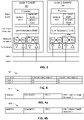
- FIG. 3 illustrates an example of PRP modules operating under IEC standard 62439-3.
- the two PRP modules include a first doubly attached node obeying to PRP (DANP1) 302 labeled in this disclosure as node 1.
- a second doubly attached node obeying to PRP (DANP2) 304 is labeled node 2.
- node 1 will be used as the source node and node 2 as the destination node.
- Each PRP module 302, 304 includes a processor, in the Upper Layers of modules 302 and 304 that can use any processing device including one or more processors or other processing devices that can execute an operating system instructions including a protocol stack.
- the protocol stack can be implemented in hypertext transfer protocol (HTTP) and may include a transmission control protocol (TCP) at a transport layer, and an IP Internet protocol (IP) at the network layer.
- HTTP hypertext transfer protocol
- TCP transmission control protocol
- IP IP Internet protocol
- the PRP modules further include TX/RX circuitry which implement the PRP-related functions described herein, as they pertain to the communication stack of the link redundancy entity (LRE) from IEC standard 62439-3.
- LRE link redundancy entity
- PRP-compatible nodes are connected to two independent network LANs having similar topology, e.g., a network 1 comprised of LAN A and a second network 2 comprised of LAN B. through two independent physical ports (port A and port B).
- the physical ports include circuitry such as transmit (TX) and receive (RX) circuitry and transceivers for dealing with the physical connectivity of the corresponding DANP1 and DANP2 nodes.
- Each pair of ports A and B for the same node share the same MAC address but operate in parallel and are attached to the same upper layers of the protocol stack, e.g., through a link redundancy entity (LRE).
- LRE link redundancy entity
- the LRE ensures that the upper layers are unaware of, and unaffected by, the redundancy.
- the LRE performs two key tasks related to the PRP-related functions described herein, the LRE handles the duplication of PRP frames and manages acceptance of the received packets from network 1 and network 2.
- the upper layers of the protocol stack attaches a MAC header to the data packet and converts it to an IEEE 802.3 frame, as is done in non-redundant networks.
- the MAC header includes a source MAC address field, a destination MAC address field, and other fields such as a tag and an Ethernet type/size field for an Ethernet frame.
- the LRE uses the same destination MAC address for the destination within a network.
- the LRE duplicates the data frame received from the upper layers and appends a redundancy check trailer (RCT) to each duplicated data frame.
- RCT redundancy check trailer
- the RCT includes a sequence number field (SeqNr), a LAN identifier field (LanID), a frame size field (LSDU size) and a PRP suffix which identifies the new (appended) frame as a PRP frame.
- SeqNr sequence number field
- LiD LAN identifier field
- LSDU size frame size field
- PRP suffix which identifies the new (appended) frame as a PRP frame.
- FIG.4 represents a simplified MAC address identifier 400 used in the example PRP network of FIG. 3 .
- the MAC addresses in this example have been simplified for ease of explanation.
- the node 1 PRP module DANP1 includes a network 1 MAC address A1 and a network 2 MAC address A1.
- the node 2 PRP module, DANP2 includes a network 1 MAC address A2 and network 2 MAC address A2.
- the MAC addresses in the illustrated node identifiers node 1 and node 2, shown at FIG. 4 are the same and are identical.
- the sending node LRE duplicates a packet of data for transmission in the LRE.
- the data packet is packaged into a frame that includes the destination MAC address, the source MAC address, the data and the RCT.
- FIG. 4a shows a data frame 402 that will be transmitted on network 1.
- the MAC header identifies that the data packet source was MAC address A1 from node 1, the destination is MAC address A2 at node 2.
- the RCT of the frame includes the seq number and identifies that the data packet was transmitted on network 1.
- Fig. 4b illustrates the data packet frame 404 that is transmitted on network 2.
- This data packet frame includes a duplicated data packet as used in data packet frame 402 of FIG. 4a .
- the source MAC address is A1
- the destination MAC address is A2 and are equivalent to the source and destination addresses in data packet frame 402 even though the packet is transmitted along network 2.
- the LRE transfers the data packet frames to the transmitter of Port A associated with LAN 1 and the transmitter of port B associated with LAN 2
- the two PRP frames travel through LAN 1 and LAN 2 with different delays and, ideally, both reach the destination node 2.
- the LRE of receiving node 2 consumes the first PRP frame and discards the second one (if it arrives).
- the MAC address of the source node, node 1 in this example is used to identify the received PRP frame.
- the sequence number in the RCT is combined with the original Source MAC address and used in identifying data frame.
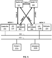
- FIG. 5 illustrates a private network for transporting data between controllers 202 and gateways 204 in accordance with the present disclosure.
- a first network node 1 is formed by controller 202, I/O module 114, and interface module 302.
- a second network node 2 is formed by a gateway 204, I/O module 104b and interface module 304.
- Interface modules 302 and 304 are PRP modules operating under IEC standard 62439-3.
- the two interface modules 302-304 include a first doubly attached node obeying to PRP (DANP1) and a second doubly attached node obeying to PRP (DANP2), as explained above for FIG. 3 .
- the controller 202 is connected to and communicates via one or more networks 108 and associated switches, firewalls, to other components of the industrial process control system.
- the sensors 102a and actuators 102b of this control group are connected to an I/O module 104a and 104b via one or more networks 103 and to an associated gateway 204 as was explained above.
- the PRP network sends data from the controller 202 of node 1 to the gateway 204 of node 2 using two independent LAN networks.
- interface module 302 associated with network node 1 communicates using LAN network 1 (hereinafter network 1) comprised of a first cable A connected between module 302, an ethernet switch A 502 and a second cable A' connected from Ethernet switch A to interface module 304.
- interface module 302 is connected to LAN network 2 (hereinafter network 2) via a first cable B to ethernet switch B 504 and second cable B' connected to interface module 304.
- the interface modules 302-304 through their associated ethernet switches 502-504 establish two separate networks, networks 1 and network 2, between controller 202 and gateway 204.
- the disclosure of the present invention includes a cable C operatively connecting ethernet switch A and switch B. Therefore, the redundant network 1 and network 2 of the present disclosure are interconnected allowing for the crossover of MAC address identifiers between networks 1 and 2.
- PRP has a built-in design to include network information to which a packet belongs to
- managed switching equipment will see the same MAC address from two different ports and report MAC flapping errors. This results in spanning tree recovery procedures incorrectly being administered.
- flapping failures can be prevented.
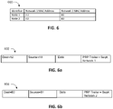
- the MAC addressing scheme of the present disclosure requires each PRP, in this example, PRP 302-304, build a partner MAC address table 600 that lists each of the two MAC addresses of the nodes connected to the network as shown in FIG. 6 .
- the network topology may include more than two nodes, however, only two nodes will be used in this example for ease of explanation.
- Cable C interconnecting switch A and switch B allows each interface module 302-304 to discover and share the MAC addresses used by nodes 1 and nodes 2. Therefore, each node shares its MAC addresses with the other nodes connected in the network.
- Each MAC address and its partner MAC address is identified in accordance with the network it is associated with. For example, from the table 600 of FIG.
- Each interface module 302-304 includes the partner MAC address table 600 which is used to assign the proper MAC address for data packet transmission along networks 1 and 2.
- the MAC addresses contained in the MAC address table 600 is used by the PRP 302-304 to build the MAC header.
- the protocol stack of the sending node PRP would look up the destination MAC addresses of the destination from the MAC address table and send the original data packet from source A1 to destination A2 using network 1 in accordance to frame 602.
- the duplicate packet would be sent to node 2 MAC address B2 from node 1 MAC address B1 along network 2 as shown in frame 604. Therefore, in the MAC addressing scheme of the present disclosure, MAC address A1 is not equal to and is not the same as MAC address B1. Similarly, MAC address A2 is not equal to and is not the same as MAC address B2.
- PRP for example PRP 304, consumes the first PRP frame that arrives and discards the second one (if it arrives).
- the MAC address of the source node 302 in this example is used to identify the received PRP frame.
- the sequence number in the RCT is combined with the original source MAC address and used in identifying the data frame. Because the MAC addresses in this example are not shared or duplicated, for example source MAC addresses A1 and source MAC address is B1, any interconnection of cables A and B or A' and B' between networks 1 and 2 if inadvertently made, does not trigger network errors.
- FIG . 7 illustrates a diagram of an example method 700 for building the PRP data packet frames 602 and 604 as shown in FIG 6a and FIG 6b respectively, according to this disclosure.
- the method 700 is described with respect to the system 100 of FIG.1 , although the method 700 could implemented in any other suitable system. Also, the method 700 is implemented using the controller nodes 1 and 2 of FIG. 5 , although the method 700 can be implemented in any other suitable manner.
- the assembly of data packet frames starts at step 701 with the source interface module looking up the source and destination MAC addresses received from the protocol stack.
- a decision step 702 is made in which the method looks to see if the source MAC address received is in network 1. If the source MAC address is in network 2 then the method branches off at step 704. If the source MAC address is in network , then a second decision step is made at 706 to ascertain if the destination MAC address is in network 1. If the destination is in network 1 then the method of the disclosure replaces the original MAC addresses in the following manner.
- a duplicate data packet frame is created and named AltSendCopy.
- the source MAC address of the duplicate data frame is replaced with the partner source MAC address.
- the original data packet frame is transmitted on network 1 and the AltSendCopy data packet on network 2.
- the original data packet frame is transmitted along network 1 from MAC address A1 using a destination MAC address A2.
- the AltSendCopy data packet is transmitted along network 2 having source MAC address B1 using a destination MAC address B2. Since the are no duplications of the source and destination MAC addresses, if a cross connection is inadvertently made the receiving node does not see duplicated MAC addresses.
- step 709 a duplicate data packet frame is created and named AltSendCopy.
- the program replaces the destination MAC address of the original data packet frame of B1 to A2.
- step 713 the destination MAC address of the original data packet frame of B2, is replaced by the MAC address A2.
- the original data packet frame is transmitted along network 1 using a destination MAC address A2.
- the AltSendCopy data packet frame is transmitted along network 2 using a destination MAC address B2.
- Fig. 8 illustrates the method of the present invention wherein the method branches off at 704, due to the source MAC address originating in network 2.
- the method looks to see if the destination MAC address is in network 1. If it is, A duplicate data packet frame is created named AltSendCopy in step 734.
- step 736 the source MAC address B2 is replaced with partner source MAC address A2 in the AltSendCopy.
- the destination MAC address in original data packet frame is replaced with the partner MAC address replacing it from A1 to B1.
- the AltSendCopy data packet frame is transmitted from source MAC address A2 in node 2 to destination MAC address A1 in node 1 over network 1.
- the original data packet frame is transmitted over network 2 using MAC address B2 to destination MAC address B1.
- step 732 if the destination MAC address is in network 2 the conditional branch 731 is taken.
- step 733 again a duplicate data packet frame is created named AltSendCopy.
- step 735 the source MAC address of the AltSendCopy frame is replaced with partner source MAC address, A1.
- step 737 the destination MAC address of the AltSendCopy is replaced with the partner MAC address A2.
- step 740 the original data packet frame is transmitted from source MAC address B1 to destination MAC address B2 over network 2.
- step 745 at the same instance, the AltSendCopy data packet frame is transmitted over network 1 using MAC address A1 to destination MAC address A2.
- the PRP consumes the first data packet frame that arrives and discards the second one (if it arrives). In the manner as earlier described for a normal PRP node.
- the network 1 MAC address has priority and is selected to replace all other incoming data packet frames. If a network 2 source MAC address arrives first, the network 1 the source MAC address is looked-up in the MAC address table and all the incoming packet source MAC addresses are replaced with the network 1 source partner MAC address.
- various functions described in this patent document are implemented or supported by a computer program that is formed from computer readable program code and that is embodied in a computer readable medium.
- computer readable program code includes any type of computer code, including source code, object code, and executable code.
- computer readable medium includes any type of medium capable of being accessed by a computer, such as read only memory (ROM), random access memory (RAM), a hard disk drive, a compact disc (CD), a digital video disc (DVD), or any other type of memory.
- ROM read only memory
- RAM random access memory
- CD compact disc
- DVD digital video disc
- a “non-transitory” computer readable medium excludes wired, wireless, optical, or other communication links that transport transitory electrical or other signals.
- a non-transitory computer readable medium includes media where data can be permanently stored and media where data can be stored and later overwritten, such as a rewritable optical disc or an erasable memory device.
- application and “program” refer to one or more computer programs, software components, sets of instructions, procedures, functions, objects, classes, instances, related data, or a portion thereof adapted for implementation in a suitable computer code (including source code, object code, or executable code).
- program refers to one or more computer programs, software components, sets of instructions, procedures, functions, objects, classes, instances, related data, or a portion thereof adapted for implementation in a suitable computer code (including source code, object code, or executable code).
- communicate as well as derivatives thereof, encompasses both direct and indirect communication.
- the term “or” is inclusive, meaning and/or.
- phrases "associated with,” as well as derivatives thereof, may mean to include, be included within, interconnect with, contain, be contained within, connect to or with, couple to or with, be communicable with, cooperate with, interleave, juxtapose, be proximate to, be bound to or with, have, have a property of, have a relationship to or with, or the like.
- the phrase "at least one of,” when used with a list of items, means that different combinations of one or more of the listed items may be used, and only one item in the list may be needed. For example, "at least one of: A, B, and C" includes any of the following combinations: A, B, C, A and B, A and C, B and C, and A and B and C.
Landscapes
- Engineering & Computer Science (AREA)
- Computer Networks & Wireless Communication (AREA)
- Signal Processing (AREA)
- Computer Security & Cryptography (AREA)
- Data Exchanges In Wide-Area Networks (AREA)
- Small-Scale Networks (AREA)
- Communication Control (AREA)
Applications Claiming Priority (1)
| Application Number | Priority Date | Filing Date | Title |
|---|---|---|---|
| US17/222,178 US11303568B1 (en) | 2021-04-05 | 2021-04-05 | Method and system for parallel redundancy protocol in connected networks |
Publications (2)
| Publication Number | Publication Date |
|---|---|
| EP4072104A1 true EP4072104A1 (de) | 2022-10-12 |
| EP4072104B1 EP4072104B1 (de) | 2025-05-28 |
Family
ID=80819904
Family Applications (1)
| Application Number | Title | Priority Date | Filing Date |
|---|---|---|---|
| EP22162879.5A Active EP4072104B1 (de) | 2021-04-05 | 2022-03-18 | Verfahren und system für ein paralleles redundanzprotokoll in verbundenen netzen |
Country Status (4)
| Country | Link |
|---|---|
| US (1) | US11303568B1 (de) |
| EP (1) | EP4072104B1 (de) |
| CN (1) | CN115208967B (de) |
| AU (1) | AU2022201517B2 (de) |
Cited By (2)
| Publication number | Priority date | Publication date | Assignee | Title |
|---|---|---|---|---|
| EP4492757A1 (de) * | 2023-07-11 | 2025-01-15 | Yokogawa Electric Corporation | Informationsverarbeitungsprogramm, informationsverarbeitungsverfahren und informationsverarbeitungsvorrichtung |
| EP4554178A1 (de) * | 2023-11-13 | 2025-05-14 | Honeywell International Inc. | Verfahren und system für ein vierweg-parallelredundanzprotokoll in verbundenen netzwerken |
Families Citing this family (3)
| Publication number | Priority date | Publication date | Assignee | Title |
|---|---|---|---|---|
| US11436109B1 (en) * | 2021-08-31 | 2022-09-06 | Schweitzer Engineering Laboratories, Inc. | Systems and methods for communicating data securely for an electric power delivery system |
| US12166673B2 (en) * | 2022-04-08 | 2024-12-10 | Arista Networks, Inc. | Media access control address rewrite using egress header editing in traffic aggregation mode |
| US20250379812A1 (en) * | 2024-06-07 | 2025-12-11 | Siemens Canada Limited | Layer 3 router and method for routing prp frames |
Citations (2)
| Publication number | Priority date | Publication date | Assignee | Title |
|---|---|---|---|---|
| WO2016097459A1 (en) * | 2014-12-16 | 2016-06-23 | Metso Automation Oy | Redundancy in process control system |
| US20170195260A1 (en) * | 2015-12-31 | 2017-07-06 | Abb Schweiz Ag | Parallel redundancy protocol over wide area networks |
Family Cites Families (6)
| Publication number | Priority date | Publication date | Assignee | Title |
|---|---|---|---|---|
| EP3369222B1 (de) * | 2015-10-26 | 2019-01-02 | ABB Schweiz AG | Verfahren, knoten und system zur herstellung von unabhängigen netzwerkpfaden |
| US10333652B2 (en) * | 2016-09-16 | 2019-06-25 | International Business Machines Corporation | Redundancy in converged networks |
| EP3343303B1 (de) * | 2016-12-29 | 2019-06-26 | Siemens Aktiengesellschaft | Funk-kommunikationssystem für ein industrielles automatisierungssystem, verfahren zu dessen betrieb |
| US10194308B2 (en) * | 2017-03-29 | 2019-01-29 | Cisco Technology, Inc. | Wireless network roaming in high-speed movement applications |
| CN109005088B (zh) | 2018-09-28 | 2020-07-17 | 北京东土科技股份有限公司 | 并行冗余网络中重复报文的检测方法和装置 |
| CN111447186B (zh) | 2020-03-17 | 2022-04-26 | 重庆邮电大学 | 一种时间敏感网络帧复制与消除和无缝冗余互联方法 |
-
2021
- 2021-04-05 US US17/222,178 patent/US11303568B1/en active Active
-
2022
- 2022-03-04 AU AU2022201517A patent/AU2022201517B2/en active Active
- 2022-03-18 EP EP22162879.5A patent/EP4072104B1/de active Active
- 2022-03-28 CN CN202210309432.5A patent/CN115208967B/zh active Active
Patent Citations (2)
| Publication number | Priority date | Publication date | Assignee | Title |
|---|---|---|---|---|
| WO2016097459A1 (en) * | 2014-12-16 | 2016-06-23 | Metso Automation Oy | Redundancy in process control system |
| US20170195260A1 (en) * | 2015-12-31 | 2017-07-06 | Abb Schweiz Ag | Parallel redundancy protocol over wide area networks |
Cited By (3)
| Publication number | Priority date | Publication date | Assignee | Title |
|---|---|---|---|---|
| EP4492757A1 (de) * | 2023-07-11 | 2025-01-15 | Yokogawa Electric Corporation | Informationsverarbeitungsprogramm, informationsverarbeitungsverfahren und informationsverarbeitungsvorrichtung |
| JP2025011627A (ja) * | 2023-07-11 | 2025-01-24 | 横河電機株式会社 | 情報処理プログラム、情報処理方法、および情報処理装置 |
| EP4554178A1 (de) * | 2023-11-13 | 2025-05-14 | Honeywell International Inc. | Verfahren und system für ein vierweg-parallelredundanzprotokoll in verbundenen netzwerken |
Also Published As
| Publication number | Publication date |
|---|---|
| EP4072104B1 (de) | 2025-05-28 |
| AU2022201517A1 (en) | 2022-10-20 |
| CN115208967A (zh) | 2022-10-18 |
| CN115208967B (zh) | 2025-11-04 |
| AU2022201517B2 (en) | 2023-07-13 |
| US11303568B1 (en) | 2022-04-12 |
Similar Documents
| Publication | Publication Date | Title |
|---|---|---|
| EP4072104B1 (de) | Verfahren und system für ein paralleles redundanzprotokoll in verbundenen netzen | |
| US8055814B2 (en) | Universal safety I/O module | |
| US9699022B2 (en) | System and method for controller redundancy and controller network redundancy with ethernet/IP I/O | |
| CN101753348B (zh) | 一种高可用性工业以太网冗余方法 | |
| CN103581164B (zh) | 用于在可冗余操作的工业通信网络中进行消息传输的方法和用于可冗余操作的工业通信网络的通信设备 | |
| FI128272B (en) | Redundancy in the process control system | |
| US8249084B2 (en) | Ring connection control circuit, ring switching hub, ring ethernet system, and ring connection controlling method | |
| EP4554178A1 (de) | Verfahren und system für ein vierweg-parallelredundanzprotokoll in verbundenen netzwerken | |
| EP4149063B1 (de) | Verfahren und vorrichtung für einen alternativen kommunikationspfad für verbundene netzwerke | |
| AU2023200276B2 (en) | Modular control network architecture | |
| US20240007233A1 (en) | Edge Device and Method for Providing Redundancy Functions on the Edge Device | |
| US12526205B2 (en) | Decentralized network discovery for industrial control systems | |
| EP4607860A1 (de) | Verfahren zur übertragung von steuerrahmen gemäss einem redundanzprotokoll und netzwerkvorrichtung | |
| EP4742617A1 (de) | Verfahren zur übertragung von datagrammen gemäss einem redundanzprotokoll und netzwerkgerät | |
| US20240205072A1 (en) | Apparatus and method for locating faults in ethernet ring networks | |
| EP4718787A1 (de) | Virtuelles netzgateway | |
| WO2026099031A1 (en) | Method of transmitting datagrams according to a redundancy protocol and network device |
Legal Events
| Date | Code | Title | Description |
|---|---|---|---|
| PUAI | Public reference made under article 153(3) epc to a published international application that has entered the european phase |
Free format text: ORIGINAL CODE: 0009012 |
|
| STAA | Information on the status of an ep patent application or granted ep patent |
Free format text: STATUS: REQUEST FOR EXAMINATION WAS MADE |
|
| 17P | Request for examination filed |
Effective date: 20220318 |
|
| AK | Designated contracting states |
Kind code of ref document: A1 Designated state(s): AL AT BE BG CH CY CZ DE DK EE ES FI FR GB GR HR HU IE IS IT LI LT LU LV MC MK MT NL NO PL PT RO RS SE SI SK SM TR |
|
| P01 | Opt-out of the competence of the unified patent court (upc) registered |
Effective date: 20230414 |
|
| GRAP | Despatch of communication of intention to grant a patent |
Free format text: ORIGINAL CODE: EPIDOSNIGR1 |
|
| STAA | Information on the status of an ep patent application or granted ep patent |
Free format text: STATUS: GRANT OF PATENT IS INTENDED |
|
| INTG | Intention to grant announced |
Effective date: 20250123 |
|
| GRAS | Grant fee paid |
Free format text: ORIGINAL CODE: EPIDOSNIGR3 |
|
| GRAA | (expected) grant |
Free format text: ORIGINAL CODE: 0009210 |
|
| STAA | Information on the status of an ep patent application or granted ep patent |
Free format text: STATUS: THE PATENT HAS BEEN GRANTED |
|
| AK | Designated contracting states |
Kind code of ref document: B1 Designated state(s): AL AT BE BG CH CY CZ DE DK EE ES FI FR GB GR HR HU IE IS IT LI LT LU LV MC MK MT NL NO PL PT RO RS SE SI SK SM TR |
|
| REG | Reference to a national code |
Ref country code: GB Ref legal event code: FG4D |
|
| REG | Reference to a national code |
Ref country code: CH Ref legal event code: EP |
|
| REG | Reference to a national code |
Ref country code: IE Ref legal event code: FG4D Ref country code: DE Ref legal event code: R096 Ref document number: 602022015108 Country of ref document: DE |
|
| PG25 | Lapsed in a contracting state [announced via postgrant information from national office to epo] |
Ref country code: ES Free format text: LAPSE BECAUSE OF FAILURE TO SUBMIT A TRANSLATION OF THE DESCRIPTION OR TO PAY THE FEE WITHIN THE PRESCRIBED TIME-LIMIT Effective date: 20250528 Ref country code: FI Free format text: LAPSE BECAUSE OF FAILURE TO SUBMIT A TRANSLATION OF THE DESCRIPTION OR TO PAY THE FEE WITHIN THE PRESCRIBED TIME-LIMIT Effective date: 20250528 |
|
| REG | Reference to a national code |
Ref country code: LT Ref legal event code: MG9D |
|
| PG25 | Lapsed in a contracting state [announced via postgrant information from national office to epo] |
Ref country code: NO Free format text: LAPSE BECAUSE OF FAILURE TO SUBMIT A TRANSLATION OF THE DESCRIPTION OR TO PAY THE FEE WITHIN THE PRESCRIBED TIME-LIMIT Effective date: 20250828 Ref country code: GR Free format text: LAPSE BECAUSE OF FAILURE TO SUBMIT A TRANSLATION OF THE DESCRIPTION OR TO PAY THE FEE WITHIN THE PRESCRIBED TIME-LIMIT Effective date: 20250829 |
|
| PG25 | Lapsed in a contracting state [announced via postgrant information from national office to epo] |
Ref country code: NL Free format text: LAPSE BECAUSE OF FAILURE TO SUBMIT A TRANSLATION OF THE DESCRIPTION OR TO PAY THE FEE WITHIN THE PRESCRIBED TIME-LIMIT Effective date: 20250528 Ref country code: PL Free format text: LAPSE BECAUSE OF FAILURE TO SUBMIT A TRANSLATION OF THE DESCRIPTION OR TO PAY THE FEE WITHIN THE PRESCRIBED TIME-LIMIT Effective date: 20250528 |
|
| PG25 | Lapsed in a contracting state [announced via postgrant information from national office to epo] |
Ref country code: BG Free format text: LAPSE BECAUSE OF FAILURE TO SUBMIT A TRANSLATION OF THE DESCRIPTION OR TO PAY THE FEE WITHIN THE PRESCRIBED TIME-LIMIT Effective date: 20250528 |
|
| PG25 | Lapsed in a contracting state [announced via postgrant information from national office to epo] |
Ref country code: HR Free format text: LAPSE BECAUSE OF FAILURE TO SUBMIT A TRANSLATION OF THE DESCRIPTION OR TO PAY THE FEE WITHIN THE PRESCRIBED TIME-LIMIT Effective date: 20250528 |
|
| PG25 | Lapsed in a contracting state [announced via postgrant information from national office to epo] |
Ref country code: RS Free format text: LAPSE BECAUSE OF FAILURE TO SUBMIT A TRANSLATION OF THE DESCRIPTION OR TO PAY THE FEE WITHIN THE PRESCRIBED TIME-LIMIT Effective date: 20250828 |
|
| PG25 | Lapsed in a contracting state [announced via postgrant information from national office to epo] |
Ref country code: IS Free format text: LAPSE BECAUSE OF FAILURE TO SUBMIT A TRANSLATION OF THE DESCRIPTION OR TO PAY THE FEE WITHIN THE PRESCRIBED TIME-LIMIT Effective date: 20250928 |
|
| PG25 | Lapsed in a contracting state [announced via postgrant information from national office to epo] |
Ref country code: LV Free format text: LAPSE BECAUSE OF FAILURE TO SUBMIT A TRANSLATION OF THE DESCRIPTION OR TO PAY THE FEE WITHIN THE PRESCRIBED TIME-LIMIT Effective date: 20250528 |
|
| REG | Reference to a national code |
Ref country code: AT Ref legal event code: MK05 Ref document number: 1799305 Country of ref document: AT Kind code of ref document: T Effective date: 20250528 |
|
| PG25 | Lapsed in a contracting state [announced via postgrant information from national office to epo] |
Ref country code: SM Free format text: LAPSE BECAUSE OF FAILURE TO SUBMIT A TRANSLATION OF THE DESCRIPTION OR TO PAY THE FEE WITHIN THE PRESCRIBED TIME-LIMIT Effective date: 20250528 Ref country code: AT Free format text: LAPSE BECAUSE OF FAILURE TO SUBMIT A TRANSLATION OF THE DESCRIPTION OR TO PAY THE FEE WITHIN THE PRESCRIBED TIME-LIMIT Effective date: 20250528 Ref country code: DK Free format text: LAPSE BECAUSE OF FAILURE TO SUBMIT A TRANSLATION OF THE DESCRIPTION OR TO PAY THE FEE WITHIN THE PRESCRIBED TIME-LIMIT Effective date: 20250528 |
|
| PG25 | Lapsed in a contracting state [announced via postgrant information from national office to epo] |
Ref country code: CZ Free format text: LAPSE BECAUSE OF FAILURE TO SUBMIT A TRANSLATION OF THE DESCRIPTION OR TO PAY THE FEE WITHIN THE PRESCRIBED TIME-LIMIT Effective date: 20250528 |
|
| PG25 | Lapsed in a contracting state [announced via postgrant information from national office to epo] |
Ref country code: EE Free format text: LAPSE BECAUSE OF FAILURE TO SUBMIT A TRANSLATION OF THE DESCRIPTION OR TO PAY THE FEE WITHIN THE PRESCRIBED TIME-LIMIT Effective date: 20250528 |
|
| PG25 | Lapsed in a contracting state [announced via postgrant information from national office to epo] |
Ref country code: SK Free format text: LAPSE BECAUSE OF FAILURE TO SUBMIT A TRANSLATION OF THE DESCRIPTION OR TO PAY THE FEE WITHIN THE PRESCRIBED TIME-LIMIT Effective date: 20250528 |
|
| PG25 | Lapsed in a contracting state [announced via postgrant information from national office to epo] |
Ref country code: IT Free format text: LAPSE BECAUSE OF FAILURE TO SUBMIT A TRANSLATION OF THE DESCRIPTION OR TO PAY THE FEE WITHIN THE PRESCRIBED TIME-LIMIT Effective date: 20250528 |
|
| REG | Reference to a national code |
Ref country code: DE Ref legal event code: R097 Ref document number: 602022015108 Country of ref document: DE |
|
| PLBE | No opposition filed within time limit |
Free format text: ORIGINAL CODE: 0009261 |
|
| STAA | Information on the status of an ep patent application or granted ep patent |
Free format text: STATUS: NO OPPOSITION FILED WITHIN TIME LIMIT |
|
| PGFP | Annual fee paid to national office [announced via postgrant information from national office to epo] |
Ref country code: GB Payment date: 20260319 Year of fee payment: 5 |
|
| REG | Reference to a national code |
Ref country code: CH Ref legal event code: L10 Free format text: ST27 STATUS EVENT CODE: U-0-0-L10-L00 (AS PROVIDED BY THE NATIONAL OFFICE) Effective date: 20260409 |
|
| PGFP | Annual fee paid to national office [announced via postgrant information from national office to epo] |
Ref country code: DE Payment date: 20260320 Year of fee payment: 5 |
|
| 26N | No opposition filed |
Effective date: 20260303 |