EP4071950B1 - Improved mounting system for busbars of an electrical switchgear - Google Patents
Improved mounting system for busbars of an electrical switchgear Download PDFInfo
- Publication number
- EP4071950B1 EP4071950B1 EP22162748.2A EP22162748A EP4071950B1 EP 4071950 B1 EP4071950 B1 EP 4071950B1 EP 22162748 A EP22162748 A EP 22162748A EP 4071950 B1 EP4071950 B1 EP 4071950B1
- Authority
- EP
- European Patent Office
- Prior art keywords
- holder
- busbar
- mounting system
- busbars
- rails
- Prior art date
- Legal status (The legal status is an assumption and is not a legal conclusion. Google has not performed a legal analysis and makes no representation as to the accuracy of the status listed.)
- Active
Links
Images


Classifications
-
- H—ELECTRICITY
- H02—GENERATION; CONVERSION OR DISTRIBUTION OF ELECTRIC POWER
- H02B—BOARDS, SUBSTATIONS OR SWITCHING ARRANGEMENTS FOR THE SUPPLY OR DISTRIBUTION OF ELECTRIC POWER
- H02B1/00—Frameworks, boards, panels, desks, casings; Details of substations or switching arrangements
- H02B1/20—Bus-bar or other wiring layouts, e.g. in cubicles, in switchyards
-
- H—ELECTRICITY
- H01—ELECTRIC ELEMENTS
- H01B—CABLES; CONDUCTORS; INSULATORS; SELECTION OF MATERIALS FOR THEIR CONDUCTIVE, INSULATING OR DIELECTRIC PROPERTIES
- H01B17/00—Insulators or insulating bodies characterised by their form
- H01B17/56—Insulating bodies
-
- H—ELECTRICITY
- H02—GENERATION; CONVERSION OR DISTRIBUTION OF ELECTRIC POWER
- H02G—INSTALLATION OF ELECTRIC CABLES OR LINES, OR OF COMBINED OPTICAL AND ELECTRIC CABLES OR LINES
- H02G5/00—Installations of bus-bars
-
- H—ELECTRICITY
- H02—GENERATION; CONVERSION OR DISTRIBUTION OF ELECTRIC POWER
- H02G—INSTALLATION OF ELECTRIC CABLES OR LINES, OR OF COMBINED OPTICAL AND ELECTRIC CABLES OR LINES
- H02G5/00—Installations of bus-bars
- H02G5/02—Open installations
- H02G5/025—Supporting structures
-
- H—ELECTRICITY
- H02—GENERATION; CONVERSION OR DISTRIBUTION OF ELECTRIC POWER
- H02B—BOARDS, SUBSTATIONS OR SWITCHING ARRANGEMENTS FOR THE SUPPLY OR DISTRIBUTION OF ELECTRIC POWER
- H02B1/00—Frameworks, boards, panels, desks, casings; Details of substations or switching arrangements
- H02B1/20—Bus-bar or other wiring layouts, e.g. in cubicles, in switchyards
- H02B1/21—Bus-bar arrangements for rack-mounted devices with withdrawable units
Definitions
- the invention relates to a mounting system for busbars of an electrical switchgear, which comprises a plurality of holder rails, connection profiles to interconnect the holder rails and to effect a distance between the holder rails and which comprises a plurality of busbar holders, which are provided to receive the busbars and which are arranged in the holder rails. Moreover, the invention relates to an arrangement with a plurality of busbars and a mounting system of the above kind, by which the busbars are fixed. Finally, the invention relates to an electrical switchgear, which comprises a number of busbars, at least one switching device electrically connected to the busbars and a mounting system of the above kind, by which the busbars are held in position within the electrical switchgear.
- the holder rails are made of metal and the busbar holders are made of plastic so as to provide electrical insulation between the bus bar holders and thus between the busbars held by the busbar holders.
- the busbar holders are relatively soft and often cannot absorb the forces, which are induced by the busbars, in particularly in case of short circuit, in which the busbars are heavily pressed against the busbar holders.
- a busbar retention device for power busbars which has a first and a second rail holder designed for common clamp-type gripping around the power busbars.
- the first and second holder rails are formed from plastic, and comprise busbar holders made from a metallic material, specifically non-magnetic, e.g. of special steel.
- Socomec (“CATALOGUE EXTRACT 2016 Busbar supports", URL: https://techmech.yolasite.com/resources/SOCOMEC%20Busbar%20supports.pdf XP055950781) discloses insulating busbar supports comprising plastic holder rails and metallic (copper) busbar holders, see pages 4-5.
- DE 70 31 014 U discloses a separator for selectively separating and bridging the rail ends of busbars, consisting of a movable bridge that can be clamped to the rail ends and a lower part for supporting the rail ends.
- This clamping support also comprises holder rails made of plastic and busbar holders made of metal.
- an object of the invention is the provision of an improved mounting system, an improved arrangement with such a mounting system and an improved switchgear.
- a solution shall be proposed, which inter alia better absorbs forces induced by the busbars and which avoids induced currents or eddy currents in the mounting system.
- the object of the invention is solved by an arrangement with a plurality of busbars and a mounting system of the above kind, by which the busbars are fixed.
- an electrical switchgear which comprises a number of busbars, at least one switching device electrically connected to the busbars and a mounting system of the above kind, by which the busbars are held in position within the electrical switchgear.
- busbar holders are comparably robust and easily withstand the (electromagnetic) forces occurring in a switchgear. Because the contact surface between a busbar holder and a holder rail is comparably large, in addition those high forces can easily be transferred from the busbar holder to the holder rail, despite the fact that the holder rail is made from plastic. Moreover, the holder rail provides electrical insulation and hence also avoids induced eddy currents caused by the current through the busbars. A closed ferrous material loop around the busbars is avoided naturally by the non-ferrous material of the proposed holder rail. This is not the case for prior art holder rails made of metal where special measures have to be taken to avoid such a ferrous material loop and to avoid or at least limit said induced currents or eddy currents.
- the holder rails can be made from fiber reinforced resin and particularly by use of pultrusion.
- Pultrusion provides the advantage that areas of different fiber density can be defined within the holder rails.
- the holder rails can be made more robust where it is desired.
- Pultrusion provides the further advantage that holder rails can be produced in standard lengths (several meters) and can be cut later on as desired to fit in any application. Accordingly, the mounting system can be adapted to different numbers of busbars easily.
- connection profiles can be produced in standard lengths (several meters) by use of pultrusion and can be cut as desired to fit in any application as well. Accordingly, the mounting system can be adapted to different heights of the busbars easily.
- the connection profiles can be made of plastic or of metal.
- one further advantage of the proposed solution is that a big range of busbar dimensions and/or busbar configurations can be covered by the mounting system although the parts which are used therefore basically remain the same for all these busbar dimensions and/or busbar configurations. So, flexibility of the mounting system is increased at reduced costs compared to prior art systems.
- the holder rails are strut profiles with an H cross section.
- busbar holders can be received in one opening of the "H” and means for mounting the busbar holders, e.g. busbar holder screws or rivets, can be received in the opposite opening of the "H".
- the heads of the mounting means e.g. the heads of the busbar holder screws or rivets, are located in a groove so as to provide protection against unintentional contact by personnel.
- mounting means can be under voltage if they are made from metal, if no other measures are be taken to avoid that.
- a H cross section beneficially provides good stiffness against deflection.
- the holder rails can have a U cross section or a square pipe cross section.
- the H cross section of the holder rails comprises grooves on both sides of the bottom region facing the busbar holders.
- protrusions on the busbar holders or on other equipment which can be fixed to the holder rails, can reach into the grooves.
- a busbar holder or other equipment can be snapped in a holder rail so that it does not fall out of the holder rail unintentionally until the busbar holder or other equipment is finally fixed to the holder rail by mounting means, e.g. by busbar holder screws or rivets. This is particularly helpful if a busbar holder or other equipment shall be mounted to a holder rail upside down.
- the busbar holders are strut profiles with a square pipe cross section and with cutouts for the busbars. Accordingly, the busbar holders can easily cut off from standard profiles and can be manufactured at low cost.
- the cutouts form recesses for receiving the busbars. Beneficially, the cutouts are made by a laser, but however other production techniques are applicable as well.
- a further advantage of the square pipe cross section is that it leads to comparably robust busbar holders.
- different busbar arrangements with different numbers of busbars per busbar holder can be realized easily. The only thing that varies in that respect is the number of cutouts per busbar holder and/or the length of the busbar holder. So, a busbar holder can have one cutout for one busbar, two cutouts for two busbars and so on.
- the busbar holders can be coated/painted in order to reduce friction between the busbar holders and the busbars, to provide electrical isolation and/or to mark each electrical phase with a separate color.
- one busbar can have blue color
- one busbar can have brown color and so on.
- the base material of the busbar holder can have a rough surface.
- Such a rough surface can be made by sandblasting for example, but also by means of a laser, which burns small pits into the surface of the base material of the busbar holder.
- the same laser can be used therefor, which is also used for cutting the cutout. It is also possible, that only surfaces of the busbar holder are provided with these pits which potentially get into contact with other parts.
- the edges of the cutouts can be provided with pits to locally improve adhesion there.
- a top region of the cutout has convex or curved sections on both sides.
- These convex or curved sections provide a number of advantages. First, inserting a busbar into a cutout is eased because the risk for wedging is reduced, even if only a small gap is provided between the busbar and the busbar holder. Second, the surface of a busbar is not scratched when the busbar moves in longitudinal direction, in particular during assembly of the mounting system. This is particularly useful if the busbars are coated, because the coating is not scratched either.
- the convex or curved sections can also have additionally chamfers or radii in order to further improve the above effects.
- the busbars can be bent without causing excessive pressure on the vertical edges of the cutouts. Such a bending for example can occur when high electromagnetic forces act on the busbars.
- Even excessive pressure on the convex or curved sections does not lead to a collapse of the busbar holder because the material choice does avoid that.
- metals and in particular steel have a large range of plastic deformation beyond elastic deformation.
- the material of the busbar holder can plastify locally, but it does not collapse as whole. For example, such pressure can occur in case of excessive currents in the busbar and the resulting electromagnetic forces resulting thereof during a short circuit.
- a bottom region of the cutout has a flat or convex elevation with rounded corners on both sides of the elevation.
- Such excessive forces can cause a deformation in a way that a longitudinal axis of the busbar holder becomes arc shaped. For example, this may happen if more than one busbar with the same voltage level is arranged in a busbar holder.
- the busbars of a busbar holder are exposed to different forces what leads to an asymmetric load on the busbar holder. Accordingly, a torque is induced in the busbar holder. If this torque is very high, there is a risk that the fixing of the busbar holder in the holder rail fails (or is missing because e.g. a busbar holder screw or rivet fall of the mounting system during operation) what in turn causes said bending of the busbar holder.
- the elevation or ridge moves towards the busbar.
- the elevation touches the busbar, a further deformation of the busbar holder is avoided or at least hindered. So, the elevation does also act as a hard stop for the busbar holder itself.
- the rounded corners avoid the formation of cracks in the corners of the cutout, not only but particularly in this scenario. So, the mounting system is fault tolerant very much and even a failing or missing fixing of the busbar holder does not lead to a collapse of the whole mounting system.
- busbar holders are fixed to the holder rails by mounting means, which are embodied as self-cutting busbar holder screws.
- mounting means which are embodied as self-cutting busbar holder screws.
- the use of self-cutting busbar holder screws provides a number of advantages. First, no separate thread has to be cut into the busbar holders because a self-cutting busbar holder screw cuts the thread itself. Second, a self-cutting busbar holder screw does not turn out on its own easily, even if the mounting system is exposed to vibrations like they occur within a switchgear. Hence, an additional screw locking can be omitted. Third, self-cutting busbar holder screws can be made shorter than screws, which are fixed by a nut.
- a self-cutting busbar holder screw of the self-cutting busbar holder screws has a threaded portion and an unthreaded portion, wherein the outer diameter of the threaded portion is smaller than the diameter of the unthreaded portion and wherein the threaded portion is screwed into a busbar holder of the busbar holders and the unthreaded portion is located within a holder rail of the holder rails.
- the threaded portion is screwed into a busbar holder hole of a busbar holder and the unthreaded portion is located in a holder rail hole of a holder rail.
- a busbar holder screw as defined hereinbefore can also be seen as a kind of a shoulder screw.
- the busbar holders are fixed to the holder rails by mounting means, which are embodied as rivets, in particular as snap in rivets.
- mounting means which are embodied as rivets, in particular as snap in rivets.
- the assembly of the mounting means always can happen from above, even if the busbar holder is oriented in the upright position.
- the rivet is inserted through the cutout in the busbar holder, and the head of the rivet is located within the busbar holder in the mounted state. If the busbar holder is oriented upside down, then the rivet is inserted through a mounting hole in the holder rail. In neither case, the rivet can fall off by accident easily.
- mounting means for a busbar holder of the busbar holders are located at different distances from and/or at different sides of a longitudinal axis of the holder rail, which said busbar holder is fixed to. In this way, the risk for crack formation in the holder rail can be reduced.
- a width of the busbar holders is slightly below the inside dimension of the H cross section of the holder rail. Accordingly, a busbar holder can be mounted to a holder rail easily. However, it could also be useful if the width of the busbar holder is slightly above the inside dimension of the H cross section of the holder rail. A busbar holder is held in a holder rail by friction then. So, the busbar holder does not fall out of the holder rail unintentionally until the busbar holder is finally fixed to the holder rail by mounting means, e.g. by busbar holder screws or rivets. This is particularly helpful if a busbar holder or other equipment shall be mounted to a holder rail upside down.
- the width of the busbar holders matches the inside dimension of the H cross section, a rotation of the busbar holder is avoided, even if just a single busbar holder screw is used to fix the busbar holder or even if mounting means for the busbar holder, e.g. by busbar holder screws or rivets, unintentionally fall of the mounting system during operation. So, the mounting system is fault tolerant very much, and the holder rail acts as a kind of an assembly jig during assembly what eases manufacturing the mounting system.
- Figs. 1 and 2 show a mounting system 1 for busbars L1..L3, L1', N of an electrical switchgear in perspective view.
- Fig. 1 shows the mounting system 1 in mounted view and Fig. 2 in exploded view.
- the mounting system 1 comprises two holder rails 2a, 2b, connection profiles 3a, 3b to interconnect the holder rails 2a, 2b and to effect a distance between the holder rails 2a, 2b and comprises a plurality of busbar holders 4a, 4b, which are provided to receive the busbars L1..L3, L1', N and which are arranged in the holder rails 2a, 2b.
- the holder rails 2a, 2b are made of plastic and the busbar holders 4a, 4b are made of metal. In this example there is a lower holder rail 2a and an upper holder rail 2b as well as a left connection profile 3a and right connection profile 3b.
- the mounting system 1 comprises frame connectors 5a, 5b, by which the holder rail 2a and thus the whole mounting system 1 can be fixed to the frame of a switchgear. Together with the busbars L1..L3, L1', N the mounting system 1 forms an arrangement 6. In this example the busbars L1..L3, L1', N form three phases and a neutral line of an AC system. However, other configurations are possible equally.
- Fig. 2 shows how the parts of the mounting system 1 can be interconnected.
- the busbar holders 4a, 4b are mounted to the holder rails 2a, 2b by busbar holder screws 7a, 7b
- the connection profiles 3a, 3b are mounted to the holder rails 2a, 2b by connection profile screws 8a, 8b
- the frame connectors 5a, 5b can be mounted to the holder rails 2a and a switchgear frame by frame connector screws 9a, 9b.
- the holder rails 2a, 2b can be made from fiber reinforced resin and particularly by use of pultrusion. Pultrusion provides the advantage that areas of different fiber density can be defined within the holder rails 2a, 2b. Hence, the holder rails 2a, 2b can be made more robust where it is desired. Pultrusion provides the further advantage that holder rails 2a, 2b can be produced in standard lengths and can be cut later as desired to fit in any application. Accordingly, the mounting system 1 can be adapted to different numbers of busbars L1..L3, L1', N easily.
- connection profiles 3a, 3b can be produced in standard lengths by use of pultrusion and can be cut as desired to fit in any application as well. Accordingly, the mounting system 1 can be adapted to different heights of the busbars L1..L3, L1', N easily.
- the connection profiles 3a, 3b can be made of plastic or of metal.
- one advantage of the proposed solution is that a big range of busbar dimensions and/or busbar configurations can be covered with the mounting system 1 although the parts which are used therefore basically remain the same for all these busbar dimensions and/or busbar configurations. So, flexibility of the mounting system 1 is increased at reduced costs compared to prior art systems.
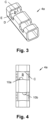
- Figs. 3 and 4 show the busbar holder 4a in more detail.
- Fig. 3 shows a perspective view of the busbar holder 4a and
- Fig. 4 shows a top view of the busbar holder 4a.
- the busbar holder 4a is a strut profile with a square pipe cross section and with cutouts B for the busbars L1..L3, L1', N. Accordingly, the busbar holder 4a can easily cut off from a standard profile and can be manufactured at low cost.
- the cutouts B form recesses for receiving the busbars L1..L3, L1', N. Beneficially, the cutouts B are made by a laser, but however other production techniques are applicable as well.
- a further advantage of the square pipe cross section is that the busbar holder 4a is comparably robust.
- the busbar holder 4a has two cutouts B, but other numbers of cutouts B are possible as well. So, different busbar arrangements with different numbers of busbars L1..L3, L1', N per busbar holder 4a can be realized easily. The only thing that varies in that respect is the number of cutouts B per busbar holder 4a and/or the length of the busbar holder 4a.
- Figs. 3 and 4 depict only one busbar holder 4a, the other busbar holders 4a, 4b preferably look the same. Accordingly, the technical disclosure, which is related to the busbar holder 4a, equally relates to the busbar holder 4b.
- Fig. 5 shows a front view of a cut out of the mounting system 1, concretely the busbar holder 4a being mounted in the lower holder rail 2a and with the busbars L1, L1' being received.
- a top region of the cutout B has convex or curved sections C on both sides which provide a number of advantages.
- inserting a busbar L1, L1' into the cutout B is eased because the risk for wedging is reduced, even if just a small gap is provided between the busbar L1, L1' and the busbar holder 4a.
- the surface of a busbar L1, L1' is not scratched when the busbar L1, L1' moves in longitudinal direction, in particular during assembly of the mounting system 1. This is particularly useful if the busbars L1, L1' are coated, because the coating is not scratched either.
- the convex or curved sections C can also have additionally chamfers or radii on the top and bottom edge in order to further improve the above effects.
- the busbars L1, L1' can be bent without causing excessive pressure on the vertical edges of the cutouts B. Such a bending for example can occur when high electromagnetic forces act on the busbars L1, L1'.
- this local plastification has two further effects, which positively influence the stability of the busbar holder 4a.
- the strength of the material of the busbar holder 4a is locally increased. This is an effect that is known from cold working and for example is used for cold rolled steel.
- the convex or curved sections C is flattened a bit so that the area effective for surface pressure is increased. In turn, surface pressure is reduced provided that the level of force is kept the same. So, these effects lead to a reduced risk for further plastification of the convex or curved sections C. In other words, an equilibrium is reached where the busbar holder 4a can withstand the forces within the mounting system 1 without further deformation. Basically, this adaption is made "automatically” or strictly speaking by means of the special shape on the sides of the cutout B.
- the cutout B has a flat or convex elevation D, in particular with rounded corners E on both sides of the elevation D.
- the holder rail 2a reaches over the elevations D of the busbar holder 4a in the mounted state of the mounting system 1, i.e. when the busbar holder 4a is mounted to the holder rail 2a. So, there is a height difference h between the elevation D and the busbar L1, L1' and between the elevation D and the upper edge of the holder rail 2a.
- the busbar L1, L1' can easily slide over the holder rail 2a because of the favorable friction coefficient between metal and plastic.
- the elevation D in the busbar holder 4a forms a hard stop for the busbar L1, L1'. So, a critical damage of the mounting system 1 can be avoided.
- the elevation D in the busbar holder 4a does also form a hard stop if the busbar holder 4a itself is deformed by excessive forces acting on the busbar L1, L1'. Such excessive forces can cause a deformation in a way that a longitudinal axis of the busbar holder 4a becomes arc shaped.
- busbar holder 4a like this is the case in the example shown in Figs. 5 and 6 .
- the busbars L1, L1' of a busbar holder 4a are exposed to different forces what leads to an asymmetric load on the busbar holder 4a. If the busbars L1, L1' are forced sidewards in different directions, a torque is induced in the busbar holder 4a. If this torque is very high, there is a risk that the fixing of the busbar holder 4a in the holder rail 2a fails what in turn causes said bending of the busbar holder 4a.
- the elevation or ridge D moves towards the busbar L1, L1'.
- the elevation D touches the busbar L1, L1', a further deformation of the busbar holder 4a is avoided or at least hindered.
- the elevation D does also act as a hard stop for the busbar holder 4a itself.
- the rounded corners E avoid the formation of cracks in the corners of the cutout B, not only but particularly in this scenario. So, the mounting system 1 is fault tolerant very much and even a failing or missing fixing of the busbar holder 4a does not lead to a collapse of the whole mounting system 1.
- the busbar holders 4a can be coated/painted in order to reduce friction between the busbar holders 4a and the busbars L1..L3, L1', N, to provide electrical isolation and/or to mark each electrical phase with a separate color.
- the busbar N can have blue color
- the busbar L1 can have brown color and so on.
- the base material of the busbar holder 4a can have a rough surface.
- Such a rough surface can be made by sandblasting for example, but also by means of a laser, which burns small pits into the surface of the base material of the busbar holder 4a.
- the same laser can be used, which is also used for cutting the cutout B. It is also possible, that only surfaces of the busbar holder 4a are provided with these pits which potentially get into contact with other parts.
- the edges of the cutouts B can be provided with pits to locally improve adhesion there.
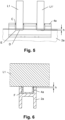
- Fig. 7 shows a top view of an exemplary holder rail 2a
- Fig. 8 shows a cross sectional view of the busbar holder 4a mounted to the holder rail 2a.
- the holder rail 2a can be a strut profile with an H cross section like this is the case in the Figs.
- the busbar holder 4a can be received in one opening of the "H” and means for mounting the busbar holders 4a, e.g. busbar holder screws 7a, 7b or rivets, can be received in the opposite opening of the "H".
- the heads of the mounting means e.g. the heads of the busbar holder screws 7a, 7b or rivets, are located in a groove so as to provide protection against unintentional contact by personnel.
- mounting means can be under voltage if they are made from metal, if no other measures are be taken to avoid that.
- a H cross section beneficially provides good stiffness against deflection. It should be noted that although the use of a H profile is beneficial, other shapes can be uses as well for the holder rail 2a. For example, the holder rails 2a can have a U cross section or a square pipe cross section.
- the H cross section of the holder rail 2a comprises grooves F on both sides of the bottom region facing the busbar holder 4a like this is shown in Figs. 6 and 8 .
- optional protrusions on the busbar holders 4a or on other equipment which can be fixed to the holder rail 2a, can reach into the grooves F.
- a busbar holder 4a or other equipment can be snapped in a holder rail 2a so that it does not fall out of the holder rail 2a unintentionally until the busbar holder 4a or other equipment is finally fixed to the holder rail 2a by mounting means, e.g. by busbar holder screws 7a, 7b or rivets.
- the mounting means for the busbar holder 4a are located at different distances b from and/or at different sides of a longitudinal axis K of the holder rail 2a, which said busbar holder 4a is fixed to like this is the case in the example shown in the Figs.
- Fig. 4 shows displaced busbar holder holes 10a, 10b
- Fig. 7 shows displaced holder rail holes 11a, 11b.
- the busbar holder 4a can be fixed to the holder rail 2a by mounting means, which are embodied as self-cutting busbar holder screws 7a, 7b like this is depicted in Fig. 8 .
- the use of self-cutting busbar holder screws 7a, 7b provides a number of advantages. First, no separate thread has to be cut into the busbar holder 4a because a self-cutting busbar holder screw 7a, 7b cuts the thread itself. Second, a self-cutting busbar holder screw 7a, 7b does not turn out on its own easily, even if the mounting system is exposed to vibrations like they occur within a switchgear. Hence, an additional screw locking can be omitted.
- self-cutting busbar holder screws 7a, 7b can be made shorter than screws, which are fixed by a nut. Accordingly, even if a busbar holder screw 7a, 7b falls off from the mounting system 1, the likelihood for an arc flash or short circuit caused by the busbar holder screws 7a, 7b is comparably low. This is based on the simple reason that a self-cutting busbar holder screw 7a, 7b is shorter than a screw fixed by a nut and cannot bridge large gaps between conductors under voltage.
- the self-cutting busbar holder screw 7a, 7b has a threaded portion G and an unthreaded portion J, wherein the outer diameter d1 of the threaded portion is smaller than the diameter d2 of the unthreaded portion J and wherein the threaded portion G is screwed into the busbar holder 4a and the unthreaded portion J is located within the holder rail 2a.
- the threaded portion G is screwed into a busbar holder hole 10a, 10b of the busbar holder 4a and the unthreaded portion J is located in a holder rail hole 11a, 11b of the holder rail 2a.
- a busbar holder screw 7a, 7b as defined hereinbefore can also be seen as a kind of a shoulder screw.
- the busbar holder 4a can be fixed to the holder rail 2ab by mounting means, which are embodied as rivets, in particular as snap in rivets.
- mounting means which are embodied as rivets, in particular as snap in rivets.
- the assembly of the mounting means always can happen from above, even if the busbar holder 4a, 4b is oriented in the upright position like this is the case for the lower busbar holder 4a.
- the rivet is inserted through the cutout D in the busbar holder 4a, and the head of the rivet is located within the busbar holder 4a in the mounted state.
- the rivet is inserted through a mounting hole 11a, 11b in the upper holder rail 2b. In neither case, the rivet can fall off by accident easily.
- the width of the busbar holder 4a is slightly below the inside dimension of the H cross section of the holder rail 2a. Accordingly, the busbar holder 4a can be mounted to the holder rail 2a easily. However, it could also be useful if the width of the busbar holder 4a is slightly above the inside dimension of the H cross section of the holder rail 2a.
- a busbar holder 4a is held in a holder rail 2a by friction then. So, the busbar holder 4a does not fall out of the holder rail 2a unintentionally until the busbar holder 4a is finally fixed to the holder rail 2a by mounting means, e.g. by busbar holder screws 7a, 7b or rivets.
- busbar holder 4a or other equipment shall be mounted to a holder rail 2a upside down like this is the case for the busbar holder 4b.
- the width of the busbar holders 4a, 4b matches the inside dimension of the H cross section, a rotation of the busbar holder 4a is avoided, even if just a single busbar holder screw 7a, 7b is used to fix the busbar holder 4a, 4b or even if mounting means for the busbar holder 4a, 4b, e.g. by busbar holder screws 7a, 7b or rivets, unintentionally fall of the mounting system 1 during operation. So, the mounting system 1 is fault tolerant very much, and the holder rail 2a acts as a kind of an assembly jig during assembly what eases manufacturing the mounting system 1.
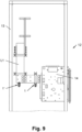
- Fig. 14 finally shows a side view of a cut out of an electrical switchgear 12, which comprises a number of busbars L1..L3, L1', N, a frame 13 and a switching device 14 electrically connected to the busbars L1..L3, L1', N.
- the busbars L1..L3, L1', N are held in position within the electrical switchgear 12.
- the mounting system 1 can be fixed to the frame 13 by means of the frame connectors 5a, 5b and the frame connector screws 9a, 9b.
- the busbar holders 4a, 4b are comparably robust and easily withstand the forces occurring in a switchgear 12. This is contrary to prior art solution where the holder rails 2a, 2b are made of metal and the busbar holders 4a, 4b are made of plastic.
- the contact surface between a busbar holder 4a, 4b and a holder rail 2a, 2b is comparably large, in addition those high forces can easily be transferred from the busbar holder 4a, 4b to the holder rail 2a, 2b, despite the fact that the holder rail 2a, 2b is made from plastic.
- the holder rail 2a, 2b provides electrical insulation and hence also avoids induced currents or eddy currents caused by the current through the busbars L1..L3, L1', N.
- a closed ferrous material loop around the busbars L1..L3, L1', N is avoided naturally by the non-ferrous material of the proposed holder rail 2a, 2b. This is not the case for prior art holder rails 2a, 2b made of metal where special measures have to be taken to avoid such a ferrous material loop and to avoid or at least limit said eddy currents.
Landscapes
- Engineering & Computer Science (AREA)
- Power Engineering (AREA)
- Installation Of Bus-Bars (AREA)
Applications Claiming Priority (1)
| Application Number | Priority Date | Filing Date | Title |
|---|---|---|---|
| GB2104971.3A GB2605624A (en) | 2021-04-08 | 2021-04-08 | Improved mounting system for busbars of an electrical switchgear |
Publications (2)
| Publication Number | Publication Date |
|---|---|
| EP4071950A1 EP4071950A1 (en) | 2022-10-12 |
| EP4071950B1 true EP4071950B1 (en) | 2025-05-14 |
Family
ID=75949627
Family Applications (1)
| Application Number | Title | Priority Date | Filing Date |
|---|---|---|---|
| EP22162748.2A Active EP4071950B1 (en) | 2021-04-08 | 2022-03-17 | Improved mounting system for busbars of an electrical switchgear |
Country Status (4)
| Country | Link |
|---|---|
| EP (1) | EP4071950B1 (pl) |
| CN (1) | CN115207779B (pl) |
| GB (1) | GB2605624A (pl) |
| PL (1) | PL4071950T3 (pl) |
Families Citing this family (1)
| Publication number | Priority date | Publication date | Assignee | Title |
|---|---|---|---|---|
| CN117498168B (zh) * | 2023-12-11 | 2024-06-11 | 安徽宇亮电气有限公司 | 一种母线安装架及配电系统 |
Family Cites Families (9)
| Publication number | Priority date | Publication date | Assignee | Title |
|---|---|---|---|---|
| US3315132A (en) * | 1964-10-09 | 1967-04-18 | Johnson & Phillips Australia P | Busbar power distribution systems |
| DE7031014U (de) * | 1970-08-19 | 1970-12-23 | Geyer Fa Christian | Trenner fuer sammelschienen. |
| DE3811458A1 (de) * | 1988-04-06 | 1989-10-19 | Loh Kg Rittal Werk | Halter mit strom-sammelschienen fuer ein sammelschienensystem |
| DE19503560C2 (de) * | 1995-02-03 | 1997-03-27 | Loh Kg Rittal Werk | Stromsammelschiene |
| FR2888998B1 (fr) * | 2005-07-22 | 2010-02-05 | Socomec Sa | Dispositif de support pour barres electriquement conductrices |
| DE202006005088U1 (de) * | 2006-03-28 | 2006-07-06 | Elg Elektrotechnology Ag | Sammelschienenhaltevorrichtung und Schaltschrank mit Sammelschienenhaltevorrichtung |
| KR100763167B1 (ko) * | 2006-08-25 | 2007-10-08 | 엘에스산전 주식회사 | 스위치기어의 모선연결장치 |
| US9558864B2 (en) * | 2012-08-14 | 2017-01-31 | Rockwell Automation Technologies, Inc. | Multi-drive common control bus connector system |
| DE102013114104A1 (de) * | 2013-12-16 | 2015-06-18 | Eaton Industries Austria Gmbh | Rahmen für einen Schaltschrank mit demontierbarer Bodenplatte für Verteilsammelschienen sowie Herstellungsverfahren für einen Schaltschrank |
-
2021
- 2021-04-08 GB GB2104971.3A patent/GB2605624A/en not_active Withdrawn
-
2022
- 2022-03-17 PL PL22162748.2T patent/PL4071950T3/pl unknown
- 2022-03-17 EP EP22162748.2A patent/EP4071950B1/en active Active
- 2022-03-25 CN CN202210305386.1A patent/CN115207779B/zh active Active
Also Published As
| Publication number | Publication date |
|---|---|
| EP4071950A1 (en) | 2022-10-12 |
| GB202104971D0 (en) | 2021-05-26 |
| CN115207779A (zh) | 2022-10-18 |
| PL4071950T3 (pl) | 2025-07-28 |
| GB2605624A (en) | 2022-10-12 |
| CN115207779B (zh) | 2025-06-10 |
Similar Documents
| Publication | Publication Date | Title |
|---|---|---|
| US7449635B2 (en) | Bus joint assembly | |
| AU2011242693B2 (en) | Improved press-fit busbar and busway employing same | |
| US9071028B2 (en) | Electrical connection between two busbars made of flat conductors and of an insulating layer disposed between the conductors | |
| CN102655032B (zh) | 电流导体 | |
| EP2948970B1 (en) | Arc runners suitable for dc molded case circuit breakers and related method | |
| EP2806517B1 (en) | Bus bar for electrical power distribution | |
| EP4071950B1 (en) | Improved mounting system for busbars of an electrical switchgear | |
| EP2589111B1 (en) | Spring-loaded compression electrical connector | |
| DK202170586A1 (en) | An electrical conductor for an electrical installation in a renewable energy facility | |
| KR101271779B1 (ko) | 고전압 전기기기의 도체 | |
| US20120019345A1 (en) | Compact modular fuse block with integrated fuse clearance | |
| EP4020716A1 (en) | Power feeder connector devices | |
| EP3108494B1 (en) | Switching assembly and interconnect assembly therefor | |
| US20120021658A1 (en) | Electrical connector for power conductors | |
| KR102175332B1 (ko) | 부스바 체결장치 | |
| CN1879281B (zh) | 包括接地导体的长定子和装有所述定子的磁悬浮铁路 | |
| EP1750342A1 (en) | Prefabricated leaktight duct member for the distribution of electrical power | |
| US9425568B2 (en) | Connector for conductor rails | |
| JP3660553B2 (ja) | 配電盤 | |
| CN212725607U (zh) | 铜排端子及应用所述铜排端子的铜排结构 | |
| US20030134544A1 (en) | Electrical connection element | |
| KR101991287B1 (ko) | 부스바 연결구조 | |
| CN109564829B (zh) | 用于高压开关设备的接触臂及其应用方法 | |
| KR200427088Y1 (ko) | 버스바조립체 | |
| JP2025169914A (ja) | 導電性コンタクトアセンブリ、モジュールコネクタ、接続アセンブリ、および機械的固定のための方法 |
Legal Events
| Date | Code | Title | Description |
|---|---|---|---|
| PUAI | Public reference made under article 153(3) epc to a published international application that has entered the european phase |
Free format text: ORIGINAL CODE: 0009012 |
|
| STAA | Information on the status of an ep patent application or granted ep patent |
Free format text: STATUS: THE APPLICATION HAS BEEN PUBLISHED |
|
| AK | Designated contracting states |
Kind code of ref document: A1 Designated state(s): AL AT BE BG CH CY CZ DE DK EE ES FI FR GB GR HR HU IE IS IT LI LT LU LV MC MK MT NL NO PL PT RO RS SE SI SK SM TR |
|
| STAA | Information on the status of an ep patent application or granted ep patent |
Free format text: STATUS: REQUEST FOR EXAMINATION WAS MADE |
|
| 17P | Request for examination filed |
Effective date: 20230321 |
|
| RBV | Designated contracting states (corrected) |
Designated state(s): AL AT BE BG CH CY CZ DE DK EE ES FI FR GB GR HR HU IE IS IT LI LT LU LV MC MK MT NL NO PL PT RO RS SE SI SK SM TR |
|
| P01 | Opt-out of the competence of the unified patent court (upc) registered |
Effective date: 20230521 |
|
| GRAP | Despatch of communication of intention to grant a patent |
Free format text: ORIGINAL CODE: EPIDOSNIGR1 |
|
| STAA | Information on the status of an ep patent application or granted ep patent |
Free format text: STATUS: GRANT OF PATENT IS INTENDED |
|
| RIC1 | Information provided on ipc code assigned before grant |
Ipc: H02B 1/21 20060101ALN20241203BHEP Ipc: H02G 5/02 20060101AFI20241203BHEP |
|
| INTG | Intention to grant announced |
Effective date: 20241219 |
|
| RIN1 | Information on inventor provided before grant (corrected) |
Inventor name: MUELLNER, DAVID Inventor name: GATTRINGER, THOMAS |
|
| GRAS | Grant fee paid |
Free format text: ORIGINAL CODE: EPIDOSNIGR3 |
|
| GRAA | (expected) grant |
Free format text: ORIGINAL CODE: 0009210 |
|
| STAA | Information on the status of an ep patent application or granted ep patent |
Free format text: STATUS: THE PATENT HAS BEEN GRANTED |
|
| AK | Designated contracting states |
Kind code of ref document: B1 Designated state(s): AL AT BE BG CH CY CZ DE DK EE ES FI FR GB GR HR HU IE IS IT LI LT LU LV MC MK MT NL NO PL PT RO RS SE SI SK SM TR |
|
| REG | Reference to a national code |
Ref country code: GB Ref legal event code: FG4D |
|
| REG | Reference to a national code |
Ref country code: CH Ref legal event code: EP |
|
| REG | Reference to a national code |
Ref country code: IE Ref legal event code: FG4D |
|
| REG | Reference to a national code |
Ref country code: DE Ref legal event code: R096 Ref document number: 602022014517 Country of ref document: DE |
|
| REG | Reference to a national code |
Ref country code: NL Ref legal event code: FP |
|
| PG25 | Lapsed in a contracting state [announced via postgrant information from national office to epo] |
Ref country code: ES Free format text: LAPSE BECAUSE OF FAILURE TO SUBMIT A TRANSLATION OF THE DESCRIPTION OR TO PAY THE FEE WITHIN THE PRESCRIBED TIME-LIMIT Effective date: 20250514 Ref country code: FI Free format text: LAPSE BECAUSE OF FAILURE TO SUBMIT A TRANSLATION OF THE DESCRIPTION OR TO PAY THE FEE WITHIN THE PRESCRIBED TIME-LIMIT Effective date: 20250514 Ref country code: PT Free format text: LAPSE BECAUSE OF FAILURE TO SUBMIT A TRANSLATION OF THE DESCRIPTION OR TO PAY THE FEE WITHIN THE PRESCRIBED TIME-LIMIT Effective date: 20250915 |
|
| REG | Reference to a national code |
Ref country code: LT Ref legal event code: MG9D |
|
| PG25 | Lapsed in a contracting state [announced via postgrant information from national office to epo] |
Ref country code: GR Free format text: LAPSE BECAUSE OF FAILURE TO SUBMIT A TRANSLATION OF THE DESCRIPTION OR TO PAY THE FEE WITHIN THE PRESCRIBED TIME-LIMIT Effective date: 20250815 |
|
| REG | Reference to a national code |
Ref country code: AT Ref legal event code: MK05 Ref document number: 1795656 Country of ref document: AT Kind code of ref document: T Effective date: 20250514 |
|
| PG25 | Lapsed in a contracting state [announced via postgrant information from national office to epo] |
Ref country code: BG Free format text: LAPSE BECAUSE OF FAILURE TO SUBMIT A TRANSLATION OF THE DESCRIPTION OR TO PAY THE FEE WITHIN THE PRESCRIBED TIME-LIMIT Effective date: 20250514 |
|
| PG25 | Lapsed in a contracting state [announced via postgrant information from national office to epo] |
Ref country code: HR Free format text: LAPSE BECAUSE OF FAILURE TO SUBMIT A TRANSLATION OF THE DESCRIPTION OR TO PAY THE FEE WITHIN THE PRESCRIBED TIME-LIMIT Effective date: 20250514 |
|
| PG25 | Lapsed in a contracting state [announced via postgrant information from national office to epo] |
Ref country code: AT Free format text: LAPSE BECAUSE OF FAILURE TO SUBMIT A TRANSLATION OF THE DESCRIPTION OR TO PAY THE FEE WITHIN THE PRESCRIBED TIME-LIMIT Effective date: 20250514 |
|
| PG25 | Lapsed in a contracting state [announced via postgrant information from national office to epo] |
Ref country code: RS Free format text: LAPSE BECAUSE OF FAILURE TO SUBMIT A TRANSLATION OF THE DESCRIPTION OR TO PAY THE FEE WITHIN THE PRESCRIBED TIME-LIMIT Effective date: 20250814 |
|
| PG25 | Lapsed in a contracting state [announced via postgrant information from national office to epo] |
Ref country code: IS Free format text: LAPSE BECAUSE OF FAILURE TO SUBMIT A TRANSLATION OF THE DESCRIPTION OR TO PAY THE FEE WITHIN THE PRESCRIBED TIME-LIMIT Effective date: 20250914 |
|
| PG25 | Lapsed in a contracting state [announced via postgrant information from national office to epo] |
Ref country code: LV Free format text: LAPSE BECAUSE OF FAILURE TO SUBMIT A TRANSLATION OF THE DESCRIPTION OR TO PAY THE FEE WITHIN THE PRESCRIBED TIME-LIMIT Effective date: 20250514 |
|
| PG25 | Lapsed in a contracting state [announced via postgrant information from national office to epo] |
Ref country code: SM Free format text: LAPSE BECAUSE OF FAILURE TO SUBMIT A TRANSLATION OF THE DESCRIPTION OR TO PAY THE FEE WITHIN THE PRESCRIBED TIME-LIMIT Effective date: 20250514 Ref country code: DK Free format text: LAPSE BECAUSE OF FAILURE TO SUBMIT A TRANSLATION OF THE DESCRIPTION OR TO PAY THE FEE WITHIN THE PRESCRIBED TIME-LIMIT Effective date: 20250514 |
|
| PG25 | Lapsed in a contracting state [announced via postgrant information from national office to epo] |
Ref country code: CZ Free format text: LAPSE BECAUSE OF FAILURE TO SUBMIT A TRANSLATION OF THE DESCRIPTION OR TO PAY THE FEE WITHIN THE PRESCRIBED TIME-LIMIT Effective date: 20250514 |
|
| PG25 | Lapsed in a contracting state [announced via postgrant information from national office to epo] |
Ref country code: EE Free format text: LAPSE BECAUSE OF FAILURE TO SUBMIT A TRANSLATION OF THE DESCRIPTION OR TO PAY THE FEE WITHIN THE PRESCRIBED TIME-LIMIT Effective date: 20250514 |
|
| PG25 | Lapsed in a contracting state [announced via postgrant information from national office to epo] |
Ref country code: SK Free format text: LAPSE BECAUSE OF FAILURE TO SUBMIT A TRANSLATION OF THE DESCRIPTION OR TO PAY THE FEE WITHIN THE PRESCRIBED TIME-LIMIT Effective date: 20250514 |
|
| PG25 | Lapsed in a contracting state [announced via postgrant information from national office to epo] |
Ref country code: IT Free format text: LAPSE BECAUSE OF FAILURE TO SUBMIT A TRANSLATION OF THE DESCRIPTION OR TO PAY THE FEE WITHIN THE PRESCRIBED TIME-LIMIT Effective date: 20250514 |
|
| REG | Reference to a national code |
Ref country code: DE Ref legal event code: R097 Ref document number: 602022014517 Country of ref document: DE |
|
| PGFP | Annual fee paid to national office [announced via postgrant information from national office to epo] |
Ref country code: NL Payment date: 20260219 Year of fee payment: 5 |
|
| PLBE | No opposition filed within time limit |
Free format text: ORIGINAL CODE: 0009261 |
|
| STAA | Information on the status of an ep patent application or granted ep patent |
Free format text: STATUS: NO OPPOSITION FILED WITHIN TIME LIMIT |
|
| REG | Reference to a national code |
Ref country code: CH Ref legal event code: L10 Free format text: ST27 STATUS EVENT CODE: U-0-0-L10-L00 (AS PROVIDED BY THE NATIONAL OFFICE) Effective date: 20260325 |
|
| PGFP | Annual fee paid to national office [announced via postgrant information from national office to epo] |
Ref country code: GB Payment date: 20260220 Year of fee payment: 5 |
|
| PGFP | Annual fee paid to national office [announced via postgrant information from national office to epo] |
Ref country code: NO Payment date: 20260223 Year of fee payment: 5 Ref country code: DE Payment date: 20260219 Year of fee payment: 5 |
|
| 26N | No opposition filed |
Effective date: 20260217 |