EP4071726A1 - Information processing system, position management method, information processing apparatus, and carrier medium - Google Patents
Information processing system, position management method, information processing apparatus, and carrier medium Download PDFInfo
- Publication number
- EP4071726A1 EP4071726A1 EP22162177.4A EP22162177A EP4071726A1 EP 4071726 A1 EP4071726 A1 EP 4071726A1 EP 22162177 A EP22162177 A EP 22162177A EP 4071726 A1 EP4071726 A1 EP 4071726A1
- Authority
- EP
- European Patent Office
- Prior art keywords
- image
- code image
- captured
- code
- information
- Prior art date
- Legal status (The legal status is an assumption and is not a legal conclusion. Google has not performed a legal analysis and makes no representation as to the accuracy of the status listed.)
- Pending
Links
Images


Classifications
-
- G—PHYSICS
- G06—COMPUTING; CALCULATING OR COUNTING
- G06F—ELECTRIC DIGITAL DATA PROCESSING
- G06F3/00—Input arrangements for transferring data to be processed into a form capable of being handled by the computer; Output arrangements for transferring data from processing unit to output unit, e.g. interface arrangements
- G06F3/12—Digital output to print unit, e.g. line printer, chain printer
- G06F3/1201—Dedicated interfaces to print systems
- G06F3/1202—Dedicated interfaces to print systems specifically adapted to achieve a particular effect
- G06F3/1203—Improving or facilitating administration, e.g. print management
- G06F3/1205—Improving or facilitating administration, e.g. print management resulting in increased flexibility in print job configuration, e.g. job settings, print requirements, job tickets
-
- G—PHYSICS
- G06—COMPUTING; CALCULATING OR COUNTING
- G06F—ELECTRIC DIGITAL DATA PROCESSING
- G06F3/00—Input arrangements for transferring data to be processed into a form capable of being handled by the computer; Output arrangements for transferring data from processing unit to output unit, e.g. interface arrangements
- G06F3/12—Digital output to print unit, e.g. line printer, chain printer
- G06F3/1201—Dedicated interfaces to print systems
- G06F3/1202—Dedicated interfaces to print systems specifically adapted to achieve a particular effect
- G06F3/1203—Improving or facilitating administration, e.g. print management
- G06F3/1208—Improving or facilitating administration, e.g. print management resulting in improved quality of the output result, e.g. print layout, colours, workflows, print preview
-
- G—PHYSICS
- G06—COMPUTING; CALCULATING OR COUNTING
- G06F—ELECTRIC DIGITAL DATA PROCESSING
- G06F3/00—Input arrangements for transferring data to be processed into a form capable of being handled by the computer; Output arrangements for transferring data from processing unit to output unit, e.g. interface arrangements
- G06F3/12—Digital output to print unit, e.g. line printer, chain printer
- G06F3/1201—Dedicated interfaces to print systems
- G06F3/1223—Dedicated interfaces to print systems specifically adapted to use a particular technique
- G06F3/1224—Client or server resources management
- G06F3/1226—Discovery of devices having required properties
-
- G—PHYSICS
- G06—COMPUTING; CALCULATING OR COUNTING
- G06F—ELECTRIC DIGITAL DATA PROCESSING
- G06F3/00—Input arrangements for transferring data to be processed into a form capable of being handled by the computer; Output arrangements for transferring data from processing unit to output unit, e.g. interface arrangements
- G06F3/12—Digital output to print unit, e.g. line printer, chain printer
- G06F3/1201—Dedicated interfaces to print systems
- G06F3/1223—Dedicated interfaces to print systems specifically adapted to use a particular technique
- G06F3/1237—Print job management
- G06F3/1242—Image or content composition onto a page
-
- G—PHYSICS
- G06—COMPUTING; CALCULATING OR COUNTING
- G06F—ELECTRIC DIGITAL DATA PROCESSING
- G06F3/00—Input arrangements for transferring data to be processed into a form capable of being handled by the computer; Output arrangements for transferring data from processing unit to output unit, e.g. interface arrangements
- G06F3/12—Digital output to print unit, e.g. line printer, chain printer
- G06F3/1201—Dedicated interfaces to print systems
- G06F3/1223—Dedicated interfaces to print systems specifically adapted to use a particular technique
- G06F3/1237—Print job management
- G06F3/1259—Print job monitoring, e.g. job status
-
- G—PHYSICS
- G06—COMPUTING; CALCULATING OR COUNTING
- G06F—ELECTRIC DIGITAL DATA PROCESSING
- G06F3/00—Input arrangements for transferring data to be processed into a form capable of being handled by the computer; Output arrangements for transferring data from processing unit to output unit, e.g. interface arrangements
- G06F3/12—Digital output to print unit, e.g. line printer, chain printer
- G06F3/1201—Dedicated interfaces to print systems
- G06F3/1223—Dedicated interfaces to print systems specifically adapted to use a particular technique
- G06F3/1237—Print job management
- G06F3/1273—Print job history, e.g. logging, accounting, tracking
-
- H—ELECTRICITY
- H04—ELECTRIC COMMUNICATION TECHNIQUE
- H04L—TRANSMISSION OF DIGITAL INFORMATION, e.g. TELEGRAPHIC COMMUNICATION
- H04L67/00—Network arrangements or protocols for supporting network services or applications
- H04L67/50—Network services
- H04L67/52—Network services specially adapted for the location of the user terminal
-
- H—ELECTRICITY
- H04—ELECTRIC COMMUNICATION TECHNIQUE
- H04W—WIRELESS COMMUNICATION NETWORKS
- H04W4/00—Services specially adapted for wireless communication networks; Facilities therefor
- H04W4/02—Services making use of location information
- H04W4/021—Services related to particular areas, e.g. point of interest [POI] services, venue services or geofences
-
- G—PHYSICS
- G06—COMPUTING; CALCULATING OR COUNTING
- G06V—IMAGE OR VIDEO RECOGNITION OR UNDERSTANDING
- G06V2201/00—Indexing scheme relating to image or video recognition or understanding
- G06V2201/06—Recognition of objects for industrial automation
Definitions
- Embodiments of the present disclosure relate to an information processing system, a location management method, an information processing apparatus, and a carrier medium.
- a technology is known in which a code image associated with a job is captured at each location associated with a work process, the job is recognized from the code image, and the work process associated with the captured location and the job recognized from the code image are managed in association with each other.
- a technology is known for managing a work process associated with a captured place and a job recognized from a code image in association with each other and providing information on the progress of a plurality of jobs including a plurality of work processes to a user (for example, see Japanese Unexamined Patent Application Publication No. 2020-024658 ).
- the plane position of a code image at each location associated with a work process is recognized from an image captured by a camera, the plane position of the code image may not be correctly recognized for the following reason.
- a camera generates a captured image by projecting an object existing in space onto a planar image. Therefore, when there is a variation in the height of the code image, it would be determined that code images at different plane positions existing on a straight line in the image capturing direction of the camera exist at the same plane position. Further, when there is a variation in the height of the code image, it would be determined that the code images existing at the same plane position exist at different plane positions.
- An object of an embodiment of the present invention is to provide an information processing system capable of stably managing a position of an object to be managed.
- an information processing system that includes an image capturing device, an information processing apparatus, a position information generation unit, and a management unit.
- the image capturing device is installed to capture an image of a range in which a position of an object to be managed is managed.
- the information processing apparatus recognizes a code image corresponding to the object from a captured image captured by the image capturing device and manage the position of the object.
- the position information generation unit generates spatial coordinate information of the code image based on a position of the code image recognized from the captured image, a size of the code image recognized from the captured image, and a size of a reference code image.
- the management unit manages the position of the object corresponding to the code image, with plane coordinate information of the code image corrected using the spatial coordinate information of the code image.
- a position management method to be executed by an information processing system that includes an image capturing device installed to capture an image of a range in which a position of an object to be managed is managed and an information processing apparatus to recognize a code image corresponding to the object from a captured image captured by the image capturing device and manage the position of the object.
- the method comprising generating spatial coordinate information of the code image based on a position of the code image recognized from the captured image, a size of the code image recognized from the captured image, and a size of a reference code image, and managing the position of the object corresponding to the code image, with plane coordinate information of the code image corrected using the spatial coordinate information of the code image.
- an information processing apparatus to recognize a code image corresponding to an object to be managed, from a captured image captured by an image capturing device installed to capture an image of a range in which a position of the object is managed, to manage the position of the object.
- the information processing apparatus includes a position information generation unit and a management unit.
- the position information generation unit generates spatial coordinate information of the code image based on a position of the code image recognized from the captured image, a size of the code image recognized from the captured image, and a size of a reference code image.
- the management unit manages the position of the object corresponding to the code image, with plane coordinate information of the code image corrected using the spatial coordinate information of the code image.
- a carrier medium carrying computer readable code for controlling a computer system to carry out the position management method.
- the position of an object to be managed can be stably managed.
- an information processing system that recognizes the position of a color code image, which is an example of a code image, to achieve management of a job operation process in a printing factory.
- embodiments of the present disclosure are not limited to the printing factory.
- embodiments of the present disclosure can also be applied to position recognition of various management objects such as position recognition of products in a factory and position recognition of delivery items in a collection place.
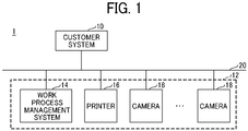
- FIG. 1 is a diagram illustrating a configuration of a job management system according to an embodiment of the present disclosure.
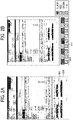
- FIG. 2 is an image diagram illustrating an example of a work instruction form used in the job management system according to the present embodiment.
- a customer system 10 a work process management system 14 a printer 16, and one or more cameras 18 are connected via a network 20 such as the Internet or a local area network (LAN) so as to be capable of data communications.
- a network 20 such as the Internet or a local area network (LAN) so as to be capable of data communications.
- LAN local area network
- the customer system 10 is an example of an existing system used by a customer and creates a work instruction form 800 for the customer system 10 in FIG. 2A in which a job identification (ID) is displayed.
- the job ID is an example of identification information for identifying a job.
- a barcode image 801 used on the customer system 10 is displayed.
- job ID may be displayed as a barcode image 801 in the work instruction form 800 for the customer system 10 or may be displayed as text.
- the customer system 10 provides a user with an existing function achieved by the work instruction form 800 for the customer system 10.
- the work process management system 14, the printer 16, and the one or more cameras 18 constitute at least part of an information processing system 12 that adds a new function to the work instruction form 800.
- the work process management system 14 manages the progress of a job including a plurality of work processes using a work instruction form 810 for the information processing system 12 to which a color code image 811 illustrated in FIG. 2B is assigned, as described below.
- the information processing system 12 can identify a job ID from the color code image 811 as described below.
- the printer 16 prints the work instruction form 810 for the information processing system 12.
- the work instruction form 810 for the information processing system 12 may be referred to as a work instruction form provided with a color code image.
- the cameras 18 are installed so as to be able to capture positions associated with work processes of a job in a printing factory. Note that the positions associated with the work processes of the job are places included in a range in which the position of an object to be managed is managed, for example, a place through which an object to be managed such as a printed matter passes by movement between the work processes, or a temporary storage place where an object to be managed is temporarily stored.
- a pan tilt zoom (PTZ) camera or an Internet protocol (IP) camera can be used as the camera 18.
- the PTZ camera is a camera capable of operating pan, tilt, and zoom functions via the network 20, and is a camera capable of transmitting a captured image or a captured moving image via the network 20.
- the IP camera is a camera that can be operated via the network 20 and can transmit a captured image or a captured moving image via the network 20.
- a captured image or a captured moving image captured by the camera 18 is transmitted to the work process management system 14 via the network 20.
- the camera 18 is an example of an image capturing device.
- the work instruction form 810 for the information processing system 12 is attached to a printed matter that is an example of an intermediate product or a material of a job corresponding to the work instruction form 810.
- the work instruction form 810 is attached on an object to be managed such as a printed matter that is easily captured by the cameras 18.
- the work process management system 14 recognizes a color code image of a work instruction form from images captured by the respective cameras 18, and thus manages the location of an object to be managed as described below.
- the work process management system 14 also manages the position of the object to be managed, and thus manages the progress of a work process of a job, that is, a state of a job.
- the work process management system 14 may manage a history of work processes of a job, and a captured image or a captured moving image representing a state when the work instruction form 810 is captured.
- the configuration of the job management system 1 illustrated in FIG. 1 is an example.
- the job management system 1 may include another system, or the work process management system 14 may be another name such as an information processing apparatus.
- the work process management system 14 may be implemented by a single server environment or by a plurality of server environments.
- the customer system 10 and the work process management system 14 are implemented by, for example, a computer 500 having a hardware configuration illustrated in FIG. 3 .
- FIG. 3 is a diagram illustrating a hardware configuration of a computer according to an embodiment of the present disclosure.
- a computer 500 of FIG. 3 includes, for example, an input device 501, a display device 502, an external interface (I/F) 503, a random access memory (RAM) 504, a read-only memory (ROM) 505, a central processing unit (CPU) 506, a communication I/F 507, a hard disk drive (HDD) 508 that are connected to each other by a bus B.
- I/F input device
- RAM random access memory
- ROM read-only memory
- CPU central processing unit
- HDD hard disk drive
- the input device 501 includes, for example, a keyboard, a mouse, and a touch screen and is used by a user to input various operation signals.
- the display device 502 includes, for example, a display and displays a processing result by the computer 500.
- the communication I/F 507 is an interface for connecting the computer 500 to various networks. Thus, the computer 500 can perform data transmission via the communication I/F 507.
- the HDD 508 is an example of a non-volatile storage device that stores programs and information.
- the stored programs and data include an operating system (OS), which is basic software for controlling the entire computer 500, and application software (hereinafter simply referred to as "application") for providing various functions on the OS.
- OS operating system
- application application software
- the computer 500 may include a drive device (for example, a solid state drive (SSD)) that uses a flash memory as a storage medium.
- SSD solid state drive
- the external I/F 503 is an interface with an external device.
- Examples of the external device include a recording medium 503a.
- Such a configuration allows the computer 500 to read from and write to the recording medium 503a via the external I/F 503.
- Examples of the recording medium 503a include flexible disks, compact discs (CDs), digital versatile discs (DVDs), secure digital (SD) memory cards, and universal serial bus (USB) memories.
- the ROM 505 is an example of a nonvolatile semiconductor memory (storage device) that can hold programs and data even when the power is turned off.
- the ROM 505 stores programs such as a basic input/output system (BIOS), an operating system (OS) setting, and a network setting, which are executed when the computer 500 is activated.
- the RAM 504 is an example of a volatile semiconductor memory (storage device) that temporarily stores programs and data.
- the CPU 506 is an arithmetic device that reads programs and information from a storage device such as the ROM 505 or the HDD 508 onto the RAM 504 and execute processing to achieve control and functions of the entire computer 500.
- the customer system 10 and the work process management system 14 can achieve various processes to be described below by a hardware configuration of a computer 500 as illustrated in FIG. 3 , for example.
- FIG. 4 is a diagram illustrating a functional configuration of the work process management system according to the present embodiment.
- the work process management system 14 illustrated in FIG. 4 includes a user interface (UI) unit 30, a setting unit 32, a job ID detection unit 34, a management unit 36, a color code image generation unit 38, a color-code-added work-instruction-form creation unit 40, a print instruction unit 42, a captured image acquisition unit 44, a color code recognition unit 46, a correction processing unit 48, a setting information storage unit 50, a color-code management table storage unit 52, and a job management table storage unit 54.
- the correction processing unit 48 includes a position information generation unit 60, a plane coordinate information correction unit 62, and a reference code image size calculation unit 64.
- the UI unit 30 controls the display of various screens such as various setting screens for receiving various necessary settings from a user and a map screen for visually displaying the location of an object to be managed as a marker.
- the setting unit 32 receives setting of setting information such as address setting information and camera setting information described below from a user, and controls a process of storing the setting information in the setting information storage unit 50.
- the setting unit 32 controls processing such as reception of designation of a map image including a range for managing the position of an object to be managed, provision of address identification information to squares of divided map images, and association with job process information.
- the setting unit 32 divides a captured image captured by each camera 18 into four divided images, and sets, to each divided image in the captured image, address identification information capable of specifying a square of a map image captured by each divided image.
- the setting unit 32 controls the processing such that the same address identification information is set even for divided images in captured images captured by different cameras 18 as long as the divided images capture the same squares.
- the same address identification information is set to the divided images of the cameras 18 capturing the same squares even if the cameras 18 are different.
- the job ID detection unit 34 detects a job ID displayed as a barcode image 801 or text in the work instruction form 800 for the customer system 10 in FIG. 2A .
- the management unit 36 stores and manages available color code IDs in the color-code management table storage unit 52.
- the management unit 36 selects an unused color code ID from the color-code management table storage unit 52.
- the management unit 36 manages the job ID detected by the job ID detection unit 34 and the selected color code ID in association with each other in the color-code management table storage unit 52.
- the management unit 36 also stores and manages job information corresponding to the job ID and the color code ID in the job management table storage unit 54.
- the job management table storage unit 54 manages progress information, history information, and the like of job work processes, and such information is used for visually displaying the location of an object as a marker on a map screen described below.
- the color code image generation unit 38 generates, for example, a color code image 811 illustrated in FIG. 2B from the color code ID provided from the management unit 36.
- the color-code-added work-instruction-form creation unit 40 creates the work instruction form 810 for the information processing system 12 to which the color code image 811 of FIG. 2B is attached, from the work instruction form 800 for the customer system 10 of FIG. 2A .
- the print instruction unit 42 instructs the printer 16 to print the work instruction form 810 for the information processing system 12 to which the color code image 811 of FIG. 2B is added.
- the captured image acquisition unit 44 acquires a captured image or a captured moving image from the cameras 18.
- the color code recognition unit 46 recognizes a color code image 811 included in the captured image or the captured moving image.
- the color code recognition unit 46 decodes a color code ID from the recognized color code image 811.
- the color code recognition unit 46 provides, for example, camera identification information for identifying the camera 18 that has captured the color code image 811, the decoded color code ID, and the captured image from which the color code image 811 has been recognized, to the correction processing unit 48.
- the correction processing unit 48 calculates the spatial position of the color code image 811 as described below and improves the detection accuracy of the plane position of the color code image 811 even when there is a variation in the height of the color code image 811 included in the captured image.
- the position information generation unit 60 is a position information generator that calculates the spatial position of the color code image 811 based on the size of the color code image 811 included in the captured image and a reference code size described below and generates information (spatial coordinate information) indicating the spatial position of the color code image 811, as described below.
- the plane coordinate information correction unit 62 corrects information (plane coordinate information) indicating the plane position of the color code image 811 recognized from the captured image, as described below, using the spatial coordinate information generated by the position information generating unit 60.
- the reference code image size calculation unit 64 calculates the size of a reference code image on a reference plane other than the center of the reference plane, as described below, from the size of the reference code image in a captured image obtained by capturing the reference code image placed at the center of the reference plane such as the ground with the camera 18.
- the correction processing unit 48 provides the management unit 36 with camera identification information for identifying the camera 18 that has captured the color code image 811, the decoded color code ID, the captured image from which the color code image 811 has been recognized, and plane coordinate information of the corrected color code image 811.
- the management unit 36 specifies the job ID corresponding to the decoded color code ID by referring to the color-code management table storage unit 52. In addition, by referring to the setting information storage unit 50, the management unit 36 can accurately specify the divided image of the camera 18 that has recognized the color code image from the plane coordinate information of the corrected color code image 811, and can specify the address identification information set in the specified divided image.
- the management unit 36 can update job status information, which is described below, managed by the job management table storage unit 54, based on the work process of the job corresponding to the divided image of the camera 18 that has captured the color code image and the job ID corresponding to the decoded color code ID.
- Each functional unit of the work process management system 14 and the customer system 10 may be mounted on an information processing apparatus or a server apparatus in a LAN, or may be configured as an information processing apparatus or a web server on the Internet and provided as a cloud service.
- the information processing apparatus may receive a request from a terminal device of a user via a network such as the Internet and return various screens, or may receive an input from a screen and execute setting.
- the information processing apparatus may also receive an image from an installed camera, recognize a code image, transmit a map screen to software such as a web browser of a terminal device, and update a position, a work situation, or the like of an object to be managed in real time using a bidirectional communication protocol.
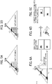
- FIGS. 5A and 5B are diagrams illustrating an example of a case where the position of a color code cannot be correctly recognized.
- FIG. 5A a color code image (1) exists.
- FIG. 5B illustrates a color code image (2).
- the color code image (1) is present at a lower position than the color code image (2).
- the color code images (1) and (2) are examples of color code images having a variation in height.
- FIGS. 5A and 5B illustrate both color code images (1) and (2) at the same time for ease of comparison, the color code images (1) and (2) are not present at the same time but one of the color code images (1) and (2) is present.
- the camera 18 would produce a captured image as if the color code images (1) and (2) are present at the same plane position. Accordingly, in the example of FIGS. 5A and 5B , when the plane positions of the color code images (1) and (2) are detected from the captured image, it would be recognized that the color code images (1) and (2) at different positions are present at the same plane position.
- FIGS. 6A, 6B, and 6C are diagrams illustrating an example of a method for correctly recognizing the position of a color code.
- the size of a color code image in a captured image obtained when the color code image placed at the center of a reference plane such as the ground is captured by the camera 18 is set as the size of the reference code image.
- the size of the color code image whose plane position is to be detected is detected from a captured image captured by the camera 18.
- the spatial position of the color code image is calculated from the size of the color code image, the size of the reference code image, the plane position of the color code image recognized from the captured image, and the height of the camera 18.
- the plane position of the color code image is corrected.
- FIG. 6A illustrates the relations among the size S 1 of the reference code image, the plane position X 1 of the color code image recognized from the captured image, the height H 1 of the camera 18 from the reference plane, the size S 2 of the color code image of the captured image, the plane position X 2 of the color code image to be calculated, and the height H 2 of the camera 18 with respect to the plane of the color code image to be calculated.
- the relation between the size S 1 of the reference code image, the size S 2 of the color code image of the captured image, the plane position X 1 of the color code image recognized from the captured image, and the plane position X 2 of the color code image to be calculated can be expressed by the following expression (1).
- Expression (3) for calculating the plane position X 2 of the color code image can be obtained from the above expression (1).
- Expression (4) for calculating the height H 2 of the camera 18 with reference to the plane of the color code image can be obtained from the above expression (2).
- X 2 S 1 / S 2 1 / 2 ⁇
- X 1 H 2 S 1 / S 2 1 / 2 ⁇ H 1
- the above expressions (1) to (4) are calculations in the X-axis direction, and the spatial position (spatial coordinates) of the color code image can be obtained by calculating the Y-axis direction in the same manner, and the plane position (plane coordinates) of the color code image can be corrected using the spatial coordinates.
- FIG. 6B illustrates that the reference code image of the size S 1 and the color code image of the size S 2 in FIG. 6A are captured at the same position on the captured image by the camera 18.
- the spatial coordinates of the color code image can be calculated based on the size S 1 of the reference code image and the size S 2 of the color code image, and can be corrected to the plane coordinates of the correct color code image.
- the plane position X 2 of the color code image and the height H 2 of the camera 18 with respect to the plane of the color code image can be calculated as follows.
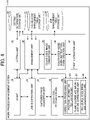
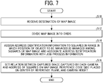
- FIG. 7 is a flowchart illustrating an example of a preparation process of an information processing system according to an embodiment of the present disclosure.
- a user uploads, for example, a map image of a printing factory including a range in which the position of an object to be managed is managed.
- the UI unit 30 of the work process management system 14 receives an operation for designating the map image from a user.
- the setting unit 32 receives designation of the map image by the user.
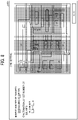
- the UI unit 30 may display a grid setting screen 1000 as illustrated in FIG. 8 , for example, and may receive a setting necessary for dividing the map image into squares from the user.
- FIG. 8 is an image diagram illustrating an example of the grid setting screen.
- the user can manually input the number of squares in grid by the number of columns ⁇ the number of rows.
- the number of squares can also be automatically set based on the capturing range (for example, 2 m ⁇ 2 m) of the camera 18 in response to the user's input of the width and depth of the floor or the floor space. For example, in the case of a floor of width 40 m ⁇ depth 20 m, squares of 20 columns ⁇ 10 rows are automatically assigned to the map image.
- the UI unit 30 may receive, from the user, editing of squares automatically assigned to the map image.
- the UI unit 30 additionally displays the grid so that the divided squares can be visually recognized.
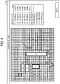
- step S14 the UI unit 30 displays, for example, an address setting screen 1100 as illustrated in FIG. 9 , and receives, from the user for each work process, setting of squares in the range in which the position of the object to be managed is managed among squares of the map image.
- FIG. 9 is an image diagram illustrating an example of the address setting screen.
- the user can select a work process to be associated with a square from a process list 1102 and designate, with a mouse or the like, a range of squares of a place where the work process is to be arranged.
- the range specification of squares corresponding to work processes A to G has been received from the user, and the range specification of the squares corresponding to the work process H is being received.
- the setting unit 32 assigns address identification information to squares of a place where a work process is arranged among squares of the map image and associates job process information for identifying the work process with the address identification information.
- a plurality of cameras 18 are installed at positions where the cameras 18 can capture squares (squares corresponding to the work processes A to L of the job) in a range in which the position of the object to be managed is managed among the squares of the map image.
- step S16 the UI unit 30 displays a camera setting screen 1200 as illustrated in FIG. 10 , for example, and allocates the camera 18 that captures the squares of each work process.
- FIG. 10 is an image diagram illustrating an example of a camera setting screen.
- a plurality of squares in which the work process is arranged are displayed in a camera arrangement field 1206.
- 16 squares of 4 ⁇ 4 in which the work process C is arranged are displayed as an example.
- the user selects cameras 18 to be arranged in a plurality of squares displayed in the camera arrangement field 1206 from a camera list 1204, and specifies the range of four squares of 2 ⁇ 2 in which the cameras 18 are arranged with a mouse or the like.
- the camera list 1204 may display cameras associated with other work processes in a grayed-out manner or with a completion mark(s).
- the camera setting screen 1200 of FIG. 10 includes an "automatically set cameras" key 1208, and the cameras 18 may be automatically arranged as illustrated in the camera arrangement field 1206 of FIG. 10 , for example, by receiving a pressing operation of a key 1208 from the user.
- the cameras 18 may be automatically arranged as illustrated in the camera arrangement field 1206 of FIG. 10 , for example, by receiving a pressing operation of a key 1208 from the user.
- nine cameras 18 are arranged.
- the number of cameras 18 to be arranged is (n-1) ⁇ (m-1) when the squares of the work process are n ⁇ m.
- the user operates the camera setting screen 1200 of FIG. 10 to set the address identification information of squares captured by the divided images of the plurality of cameras 18.
- the setting unit 32 can associate the camera identification information, the address identification information, and the job process information with, for example, each of the four divided image obtained by dividing the captured image of each of the cameras 18.
- step S16 the UI unit 30 receives setting of the reference code size placed at the center of the reference plane and the height of the camera 18.
- the setting of the reference code size and the height of the camera 18 is not limited to the timing of the step S16.
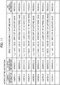
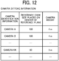
- the setting unit 32 can store the address setting information as illustrated in FIG. 11 and the camera setting information as illustrated in FIG. 12 in the setting information storage unit 50.
- FIG. 11 is a diagram illustrating an example of the configuration of address setting information according to the present embodiment.
- FIG. 12 is a diagram illustrating an example of the configuration of camera setting information according to the present embodiment.
- the address setting information in FIG. 11 associates camera identification information, address identification information, a region of a divided image in a captured image, and job process information with each other.
- the camera identification information is an example of identification information for identifying the camera 18.
- the address identification information is an example of identification information for identifying squares divided from the map image.
- the region of the divided image in the captured image is an example of identification information for identifying (or cutting out) a region of a divided image in the captured image captured by the camera 18.
- the job process information is an example of identification information for identifying a work process.
- the work process management system 14 can specify the address identification information of the squares captured by the divided images of the cameras 18 and the job process information for identifying the work process at the positions of the squares.
- a plurality of cameras 18 are set to redundantly capture squares to which the same address identification information is assigned, for example, as in an upper-right divided image of an image captured by the camera A and an upper-left divided image of an image captured by the camera B.
- camera identification information In the camera setting information of FIG. 12 , camera identification information, a reference code size placed at the center of a reference plane, and a camera height are associated with each other.
- the reference code size placed at the center of the reference plane is an example of information indicating the size of a reference code image captured in a captured image when the reference code image placed at the center of the reference plane such as the ground is captured with the camera 18 indicated by the camera identification information.
- the camera height is an example of information indicating the height of the camera 18 from the reference plane indicated by the camera identification information.
- work processes of a job in a printing factory include printing, cutting, folding, bookbinding, inspection, and temporary storage.
- the camera 18 is installed so as to be able to capture a range in which an object to be managed is placed in the work processes of the job. For example, it is assumed that a work instruction form with a color code image added thereto is attached to the object at a position where the object can be captured by the camera 18.
- the information processing system 12 attaches a work instruction form to which a color code image capable of specifying a job ID is added onto an object to be managed such as a printed matter and causes the camera 18 to capture the work instruction form, to manage the progress of a job including a plurality of work processes.
- the work instruction form to which the color code image is added is created, for example, as follows.
- the management unit 36 of the work process management system 14 selects a color code ID to be used from the color-code management table storage unit 52, and manages the selected color code ID and a job ID of a job for creating a work instruction form in association with each other.
- the color code image generation unit 38 generates a color code image from the color code ID associated with the job ID using a technique described in, for example, Japanese Unexamined Patent Application Publication No. 2017-199306 or Japanese Unexamined Patent Application Publication No. 2020-024658 .
- the color-code-added work-instruction-form creation unit 40 creates a work instruction form to which a color code image is added using the generated color code image.
- the print instruction unit 42 instructs the printer 16 to print the work instruction form (color-code-added work instruction form) to which the color code image is added.
- the printer 16 prints the work instruction form to which the color code image is added by an instruction from the print instruction unit 42.
- a work instruction form to which a color code image is added is attached on the printed matter.
- the work instruction form to which the color code image is added is captured by the cameras 18 in the work processes of the job.
- a color code image of a work instruction form attached on a printed matter, which is an example of an object to be managed is captured in work processes of a job.
- the job status of the job status information stored in the job management table storage unit 54 is updated by the processing illustrated in FIG. 13 when the work instruction form to which the color code image is added is captured by the cameras 18.
- FIG. 13 is a flowchart illustrating an example of a management process of the information processing system according to the present an embodiment.
- step S30 the captured image acquisition unit 44 of the work process management system 14 acquires a captured image from the camera 18.
- step S32 the color code recognition unit 46 performs recognition processing of a color code image from the captured image acquired by the captured image acquisition unit 44 in accordance with a procedure described in, for example, Japanese Unexamined Patent Application Publication No. 2017-199306 and Japanese Unexamined Patent Application Publication No. 2020-024658 or U.S. Patent Application Publication No. 2020-034592 which is incorporated by reference herein.
- the color code recognition unit 46 determines that the color code image is included in the captured image, and decodes the color code ID encoded in the color code image.
- the color code recognition unit 46 determines that a color code image is included in the captured image, processing of steps S36 to S42 is executed. If the color code recognition unit 46 does not determine that a color code image is included in the captured image, the processing of steps S36 to S42 is skipped.
- the color code recognition unit 46 determines that a color code image is included in the captured image, the color code recognition unit 46 provides, for example, camera identification information for identifying the camera 18 that has captured the color code image, the decoded color code ID, and the captured image from which the color code image has been recognized, to the correction processing unit 48.
- step S36 the correction processing unit 48 reads the address setting information and the camera setting information of the camera 18 that has captured the color code image, from the setting information storage unit 50.
- step S38 the correction processing unit 48 calculates spatial coordinates of the color code image using the method illustrated in FIG. 6 , and corrects the plane coordinates of the color code image using the spatial coordinates.
- the correction processing unit 48 provides the management unit 36 with camera identification information for identifying the camera 18 that has captured the color code image, the decoded color code ID, the captured image from which the color code image has been recognized, and plane coordinate information of the corrected color code image.
- step S40 the management unit 36 reads the address setting information of the camera 18 that has captured the color code image, from the setting information storage unit 50.
- the management unit 36 specifies the address identification information of the position (square) in the captured image at which the color code image is recognized using the plane coordinates of the corrected color code image.
- step S42 the management unit 36 updates, for example, the job status information as illustrated in FIG. 14 using the specified address identification information and job process information.
- FIG. 14 is a diagram illustrating an example of the configuration of job status information according to the present embodiment.
- the job status information illustrated in FIG. 14 manages address identification information, job process information, and status in association with each other.
- the job of the work instruction form in which the color code image is recognized in the step S32 is managed, using the job status information, as being in the position (squares) of the address identification information and the work process of the job process information that are associated with the position in the captured image in which the color code image has been recognized.
- FIG. 15 is a flowchart illustrating an example of a correction process of a position where a color code is recognized, according to the present embodiment.
- step S50 as described with reference to FIG. 6 , the position information generation unit 60 of the correction processing unit 48 calculates spatial coordinates of the recognized color code image based on the plane position of the color code image recognized from the captured image, the size of the recognized color code image, and the size of the reference code image.
- step S52 the plane coordinate information correction unit 62 corrects the plane coordinates of the color code image recognized from the captured image to a correct position as illustrated in FIGS. 6A to 6C by using the calculated spatial coordinates of the color code image.
- the correction processing unit 48 repeats the processing of steps S50 to S54 until the processing on all the color code images recognized from the captured image is completed.
- the size of the reference code image on the reference plane is calculated as illustrated in FIG. 16 from the size of the reference code image captured in the captured image.
- the captured image is obtained by capturing the reference code image placed at the center of the reference plane with the camera 18.
- FIG. 16 is a diagram illustrating an example of a method of calculating the size of a color code in a reference plane from the size of the color code placed at the center of the reference plane.
- FIG. 16 illustrates the relationship between the size S' of the reference code image at the center of the reference plane, the height H' of the camera 18 from the reference plane, and the size S 1 of another reference code image in the reference plane.
- the size S 1 of another reference code image in the reference plane can be calculated.
- FIG. 17 is a flowchart illustrating an example of the update processing of the job status information in the job management system according to the present embodiment.
- step S60 the management unit 36 refers to the color code management table stored in the color-code management table storage unit 52 and specifies the job ID corresponding to the color code ID of the color code image recognized.
- step S62 the management unit 36 updates the job status information of FIG. 14 so as to store the address identification information and the job process of the position (square) where the color code image is recognized, which is specified from the position of the plane coordinates of the corrected color code image, in association with the job ID specified in step S60.
- the management unit 36 repeats the processing of steps S60 to S64 until the processing on all the color code images recognized from the captured image is completed.
- FIG. 18 is a flowchart illustrating an example of a map display process of the job management system according to the present embodiment.
- the UI unit 30 displays a map image, for example, by receiving a display operation of the map image from the user.
- the map image is a map image of a printing factory or the like including a range in which the position of an object to be managed is managed, and is a map image designated in the preparation process.
- step S102 the UI unit 30 receives an input operation of a job ID of an object to be managed whose position is to be searched for from the user.
- step S104 the management unit 36 searches the job status information as illustrated in FIG. 14 , and specifies the address identification information and the job process information of the position where the object to be managed corresponding to the input job ID is present.
- step S106 the management unit 36 displays the location of the object to be managed corresponding to the job ID with a marker 1304 as illustrated in FIG. 19 , for example, in accordance with the address identification information and the job process information of the position where the object to be managed is present, which is specified in step S104.
- FIG. 19 is an image diagram illustrating an example of a map screen of the job management system according to the present embodiment.
- a map screen 1300 of FIG. 19 has a job ID input field 1302.
- the location of the job retrieved by the job ID is visually displayed on the map image by markers 1304.
- the map screen 1300 may not only display the current location of the job retrieved by the job ID with the markers 1304, but also visually display the locus of movement.
- the user can check the status of the object to be managed to which the work instruction form is attached and can track the object to be managed.
- FIG. 20 is an image diagram illustrating an example of another map screen of the job management system according to the present embodiment.
- FIG. 21 is an image diagram illustrating an example of another map screen of the job management system according to the present embodiment.
- the marker 1308 in FIG. 21 has a shape indicating that a plurality of jobs are present in the same square. Note that the marker 1308 may be displayed in the same color as the color of the color-code-added d work instruction form, the border color, or the like.
- a camera installation method in which the camera 18 is installed on a ceiling or the like and a range in which the position of an object is managed is captured from above is an example of upper installation.
- a camera 18 is installed on a wall or the like, and a camera installation method for capturing a range in which the position of an object is managed from a lateral direction is an example of lateral installation.
- FIGS. 22A and 22B are diagrams illustrating an example of a case where the position of a color code cannot be correctly recognized.
- FIG. 22A a color code image (1) and a color code image (2) are present at different heights in the same plane position.
- the color code image (1) and a color code image (3) are present at different plane positions with different heights.
- FIG. 22B illustrates both the color code images (1) and (3) at the same time for ease of comparison, the color code images (1) and (3) are not present at the same time, but one of the color code images (1) and (3) is present.
- the camera 18 would produce a captured image as if the color code images (1) and (2) are present at different plane positions. Accordingly, in the example of FIG. 22A , when the plane positions of the color code images (1) and (2) are detected from the captured image, it would be recognized that the color code images (1) and (2) at the same plane position are present at different plane positions.
- the camera 18 would produce a captured image as if the color code images (1) and (3) are present at the same plane position. Accordingly, in the example of FIG. 22B , when the plane positions of the color code images (1) and (3) are detected from the captured image, it would be recognized that the color code images (1) and (3) at different positions are present at the same plane position.
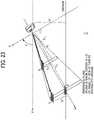
- FIG. 23 is a diagram illustrating an example of a method for correctly recognizing the position of a color code.
- the plane position of the color code image is detected in the same manner as in the method illustrated in FIG. 6 by projecting the plane position obtained from the captured image onto the real space.
- the detection values X 2 and H 2 are calculated using the method of the first embodiment, based on the size S 2 of the color code image of the captured image, the reference code size S 1 , and the plane position X 1 of the reference plane of the color code image recognized from the captured image.
- the plane position X' 2 of the color code image and the height H' 2 of the camera 18 can be calculated by converting the calculated detection values X 2 and H 2 into X' H' coordinates by the following expressions (10) and (11).
- H ′ 2 X 2 2 + H 2 2 1 / 2 ⁇ cos ⁇ + tan ⁇ 1 X 2 / H 2
- X ′ 2 X 2 2 + H 2 2 ⁇ H ′ 2 2 1 / 2
- the detection values X 2 and H 2 can be calculated as follows.
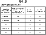
- FIG. 24 illustrates the camera setting information used in the second embodiment.
- FIG. 24 is a diagram illustrating an example of the configuration of camera setting information according to the present embodiment.
- "camera inclination ⁇ " is added as an item to the camera setting information of FIG. 12 .
- the item “camera inclination ⁇ " is an example of information indicating the inclination of the installed camera 18.
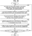
- FIG. 25 is a flowchart illustrating an example of a correction process of a position where a color code is recognized, according to the present embodiment.
- step S200 as described with reference to FIG. 23 , the position information generation unit 60 of the correction processing unit 48 calculates the distance H 1 from the camera 18 to the reference plane based on the installation conditions (camera height and camera inclination) of the camera setting information.
- step S202 the position information generation unit 60 calculates the reference code size S' of the reference plane, based on the plane position X 1 of the reference plane of the color code image recognized from the captured image and the reference code size S 1 of the reference plane.
- step S204 the position information generation unit 60 calculates the detection values X 2 and H 2 using the method of the first embodiment, based on the size S 2 of the color code image of the captured image, the reference code size S 1 , and the plane position X 1 of the reference plane of the color code image recognized from the captured image.
- step S206 the position information generation unit 60 can calculate the plane position X' 2 of the color code image and the height H' 2 of the camera 18 by converting the calculated detection values X 2 and H 2 into X'H' coordinates.
- step S208 the plane coordinate information correction unit 62 corrects the plane coordinates of the color code image recognized from the captured image to a correct position as illustrated in FIG. 23 by using the spatial coordinates of the color code image calculated in step S206.
- the correction processing unit 48 repeats the processing of steps S200 to S210 until the processing on all the color code images recognized from the captured image is completed.
- the positions of color code images that are superimposed at the same position and are present at different height positions can correctly recognized.
- a plurality of color code images of the object to be managed superimposed at the same position can be displayed in a superimposed manner or in a shaded manner.
- FIG. 26 is a diagram illustrating an example of the configuration of camera setting information according to the present embodiment.
- “camera installation method” is added as an item to the camera setting information of FIG. 24 .
- the item “camera installation method” is an example of information indicating whether the installed camera 18 is in the upper installation or the lateral installation. Note that the camera installation method may be automatically determined from the value of the camera inclination ⁇ .
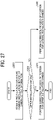
- FIG. 27 is a flowchart illustrating an example of a correction process of a position where a color code is recognized, according to the present embodiment.
- step S300 the position information generation unit 60 of the correction processing unit 48 determines whether the camera 18 that has captured a captured image is in the upper installation from the installation conditions (camera installation method) of the camera setting information in FIG. 26 .
- the position information generation unit 60 performs a position correction process (correction process of the first embodiment) for the upper installation camera in step S304. If the camera 18 is not the upper installation camera 18, the position information generation unit 60 performs a position correction process (correction process of the second embodiment) for the lateral installation camera in step S306.
- the upper installation camera 18 and the lateral installation camera 18 can be used in combination, and various places can be dealt with.
- the above-described first to third are technologies achieved by a work instruction form to which a code image to be attached to an object to be managed such as a printed matter is added.
- the technologies can be applied to a technology of a transport system represented by, for example, an automated guided vehicle (AGV).
- AGV automated guided vehicle
- a work instruction form to which a color code image is added is attached to the article, and the article being transported is captured by cameras 18, whereby the work process of the article being transported can be managed by a transport device.
- the transport system can also control the movement of the transport device that transports the article.
- embodiments of the present disclosure can also be applied to, for example, management of work processes of articles flowing on a belt conveyor. If the technology of the present embodiment is provided for managing work processes of articles flowing on a belt conveyor, the articles flowing on the belt conveyor can be tracked, and branching of the belt conveyor can also be controlled.
- the work process management system 14 is an example of an information processing apparatus according to an embodiment of the present disclosure.
- the present invention can be implemented in any convenient form, for example using dedicated hardware, or a mixture of dedicated hardware and software.
- the present invention may be implemented as computer software implemented by one or more networked processing apparatuses.
- the processing apparatuses include any suitably programmed apparatuses such as a general purpose computer, a personal digital assistant, a Wireless Application Protocol (WAP) or third-generation (3G)-compliant mobile telephone, and so on. Since the present invention can be implemented as software, each and every aspect of the present invention thus encompasses computer software implementable on a programmable device.
- the computer software can be provided to the programmable device using any conventional carrier medium (carrier means).
- the carrier medium includes a transient carrier medium such as an electrical, optical, microwave, acoustic or radio frequency signal carrying the computer code.
- transient medium is a Transmission Control Protocol/Internet Protocol (TCP/IP) signal carrying computer code over an IP network, such as the Internet.
- the carrier medium may also include a storage medium for storing processor readable code such as a floppy disk, a hard disk, a compact disc read-only memory (CD-ROM), a magnetic tape device, or a solid state memory device.
Abstract
An information processing system (12) includes an image capturing device (18), an information processing apparatus (14), a position information generation unit (60), and a management unit (36). The image capturing device captures an image of a range in which a position of an object is managed. The information processing apparatus recognizes a code image corresponding to the object from a captured image captured by the image capturing device and manage the position of the object. The position information generation unit generates spatial coordinate information of the code image based on a position of the code image recognized from the captured image, a size of the code image recognized from the captured image, and a size of a reference code image. The management unit manages the position of the object corresponding to the code image, with plane coordinate information of the code image corrected using the spatial coordinate information.
Description
- Embodiments of the present disclosure relate to an information processing system, a location management method, an information processing apparatus, and a carrier medium.
- Technologies are known for managing the progress of a job including a plurality of work processes by using a barcode or the like. For example, a technology is known in which a code image associated with a job is captured at each location associated with a work process, the job is recognized from the code image, and the work process associated with the captured location and the job recognized from the code image are managed in association with each other. In addition, a technology is known for managing a work process associated with a captured place and a job recognized from a code image in association with each other and providing information on the progress of a plurality of jobs including a plurality of work processes to a user (for example, see
Japanese Unexamined Patent Application Publication No. 2020-024658 - When the plane position of a code image at each location associated with a work process is recognized from an image captured by a camera, the plane position of the code image may not be correctly recognized for the following reason. For example, a camera generates a captured image by projecting an object existing in space onto a planar image. Therefore, when there is a variation in the height of the code image, it would be determined that code images at different plane positions existing on a straight line in the image capturing direction of the camera exist at the same plane position. Further, when there is a variation in the height of the code image, it would be determined that the code images existing at the same plane position exist at different plane positions.
- An object of an embodiment of the present invention is to provide an information processing system capable of stably managing a position of an object to be managed.
- According to an embodiment of the present disclosure, there is provided an information processing system that includes an image capturing device, an information processing apparatus, a position information generation unit, and a management unit. The image capturing device is installed to capture an image of a range in which a position of an object to be managed is managed. The information processing apparatus recognizes a code image corresponding to the object from a captured image captured by the image capturing device and manage the position of the object. The position information generation unit generates spatial coordinate information of the code image based on a position of the code image recognized from the captured image, a size of the code image recognized from the captured image, and a size of a reference code image. The management unit manages the position of the object corresponding to the code image, with plane coordinate information of the code image corrected using the spatial coordinate information of the code image.
- In another embodiment of the present disclosure, there is provided a position management method to be executed by an information processing system that includes an image capturing device installed to capture an image of a range in which a position of an object to be managed is managed and an information processing apparatus to recognize a code image corresponding to the object from a captured image captured by the image capturing device and manage the position of the object. The method comprising generating spatial coordinate information of the code image based on a position of the code image recognized from the captured image, a size of the code image recognized from the captured image, and a size of a reference code image, and managing the position of the object corresponding to the code image, with plane coordinate information of the code image corrected using the spatial coordinate information of the code image.
- In still another embodiment of the present disclosure, there is provided an information processing apparatus to recognize a code image corresponding to an object to be managed, from a captured image captured by an image capturing device installed to capture an image of a range in which a position of the object is managed, to manage the position of the object. The information processing apparatus includes a position information generation unit and a management unit. The position information generation unit generates spatial coordinate information of the code image based on a position of the code image recognized from the captured image, a size of the code image recognized from the captured image, and a size of a reference code image. The management unit manages the position of the object corresponding to the code image, with plane coordinate information of the code image corrected using the spatial coordinate information of the code image.
- In still yet another embodiment of the present disclosure, there is provided a carrier medium carrying computer readable code for controlling a computer system to carry out the position management method.
- According to an embodiment of the present disclosure, the position of an object to be managed can be stably managed.
- A more complete appreciation of the disclosure and many of the attendant advantages and features thereof can be readily obtained and understood from the following detailed description with reference to the accompanying drawings, wherein:
-
FIG. 1 is a diagram illustrating a configuration of a job management system according to an embodiment of the present disclosure; -
FIGS. 2A and 2B are image diagrams illustrating examples of a work instruction form used in the job management system ofFIG. 1 ; -
FIG. 3 is a diagram illustrating a hardware configuration of a computer according to an embodiment of the present disclosure; -
FIG. 4 is a diagram illustrating a functional configuration of a work process management system according to an embodiment of the present disclosure; -
FIGS. 5A and 5B are diagrams illustrating an example of a case where the position of a color code cannot be correctly recognized; -
FIGS. 6A, 6B, and 6C are diagrams illustrating an example of a method for correctly recognizing the position of a color code; -
FIG. 7 is a flowchart illustrating an example of a preparation process of an information processing system according to an embodiment of the present disclosure; -
FIG. 8 is an image diagram illustrating an example of a grid setting screen; -
FIG. 9 is an image diagram illustrating an example of an address setting screen; -
FIG. 10 is an image diagram illustrating an example of a camera setting screen; -
FIG. 11 is a diagram illustrating an example of the configuration of address setting information according to an embodiment of the present disclosure; -
FIG. 12 is a diagram illustrating an example of the configuration of camera setting information according to an embodiment of the present disclosure; -
FIG. 13 is a flowchart illustrating an example of a management process of an information processing system according to an embodiment of the present disclosure; -
FIG. 14 is a diagram illustrating an example of the configuration of job status information according to an embodiment of the present disclosure; -
FIG. 15 is a flowchart illustrating an example of a correction process of a position where a color code is recognized, according to an embodiment of the present disclosure; -
FIG. 16 is a diagram illustrating an example of a method of calculating the size of a color code in a reference plane from the size of the color code placed at the center of the reference plane, according to an embodiment of the present disclosure; -
FIG. 17 is a flowchart illustrating an example of update processing of job status information in a job management system according to an embodiment of the present disclosure; -
FIG. 18 is a flowchart illustrating an example of a map display process of a job management system according to an embodiment of the present disclosure; -
FIG. 19 is an image diagram illustrating an example of a map screen of a job management system according to an embodiment of the present disclosure; -
FIG. 20 is an image diagram illustrating an example of another map screen of a job management system according to an embodiment of the present disclosure; -
FIG. 21 is an image diagram illustrating an example of another map screen of a job management system according to an embodiment of the present disclosure; -
FIGS. 22A and 22B are diagrams illustrating an example of a case where the position of a color code cannot be correctly recognized; -
FIG. 23 is a diagram illustrating an example of a method for correctly recognizing the position of a color code; -
FIG. 24 is a diagram illustrating an example of the configuration of camera setting information according to an embodiment of the present disclosure; -
FIG. 25 is a flowchart illustrating an example of a correction process of a position where a color code is recognized, according to an embodiment of the present disclosure; -
FIG. 26 is a diagram illustrating an example of the configuration of camera setting information according to an embodiment of the present disclosure; and -
FIG. 27 is a flowchart illustrating an example of a correction process of a position where a color code is recognized, according to an embodiment of the present disclosure. - The accompanying drawings are intended to depict embodiments of the present invention and should not be interpreted to limit the scope thereof. The accompanying drawings are not to be considered as drawn to scale unless explicitly noted.
- The terminology used herein is for the purpose of describing particular embodiments only and is not intended to be limiting of the present invention. As used herein, the singular forms "a", "an" and "the" are intended to include the plural forms as well, unless the context clearly indicates otherwise.
- In describing embodiments illustrated in the drawings, specific terminology is employed for the sake of clarity. However, the disclosure of this specification is not intended to be limited to the specific terminology so selected and it is to be understood that each specific element includes all technical equivalents that have a similar function, operate in a similar manner, and achieve a similar result.
- Hereinafter, embodiments are described with reference to the drawings. In each drawing, the same configuration shares the same reference numeral and the overlapped description is omitted.
- Hereinafter, embodiments of the present disclosure are described with reference to the drawings. In an embodiment of the present disclosure, an information processing system is described that recognizes the position of a color code image, which is an example of a code image, to achieve management of a job operation process in a printing factory. However, embodiments of the present disclosure are not limited to the printing factory. For example, embodiments of the present disclosure can also be applied to position recognition of various management objects such as position recognition of products in a factory and position recognition of delivery items in a collection place.
-
FIG. 1 is a diagram illustrating a configuration of a job management system according to an embodiment of the present disclosure.FIG. 2 is an image diagram illustrating an example of a work instruction form used in the job management system according to the present embodiment. In ajob management system 1 ofFIG. 1 , acustomer system 10, a workprocess management system 14, aprinter 16, and one ormore cameras 18 are connected via anetwork 20 such as the Internet or a local area network (LAN) so as to be capable of data communications. - The
customer system 10 is an example of an existing system used by a customer and creates awork instruction form 800 for thecustomer system 10 inFIG. 2A in which a job identification (ID) is displayed. The job ID is an example of identification information for identifying a job. In thework instruction form 800 for thecustomer system 10 inFIG. 2A , abarcode image 801 used on thecustomer system 10 is displayed. - Note that the job ID may be displayed as a
barcode image 801 in thework instruction form 800 for thecustomer system 10 or may be displayed as text. Thecustomer system 10 provides a user with an existing function achieved by thework instruction form 800 for thecustomer system 10. - The work
process management system 14, theprinter 16, and the one ormore cameras 18 constitute at least part of aninformation processing system 12 that adds a new function to thework instruction form 800. The workprocess management system 14 manages the progress of a job including a plurality of work processes using awork instruction form 810 for theinformation processing system 12 to which acolor code image 811 illustrated inFIG. 2B is assigned, as described below. Theinformation processing system 12 can identify a job ID from thecolor code image 811 as described below. - The
printer 16 prints thework instruction form 810 for theinformation processing system 12. Thework instruction form 810 for theinformation processing system 12 may be referred to as a work instruction form provided with a color code image. Thecameras 18 are installed so as to be able to capture positions associated with work processes of a job in a printing factory. Note that the positions associated with the work processes of the job are places included in a range in which the position of an object to be managed is managed, for example, a place through which an object to be managed such as a printed matter passes by movement between the work processes, or a temporary storage place where an object to be managed is temporarily stored. - For example, a pan tilt zoom (PTZ) camera or an Internet protocol (IP) camera can be used as the
camera 18. The PTZ camera is a camera capable of operating pan, tilt, and zoom functions via thenetwork 20, and is a camera capable of transmitting a captured image or a captured moving image via thenetwork 20. The IP camera is a camera that can be operated via thenetwork 20 and can transmit a captured image or a captured moving image via thenetwork 20. A captured image or a captured moving image captured by thecamera 18 is transmitted to the workprocess management system 14 via thenetwork 20. Thecamera 18 is an example of an image capturing device. - In the
information processing system 12 in which a new function is added to thework instruction form 800, thework instruction form 810 for theinformation processing system 12 is attached to a printed matter that is an example of an intermediate product or a material of a job corresponding to thework instruction form 810. For example, thework instruction form 810 is attached on an object to be managed such as a printed matter that is easily captured by thecameras 18. - The work
process management system 14 recognizes a color code image of a work instruction form from images captured by therespective cameras 18, and thus manages the location of an object to be managed as described below. The workprocess management system 14 also manages the position of the object to be managed, and thus manages the progress of a work process of a job, that is, a state of a job. The workprocess management system 14 may manage a history of work processes of a job, and a captured image or a captured moving image representing a state when thework instruction form 810 is captured. - The configuration of the
job management system 1 illustrated inFIG. 1 is an example. For example, thejob management system 1 may include another system, or the workprocess management system 14 may be another name such as an information processing apparatus. The workprocess management system 14 may be implemented by a single server environment or by a plurality of server environments. - The
customer system 10 and the workprocess management system 14 are implemented by, for example, acomputer 500 having a hardware configuration illustrated inFIG. 3 . -
FIG. 3 is a diagram illustrating a hardware configuration of a computer according to an embodiment of the present disclosure. Acomputer 500 ofFIG. 3 includes, for example, aninput device 501, adisplay device 502, an external interface (I/F) 503, a random access memory (RAM) 504, a read-only memory (ROM) 505, a central processing unit (CPU) 506, a communication I/F 507, a hard disk drive (HDD) 508 that are connected to each other by a bus B. Note that theinput device 501 and thedisplay device 502 may be connected and used when necessary. - The
input device 501 includes, for example, a keyboard, a mouse, and a touch screen and is used by a user to input various operation signals. Thedisplay device 502 includes, for example, a display and displays a processing result by thecomputer 500. - The communication I/
F 507 is an interface for connecting thecomputer 500 to various networks. Thus, thecomputer 500 can perform data transmission via the communication I/F 507. - The
HDD 508 is an example of a non-volatile storage device that stores programs and information. The stored programs and data include an operating system (OS), which is basic software for controlling theentire computer 500, and application software (hereinafter simply referred to as "application") for providing various functions on the OS. Instead of theHDD 508, thecomputer 500 may include a drive device (for example, a solid state drive (SSD)) that uses a flash memory as a storage medium. - The external I/
F 503 is an interface with an external device. Examples of the external device include arecording medium 503a. Such a configuration allows thecomputer 500 to read from and write to therecording medium 503a via the external I/F 503. Examples of therecording medium 503a include flexible disks, compact discs (CDs), digital versatile discs (DVDs), secure digital (SD) memory cards, and universal serial bus (USB) memories. - The
ROM 505 is an example of a nonvolatile semiconductor memory (storage device) that can hold programs and data even when the power is turned off. TheROM 505 stores programs such as a basic input/output system (BIOS), an operating system (OS) setting, and a network setting, which are executed when thecomputer 500 is activated. TheRAM 504 is an example of a volatile semiconductor memory (storage device) that temporarily stores programs and data. - The
CPU 506 is an arithmetic device that reads programs and information from a storage device such as theROM 505 or theHDD 508 onto theRAM 504 and execute processing to achieve control and functions of theentire computer 500. Thecustomer system 10 and the workprocess management system 14 can achieve various processes to be described below by a hardware configuration of acomputer 500 as illustrated inFIG. 3 , for example. -
FIG. 4 is a diagram illustrating a functional configuration of the work process management system according to the present embodiment. In the diagram of the functional configuration illustrated inFIG. 4 , configurations unnecessary for the description of the present embodiment are omitted as appropriate. The workprocess management system 14 illustrated inFIG. 4 includes a user interface (UI)unit 30, asetting unit 32, a job ID detection unit 34, amanagement unit 36, a color codeimage generation unit 38, a color-code-added work-instruction-form creation unit 40, aprint instruction unit 42, a captured image acquisition unit 44, a colorcode recognition unit 46, acorrection processing unit 48, a settinginformation storage unit 50, a color-code managementtable storage unit 52, and a job managementtable storage unit 54. Thecorrection processing unit 48 includes a positioninformation generation unit 60, a plane coordinateinformation correction unit 62, and a reference code imagesize calculation unit 64. - The
UI unit 30 controls the display of various screens such as various setting screens for receiving various necessary settings from a user and a map screen for visually displaying the location of an object to be managed as a marker. The settingunit 32 receives setting of setting information such as address setting information and camera setting information described below from a user, and controls a process of storing the setting information in the settinginformation storage unit 50. For example, the settingunit 32 controls processing such as reception of designation of a map image including a range for managing the position of an object to be managed, provision of address identification information to squares of divided map images, and association with job process information. - The setting
unit 32 divides a captured image captured by eachcamera 18 into four divided images, and sets, to each divided image in the captured image, address identification information capable of specifying a square of a map image captured by each divided image. The settingunit 32 controls the processing such that the same address identification information is set even for divided images in captured images captured bydifferent cameras 18 as long as the divided images capture the same squares. As described above, the same address identification information is set to the divided images of thecameras 18 capturing the same squares even if thecameras 18 are different. For example, the job ID detection unit 34 detects a job ID displayed as abarcode image 801 or text in thework instruction form 800 for thecustomer system 10 inFIG. 2A . - The
management unit 36 stores and manages available color code IDs in the color-code managementtable storage unit 52. Themanagement unit 36 selects an unused color code ID from the color-code managementtable storage unit 52. Themanagement unit 36 manages the job ID detected by the job ID detection unit 34 and the selected color code ID in association with each other in the color-code managementtable storage unit 52. - The
management unit 36 also stores and manages job information corresponding to the job ID and the color code ID in the job managementtable storage unit 54. The job managementtable storage unit 54 manages progress information, history information, and the like of job work processes, and such information is used for visually displaying the location of an object as a marker on a map screen described below. - The color code
image generation unit 38 generates, for example, acolor code image 811 illustrated inFIG. 2B from the color code ID provided from themanagement unit 36. - For example, the color-code-added work-instruction-
form creation unit 40 creates thework instruction form 810 for theinformation processing system 12 to which thecolor code image 811 ofFIG. 2B is attached, from thework instruction form 800 for thecustomer system 10 ofFIG. 2A . For example, theprint instruction unit 42 instructs theprinter 16 to print thework instruction form 810 for theinformation processing system 12 to which thecolor code image 811 ofFIG. 2B is added. - The captured image acquisition unit 44 acquires a captured image or a captured moving image from the
cameras 18. The colorcode recognition unit 46 recognizes acolor code image 811 included in the captured image or the captured moving image. The colorcode recognition unit 46 decodes a color code ID from the recognizedcolor code image 811. The colorcode recognition unit 46 provides, for example, camera identification information for identifying thecamera 18 that has captured thecolor code image 811, the decoded color code ID, and the captured image from which thecolor code image 811 has been recognized, to thecorrection processing unit 48. - The
correction processing unit 48 calculates the spatial position of thecolor code image 811 as described below and improves the detection accuracy of the plane position of thecolor code image 811 even when there is a variation in the height of thecolor code image 811 included in the captured image. - The position
information generation unit 60 is a position information generator that calculates the spatial position of thecolor code image 811 based on the size of thecolor code image 811 included in the captured image and a reference code size described below and generates information (spatial coordinate information) indicating the spatial position of thecolor code image 811, as described below. - The plane coordinate
information correction unit 62 corrects information (plane coordinate information) indicating the plane position of thecolor code image 811 recognized from the captured image, as described below, using the spatial coordinate information generated by the positioninformation generating unit 60. The reference code imagesize calculation unit 64 calculates the size of a reference code image on a reference plane other than the center of the reference plane, as described below, from the size of the reference code image in a captured image obtained by capturing the reference code image placed at the center of the reference plane such as the ground with thecamera 18. - The
correction processing unit 48 provides themanagement unit 36 with camera identification information for identifying thecamera 18 that has captured thecolor code image 811, the decoded color code ID, the captured image from which thecolor code image 811 has been recognized, and plane coordinate information of the correctedcolor code image 811. - The
management unit 36 specifies the job ID corresponding to the decoded color code ID by referring to the color-code managementtable storage unit 52. In addition, by referring to the settinginformation storage unit 50, themanagement unit 36 can accurately specify the divided image of thecamera 18 that has recognized the color code image from the plane coordinate information of the correctedcolor code image 811, and can specify the address identification information set in the specified divided image. - The
management unit 36 can update job status information, which is described below, managed by the job managementtable storage unit 54, based on the work process of the job corresponding to the divided image of thecamera 18 that has captured the color code image and the job ID corresponding to the decoded color code ID. - Each functional unit of the work
process management system 14 and thecustomer system 10 may be mounted on an information processing apparatus or a server apparatus in a LAN, or may be configured as an information processing apparatus or a web server on the Internet and provided as a cloud service. For example, the information processing apparatus may receive a request from a terminal device of a user via a network such as the Internet and return various screens, or may receive an input from a screen and execute setting. The information processing apparatus may also receive an image from an installed camera, recognize a code image, transmit a map screen to software such as a web browser of a terminal device, and update a position, a work situation, or the like of an object to be managed in real time using a bidirectional communication protocol. - First, a description is given of an example in which the plane position of the
color code image 811 cannot be correctly recognized when the position of thecolor code image 811 is recognized from a captured image captured by thecamera 18.FIGS. 5A and 5B are diagrams illustrating an example of a case where the position of a color code cannot be correctly recognized. - In
FIG. 5A , a color code image (1) exists.FIG. 5B illustrates a color code image (2). The color code image (1) is present at a lower position than the color code image (2). The color code images (1) and (2) are examples of color code images having a variation in height. AlthoughFIGS. 5A and 5B illustrate both color code images (1) and (2) at the same time for ease of comparison, the color code images (1) and (2) are not present at the same time but one of the color code images (1) and (2) is present. - As illustrated in
FIGS. 5A and 5B , in a case where the color code images (1) and (2) are present on a straight line in the image capturing direction even when the color code images (1) and (2) are present at different spatial positions, thecamera 18 would produce a captured image as if the color code images (1) and (2) are present at the same plane position. Accordingly, in the example ofFIGS. 5A and 5B , when the plane positions of the color code images (1) and (2) are detected from the captured image, it would be recognized that the color code images (1) and (2) at different positions are present at the same plane position. - For this reason, in the present embodiment, the plane position of the color code image is accurately detected by the method illustrated in
FIGS. 6A, 6B, and 6C. FIGS. 6A, 6B, and 6C are diagrams illustrating an example of a method for correctly recognizing the position of a color code. In the method illustrated inFIGS. 6A, 6B, and 6C , the size of a color code image in a captured image obtained when the color code image placed at the center of a reference plane such as the ground is captured by thecamera 18 is set as the size of the reference code image. In the method illustrated inFIGS. 6A, 6B, and 6C , the size of the color code image whose plane position is to be detected is detected from a captured image captured by thecamera 18. - In the method illustrated in
FIGS. 6A, 6B, and 6C , as described below, the spatial position of the color code image is calculated from the size of the color code image, the size of the reference code image, the plane position of the color code image recognized from the captured image, and the height of thecamera 18. Thus, the plane position of the color code image is corrected. -
FIG. 6A illustrates the relations among the size S1 of the reference code image, the plane position X1 of the color code image recognized from the captured image, the height H1 of thecamera 18 from the reference plane, the size S2 of the color code image of the captured image, the plane position X2 of the color code image to be calculated, and the height H2 of thecamera 18 with respect to the plane of the color code image to be calculated. - In the example of
FIG. 6 , using the similarity relation, the relation between the size S1 of the reference code image, the size S2 of the color code image of the captured image, the plane position X1 of the color code image recognized from the captured image, and the plane position X2 of the color code image to be calculated can be expressed by the following expression (1). - The relation between the size S1 of the reference code image, the size S2 of the color code image of the captured image, the height H1 of the
camera 18 from the reference plane, and the height H2 of thecamera 18 with respect to the plane of the color code image to be calculated can be expressed by the following expression (2).

- Expression (3) for calculating the plane position X2 of the color code image can be obtained from the above expression (1). Expression (4) for calculating the height H2 of the
camera 18 with reference to the plane of the color code image can be obtained from the above expression (2).

- Note that the above expressions (1) to (4) are calculations in the X-axis direction, and the spatial position (spatial coordinates) of the color code image can be obtained by calculating the Y-axis direction in the same manner, and the plane position (plane coordinates) of the color code image can be corrected using the spatial coordinates.
-
FIG. 6B illustrates that the reference code image of the size S1 and the color code image of the size S2 inFIG. 6A are captured at the same position on the captured image by thecamera 18. In the present embodiment, for example, as illustrated inFIGS. 6C and 6D, the spatial coordinates of the color code image can be calculated based on the size S1 of the reference code image and the size S2 of the color code image, and can be corrected to the plane coordinates of the correct color code image. - For example, in the example of
FIG. 6A , when the height H1 of thecamera 18 from the reference plane is 4 m, the size S2 of the color code image of the captured image is 400, the plane position X1 of the color code image recognized from the captured image is 2 m, and the size S1 of the reference code image is 100, the plane position X2 of the color code image and the height H2 of thecamera 18 with respect to the plane of the color code image can be calculated as follows.

- Hereinafter, a description is given of a preparation process necessary for achieving the management of the work processes of the job in the printing factory by grasping the position of the color code image in the
job management system 1 according to the present embodiment and a management process for achieving the management of the work processes of the job in the printing factory by grasping the position of the color code image. -
FIG. 7 is a flowchart illustrating an example of a preparation process of an information processing system according to an embodiment of the present disclosure. In step S10, a user uploads, for example, a map image of a printing factory including a range in which the position of an object to be managed is managed. TheUI unit 30 of the workprocess management system 14 receives an operation for designating the map image from a user. The settingunit 32 receives designation of the map image by the user. - In step S12, the
UI unit 30 may display agrid setting screen 1000 as illustrated inFIG. 8 , for example, and may receive a setting necessary for dividing the map image into squares from the user. -
FIG. 8 is an image diagram illustrating an example of the grid setting screen. On thegrid setting screen 1000 illustrated inFIG. 8 , the user can manually input the number of squares in grid by the number of columns × the number of rows. In thegrid setting screen 1000 illustrated inFIG. 8 , the number of squares can also be automatically set based on the capturing range (for example, 2 m × 2 m) of thecamera 18 in response to the user's input of the width and depth of the floor or the floor space. For example, in the case of a floor of width 40 m × depth 20 m, squares of 20 columns × 10 rows are automatically assigned to the map image. TheUI unit 30 may receive, from the user, editing of squares automatically assigned to the map image. By the user's input to thegrid setting screen 1000, for example, as illustrated in the map image of thegrid setting screen 1000 ofFIG. 8 , theUI unit 30 additionally displays the grid so that the divided squares can be visually recognized. - In step S14, the
UI unit 30 displays, for example, anaddress setting screen 1100 as illustrated inFIG. 9 , and receives, from the user for each work process, setting of squares in the range in which the position of the object to be managed is managed among squares of the map image. -
FIG. 9 is an image diagram illustrating an example of the address setting screen. For example, in theaddress setting screen 1100 ofFIG. 9 , the user can select a work process to be associated with a square from aprocess list 1102 and designate, with a mouse or the like, a range of squares of a place where the work process is to be arranged. For example, in the example of the map image ofFIG. 9 , the range specification of squares corresponding to work processes A to G has been received from the user, and the range specification of the squares corresponding to the work process H is being received. The settingunit 32 assigns address identification information to squares of a place where a work process is arranged among squares of the map image and associates job process information for identifying the work process with the address identification information. - It is assumed that a plurality of
cameras 18 are installed at positions where thecameras 18 can capture squares (squares corresponding to the work processes A to L of the job) in a range in which the position of the object to be managed is managed among the squares of the map image. - In step S16, the
UI unit 30 displays acamera setting screen 1200 as illustrated inFIG. 10 , for example, and allocates thecamera 18 that captures the squares of each work process.FIG. 10 is an image diagram illustrating an example of a camera setting screen. - For example, in the
camera setting screen 1200 ofFIG. 10 , when the user selects one work process from aprocess selection field 1202, a plurality of squares in which the work process is arranged are displayed in acamera arrangement field 1206. InFIG. 10 ,16 squares of 4 × 4 in which the work process C is arranged are displayed as an example. - The user selects
cameras 18 to be arranged in a plurality of squares displayed in thecamera arrangement field 1206 from acamera list 1204, and specifies the range of four squares of 2 × 2 in which thecameras 18 are arranged with a mouse or the like. Note that thecamera list 1204 may display cameras associated with other work processes in a grayed-out manner or with a completion mark(s). - For example, in the
camera setting screen 1200 ofFIG. 10 , among squares of address identification information "1" to "16" associated with the work process of "process C", "camera b" is arranged in address identification information "1", "2", "5", and "6", "camera c" is arranged in address identification information "2", "3", "6", and "7", "camera d" is arranged in address identification information "3", "4", "7", and "8", and "camera e" is arranged in address identification information "5", "6", "9", and "10". - Note that the
camera setting screen 1200 ofFIG. 10 includes an "automatically set cameras" key 1208, and thecameras 18 may be automatically arranged as illustrated in thecamera arrangement field 1206 ofFIG. 10 , for example, by receiving a pressing operation of a key 1208 from the user. In the case of the work process of 16 squares of 4 × 4 illustrated in thecamera arrangement field 1206 ofFIG. 10 , ninecameras 18 are arranged. The number ofcameras 18 to be arranged is (n-1) × (m-1) when the squares of the work process are n × m. - The user operates the
camera setting screen 1200 ofFIG. 10 to set the address identification information of squares captured by the divided images of the plurality ofcameras 18. The settingunit 32 can associate the camera identification information, the address identification information, and the job process information with, for example, each of the four divided image obtained by dividing the captured image of each of thecameras 18. - In step S16, the
UI unit 30 receives setting of the reference code size placed at the center of the reference plane and the height of thecamera 18. The setting of the reference code size and the height of thecamera 18 is not limited to the timing of the step S16. - Through the processing of the flowchart of
FIG. 7 , the settingunit 32 can store the address setting information as illustrated inFIG. 11 and the camera setting information as illustrated inFIG. 12 in the settinginformation storage unit 50.FIG. 11 is a diagram illustrating an example of the configuration of address setting information according to the present embodiment.FIG. 12 is a diagram illustrating an example of the configuration of camera setting information according to the present embodiment. - The address setting information in
FIG. 11 associates camera identification information, address identification information, a region of a divided image in a captured image, and job process information with each other. The camera identification information is an example of identification information for identifying thecamera 18. The address identification information is an example of identification information for identifying squares divided from the map image. The region of the divided image in the captured image is an example of identification information for identifying (or cutting out) a region of a divided image in the captured image captured by thecamera 18. The job process information is an example of identification information for identifying a work process. - Using the address setting information illustrated in
FIG. 11 , the workprocess management system 14 can specify the address identification information of the squares captured by the divided images of thecameras 18 and the job process information for identifying the work process at the positions of the squares. In the address setting information ofFIG. 11 , a plurality ofcameras 18 are set to redundantly capture squares to which the same address identification information is assigned, for example, as in an upper-right divided image of an image captured by the camera A and an upper-left divided image of an image captured by the camera B. - In the camera setting information of
FIG. 12 , camera identification information, a reference code size placed at the center of a reference plane, and a camera height are associated with each other. The reference code size placed at the center of the reference plane is an example of information indicating the size of a reference code image captured in a captured image when the reference code image placed at the center of the reference plane such as the ground is captured with thecamera 18 indicated by the camera identification information. The camera height is an example of information indicating the height of thecamera 18 from the reference plane indicated by the camera identification information. - For example, work processes of a job in a printing factory include printing, cutting, folding, bookbinding, inspection, and temporary storage. The
camera 18 is installed so as to be able to capture a range in which an object to be managed is placed in the work processes of the job. For example, it is assumed that a work instruction form with a color code image added thereto is attached to the object at a position where the object can be captured by thecamera 18. - The
information processing system 12 according to the present embodiment attaches a work instruction form to which a color code image capable of specifying a job ID is added onto an object to be managed such as a printed matter and causes thecamera 18 to capture the work instruction form, to manage the progress of a job including a plurality of work processes. - The work instruction form to which the color code image is added is created, for example, as follows. The
management unit 36 of the workprocess management system 14 selects a color code ID to be used from the color-code managementtable storage unit 52, and manages the selected color code ID and a job ID of a job for creating a work instruction form in association with each other. - The color code
image generation unit 38 generates a color code image from the color code ID associated with the job ID using a technique described in, for example,Japanese Unexamined Patent Application Publication No. 2017-199306 Japanese Unexamined Patent Application Publication No. 2020-024658 form creation unit 40 creates a work instruction form to which a color code image is added using the generated color code image. - The
print instruction unit 42 instructs theprinter 16 to print the work instruction form (color-code-added work instruction form) to which the color code image is added. Theprinter 16 prints the work instruction form to which the color code image is added by an instruction from theprint instruction unit 42. - For example, in a printing factory, after a printed matter is output by work processes of printing, a work instruction form to which a color code image is added is attached on the printed matter. After being attached on the printed matter which is an example of the object to be managed, the work instruction form to which the color code image is added is captured by the
cameras 18 in the work processes of the job. As described above, in thejob management system 1 according to the present embodiment, a color code image of a work instruction form attached on a printed matter, which is an example of an object to be managed, is captured in work processes of a job. - In the
job management system 1 according to the present embodiment, the job status of the job status information stored in the job managementtable storage unit 54 is updated by the processing illustrated inFIG. 13 when the work instruction form to which the color code image is added is captured by thecameras 18. -
FIG. 13 is a flowchart illustrating an example of a management process of the information processing system according to the present an embodiment. In step S30, the captured image acquisition unit 44 of the workprocess management system 14 acquires a captured image from thecamera 18. - In step S32, the color
code recognition unit 46 performs recognition processing of a color code image from the captured image acquired by the captured image acquisition unit 44 in accordance with a procedure described in, for example,Japanese Unexamined Patent Application Publication No. 2017-199306 Japanese Unexamined Patent Application Publication No. 2020-024658 U.S. Patent Application Publication No. 2020-034592 which is incorporated by reference herein. When recognizing the color code image in step S34, the colorcode recognition unit 46 determines that the color code image is included in the captured image, and decodes the color code ID encoded in the color code image. - When the color
code recognition unit 46 determines that a color code image is included in the captured image, processing of steps S36 to S42 is executed. If the colorcode recognition unit 46 does not determine that a color code image is included in the captured image, the processing of steps S36 to S42 is skipped. When determining that a color code image is included in the captured image, the colorcode recognition unit 46 provides, for example, camera identification information for identifying thecamera 18 that has captured the color code image, the decoded color code ID, and the captured image from which the color code image has been recognized, to thecorrection processing unit 48. - In step S36, the
correction processing unit 48 reads the address setting information and the camera setting information of thecamera 18 that has captured the color code image, from the settinginformation storage unit 50. In step S38, thecorrection processing unit 48 calculates spatial coordinates of the color code image using the method illustrated inFIG. 6 , and corrects the plane coordinates of the color code image using the spatial coordinates. - The
correction processing unit 48 provides themanagement unit 36 with camera identification information for identifying thecamera 18 that has captured the color code image, the decoded color code ID, the captured image from which the color code image has been recognized, and plane coordinate information of the corrected color code image. - In step S40, the
management unit 36 reads the address setting information of thecamera 18 that has captured the color code image, from the settinginformation storage unit 50. Themanagement unit 36 specifies the address identification information of the position (square) in the captured image at which the color code image is recognized using the plane coordinates of the corrected color code image. In step S42, themanagement unit 36 updates, for example, the job status information as illustrated inFIG. 14 using the specified address identification information and job process information. -
FIG. 14 is a diagram illustrating an example of the configuration of job status information according to the present embodiment. The job status information illustrated inFIG. 14 manages address identification information, job process information, and status in association with each other. The job of the work instruction form in which the color code image is recognized in the step S32 is managed, using the job status information, as being in the position (squares) of the address identification information and the work process of the job process information that are associated with the position in the captured image in which the color code image has been recognized. - The correction process of the position where the color code image in the step S38 is recognized is executed by, for example, the process illustrated in
FIG. 15. FIG. 15 is a flowchart illustrating an example of a correction process of a position where a color code is recognized, according to the present embodiment. - In step S50, as described with reference to
FIG. 6 , the positioninformation generation unit 60 of thecorrection processing unit 48 calculates spatial coordinates of the recognized color code image based on the plane position of the color code image recognized from the captured image, the size of the recognized color code image, and the size of the reference code image. - In step S52, the plane coordinate
information correction unit 62 corrects the plane coordinates of the color code image recognized from the captured image to a correct position as illustrated inFIGS. 6A to 6C by using the calculated spatial coordinates of the color code image. Thecorrection processing unit 48 repeats the processing of steps S50 to S54 until the processing on all the color code images recognized from the captured image is completed. - In the correction process of the position where the color code image of the step S38 is recognized, the size of the reference code image on the reference plane is calculated as illustrated in
FIG. 16 from the size of the reference code image captured in the captured image. The captured image is obtained by capturing the reference code image placed at the center of the reference plane with thecamera 18. -
FIG. 16 is a diagram illustrating an example of a method of calculating the size of a color code in a reference plane from the size of the color code placed at the center of the reference plane.FIG. 16 illustrates the relationship between the size S' of the reference code image at the center of the reference plane, the height H' of thecamera 18 from the reference plane, and the size S1 of another reference code image in the reference plane. - The relations illustrated in
FIG. 16 can be expressed by the following expressions (5) and (6).

- Expression (7) for calculating the size S1 of another reference code image in the reference plane can be obtained from the above expressions (5) and (6).

- As illustrated in
FIG. 16 , if the size S' of the reference code image at the center of the reference plane is known, the size S1 of another reference code image in the reference plane can be calculated. - The update processing of the job status information in step S42 is executed by, for example, the process illustrated in
FIG. 17. FIG. 17 is a flowchart illustrating an example of the update processing of the job status information in the job management system according to the present embodiment. - In step S60, the
management unit 36 refers to the color code management table stored in the color-code managementtable storage unit 52 and specifies the job ID corresponding to the color code ID of the color code image recognized. In step S62, themanagement unit 36 updates the job status information ofFIG. 14 so as to store the address identification information and the job process of the position (square) where the color code image is recognized, which is specified from the position of the plane coordinates of the corrected color code image, in association with the job ID specified in step S60. Themanagement unit 36 repeats the processing of steps S60 to S64 until the processing on all the color code images recognized from the captured image is completed. - Further, the
job management system 1 according to the present embodiment can provide the user with the contents of the work processes of the job managed by grasping the position of the color code image, for example, by the procedure illustrated inFIG. 18. FIG. 18 is a flowchart illustrating an example of a map display process of the job management system according to the present embodiment. - In step S100, the
UI unit 30 displays a map image, for example, by receiving a display operation of the map image from the user. The map image is a map image of a printing factory or the like including a range in which the position of an object to be managed is managed, and is a map image designated in the preparation process. - In step S102, the
UI unit 30 receives an input operation of a job ID of an object to be managed whose position is to be searched for from the user. In step S104, themanagement unit 36 searches the job status information as illustrated inFIG. 14 , and specifies the address identification information and the job process information of the position where the object to be managed corresponding to the input job ID is present. - In step S106, the
management unit 36 displays the location of the object to be managed corresponding to the job ID with amarker 1304 as illustrated inFIG. 19 , for example, in accordance with the address identification information and the job process information of the position where the object to be managed is present, which is specified in step S104.FIG. 19 is an image diagram illustrating an example of a map screen of the job management system according to the present embodiment. Amap screen 1300 ofFIG. 19 has a jobID input field 1302. - In the
map screen 1300 ofFIG. 19 , the location of the job retrieved by the job ID is visually displayed on the map image bymarkers 1304. Note that themap screen 1300 may not only display the current location of the job retrieved by the job ID with themarkers 1304, but also visually display the locus of movement. As described above, on themap screen 1300 ofFIG. 19 , the user can check the status of the object to be managed to which the work instruction form is attached and can track the object to be managed. - When a plurality of color code images are recognized from the same square,
job information 1306 of a plurality of jobs may be displayed as illustrated inFIG. 20 by, for example, mouse-over or clicking amarker 1304.FIG. 20 is an image diagram illustrating an example of another map screen of the job management system according to the present embodiment. - When a plurality of color code images are recognized from the same square,
job information 1306 of a plurality of jobs may be displayed as illustrated inFIG. 21 by, for example, mouse-over or clicking amarker 1308.FIG. 21 is an image diagram illustrating an example of another map screen of the job management system according to the present embodiment. Themarker 1308 inFIG. 21 has a shape indicating that a plurality of jobs are present in the same square. Note that themarker 1308 may be displayed in the same color as the color of the color-code-added d work instruction form, the border color, or the like. - In the first embodiment described above, a camera installation method in which the
camera 18 is installed on a ceiling or the like and a range in which the position of an object is managed is captured from above is an example of upper installation. In a second embodiment of the present disclosure, acamera 18 is installed on a wall or the like, and a camera installation method for capturing a range in which the position of an object is managed from a lateral direction is an example of lateral installation. - First, a description is given of an example in which the plane position of a color code image cannot be correctly recognized when the position of the color code image is recognized from a captured image captured by the
camera 18 of the lateral installation.FIGS. 22A and 22B are diagrams illustrating an example of a case where the position of a color code cannot be correctly recognized. - In
FIG. 22A , a color code image (1) and a color code image (2) are present at different heights in the same plane position. InFIG. 22B , the color code image (1) and a color code image (3) are present at different plane positions with different heights. AlthoughFIG. 22B illustrates both the color code images (1) and (3) at the same time for ease of comparison, the color code images (1) and (3) are not present at the same time, but one of the color code images (1) and (3) is present. - As illustrated in
FIG. 22A , in a case where the color code images (1) and (2) are not present on a straight line in the image capturing direction even when the color code images (1) and (2) are present at the same plane position, thecamera 18 would produce a captured image as if the color code images (1) and (2) are present at different plane positions. Accordingly, in the example ofFIG. 22A , when the plane positions of the color code images (1) and (2) are detected from the captured image, it would be recognized that the color code images (1) and (2) at the same plane position are present at different plane positions. - As illustrated in
FIG. 22A , in a case where the color code images (1) and (3) are present on a straight line in the image capturing direction even when the color code images (1) and (3) are present at different plane positions, thecamera 18 would produce a captured image as if the color code images (1) and (3) are present at the same plane position. Accordingly, in the example ofFIG. 22B , when the plane positions of the color code images (1) and (3) are detected from the captured image, it would be recognized that the color code images (1) and (3) at different positions are present at the same plane position. - For this reason, in the present embodiment, the plane position of the color code image is accurately detected by the method illustrated in
FIG. 23. FIG. 23 is a diagram illustrating an example of a method for correctly recognizing the position of a color code. In the method illustrated inFIG. 23 , the plane position of the color code image is detected in the same manner as in the method illustrated inFIG. 6 by projecting the plane position obtained from the captured image onto the real space. - In
FIG. 23 , a plane in which the center (X = 0) of the angle of view of thecamera 18 intersects the ground is illustrated as a reference plane. From the height H' of thecamera 18 from the ground and the inclination θ of thecamera 18, the distance H1 from thecamera 18 to the reference plane can be expressed by the following expression (8).
- In
FIG. 23 , based on the plane position X1 of the reference plane of the color code image recognized from the captured image and the reference code size S' of the reference plane, the reference code size S1 of the reference plane is calculated from the following expression (9).
- The detection values X2 and H2 are calculated using the method of the first embodiment, based on the size S2 of the color code image of the captured image, the reference code size S1, and the plane position X1 of the reference plane of the color code image recognized from the captured image. The plane position X'2 of the color code image and the height H'2 of the
camera 18 can be calculated by converting the calculated detection values X2 and H2 into X' H' coordinates by the following expressions (10) and (11).

- Since the Y-axis direction is rotated around the Y-axis, coordinate conversion is not necessary. For example, in the example of
FIG. 23 , when the height H' of thecamera 18 from the ground is 4 m and the inclination θ of thecamera 18 is 60°, the distance H1 from thecamera 18 to the reference plane can be calculated as follows.
- Assuming that the size S2 of the color code image of the captured image is 400, the plane position X1 of the reference plane of the color code image is 2 m, and the reference code size S' at the plane position X1 of the reference plane is 100, the detection values X2 and H2 can be calculated as follows.

- The plane position X'2 of the color code image and the height H'2 of the
camera 18 can be calculated as follow by converting the calculated detection values X2 = 1 m and H2 = 4 m into X' H' coordinates.

-
FIG. 24 illustrates the camera setting information used in the second embodiment.FIG. 24 is a diagram illustrating an example of the configuration of camera setting information according to the present embodiment. In the camera setting information ofFIG. 24 , "camera inclination θ" is added as an item to the camera setting information ofFIG. 12 . The item "camera inclination θ" is an example of information indicating the inclination of the installedcamera 18. - Further, in the second embodiment, the correction process of the position where the color code image in the step S38 is recognized is executed by, for example, the process illustrated in
FIG. 25. FIG. 25 is a flowchart illustrating an example of a correction process of a position where a color code is recognized, according to the present embodiment. - In step S200, as described with reference to
FIG. 23 , the positioninformation generation unit 60 of thecorrection processing unit 48 calculates the distance H1 from thecamera 18 to the reference plane based on the installation conditions (camera height and camera inclination) of the camera setting information. - In step S202, the position
information generation unit 60 calculates the reference code size S' of the reference plane, based on the plane position X1 of the reference plane of the color code image recognized from the captured image and the reference code size S1 of the reference plane. - In step S204, the position
information generation unit 60 calculates the detection values X2 and H2 using the method of the first embodiment, based on the size S2 of the color code image of the captured image, the reference code size S1, and the plane position X1 of the reference plane of the color code image recognized from the captured image. - In step S206, the position
information generation unit 60 can calculate the plane position X'2 of the color code image and the height H'2 of thecamera 18 by converting the calculated detection values X2 and H2 into X'H' coordinates. - In step S208, the plane coordinate
information correction unit 62 corrects the plane coordinates of the color code image recognized from the captured image to a correct position as illustrated inFIG. 23 by using the spatial coordinates of the color code image calculated in step S206. Thecorrection processing unit 48 repeats the processing of steps S200 to S210 until the processing on all the color code images recognized from the captured image is completed. - According to the second embodiment, the positions of color code images that are superimposed at the same position and are present at different height positions can correctly recognized. For example, on the
map screen 1300 ofFIG. 21 , a plurality of color code images of the object to be managed superimposed at the same position can be displayed in a superimposed manner or in a shaded manner. - The first embodiment and the second embodiment described above can be used in combination. In the third embodiment, since a camera installation method is set for each
camera 18, camera setting information as illustrated inFIG. 26 is used.FIG. 26 is a diagram illustrating an example of the configuration of camera setting information according to the present embodiment. In the camera setting information ofFIG. 26 , "camera installation method" is added as an item to the camera setting information ofFIG. 24 . The item "camera installation method" is an example of information indicating whether the installedcamera 18 is in the upper installation or the lateral installation. Note that the camera installation method may be automatically determined from the value of the camera inclination θ. - Further, in the third embodiment, the correction process of the position where the color code image in the step S38 is recognized is executed by, for example, the process illustrated in
FIG. 27. FIG. 27 is a flowchart illustrating an example of a correction process of a position where a color code is recognized, according to the present embodiment. - In step S300, the position
information generation unit 60 of thecorrection processing unit 48 determines whether thecamera 18 that has captured a captured image is in the upper installation from the installation conditions (camera installation method) of the camera setting information inFIG. 26 . - If the
camera 18 is an upper installation camera, the positioninformation generation unit 60 performs a position correction process (correction process of the first embodiment) for the upper installation camera in step S304. If thecamera 18 is not theupper installation camera 18, the positioninformation generation unit 60 performs a position correction process (correction process of the second embodiment) for the lateral installation camera in step S306. - According to the third embodiment, the
upper installation camera 18 and thelateral installation camera 18 can be used in combination, and various places can be dealt with. - The above-described first to third are technologies achieved by a work instruction form to which a code image to be attached to an object to be managed such as a printed matter is added. The technologies can be applied to a technology of a transport system represented by, for example, an automated guided vehicle (AGV).
- For example, in a transport system that transports an article, a work instruction form to which a color code image is added is attached to the article, and the article being transported is captured by
cameras 18, whereby the work process of the article being transported can be managed by a transport device. In addition, since the position of the transport device that is transporting the article and the transport destination of the article can be specified, the transport system can also control the movement of the transport device that transports the article. - Although the above-described first to fourth embodiments have been described as being applied to technologies of management of work processes of a job in a printing factory and a transport system, embodiments of the present disclosure can also be applied to, for example, management of work processes of articles flowing on a belt conveyor. If the technology of the present embodiment is provided for managing work processes of articles flowing on a belt conveyor, the articles flowing on the belt conveyor can be tracked, and branching of the belt conveyor can also be controlled.
- Embodiments of the present disclosure are not limited to the embodiments specifically disclosed above, and various modifications and changes can be made without departing from the above-described teachings. The work
process management system 14 is an example of an information processing apparatus according to an embodiment of the present disclosure. - The present invention can be implemented in any convenient form, for example using dedicated hardware, or a mixture of dedicated hardware and software. The present invention may be implemented as computer software implemented by one or more networked processing apparatuses. The processing apparatuses include any suitably programmed apparatuses such as a general purpose computer, a personal digital assistant, a Wireless Application Protocol (WAP) or third-generation (3G)-compliant mobile telephone, and so on. Since the present invention can be implemented as software, each and every aspect of the present invention thus encompasses computer software implementable on a programmable device. The computer software can be provided to the programmable device using any conventional carrier medium (carrier means). The carrier medium includes a transient carrier medium such as an electrical, optical, microwave, acoustic or radio frequency signal carrying the computer code. An example of such a transient medium is a Transmission Control Protocol/Internet Protocol (TCP/IP) signal carrying computer code over an IP network, such as the Internet. The carrier medium may also include a storage medium for storing processor readable code such as a floppy disk, a hard disk, a compact disc read-only memory (CD-ROM), a magnetic tape device, or a solid state memory device.
Claims (10)
- An information processing system (12) comprising:an image capturing device (18) installed to capture an image of a range in which a position of an object to be managed is managed;an information processing apparatus (14) configured to recognize a code image corresponding to the object from a captured image captured by the image capturing device (18) and manage the position of the object;a position information generation unit (60) configured to generate spatial coordinate information of the code image based on a position of the code image recognized from the captured image, a size of the code image recognized from the captured image, and a size of a reference code image; anda management unit (36) configured to manage the position of the object corresponding to the code image, with plane coordinate information of the code image corrected using the spatial coordinate information of the code image.
- The information processing system according to claim 1,
wherein the position information generation unit (60) is configured to generate the spatial coordinate information of the code image, based on a ratio of the size of the code image recognized from the captured image to the size of the reference code image, such that spatial coordinates of the code image recognized from the captured image are located between the position of the code image recognized from the captured image and the image capturing device. - The information processing system according to claim 1 or 2,
wherein the management unit (36) is configured to display the object corresponding to code images of different sizes captured so as to be present at a same position in the captured image such that the code images of different sizes are present at different plane coordinates, based on plane coordinate information of the code images corrected using spatial coordinate information of the code images generated by the position information generation unit (60). - The information processing system according to claim 1 or 2,
wherein the management unit (36) is configured to display the object corresponding to code images captured so as to be present at different positions in the captured image such that the code images are present at the same plane coordinates, based on plane coordinate information of the code images corrected using spatial coordinate information of the code images generated by the position information generation unit (60). - The information processing system according to any one of claims 1 to 4,wherein the range in which the position of the object is managed is associated with a job process for the object, andwherein when the plane coordinate information of the code image corrected using the space coordinate information of the code image indicates a position within the range in which the position of the object is managed, the management unit (36) is configured to display status information of the job process indicating that the object corresponding to the code image is present in the job process associated with the range.
- The information processing system according to any one of claims 1 to 5, further comprising a reference code image size calculation unit (64) configured to calculate the size of the reference code image for each position of a reference plane on which the code image is recognized, from the size of the code image placed at a center of the reference plane in the captured image captured by the image capturing device.
- The information processing system according to claim 3 or 4,
wherein in response to reception of a search request for the object to be managed from a user, the management unit (36) is configured to display a position of the object on an image of the range in which the position of the object is managed, based on plane coordinate information of the code image corrected using the spatial coordinate information of the code image. - A position management method to be executed by an information processing system (12) that includes an image capturing device (18) installed to capture an image of a range in which a position of an object to be managed is managed and an information processing apparatus (14) configured to recognize a code image corresponding to the object from a captured image captured by the image capturing device (18) and manage the position of the object, the method comprising:generating spatial coordinate information of the code image based on a position of the code image recognized from the captured image, a size of the code image recognized from the captured image, and a size of a reference code image; andmanaging the position of the object corresponding to the code image, with plane coordinate information of the code image corrected using the spatial coordinate information of the code image.
- An information processing apparatus (14) configured to recognize a code image corresponding to an object to be managed, from a captured image captured by an image capturing device (18) installed to capture an image of a range in which a position of the object is managed, to manage the position of the object, the information processing apparatus comprising:a position information generation unit (60) configured to generate spatial coordinate information of the code image based on a position of the code image recognized from the captured image, a size of the code image recognized from the captured image, and a size of a reference code image; anda management unit (36) configured to manage the position of the object corresponding to the code image, with plane coordinate information of the code image corrected using the spatial coordinate information of the code image.
- A carrier medium carrying computer readable code for controlling a computer system to carry out the position management method of claim 8.
Applications Claiming Priority (1)
| Application Number | Priority Date | Filing Date | Title |
|---|---|---|---|
| JP2021046491A JP2022145190A (en) | 2021-03-19 | 2021-03-19 | Information processing system, position management method, information processing apparatus, and program |
Publications (1)
| Publication Number | Publication Date |
|---|---|
| EP4071726A1 true EP4071726A1 (en) | 2022-10-12 |
Family
ID=81326609
Family Applications (1)
| Application Number | Title | Priority Date | Filing Date |
|---|---|---|---|
| EP22162177.4A Pending EP4071726A1 (en) | 2021-03-19 | 2022-03-15 | Information processing system, position management method, information processing apparatus, and carrier medium |
Country Status (3)
| Country | Link |
|---|---|
| US (1) | US11675547B2 (en) |
| EP (1) | EP4071726A1 (en) |
| JP (1) | JP2022145190A (en) |
Families Citing this family (1)
| Publication number | Priority date | Publication date | Assignee | Title |
|---|---|---|---|---|
| JP2023140699A (en) | 2022-03-23 | 2023-10-05 | 株式会社リコー | Information processing system, information processing method, program, and information processing apparatus |
Citations (5)
| Publication number | Priority date | Publication date | Assignee | Title |
|---|---|---|---|---|
| EP2372627A2 (en) * | 2010-04-01 | 2011-10-05 | Richard E. Rowe | Providing city services using mobile devices and a sensor network |
| US20150062640A1 (en) * | 2013-08-30 | 2015-03-05 | Kyocera Document Solutions Inc. | Image forming system and image forming apparatus |
| JP2017199306A (en) | 2016-04-28 | 2017-11-02 | 株式会社リコー | Optical symbol, display medium, article, and generating device |
| US20200034592A1 (en) | 2018-07-30 | 2020-01-30 | Ricoh Company, Ltd. | Information processing system and slip creation method |
| JP2020024658A (en) | 2018-07-30 | 2020-02-13 | 株式会社リコー | Information processing system, progress management method and program |
Family Cites Families (14)
| Publication number | Priority date | Publication date | Assignee | Title |
|---|---|---|---|---|
| KR100456628B1 (en) * | 2001-12-28 | 2004-11-10 | 한국전자통신연구원 | System and method for processing a discrimination of object information |
| EP1975849B1 (en) * | 2007-03-27 | 2011-04-27 | Casio Computer Co., Ltd. | Bar-code reading apparatus and computer-readable medium |
| US8760691B2 (en) * | 2011-06-14 | 2014-06-24 | Hewlett-Packard Development Company, L.P. | Devices and methods for print job tracking |
| JP5582114B2 (en) * | 2011-09-02 | 2014-09-03 | コニカミノルタ株式会社 | Content display support system, content display support device, content display support method, display program, and portable terminal |
| CN103971400B (en) * | 2013-02-06 | 2018-02-02 | 阿里巴巴集团控股有限公司 | A kind of method and system of the three-dimension interaction based on identification code |
| US20170184698A1 (en) * | 2015-12-29 | 2017-06-29 | Rohde & Schwarz Gmbh & Co. Kg | Method and apparatus for calibration of a device under test |
| JP7070207B2 (en) | 2018-07-30 | 2022-05-18 | 株式会社リコー | Information processing systems, information processing methods, programs and media |
| JP7200526B2 (en) | 2018-07-30 | 2023-01-10 | 株式会社リコー | Information processing system, information processing method, program and medium |
| US10929073B2 (en) | 2019-03-15 | 2021-02-23 | Ricoh Company, Ltd. | Information processing system |
| JP7205507B2 (en) | 2019-03-15 | 2023-01-17 | 株式会社リコー | Information processing system |
| JP7435093B2 (en) | 2020-03-17 | 2024-02-21 | 株式会社リコー | Information processing systems, programs and information processing devices |
| JP7476590B2 (en) | 2020-03-17 | 2024-05-01 | 株式会社リコー | Information processing system, program, and information processing device |
| US11567716B2 (en) | 2020-03-17 | 2023-01-31 | Ricoh Company, Ltd. | Information processing system, information processing method, and information processing apparatus |
| JP2021149945A (en) | 2020-03-17 | 2021-09-27 | 株式会社リコー | Information processing system, program, and information processing apparatus |
-
2021
- 2021-03-19 JP JP2021046491A patent/JP2022145190A/en active Pending
-
2022
- 2022-03-15 EP EP22162177.4A patent/EP4071726A1/en active Pending
- 2022-03-16 US US17/695,850 patent/US11675547B2/en active Active
Patent Citations (5)
| Publication number | Priority date | Publication date | Assignee | Title |
|---|---|---|---|---|
| EP2372627A2 (en) * | 2010-04-01 | 2011-10-05 | Richard E. Rowe | Providing city services using mobile devices and a sensor network |
| US20150062640A1 (en) * | 2013-08-30 | 2015-03-05 | Kyocera Document Solutions Inc. | Image forming system and image forming apparatus |
| JP2017199306A (en) | 2016-04-28 | 2017-11-02 | 株式会社リコー | Optical symbol, display medium, article, and generating device |
| US20200034592A1 (en) | 2018-07-30 | 2020-01-30 | Ricoh Company, Ltd. | Information processing system and slip creation method |
| JP2020024658A (en) | 2018-07-30 | 2020-02-13 | 株式会社リコー | Information processing system, progress management method and program |
Also Published As
| Publication number | Publication date |
|---|---|
| US11675547B2 (en) | 2023-06-13 |
| JP2022145190A (en) | 2022-10-03 |
| US20220300217A1 (en) | 2022-09-22 |
Similar Documents
| Publication | Publication Date | Title |
|---|---|---|
| JP5963325B2 (en) | Apparatus, method, and program for presenting information specified based on marker | |
| US8830512B2 (en) | Systems and methods for detecting a location of an image forming device using mobile device localization | |
| US8396591B2 (en) | System and method for data collection and analysis using robotic devices | |
| US20230410500A1 (en) | Image display system, terminal, method, and program for determining a difference between a first image and a second image | |
| US6885387B1 (en) | Display method and apparatus having control of displayed icon | |
| JP6822396B2 (en) | Positioning device, position identification method and program | |
| CN100367292C (en) | Method and system for safety identifying electronic device | |
| EP4071726A1 (en) | Information processing system, position management method, information processing apparatus, and carrier medium | |
| CN103841374A (en) | Display method and system for video monitoring image | |
| EP4071594A1 (en) | Information processing system, position management method, information processing apparatus, and carrier medium | |
| JP2007003826A (en) | Map data output device and output program, and route map output device, output system, and output program | |
| JP2012042570A (en) | Automatic street view output device, automatic street view output method, and program | |
| US20050157344A1 (en) | Printing data creation apparatus, printing data creation method and printing data creation program | |
| US8285303B2 (en) | Area specifying apparatus, communication system, and area specifying method | |
| JP2019082869A (en) | Information processing apparatus, control method of the same, and program | |
| JP2006117413A (en) | Location data acquiring device and program | |
| JP2005184624A (en) | Commodity sale/management method, commodity sale/management system, and server | |
| JP2010152817A (en) | Electronic apparatus, image display method, computer program and imaging device | |
| JP5221580B2 (en) | Image display system, portable information terminal, and image display program | |
| US10506364B2 (en) | Positioning device and program | |
| EP4250086A1 (en) | Information processing system, information processing method, carrier means, and information processing apparatus | |
| JPH098821A (en) | Terminal equipment, network system and printer selection method for terminal equipment | |
| JP2007335963A (en) | Device and method for setting equipment, and program | |
| JP2005181866A (en) | Map display device | |
| KR102557980B1 (en) | Cadastral reference point management device and method using map application |
Legal Events
| Date | Code | Title | Description |
|---|---|---|---|
| PUAI | Public reference made under article 153(3) epc to a published international application that has entered the european phase |
Free format text: ORIGINAL CODE: 0009012 |
|
| STAA | Information on the status of an ep patent application or granted ep patent |
Free format text: STATUS: REQUEST FOR EXAMINATION WAS MADE |
|
| 17P | Request for examination filed |
Effective date: 20220316 |
|
| AK | Designated contracting states |
Kind code of ref document: A1 Designated state(s): AL AT BE BG CH CY CZ DE DK EE ES FI FR GB GR HR HU IE IS IT LI LT LU LV MC MK MT NL NO PL PT RO RS SE SI SK SM TR |