EP4071526A1 - Display device - Google Patents
Display device Download PDFInfo
- Publication number
- EP4071526A1 EP4071526A1 EP22162944.7A EP22162944A EP4071526A1 EP 4071526 A1 EP4071526 A1 EP 4071526A1 EP 22162944 A EP22162944 A EP 22162944A EP 4071526 A1 EP4071526 A1 EP 4071526A1
- Authority
- EP
- European Patent Office
- Prior art keywords
- guide plate
- light guide
- light
- display device
- beam splitter
- Prior art date
- Legal status (The legal status is an assumption and is not a legal conclusion. Google has not performed a legal analysis and makes no representation as to the accuracy of the status listed.)
- Granted
Links
Images


Classifications
-
- G—PHYSICS
- G02—OPTICS
- G02B—OPTICAL ELEMENTS, SYSTEMS OR APPARATUS
- G02B30/00—Optical systems or apparatus for producing three-dimensional [3D] effects, e.g. stereoscopic images
- G02B30/60—Optical systems or apparatus for producing three-dimensional [3D] effects, e.g. stereoscopic images involving reflecting prisms and mirrors only
-
- G—PHYSICS
- G02—OPTICS
- G02B—OPTICAL ELEMENTS, SYSTEMS OR APPARATUS
- G02B27/00—Optical systems or apparatus not provided for by any of the groups G02B1/00 - G02B26/00, G02B30/00
- G02B27/01—Head-up displays
- G02B27/0101—Head-up displays characterised by optical features
-
- G—PHYSICS
- G02—OPTICS
- G02B—OPTICAL ELEMENTS, SYSTEMS OR APPARATUS
- G02B30/00—Optical systems or apparatus for producing three-dimensional [3D] effects, e.g. stereoscopic images
- G02B30/50—Optical systems or apparatus for producing three-dimensional [3D] effects, e.g. stereoscopic images the image being built up from image elements distributed over a three-dimensional [3D] volume, e.g. voxels
- G02B30/56—Optical systems or apparatus for producing three-dimensional [3D] effects, e.g. stereoscopic images the image being built up from image elements distributed over a three-dimensional [3D] volume, e.g. voxels by projecting aerial or floating images
-
- G—PHYSICS
- G02—OPTICS
- G02B—OPTICAL ELEMENTS, SYSTEMS OR APPARATUS
- G02B27/00—Optical systems or apparatus not provided for by any of the groups G02B1/00 - G02B26/00, G02B30/00
- G02B27/28—Optical systems or apparatus not provided for by any of the groups G02B1/00 - G02B26/00, G02B30/00 for polarising
- G02B27/283—Optical systems or apparatus not provided for by any of the groups G02B1/00 - G02B26/00, G02B30/00 for polarising used for beam splitting or combining
-
- G—PHYSICS
- G02—OPTICS
- G02B—OPTICAL ELEMENTS, SYSTEMS OR APPARATUS
- G02B30/00—Optical systems or apparatus for producing three-dimensional [3D] effects, e.g. stereoscopic images
- G02B30/40—Optical systems or apparatus for producing three-dimensional [3D] effects, e.g. stereoscopic images giving the observer of a single two-dimensional [2D] image a perception of depth
-
- G—PHYSICS
- G02—OPTICS
- G02B—OPTICAL ELEMENTS, SYSTEMS OR APPARATUS
- G02B5/00—Optical elements other than lenses
- G02B5/12—Reflex reflectors
- G02B5/122—Reflex reflectors cube corner, trihedral or triple reflector type
- G02B5/124—Reflex reflectors cube corner, trihedral or triple reflector type plural reflecting elements forming part of a unitary plate or sheet
-
- G—PHYSICS
- G02—OPTICS
- G02B—OPTICAL ELEMENTS, SYSTEMS OR APPARATUS
- G02B6/00—Light guides; Structural details of arrangements comprising light guides and other optical elements, e.g. couplings
- G02B6/0001—Light guides; Structural details of arrangements comprising light guides and other optical elements, e.g. couplings specially adapted for lighting devices or systems
- G02B6/0011—Light guides; Structural details of arrangements comprising light guides and other optical elements, e.g. couplings specially adapted for lighting devices or systems the light guides being planar or of plate-like form
- G02B6/0033—Means for improving the coupling-out of light from the light guide
- G02B6/005—Means for improving the coupling-out of light from the light guide provided by one optical element, or plurality thereof, placed on the light output side of the light guide
- G02B6/0055—Reflecting element, sheet or layer
-
- G—PHYSICS
- G06—COMPUTING OR CALCULATING; COUNTING
- G06F—ELECTRIC DIGITAL DATA PROCESSING
- G06F3/00—Input arrangements for transferring data to be processed into a form capable of being handled by the computer; Output arrangements for transferring data from processing unit to output unit, e.g. interface arrangements
- G06F3/01—Input arrangements or combined input and output arrangements for interaction between user and computer
- G06F3/03—Arrangements for converting the position or the displacement of a member into a coded form
- G06F3/041—Digitisers, e.g. for touch screens or touch pads, characterised by the transducing means
- G06F3/044—Digitisers, e.g. for touch screens or touch pads, characterised by the transducing means by capacitive means
-
- G—PHYSICS
- G03—PHOTOGRAPHY; CINEMATOGRAPHY; ANALOGOUS TECHNIQUES USING WAVES OTHER THAN OPTICAL WAVES; ELECTROGRAPHY; HOLOGRAPHY
- G03B—APPARATUS OR ARRANGEMENTS FOR TAKING PHOTOGRAPHS OR FOR PROJECTING OR VIEWING THEM; APPARATUS OR ARRANGEMENTS EMPLOYING ANALOGOUS TECHNIQUES USING WAVES OTHER THAN OPTICAL WAVES; ACCESSORIES THEREFOR
- G03B21/00—Projectors or projection-type viewers; Accessories therefor
- G03B21/003—Cine-projectors
Definitions
- the present invention relates to a display device, and particularly to a display device that displays an image in the air using retroreflection.
- an aerial display that forms an image displayed on a display in the air using a retroreflective member or the like has been proposed.
- the display device of JP 2017-107165 A uses two retroreflective members, and one of the retroreflective members is disposed on an emission axis of a light source.
- a semitransparent mirror, a retroreflective member, and an image output device are arranged parallel to each other, and a position of the semitransparent mirror or the image output device is changed so that the image forming position can be adjusted.
- an image display device of JP 2019-66833 A in order to curb a decrease in visibility of an image, the number of times of light transmission through the phase difference member ( ⁇ /4 plate) is reduced, and hardly any dust or the like is able to enter between a retroreflective member and a phase difference member.
- a display and a retroreflective member are arranged parallel to a beam splitter, and a deflection optical element is disposed on the display.
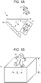
- Fig. 1A illustrates a schematic cross section of a display device using conventional retroreflection.
- the display device 10 includes a display 20 that outputs an image, a beam splitter 30, and a retroreflective member 40.
- the light emitted from the display 20 is reflected by the beam splitter 30, and the reflected light travels to the retroreflective member 40.
- the retroreflective member 40 reflects light in the same direction as incident light, and the reflected light passes through the beam splitter 30, and an aerial image 50 is displayed in a space in front of the observer's eyes.
- Such display of the aerial image 50 is known as an Aerial Imaging by Retro-Reflection (AIRR) method.
- Aerial Imaging by Retro-Reflection Aerial Imaging by Retro-Reflection
- Fig. 1B is a schematic external view of the display device using the AIRR method.
- the display device 10 includes, for example, a rectangular parallelepiped housing 60 as illustrated in the drawing, the beam splitter 30 is disposed on the surface of the housing 60, and the display 20 and the retroreflective member 40 are disposed inside the housing 60. Since the housing 60 requires an internal space for the display 20 and the retroreflective member 40 to be inclined, the thickness T of the housing 60 increases.
- the aerial image 50 that can be observed by the observer is limited to a range in which the observer can see the retroreflective member 40. That is, the retroreflective member 40 needs to be present within the viewing angle of the observer.
- the viewing angle ⁇ at which the aerial image 50 can be observed is about ⁇ 10 degrees to the left and right with respect to in front of the aerial image 50, and there is a problem in that the viewing angle is narrow.
- the aerial image 50 is formed at a position symmetrical to the display 20 with respect to the surface of the beam splitter 30.
- the aerial image 50 observed by the observer is not a video of the display 20 viewed from in front but a video viewed from an oblique direction of 45 degrees.
- An object of the present invention is to provide a display device capable of achieving thickness reduction, size reduction, and wide field of view, and enabling front viewing of a video of a light source, and a spatial input device using such display device.
- the invention relates to a display device and a spatial input device according to the appended claims. Embodiments are disclosed in the dependent claims.
- the display device further includes a polarizing member provided between the original video of the light guide plate and the polarization beam splitter, in which the polarizing member curbs transmission of light reflected by the original video through the polarization beam splitter.
- the polarizing member has a shape the same as or similar to a planar shape of the original video.
- the original video is formed on a bottom portion of the light guide plate, and the original video and an image in the air are at symmetrical positions with respect to a plane of the polarization beam splitter.
- the spatial input device includes a display device as described herein, and detection means configured to detect an approach of an object to a video in the air displayed by the display device.
- the detection means includes a capacitive sensor.
- the display device since the light is emitted from the side portion of the transparent light guide plate on which the original video of the aerial image is formed, and the video in the air of the original video is displayed by the retroreflection of the retroreflective member disposed below the light guide plate in parallel with the light guide plate, the display device can be downsized and thinned, and the observer can observe the video in the air of the original video viewed from the front at a wide viewing angle.
- the display device of the present invention displays a video using retroreflection in a three-dimensional space for which wearing special glasses or the like do not have to be worn.
- the display device of the present invention is applied to a user input interface using a video displayed in the air.
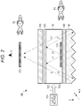
- FIG. 2 is a cross-sectional view illustrating a schematic configuration of a display device according to an example of the present invention.
- a display device 100 of the present example includes a light source 110, a light guide plate 120, a polarization beam splitter 130, a ⁇ /4 plate 140, a retroreflective member 150, and a transparent protective member 160. These members are accommodated in, for example, a rectangular parallelepiped housing, a housing, or the like.
- the light source 110 emits light L having a constant emission angle (or oblique angle) in the X-direction.
- the emitted light L enters the inside from a side portion 122 of the transparent light guide plate 120, and uniformly irradiates the inside of the light guide plate 120.
- the light source 110 is not particularly limited, but for example, a light emitting diode, a laser diode, or the like may be used. If the side portion 122 of the light guide plate 120 has a certain length in the Y-direction, the plurality of light sources 110 may be arranged along the Y-direction of the side portion 122 of the light guide plate 120. Here, light is incident from one side portion of the light guide plate 120, but the light may be incident from a plurality of side portions.
- the light guide plate 120 is a transparent plate-like optical member including a flat upper surface, a flat lower surface, and side surfaces connecting the upper surface and the lower surface.
- a known plate can be used as the light guide plate 120, and may be, for example, an acrylic plastic plate, or a plate made of a polycarbonate resin, a cycloolefin-based resin, or the like.
- the light guide plate 120 has a constant thickness in the Z-direction in order to allow light L of the light source 110 to enter from the side portion 122.
- a diffusion pattern for diffusing the incident light may be formed on the bottom portion or a bottom surface 124 of the light guide plate 120.
- a dot pattern may be formed by laser processing or printing. In this way, the light L incident from the side portion 122 of the light guide plate 120 is diffused or scattered by the diffusion pattern of the bottom portion 124 of the light guide plate 120, and the light guide plate 120 functions as if it were a surface light source.
- a light guide plate image 126 is further formed on the bottom portion or the bottom surface 124 of the light guide plate 120 as an original video P1 of the aerial image.
- a method of forming the light guide plate image 126 is not particularly limited, but for example, a two-dimensional image such as a groove or unevenness may be formed on the bottom portion 124 by laser processing, embossing, printing processing, or the like.
- the light L is incident from the side portion of the light guide plate 120, the light L is reflected by the light guide plate image 126, and the two-dimensional original video P1 is generated.
- the degree of diffusion or scattering of the bottom portion 124 in the region other than the light guide plate image 126 may be reduced.
- the polarization beam splitter 130 is disposed on the upper portion of the light guide plate 120 in parallel with the light guide plate 120.
- the polarization beam splitter 130 is a polarization separation element capable of dividing incident light into a p-polarization component and an s-polarization component, and can transmit a light component linearly polarized in a certain specific direction. If the light L incident from the light source 110 is non-polarized light including various polarized components, a part of light L1 reflected by the bottom portion 124 of the light guide plate 120 or the light guide plate image 126 passes through the polarization beam splitter 130, and most of the other light L2 is reflected by the polarization beam splitter 130.
- the direction of the linearly polarized light transmitted by the polarization beam splitter 130 is set to be different from the direction of the linearly polarized light of the incident light L, and most of the light L1 is reflected by the polarization beam splitter 130.
- the ⁇ /4 plate 140 is disposed below and parallel to the light guide plate 120.
- the light L2 emitted from the light guide plate 120 is incident on the ⁇ /4 plate 140, and a phase difference ⁇ /2 (90 degrees) is given to the incident light L2 to allow transmission of the incident light L2.
- a phase difference ⁇ /2 90 degrees
- linearly polarized light when linearly polarized light is incident, it is converted into circularly polarized light (or elliptically polarized light), and when circularly polarized light (or elliptically polarized light) is incident, it is converted into linearly polarized light.
- the retroreflective member 150 is disposed below and parallel to the ⁇ /4 plate 140.
- the retroreflective member 150 reflects the light L2 transmitted through the ⁇ /4 plate 140 and the light L3 in the same direction as the incident light.
- the structure and material of the retroreflective member 150 are not particularly limited as long as the retroreflective member can reflect light in the same direction as the incident direction.
- the retroreflective member 150 includes, for example, prismatic retroreflective elements such as triangular pyramid retroreflective elements and full cube corner retroreflective elements, or bead retroreflective elements.
- the light L3 reflected by the retroreflective member 150 is transmitted through the ⁇ /4 plate 140 again, a phase difference ⁇ /2 is given.
- the light L3 transmitted through the ⁇ /4 plate 140 has a phase difference ⁇ from the light L2 incident on the ⁇ /4 plate 140.
- the light incident on the ⁇ /4 plate 140 is linearly polarized light
- the light becomes circularly polarized light (or elliptically polarized light) when passing through the ⁇ /4 plate 140
- the circularly polarized light becomes circularly polarized light in the opposite direction
- this circularly polarized light in the opposite direction passes through the ⁇ /4 plate 140, it becomes linear polarized light in a direction 180 degrees different from the original linear polarized light.
- the light L3 transmitted through the ⁇ /4 plate 140 is incident on the polarization beam splitter 130, most of the light L3 is transmitted through the polarization beam splitter 130.
- a transparent protective member 160 is disposed above the polarization beam splitter 130.
- the transparent protective member 160 is made of, for example, a glass material or a plastic material.
- the transparent protective member 160 protects the surface of the polarization beam splitter 130, and the arrangement thereof is arbitrary.
- the light L3 transmitted through the transparent protective member 160 forms an image in the air, and the observer can observe the aerial image 170 immediately in front from a viewpoint U.
- the aerial image 170 is a video P2 in which an original video P1 of the light guide plate image 126 is floated upward as it is. That is, the aerial image 170 is displayed at a position symmetrical to the light guide plate image 126 with respect to the plane of the polarization beam splitter 130, and the observer can see the video P2 that is a front view of the original video P1.
- Fig. 3 is a schematic external perspective view of the display device of the present example.
- the transparent protective member 160 is disposed on the surface of the rectangular parallelepiped housing 180, and the light source 110, the light guide plate 120, the polarization beam splitter 130, the ⁇ /4 plate 140, and the retroreflective member 150 are accommodated therein. Since the retroreflective member 150 is disposed in parallel to the light guide plate 120, the polarization beam splitter 130, and the ⁇ /4 plate 140 without inclining the retroreflective member as in the conventional display device, a thickness Ta of the housing 180 in the Z-direction can be reduced.
- the light source 110 is disposed on the side portion of the light guide plate 120, this also contributes to thinning of the housing 180.
- the retroreflective member 150 is disposed horizontally in the X-direction, so that the viewing angle ⁇ a in the X-direction in which the aerial image 170 can be viewed can be increased.
- the viewing angle ⁇ a of the present example is at least twice the viewing angle ⁇ of the conventional display device 10 illustrated in Fig. 1 .
- the viewing angle in the Y-direction is also widened.
- the observer views both the original video P1 by the transmitted light and the video P2 of the aerial image 170 by the retroreflection in a double manner. Therefore, in the second example, the original video P1 of the light transmitted through the polarization beam splitter 130 is made invisible.
- Fig. 4 is a view illustrating a cross-sectional structure of a display device 100A according to a second example, and components the same as those in Fig. 2 are denoted by the same reference numerals.
- a polarizing member for example, a polarizing plate or a polarizing film
- the polarizing member 190 is disposed on the upper portion of the light guide plate 120 as illustrated in the drawing.
- the polarizing member 190 curbs transmission of the reflected light L1 of the light guide plate image 126 through the polarization beam splitter 130.
- the polarizing member 190 transmits light in a direction different from the direction of linearly polarized light transmitted by the polarization beam splitter 130.
- the polarizing member 190 for curbing transmission of the reflected light L1 of the light guide plate image 126 through the polarization beam splitter 130 is provided between the light guide plate image 126 and the polarization beam splitter 130, the observer cannot see the original video PI, and the contrast and visibility of the aerial image 170 can be improved.
- a third example relates to a spatial input device in which the display device of the first or second example is applied to a user input interface.
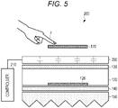
- Fig. 5 is a diagram illustrating a schematic configuration of a spatial input device according to the third example.
- the spatial input device 200 includes a sensor 200 that detects an object (for example, a user's finger or the like) on the aerial image 170 and a controller 210 that receives a detection result from the sensor 200 and performs various controls.
- an object for example, a user's finger or the like
- the sensor 200 is not particularly limited as long as it can transmit the aerial image 170, but for example, a non-contact capacitive sensor can be used.
- the transparent protective member 160 illustrated in Fig. 2 may be replaced with a capacitive sensor.
- the capacitive sensor detects a change in capacitance in a region where a conductor such as a user's finger approaches, like a capacitive touch panel.
- the capacitive sensor 200 detects the approach of the finger to the aerial image 170 and outputs the detection result to the controller 210.
- the user can perform input in a non-contact manner. For example, a clean and hygienic input can be realized as compared with an input button touched by an unspecified person.
- the spatial input device 200 of the present example can be applied to any user input, and can be applied to, for example, a computer device, an in-vehicle electronic device, an ATM of a bank or the like, a ticket purchasing machine of a station or the like, an input button of an elevator, and the like.
Landscapes
- Physics & Mathematics (AREA)
- General Physics & Mathematics (AREA)
- Optics & Photonics (AREA)
- Engineering & Computer Science (AREA)
- General Engineering & Computer Science (AREA)
- Theoretical Computer Science (AREA)
- Human Computer Interaction (AREA)
- Devices For Indicating Variable Information By Combining Individual Elements (AREA)
Abstract
Description
- The present invention relates to a display device, and particularly to a display device that displays an image in the air using retroreflection.
- An aerial display that forms an image displayed on a display in the air using a retroreflective member or the like has been proposed. For example, in order to enable observation of an image formed in the air from a wider angle, the display device of
JP 2017-107165 A JP 2018-81138 A JP 2019-66833 A JP 2019-101055 A -
Fig. 1A illustrates a schematic cross section of a display device using conventional retroreflection. As illustrated in the drawing, thedisplay device 10 includes adisplay 20 that outputs an image, abeam splitter 30, and aretroreflective member 40. The light emitted from thedisplay 20 is reflected by thebeam splitter 30, and the reflected light travels to theretroreflective member 40. Theretroreflective member 40 reflects light in the same direction as incident light, and the reflected light passes through thebeam splitter 30, and anaerial image 50 is displayed in a space in front of the observer's eyes. Such display of theaerial image 50 is known as an Aerial Imaging by Retro-Reflection (AIRR) method. -
Fig. 1B is a schematic external view of the display device using the AIRR method. Thedisplay device 10 includes, for example, a rectangularparallelepiped housing 60 as illustrated in the drawing, thebeam splitter 30 is disposed on the surface of thehousing 60, and thedisplay 20 and theretroreflective member 40 are disposed inside thehousing 60. Since thehousing 60 requires an internal space for thedisplay 20 and theretroreflective member 40 to be inclined, the thickness T of thehousing 60 increases. - In addition, the
aerial image 50 that can be observed by the observer is limited to a range in which the observer can see theretroreflective member 40. That is, theretroreflective member 40 needs to be present within the viewing angle of the observer. WhenFig. 1B is taken as an example, the viewing angle θ at which theaerial image 50 can be observed is about ±10 degrees to the left and right with respect to in front of theaerial image 50, and there is a problem in that the viewing angle is narrow. - Further, the
aerial image 50 is formed at a position symmetrical to thedisplay 20 with respect to the surface of thebeam splitter 30. In a case where thedisplay 20 is inclined at approximately 45 degrees with respect to thebeam splitter 30, theaerial image 50 observed by the observer is not a video of thedisplay 20 viewed from in front but a video viewed from an oblique direction of 45 degrees. - An object of the present invention is to provide a display device capable of achieving thickness reduction, size reduction, and wide field of view, and enabling front viewing of a video of a light source, and a spatial input device using such display device.
- The invention relates to a display device and a spatial input device according to the appended claims. Embodiments are disclosed in the dependent claims.
- The display device according to an aspect of the present invention capable of displaying a video in the air using retroreflection includes a transparent light guide plate including an original video of the video in the air, a light source configured to emit light from a side portion of the light guide plate toward the inside of the light guide plate, a polarization beam splitter disposed parallel to the light guide plate and above the light guide plate, a λ/4 plate disposed below the light guide plate, and a retroreflective member disposed parallel to the light guide plate and below the λ/4 plate, and retroreflects the original video to display the video in the air.
- In one aspect, the display device further includes a polarizing member provided between the original video of the light guide plate and the polarization beam splitter, in which the polarizing member curbs transmission of light reflected by the original video through the polarization beam splitter. In one aspect, the polarizing member has a shape the same as or similar to a planar shape of the original video. In one aspect, the original video is formed on a bottom portion of the light guide plate, and the original video and an image in the air are at symmetrical positions with respect to a plane of the polarization beam splitter.
- The spatial input device according to an aspect of the present invention includes a display device as described herein, and detection means configured to detect an approach of an object to a video in the air displayed by the display device. In one aspect, the detection means includes a capacitive sensor.
- According to aspects of the present invention, since the light is emitted from the side portion of the transparent light guide plate on which the original video of the aerial image is formed, and the video in the air of the original video is displayed by the retroreflection of the retroreflective member disposed below the light guide plate in parallel with the light guide plate, the display device can be downsized and thinned, and the observer can observe the video in the air of the original video viewed from the front at a wide viewing angle.
-
Fig. 1A is a schematic cross-sectional view of a conventional AIRR type display device, andFig. 1B is a schematic external view of the conventional display device. -
Fig. 2 is a diagram illustrating a schematic cross section of a display device according to a first example of the present invention. -
Fig. 3 is a schematic external view of the display device according to the first example of the present invention. -
Fig. 4 is a diagram illustrating a schematic cross section of a display device according to a second example of the present invention. -
Fig. 5 is a diagram illustrating a schematic configuration of a spatial input device according to a third example of the present invention. - Next, embodiments of the present invention will be described. The display device of the present invention displays a video using retroreflection in a three-dimensional space for which wearing special glasses or the like do not have to be worn. In an aspect, the display device of the present invention is applied to a user input interface using a video displayed in the air. It should be noted that the drawings referred to in the following description of the examples include exaggerated display in order to facilitate understanding of the invention, and do not directly represent the shape and scale of an actual product.
- Next, an example of the present invention will be described in detail.
Fig. 2 is a cross-sectional view illustrating a schematic configuration of a display device according to an example of the present invention. Adisplay device 100 of the present example includes alight source 110, alight guide plate 120, apolarization beam splitter 130, a λ/4plate 140, aretroreflective member 150, and a transparentprotective member 160. These members are accommodated in, for example, a rectangular parallelepiped housing, a housing, or the like. - The
light source 110 emits light L having a constant emission angle (or oblique angle) in the X-direction. The emitted light L enters the inside from aside portion 122 of the transparentlight guide plate 120, and uniformly irradiates the inside of thelight guide plate 120. Thelight source 110 is not particularly limited, but for example, a light emitting diode, a laser diode, or the like may be used. If theside portion 122 of thelight guide plate 120 has a certain length in the Y-direction, the plurality oflight sources 110 may be arranged along the Y-direction of theside portion 122 of thelight guide plate 120. Here, light is incident from one side portion of thelight guide plate 120, but the light may be incident from a plurality of side portions. - The
light guide plate 120 is a transparent plate-like optical member including a flat upper surface, a flat lower surface, and side surfaces connecting the upper surface and the lower surface. A known plate can be used as thelight guide plate 120, and may be, for example, an acrylic plastic plate, or a plate made of a polycarbonate resin, a cycloolefin-based resin, or the like. Thelight guide plate 120 has a constant thickness in the Z-direction in order to allow light L of thelight source 110 to enter from theside portion 122. A diffusion pattern for diffusing the incident light may be formed on the bottom portion or abottom surface 124 of thelight guide plate 120. For example, a dot pattern may be formed by laser processing or printing. In this way, the light L incident from theside portion 122 of thelight guide plate 120 is diffused or scattered by the diffusion pattern of thebottom portion 124 of thelight guide plate 120, and thelight guide plate 120 functions as if it were a surface light source. - A light
guide plate image 126 is further formed on the bottom portion or thebottom surface 124 of thelight guide plate 120 as an original video P1 of the aerial image. A method of forming the lightguide plate image 126 is not particularly limited, but for example, a two-dimensional image such as a groove or unevenness may be formed on thebottom portion 124 by laser processing, embossing, printing processing, or the like. When the light L is incident from the side portion of thelight guide plate 120, the light L is reflected by the lightguide plate image 126, and the two-dimensional original video P1 is generated. When it is desired to further increase the luminance of the lightguide plate image 126, the degree of diffusion or scattering of thebottom portion 124 in the region other than the lightguide plate image 126 may be reduced. - The
polarization beam splitter 130 is disposed on the upper portion of thelight guide plate 120 in parallel with thelight guide plate 120. Thepolarization beam splitter 130 is a polarization separation element capable of dividing incident light into a p-polarization component and an s-polarization component, and can transmit a light component linearly polarized in a certain specific direction. If the light L incident from thelight source 110 is non-polarized light including various polarized components, a part of light L1 reflected by thebottom portion 124 of thelight guide plate 120 or the lightguide plate image 126 passes through thepolarization beam splitter 130, and most of the other light L2 is reflected by thepolarization beam splitter 130. If the light L incident from thelight source 110 is linearly polarized light, the direction of the linearly polarized light transmitted by thepolarization beam splitter 130 is set to be different from the direction of the linearly polarized light of the incident light L, and most of the light L1 is reflected by thepolarization beam splitter 130. - The λ/4
plate 140 is disposed below and parallel to thelight guide plate 120. The light L2 emitted from thelight guide plate 120 is incident on the λ/4plate 140, and a phase difference π/2 (90 degrees) is given to the incident light L2 to allow transmission of the incident light L2. For example, when linearly polarized light is incident, it is converted into circularly polarized light (or elliptically polarized light), and when circularly polarized light (or elliptically polarized light) is incident, it is converted into linearly polarized light. - The
retroreflective member 150 is disposed below and parallel to the λ/4plate 140. Theretroreflective member 150 reflects the light L2 transmitted through the λ/4plate 140 and the light L3 in the same direction as the incident light. The structure and material of theretroreflective member 150 are not particularly limited as long as the retroreflective member can reflect light in the same direction as the incident direction. Theretroreflective member 150 includes, for example, prismatic retroreflective elements such as triangular pyramid retroreflective elements and full cube corner retroreflective elements, or bead retroreflective elements. - When the light L3 reflected by the
retroreflective member 150 is transmitted through the λ/4plate 140 again, a phase difference π/2 is given. Thus, the light L3 transmitted through the λ/4plate 140 has a phase difference π from the light L2 incident on the λ/4plate 140. For example, if the light incident on the λ/4plate 140 is linearly polarized light, the light becomes circularly polarized light (or elliptically polarized light) when passing through the λ/4plate 140, when the circularly polarized light is retroreflected an odd number of times by theretroreflective member 150, the circularly polarized light becomes circularly polarized light in the opposite direction, and when this circularly polarized light in the opposite direction passes through the λ/4plate 140, it becomes linear polarized light in adirection 180 degrees different from the original linear polarized light. Thus, when the light L3 transmitted through the λ/4plate 140 is incident on thepolarization beam splitter 130, most of the light L3 is transmitted through thepolarization beam splitter 130. - A transparent
protective member 160 is disposed above thepolarization beam splitter 130. The transparentprotective member 160 is made of, for example, a glass material or a plastic material. The transparentprotective member 160 protects the surface of thepolarization beam splitter 130, and the arrangement thereof is arbitrary. The light L3 transmitted through the transparentprotective member 160 forms an image in the air, and the observer can observe theaerial image 170 immediately in front from a viewpoint U. Theaerial image 170 is a video P2 in which an original video P1 of the lightguide plate image 126 is floated upward as it is. That is, theaerial image 170 is displayed at a position symmetrical to the lightguide plate image 126 with respect to the plane of thepolarization beam splitter 130, and the observer can see the video P2 that is a front view of the original video P1. -
Fig. 3 is a schematic external perspective view of the display device of the present example. In thedisplay device 100, for example, the transparentprotective member 160 is disposed on the surface of therectangular parallelepiped housing 180, and thelight source 110, thelight guide plate 120, thepolarization beam splitter 130, the λ/4plate 140, and theretroreflective member 150 are accommodated therein. Since theretroreflective member 150 is disposed in parallel to thelight guide plate 120, thepolarization beam splitter 130, and the λ/4plate 140 without inclining the retroreflective member as in the conventional display device, a thickness Ta of thehousing 180 in the Z-direction can be reduced. In addition, since thelight source 110 is disposed on the side portion of thelight guide plate 120, this also contributes to thinning of thehousing 180. Furthermore, since theretroreflective member 150 is disposed horizontally in the X-direction, the range in the X-direction in which theretroreflective member 150 can be observed from the viewpoint U of the observer is widened, so that the viewing angle θa in the X-direction in which theaerial image 170 can be viewed can be increased. The viewing angle θa of the present example is at least twice the viewing angle θ of theconventional display device 10 illustrated inFig. 1 . Similarly, since the range in the Y-direction in which theretroreflective member 150 can be viewed from the viewpoint U is also widened, the viewing angle in the Y-direction is also widened. - Next, a second example of the present invention will be described. In the first example, since a part of the component of the light L1 reflected by the light
guide plate image 126 is transmitted through thepolarization beam splitter 130, the observer views both the original video P1 by the transmitted light and the video P2 of theaerial image 170 by the retroreflection in a double manner. Therefore, in the second example, the original video P1 of the light transmitted through thepolarization beam splitter 130 is made invisible. -
Fig. 4 is a view illustrating a cross-sectional structure of adisplay device 100A according to a second example, and components the same as those inFig. 2 are denoted by the same reference numerals. In the second example, a polarizing member (for example, a polarizing plate or a polarizing film) 190 having the same or similar shape as the lightguide plate image 126 is disposed between the lightguide plate image 126 and thepolarization beam splitter 130. For example, the polarizingmember 190 is disposed on the upper portion of thelight guide plate 120 as illustrated in the drawing. Thepolarizing member 190 curbs transmission of the reflected light L1 of the lightguide plate image 126 through thepolarization beam splitter 130. For example, the polarizingmember 190 transmits light in a direction different from the direction of linearly polarized light transmitted by thepolarization beam splitter 130. - As described above, according to the present example, since the
polarizing member 190 for curbing transmission of the reflected light L1 of the lightguide plate image 126 through thepolarization beam splitter 130 is provided between the lightguide plate image 126 and thepolarization beam splitter 130, the observer cannot see the original video PI, and the contrast and visibility of theaerial image 170 can be improved. - Next, a third example of the present invention will be described. A third example relates to a spatial input device in which the display device of the first or second example is applied to a user input interface.
Fig. 5 is a diagram illustrating a schematic configuration of a spatial input device according to the third example. Thespatial input device 200 includes asensor 200 that detects an object (for example, a user's finger or the like) on theaerial image 170 and acontroller 210 that receives a detection result from thesensor 200 and performs various controls. - The
sensor 200 is not particularly limited as long as it can transmit theaerial image 170, but for example, a non-contact capacitive sensor can be used. In this case, the transparentprotective member 160 illustrated inFig. 2 may be replaced with a capacitive sensor. The capacitive sensor detects a change in capacitance in a region where a conductor such as a user's finger approaches, like a capacitive touch panel. As illustrated in the drawing, when the user holds the finger F over theaerial image 170, thecapacitive sensor 200 detects the approach of the finger to theaerial image 170 and outputs the detection result to thecontroller 210. As a result, the user can perform input in a non-contact manner. For example, a clean and hygienic input can be realized as compared with an input button touched by an unspecified person. - The
spatial input device 200 of the present example can be applied to any user input, and can be applied to, for example, a computer device, an in-vehicle electronic device, an ATM of a bank or the like, a ticket purchasing machine of a station or the like, an input button of an elevator, and the like. - Although the preferred embodiments of the present invention have been described in detail above, the present invention is not limited to the specific embodiments, and various modifications and changes can be made within the scope of the gist of the invention set forth in the claims.
-
- 100
- display device
- 110
- light source
- 120
- light guide plate
- 122
- side portion
- 124
- bottom portion
- 126
- light guide plate image
- 130
- polarization beam splitter
- 140
- λ/4 plate
- 150
- retroreflective member
- 160
- transparent protective member
- 170
- aerial image
- 180
- housing
- 190
- polarizing member
Claims (6)
- A display device (100) capable of displaying a video in the air using retroreflection, the display device (100) comprising:a transparent light guide plate (120) including an original video of the video in the air;a light source (110) configured to emit light from a side portion (122) of the light guide plate (120) toward the inside of the light guide plate (120);a polarization beam splitter (130) disposed parallel to the light guide plate (120) and above the light guide plate (120);a λ/4 plate (140) disposed below the light guide plate (120); anda retroreflective member (150) disposed in parallel with the light guide plate (120) and below the λ/4 plate (140),wherein the display device (100) retroreflects the original video to display the video in the air.
- The display device (100) according to claim 1 further comprising:a polarizing member (190) provided between the original video of the light guide plate (120) and the polarization beam splitter (130),wherein the polarizing member (190) suppresses transmission of light reflected by the original video through the polarization beam splitter (130).
- The display device (100) according to claim 2, wherein the polarizing member (190) has a shape the same as or similar to a planar shape of the original video.
- The display device (100) according to one of claims 1 to 3, wherein the original video is formed on a bottom portion (124) of the light guide plate (120), and the original video and an image in the air are at symmetrical positions with respect to a plane of the polarization beam splitter (130).
- A spatial input device (200) comprising:the display device (100) according to any one of claims 1 to 4; anddetection means configured to detect an approach of an object to a video in the air displayed by the display device (100).
- The spatial input device (200) according to claim 5, wherein the detection means includes a capacitive sensor (200).
Applications Claiming Priority (1)
| Application Number | Priority Date | Filing Date | Title |
|---|---|---|---|
| JP2021052706A JP7566428B2 (en) | 2021-03-26 | 2021-03-26 | Display device |
Publications (2)
| Publication Number | Publication Date |
|---|---|
| EP4071526A1 true EP4071526A1 (en) | 2022-10-12 |
| EP4071526B1 EP4071526B1 (en) | 2025-01-08 |
Family
ID=80820232
Family Applications (1)
| Application Number | Title | Priority Date | Filing Date |
|---|---|---|---|
| EP22162944.7A Active EP4071526B1 (en) | 2021-03-26 | 2022-03-18 | Display device |
Country Status (4)
| Country | Link |
|---|---|
| US (1) | US12313846B2 (en) |
| EP (1) | EP4071526B1 (en) |
| JP (1) | JP7566428B2 (en) |
| CN (1) | CN115128831A (en) |
Cited By (1)
| Publication number | Priority date | Publication date | Assignee | Title |
|---|---|---|---|---|
| US12493199B2 (en) * | 2021-10-08 | 2025-12-09 | Shanghai Yupei Photoelectric Technology Limited | Splicing display apparatus for floating image and multi-layer display device comprising the same |
Families Citing this family (3)
| Publication number | Priority date | Publication date | Assignee | Title |
|---|---|---|---|---|
| JP2024101393A (en) * | 2023-01-17 | 2024-07-29 | Toppanホールディングス株式会社 | Aerial display devices and display devices |
| JP2024111912A (en) | 2023-02-07 | 2024-08-20 | アルプスアルパイン株式会社 | Input display device |
| JP2026066525A (en) * | 2024-10-07 | 2026-04-17 | アルプスアルパイン株式会社 | Air input device |
Citations (7)
| Publication number | Priority date | Publication date | Assignee | Title |
|---|---|---|---|---|
| JP2017107165A (en) | 2015-12-07 | 2017-06-15 | 国立大学法人宇都宮大学 | Display device and display method of aerial image |
| WO2017098718A1 (en) * | 2015-12-07 | 2017-06-15 | 富士フイルム株式会社 | Backlight unit |
| JP2018081138A (en) | 2016-11-14 | 2018-05-24 | 日本カーバイド工業株式会社 | Image display unit |
| WO2018151220A1 (en) * | 2017-02-15 | 2018-08-23 | 富士フイルム株式会社 | Optical device |
| JP2019066833A (en) | 2017-09-29 | 2019-04-25 | 日本カーバイド工業株式会社 | Image display device |
| JP2019101055A (en) | 2017-11-28 | 2019-06-24 | コニカミノルタ株式会社 | Aerial video display device |
| CN212675516U (en) * | 2020-08-18 | 2021-03-09 | 安徽省东超科技有限公司 | Non-contact control type thermal power plant and host thereof |
Family Cites Families (10)
| Publication number | Priority date | Publication date | Assignee | Title |
|---|---|---|---|---|
| GB2284680A (en) * | 1993-12-13 | 1995-06-14 | Central Research Lab Ltd | Apparatus for displaying a suspended image |
| WO2017099116A1 (en) | 2015-12-07 | 2017-06-15 | 国立大学法人宇都宮大学 | Display device, and display method for aerial image |
| TW201732373A (en) * | 2016-02-24 | 2017-09-16 | Omron Tateisi Electronics Co | Display device |
| EP3508909A1 (en) | 2016-08-31 | 2019-07-10 | Scivax Corporation | Optical imaging apparatus |
| JP6778916B2 (en) * | 2016-11-17 | 2020-11-04 | パナソニックIpマネジメント株式会社 | Display device |
| US10151931B2 (en) | 2017-01-05 | 2018-12-11 | Looking Glass Factory, Inc. | Advanced retroreflecting aerial displays |
| CN108319018A (en) * | 2018-02-12 | 2018-07-24 | 杭州太若科技有限公司 | A kind of augmented reality device, equipment and the method for realizing augmented reality |
| JP7056423B2 (en) * | 2018-07-10 | 2022-04-19 | オムロン株式会社 | Input device |
| JP2022139533A (en) | 2021-03-12 | 2022-09-26 | ミネベアミツミ株式会社 | Aerial display device |
| JP7706832B2 (en) * | 2021-05-18 | 2025-07-14 | アルプスアルパイン株式会社 | Input Devices |
-
2021
- 2021-03-26 JP JP2021052706A patent/JP7566428B2/en active Active
-
2022
- 2022-03-18 EP EP22162944.7A patent/EP4071526B1/en active Active
- 2022-03-24 CN CN202210297539.2A patent/CN115128831A/en active Pending
- 2022-03-24 US US17/703,033 patent/US12313846B2/en active Active
Patent Citations (7)
| Publication number | Priority date | Publication date | Assignee | Title |
|---|---|---|---|---|
| JP2017107165A (en) | 2015-12-07 | 2017-06-15 | 国立大学法人宇都宮大学 | Display device and display method of aerial image |
| WO2017098718A1 (en) * | 2015-12-07 | 2017-06-15 | 富士フイルム株式会社 | Backlight unit |
| JP2018081138A (en) | 2016-11-14 | 2018-05-24 | 日本カーバイド工業株式会社 | Image display unit |
| WO2018151220A1 (en) * | 2017-02-15 | 2018-08-23 | 富士フイルム株式会社 | Optical device |
| JP2019066833A (en) | 2017-09-29 | 2019-04-25 | 日本カーバイド工業株式会社 | Image display device |
| JP2019101055A (en) | 2017-11-28 | 2019-06-24 | コニカミノルタ株式会社 | Aerial video display device |
| CN212675516U (en) * | 2020-08-18 | 2021-03-09 | 安徽省东超科技有限公司 | Non-contact control type thermal power plant and host thereof |
Cited By (1)
| Publication number | Priority date | Publication date | Assignee | Title |
|---|---|---|---|---|
| US12493199B2 (en) * | 2021-10-08 | 2025-12-09 | Shanghai Yupei Photoelectric Technology Limited | Splicing display apparatus for floating image and multi-layer display device comprising the same |
Also Published As
| Publication number | Publication date |
|---|---|
| CN115128831A (en) | 2022-09-30 |
| JP2022150214A (en) | 2022-10-07 |
| EP4071526B1 (en) | 2025-01-08 |
| JP7566428B2 (en) | 2024-10-15 |
| US12313846B2 (en) | 2025-05-27 |
| US20220308348A1 (en) | 2022-09-29 |
Similar Documents
| Publication | Publication Date | Title |
|---|---|---|
| EP4071526B1 (en) | Display device | |
| EP4095589B1 (en) | Display device | |
| EP4071525A1 (en) | Display device | |
| CN107077003B (en) | Optical device | |
| EP0734541B1 (en) | Apparatus for displaying an image | |
| US20100026723A1 (en) | Image magnification system for computer interface | |
| EP4134730B1 (en) | Display device and spatial input device including the same | |
| GB2470737A (en) | A display panel for 3D position sensing of a light reflecting/emitting object | |
| WO2019163339A1 (en) | Non-contact input device and non-contact input method | |
| CN117837138A (en) | Space suspended image information display system and stereoscopic sensing device used therein | |
| US20240427168A1 (en) | Display device | |
| EP4485048A1 (en) | Display device | |
| US20130135452A1 (en) | Image display apparatus | |
| EP4560366A1 (en) | Display device | |
| US20250164819A1 (en) | Display device | |
| EP4726442A1 (en) | Display apparatus | |
| WO2025142214A1 (en) | Input device | |
| JP2025033989A (en) | Vehicle display device | |
| TW202507379A (en) | Image display device | |
| CN119301510A (en) | Space suspended image display device | |
| KR20250114907A (en) | Display device | |
| KR20250015971A (en) | Display device | |
| CN118131500A (en) | Aerial floating image display device | |
| JP2023001954A (en) | Aerial video display device | |
| JP2020183986A (en) | Display device |
Legal Events
| Date | Code | Title | Description |
|---|---|---|---|
| PUAI | Public reference made under article 153(3) epc to a published international application that has entered the european phase |
Free format text: ORIGINAL CODE: 0009012 |
|
| STAA | Information on the status of an ep patent application or granted ep patent |
Free format text: STATUS: THE APPLICATION HAS BEEN PUBLISHED |
|
| AK | Designated contracting states |
Kind code of ref document: A1 Designated state(s): AL AT BE BG CH CY CZ DE DK EE ES FI FR GB GR HR HU IE IS IT LI LT LU LV MC MK MT NL NO PL PT RO RS SE SI SK SM TR |
|
| STAA | Information on the status of an ep patent application or granted ep patent |
Free format text: STATUS: REQUEST FOR EXAMINATION WAS MADE |
|
| 17P | Request for examination filed |
Effective date: 20230330 |
|
| RBV | Designated contracting states (corrected) |
Designated state(s): AL AT BE BG CH CY CZ DE DK EE ES FI FR GB GR HR HU IE IS IT LI LT LU LV MC MK MT NL NO PL PT RO RS SE SI SK SM TR |
|
| GRAP | Despatch of communication of intention to grant a patent |
Free format text: ORIGINAL CODE: EPIDOSNIGR1 |
|
| STAA | Information on the status of an ep patent application or granted ep patent |
Free format text: STATUS: GRANT OF PATENT IS INTENDED |
|
| RIC1 | Information provided on ipc code assigned before grant |
Ipc: G02B 30/40 20200101ALI20240808BHEP Ipc: G02B 30/60 20200101ALI20240808BHEP Ipc: G03B 21/00 20060101ALI20240808BHEP Ipc: G02B 5/124 20060101AFI20240808BHEP |
|
| INTG | Intention to grant announced |
Effective date: 20240906 |
|
| GRAS | Grant fee paid |
Free format text: ORIGINAL CODE: EPIDOSNIGR3 |
|
| GRAA | (expected) grant |
Free format text: ORIGINAL CODE: 0009210 |
|
| STAA | Information on the status of an ep patent application or granted ep patent |
Free format text: STATUS: THE PATENT HAS BEEN GRANTED |
|
| AK | Designated contracting states |
Kind code of ref document: B1 Designated state(s): AL AT BE BG CH CY CZ DE DK EE ES FI FR GB GR HR HU IE IS IT LI LT LU LV MC MK MT NL NO PL PT RO RS SE SI SK SM TR |
|
| P01 | Opt-out of the competence of the unified patent court (upc) registered |
Free format text: CASE NUMBER: APP_64017/2024 Effective date: 20241203 |
|
| REG | Reference to a national code |
Ref country code: GB Ref legal event code: FG4D |
|
| REG | Reference to a national code |
Ref country code: CH Ref legal event code: EP |
|
| REG | Reference to a national code |
Ref country code: DE Ref legal event code: R096 Ref document number: 602022009469 Country of ref document: DE |
|
| REG | Reference to a national code |
Ref country code: IE Ref legal event code: FG4D |
|
| PGFP | Annual fee paid to national office [announced via postgrant information from national office to epo] |
Ref country code: AT Payment date: 20250417 Year of fee payment: 4 |
|
| REG | Reference to a national code |
Ref country code: LT Ref legal event code: MG9D |
|
| REG | Reference to a national code |
Ref country code: NL Ref legal event code: MP Effective date: 20250108 |
|
| REG | Reference to a national code |
Ref country code: AT Ref legal event code: MK05 Ref document number: 1758688 Country of ref document: AT Kind code of ref document: T Effective date: 20250108 |
|
| PG25 | Lapsed in a contracting state [announced via postgrant information from national office to epo] |
Ref country code: NL Free format text: LAPSE BECAUSE OF FAILURE TO SUBMIT A TRANSLATION OF THE DESCRIPTION OR TO PAY THE FEE WITHIN THE PRESCRIBED TIME-LIMIT Effective date: 20250108 |
|
| PG25 | Lapsed in a contracting state [announced via postgrant information from national office to epo] |
Ref country code: RS Free format text: LAPSE BECAUSE OF FAILURE TO SUBMIT A TRANSLATION OF THE DESCRIPTION OR TO PAY THE FEE WITHIN THE PRESCRIBED TIME-LIMIT Effective date: 20250408 |
|
| PG25 | Lapsed in a contracting state [announced via postgrant information from national office to epo] |
Ref country code: PL Free format text: LAPSE BECAUSE OF FAILURE TO SUBMIT A TRANSLATION OF THE DESCRIPTION OR TO PAY THE FEE WITHIN THE PRESCRIBED TIME-LIMIT Effective date: 20250108 |
|
| PG25 | Lapsed in a contracting state [announced via postgrant information from national office to epo] |
Ref country code: ES Free format text: LAPSE BECAUSE OF FAILURE TO SUBMIT A TRANSLATION OF THE DESCRIPTION OR TO PAY THE FEE WITHIN THE PRESCRIBED TIME-LIMIT Effective date: 20250108 |
|
| PG25 | Lapsed in a contracting state [announced via postgrant information from national office to epo] |
Ref country code: NO Free format text: LAPSE BECAUSE OF FAILURE TO SUBMIT A TRANSLATION OF THE DESCRIPTION OR TO PAY THE FEE WITHIN THE PRESCRIBED TIME-LIMIT Effective date: 20250408 Ref country code: IS Free format text: LAPSE BECAUSE OF FAILURE TO SUBMIT A TRANSLATION OF THE DESCRIPTION OR TO PAY THE FEE WITHIN THE PRESCRIBED TIME-LIMIT Effective date: 20250508 |
|
| PG25 | Lapsed in a contracting state [announced via postgrant information from national office to epo] |
Ref country code: HR Free format text: LAPSE BECAUSE OF FAILURE TO SUBMIT A TRANSLATION OF THE DESCRIPTION OR TO PAY THE FEE WITHIN THE PRESCRIBED TIME-LIMIT Effective date: 20250108 |
|
| PG25 | Lapsed in a contracting state [announced via postgrant information from national office to epo] |
Ref country code: LV Free format text: LAPSE BECAUSE OF FAILURE TO SUBMIT A TRANSLATION OF THE DESCRIPTION OR TO PAY THE FEE WITHIN THE PRESCRIBED TIME-LIMIT Effective date: 20250108 Ref country code: PT Free format text: LAPSE BECAUSE OF FAILURE TO SUBMIT A TRANSLATION OF THE DESCRIPTION OR TO PAY THE FEE WITHIN THE PRESCRIBED TIME-LIMIT Effective date: 20250508 |
|
| PG25 | Lapsed in a contracting state [announced via postgrant information from national office to epo] |
Ref country code: BG Free format text: LAPSE BECAUSE OF FAILURE TO SUBMIT A TRANSLATION OF THE DESCRIPTION OR TO PAY THE FEE WITHIN THE PRESCRIBED TIME-LIMIT Effective date: 20250108 Ref country code: GR Free format text: LAPSE BECAUSE OF FAILURE TO SUBMIT A TRANSLATION OF THE DESCRIPTION OR TO PAY THE FEE WITHIN THE PRESCRIBED TIME-LIMIT Effective date: 20250409 |
|
| PG25 | Lapsed in a contracting state [announced via postgrant information from national office to epo] |
Ref country code: AT Free format text: LAPSE BECAUSE OF FAILURE TO SUBMIT A TRANSLATION OF THE DESCRIPTION OR TO PAY THE FEE WITHIN THE PRESCRIBED TIME-LIMIT Effective date: 20250108 |
|
| PG25 | Lapsed in a contracting state [announced via postgrant information from national office to epo] |
Ref country code: SE Free format text: LAPSE BECAUSE OF FAILURE TO SUBMIT A TRANSLATION OF THE DESCRIPTION OR TO PAY THE FEE WITHIN THE PRESCRIBED TIME-LIMIT Effective date: 20250108 |
|
| PG25 | Lapsed in a contracting state [announced via postgrant information from national office to epo] |
Ref country code: SM Free format text: LAPSE BECAUSE OF FAILURE TO SUBMIT A TRANSLATION OF THE DESCRIPTION OR TO PAY THE FEE WITHIN THE PRESCRIBED TIME-LIMIT Effective date: 20250108 |
|
| REG | Reference to a national code |
Ref country code: DE Ref legal event code: R097 Ref document number: 602022009469 Country of ref document: DE |
|
| PG25 | Lapsed in a contracting state [announced via postgrant information from national office to epo] |
Ref country code: DK Free format text: LAPSE BECAUSE OF FAILURE TO SUBMIT A TRANSLATION OF THE DESCRIPTION OR TO PAY THE FEE WITHIN THE PRESCRIBED TIME-LIMIT Effective date: 20250108 |
|
| PG25 | Lapsed in a contracting state [announced via postgrant information from national office to epo] |
Ref country code: MC Free format text: LAPSE BECAUSE OF FAILURE TO SUBMIT A TRANSLATION OF THE DESCRIPTION OR TO PAY THE FEE WITHIN THE PRESCRIBED TIME-LIMIT Effective date: 20250108 |
|
| PG25 | Lapsed in a contracting state [announced via postgrant information from national office to epo] |
Ref country code: EE Free format text: LAPSE BECAUSE OF FAILURE TO SUBMIT A TRANSLATION OF THE DESCRIPTION OR TO PAY THE FEE WITHIN THE PRESCRIBED TIME-LIMIT Effective date: 20250108 Ref country code: CZ Free format text: LAPSE BECAUSE OF FAILURE TO SUBMIT A TRANSLATION OF THE DESCRIPTION OR TO PAY THE FEE WITHIN THE PRESCRIBED TIME-LIMIT Effective date: 20250108 |
|
| REG | Reference to a national code |
Ref country code: CH Ref legal event code: H13 Free format text: ST27 STATUS EVENT CODE: U-0-0-H10-H13 (AS PROVIDED BY THE NATIONAL OFFICE) Effective date: 20251023 |
|
| PG25 | Lapsed in a contracting state [announced via postgrant information from national office to epo] |
Ref country code: RO Free format text: LAPSE BECAUSE OF FAILURE TO SUBMIT A TRANSLATION OF THE DESCRIPTION OR TO PAY THE FEE WITHIN THE PRESCRIBED TIME-LIMIT Effective date: 20250108 |
|
| PG25 | Lapsed in a contracting state [announced via postgrant information from national office to epo] |
Ref country code: SK Free format text: LAPSE BECAUSE OF FAILURE TO SUBMIT A TRANSLATION OF THE DESCRIPTION OR TO PAY THE FEE WITHIN THE PRESCRIBED TIME-LIMIT Effective date: 20250108 |
|
| PLBE | No opposition filed within time limit |
Free format text: ORIGINAL CODE: 0009261 |
|
| STAA | Information on the status of an ep patent application or granted ep patent |
Free format text: STATUS: NO OPPOSITION FILED WITHIN TIME LIMIT |
|
| PG25 | Lapsed in a contracting state [announced via postgrant information from national office to epo] |
Ref country code: LU Free format text: LAPSE BECAUSE OF NON-PAYMENT OF DUE FEES Effective date: 20250318 |
|
| REG | Reference to a national code |
Ref country code: BE Ref legal event code: MM Effective date: 20250331 |
|
| 26N | No opposition filed |
Effective date: 20251009 |
|
| PG25 | Lapsed in a contracting state [announced via postgrant information from national office to epo] |
Ref country code: BE Free format text: LAPSE BECAUSE OF NON-PAYMENT OF DUE FEES Effective date: 20250331 |
|
| PG25 | Lapsed in a contracting state [announced via postgrant information from national office to epo] |
Ref country code: CH Free format text: LAPSE BECAUSE OF NON-PAYMENT OF DUE FEES Effective date: 20250331 |
|
| PG25 | Lapsed in a contracting state [announced via postgrant information from national office to epo] |
Ref country code: IE Free format text: LAPSE BECAUSE OF NON-PAYMENT OF DUE FEES Effective date: 20250318 |
|
| PG25 | Lapsed in a contracting state [announced via postgrant information from national office to epo] |
Ref country code: IT Free format text: LAPSE BECAUSE OF FAILURE TO SUBMIT A TRANSLATION OF THE DESCRIPTION OR TO PAY THE FEE WITHIN THE PRESCRIBED TIME-LIMIT Effective date: 20250108 |
|
| PGFP | Annual fee paid to national office [announced via postgrant information from national office to epo] |
Ref country code: GB Payment date: 20260324 Year of fee payment: 5 |
|
| PGFP | Annual fee paid to national office [announced via postgrant information from national office to epo] |
Ref country code: DE Payment date: 20260319 Year of fee payment: 5 |
|
| PGFP | Annual fee paid to national office [announced via postgrant information from national office to epo] |
Ref country code: FR Payment date: 20260323 Year of fee payment: 5 |