EP4071329B1 - Einstellbare stopperanordnung für ein fahrzeug - Google Patents
Einstellbare stopperanordnung für ein fahrzeug Download PDFInfo
- Publication number
- EP4071329B1 EP4071329B1 EP22165487.4A EP22165487A EP4071329B1 EP 4071329 B1 EP4071329 B1 EP 4071329B1 EP 22165487 A EP22165487 A EP 22165487A EP 4071329 B1 EP4071329 B1 EP 4071329B1
- Authority
- EP
- European Patent Office
- Prior art keywords
- resiliently deformable
- shank
- stopper assembly
- adjustable stopper
- assembly according
- Prior art date
- Legal status (The legal status is an assumption and is not a legal conclusion. Google has not performed a legal analysis and makes no representation as to the accuracy of the status listed.)
- Active
Links
Images




Classifications
-
- E—FIXED CONSTRUCTIONS
- E05—LOCKS; KEYS; WINDOW OR DOOR FITTINGS; SAFES
- E05D—HINGES OR SUSPENSION DEVICES FOR DOORS, WINDOWS OR WINGS
- E05D11/00—Additional features or accessories of hinges
- E05D11/10—Devices for preventing movement between relatively-movable hinge parts
- E05D11/1028—Devices for preventing movement between relatively-movable hinge parts for maintaining the hinge in two or more positions, e.g. intermediate or fully open
- E05D11/105—Devices for preventing movement between relatively-movable hinge parts for maintaining the hinge in two or more positions, e.g. intermediate or fully open the maintaining means acting perpendicularly to the pivot axis
- E05D11/1057—Devices for preventing movement between relatively-movable hinge parts for maintaining the hinge in two or more positions, e.g. intermediate or fully open the maintaining means acting perpendicularly to the pivot axis specially adapted for vehicles
-
- E—FIXED CONSTRUCTIONS
- E05—LOCKS; KEYS; WINDOW OR DOOR FITTINGS; SAFES
- E05F—DEVICES FOR MOVING WINGS INTO OPEN OR CLOSED POSITION; CHECKS FOR WINGS; WING FITTINGS NOT OTHERWISE PROVIDED FOR, CONCERNED WITH THE FUNCTIONING OF THE WING
- E05F5/00—Braking devices, e.g. checks; Stops; Buffers
- E05F5/02—Braking devices, e.g. checks; Stops; Buffers specially for preventing the slamming of swinging wings during final closing movement, e.g. jamb stops
- E05F5/022—Braking devices, e.g. checks; Stops; Buffers specially for preventing the slamming of swinging wings during final closing movement, e.g. jamb stops specially adapted for vehicles, e.g. for hoods or trunks
-
- E—FIXED CONSTRUCTIONS
- E05—LOCKS; KEYS; WINDOW OR DOOR FITTINGS; SAFES
- E05D—HINGES OR SUSPENSION DEVICES FOR DOORS, WINDOWS OR WINGS
- E05D11/00—Additional features or accessories of hinges
-
- E—FIXED CONSTRUCTIONS
- E05—LOCKS; KEYS; WINDOW OR DOOR FITTINGS; SAFES
- E05D—HINGES OR SUSPENSION DEVICES FOR DOORS, WINDOWS OR WINGS
- E05D7/00—Hinges or pivots of special construction
-
- E—FIXED CONSTRUCTIONS
- E05—LOCKS; KEYS; WINDOW OR DOOR FITTINGS; SAFES
- E05Y—INDEXING SCHEME ASSOCIATED WITH SUBCLASSES E05D AND E05F, RELATING TO CONSTRUCTION ELEMENTS, ELECTRIC CONTROL, POWER SUPPLY, POWER SIGNAL OR TRANSMISSION, USER INTERFACES, MOUNTING OR COUPLING, DETAILS, ACCESSORIES, AUXILIARY OPERATIONS NOT OTHERWISE PROVIDED FOR, APPLICATION THEREOF
- E05Y2600/00—Mounting or coupling arrangements for elements provided for in this subclass
- E05Y2600/10—Adjustable
- E05Y2600/12—Adjustable by manual operation
-
- E—FIXED CONSTRUCTIONS
- E05—LOCKS; KEYS; WINDOW OR DOOR FITTINGS; SAFES
- E05Y—INDEXING SCHEME ASSOCIATED WITH SUBCLASSES E05D AND E05F, RELATING TO CONSTRUCTION ELEMENTS, ELECTRIC CONTROL, POWER SUPPLY, POWER SIGNAL OR TRANSMISSION, USER INTERFACES, MOUNTING OR COUPLING, DETAILS, ACCESSORIES, AUXILIARY OPERATIONS NOT OTHERWISE PROVIDED FOR, APPLICATION THEREOF
- E05Y2600/00—Mounting or coupling arrangements for elements provided for in this subclass
- E05Y2600/50—Mounting methods; Positioning
- E05Y2600/52—Toolless
- E05Y2600/528—Hooking, e.g. using bayonets; Locking
-
- E—FIXED CONSTRUCTIONS
- E05—LOCKS; KEYS; WINDOW OR DOOR FITTINGS; SAFES
- E05Y—INDEXING SCHEME ASSOCIATED WITH SUBCLASSES E05D AND E05F, RELATING TO CONSTRUCTION ELEMENTS, ELECTRIC CONTROL, POWER SUPPLY, POWER SIGNAL OR TRANSMISSION, USER INTERFACES, MOUNTING OR COUPLING, DETAILS, ACCESSORIES, AUXILIARY OPERATIONS NOT OTHERWISE PROVIDED FOR, APPLICATION THEREOF
- E05Y2600/00—Mounting or coupling arrangements for elements provided for in this subclass
- E05Y2600/50—Mounting methods; Positioning
- E05Y2600/56—Positioning, e.g. re-positioning, or pre-mounting
-
- E—FIXED CONSTRUCTIONS
- E05—LOCKS; KEYS; WINDOW OR DOOR FITTINGS; SAFES
- E05Y—INDEXING SCHEME ASSOCIATED WITH SUBCLASSES E05D AND E05F, RELATING TO CONSTRUCTION ELEMENTS, ELECTRIC CONTROL, POWER SUPPLY, POWER SIGNAL OR TRANSMISSION, USER INTERFACES, MOUNTING OR COUPLING, DETAILS, ACCESSORIES, AUXILIARY OPERATIONS NOT OTHERWISE PROVIDED FOR, APPLICATION THEREOF
- E05Y2600/00—Mounting or coupling arrangements for elements provided for in this subclass
- E05Y2600/60—Mounting or coupling members; Accessories therefor
- E05Y2600/61—Threaded members
-
- E—FIXED CONSTRUCTIONS
- E05—LOCKS; KEYS; WINDOW OR DOOR FITTINGS; SAFES
- E05Y—INDEXING SCHEME ASSOCIATED WITH SUBCLASSES E05D AND E05F, RELATING TO CONSTRUCTION ELEMENTS, ELECTRIC CONTROL, POWER SUPPLY, POWER SIGNAL OR TRANSMISSION, USER INTERFACES, MOUNTING OR COUPLING, DETAILS, ACCESSORIES, AUXILIARY OPERATIONS NOT OTHERWISE PROVIDED FOR, APPLICATION THEREOF
- E05Y2900/00—Application of doors, windows, wings or fittings thereof
- E05Y2900/50—Application of doors, windows, wings or fittings thereof for vehicles
- E05Y2900/53—Type of wing
- E05Y2900/536—Hoods
-
- E—FIXED CONSTRUCTIONS
- E05—LOCKS; KEYS; WINDOW OR DOOR FITTINGS; SAFES
- E05Y—INDEXING SCHEME ASSOCIATED WITH SUBCLASSES E05D AND E05F, RELATING TO CONSTRUCTION ELEMENTS, ELECTRIC CONTROL, POWER SUPPLY, POWER SIGNAL OR TRANSMISSION, USER INTERFACES, MOUNTING OR COUPLING, DETAILS, ACCESSORIES, AUXILIARY OPERATIONS NOT OTHERWISE PROVIDED FOR, APPLICATION THEREOF
- E05Y2900/00—Application of doors, windows, wings or fittings thereof
- E05Y2900/50—Application of doors, windows, wings or fittings thereof for vehicles
- E05Y2900/53—Type of wing
- E05Y2900/548—Trunk lids
Definitions
- the present invention relates to adjustable stopper assemblies for vehicles, for keeping two structural parts of a vehicle in a spaced relationship with each other and/or to prevent damage
- Stopper assemblies are commonly used in the automotive sector.
- adjustable stopper assemblies are used to withstand and reduce the vibrations of parts which may be opened, such as the hood of the engine compartment or the trunk door.
- stopper assemblies are for example disclosed in US 2016/245008 A1 and US 2004/221424 A1 .
- Stopper assemblies have the function of supporting a movable structural part (for example the hood or trunk door of a vehicle) in a position flush with a stationary structural part (for example the body of a vehicle).
- the relative distance between the two structural parts may vary, for example, owing to manufacturing and assembly tolerances.
- an adjustable spacer assembly that can be adjusted more accurately by providing feedback to the user (e.g. haptic or audible).
- an adjustable stopper assembly for a vehicle door or hood comprises:
- the at least one first, resiliently deformable outwardly-extending projection ensures that the pin part and the intermediate part do not become inadvertently disengaged from each other.
- the engagement of the at least one first, resiliently deformable outwardly-extending projection with the one or more inwardly-extending projections in the recess of the base part allows the pin part to be rotated stepwise through a predetermined stepping angle in order to adjust the longitudinal position of the pin part.
- the engagement between the at least one first resiliently deformable outwardly-extending projection and the one or more inwardly-extending projections provides for a tactile or haptic and/or audible feedback when rotating the pin part during use (i.e. adjustment) and assembly of the adjustable stopper. This allows for a more precise rotation through predetermined increments and improving accuracy of the adjustment as well as user experience.
- the first longitudinal position is a distal end of said shank.
- the adjustable stopper assembly may further comprise at least one second, resiliently deformable outwardly-extending projection at a second longitudinal position of said shank spaced from said first projection in a longitudinal direction of said shank.
- the second longitudinal position is spaced in a longitudinal direction proximal to the first longitudinal position.
- the at least one second resiliently deformable outwardly-extending projection ensures that the pin part and the intermediate part do not become inadvertently disengaged from each other, while the first resiliently deformable outwardly-extending projection is predominantly used to engage with the one or more inwardly-extending projections in the recess of the base part, allowing the pin part to be rotated stepwise through a predetermined stepping angle in order to adjust the longitudinal position of the pin part.
- the shank of the pin part comprises a first, generally cylindrical portion on which the screw-threaded portion is located.
- the shank of the pin part may further comprise a resiliently deformable portion extending from the distal end of the generally cylindrical portion.
- the second, resiliently deformable portion of the pin part may be planar.
- the or each first, resiliently deformable outwardly-extending projection is planar.
- the or each second, resiliently deformable outwardly-extending projection is planar.
- the maximum extent to which the or each first, resiliently deformable outwardly-extending projection projects in the lateral direction is greater than the diameter of the screw-threaded through aperture of the intermediate part.
- the maximum extent to which the or each second, resiliently deformable outwardly-extending projection projects in the lateral direction is greater than the diameter of the screw-threaded through aperture of the intermediate part.
- the shank of the pin part comprises two first, resiliently deformable outwardly-extending projections at the first longitudinal position of the shank.
- the shank of the pin part comprises two second, resiliently deformable outwardly-extending projections at the second longitudinal position of the shank.
- first and, alternatively, second resiliently deformable outwardly-extending projections allows for the pin part to be centred within the recess of the base part and balance the points of contact between the outwardly-extending projections and the one or more inwardly-extending projections in the recess of the base part during rotation.
- the adjustable stopper assembly may further comprise a cap secured to the head portion of the pin.
- the cap comprises a resiliently deformable material.
- the head portion of the pin part preferably comprises engagement means for facilitating rotation of the pin part.
- the head portion of the pin may comprise a recess for insertion of a tool.
- the cap may comprise a recess for facilitating insertion and use of the tool.
- the adjustable stopper assembly may further comprise one or more first projections on one of the intermediate part and the base part, each one receivable in a corresponding recess on the other of the intermediate part and the base part.
- each one of the corresponding recess may comprise one or more second projections configured to operably engage with a respective one of the one or more first projections during assembly.
- This provides the advantage of allowing a preassembly into a semi-mounted position between the intermediate part and the base part, e.g. for transport of the components before full assembly on the vehicle.
- the engagement between the first and second projections during assembly i.e. the first projections slide into the recess and over respective second projections
- the described example embodiment relates to an adjustable stopper assembly for use with vehicles, and particularly, an adjustable bump stop provided to a structure of the vehicle chassis.
- the invention is not limited to vehicle structures, but may also be used for any other structure requiring an adjustable bumpstop between contactingly engaging components.
- the terms 'connected', 'attached', 'coupled', 'mounted' are intended to include direct connections between two members without any other members interposed therebetween, as well as, indirect connections between members in which one or more other members are interposed therebetween.
- the terminology includes the words specifically mentioned above, derivatives thereof, and words of similar import.
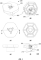
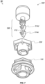
- the adjustable stopper assembly 10 shown in the Figures is assembled from a base portion 100, an intermediate portion 200 and a pin portion 300, which are assembled around a common longitudinal axis P.
- the base portion 100 is secured in a hole 402 formed in the body or structure 400 of a vehicle.
- the intermediate portion 200 and pin portion 300 are screw-threadedly connected together, whereby their relative longitudinal position can be adjusted, and the intermediate portion 200 is releasably attachable to the base portion 100.
- the base portion 100 is formed, for example, from a moulded polymer material (plastic) and has a generally cylindrical central body 102 coaxially aligned with the longitudinal axis P and a coaxial outer tubular wall 104 radially spaced apart from the central body 102 by means of four identical spacing webs 106.
- Three identical securing tabs 108 project outwardly from the outer tubular wall 104, equally angularly spaced around its periphery, and each having an inclined upper surface 110 configured to secure the base portion 100 within the hole 402 of the body or structure 400 of the vehicle, as will be explained.
- a circular flange portion 112 extends radially outwardly from the upper end of the tubular wall 104 and carries a resiliently deformable annular seal 114.
- the longitudinally uppermost end of the base portion 100 is formed into a hexagonal head 116 to facilitate rotation of the base portion 100 in order to secure it in position, as will be explained.
- a securing collar 118 is arranged coaxially with axis P and extends from the upper face of the hexagonal head 116.
- the outer face of the collar 118 is provided with three identical L-shaped recesses 120, circumferentially equidistantly spaced around the periphery.
- Each recess 120 comprises a short vertically (i.e. parallel to the longitudinal axis P ) extending portion 122 whose upper end is formed in a chamfered upper shoulder 124 of the collar 118 and whose lower end merges into a circumferentially extending portion 126.
- each recess 122, 126 is configured to receive a complementarily-shaped projection 212 extending from an inner surface of the intermediate portion 200 so as to form a bayonet-type connection during assembly.
- each recess 120 is provided with a first internal projection 128 at approximately its midpoint (i.e. at the junction between the upper recess portion 122 and the circumferential lower recess portion 126), and the circumferentially extending lower recess portion 126 of each recess 120 is provided with an identical second internal projection 130 approximately at its midpoint.
- the first and second projections 128, 130 are configured to allow the intermediate part 200 to be retained in a semi-mounted position on the base part 100, with each complementarily-shaped projection or lug 212 retainingly located between the first and second internal projections 128, 130 of the respective L-shaped recess 120.
- the central body 102 comprises a coaxial cylindrical recess 132 formed from its upper end and extending longitudinally through the central body 102 of the base portion 100, but terminating at a bottom wall 134.
- the internal side wall 136 of the recess 132 is provided with three identical, inwardly-projecting elongate projections 138 extending parallel to the longitudinal axis P along the internal side wall 136 of the recess 132.
- the intermediate portion or intermediate part 200 of this particular example embodiment is also formed from a moulded polymer material (e.g. plastic) and comprises a generally tubular body 202 and a hexagonal outwardly-extending flanged head portion 204 at its upper end (or proximal end).
- a moulded polymer material e.g. plastic
- the passage 206 of the upper portion of the tubular body 202 has a significantly smaller interior diameter than the passage 208 of the lower portion and the interior wall of the upper passage 206 is formed into a screw thread 210.
- the inner face of the lower passage 208 of the tubular body 202 is provided with three identical radially inwardly-projecting projections or lugs 212, circumferentially equidistantly spaced around the inner wall of the lower passage 208.
- Each one of the projections or lugs 212 is configured to be received in a respective one of the three L-shaped recesses 120 provided in collar 118 that is extending from the upper end of the base part 100, forming a bayonet-type connection. It is understood that number and the circumferential spacing of the L-shaped recesses 120 is matched to the number and circumferential spacing of the projections or lugs 212.
- each one of the projections 212 is adapted to operably slot / slide into the L-shaped recesses 120.
- the projection may be shaped like a hemisphere or a cuboid with rounded corners so as to facilitate sliding entry into the L-shaped recesses 120 during assembly.
- the pin part or pin portion 300 is also primarily formed from a moulded polymer material (e.g. plastic) and has a circular disc-shaped head portion 302 with a radially outwardly extending peripheral flange 304 at its lower end and an elongate stem or shank portion 306 extending coaxially along the longitudinal axis P from the under-surface of the head portion 302 (i.e. the distal end).
- a moulded polymer material e.g. plastic
- the pin part or pin portion 300 is also primarily formed from a moulded polymer material (e.g. plastic) and has a circular disc-shaped head portion 302 with a radially outwardly extending peripheral flange 304 at its lower end and an elongate stem or shank portion 306 extending coaxially along the longitudinal axis P from the under-surface of the head portion 302 (i.e. the distal end).
- the stem or shank portion 306 has a cylindrical upper portion 308, adjacent to the head portion 302 which is provided with a screw thread 310 complementary to the screw-thread 210 of upper passage 206 of the intermediate part 200, and a resiliently deformable planar lower portion 312 coaxial with the upper portion 308 at its distal end.
- a pair of identical elongate resiliently deformable planar projections 314 extend radially outwardly and towards the head portion 302 from opposite faces of the planar lower portion 312 of the stem or shank 306, forming the shape of an anchor.
- the resiliently deformable projections 314 extend from the distal end of the planar lower portion 312 and are inclined upwardly with respect to the plane of the planar lower portion 312 at a predetermined angle, for example, at an angle of approximately 30°.
- the disc-shaped head portion 302 and the cylindrical upper portion 308 of the stem or shank portion 306 are moulded so as to form a longitudinal cylindrical aperture 316 into upper portion 308 and a hexagonal aperture 318 into the head portion 302.
- the hexagonal aperture 318 may be shaped so as to receive a standard Allen key tool for adjusting the rotational position of the pin part or portion 300.
- the cylindrical upper portion 308 of the stem or shank portion 306 may be moulded around a metal bolt 320 coaxially aligned with longitudinal axis P .
- the metal bolt 320 is configured to receive a standard Allen key tool for adjusting the rotational position of the pin part or pin portion 300.
- a resiliently deformable bump cap 324 of a polymer material (e.g. a polymer foam or other deformable plastic) is secured to the upper face of the disc-shaped head portion 302 and is provided with a through hole 326 coaxially aligned with axis P so as to allow access of an Allen key tool to the hexagonal aperture 318 or hexagonal bolt head 322.
- the bump cap 324 may be glued or otherwise attached to the upper surface of the head portion 302 of the pin part 300.
- an alternative example embodiment of the adjustable stopper assembly 10' of the present invention has an equivalent base part 100', intermediate part 200' and pin part 300', with the base part 100' and the intermediate part 200' being substantially the same as the base part 100 and intermediate part 200 of adjustable stopper assembly 10.
- the alternative pin part 300' comprises a first pair of resiliently deformable projections 314a' and a second pair of resiliently deformable projections 314b', longitudinally spaced apart from and proximal to the first pair of resiliently deformable projections 314a'.
- the pair of resiliently deformable projections 314a' and 314b' are identical elongate planar projections that extend outwardly from opposite faces of the planar lower portion 312' of the stem or shank 306'.
- the projections 314a', 314b' extend in a direction inclined upwardly with respect to the planar lower portion 312'.
- the materials used for the pin part 300 are 2k components, i.e. a resilient foam polymer of the bump cap 324 combined with a resilient polymer or plastic of the head portion 302 and shank 306 (e.g. PA66-GF15% + TPV45 SHA).
- the intermediate part 200 is made from a 1k component (e.g. PP-GF30% or PA6-GF15%) and the base part 100 is made from a 2k component, i.e. a first polymer for the body (e.g. PP-GF30% or PA6-GF15%) and a second polymer for the seal (e.g.
- TPV 55 SHA TPV 55 SHA
- the pressure force on each bump cap 324 may be 500N, with a pretension on the TPV material of ⁇ 300N.
- any other suitable material may be used for any one of the components of the stopper assembly adapted to perform within the scope of the present invention.
- the intermediate part 200 and the pin part 300 are assembled by pushing the stem or shank portion 306 of the pin part 300 through the threaded upper passage 206 of the intermediate part 200.
- the footprint of the elongate planar projections 314 is wider than the diameter of the threaded upper passage 206 (i.e. the maximum extent to which they project in the lateral direction is greater than the diameter of the threaded upper passage 206), but are resiliently deformable and thus deform sufficiently (i.e. fold inwards) to allow movement through the threaded upper passage 206.
- the adjustable stopper assembly 10 is delivered with the intermediate part 200 (and the pin part 300 which is attached to the intermediate part 200) retained on the base part 100 in a semi-mounted condition. This is achieved by pushing the projections or lugs 212 of the intermediate part 200 into respective L-shaped recesses 120 of the base part 100 and over respective first internal projections 128 of the upper recess portion 122, so as to be positioned between the first internal projection 128 and the second internal projection 130 of the L-shaped recess 120. In this semi-mounted arrangement, the intermediate part 200 is "loosely" coupled with the base part 100.
- the base part 100 is separated from the semi-mounted intermediate part 200 (and the pin part 300 coupled to the intermediate part 200) by pulling the projections or lugs 212 of the intermediate part 200 over the first internal projections 128 and out of the L-shaped recesses 120.
- the lower portion of the base part 100 is then inserted into a hole or aperture 402 formed in the vehicle body 400.
- the base part 100 is then rotated, for example, by means of the hexagonal head 116, so as to contactingly engage the inclined upper surface 110 of each securing tab 108 with the under-surface of the vehicle body 402, wedgingly securing the base part 100 to the vehicle body 400 and pushing the resiliently deformable annular seal 114 into sealing engagement with the outer (upper) surface of the vehicle body 400.
- the intermediate part 200 (to which the pin part 300 is connected) is then passed through an aperture 502 of an outer panel 500, and the projections or lugs 212 of the intermediate part 200 are each aligned with and moved into the upper end of respective L-shaped recesses 120 in the securing collar 118 of the base part 100.
- the projections 212 When moving the projections or lugs 212 into the L-shaped recess 120, the projections 212 are pushed over the first internal projection 128 in the upper recess portion 122 and are subsequently rotated over the second internal projections 130 of the circumferential recess portion 126 into a locked position (e.g. clockwise when viewed from the top).
- the rotation of the intermediate part 200 may be actioned via the hexagonal flanged head 204 (e.g. using suitable tools).
- the intermediate part 200 is simply rotated anticlockwise (when viewed from the top) moving the projections or lugs 212 through the circumferential recess portion 126 and over the second internal projection 130 to then pull the projections or lugs 212 of the intermediate part 200 upwards through the upper recess portion 122 and over the first internal projection 128 and out of engagement with the base part 100.
- the planar lower portion 312 of the stem or shank 306 of the pin part 300 is received into the coaxial central body recess 132 of the central body 102 of the base part 100.
- the dimensions of the pair of resiliently deformable elongate planar projections 314 allow the pin part 300 to be rotated within the central body recess 132.
- rotation of the pin part 300 is resisted by engagement of the projections 314 with the inwardly-projecting elongate projections 138, but application of additional torque to the pin part 300 deforms the projections 314 so that they can pass over the elongate projections 138 and then spring back into the initial shape.
- the "snapping" movement of the rotating projections 314 over the internal elongate projections 138 of the central body recess 132 provides a tactile and audible feedback to the user indicating a predetermined rotation of the pin part 300 for each passing of an elongate projection 138.
- the screw-threaded engagement between the screw thread 310 and the complementarily screw-threaded upper passage 206 causes the longitudinal position of the pin part 300 relative to the intermediate part 200 to change, thus, the longitudinal position of the pin part 300 can therefore be adjusted so as to position the bump cap 324 at a desired height.
- the engagement of the resiliently deformable projections 314 with the elongate projections 138 provides a stepwise rotation (i.e. audible or tactile feedback for each step), thus, allowing a stepwise adjustment of the longitudinal position of the pin part 300.
Landscapes
- Engineering & Computer Science (AREA)
- Mechanical Engineering (AREA)
- Connection Of Plates (AREA)
- Snaps, Bayonet Connections, Set Pins, And Snap Rings (AREA)
Claims (15)
- Einstellbare Anschlaganordnung (10) für eine Fahrzeugtür oder -haube, aufweisend:ein Basisteil (100), das eine Karosserie (102) und Befestigungsmittel (108) zum Befestigen in einer Öffnung (402) in einer Karosserie (400) des Fahrzeugs aufweist;ein Stiftteil (300), das einen Kopfabschnitt (302) und einen Schaft (306) aufweist, der sich von dem Kopfabschnitt (302) erstreckt; undein Zwischenteil (200), das sich zwischen dem Basisteil (100) und dem Kopfabschnitt (302) des Stiftteils (300) befindet und lösbar an dem Basisteil (100) befestigbar ist, wobei der Schaft (306) des Stiftteils (300) zumindest einen ersten elastisch verformbaren, sich nach außen erstreckenden Vorsprung (314) an einer ersten Längsposition des Schafts (306) aufweist, dadurch gekennzeichnet, dass es einen mit einem Gewinde versehenen Abschnitt (310) zwischen dem zumindest einen ersten elastisch verformbaren Vorsprung (314) und dem Kopfabschnitt (302) des Stiftteils aufweist;wobei das Zwischenteil (200) eine mit einem Gewinde versehene Durchgangsöffnung (206) aufweist, die mit dem mit einem Gewinde versehenen Abschnitt (310) des Schafts (306) in Gewindeeingriff steht; unddas Basisteil (100) ferner eine Ausnehmung (132) aufweist, in der der zumindest eine erste elastisch verformbare Vorsprung (314) aufgenommen ist, wobei die Ausnehmung (132) einen oder mehrere sich nach innen erstreckende Vorsprünge (138) hat, die mit dem zumindest einen ersten elastisch verformbaren Vorsprung (314) in Eingriff bringbar sind, wenn das Stiftteil (300) während der Montage gedreht wird.
- Einstellbare Anschlaganordnung nach Anspruch 1, wobei die erste Längsposition ein distales Ende des Schafts ist.
- Einstellbare Anschlaganordnung nach einem der vorhergehenden Ansprüche, ferner aufweisend zumindest einen zweiten elastisch verformbaren, sich nach außen erstreckenden Vorsprung (314b') an einer zweiten Längsposition des Schafts (306), der von dem ersten Vorsprung in einer Längsrichtung des Schafts beabstandet ist, und wobei die zweite Längsposition in einer Längsrichtung proximal zu der ersten Längsposition beabstandet ist.
- Einstellbare Anschlaganordnung nach einem der vorhergehenden Ansprüche, wobei der Schaft des Stiftteils einen ersten, im Allgemeinen zylindrischen Abschnitt (308) aufweist, auf dem der mit einem Gewinde versehene Abschnitt (310) angeordnet ist.
- Einstellbare Anschlaganordnung nach Anspruch 4, wobei der Schaft des Stiftteils ferner einen elastisch verformbaren Abschnitt (312) aufweist, der sich von einem distalen Ende des im Allgemeinen zylindrischen Abschnitts (308) erstreckt.
- Einstellbare Anschlaganordnung nach Anspruch 5, wobei der elastisch verformbare Abschnitt (312) des Stiftteils eben ist.
- Einstellbare Anschlaganordnung nach einem der vorhergehenden Ansprüche, wobei der oder jeder erste elastisch verformbare, sich nach außen erstreckende Vorsprung (314) eben ist.
- Einstellbare Anschlaganordnung nach einem der Ansprüche 3 bis 7, wobei der oder jeder zweite elastisch verformbare, sich nach außen erstreckende (314b') eben ist.
- Einstellbare Anschlaganordnung nach einem der vorhergehenden Ansprüche, wobei das maximale Ausmaß, in dem der oder jeder erste elastisch verformbare, sich nach außen erstreckende Vorsprung (314) in einer seitlichen Richtung vorsteht, größer ist als der Durchmesser der mit einem Gewinde versehenen Durchgangsöffnung (206) des Zwischenteils.
- Einstellbare Anschlaganordnung nach einem der Ansprüche 3 bis 9, wobei das maximale Ausmaß, in dem der oder jeder zweite elastisch verformbare, sich nach außen erstreckende Vorsprung (314b') in einer seitlichen Richtung vorsteht, größer ist als der Durchmesser der mit einem Gewinde versehenen Durchgangsöffnung (206) des Zwischenteils.
- Einstellbare Anschlaganordnung nach einem der vorhergehenden Ansprüche, wobei der Schaft des Stiftteils zwei erste elastisch verformbare, sich nach außen erstreckende Vorsprünge (314) an der ersten Längsposition des Schafts aufweist.
- Einstellbare Anschlaganordnung nach einem der Ansprüche 3 bis 11, wobei der Schaft des Stiftteils zwei zweite elastisch verformbare, sich nach außen erstreckende Vorsprünge (314b') an der zweiten Längsposition des Schafts aufweist.
- Einstellbare Anschlaganordnung nach einem der vorhergehenden Ansprüche, ferner aufweisend eine Kappe (324), die an dem Kopfabschnitt (302) des Stiftteils befestigt ist, und wobei die Kappe (324) ein elastisch verformbares Material aufweist.
- Einstellbare Anschlaganordnung nach einem der vorhergehenden Ansprüche, wobei der Kopfabschnitt (302) des Stiftteils (300) Eingriffsmittel (318) zum Erleichtern der Drehung des Stiftteils aufweist.
- Einstellbare Anschlaganordnung nach einem der vorhergehenden Ansprüche, ferner aufweisend einen oder mehrere Vorsprünge (212) an einem von dem Zwischenteil (200) und dem Basisteil (100), wobei jeder in einer entsprechenden Ausnehmung (120) an dem anderen von dem Zwischenteil und dem Basisteil aufnehmbar ist.
Priority Applications (1)
| Application Number | Priority Date | Filing Date | Title |
|---|---|---|---|
| CN202210355497.3A CN115199164A (zh) | 2021-04-06 | 2022-04-06 | 用于车辆的可调止动器组件 |
Applications Claiming Priority (1)
| Application Number | Priority Date | Filing Date | Title |
|---|---|---|---|
| GBGB2104881.4A GB202104881D0 (en) | 2021-04-06 | 2021-04-06 | An adjustable stopper assembly for a vehicle |
Publications (2)
| Publication Number | Publication Date |
|---|---|
| EP4071329A1 EP4071329A1 (de) | 2022-10-12 |
| EP4071329B1 true EP4071329B1 (de) | 2023-11-29 |
Family
ID=75883621
Family Applications (1)
| Application Number | Title | Priority Date | Filing Date |
|---|---|---|---|
| EP22165487.4A Active EP4071329B1 (de) | 2021-04-06 | 2022-03-30 | Einstellbare stopperanordnung für ein fahrzeug |
Country Status (3)
| Country | Link |
|---|---|
| EP (1) | EP4071329B1 (de) |
| CN (1) | CN115199164A (de) |
| GB (1) | GB202104881D0 (de) |
Family Cites Families (2)
| Publication number | Priority date | Publication date | Assignee | Title |
|---|---|---|---|---|
| JP4085013B2 (ja) * | 2003-02-21 | 2008-04-30 | 日産自動車株式会社 | 緩衝装置 |
| FR3011869B1 (fr) * | 2013-10-14 | 2018-06-22 | A Raymond Et Cie | Dispositif de tampon a butee auto ajustable |
-
2021
- 2021-04-06 GB GBGB2104881.4A patent/GB202104881D0/en not_active Ceased
-
2022
- 2022-03-30 EP EP22165487.4A patent/EP4071329B1/de active Active
- 2022-04-06 CN CN202210355497.3A patent/CN115199164A/zh active Pending
Also Published As
| Publication number | Publication date |
|---|---|
| GB202104881D0 (en) | 2021-05-19 |
| CN115199164A (zh) | 2022-10-18 |
| EP4071329A1 (de) | 2022-10-12 |
Similar Documents
| Publication | Publication Date | Title |
|---|---|---|
| CN106740029B (zh) | 周向锁止机构、包括其的电池锁定装置、动力电池包及车辆 | |
| US7331157B2 (en) | Capping device with force adjustment mechanism and method of adjusting | |
| EP3084108B1 (de) | Selbsteinstellender abstandshalter | |
| US6406240B1 (en) | Fast acting nut assembly or coupling | |
| US20090138049A1 (en) | Vertebral Rod Assemblies and Methods | |
| EP2823993B1 (de) | Vorrichtung zum verstellen der rückenlehne eines fahrzeugsitzes | |
| JP7505793B2 (ja) | 屈曲可能なロック部材を有するロック機構 | |
| US4809951A (en) | Spring compressor for large coil springs | |
| US20160245008A1 (en) | Buffer device having a self-adjusting abutment | |
| US11598364B2 (en) | Locking mechanisms with deflectable lock member | |
| GB2510822A (en) | Steering column | |
| EP4071329A1 (de) | Einstellbare stopperanordnung für ein fahrzeug | |
| JPWO2020101018A1 (ja) | ステアリングコラム装置 | |
| US11306763B2 (en) | Nut | |
| US7802506B2 (en) | Upper tool device and punch therefor | |
| US20200339037A1 (en) | Fastening construction, in particular for an exterior vision unit of a motor vehicle | |
| JP7223040B2 (ja) | 中央拡張器を含むホイールロック | |
| US9782909B2 (en) | Draw stud connector | |
| US10934758B2 (en) | Desensitized adjustable bumper | |
| US12385510B2 (en) | Tolerance compensation fastening assembly | |
| US7219581B2 (en) | Adjustment tool | |
| US9279458B2 (en) | Angular positioning arrangement | |
| EP3907410A1 (de) | Federklammer | |
| EP2570701B1 (de) | Knopfaufbau | |
| EP3628507B1 (de) | Diebstahlsicherungsvorrichtung für das rad eines fahrzeugs |
Legal Events
| Date | Code | Title | Description |
|---|---|---|---|
| PUAI | Public reference made under article 153(3) epc to a published international application that has entered the european phase |
Free format text: ORIGINAL CODE: 0009012 |
|
| STAA | Information on the status of an ep patent application or granted ep patent |
Free format text: STATUS: THE APPLICATION HAS BEEN PUBLISHED |
|
| AK | Designated contracting states |
Kind code of ref document: A1 Designated state(s): AL AT BE BG CH CY CZ DE DK EE ES FI FR GB GR HR HU IE IS IT LI LT LU LV MC MK MT NL NO PL PT RO RS SE SI SK SM TR |
|
| STAA | Information on the status of an ep patent application or granted ep patent |
Free format text: STATUS: REQUEST FOR EXAMINATION WAS MADE |
|
| 17P | Request for examination filed |
Effective date: 20230331 |
|
| RBV | Designated contracting states (corrected) |
Designated state(s): AL AT BE BG CH CY CZ DE DK EE ES FI FR GB GR HR HU IE IS IT LI LT LU LV MC MK MT NL NO PL PT RO RS SE SI SK SM TR |
|
| RIN1 | Information on inventor provided before grant (corrected) |
Inventor name: SAVI, MASSIMO |
|
| RIC1 | Information provided on ipc code assigned before grant |
Ipc: E05F 5/02 20060101AFI20230525BHEP |
|
| GRAP | Despatch of communication of intention to grant a patent |
Free format text: ORIGINAL CODE: EPIDOSNIGR1 |
|
| STAA | Information on the status of an ep patent application or granted ep patent |
Free format text: STATUS: GRANT OF PATENT IS INTENDED |
|
| INTG | Intention to grant announced |
Effective date: 20230717 |
|
| P01 | Opt-out of the competence of the unified patent court (upc) registered |
Effective date: 20230825 |
|
| GRAS | Grant fee paid |
Free format text: ORIGINAL CODE: EPIDOSNIGR3 |
|
| GRAA | (expected) grant |
Free format text: ORIGINAL CODE: 0009210 |
|
| STAA | Information on the status of an ep patent application or granted ep patent |
Free format text: STATUS: THE PATENT HAS BEEN GRANTED |
|
| AK | Designated contracting states |
Kind code of ref document: B1 Designated state(s): AL AT BE BG CH CY CZ DE DK EE ES FI FR GB GR HR HU IE IS IT LI LT LU LV MC MK MT NL NO PL PT RO RS SE SI SK SM TR |
|
| REG | Reference to a national code |
Ref country code: GB Ref legal event code: FG4D |
|
| REG | Reference to a national code |
Ref country code: CH Ref legal event code: EP |
|
| REG | Reference to a national code |
Ref country code: DE Ref legal event code: R096 Ref document number: 602022001131 Country of ref document: DE |
|
| REG | Reference to a national code |
Ref country code: IE Ref legal event code: FG4D |
|
| REG | Reference to a national code |
Ref country code: SE Ref legal event code: TRGR |
|
| REG | Reference to a national code |
Ref country code: LT Ref legal event code: MG9D |
|
| REG | Reference to a national code |
Ref country code: NL Ref legal event code: MP Effective date: 20231129 |
|
| PG25 | Lapsed in a contracting state [announced via postgrant information from national office to epo] |
Ref country code: GR Free format text: LAPSE BECAUSE OF FAILURE TO SUBMIT A TRANSLATION OF THE DESCRIPTION OR TO PAY THE FEE WITHIN THE PRESCRIBED TIME-LIMIT Effective date: 20240301 |
|
| PG25 | Lapsed in a contracting state [announced via postgrant information from national office to epo] |
Ref country code: IS Free format text: LAPSE BECAUSE OF FAILURE TO SUBMIT A TRANSLATION OF THE DESCRIPTION OR TO PAY THE FEE WITHIN THE PRESCRIBED TIME-LIMIT Effective date: 20240329 |
|
| PG25 | Lapsed in a contracting state [announced via postgrant information from national office to epo] |
Ref country code: LT Free format text: LAPSE BECAUSE OF FAILURE TO SUBMIT A TRANSLATION OF THE DESCRIPTION OR TO PAY THE FEE WITHIN THE PRESCRIBED TIME-LIMIT Effective date: 20231129 |
|
| PG25 | Lapsed in a contracting state [announced via postgrant information from national office to epo] |
Ref country code: ES Free format text: LAPSE BECAUSE OF FAILURE TO SUBMIT A TRANSLATION OF THE DESCRIPTION OR TO PAY THE FEE WITHIN THE PRESCRIBED TIME-LIMIT Effective date: 20231129 |
|
| PG25 | Lapsed in a contracting state [announced via postgrant information from national office to epo] |
Ref country code: LT Free format text: LAPSE BECAUSE OF FAILURE TO SUBMIT A TRANSLATION OF THE DESCRIPTION OR TO PAY THE FEE WITHIN THE PRESCRIBED TIME-LIMIT Effective date: 20231129 Ref country code: IS Free format text: LAPSE BECAUSE OF FAILURE TO SUBMIT A TRANSLATION OF THE DESCRIPTION OR TO PAY THE FEE WITHIN THE PRESCRIBED TIME-LIMIT Effective date: 20240329 Ref country code: GR Free format text: LAPSE BECAUSE OF FAILURE TO SUBMIT A TRANSLATION OF THE DESCRIPTION OR TO PAY THE FEE WITHIN THE PRESCRIBED TIME-LIMIT Effective date: 20240301 Ref country code: ES Free format text: LAPSE BECAUSE OF FAILURE TO SUBMIT A TRANSLATION OF THE DESCRIPTION OR TO PAY THE FEE WITHIN THE PRESCRIBED TIME-LIMIT Effective date: 20231129 Ref country code: BG Free format text: LAPSE BECAUSE OF FAILURE TO SUBMIT A TRANSLATION OF THE DESCRIPTION OR TO PAY THE FEE WITHIN THE PRESCRIBED TIME-LIMIT Effective date: 20240229 |
|
| REG | Reference to a national code |
Ref country code: AT Ref legal event code: MK05 Ref document number: 1636274 Country of ref document: AT Kind code of ref document: T Effective date: 20231129 |
|
| PG25 | Lapsed in a contracting state [announced via postgrant information from national office to epo] |
Ref country code: NL Free format text: LAPSE BECAUSE OF FAILURE TO SUBMIT A TRANSLATION OF THE DESCRIPTION OR TO PAY THE FEE WITHIN THE PRESCRIBED TIME-LIMIT Effective date: 20231129 |
|
| PG25 | Lapsed in a contracting state [announced via postgrant information from national office to epo] |
Ref country code: RS Free format text: LAPSE BECAUSE OF FAILURE TO SUBMIT A TRANSLATION OF THE DESCRIPTION OR TO PAY THE FEE WITHIN THE PRESCRIBED TIME-LIMIT Effective date: 20231129 Ref country code: PL Free format text: LAPSE BECAUSE OF FAILURE TO SUBMIT A TRANSLATION OF THE DESCRIPTION OR TO PAY THE FEE WITHIN THE PRESCRIBED TIME-LIMIT Effective date: 20231129 Ref country code: NO Free format text: LAPSE BECAUSE OF FAILURE TO SUBMIT A TRANSLATION OF THE DESCRIPTION OR TO PAY THE FEE WITHIN THE PRESCRIBED TIME-LIMIT Effective date: 20240229 Ref country code: NL Free format text: LAPSE BECAUSE OF FAILURE TO SUBMIT A TRANSLATION OF THE DESCRIPTION OR TO PAY THE FEE WITHIN THE PRESCRIBED TIME-LIMIT Effective date: 20231129 Ref country code: LV Free format text: LAPSE BECAUSE OF FAILURE TO SUBMIT A TRANSLATION OF THE DESCRIPTION OR TO PAY THE FEE WITHIN THE PRESCRIBED TIME-LIMIT Effective date: 20231129 Ref country code: HR Free format text: LAPSE BECAUSE OF FAILURE TO SUBMIT A TRANSLATION OF THE DESCRIPTION OR TO PAY THE FEE WITHIN THE PRESCRIBED TIME-LIMIT Effective date: 20231129 |
|
| PGFP | Annual fee paid to national office [announced via postgrant information from national office to epo] |
Ref country code: SE Payment date: 20240327 Year of fee payment: 3 |
|
| PG25 | Lapsed in a contracting state [announced via postgrant information from national office to epo] |
Ref country code: DK Free format text: LAPSE BECAUSE OF FAILURE TO SUBMIT A TRANSLATION OF THE DESCRIPTION OR TO PAY THE FEE WITHIN THE PRESCRIBED TIME-LIMIT Effective date: 20231129 |
|
| PG25 | Lapsed in a contracting state [announced via postgrant information from national office to epo] |
Ref country code: CZ Free format text: LAPSE BECAUSE OF FAILURE TO SUBMIT A TRANSLATION OF THE DESCRIPTION OR TO PAY THE FEE WITHIN THE PRESCRIBED TIME-LIMIT Effective date: 20231129 Ref country code: AT Free format text: LAPSE BECAUSE OF FAILURE TO SUBMIT A TRANSLATION OF THE DESCRIPTION OR TO PAY THE FEE WITHIN THE PRESCRIBED TIME-LIMIT Effective date: 20231129 |
|
| PG25 | Lapsed in a contracting state [announced via postgrant information from national office to epo] |
Ref country code: SK Free format text: LAPSE BECAUSE OF FAILURE TO SUBMIT A TRANSLATION OF THE DESCRIPTION OR TO PAY THE FEE WITHIN THE PRESCRIBED TIME-LIMIT Effective date: 20231129 |
|
| PG25 | Lapsed in a contracting state [announced via postgrant information from national office to epo] |
Ref country code: SM Free format text: LAPSE BECAUSE OF FAILURE TO SUBMIT A TRANSLATION OF THE DESCRIPTION OR TO PAY THE FEE WITHIN THE PRESCRIBED TIME-LIMIT Effective date: 20231129 Ref country code: SK Free format text: LAPSE BECAUSE OF FAILURE TO SUBMIT A TRANSLATION OF THE DESCRIPTION OR TO PAY THE FEE WITHIN THE PRESCRIBED TIME-LIMIT Effective date: 20231129 Ref country code: RO Free format text: LAPSE BECAUSE OF FAILURE TO SUBMIT A TRANSLATION OF THE DESCRIPTION OR TO PAY THE FEE WITHIN THE PRESCRIBED TIME-LIMIT Effective date: 20231129 Ref country code: IT Free format text: LAPSE BECAUSE OF FAILURE TO SUBMIT A TRANSLATION OF THE DESCRIPTION OR TO PAY THE FEE WITHIN THE PRESCRIBED TIME-LIMIT Effective date: 20231129 Ref country code: EE Free format text: LAPSE BECAUSE OF FAILURE TO SUBMIT A TRANSLATION OF THE DESCRIPTION OR TO PAY THE FEE WITHIN THE PRESCRIBED TIME-LIMIT Effective date: 20231129 Ref country code: DK Free format text: LAPSE BECAUSE OF FAILURE TO SUBMIT A TRANSLATION OF THE DESCRIPTION OR TO PAY THE FEE WITHIN THE PRESCRIBED TIME-LIMIT Effective date: 20231129 Ref country code: CZ Free format text: LAPSE BECAUSE OF FAILURE TO SUBMIT A TRANSLATION OF THE DESCRIPTION OR TO PAY THE FEE WITHIN THE PRESCRIBED TIME-LIMIT Effective date: 20231129 Ref country code: AT Free format text: LAPSE BECAUSE OF FAILURE TO SUBMIT A TRANSLATION OF THE DESCRIPTION OR TO PAY THE FEE WITHIN THE PRESCRIBED TIME-LIMIT Effective date: 20231129 |
|
| PG25 | Lapsed in a contracting state [announced via postgrant information from national office to epo] |
Ref country code: PT Free format text: LAPSE BECAUSE OF FAILURE TO SUBMIT A TRANSLATION OF THE DESCRIPTION OR TO PAY THE FEE WITHIN THE PRESCRIBED TIME-LIMIT Effective date: 20240401 |
|
| PG25 | Lapsed in a contracting state [announced via postgrant information from national office to epo] |
Ref country code: PT Free format text: LAPSE BECAUSE OF FAILURE TO SUBMIT A TRANSLATION OF THE DESCRIPTION OR TO PAY THE FEE WITHIN THE PRESCRIBED TIME-LIMIT Effective date: 20240401 |
|
| REG | Reference to a national code |
Ref country code: DE Ref legal event code: R097 Ref document number: 602022001131 Country of ref document: DE |
|
| REG | Reference to a national code |
Ref country code: DE Ref legal event code: R119 Ref document number: 602022001131 Country of ref document: DE |
|
| PLBE | No opposition filed within time limit |
Free format text: ORIGINAL CODE: 0009261 |
|
| STAA | Information on the status of an ep patent application or granted ep patent |
Free format text: STATUS: NO OPPOSITION FILED WITHIN TIME LIMIT |
|
| PG25 | Lapsed in a contracting state [announced via postgrant information from national office to epo] |
Ref country code: SI Free format text: LAPSE BECAUSE OF FAILURE TO SUBMIT A TRANSLATION OF THE DESCRIPTION OR TO PAY THE FEE WITHIN THE PRESCRIBED TIME-LIMIT Effective date: 20231129 |
|
| PG25 | Lapsed in a contracting state [announced via postgrant information from national office to epo] |
Ref country code: SI Free format text: LAPSE BECAUSE OF FAILURE TO SUBMIT A TRANSLATION OF THE DESCRIPTION OR TO PAY THE FEE WITHIN THE PRESCRIBED TIME-LIMIT Effective date: 20231129 |
|
| 26N | No opposition filed |
Effective date: 20240830 |
|
| PG25 | Lapsed in a contracting state [announced via postgrant information from national office to epo] |
Ref country code: LU Free format text: LAPSE BECAUSE OF NON-PAYMENT OF DUE FEES Effective date: 20240330 |
|
| PG25 | Lapsed in a contracting state [announced via postgrant information from national office to epo] |
Ref country code: MC Free format text: LAPSE BECAUSE OF FAILURE TO SUBMIT A TRANSLATION OF THE DESCRIPTION OR TO PAY THE FEE WITHIN THE PRESCRIBED TIME-LIMIT Effective date: 20231129 |
|
| PG25 | Lapsed in a contracting state [announced via postgrant information from national office to epo] |
Ref country code: MC Free format text: LAPSE BECAUSE OF FAILURE TO SUBMIT A TRANSLATION OF THE DESCRIPTION OR TO PAY THE FEE WITHIN THE PRESCRIBED TIME-LIMIT Effective date: 20231129 Ref country code: LU Free format text: LAPSE BECAUSE OF NON-PAYMENT OF DUE FEES Effective date: 20240330 |
|
| REG | Reference to a national code |
Ref country code: BE Ref legal event code: MM Effective date: 20240331 |
|
| PG25 | Lapsed in a contracting state [announced via postgrant information from national office to epo] |
Ref country code: DE Free format text: LAPSE BECAUSE OF NON-PAYMENT OF DUE FEES Effective date: 20241001 |
|
| PG25 | Lapsed in a contracting state [announced via postgrant information from national office to epo] |
Ref country code: BE Free format text: LAPSE BECAUSE OF NON-PAYMENT OF DUE FEES Effective date: 20240331 |
|
| PG25 | Lapsed in a contracting state [announced via postgrant information from national office to epo] |
Ref country code: FR Free format text: LAPSE BECAUSE OF NON-PAYMENT OF DUE FEES Effective date: 20240331 |
|
| PG25 | Lapsed in a contracting state [announced via postgrant information from national office to epo] |
Ref country code: IE Free format text: LAPSE BECAUSE OF NON-PAYMENT OF DUE FEES Effective date: 20240330 |
|
| PG25 | Lapsed in a contracting state [announced via postgrant information from national office to epo] |
Ref country code: IE Free format text: LAPSE BECAUSE OF NON-PAYMENT OF DUE FEES Effective date: 20240330 Ref country code: FR Free format text: LAPSE BECAUSE OF NON-PAYMENT OF DUE FEES Effective date: 20240331 Ref country code: DE Free format text: LAPSE BECAUSE OF NON-PAYMENT OF DUE FEES Effective date: 20241001 Ref country code: BE Free format text: LAPSE BECAUSE OF NON-PAYMENT OF DUE FEES Effective date: 20240331 |
|
| PG25 | Lapsed in a contracting state [announced via postgrant information from national office to epo] |
Ref country code: CY Free format text: LAPSE BECAUSE OF FAILURE TO SUBMIT A TRANSLATION OF THE DESCRIPTION OR TO PAY THE FEE WITHIN THE PRESCRIBED TIME-LIMIT; INVALID AB INITIO Effective date: 20220330 |
|
| PG25 | Lapsed in a contracting state [announced via postgrant information from national office to epo] |
Ref country code: FI Free format text: LAPSE BECAUSE OF FAILURE TO SUBMIT A TRANSLATION OF THE DESCRIPTION OR TO PAY THE FEE WITHIN THE PRESCRIBED TIME-LIMIT Effective date: 20231129 |
|
| REG | Reference to a national code |
Ref country code: CH Ref legal event code: H13 Free format text: ST27 STATUS EVENT CODE: U-0-0-H10-H13 (AS PROVIDED BY THE NATIONAL OFFICE) Effective date: 20251023 |
|
| REG | Reference to a national code |
Ref country code: SE Ref legal event code: EUG |
|
| PG25 | Lapsed in a contracting state [announced via postgrant information from national office to epo] |
Ref country code: TR Free format text: LAPSE BECAUSE OF FAILURE TO SUBMIT A TRANSLATION OF THE DESCRIPTION OR TO PAY THE FEE WITHIN THE PRESCRIBED TIME-LIMIT Effective date: 20231129 |
|
| PG25 | Lapsed in a contracting state [announced via postgrant information from national office to epo] |
Ref country code: CH Free format text: LAPSE BECAUSE OF NON-PAYMENT OF DUE FEES Effective date: 20250331 |
|
| PG25 | Lapsed in a contracting state [announced via postgrant information from national office to epo] |
Ref country code: SE Free format text: LAPSE BECAUSE OF NON-PAYMENT OF DUE FEES Effective date: 20250331 |