EP4071034A1 - Spoiler and vehicle tailgate assembly - Google Patents
Spoiler and vehicle tailgate assembly Download PDFInfo
- Publication number
- EP4071034A1 EP4071034A1 EP22165615.0A EP22165615A EP4071034A1 EP 4071034 A1 EP4071034 A1 EP 4071034A1 EP 22165615 A EP22165615 A EP 22165615A EP 4071034 A1 EP4071034 A1 EP 4071034A1
- Authority
- EP
- European Patent Office
- Prior art keywords
- spoiler
- mounting part
- flow guide
- embedded
- vehicle
- Prior art date
- Legal status (The legal status is an assumption and is not a legal conclusion. Google has not performed a legal analysis and makes no representation as to the accuracy of the status listed.)
- Pending
Links
- 238000000071 blow moulding Methods 0.000 claims description 7
- 238000003780 insertion Methods 0.000 claims description 3
- 230000037431 insertion Effects 0.000 claims description 3
- 239000000428 dust Substances 0.000 description 5
- 239000011521 glass Substances 0.000 description 5
- 238000009434 installation Methods 0.000 description 4
- 238000005452 bending Methods 0.000 description 3
- 230000014509 gene expression Effects 0.000 description 3
- 238000001746 injection moulding Methods 0.000 description 3
- 239000002184 metal Substances 0.000 description 3
- 238000005265 energy consumption Methods 0.000 description 2
- 238000000034 method Methods 0.000 description 2
- 238000005406 washing Methods 0.000 description 2
- 239000006260 foam Substances 0.000 description 1
- 239000000463 material Substances 0.000 description 1
- 230000003014 reinforcing effect Effects 0.000 description 1
- XLYOFNOQVPJJNP-UHFFFAOYSA-N water Chemical compound O XLYOFNOQVPJJNP-UHFFFAOYSA-N 0.000 description 1
Images


Classifications
-
- B—PERFORMING OPERATIONS; TRANSPORTING
- B62—LAND VEHICLES FOR TRAVELLING OTHERWISE THAN ON RAILS
- B62D—MOTOR VEHICLES; TRAILERS
- B62D35/00—Vehicle bodies characterised by streamlining
- B62D35/007—Rear spoilers
-
- B—PERFORMING OPERATIONS; TRANSPORTING
- B62—LAND VEHICLES FOR TRAVELLING OTHERWISE THAN ON RAILS
- B62D—MOTOR VEHICLES; TRAILERS
- B62D37/00—Stabilising vehicle bodies without controlling suspension arrangements
- B62D37/02—Stabilising vehicle bodies without controlling suspension arrangements by aerodynamic means
-
- B—PERFORMING OPERATIONS; TRANSPORTING
- B60—VEHICLES IN GENERAL
- B60J—WINDOWS, WINDSCREENS, NON-FIXED ROOFS, DOORS, OR SIMILAR DEVICES FOR VEHICLES; REMOVABLE EXTERNAL PROTECTIVE COVERINGS SPECIALLY ADAPTED FOR VEHICLES
- B60J5/00—Doors
- B60J5/10—Doors arranged at the vehicle rear
-
- Y—GENERAL TAGGING OF NEW TECHNOLOGICAL DEVELOPMENTS; GENERAL TAGGING OF CROSS-SECTIONAL TECHNOLOGIES SPANNING OVER SEVERAL SECTIONS OF THE IPC; TECHNICAL SUBJECTS COVERED BY FORMER USPC CROSS-REFERENCE ART COLLECTIONS [XRACs] AND DIGESTS
- Y02—TECHNOLOGIES OR APPLICATIONS FOR MITIGATION OR ADAPTATION AGAINST CLIMATE CHANGE
- Y02T—CLIMATE CHANGE MITIGATION TECHNOLOGIES RELATED TO TRANSPORTATION
- Y02T10/00—Road transport of goods or passengers
- Y02T10/80—Technologies aiming to reduce greenhouse gasses emissions common to all road transportation technologies
- Y02T10/82—Elements for improving aerodynamics
Definitions
- the present application generally relates to the field of vehicle body parts, and more particularly, to a spoiler and a vehicle tailgate assembly including the spoiler.
- a vehicle spoiler refers to a component similar to an inverted aircraft empennage mounted on the tailgate of a vehicle, and the component at this position is also called a tail wing.
- a vehicle will encounter air resistance in the process of traveling, and this resistance can be divided into three component forces: longitudinal, lateral and vertically upward. The faster the vehicle speed, the greater the air resistance.
- a spoiler is provided at the rear of the vehicle, which is configured to cause the air flow to produce a fourth force, that is, adhesion force to the ground, on the vehicle.
- This adhesion force can counterbalance part of the aerodynamic lift and restrain the vehicle from lifting, so that the vehicle can travel attaching to the road, thereby improving the traveling stability of the vehicle.
- the spoiler also helps to save energy consumption.
- the spoiler should occupy an area which can minimize the impact on the driver's rear vision.
- the spoiler preferably also serves to guide the airflow to the rear of the vehicle body and remove dust from the tailgate glass by means of the airflow, so as to further avoid dust from adhering and further affecting the driver's rear vision.
- the metal spoiler includes an outer spoiler plate, an inner spoiler plate, and even a middle reinforcing spoiler plate.
- the rigidity of the metal spoiler is excellent, but the structure thereof is complicated and the weight thereof is heavy, and some fastener installation points may be rusted.
- the plastic spoiler is generally formed by the injection molding process.
- the spoiler formed by the injection molding process generally has a poor appearance and poor rigidity.
- the weight of the spoiler formed by the injection molding process cannot meet the requirements neither.
- An object of the present application is to overcome the above-mentioned disadvantages of the prior art, and to propose a spoiler and a vehicle tailgate assembly including the spoiler, wherein the spoiler is a single hollow member, and has a light weight and smooth lines.
- a spoiler which is adapted to be provided on the top of a vehicle tailgate assembly.
- the spoiler is an integral single hollow member and includes:
- the present application may further include one or more of the following optional forms.
- the cross-sectional size of the flow guide part is smaller than that of the mounting part.
- each mounting part is provided with a plurality of embedded fasteners and at least one pre-positioning element, and the plurality of embedded fasteners are arranged at intervals along the mounting part.
- the mounting part is provided with a bent portion away from the flow guide part, and at least two embedded fasteners are arranged adjacent to the bent portion.
- the mounting part is further provided with an anti-vibration element, and the anti-vibration element extends along at least a portion of the edge of the mounting part.
- the spoiler is a single member manufactured by hollow blow-molding process, and the embedded fasteners and the pre-positioning element are embedded in the spoiler during the hollow blow-molding process.
- the embedded fasteners are nuts, and the spoiler hermetically surrounds the nuts.
- the pre-positioning element includes a head extending away from the spoiler, and the head includes an insertion guiding surface and a clamping portion.
- a vehicle tailgate assembly which at least includes a tailgate inner panel, a carrying base, and the spoiler according to the first aspect of the present application.
- the carrying base is symmetrically connected at two ends of the top of the tailgate inner panel, and the mounting part of the spoiler is joined with the carrying base to form an air flow gap by the guiding surface of the flow guide part.
- the spoiler of the present application is an integral single hollow member, which not only reduces the self-weight of the spoiler, but also allows the spoiler to have a better streamline shape.
- the mounting part of the spoiler is arranged at two ends of the flow guide part, forming the air flow gap on the vehicle tailgate assembly. Further, the shielding of the spoiler on the vehicle tailgate assembly is minimized through the reasonable arrangement of installation points on the mounting part, so as to avoid affecting the driver's rear vision.
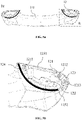
- FIG. 1-3 show a vehicle tailgate assembly 100 according to an embodiment of the present application.
- the vehicle tailgate assembly 100 at least includes a spoiler 10, a tailgate inner panel 20, and two carrying bases 30.
- the two carrying bases 30 are symmetrically connected at two ends of the top of the tailgate inner panel 20, and the spoiler 10 is connected to the two carrying bases 30.
- the spoiler 10 is arranged on the top of the vehicle tailgate assembly 100 by being connected to the carrying bases 30, as shown in FIG. 6a and 7a of the spoiler 10 installed on the vehicle.
- the top of the spoiler 10 is defined as the part that is visible from the outside of the vehicle, that is, the top of the spoiler 10 faces away from the tailgate inner panel 20.
- the bottom of the spoiler 10 is defined as the part that is not easily visible from the outside of the vehicle, that is, the bottom of the spoiler 10 faces the tailgate inner panel 20.
- FIG. 4a is a top view of the spoiler 10
- FIG. 5a is a bottom view of the spoiler 10.
- the spoiler 10 includes a flow guide part 11 and a mounting part 12.
- the mounting part 12 is symmetrically provided at two ends of the flow guide part 11.
- the flow guide part 11 is provided with an arc-shaped recess 111.
- the arc-shaped recess 111 has a guiding surface 1110 smoothly extending from the top of the spoiler 10 to the bottom of the spoiler 10.
- the guiding surface 1110 at least includes a top guiding surface 1111 and a bottom guiding surface 1112.
- the guiding surface 1110 of the flow guide part 11 is configured to form an air flow gap 40 on the vehicle tailgate assembly 100, so as to guide the airflow to wash away the dust on the vehicle tailgate assembly 100.
- the air flow gap is formed between the bottom guiding surface 1112 of the flow guide part 11 and the glass to guide the air flow to wash away dust on the glass, so that the rear wiper can be dispensed with.
- the air flow is divided on the guiding surface 1110, one part flows along the top guiding surface 1111 ,and the other part enters the air flow gap 40 along the bottom guiding surface 1112.
- the spoiler 10 is an integral single hollow member.
- the spoiler 10 is a single member manufactured by hollow blow-molding process.
- the spoiler 10 will have a lighter weight, a better streamline shape and a better sectional bending resistance.
- the cross-sectional size of the flow guide part 11 is set to be smaller than that of the mounting part 12 to form an appropriate air flow gap 40.
- the mounting part 12 is arranged at two ends of the flow guide part 11, there is no need to provide installation points on the flow guide part 11, so the flow guide part 11 can have a smaller cross-sectional size while ensuring the cross-sectional bending resistance of the flow guide part 11, which helps reduce the impact of the spoiler 10 on the driver's rear vision.
- the mounting part 12 of the spoiler 10 is provided with a plurality of embedded fasteners 121 and at least one pre-positioning element 122.
- the pre-positioning element 122 is preferably arranged in the middle of the mounting part 12, in order to ensure that, when the mounting part 12 is in contact with the carrying base 30, the mounting part 12 is pre-tightened on the carrying base 30 by the pre-positioning element 122.
- the pre-positioning element 122 is preferably arranged in the middle of the mounting part 12, in order to ensure that, when the mounting part 12 is in contact with the carrying base 30, the mounting part 12 is pre-tightened on the carrying base 30 by the pre-positioning element 122.
- the pre-positioning element 122 includes a head 1220 extending away from the spoiler 10, and the head 1220 includes an insertion guiding surface 1221 and a clamping portion 1222, so as to smoothly guide the pre-positioning element 122 to be inserted into and clamped in a pre-positioning groove 31 of the carrying base 30.
- a plurality of embedded fasteners 121 are arranged at intervals along the mounting part 12.
- the mounting part 12 is provided with three embedded fasteners, namely a first embedded fastener 1211, a second embedded fastener 1212 and a third embedded fastener 1213.
- the first embedded fastener 1211, the second embedded fastener 1212 and the third embedded fastener 1213 are all constructed as nuts.
- the embedded fasteners may all be constructed as bolts; or, part of the embedded fasteners may be constructed as nuts, and other part of the embedded fasteners may be constructed as bolts.
- the mounting part 12 is provided with a bent portion 123 away from the arc-shaped recess 111 of the flow guide part 11, and at least two embedded fasteners are arranged adjacent to the bent portion 123.
- the second embedded fastener 1212 and the third embedded fastener 1213 are arranged adjacent to the bent portion 123.
- the provision of the bent portion 123 allows an installation direction set by the third embedded fastener 1213 to be different from that set by the second embedded fastener 1212.
- the third embedded fastener 1213 is installed substantially in the width direction of the vehicle.
- the structural strength of the mounting part can be improved by providing a fastener that is loaded with a force substantially in the width direction of the vehicle at a position of each mounting part 12 close to the vehicle side.
- the above configuration ensures that the spoiler 10 can withstand the pressing force exerted on it by the washing brush from two sides of the vehicle and that the spoiler 10 will not be bent and deformed in the width direction of the vehicle.
- first embedded fastener 1211 is arranged as close to the middle of the spoiler 10 as possible, that is, as close to the flow guide part 11 as possible, so that the first embedded fastener 1211, the second embedded fastener 1212 and the third embedded fastener 1213 form a triangle with a larger area, which ensures the stability of the connection without further increasing the number of embedded fasteners.
- a fastening bolt 32 passes through the carrying base 30 to engage with the embedded fastener 121
- the embedded fastener 121 constructed as a nut is preferably embedded in the spoiler 10 during the hollow blow-molding process, and the spoiler 10 hermetically surrounds the embedded fastener 121.
- the pre-positioning element 122 and the embedded fastener 121 are embedded in the spoiler 10 in the hollow blow-molding process at the same time.
- the spoiler 10 formed integrally has a sealed hollow chamber, thereby isolating the dust and water vapor from the hollow chamber.
- the pre-positioning element 122 is connected to the spoiler 10 by means of bonding.
- the mounting part 12 is further provided with an anti-vibration element 124, and the anti-vibration element 124 extends along at least a portion of the edge of the mounting part.
- the anti-vibration element 124 may be selected as anti-vibration foam
- the first embedded fastener 1211, the second embedded fastener 1212 and the third embedded fastener 1213 are optionally arranged along a front edge 1251 (also referred to as an upper edge) of the mounting part 12
- the anti-vibration element 124 is optionally arranged along a rear edge 1252 (also referred to as a lower edge) of the mounting part 12.
- the anti-vibration element 124 is arranged in an arc shape along the rear edge 1252 to effectively resist vibration by disposing the anti-vibration element 124 at the position where the rear edge 1252 of the mounting part 12 contacts the carrying base 30.
- the rear edge 1252 of the mounting part 12 can be as close to the front edge 1251 as possible, so as to reduce the contact area between the mounting part 12 and the carrying base 30, and further avoid the influence of the spoiler 10 on the driver's rear vision.
- the spoiler of the present application is an integral single hollow member, which not only can easily control the gap and flushness of the spoiler on the vehicle tailgate assembly, allowing the mounting part of the spoiler to be completely fitted with the carrying base, but also can reduce the weight of the spoiler to the greatest extent and ensure sufficient cross-sectional bending resistance.
- FIGS. 1 to 7d only illustrate the optional shape, size and arrangement of each optional component of the spoiler according to the present application.
- these embodiments are merely intended to illustrate, rather than limit.
- Other shapes, sizes and arrangements may be adopted without departing from the idea and scope of the present application.
Landscapes
- Engineering & Computer Science (AREA)
- Mechanical Engineering (AREA)
- Chemical & Material Sciences (AREA)
- Combustion & Propulsion (AREA)
- Transportation (AREA)
- Physics & Mathematics (AREA)
- Fluid Mechanics (AREA)
- Connection Of Plates (AREA)
Abstract
Description
- The present application generally relates to the field of vehicle body parts, and more particularly, to a spoiler and a vehicle tailgate assembly including the spoiler.
- A vehicle spoiler refers to a component similar to an inverted aircraft empennage mounted on the tailgate of a vehicle, and the component at this position is also called a tail wing.
- It is already known that a vehicle will encounter air resistance in the process of traveling, and this resistance can be divided into three component forces: longitudinal, lateral and vertically upward. The faster the vehicle speed, the greater the air resistance. In order to effectively reduce and overcome the influence of air resistance when the vehicle is traveling at high speed, a spoiler is provided at the rear of the vehicle, which is configured to cause the air flow to produce a fourth force, that is, adhesion force to the ground, on the vehicle. This adhesion force can counterbalance part of the aerodynamic lift and restrain the vehicle from lifting, so that the vehicle can travel attaching to the road, thereby improving the traveling stability of the vehicle. In addition to improving traveling stability, the spoiler also helps to save energy consumption.
- From a structural point of view, while improving traveling stability and saving energy consumption, the spoiler should occupy an area which can minimize the impact on the driver's rear vision. For a vehicle tailgate assembly with glass, the spoiler preferably also serves to guide the airflow to the rear of the vehicle body and remove dust from the tailgate glass by means of the airflow, so as to further avoid dust from adhering and further affecting the driver's rear vision. In addition, from the material point of view, in the existing design, there are metal spoiler and plastic spoiler. The metal spoiler includes an outer spoiler plate, an inner spoiler plate, and even a middle reinforcing spoiler plate. The rigidity of the metal spoiler is excellent, but the structure thereof is complicated and the weight thereof is heavy, and some fastener installation points may be rusted. The plastic spoiler is generally formed by the injection molding process. The spoiler formed by the injection molding process generally has a poor appearance and poor rigidity. For the vehicle body design with lightweight requirements, the weight of the spoiler formed by the injection molding process cannot meet the requirements neither.
- An object of the present application is to overcome the above-mentioned disadvantages of the prior art, and to propose a spoiler and a vehicle tailgate assembly including the spoiler, wherein the spoiler is a single hollow member, and has a light weight and smooth lines.
- To this end, according to a first aspect of the present application, a spoiler is provided, which is adapted to be provided on the top of a vehicle tailgate assembly. The spoiler is an integral single hollow member and includes:
- a flow guide part provided with an arc-shaped recess, wherein the arc-shaped recess has a guiding surface smoothly extending from the top of the spoiler to the bottom of the spoiler; and
- a mounting part symmetrically provided at two ends of the flow guide part;
- wherein the mounting part is adapted to be mounted to the vehicle tailgate assembly and forms an air flow gap on the vehicle tailgate assembly by means of the guiding surface of the flow guide part.
- According to the above technical concept, the present application may further include one or more of the following optional forms.
- In some optional forms, the cross-sectional size of the flow guide part is smaller than that of the mounting part.
- In some optional forms, each mounting part is provided with a plurality of embedded fasteners and at least one pre-positioning element, and the plurality of embedded fasteners are arranged at intervals along the mounting part.
- In some optional forms, the mounting part is provided with a bent portion away from the flow guide part, and at least two embedded fasteners are arranged adjacent to the bent portion.
- In some optional forms, the mounting part is further provided with an anti-vibration element, and the anti-vibration element extends along at least a portion of the edge of the mounting part.
- In some optional forms, the spoiler is a single member manufactured by hollow blow-molding process, and the embedded fasteners and the pre-positioning element are embedded in the spoiler during the hollow blow-molding process.
- In some optional forms, the embedded fasteners are nuts, and the spoiler hermetically surrounds the nuts.
- In some optional forms, the pre-positioning element includes a head extending away from the spoiler, and the head includes an insertion guiding surface and a clamping portion.
- According to another aspect of the present application, a vehicle tailgate assembly is further provided, which at least includes a tailgate inner panel, a carrying base, and the spoiler according to the first aspect of the present application. The carrying base is symmetrically connected at two ends of the top of the tailgate inner panel, and the mounting part of the spoiler is joined with the carrying base to form an air flow gap by the guiding surface of the flow guide part.
- The spoiler of the present application is an integral single hollow member, which not only reduces the self-weight of the spoiler, but also allows the spoiler to have a better streamline shape. The mounting part of the spoiler is arranged at two ends of the flow guide part, forming the air flow gap on the vehicle tailgate assembly. Further, the shielding of the spoiler on the vehicle tailgate assembly is minimized through the reasonable arrangement of installation points on the mounting part, so as to avoid affecting the driver's rear vision.
- Other features and advantages of the present application will be readily understood through the following preferred embodiments described in detail with reference to the accompanying drawings, in which the same reference numerals indicate the same or similar components.
-
FIG. 1 is a schematic view of a vehicle tailgate assembly including a spoiler according to an embodiment of the present application; -
FIG. 2 is the schematic view of the spoiler disassembled from the vehicle tailgate assembly shown inFIG. 1 ; -
FIG. 3 is a partially exploded view of the vehicle tailgate assembly without the spoiler; -
FIG. 4a is a top view of the spoiler according to an embodiment of the present application,FIG. 4b is a sectional view at section line A-A inFIG. 4a ; -
FIG. 5a is a bottom view of the spoiler shown inFIG. 4a ,FIG. 5b is a partial enlarged view at part B inFIG. 5a ; -
FIG. 6a is a schematic view of the spoiler mounted to the vehicle;FIG. 6b is a sectional view at section line C-C inFIG. 6a , which shows a pre-positioning element;FIG. 6c is a partial enlarged view at part D inFIG. 6b ; -
FIG. 7a is another schematic view of the spoiler mounted to the vehicle;FIG. 7b is a sectional view at section line E-E inFIG. 7a , which shows an embedded fastener;FIG. 7c is a partial enlarged view at part F inFIG. 7b ; andFIG. 7d , which is similar toFIG. 7c , is a schematic view of the embedded fastener not connected to the vehicle. - The implementation and usage of the embodiments are discussed in detail below in conjunction with the drawings. However, it is conceivable that the specific embodiments discussed herein are merely intended to illustrate specific ways of implementing and using the present application, and are not intended to limit the scope of the present application. When describing structures and positions of components, the direction-related expressions herein, such as "upper", "lower", "top", and "bottom", are not absolute, but relative. When the components are arranged as shown in the drawings, these direction-related expressions are appropriate, but when the positions of these components in the drawings are altered, these direction-related expressions should be altered accordingly.
-
FIG. 1-3 show avehicle tailgate assembly 100 according to an embodiment of the present application. Thevehicle tailgate assembly 100 at least includes aspoiler 10, a tailgateinner panel 20, and two carryingbases 30. The two carryingbases 30 are symmetrically connected at two ends of the top of the tailgateinner panel 20, and thespoiler 10 is connected to the two carryingbases 30. - Specifically, the
spoiler 10 is arranged on the top of thevehicle tailgate assembly 100 by being connected to the carryingbases 30, as shown inFIG. 6a and7a of thespoiler 10 installed on the vehicle. The top of thespoiler 10 is defined as the part that is visible from the outside of the vehicle, that is, the top of thespoiler 10 faces away from the tailgateinner panel 20. The bottom of thespoiler 10 is defined as the part that is not easily visible from the outside of the vehicle, that is, the bottom of thespoiler 10 faces the tailgateinner panel 20.FIG. 4a is a top view of thespoiler 10, andFIG. 5a is a bottom view of thespoiler 10. As shown in the two figures, thespoiler 10 includes a flow guide part 11 and a mountingpart 12. The mountingpart 12 is symmetrically provided at two ends of the flow guide part 11. Specifically, the flow guide part 11 is provided with an arc-shapedrecess 111. With reference to the sectional view shown inFIG. 4b , the arc-shapedrecess 111 has a guidingsurface 1110 smoothly extending from the top of thespoiler 10 to the bottom of thespoiler 10. The guidingsurface 1110 at least includes atop guiding surface 1111 and abottom guiding surface 1112. In a preferred embodiment, as shown inFIG. 6a , the guidingsurface 1110 of the flow guide part 11 is configured to form anair flow gap 40 on thevehicle tailgate assembly 100, so as to guide the airflow to wash away the dust on thevehicle tailgate assembly 100. More specifically, for a vehicle tailgate assembly with glass, the air flow gap is formed between thebottom guiding surface 1112 of the flow guide part 11 and the glass to guide the air flow to wash away dust on the glass, so that the rear wiper can be dispensed with. In other words, when the air flow reaches the arc-shapedrecess 111 of the flow guide part 11, the air flow is divided on the guidingsurface 1110, one part flows along thetop guiding surface 1111 ,and the other part enters theair flow gap 40 along thebottom guiding surface 1112. In addition, as shown in the sectional view ofFIG. 4b , thespoiler 10 is an integral single hollow member. Preferably, thespoiler 10 is a single member manufactured by hollow blow-molding process. Through the above process, thespoiler 10 will have a lighter weight, a better streamline shape and a better sectional bending resistance. In an optional embodiment, the cross-sectional size of the flow guide part 11 is set to be smaller than that of the mountingpart 12 to form an appropriateair flow gap 40. In addition, since the mountingpart 12 is arranged at two ends of the flow guide part 11, there is no need to provide installation points on the flow guide part 11, so the flow guide part 11 can have a smaller cross-sectional size while ensuring the cross-sectional bending resistance of the flow guide part 11, which helps reduce the impact of thespoiler 10 on the driver's rear vision. - Referring to
FIG. 5a and FIG. 5b , the mountingpart 12 of thespoiler 10 is provided with a plurality of embeddedfasteners 121 and at least onepre-positioning element 122. By way of example, only onepre-positioning element 122 is provided. Thepre-positioning element 122 is preferably arranged in the middle of the mountingpart 12, in order to ensure that, when the mountingpart 12 is in contact with the carryingbase 30, the mountingpart 12 is pre-tightened on the carryingbase 30 by thepre-positioning element 122. Specifically, referring to the cross-sectional views of thepre-positioning element 122 as shown inFIG. 6a to FIG. 6c , thepre-positioning element 122 includes ahead 1220 extending away from thespoiler 10, and thehead 1220 includes aninsertion guiding surface 1221 and aclamping portion 1222, so as to smoothly guide thepre-positioning element 122 to be inserted into and clamped in apre-positioning groove 31 of the carryingbase 30. When thespoiler 10 is pre-tightened on the carryingbase 30 by thepre-positioning element 122 of the mountingparts 12 at the two ends of thespoiler 10, a certain external force is required to separate thespoiler 10 from the carryingbase 30. After the pre-tightening, thespoiler 10 can be further fastened by embeddedfasteners 121. - Referring to
FIG. 5a to FIG. 5b , a plurality of embeddedfasteners 121 are arranged at intervals along the mountingpart 12. Optionally, the mountingpart 12 is provided with three embedded fasteners, namely a first embeddedfastener 1211, a second embeddedfastener 1212 and a third embeddedfastener 1213. In addition, the first embeddedfastener 1211, the second embeddedfastener 1212 and the third embeddedfastener 1213 are all constructed as nuts. Furthermore, the embedded fasteners may all be constructed as bolts; or, part of the embedded fasteners may be constructed as nuts, and other part of the embedded fasteners may be constructed as bolts. Specifically, the mountingpart 12 is provided with abent portion 123 away from the arc-shapedrecess 111 of the flow guide part 11, and at least two embedded fasteners are arranged adjacent to thebent portion 123. In the exemplary embodiment shown inFIG. 5b , the second embeddedfastener 1212 and the third embeddedfastener 1213 are arranged adjacent to thebent portion 123. The provision of thebent portion 123 allows an installation direction set by the third embeddedfastener 1213 to be different from that set by the second embeddedfastener 1212. For example, the third embeddedfastener 1213 is installed substantially in the width direction of the vehicle. In other words, the structural strength of the mounting part can be improved by providing a fastener that is loaded with a force substantially in the width direction of the vehicle at a position of each mountingpart 12 close to the vehicle side. For example, when the vehicle is in a fully automatic vehicle washing condition, the above configuration ensures that thespoiler 10 can withstand the pressing force exerted on it by the washing brush from two sides of the vehicle and that thespoiler 10 will not be bent and deformed in the width direction of the vehicle. Further, the first embeddedfastener 1211 is arranged as close to the middle of thespoiler 10 as possible, that is, as close to the flow guide part 11 as possible, so that the first embeddedfastener 1211, the second embeddedfastener 1212 and the third embeddedfastener 1213 form a triangle with a larger area, which ensures the stability of the connection without further increasing the number of embedded fasteners. - With reference to
FIG. 7a to FIG. 7d , taking one of the embeddedfasteners 121 as an example, afastening bolt 32 passes through the carryingbase 30 to engage with the embeddedfastener 121, the embeddedfastener 121 constructed as a nut is preferably embedded in thespoiler 10 during the hollow blow-molding process, and thespoiler 10 hermetically surrounds the embeddedfastener 121. Further preferably, thepre-positioning element 122 and the embeddedfastener 121 are embedded in thespoiler 10 in the hollow blow-molding process at the same time. In this way, thespoiler 10 formed integrally has a sealed hollow chamber, thereby isolating the dust and water vapor from the hollow chamber. Optionally, thepre-positioning element 122 is connected to thespoiler 10 by means of bonding. - In a further optional embodiment, as shown in
FIG. 5b andFIG. 6b , the mountingpart 12 is further provided with ananti-vibration element 124, and theanti-vibration element 124 extends along at least a portion of the edge of the mounting part. Specifically, theanti-vibration element 124 may be selected as anti-vibration foam, the first embeddedfastener 1211, the second embeddedfastener 1212 and the third embeddedfastener 1213 are optionally arranged along a front edge 1251 (also referred to as an upper edge) of the mountingpart 12, and theanti-vibration element 124 is optionally arranged along a rear edge 1252 (also referred to as a lower edge) of the mountingpart 12. Two ends of therear edge 1252 respectively extend to the corresponding two ends of thefront edge 1251 in accordance with the carryingbase 30. Theanti-vibration element 124 is arranged in an arc shape along therear edge 1252 to effectively resist vibration by disposing theanti-vibration element 124 at the position where therear edge 1252 of the mountingpart 12 contacts the carryingbase 30. It is worth noting that, through the triangular arrangement of the first embeddedfastener 1211, the second embeddedfastener 1212 and the third embeddedfastener 1213 along thefront edge 1251 of the mountingpart 12, and through the middle arrangement of thepre-positioning element 122, therear edge 1252 of the mountingpart 12 can be as close to thefront edge 1251 as possible, so as to reduce the contact area between the mountingpart 12 and the carryingbase 30, and further avoid the influence of thespoiler 10 on the driver's rear vision. - The spoiler of the present application is an integral single hollow member, which not only can easily control the gap and flushness of the spoiler on the vehicle tailgate assembly, allowing the mounting part of the spoiler to be completely fitted with the carrying base, but also can reduce the weight of the spoiler to the greatest extent and ensure sufficient cross-sectional bending resistance.
- It should be understood that the embodiments shown in
FIGS. 1 to 7d only illustrate the optional shape, size and arrangement of each optional component of the spoiler according to the present application. However, these embodiments are merely intended to illustrate, rather than limit. Other shapes, sizes and arrangements may be adopted without departing from the idea and scope of the present application. - The technical contents and technical features of the present application have been disclosed above. However, it can be understood that, those skilled in the art can make various changes and improvements to the above-disclosed concept under the creative concept of the present application, and all these various changes and improvements still fall within the protection scope of the present application. The description of the foregoing embodiments is exemplary rather than restrictive, and the protection scope of the present application is determined by the appended claims.
Claims (9)
- A spoiler adapted to be provided on the top of a vehicle tailgate assembly, wherein the spoiler is an integral single hollow member and comprises:a flow guide part provided with an arc-shaped recess, and the arc-shaped recess having a guiding surface smoothly extending from the top of the spoiler to the bottom of the spoiler;a mounting part symmetrically provided at two ends of the flow guide part;wherein the mounting part is adapted to be mounted to the vehicle tailgate assembly and forms an air flow gap on the vehicle tailgate assembly by means of the guiding surface of the flow guide part.
- The spoiler according to claim 1, wherein the cross-sectional size of the flow guide part is smaller than that of the mounting part.
- The spoiler according to claim 1, wherein each mounting part is provided with a plurality of embedded fasteners and at least one pre-positioning element, and the plurality of embedded fasteners are arranged at intervals along the mounting part.
- The spoiler according to claim 3, wherein the mounting part is provided with a bent portion away from the flow guide part, and at least two embedded fasteners are arranged adjacent to the bent portion.
- The spoiler according to claim 3, wherein the mounting part is further provided with an anti-vibration element, and the anti-vibration element extends along at least a portion of the edge of the mounting part.
- The spoiler according to any one of claims 3 to 5, wherein the spoiler is a single member manufactured by hollow blow-molding process, and the embedded fasteners and the pre-positioning element are embedded in the spoiler during the hollow blow-molding process.
- The spoiler according to claim 6, wherein the embedded fasteners are nuts, and the spoiler hermetically surrounds the nuts.
- The spoiler according to claim 6, wherein the pre-positioning element comprises a head extending away from the spoiler, and the head comprises an insertion guiding surface and a clamping portion.
- A vehicle tailgate assembly, wherein the vehicle tailgate assembly at least comprises a tailgate inner panel, a carrying base, and the spoiler according to any one of claims 1 to 8, the carrying base is symmetrically connected at two ends of the top of the tailgate inner panel, and the mounting part of the spoiler is joined with the carrying base to form an air flow gap by the guiding surface of the flow guide part.
Applications Claiming Priority (1)
| Application Number | Priority Date | Filing Date | Title |
|---|---|---|---|
| CN202110360105.8A CN115158496A (en) | 2021-04-02 | 2021-04-02 | Spoiler and vehicle tail-gate assembly |
Publications (1)
| Publication Number | Publication Date |
|---|---|
| EP4071034A1 true EP4071034A1 (en) | 2022-10-12 |
Family
ID=81074083
Family Applications (1)
| Application Number | Title | Priority Date | Filing Date |
|---|---|---|---|
| EP22165615.0A Pending EP4071034A1 (en) | 2021-04-02 | 2022-03-30 | Spoiler and vehicle tailgate assembly |
Country Status (2)
| Country | Link |
|---|---|
| EP (1) | EP4071034A1 (en) |
| CN (1) | CN115158496A (en) |
Citations (5)
| Publication number | Priority date | Publication date | Assignee | Title |
|---|---|---|---|---|
| JPH0554170U (en) * | 1991-12-19 | 1993-07-20 | 西川化成株式会社 | Rear spoiler mounting structure |
| JPH10109669A (en) * | 1996-10-04 | 1998-04-28 | Nippon Plast Co Ltd | Mounting structure of air spoiler molded by means of blow molding |
| JP2002103967A (en) * | 2000-09-27 | 2002-04-09 | Mitsubishi Motors Corp | Rear structure of vehicle |
| JP2008213227A (en) * | 2007-03-01 | 2008-09-18 | Mitsubishi Motors Corp | Manufacturing method of blow molding spoiler with insert and blow molding spoiler with insert |
| JP2012081937A (en) * | 2010-10-14 | 2012-04-26 | Inoac Corp | Roof spoiler |
-
2021
- 2021-04-02 CN CN202110360105.8A patent/CN115158496A/en active Pending
-
2022
- 2022-03-30 EP EP22165615.0A patent/EP4071034A1/en active Pending
Patent Citations (5)
| Publication number | Priority date | Publication date | Assignee | Title |
|---|---|---|---|---|
| JPH0554170U (en) * | 1991-12-19 | 1993-07-20 | 西川化成株式会社 | Rear spoiler mounting structure |
| JPH10109669A (en) * | 1996-10-04 | 1998-04-28 | Nippon Plast Co Ltd | Mounting structure of air spoiler molded by means of blow molding |
| JP2002103967A (en) * | 2000-09-27 | 2002-04-09 | Mitsubishi Motors Corp | Rear structure of vehicle |
| JP2008213227A (en) * | 2007-03-01 | 2008-09-18 | Mitsubishi Motors Corp | Manufacturing method of blow molding spoiler with insert and blow molding spoiler with insert |
| JP2012081937A (en) * | 2010-10-14 | 2012-04-26 | Inoac Corp | Roof spoiler |
Also Published As
| Publication number | Publication date |
|---|---|
| CN115158496A (en) | 2022-10-11 |
Similar Documents
| Publication | Publication Date | Title |
|---|---|---|
| CN102785711A (en) | Front spoiler for motor vehicle | |
| CN214823696U (en) | Automobile active tail spoiler | |
| CN103582592A (en) | Structure for rear portion of vehicle | |
| JPH0260556B2 (en) | ||
| EP4071034A1 (en) | Spoiler and vehicle tailgate assembly | |
| CN202863630U (en) | Back splash guard of motorcycle and motorcycle | |
| US5934740A (en) | Air guiding device | |
| CN114435481A (en) | B column for vehicle | |
| EP4067172A1 (en) | Tailgate trim, tailgate assembly, and vehicle | |
| CN201065097Y (en) | Front decoration board structure for mini passenger car | |
| JP4955927B2 (en) | Vehicle rectifier | |
| CN219467876U (en) | Spoiler assembly for pick-up truck | |
| CN112721592A (en) | Inner side plate structure of vehicle rear baffle | |
| CN218368034U (en) | Scratching plate, tail wing and vehicle | |
| CN212289836U (en) | Outer windshield structure of high-speed train | |
| CN221519794U (en) | Vehicle body structure and vehicle | |
| CN220948200U (en) | Top cover assembly and vehicle | |
| CN211764928U (en) | Transition support assembly | |
| CN209870539U (en) | Cabin cover assembly and vehicle with same | |
| CN220430285U (en) | Auxiliary frame and vehicle | |
| CN218966648U (en) | Vehicle back door and vehicle | |
| CN219565287U (en) | Spoiler mounting structure and vehicle | |
| CN219706642U (en) | Back door structure assembly and vehicle | |
| CN112776905B (en) | Suspension mounting point additional strengthening, suspension installation assembly and vehicle that has it | |
| CN218703518U (en) | Vehicle body framework and vehicle with same |
Legal Events
| Date | Code | Title | Description |
|---|---|---|---|
| PUAI | Public reference made under article 153(3) epc to a published international application that has entered the european phase |
Free format text: ORIGINAL CODE: 0009012 |
|
| STAA | Information on the status of an ep patent application or granted ep patent |
Free format text: STATUS: THE APPLICATION HAS BEEN PUBLISHED |
|
| AK | Designated contracting states |
Kind code of ref document: A1 Designated state(s): AL AT BE BG CH CY CZ DE DK EE ES FI FR GB GR HR HU IE IS IT LI LT LU LV MC MK MT NL NO PL PT RO RS SE SI SK SM TR |
|
| STAA | Information on the status of an ep patent application or granted ep patent |
Free format text: STATUS: REQUEST FOR EXAMINATION WAS MADE |
|
| 17P | Request for examination filed |
Effective date: 20230406 |
|
| RBV | Designated contracting states (corrected) |
Designated state(s): AL AT BE BG CH CY CZ DE DK EE ES FI FR GB GR HR HU IE IS IT LI LT LU LV MC MK MT NL NO PL PT RO RS SE SI SK SM TR |
|
| STAA | Information on the status of an ep patent application or granted ep patent |
Free format text: STATUS: EXAMINATION IS IN PROGRESS |
|
| 17Q | First examination report despatched |
Effective date: 20230727 |
|
| RAP3 | Party data changed (applicant data changed or rights of an application transferred) |
Owner name: STELLANTIS AUTO SAS |