EP4067172A1 - Tailgate trim, tailgate assembly, and vehicle - Google Patents
Tailgate trim, tailgate assembly, and vehicle Download PDFInfo
- Publication number
- EP4067172A1 EP4067172A1 EP22166035.0A EP22166035A EP4067172A1 EP 4067172 A1 EP4067172 A1 EP 4067172A1 EP 22166035 A EP22166035 A EP 22166035A EP 4067172 A1 EP4067172 A1 EP 4067172A1
- Authority
- EP
- European Patent Office
- Prior art keywords
- tailgate
- trim
- connecting portion
- end connecting
- assembly
- Prior art date
- Legal status (The legal status is an assumption and is not a legal conclusion. Google has not performed a legal analysis and makes no representation as to the accuracy of the status listed.)
- Granted
Links
- 230000007547 defect Effects 0.000 abstract description 4
- 238000004519 manufacturing process Methods 0.000 description 4
- 230000014509 gene expression Effects 0.000 description 3
- 239000000853 adhesive Substances 0.000 description 1
- 238000004026 adhesive bonding Methods 0.000 description 1
- 230000001070 adhesive effect Effects 0.000 description 1
- 238000005452 bending Methods 0.000 description 1
- 230000008859 change Effects 0.000 description 1
- 230000000694 effects Effects 0.000 description 1
- 239000000463 material Substances 0.000 description 1
- 239000007769 metal material Substances 0.000 description 1
- 230000002093 peripheral effect Effects 0.000 description 1
- 230000007704 transition Effects 0.000 description 1
Images


Classifications
-
- B—PERFORMING OPERATIONS; TRANSPORTING
- B60—VEHICLES IN GENERAL
- B60R—VEHICLES, VEHICLE FITTINGS, OR VEHICLE PARTS, NOT OTHERWISE PROVIDED FOR
- B60R13/00—Elements for body-finishing, identifying, or decorating; Arrangements or adaptations for advertising purposes
- B60R13/04—External Ornamental or guard strips; Ornamental inscriptive devices thereon
-
- B—PERFORMING OPERATIONS; TRANSPORTING
- B60—VEHICLES IN GENERAL
- B60J—WINDOWS, WINDSCREENS, NON-FIXED ROOFS, DOORS, OR SIMILAR DEVICES FOR VEHICLES; REMOVABLE EXTERNAL PROTECTIVE COVERINGS SPECIALLY ADAPTED FOR VEHICLES
- B60J5/00—Doors
- B60J5/10—Doors arranged at the vehicle rear
- B60J5/101—Doors arranged at the vehicle rear for non-load transporting vehicles, i.e. family cars including vans
- B60J5/107—Doors arranged at the vehicle rear for non-load transporting vehicles, i.e. family cars including vans constructional details, e.g. about door frame, panels, materials used, reinforcements
-
- B—PERFORMING OPERATIONS; TRANSPORTING
- B62—LAND VEHICLES FOR TRAVELLING OTHERWISE THAN ON RAILS
- B62D—MOTOR VEHICLES; TRAILERS
- B62D25/00—Superstructure or monocoque structure sub-units; Parts or details thereof not otherwise provided for
- B62D25/08—Front or rear portions
- B62D25/10—Bonnets or lids, e.g. for trucks, tractors, busses, work vehicles
- B62D25/105—Bonnets or lids, e.g. for trucks, tractors, busses, work vehicles for motor cars
-
- B—PERFORMING OPERATIONS; TRANSPORTING
- B62—LAND VEHICLES FOR TRAVELLING OTHERWISE THAN ON RAILS
- B62D—MOTOR VEHICLES; TRAILERS
- B62D25/00—Superstructure or monocoque structure sub-units; Parts or details thereof not otherwise provided for
- B62D25/08—Front or rear portions
- B62D25/10—Bonnets or lids, e.g. for trucks, tractors, busses, work vehicles
- B62D25/12—Parts or details thereof
Definitions
- the present disclosure generally relates to the field of components for a motor vehicle, and in particular to a tailgate trim.
- the present disclosure further relates to a tailgate assembly comprising the tailgate trim, and a vehicle comprising the tailgate assembly.
- the full-plastic tailgate assembly generally comprises a tailgate inner panel and a tailgate trim fixedly connected to the outer side of the tailgate inner panel by means of snap-fit, gluing, etc.
- the tailgate trim may comprise, for example, a tailgate middle trim on which a component such as a taillight may be mounted, and a tailgate lower trim connected to the lower end of the tailgate middle trim and on which a component such as a license plate may be mounted. It is conceivable that the tailgate lower trim needs to be repaired or replaced due to a reason such as being vulnerable to collision, thus the tailgate middle trim and the tailgate lower trim are generally designed as two independent components connected to each other.
- the Z-direction gap When viewed from the rear of the vehicle, a Z-direction gap can be seen between the tailgate middle trim and the tailgate lower trim.
- the Z-direction gap generally cannot remain substantially uniform along the boundary of the tailgate middle trim or the tailgate lower trim due to, for example, the manufacturing tolerance of the tailgate middle trim or the tailgate lower trim, and is difficult to be adjusted during the manufacturing process, thereby affecting the external aesthetics of the rear side of the vehicle body, which is not conducive to the perceived quality for user.
- An object of the present disclosure is to provide a tailgate trim to overcome the defect of the prior art in which it is difficult to remain the vertical gap between the tailgate middle trim and the tailgate lower trim uniform, thus effectively improving the aesthetics of the rear side of the vehicle body.
- a first aspect of the present disclosure provides a tailgate trim adapted to be connected to an outer side of a tailgate inner panel of a tailgate assembly and comprising at least a tailgate middle trim and a tailgate lower trim, wherein the tailgate middle trim comprises a lower-end connecting portion bent inward from a lower end of the tailgate middle trim, wherein the tailgate lower trim comprises an upper-end connecting portion bent inward from an upper end of the tailgate lower trim, and wherein the tailgate trim further comprises an adjusting component disposed on the upper-end connecting portion and/or the lower-end connecting portion and extending over at least a part of the transverse length of the tailgate trim, such that a vertical gap between the tailgate middle trim and the tailgate lower trim remains uniform.
- the adjusting component is an adjusting rib integrally formed on the upper-end connecting portion and/or the lower-end connecting portion.
- the adjusting component is spaced apart from an outer surface of the tailgate trim.
- the adjusting component extends over the entire transverse length of the tailgate trim.
- the adjusting component comprises a plurality of adjusting sections evenly distributed by a same interval over the entire transverse length of the tailgate trim.
- the tailgate lower trim comprises two end sections located at transverse ends of the tailgate lower trim and a middle section connecting the two end sections and protruding upward relative to the end sections in the vertical direction.
- the adjusting component extends over at least a part of the transverse length of the end sections.
- the middle section is recessed inward relative to the end sections at a position where the tailgate lower trim is divided from the tailgate middle trim.
- a second aspect of the present disclosure provides a tailgate assembly comprising the tailgate trim according to the first aspect of the present disclosure.
- a third aspect of the present disclosure provides a vehicle comprising the tailgate assembly according to the second aspect of the present disclosure.
- the vertical gap between the tailgate middle trim and the tailgate lower trim can be easily adjusted by the adjusting component disposed on the upper-end connecting portion of the tailgate lower trim and/or the lower-end connecting portion of the tailgate middle trim, so as to avoid the defect that the vertical gap is not uniform, thereby improving the aesthetics of the rear side of the vehicle body;
- the tailgate trim according to the present disclosure has the advantages of simple structure, convenient manufacture and low cost, thus can be widely used in various types of the tailgate assembly.
- the X direction corresponds to the longitudinal direction of the vehicle
- the Y direction corresponds to the transverse direction of the vehicle
- the Z direction corresponds to the vertical direction.
- inner and outer are both defined with reference to the interior and exterior of the vehicle, i.e., “inner side” refers to a side facing the interior of the vehicle, “outer side” refers to a side facing the exterior of the vehicle, “inner surface” refers to a surface facing the interior of the vehicle, and “outer surface” refers to a surface facing the exterior of the vehicle.
- a tailgate assembly for a motor vehicle mainly comprises a tailgate inner panel 1 and a tailgate trim (also known as a tailgate outer trim) fixedly connected to the outer side of the tailgate inner panel 1.
- the tailgate trim comprises at least a tailgate middle trim 2 and a tailgate lower trim 3.
- Two mounting recesses 22 for mounting left and right taillights 4 are provided at Y-direction ends of the tailgate middle trim 2, and the approximate central position of the outer side of the tailgate lower trim 3 is generally used for mounting a license plate.
- the outer side of the tailgate inner panel 1 is provided with an adhesive connection area 11 (i.e., the dark area in FIG. 5 ) corresponding to the position of the peripheral edge of the tailgate middle trim 2, which is adapted to be glued and connected to the corresponding position of the inner side of the tailgate middle trim 2.
- the bottom of the tailgate inner panel 1 is provided with a plurality of lower-trim connecting portions, for example, each comprising a first hole 12, as shown in FIG. 6 , that allows a connecting pin to pass through.
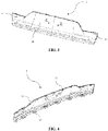
- the corresponding position of the bottom of the tailgate lower trim 3 is provided with a plurality of inner-panel connecting portions, for example, each comprising a second hole 32, as shown in FIG. 4 and FIG.
- the tailgate middle trim 2 comprises a lower-end connecting portion 21 bent inward from its lower end.
- the lower-end connecting portion 21 extends over the entire Y-direction length of the tailgate middle trim 2, so as to connect the tailgate middle trim 2 to the tailgate lower trim 3 and the tailgate inner panel 1.
- the tailgate lower trim 3 comprises an upper-end connecting portion 31 bent inward from its upper end.
- the upper-end connecting portion 31 extends over the entire Y-direction length of the tailgate lower trim 3, so as to connect the tailgate lower trim 3 to the tailgate middle trim 2.
- the upper-end connecting portion 31 of the tailgate lower trim 3 comprises a plurality of middle-trim snap-fit portions protruding inward and spaced apart from each other in the Y direction, for example, each comprising a groove 33 as shown in FIG. 4 and FIG. 9 .
- the corresponding position of the lower end of the tailgate middle trim 2 is provided with a plurality of lower-trim snap-fit portions, for example, each comprising a snap 23 as shown in FIG. 8 , such that the snap 23 mates with the groove 33 so as to connect the lower end of the tailgate middle trim 2 to the upper end of the tailgate lower trim 3.
- the Z-direction gap GV extends over the entire Y-direction length of the tailgate middle trim 2 or the tailgate lower trim 3, and thus may not remain substantially uniform along the boundary of the tailgate middle trim 2 or the tailgate lower trim 3 due to, for example, the manufacturing tolerance of the tailgate middle trim 2 or the tailgate lower trim 3. Further, it is conceivable that, since the area of the upper surface 34 of the upper-end connecting portion 31 or the area of the lower surface 24 of the lower-end connecting portion 21 is relatively large, it is difficult to improve the uniformity of the Z-direction gap GV through local adjustment.
- the tailgate assembly according to the present disclosure further comprises an adjusting/tuning component disposed on the upper-end connecting portion 31 or the lower-end connecting portion 21, so as to fill and adjust the Z-direction gap between the tailgate middle trim 2 and the tailgate lower trim 3, such that the Z-direction gap can remain substantially uniform along the boundary of the tailgate middle trim 2 or the tailgate lower trim 3.
- the adjusting component is, for example, an adjusting rib 35 that protrudes upward from the upper surface 34 of the upper-end connecting portion 31 and is preferably integrally formed with the upper-end connecting portion 31.
- the adjusting rib 35 extends over at least a part of the Y-direction length of the tailgate lower trim 3, and preferably extends over the entire Y-direction length of the tailgate lower trim 3 (that is, extends along the entire upper boundary of the tailgate lower trim 3).
- the Z-direction dimension of the adjusting rib 35 needs to be determined according to the actual dimension of the Z-direction gap. Under a normal circumstance, the Z-direction dimension of the adjusting rib 35 ranges from 0.5 mm to 2 mm. In addition, the X-direction rear edge of the adjusting rib 35 on the upper-end connecting portion 31 is spaced apart from the outer surface 36 of the tailgate lower trim 3 (that is, the outer structural boundary of the tailgate lower trim 3), for example, by an interval D1 as shown in FIG. 13 . Under a normal circumstance, the interval D1 ranges from 5 mm to 10 mm, so as to avoid easier visibility of the adjustment rib 35 from the rear side of the vehicle.
- the adjusting rib 35 does not extend continuously, but is arranged to comprise a plurality of adjusting sections.
- the plurality of adjusting sections may be evenly distributed by a same interval over the entire Y-direction length of the tailgate lower trim 3, or may be arranged at a required position according to actual need, for example, at a position adjacent to a Y-direction end of the tailgate lower trim 3.
- the adjusting component is an adjusting rib that protrudes downward from the lower surface 24 of the lower-end connecting portion 21 and is preferably integrally formed with the lower-end connecting portion 21.
- the adjusting rib extends over at least a part of the Y-direction length of the tailgate middle trim 2.
- the dimension, structure and function of the adjusting rib according to this variant are similar to those of the above-mentioned adjusting rib 35 on the upper-end connecting portion 31, thus the same descriptions will not be repeated.
- one part of the adjusting rib may be arranged on the upper surface 34 of the upper-end connecting portion 31, and another part thereof may be arranged on the lower surface 24 of the lower-end connecting portion 21.
- the shape of the position where the tailgate lower trim 3 is divided/separated from the tailgate middle trim 2 is generally not linear. More specifically, the tailgate lower trim 3 comprises two end sections 37 located at its Y-direction ends and a middle section 38 connecting the two end sections 37 and protruding upward relative to the end sections 37 in the Z direction. The top of the middle section 38 is arc-shaped.
- the adjusting rib 35 may, for example, be arranged to extend only over at least a part of the Y-direction length of the two end sections 37, preferably over the entire Y-direction length of the two end sections 37.
- the outer surface of the middle section 38 is recessed inward, for example, by a distance D2 as shown in FIG. 14 , relative to the outer surface of the end sections 37.
- This recessed structure can hide the above-mentioned corner gap GC, thereby further improving the aesthetics of the rear side of the vehicle body.
Landscapes
- Engineering & Computer Science (AREA)
- Mechanical Engineering (AREA)
- Chemical & Material Sciences (AREA)
- Combustion & Propulsion (AREA)
- Transportation (AREA)
- Vehicle Interior And Exterior Ornaments, Soundproofing, And Insulation (AREA)
Abstract
Description
- The present disclosure generally relates to the field of components for a motor vehicle, and in particular to a tailgate trim. The present disclosure further relates to a tailgate assembly comprising the tailgate trim, and a vehicle comprising the tailgate assembly.
- At present, in order to satisfy lightweight design of a vehicle body and to improve endurance of a vehicle, the use of lightweight plastic materials in more and more vehicle body structures instead of original metal materials has become a trend in the field of new energy vehicles, especially hybrid vehicles and electric vehicles. For example, a full-plastic tailgate assembly is popular with more and more vehicle manufacturers due to its excellent lightweight effect.
- The full-plastic tailgate assembly generally comprises a tailgate inner panel and a tailgate trim fixedly connected to the outer side of the tailgate inner panel by means of snap-fit, gluing, etc. The tailgate trim may comprise, for example, a tailgate middle trim on which a component such as a taillight may be mounted, and a tailgate lower trim connected to the lower end of the tailgate middle trim and on which a component such as a license plate may be mounted. It is conceivable that the tailgate lower trim needs to be repaired or replaced due to a reason such as being vulnerable to collision, thus the tailgate middle trim and the tailgate lower trim are generally designed as two independent components connected to each other.
- When viewed from the rear of the vehicle, a Z-direction gap can be seen between the tailgate middle trim and the tailgate lower trim. However, the Z-direction gap generally cannot remain substantially uniform along the boundary of the tailgate middle trim or the tailgate lower trim due to, for example, the manufacturing tolerance of the tailgate middle trim or the tailgate lower trim, and is difficult to be adjusted during the manufacturing process, thereby affecting the external aesthetics of the rear side of the vehicle body, which is not conducive to the perceived quality for user.
- An object of the present disclosure is to provide a tailgate trim to overcome the defect of the prior art in which it is difficult to remain the vertical gap between the tailgate middle trim and the tailgate lower trim uniform, thus effectively improving the aesthetics of the rear side of the vehicle body.
- To this end, a first aspect of the present disclosure provides a tailgate trim adapted to be connected to an outer side of a tailgate inner panel of a tailgate assembly and comprising at least a tailgate middle trim and a tailgate lower trim, wherein the tailgate middle trim comprises a lower-end connecting portion bent inward from a lower end of the tailgate middle trim, wherein the tailgate lower trim comprises an upper-end connecting portion bent inward from an upper end of the tailgate lower trim, and wherein the tailgate trim further comprises an adjusting component disposed on the upper-end connecting portion and/or the lower-end connecting portion and extending over at least a part of the transverse length of the tailgate trim, such that a vertical gap between the tailgate middle trim and the tailgate lower trim remains uniform.
- Optionally, the adjusting component is an adjusting rib integrally formed on the upper-end connecting portion and/or the lower-end connecting portion.
- Optionally, the adjusting component is spaced apart from an outer surface of the tailgate trim.
- Optionally, the adjusting component extends over the entire transverse length of the tailgate trim.
- Optionally, the adjusting component comprises a plurality of adjusting sections evenly distributed by a same interval over the entire transverse length of the tailgate trim.
- Optionally, the tailgate lower trim comprises two end sections located at transverse ends of the tailgate lower trim and a middle section connecting the two end sections and protruding upward relative to the end sections in the vertical direction.
- Optionally, the adjusting component extends over at least a part of the transverse length of the end sections.
- Optionally, the middle section is recessed inward relative to the end sections at a position where the tailgate lower trim is divided from the tailgate middle trim.
- A second aspect of the present disclosure provides a tailgate assembly comprising the tailgate trim according to the first aspect of the present disclosure.
- A third aspect of the present disclosure provides a vehicle comprising the tailgate assembly according to the second aspect of the present disclosure.
- Compared with the prior art, in the tailgate assembly according to the present disclosure, the vertical gap between the tailgate middle trim and the tailgate lower trim can be easily adjusted by the adjusting component disposed on the upper-end connecting portion of the tailgate lower trim and/or the lower-end connecting portion of the tailgate middle trim, so as to avoid the defect that the vertical gap is not uniform, thereby improving the aesthetics of the rear side of the vehicle body; in addition, the tailgate trim according to the present disclosure has the advantages of simple structure, convenient manufacture and low cost, thus can be widely used in various types of the tailgate assembly.
- Other features and advantages of the present disclosure will be better understood through the following preferred embodiments described in detail with reference to the accompanying drawings, in which a same reference numeral indicates a same or similar component. It is conceivable that the drawings are used not only to explain the present disclosure, but also to define the present disclosure when necessary.
-
FIG. 1 is a partial perspective view of a tailgate assembly according to an embodiment of the present disclosure; -
FIG. 2 is a perspective view of an outer side of a tailgate middle trim of the tailgate assembly inFIG. 1 ; -
FIG. 3 is a perspective view of an outer side of a tailgate lower trim of the tailgate assembly inFIG. 1 ; -
FIG. 4 is a perspective view of an inner side of the tailgate lower trim of the tailgate assembly inFIG. 1 ; -
FIG. 5 is a perspective view of an outer side of a tailgate inner panel of the tailgate assembly inFIG. 1 ; -
FIG. 6 is a schematic view for mounting the tailgate lower trim to the tailgate inner panel of the tailgate assembly inFIG. 1 ; -
FIG. 7 is a perspective view of a connecting pin adapted to the mounting structure inFIG. 6 ; -
FIG. 8 is a partial enlarged view of the tailgate middle trim of the tailgate assembly inFIG. 1 ; -
FIG. 9 is a schematic view for mounting the tailgate middle trim to the tailgate lower trim of the tailgate assembly inFIG. 1 ; -
FIG. 10 is a partial enlarged view of the tailgate lower trim of the tailgate assembly inFIG. 1 ; -
FIG. 11 is another partial enlarged view similar toFig. 10 ; -
FIG. 12 is a partial enlarged view of the tailgate assembly inFIG. 1 at a position of a vertical gap between the tailgate middle trim and the tailgate lower trim; -
FIG. 13 is another partial enlarged view similar toFig. 12 ; -
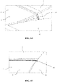
FIG. 14 is a schematic view of a recessed structure of the tailgate lower trim relative to the tailgate middle trim of the tailgate assembly inFIG. 1 ; -
FIG. 15 is a partial enlarged view of an outer side of a tailgate assembly in the prior art at a position for connecting a tailgate middle trim to a tailgate lower trim; and -
FIG. 16 is a schematic view of a gap of the connecting structure inFIG. 15 . - The implementation and usage of embodiments are discussed in detail below. However, it is conceivable that the specific embodiments discussed herein are merely intended to illustrate specific ways for implementing and using the present disclosure, and are not intended to limit the scope of the present disclosure.
- In the specification, when describing a structure or a position of a component, the directional expressions such as "upper", "lower", "left", "right", "front", and "rear" are not absolute, but relative. When the component is arranged as shown in the figures, these directional expressions are appropriate, but when the position of the component in the figures is altered, these directional expressions should be altered accordingly.
- In the specification, the X direction corresponds to the longitudinal direction of the vehicle, the Y direction corresponds to the transverse direction of the vehicle, and the Z direction corresponds to the vertical direction. In addition, "inner" and "outer" are both defined with reference to the interior and exterior of the vehicle, i.e., "inner side" refers to a side facing the interior of the vehicle, "outer side" refers to a side facing the exterior of the vehicle, "inner surface" refers to a surface facing the interior of the vehicle, and "outer surface" refers to a surface facing the exterior of the vehicle.
- As shown in
FIG. 1 to FIG. 5 , a tailgate assembly for a motor vehicle according to the present disclosure mainly comprises a tailgateinner panel 1 and a tailgate trim (also known as a tailgate outer trim) fixedly connected to the outer side of the tailgateinner panel 1. The tailgate trim comprises at least atailgate middle trim 2 and a tailgatelower trim 3. Twomounting recesses 22 for mounting left andright taillights 4 are provided at Y-direction ends of thetailgate middle trim 2, and the approximate central position of the outer side of the tailgatelower trim 3 is generally used for mounting a license plate. - More specifically, in the illustrated embodiments, the outer side of the tailgate
inner panel 1 is provided with an adhesive connection area 11 (i.e., the dark area inFIG. 5 ) corresponding to the position of the peripheral edge of thetailgate middle trim 2, which is adapted to be glued and connected to the corresponding position of the inner side of thetailgate middle trim 2. The bottom of the tailgateinner panel 1 is provided with a plurality of lower-trim connecting portions, for example, each comprising afirst hole 12, as shown inFIG. 6 , that allows a connecting pin to pass through. Accordingly, the corresponding position of the bottom of the tailgatelower trim 3 is provided with a plurality of inner-panel connecting portions, for example, each comprising asecond hole 32, as shown inFIG. 4 andFIG. 6 , that allows a same connecting pin to pass through, such that a connectingpin 5 as shown inFIG. 7 passes through thefirst hole 12 and thesecond hole 32 aligned with each other, so as to connect the bottom of the tailgateinner panel 1 to the bottom of the tailgatelower trim 3. - The lower end of the
tailgate middle trim 2 and the upper end of the tailgatelower trim 3 are connected to each other. As shown inFIG. 2 ,FIG. 8, and FIG. 9 , thetailgate middle trim 2 comprises a lower-end connecting portion 21 bent inward from its lower end. The lower-end connecting portion 21 extends over the entire Y-direction length of thetailgate middle trim 2, so as to connect thetailgate middle trim 2 to the tailgatelower trim 3 and the tailgateinner panel 1. As shown inFIG. 4 ,FIG. 8, and FIG. 9 , the tailgatelower trim 3 comprises an upper-end connecting portion 31 bent inward from its upper end. The upper-end connecting portion 31 extends over the entire Y-direction length of the tailgatelower trim 3, so as to connect the tailgatelower trim 3 to thetailgate middle trim 2. - More specifically, the upper-
end connecting portion 31 of the tailgatelower trim 3 comprises a plurality of middle-trim snap-fit portions protruding inward and spaced apart from each other in the Y direction, for example, each comprising agroove 33 as shown inFIG. 4 andFIG. 9 . Accordingly, the corresponding position of the lower end of thetailgate middle trim 2 is provided with a plurality of lower-trim snap-fit portions, for example, each comprising asnap 23 as shown inFIG. 8 , such that thesnap 23 mates with thegroove 33 so as to connect the lower end of thetailgate middle trim 2 to the upper end of the tailgatelower trim 3. - Especially referring to
FIG. 12 and FIG. 13 , after thetailgate middle trim 2 and the tailgatelower trim 3 are both connected to the tailgateinner panel 1, and thetailgate middle trim 2 is connected to the tailgatelower trim 3, an obvious Z-direction gap GV between thetailgate middle trim 2 and the tailgatelower trim 3, that is, the Z-direction gap GV between thelower surface 24 of the lower-end connecting portion 21 and theupper surface 34 of the upper-end connecting portion 31, can be seen from the rear of the vehicle. The Z-direction gap GV extends over the entire Y-direction length of thetailgate middle trim 2 or the tailgatelower trim 3, and thus may not remain substantially uniform along the boundary of thetailgate middle trim 2 or the tailgatelower trim 3 due to, for example, the manufacturing tolerance of thetailgate middle trim 2 or the tailgatelower trim 3. Further, it is conceivable that, since the area of theupper surface 34 of the upper-end connecting portion 31 or the area of thelower surface 24 of the lower-end connecting portion 21 is relatively large, it is difficult to improve the uniformity of the Z-direction gap GV through local adjustment. - In order to overcome the above-mentioned defects, the tailgate assembly according to the present disclosure further comprises an adjusting/tuning component disposed on the upper-
end connecting portion 31 or the lower-end connecting portion 21, so as to fill and adjust the Z-direction gap between the tailgatemiddle trim 2 and the tailgatelower trim 3, such that the Z-direction gap can remain substantially uniform along the boundary of the tailgatemiddle trim 2 or the tailgatelower trim 3. - As shown in
FIG. 10 to FIG. 13 , the adjusting component is, for example, an adjustingrib 35 that protrudes upward from theupper surface 34 of the upper-end connecting portion 31 and is preferably integrally formed with the upper-end connecting portion 31. The adjustingrib 35 extends over at least a part of the Y-direction length of the tailgatelower trim 3, and preferably extends over the entire Y-direction length of the tailgate lower trim 3 (that is, extends along the entire upper boundary of the tailgate lower trim 3). Therefore, when adjusting the Z-direction gap between the tailgatemiddle trim 2 and the tailgatelower trim 3, it is only necessary to change the Z-direction dimension of the adjustingrib 35 at the required position, rather than to adjust thelower surface 24 of the lower-end connecting portion 21 or theupper surface 34 of the upper-end connecting portion 31. - The Z-direction dimension of the adjusting
rib 35 needs to be determined according to the actual dimension of the Z-direction gap. Under a normal circumstance, the Z-direction dimension of the adjustingrib 35 ranges from 0.5 mm to 2 mm. In addition, the X-direction rear edge of the adjustingrib 35 on the upper-end connecting portion 31 is spaced apart from theouter surface 36 of the tailgate lower trim 3 (that is, the outer structural boundary of the tailgate lower trim 3), for example, by an interval D1 as shown inFIG. 13 . Under a normal circumstance, the interval D1 ranges from 5 mm to 10 mm, so as to avoid easier visibility of theadjustment rib 35 from the rear side of the vehicle. - According to a variant, the adjusting
rib 35 does not extend continuously, but is arranged to comprise a plurality of adjusting sections. The plurality of adjusting sections may be evenly distributed by a same interval over the entire Y-direction length of the tailgatelower trim 3, or may be arranged at a required position according to actual need, for example, at a position adjacent to a Y-direction end of the tailgatelower trim 3. - According to another variant, the adjusting component is an adjusting rib that protrudes downward from the
lower surface 24 of the lower-end connecting portion 21 and is preferably integrally formed with the lower-end connecting portion 21. The adjusting rib extends over at least a part of the Y-direction length of the tailgatemiddle trim 2. The dimension, structure and function of the adjusting rib according to this variant are similar to those of the above-mentionedadjusting rib 35 on the upper-end connecting portion 31, thus the same descriptions will not be repeated. It is also conceivable that, in case that the adjusting rib extends discontinuously, according to another variant, one part of the adjusting rib may be arranged on theupper surface 34 of the upper-end connecting portion 31, and another part thereof may be arranged on thelower surface 24 of the lower-end connecting portion 21. - As shown in
FIG. 3 andFIG. 14 toFIG. 16 , in order to increase the aesthetics of lines, the shape of the position where the tailgatelower trim 3 is divided/separated from the tailgatemiddle trim 2 is generally not linear. More specifically, the tailgatelower trim 3 comprises twoend sections 37 located at its Y-direction ends and amiddle section 38 connecting the twoend sections 37 and protruding upward relative to theend sections 37 in the Z direction. The top of themiddle section 38 is arc-shaped. In this case, the adjustingrib 35 may, for example, be arranged to extend only over at least a part of the Y-direction length of the twoend sections 37, preferably over the entire Y-direction length of the twoend sections 37. - In addition, in the tailgate assembly in the prior art shown in
FIG. 15 andFIG. 16 , at the position where the tailgatelower trim 3 is divided from the tailgatemiddle trim 2, since themiddle section 38 protrudes upward relative to theend sections 37, the upper edge of the tailgatelower trim 3 is bent at the transition position between theend sections 37 and themiddle section 38, and the lower edge of the tailgatemiddle trim 2 is also bent at the corresponding position. Since it is generally difficult to perfectly mate the tailgatemiddle trim 2 with the tailgatelower trim 3 at the above-mentioned bending position, an obvious corner gap GC can be seen at this position when viewed from the rear of the vehicle. - In the tailgate assembly according to the present disclosure, at the position where the tailgate
lower trim 3 is divided from the tailgatemiddle trim 2, the outer surface of themiddle section 38 is recessed inward, for example, by a distance D2 as shown inFIG. 14 , relative to the outer surface of theend sections 37. This recessed structure can hide the above-mentioned corner gap GC, thereby further improving the aesthetics of the rear side of the vehicle body. - The technical contents and features of the present disclosure have been disclosed above. However, it is conceivable that, those skilled in the art can make various changes and improvements to the above concept under the creative idea of the present disclosure, all of which fall within the protection scope of the present disclosure. The description to the above embodiments is exemplary rather than limitative, and the protection scope of the present disclosure is determined by the appended claims.
Claims (10)
- A tailgate trim adapted to be connected to an outer side of a tailgate inner panel (1) of a tailgate assembly and comprising at least a tailgate middle trim (2) and a tailgate lower trim (3), wherein the tailgate middle trim (2) comprises a lower-end connecting portion (21) bent inward from a lower end of the tailgate middle trim (2), wherein the tailgate lower trim (3) comprises an upper-end connecting portion (31) bent inward from an upper end of the tailgate lower trim (3), and wherein the tailgate trim further comprises an adjusting component disposed on the upper-end connecting portion (31) and/or the lower-end connecting portion (21) and extending over at least a part of the transverse length of the tailgate trim, such that a vertical gap between the tailgate middle trim (2) and the tailgate lower trim (3) remains uniform.
- The tailgate trim according to claim 1, wherein the adjusting component is an adjusting rib integrally formed on the upper-end connecting portion (31) and/or the lower-end connecting portion (21).
- The tailgate trim according to claim 1, wherein the adjusting component is spaced apart from an outer surface of the tailgate trim.
- The tailgate trim according to any one of claims 1-3, wherein the adjusting component extends over the entire transverse length of the tailgate trim.
- The tailgate trim according to any one of claims 1-3, wherein the adjusting component comprises a plurality of adjusting sections evenly distributed by a same interval over the entire transverse length of the tailgate trim.
- The tailgate trim according to any one of claims 1-3, wherein the tailgate lower trim (3) comprises two end sections (37) located at transverse ends of the tailgate lower trim (3) and a middle section (38) connecting the two end sections (37) and protruding upward relative to the end sections (37) in the vertical direction.
- The tailgate trim according to claim 6, wherein the adjusting component extends over at least a part of the transverse length of the end sections (37).
- The tailgate trim according to claim 6, wherein the middle section (38) is recessed inward relative to the end sections (37) at a position where the tailgate lower trim (3) is divided from the tailgate middle trim (2).
- A tailgate assembly comprising a tailgate inner panel (1) and the tailgate trim according to any one of claims 1-8 and connected to the tailgate inner panel (1).
- A vehicle comprising the tailgate assembly according to claim 9.
Applications Claiming Priority (1)
| Application Number | Priority Date | Filing Date | Title |
|---|---|---|---|
| CN202110359935.9A CN115179869A (en) | 2021-04-02 | 2021-04-02 | Tail door plaque, tail door assembly and vehicle |
Publications (2)
| Publication Number | Publication Date |
|---|---|
| EP4067172A1 true EP4067172A1 (en) | 2022-10-05 |
| EP4067172B1 EP4067172B1 (en) | 2024-03-13 |
Family
ID=81325499
Family Applications (1)
| Application Number | Title | Priority Date | Filing Date |
|---|---|---|---|
| EP22166035.0A Active EP4067172B1 (en) | 2021-04-02 | 2022-03-31 | Tailgate trim, tailgate assembly, and vehicle |
Country Status (2)
| Country | Link |
|---|---|
| EP (1) | EP4067172B1 (en) |
| CN (1) | CN115179869A (en) |
Cited By (1)
| Publication number | Priority date | Publication date | Assignee | Title |
|---|---|---|---|---|
| FR3144954A1 (en) * | 2023-01-17 | 2024-07-19 | Psa Automobiles Sa | TRUNK FLAP WITH ANTI-NOISE INTERFACE BETWEEN NEIGHBORHOOD PARTS, FOR A VEHICLE |
Citations (2)
| Publication number | Priority date | Publication date | Assignee | Title |
|---|---|---|---|---|
| CN209111908U (en) * | 2018-09-18 | 2019-07-16 | 上汽通用五菱汽车股份有限公司 | Split type tail-gate balustrade exterior panelling assembly, tail-gate and vehicle |
| CN209738779U (en) * | 2019-04-28 | 2019-12-06 | 江西江铃集团新能源汽车有限公司 | Automobile tail door device and automobile |
-
2021
- 2021-04-02 CN CN202110359935.9A patent/CN115179869A/en active Pending
-
2022
- 2022-03-31 EP EP22166035.0A patent/EP4067172B1/en active Active
Patent Citations (2)
| Publication number | Priority date | Publication date | Assignee | Title |
|---|---|---|---|---|
| CN209111908U (en) * | 2018-09-18 | 2019-07-16 | 上汽通用五菱汽车股份有限公司 | Split type tail-gate balustrade exterior panelling assembly, tail-gate and vehicle |
| CN209738779U (en) * | 2019-04-28 | 2019-12-06 | 江西江铃集团新能源汽车有限公司 | Automobile tail door device and automobile |
Cited By (1)
| Publication number | Priority date | Publication date | Assignee | Title |
|---|---|---|---|---|
| FR3144954A1 (en) * | 2023-01-17 | 2024-07-19 | Psa Automobiles Sa | TRUNK FLAP WITH ANTI-NOISE INTERFACE BETWEEN NEIGHBORHOOD PARTS, FOR A VEHICLE |
Also Published As
| Publication number | Publication date |
|---|---|
| EP4067172B1 (en) | 2024-03-13 |
| CN115179869A (en) | 2022-10-14 |
Similar Documents
| Publication | Publication Date | Title |
|---|---|---|
| CN102556172B (en) | Wing stay and front structure of vehicle body | |
| CN106604859B (en) | Rear spoiler for a motor vehicle | |
| WO2016147815A1 (en) | Car and car antenna device | |
| CN103085891B (en) | Vehicle splash guard | |
| JPH08310313A (en) | Pillar garnish support structure for automobile | |
| EP4067172A1 (en) | Tailgate trim, tailgate assembly, and vehicle | |
| US20090108611A1 (en) | Tailgate for vehicle | |
| CN102092355A (en) | Structural body pillar for a motor vehicle and motor vehicle having a structural body pillar | |
| US20180257597A1 (en) | Impact absorber | |
| CN203439131U (en) | C-pillar reinforcing structure | |
| US20180257596A1 (en) | Impact absorber | |
| CN103158769A (en) | Crossmember assembly for vehicles | |
| EP3408160B1 (en) | Adjustable bracket for installation of a vehicle bumper | |
| CN2913128Y (en) | Automobile rear end door | |
| CN112721592B (en) | Inner board structure of rear baffle for vehicle | |
| CN110949240B (en) | Resin back of body door tail lamp installation component and resin back of body door | |
| CN203681295U (en) | Upper supporting frame of automotive instrument panel beam | |
| CN220743178U (en) | Fender mounting structure on front cabin assembly | |
| CN212796705U (en) | Shark fin mounting structure for automobile | |
| CN221233623U (en) | Rearview mirror mounting structure and vehicle door planking | |
| CN219524038U (en) | Front cabin assembly and vehicle with same | |
| US20090212597A1 (en) | Air guiding device | |
| JP3988470B2 (en) | sunroof | |
| CN201172429Y (en) | Novel wheel guard for automobile | |
| CN210554573U (en) | Roof liner of vehicle and vehicle with same |
Legal Events
| Date | Code | Title | Description |
|---|---|---|---|
| PUAI | Public reference made under article 153(3) epc to a published international application that has entered the european phase |
Free format text: ORIGINAL CODE: 0009012 |
|
| STAA | Information on the status of an ep patent application or granted ep patent |
Free format text: STATUS: THE APPLICATION HAS BEEN PUBLISHED |
|
| AK | Designated contracting states |
Kind code of ref document: A1 Designated state(s): AL AT BE BG CH CY CZ DE DK EE ES FI FR GB GR HR HU IE IS IT LI LT LU LV MC MK MT NL NO PL PT RO RS SE SI SK SM TR |
|
| STAA | Information on the status of an ep patent application or granted ep patent |
Free format text: STATUS: REQUEST FOR EXAMINATION WAS MADE |
|
| 17P | Request for examination filed |
Effective date: 20230324 |
|
| RBV | Designated contracting states (corrected) |
Designated state(s): AL AT BE BG CH CY CZ DE DK EE ES FI FR GB GR HR HU IE IS IT LI LT LU LV MC MK MT NL NO PL PT RO RS SE SI SK SM TR |
|
| GRAP | Despatch of communication of intention to grant a patent |
Free format text: ORIGINAL CODE: EPIDOSNIGR1 |
|
| STAA | Information on the status of an ep patent application or granted ep patent |
Free format text: STATUS: GRANT OF PATENT IS INTENDED |
|
| RIC1 | Information provided on ipc code assigned before grant |
Ipc: B60J 5/10 20060101ALI20231009BHEP Ipc: B60R 13/04 20060101AFI20231009BHEP |
|
| INTG | Intention to grant announced |
Effective date: 20231106 |
|
| RAP3 | Party data changed (applicant data changed or rights of an application transferred) |
Owner name: STELLANTIS AUTO SAS |
|
| GRAS | Grant fee paid |
Free format text: ORIGINAL CODE: EPIDOSNIGR3 |
|
| GRAA | (expected) grant |
Free format text: ORIGINAL CODE: 0009210 |
|
| STAA | Information on the status of an ep patent application or granted ep patent |
Free format text: STATUS: THE PATENT HAS BEEN GRANTED |
|
| REG | Reference to a national code |
Ref country code: DE Ref legal event code: R084 Ref document number: 602022002307 Country of ref document: DE |
|
| AK | Designated contracting states |
Kind code of ref document: B1 Designated state(s): AL AT BE BG CH CY CZ DE DK EE ES FI FR GB GR HR HU IE IS IT LI LT LU LV MC MK MT NL NO PL PT RO RS SE SI SK SM TR |
|
| REG | Reference to a national code |
Ref country code: GB Ref legal event code: FG4D |
|
| REG | Reference to a national code |
Ref country code: CH Ref legal event code: EP |
|
| REG | Reference to a national code |
Ref country code: DE Ref legal event code: R096 Ref document number: 602022002307 Country of ref document: DE |
|
| REG | Reference to a national code |
Ref country code: IE Ref legal event code: FG4D |
|
| PGFP | Annual fee paid to national office [announced via postgrant information from national office to epo] |
Ref country code: DE Payment date: 20240229 Year of fee payment: 3 |
|
| REG | Reference to a national code |
Ref country code: GB Ref legal event code: 746 Effective date: 20240410 |
|
| PG25 | Lapsed in a contracting state [announced via postgrant information from national office to epo] |
Ref country code: LT Free format text: LAPSE BECAUSE OF FAILURE TO SUBMIT A TRANSLATION OF THE DESCRIPTION OR TO PAY THE FEE WITHIN THE PRESCRIBED TIME-LIMIT Effective date: 20240313 |
|
| REG | Reference to a national code |
Ref country code: LT Ref legal event code: MG9D |
|
| PG25 | Lapsed in a contracting state [announced via postgrant information from national office to epo] |
Ref country code: GR Free format text: LAPSE BECAUSE OF FAILURE TO SUBMIT A TRANSLATION OF THE DESCRIPTION OR TO PAY THE FEE WITHIN THE PRESCRIBED TIME-LIMIT Effective date: 20240614 |
|
| REG | Reference to a national code |
Ref country code: NL Ref legal event code: MP Effective date: 20240313 |
|
| PG25 | Lapsed in a contracting state [announced via postgrant information from national office to epo] |
Ref country code: HR Free format text: LAPSE BECAUSE OF FAILURE TO SUBMIT A TRANSLATION OF THE DESCRIPTION OR TO PAY THE FEE WITHIN THE PRESCRIBED TIME-LIMIT Effective date: 20240313 Ref country code: RS Free format text: LAPSE BECAUSE OF FAILURE TO SUBMIT A TRANSLATION OF THE DESCRIPTION OR TO PAY THE FEE WITHIN THE PRESCRIBED TIME-LIMIT Effective date: 20240613 |
|
| PG25 | Lapsed in a contracting state [announced via postgrant information from national office to epo] |
Ref country code: ES Free format text: LAPSE BECAUSE OF FAILURE TO SUBMIT A TRANSLATION OF THE DESCRIPTION OR TO PAY THE FEE WITHIN THE PRESCRIBED TIME-LIMIT Effective date: 20240313 |
|
| PG25 | Lapsed in a contracting state [announced via postgrant information from national office to epo] |
Ref country code: RS Free format text: LAPSE BECAUSE OF FAILURE TO SUBMIT A TRANSLATION OF THE DESCRIPTION OR TO PAY THE FEE WITHIN THE PRESCRIBED TIME-LIMIT Effective date: 20240613 Ref country code: NO Free format text: LAPSE BECAUSE OF FAILURE TO SUBMIT A TRANSLATION OF THE DESCRIPTION OR TO PAY THE FEE WITHIN THE PRESCRIBED TIME-LIMIT Effective date: 20240613 Ref country code: LT Free format text: LAPSE BECAUSE OF FAILURE TO SUBMIT A TRANSLATION OF THE DESCRIPTION OR TO PAY THE FEE WITHIN THE PRESCRIBED TIME-LIMIT Effective date: 20240313 Ref country code: HR Free format text: LAPSE BECAUSE OF FAILURE TO SUBMIT A TRANSLATION OF THE DESCRIPTION OR TO PAY THE FEE WITHIN THE PRESCRIBED TIME-LIMIT Effective date: 20240313 Ref country code: GR Free format text: LAPSE BECAUSE OF FAILURE TO SUBMIT A TRANSLATION OF THE DESCRIPTION OR TO PAY THE FEE WITHIN THE PRESCRIBED TIME-LIMIT Effective date: 20240614 Ref country code: FI Free format text: LAPSE BECAUSE OF FAILURE TO SUBMIT A TRANSLATION OF THE DESCRIPTION OR TO PAY THE FEE WITHIN THE PRESCRIBED TIME-LIMIT Effective date: 20240313 Ref country code: ES Free format text: LAPSE BECAUSE OF FAILURE TO SUBMIT A TRANSLATION OF THE DESCRIPTION OR TO PAY THE FEE WITHIN THE PRESCRIBED TIME-LIMIT Effective date: 20240313 Ref country code: BG Free format text: LAPSE BECAUSE OF FAILURE TO SUBMIT A TRANSLATION OF THE DESCRIPTION OR TO PAY THE FEE WITHIN THE PRESCRIBED TIME-LIMIT Effective date: 20240313 |
|
| PGFP | Annual fee paid to national office [announced via postgrant information from national office to epo] |
Ref country code: FR Payment date: 20240418 Year of fee payment: 3 |
|
| REG | Reference to a national code |
Ref country code: AT Ref legal event code: MK05 Ref document number: 1665474 Country of ref document: AT Kind code of ref document: T Effective date: 20240313 |
|
| PG25 | Lapsed in a contracting state [announced via postgrant information from national office to epo] |
Ref country code: SE Free format text: LAPSE BECAUSE OF FAILURE TO SUBMIT A TRANSLATION OF THE DESCRIPTION OR TO PAY THE FEE WITHIN THE PRESCRIBED TIME-LIMIT Effective date: 20240313 Ref country code: LV Free format text: LAPSE BECAUSE OF FAILURE TO SUBMIT A TRANSLATION OF THE DESCRIPTION OR TO PAY THE FEE WITHIN THE PRESCRIBED TIME-LIMIT Effective date: 20240313 |
|
| PG25 | Lapsed in a contracting state [announced via postgrant information from national office to epo] |
Ref country code: NL Free format text: LAPSE BECAUSE OF FAILURE TO SUBMIT A TRANSLATION OF THE DESCRIPTION OR TO PAY THE FEE WITHIN THE PRESCRIBED TIME-LIMIT Effective date: 20240313 |
|
| PG25 | Lapsed in a contracting state [announced via postgrant information from national office to epo] |
Ref country code: NL Free format text: LAPSE BECAUSE OF FAILURE TO SUBMIT A TRANSLATION OF THE DESCRIPTION OR TO PAY THE FEE WITHIN THE PRESCRIBED TIME-LIMIT Effective date: 20240313 |
|
| PG25 | Lapsed in a contracting state [announced via postgrant information from national office to epo] |
Ref country code: IS Free format text: LAPSE BECAUSE OF FAILURE TO SUBMIT A TRANSLATION OF THE DESCRIPTION OR TO PAY THE FEE WITHIN THE PRESCRIBED TIME-LIMIT Effective date: 20240713 |