EP4070968A1 - Motorcycle tyre - Google Patents
Motorcycle tyre Download PDFInfo
- Publication number
- EP4070968A1 EP4070968A1 EP22160057.0A EP22160057A EP4070968A1 EP 4070968 A1 EP4070968 A1 EP 4070968A1 EP 22160057 A EP22160057 A EP 22160057A EP 4070968 A1 EP4070968 A1 EP 4070968A1
- Authority
- EP
- European Patent Office
- Prior art keywords
- tyre
- tan
- rubber layer
- base rubber
- tread
- Prior art date
- Legal status (The legal status is an assumption and is not a legal conclusion. Google has not performed a legal analysis and makes no representation as to the accuracy of the status listed.)
- Granted
Links
Images

Classifications
-
- B—PERFORMING OPERATIONS; TRANSPORTING
- B60—VEHICLES IN GENERAL
- B60C—VEHICLE TYRES; TYRE INFLATION; TYRE CHANGING; CONNECTING VALVES TO INFLATABLE ELASTIC BODIES IN GENERAL; DEVICES OR ARRANGEMENTS RELATED TO TYRES
- B60C11/00—Tyre tread bands; Tread patterns; Anti-skid inserts
- B60C11/0041—Tyre tread bands; Tread patterns; Anti-skid inserts comprising different tread rubber layers
- B60C11/005—Tyre tread bands; Tread patterns; Anti-skid inserts comprising different tread rubber layers with cap and base layers
- B60C11/0058—Tyre tread bands; Tread patterns; Anti-skid inserts comprising different tread rubber layers with cap and base layers with different cap rubber layers in the axial direction
-
- B—PERFORMING OPERATIONS; TRANSPORTING
- B60—VEHICLES IN GENERAL
- B60C—VEHICLE TYRES; TYRE INFLATION; TYRE CHANGING; CONNECTING VALVES TO INFLATABLE ELASTIC BODIES IN GENERAL; DEVICES OR ARRANGEMENTS RELATED TO TYRES
- B60C11/00—Tyre tread bands; Tread patterns; Anti-skid inserts
- B60C11/0041—Tyre tread bands; Tread patterns; Anti-skid inserts comprising different tread rubber layers
- B60C11/005—Tyre tread bands; Tread patterns; Anti-skid inserts comprising different tread rubber layers with cap and base layers
-
- B—PERFORMING OPERATIONS; TRANSPORTING
- B60—VEHICLES IN GENERAL
- B60C—VEHICLE TYRES; TYRE INFLATION; TYRE CHANGING; CONNECTING VALVES TO INFLATABLE ELASTIC BODIES IN GENERAL; DEVICES OR ARRANGEMENTS RELATED TO TYRES
- B60C11/00—Tyre tread bands; Tread patterns; Anti-skid inserts
- B60C11/0008—Tyre tread bands; Tread patterns; Anti-skid inserts characterised by the tread rubber
- B60C2011/0016—Physical properties or dimensions
- B60C2011/0025—Modulus or tan delta
-
- B—PERFORMING OPERATIONS; TRANSPORTING
- B60—VEHICLES IN GENERAL
- B60C—VEHICLE TYRES; TYRE INFLATION; TYRE CHANGING; CONNECTING VALVES TO INFLATABLE ELASTIC BODIES IN GENERAL; DEVICES OR ARRANGEMENTS RELATED TO TYRES
- B60C11/00—Tyre tread bands; Tread patterns; Anti-skid inserts
- B60C11/0008—Tyre tread bands; Tread patterns; Anti-skid inserts characterised by the tread rubber
- B60C2011/0016—Physical properties or dimensions
- B60C2011/0033—Thickness of the tread
-
- B—PERFORMING OPERATIONS; TRANSPORTING
- B60—VEHICLES IN GENERAL
- B60C—VEHICLE TYRES; TYRE INFLATION; TYRE CHANGING; CONNECTING VALVES TO INFLATABLE ELASTIC BODIES IN GENERAL; DEVICES OR ARRANGEMENTS RELATED TO TYRES
- B60C11/00—Tyre tread bands; Tread patterns; Anti-skid inserts
- B60C11/03—Tread patterns
- B60C2011/0337—Tread patterns characterised by particular design features of the pattern
- B60C2011/0339—Grooves
-
- B—PERFORMING OPERATIONS; TRANSPORTING
- B60—VEHICLES IN GENERAL
- B60C—VEHICLE TYRES; TYRE INFLATION; TYRE CHANGING; CONNECTING VALVES TO INFLATABLE ELASTIC BODIES IN GENERAL; DEVICES OR ARRANGEMENTS RELATED TO TYRES
- B60C2200/00—Tyres specially adapted for particular applications
- B60C2200/10—Tyres specially adapted for particular applications for motorcycles, scooters or the like
-
- Y—GENERAL TAGGING OF NEW TECHNOLOGICAL DEVELOPMENTS; GENERAL TAGGING OF CROSS-SECTIONAL TECHNOLOGIES SPANNING OVER SEVERAL SECTIONS OF THE IPC; TECHNICAL SUBJECTS COVERED BY FORMER USPC CROSS-REFERENCE ART COLLECTIONS [XRACs] AND DIGESTS
- Y02—TECHNOLOGIES OR APPLICATIONS FOR MITIGATION OR ADAPTATION AGAINST CLIMATE CHANGE
- Y02T—CLIMATE CHANGE MITIGATION TECHNOLOGIES RELATED TO TRANSPORTATION
- Y02T10/00—Road transport of goods or passengers
- Y02T10/80—Technologies aiming to reduce greenhouse gasses emissions common to all road transportation technologies
- Y02T10/86—Optimisation of rolling resistance, e.g. weight reduction
Definitions
- the present disclosure relates to a motorcycle tyre.
- Patent Document 1 discloses a motorcycle tyre having a tread rubber which includes a base rubber layer and a pair of shoulder rubber layers made of a rubber composition with a larger amount of oil component than that of the base rubber layer.
- the motorcycle tyre can be expected to exhibit excellent durability and steering stability.
- Patent document 1 Japanese Unexamined Patent Application Publication 2018-76002
- the present disclosure has been made in view of the above circumstances and has a major object to provide a motorcycle tyre capable of improving grip performance during turning while maintaining wear resistance during straight running.
- a motorcycle tyre includes a tread portion with a ground contact surface, the tread portion including a tread rubber including a base rubber layer and a cap rubber layer disposed outward in a tyre radial direction of the base rubber layer to form the ground contact surface of the tread portion, the cap rubber layer including a crown cap portion disposed in a middle region in a tyre axial direction of the tread portion and a pair of shoulder cap portions disposed in both sides in the tyre axial direction of the crown cap portion, and the crown cap portion having a loss tangent tan ⁇ c at 0 degrees C., the shoulder cap portions having a loss tangent tan ⁇ s at 0 degrees C., and the base rubber layer having a loss tangent tan ⁇ b at 0 degrees C., wherein the loss tangents tan ⁇ c, tan ⁇ s and tan ⁇ b satisfy the following equation (1): tan ⁇ c ⁇
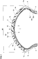
- FIG.1 is a cross-sectional view including a tyre axis of an embodiment of a motorcycle tyre 1 (hereafter, simply referred to as "tyre") in accordance with the present disclosure.
- tyre a motorcycle tyre 1
- the tyre 1 according to the present embodiment is a tyre for rear wheel of motorcycle suitable for sports driving on the road.
- the tyre according to the present invention is not limited to such an embodiment.
- the "normal state" is such that the tyre 1 is mounted onto a standard wheel rim with a standard pressure but loaded with no tyre load. If a tyre is not based on the standards, the normal state is a standard state of use according to the purpose of use of the tyre and means a state of no load. As used herein, unless otherwise noted, dimensions of portions of the tyre are values measured under the normal state.
- the "standard wheel rim” is a wheel rim officially approved for each tyre by standards organizations on which the tyre is based, wherein the standard wheel rim is the "standard rim” specified in JATMA, the "Design Rim” in TRA, and the “Measuring Rim” in ETRTO, for example.
- the "standard pressure” is a standard pressure officially approved for each tyre by standards organizations on which the tyre is based, wherein the standard pressure is the "maximum air pressure” in JATMA, the maximum pressure given in the "Tire Load Limits at Various Cold Inflation Pressures” table in TRA, and the “Inflation Pressure” in ETRTO, for example.
- the tyre 1 includes a tread portion 2, a pair of sidewall portions 3, and a pair of bead portions 4.
- the pair of sidewall portions 3 is connected to both ends in the tyre axial direction of the tread portion 2.
- the pair of bead portions 4 is connected to inner ends of the pair of sidewall portions 3.
- the tread portion 2 includes a ground contact surface 2a between tread edges Te and Te.
- the ground contact surface 2a is curved in an arc shape manner to be convex outward in the tyre radial direction to obtain a sufficient ground contact area even when turning with large camber angles.
- the pair of tread edges Te is located outermost in the tyre axial direction.
- the tyre 1 includes a carcass 6 which extends between the pair of bead portions 4 through the tread portion 2 and the pair of sidewall portions 3.
- the carcass 6, for example, includes at least one carcass ply 6A with a plurality of carcass cords.
- Each of the carcass plies 6A includes a main portion 6a and a pair of turn-up portions 6b.
- the main portion 6a extends between the pair of bead portions 4 through the tread portion 2 and the pair of sidewall portions 3.
- the turn-up portions 6b are turned up around respective bead cores 5 of the bead portions 4 from axially inside to outside of the tyre.
- a belt layer 7 is provided in the tread portion 2, for example.
- the belt layer 7, for example, includes at least one belt ply having a plurality of belt cords oriented at an angle of 10 to 45 degrees with respect to the tyre circumferential direction.
- the belt layer 7 according to the present embodiment consist of a single belt ply. Alternatively, a plurality of belt plies which is superimposed may be employed. Such a belt layer 7 can enhance the tread portion 2 effectively.
- FIG. 2 illustrates an enlarged view of the tread portion 2 of FIG. 1 .
- the tread portion 2 includes a tread rubber 2G disposed outward in the tyre radial direction of the carcass 6 and the belt layer 7.
- the tread rubber 2G of the tread portion 2 includes a base rubber layer 10 and a cap rubber layer 11 disposed outward in the tyre radial direction of the base rubber layer 10 to form the ground contact surface 2a of the tread portion 2.
- the cap rubber layer 11 includes a crown cap portion 12 disposed in a middle region in the tyre axial direction of the tread portion 2 and a pair of shoulder cap portions 13 disposed in both sides in the tyre axial direction of the crown cap portion 12.
- the crown cap portion 12 has a loss tangent tan ⁇ c at 0 degrees C.
- the shoulder cap portions 13 has a loss tangent tan ⁇ s at 0 degrees C.
- the base rubber layer 10 has a loss tangent tan ⁇ b at 0 degrees C.
- the loss tangents tan ⁇ c, tan ⁇ s and tan ⁇ b satisfy the following equation (1): tan ⁇ c ⁇ tan ⁇ s ⁇ tan ⁇ b .
- loss tangent tan ⁇ is a value measured using a “viscoelastic spectrometer” manufactured by Iwamoto Seisakusho Co., Ltd. under the following conditions in accordance with the provisions of JIS-K6394.
- the crown cap portion 12 which comes into contact with the ground when straight running, can have relatively low heat generation and can maintain its wear resistance.
- the shoulder cap portions 13, which come into contact with the ground during turning can generate moderate heat due to the deformation of the tread rubber 2G, and can exhibit excellent grip performance during turning.
- the loss tangent tan ⁇ b of the base rubber layer 10 is equal to or more than the loss tangent tan ⁇ s of the shoulder cap portions 13, high heat generation can be expected with the base rubber layer 10.
- the heat generation of the base rubber layer 10 can be small, and the wear resistance performance during straight running can be maintained.
- the base rubber layer 10 can generate heat moderately, and the grip force of the shoulder cap portions 13 can be further enhanced. It is presumed that the present disclosure can improve the grip performance during turning while maintaining the wear resistance performance during straight running due to such a mechanism.
- each configuration described below shows a specific aspect of the present embodiment.
- the present disclosure can exert the above-mentioned effects even if the tyre does not include the configuration described below.
- the performance improvement according to each additional configuration can be expected.
- the loss tangent tan ⁇ c of the crown cap portion 12 (hereafter, it may be simply referred to as "tan ⁇ c”.), the loss tangent tan ⁇ s of the shoulder cap portions 13 (hereafter, it may be simply referred to as “tan ⁇ s”.), and the loss tangent tan ⁇ b of the base rubber layer 10 (hereafter, it may be simply referred to as "tan ⁇ b”.), for example, are in a range from 0.20 to 1.60.
- the tan ⁇ c for example, is preferably in a range from 0.20 to 0.90, more preferably in a range from 0.70 to 0.90.
- the tan ⁇ s for example, is preferably in a range from 0.80 to 1.40, more preferably in a range from 0.90 to 1.10.
- the tan ⁇ b for example, is preferably in a range from 0.80 to 1.60, more preferably in a range from 1.00 to 1.20.
- the tan ⁇ s for example, is in a range from 105% to 140% of the tan ⁇ c, preferably from 105% to 120%.
- the tan ⁇ b is greater than the tan ⁇ s.
- the tan ⁇ b is more preferably in a range from 100% to 140% of the tan ⁇ s, still further preferably from 105% to 120%.
- a JIS-A hardness of the shoulder cap portions 13 is in a range of -2 to +5 degrees with respect to a JIS-A hardness of the crown cap portion 12.
- transient characteristic of the response when tilting a vehicle body of a motorcycle can be improved, and uneven wear around the boundary between the crown cap portion 12 and the respective shoulder cap portions 13 can be suppressed while exerting the above-mentioned effects.
- JIS-A hardness means a hardness of rubber at 25 degrees C. measured by durometer type A based on JIS-K6253.
- a JIS-A hardness of the base rubber layer 10 is preferably in a range of -2 to +5 degrees with respect to a JIS-A hardness of the shoulder cap portions 13. This can prevent the separation between the base rubber layer 10 and the respective shoulder cap portions 13 during turning.
- the rubber layers having the above-mentioned characteristics can be obtained by appropriately combining known materials used in rubber production.
- a thickness of the base rubber layer 10 located inward in the tyre radial direction of the shoulder cap portions 13 is larger than a thickness of the base rubber layer 10 located inward in the tyre radial direction of the crown cap portion 12.
- Such a base rubber layer 10 can surely improve the grip performance during turning while maintaining the wear resistance performance during straight running.
- a thickness of the base rubber layer 10 may increase continuously from a middle region in the tyre axial direction thereof toward both ends in the tyre axial direction thereof.
- a thickness t2 of the base rubber layer 10 at the center position of the ground contact surface of each shoulder cap portion 13 is preferably equal to or more than 1.5 times a thickness t1 of the base rubber layer 10 on the tyre equator C, more preferably equal to or more than 1.8 times, but preferably equal to or less than 2.5 times the thickness t1, more preferably equal to or less than 2.2 times. This can help to improve the wear resistance during straight running and the grip performance during turning in a well-balanced manner.
- a thickness of the base rubber layer 10 is preferably equal to or more than 10%, more preferably in a range from 10% to 40% of a total thickness of the tread rubber 2G.
- the total thickness of the tread rubber 2G is a thickness from the ground contact surface to an outer surface 2a of the belt layer 7.
- the minimum thickness of the base rubber layer 10 is preferably in a range from 10% to 20% of the total thickness of the tread rubber 2G. This can help to maintain uneven wear resistance of the crown cap portion 12.
- the maximum width W2 in the tyre axial direction of the ground contact surface of the crown cap portion 12 is in a range from 20% to 60% of the maximum width W1 (shown in FIG. 1 ) of the ground contact surface of the tread portion 2, more preferably from 20% to 40%.
- uneven wear resistance can be reliably maintained when straight running and when turning at relatively small camber angles.
- the tread rubber 2G consists only of the base rubber layer 10 and the cap rubber layer 11 as mentioned above, and no other rubber components are disposed.
- the above effects can surely be exhibited.
- the present disclosure is not limited to such an aspect.
- the ground contact surface 2a of the tread portion 2 may be provided with a plurality of grooves 15.
- a depth of the grooves 15 is smaller than the thickness of the cap rubber layer 11.
- the base rubber layer 10 is not exposed at a surface of the grooves 15. As a result, the base rubber layer 10 is not exposed even if the tread portion 2 wear progresses, and excellent wear resistance and steering stability can continuously be exhibited.
- motorcycle tyres (size: 180/55R17) for rear wheel tyre with the basic structure shown in FIG. 1 were prepared based on the specifications in Tables 1 to 2.
- a tyre with a single crown rubber was also prepared.
- the tyre of the comparative example has substantially the same configuration as the tyre of the examples except for the above feature.
- the wear resistance performance during straight running, the grip performance during straight running, the grip performance during turning, and the steering stability of the test tyres were tested.
- the common specifications and test methods for each test tyre are as follows.
- Test for wear resistance when straight running The remaining rubber thickness at the center of the tread portion was measured after traveling 10,000 km on a general road with the above test tyre. The test results are shown in Tables using an index with the remaining rubber thickness of the comparative example as 100. The larger the value, the larger the remaining rubber thickness and the better the wear resistance.
- Test for grip performance when driving straight, grip performance when turning and turning stability The grip performance when driving straight, the grip performance when turning, and the turning stability when driving on a circuit with the above test tyres were evaluated by the driver's sensuality. The test results are shown in Tables using a score with a comparative example of 100, and the larger the value, the better.
- Tables 1 and 2 show the test results. [Table 1] Ref. Ex. 1 Ex. 2 Ex. 3 Ex. 4 Ex. 5 Ex. 6 Ex. 7 Loss tangent tan ⁇ c of crown cap portion 0.80 0.80 0.72 0.76 0.84 0.88 0.80 0.80 Loss tangent tan ⁇ s of shoulder cap portions 0.80 1.00 1.00 1.00 1.00 0.90 0.95 Loss tangent tan ⁇ b of base rubber layer 0.80 1.10 1.10 1.10 1.10 1.10 1.10 1.10 1.10 Wear resistance during straight running (index) 100 100 104 102 100 98 100 100 Grip performance during straight running (score) 100 110 104 107 112 114 100 100 Grip performance during turning (score) 100 115 115 115 115 110 113 Turning stability (scire) 100 120 119 120 121 122 116 118 [Table 2] Ex.
- a motorcycle tyre comprising:
- a maximum width in the tyre axial direction of the crown cap portion at the ground contact surface is in a range from 20% to 60% of a maximum width in the tyre axial direction of the ground contact surface of the tread portion.
- a thickness of the base rubber layer is in a range from 10% to 40% of a total thickness of the tread rubber.
Landscapes
- Engineering & Computer Science (AREA)
- Mechanical Engineering (AREA)
- Tires In General (AREA)
Abstract
Description
- This application claims the benefit of foreign priority to Japanese Patent Application No.
JP2021-066059, filed April 8, 2021 - The present disclosure relates to a motorcycle tyre.
- Conventionally, various motorcycle tyres having improved tread rubber have been proposed. For example, Patent Document 1 below discloses a motorcycle tyre having a tread rubber which includes a base rubber layer and a pair of shoulder rubber layers made of a rubber composition with a larger amount of oil component than that of the base rubber layer. The motorcycle tyre can be expected to exhibit excellent durability and steering stability.
- [Patent document 1]
Japanese Unexamined Patent Application Publication 2018-76002 - Recent years, with the increasing performance of motorcycles, there has been a demand for motorcycle tyres with excellent grip performance during turning. On the other hand, in motorcycle tyres, when the grip performance is improved, the wear resistance during straight running may be impaired.
- The present disclosure has been made in view of the above circumstances and has a major object to provide a motorcycle tyre capable of improving grip performance during turning while maintaining wear resistance during straight running.
- In one aspect of the present disclosure, a motorcycle tyre includes a tread portion with a ground contact surface, the tread portion including a tread rubber including a base rubber layer and a cap rubber layer disposed outward in a tyre radial direction of the base rubber layer to form the ground contact surface of the tread portion, the cap rubber layer including a crown cap portion disposed in a middle region in a tyre axial direction of the tread portion and a pair of shoulder cap portions disposed in both sides in the tyre axial direction of the crown cap portion, and the crown cap portion having a loss tangent tan δc at 0 degrees C., the shoulder cap portions having a loss tangent tan δs at 0 degrees C., and the base rubber layer having a loss tangent tan δb at 0 degrees C., wherein the loss tangents tan δc, tan δs and tan δb satisfy the following equation (1):

-
-
FIG. 1 is a cross-sectional view of an embodiment of a motorcycle tyre in accordance with the present disclosure; and -
FIG. 2 is an enlarged view of a tread portion ofFIG. 1 . - Hereinafter, one or more embodiments of the present disclosure will be described with reference to the drawings.
FIG.1 is a cross-sectional view including a tyre axis of an embodiment of a motorcycle tyre 1 (hereafter, simply referred to as "tyre") in accordance with the present disclosure. Note that inFIG. 1 the tyre 1 is under a normal state. The tyre 1 according to the present embodiment is a tyre for rear wheel of motorcycle suitable for sports driving on the road. However, the tyre according to the present invention is not limited to such an embodiment. - As used herein, when a tyre is a pneumatic tyre based on a standard, the "normal state" is such that the tyre 1 is mounted onto a standard wheel rim with a standard pressure but loaded with no tyre load. If a tyre is not based on the standards, the normal state is a standard state of use according to the purpose of use of the tyre and means a state of no load. As used herein, unless otherwise noted, dimensions of portions of the tyre are values measured under the normal state.
- As used herein, the "standard wheel rim" is a wheel rim officially approved for each tyre by standards organizations on which the tyre is based, wherein the standard wheel rim is the "standard rim" specified in JATMA, the "Design Rim" in TRA, and the "Measuring Rim" in ETRTO, for example.
- As used herein, the "standard pressure" is a standard pressure officially approved for each tyre by standards organizations on which the tyre is based, wherein the standard pressure is the "maximum air pressure" in JATMA, the maximum pressure given in the "Tire Load Limits at Various Cold Inflation Pressures" table in TRA, and the "Inflation Pressure" in ETRTO, for example.
- As illustrated in
FIG. 1 , the tyre 1 according to the present embodiment includes atread portion 2, a pair ofsidewall portions 3, and a pair ofbead portions 4. The pair ofsidewall portions 3 is connected to both ends in the tyre axial direction of thetread portion 2. The pair ofbead portions 4 is connected to inner ends of the pair ofsidewall portions 3. Thetread portion 2 includes aground contact surface 2a between tread edges Te and Te. Theground contact surface 2a is curved in an arc shape manner to be convex outward in the tyre radial direction to obtain a sufficient ground contact area even when turning with large camber angles. In the present embodiment, the pair of tread edges Te is located outermost in the tyre axial direction. - The tyre 1 according to the present embodiment includes a
carcass 6 which extends between the pair ofbead portions 4 through thetread portion 2 and the pair ofsidewall portions 3. - The
carcass 6, for example, includes at least onecarcass ply 6A with a plurality of carcass cords. In the present embodiment, thecarcass 6, for example, includes twocarcass plies 6A. Each of thecarcass plies 6A includes amain portion 6a and a pair of turn-upportions 6b. Themain portion 6a extends between the pair ofbead portions 4 through thetread portion 2 and the pair ofsidewall portions 3. The turn-upportions 6b are turned up around respective bead cores 5 of thebead portions 4 from axially inside to outside of the tyre. - A
belt layer 7 is provided in thetread portion 2, for example. Thebelt layer 7, for example, includes at least one belt ply having a plurality of belt cords oriented at an angle of 10 to 45 degrees with respect to the tyre circumferential direction. Thebelt layer 7 according to the present embodiment consist of a single belt ply. Alternatively, a plurality of belt plies which is superimposed may be employed. Such abelt layer 7 can enhance thetread portion 2 effectively. -
FIG. 2 illustrates an enlarged view of thetread portion 2 ofFIG. 1 . As illustrated inFIG. 2 , thetread portion 2 includes atread rubber 2G disposed outward in the tyre radial direction of thecarcass 6 and thebelt layer 7. Thetread rubber 2G of thetread portion 2 includes abase rubber layer 10 and acap rubber layer 11 disposed outward in the tyre radial direction of thebase rubber layer 10 to form theground contact surface 2a of thetread portion 2. - The
cap rubber layer 11 includes acrown cap portion 12 disposed in a middle region in the tyre axial direction of thetread portion 2 and a pair ofshoulder cap portions 13 disposed in both sides in the tyre axial direction of thecrown cap portion 12. - In the present disclosure, the
crown cap portion 12 has a loss tangent tan δc at 0 degrees C., theshoulder cap portions 13 has a loss tangent tan δs at 0 degrees C., and thebase rubber layer 10 has a loss tangent tan δb at 0 degrees C., wherein the loss tangents tan δc, tan δs and tan δb satisfy the following equation (1):
- As used herein, "loss tangent tan δ" is a value measured using a "viscoelastic spectrometer" manufactured by Iwamoto Seisakusho Co., Ltd. under the following conditions in accordance with the provisions of JIS-K6394.
- Initial strain: 10%
- Amplitude of dynamic strain: +-1%
- Frequency: 10 Hz
- Deformation mode: tension
- Measurement temperature: 0 degrees C.
- In the present disclosure, by adopting the above-mentioned configuration, it is possible to improve the grip performance during turning while maintaining the wear resistance performance during straight running. The reason for this is presumed to be the following mechanism.
- In the present embodiment, since the loss tangent tan δs of the
shoulder cap portions 13 is greater than the loss tangent tan δc of thecrown cap portion 12, thecrown cap portion 12, which comes into contact with the ground when straight running, can have relatively low heat generation and can maintain its wear resistance. On the other hand, theshoulder cap portions 13, which come into contact with the ground during turning, can generate moderate heat due to the deformation of thetread rubber 2G, and can exhibit excellent grip performance during turning. - Further, in the present disclosure, since the loss tangent tan δb of the
base rubber layer 10 is equal to or more than the loss tangent tan δs of theshoulder cap portions 13, high heat generation can be expected with thebase rubber layer 10. Thus, during straight running when thecrown cap portion 12 comes into contact with the ground as well as during turning at relatively small camber angles, since an amount of deformation of thetread rubber 2G tends to be small, the heat generation of thebase rubber layer 10 can be small, and the wear resistance performance during straight running can be maintained. Furthermore, during turning where theshoulder cap portions 13 come into contact with the ground, since thetread rubber 2G has a large amount of deformation, thebase rubber layer 10 can generate heat moderately, and the grip force of theshoulder cap portions 13 can be further enhanced. It is presumed that the present disclosure can improve the grip performance during turning while maintaining the wear resistance performance during straight running due to such a mechanism. - Hereinafter, a more detailed configuration of the present embodiment will be described. Note that each configuration described below shows a specific aspect of the present embodiment. Thus, the present disclosure can exert the above-mentioned effects even if the tyre does not include the configuration described below. Further, if any one of the configurations described below is applied independently to the tyre of the present disclosure having the above-mentioned characteristics, the performance improvement according to each additional configuration can be expected. Furthermore, when some of the configurations described below are applied in combination, it is expected that the performance of the additional configurations will be improved.
- In the present embodiment, the loss tangent tan δc of the crown cap portion 12 (hereafter, it may be simply referred to as "tan δc".), the loss tangent tan δs of the shoulder cap portions 13 (hereafter, it may be simply referred to as "tan δs".), and the loss tangent tan δb of the base rubber layer 10 (hereafter, it may be simply referred to as "tan δb".), for example, are in a range from 0.20 to 1.60. Specifically, the tan δc, for example, is preferably in a range from 0.20 to 0.90, more preferably in a range from 0.70 to 0.90. The tan δs, for example, is preferably in a range from 0.80 to 1.40, more preferably in a range from 0.90 to 1.10. The tan δb, for example, is preferably in a range from 0.80 to 1.60, more preferably in a range from 1.00 to 1.20.
- Further, the tan δs, for example, is in a range from 105% to 140% of the tan δc, preferably from 105% to 120%. Preferably, the tan δb is greater than the tan δs. The tan δb is more preferably in a range from 100% to 140% of the tan δs, still further preferably from 105% to 120%. As a result, damage such as separation of the rubber layers can be suppressed while exerting the above-mentioned effects.
- Preferably, a JIS-A hardness of the
shoulder cap portions 13 is in a range of -2 to +5 degrees with respect to a JIS-A hardness of thecrown cap portion 12. Thus, transient characteristic of the response when tilting a vehicle body of a motorcycle can be improved, and uneven wear around the boundary between thecrown cap portion 12 and the respectiveshoulder cap portions 13 can be suppressed while exerting the above-mentioned effects. - As used herein, "JIS-A hardness" means a hardness of rubber at 25 degrees C. measured by durometer type A based on JIS-K6253.
- Similarly, a JIS-A hardness of the
base rubber layer 10 is preferably in a range of -2 to +5 degrees with respect to a JIS-A hardness of theshoulder cap portions 13. This can prevent the separation between thebase rubber layer 10 and the respectiveshoulder cap portions 13 during turning. - Note that the rubber layers having the above-mentioned characteristics can be obtained by appropriately combining known materials used in rubber production.
- Preferably, a thickness of the
base rubber layer 10 located inward in the tyre radial direction of theshoulder cap portions 13 is larger than a thickness of thebase rubber layer 10 located inward in the tyre radial direction of thecrown cap portion 12. Such abase rubber layer 10 can surely improve the grip performance during turning while maintaining the wear resistance performance during straight running. - In some more preferred embodiments, a thickness of the
base rubber layer 10 may increase continuously from a middle region in the tyre axial direction thereof toward both ends in the tyre axial direction thereof. With this, the transient characteristic when tilting a vehicle body of a motorcycle can be improved. - A thickness t2 of the
base rubber layer 10 at the center position of the ground contact surface of each shoulder cap portion 13 (the center position in the length direction of the ground contact surface of eachcap portion 13 in a tyre cross section) is preferably equal to or more than 1.5 times a thickness t1 of thebase rubber layer 10 on the tyre equator C, more preferably equal to or more than 1.8 times, but preferably equal to or less than 2.5 times the thickness t1, more preferably equal to or less than 2.2 times. This can help to improve the wear resistance during straight running and the grip performance during turning in a well-balanced manner. - In a region of inward in the tyre radial direction of the
crown cap portion 12, a thickness of thebase rubber layer 10 is preferably equal to or more than 10%, more preferably in a range from 10% to 40% of a total thickness of thetread rubber 2G. Note that the total thickness of thetread rubber 2G is a thickness from the ground contact surface to anouter surface 2a of thebelt layer 7. Further, in a region of inward in the tyre radial direction of thecrown cap portion 12, the minimum thickness of the base rubber layer 10 (in this embodiment, the thickness t1 on the tyre equator C) is preferably in a range from 10% to 20% of the total thickness of thetread rubber 2G. This can help to maintain uneven wear resistance of thecrown cap portion 12. - Preferably, the maximum width W2 in the tyre axial direction of the ground contact surface of the
crown cap portion 12 is in a range from 20% to 60% of the maximum width W1 (shown inFIG. 1 ) of the ground contact surface of thetread portion 2, more preferably from 20% to 40%. Thus, uneven wear resistance can be reliably maintained when straight running and when turning at relatively small camber angles. - In the present embodiment, the
tread rubber 2G consists only of thebase rubber layer 10 and thecap rubber layer 11 as mentioned above, and no other rubber components are disposed. Thus, the above effects can surely be exhibited. However, the present disclosure is not limited to such an aspect. - The
ground contact surface 2a of thetread portion 2 may be provided with a plurality ofgrooves 15. In this case, it is preferable that a depth of thegrooves 15 is smaller than the thickness of thecap rubber layer 11. In other words, it is preferable that thebase rubber layer 10 is not exposed at a surface of thegrooves 15. As a result, thebase rubber layer 10 is not exposed even if thetread portion 2 wear progresses, and excellent wear resistance and steering stability can continuously be exhibited. - While the particularly preferable embodiments of the motorcycle tyre in accordance with the present disclosure have been described in detail, the present disclosure is not limited to the illustrated embodiments, but can be modified and carried out in various aspects within the scope of the disclosure.
- Motorcycle tyres (size: 180/55R17) for rear wheel tyre with the basic structure shown in
FIG. 1 were prepared based on the specifications in Tables 1 to 2. As a comparative example, a tyre with a single crown rubber was also prepared. The tyre of the comparative example has substantially the same configuration as the tyre of the examples except for the above feature. The wear resistance performance during straight running, the grip performance during straight running, the grip performance during turning, and the steering stability of the test tyres were tested. The common specifications and test methods for each test tyre are as follows. - Rim size: MT5.50
- Tyre inner pressure: 250 kPa
- Test vehicle displacement: 1000 cc
- Test for wear resistance when straight running:
The remaining rubber thickness at the center of the tread portion was measured after traveling 10,000 km on a general road with the above test tyre. The test results are shown in Tables using an index with the remaining rubber thickness of the comparative example as 100. The larger the value, the larger the remaining rubber thickness and the better the wear resistance. - Test for grip performance when driving straight, grip performance when turning and turning stability:
The grip performance when driving straight, the grip performance when turning, and the turning stability when driving on a circuit with the above test tyres were evaluated by the driver's sensuality. The test results are shown in Tables using a score with a comparative example of 100, and the larger the value, the better. - Tables 1 and 2 show the test results.
[Table 1] Ref. Ex. 1 Ex. 2 Ex. 3 Ex. 4 Ex. 5 Ex. 6 Ex. 7 Loss tangent tan δc of crown cap portion 0.80 0.80 0.72 0.76 0.84 0.88 0.80 0.80 Loss tangent tan δs of shoulder cap portions 0.80 1.00 1.00 1.00 1.00 1.00 0.90 0.95 Loss tangent tan δb of base rubber layer 0.80 1.10 1.10 1.10 1.10 1.10 1.10 1.10 Wear resistance during straight running (index) 100 100 104 102 100 98 100 100 Grip performance during straight running (score) 100 110 104 107 112 114 100 100 Grip performance during turning (score) 100 115 115 115 115 115 110 113 Turning stability (scire) 100 120 119 120 121 122 116 118 [Table 2] Ex. 8 Ex. 9 Ex. 10 Ex. 11 Ex. 12 Ex. 13 Loss tangent tan δc of crown cap portion 0.80 0.80 0.80 0.80 0.80 0.80 Loss tangent tan δs of shoulder cap portions 1.05 1.10 1.00 1.00 1.00 1.00 Loss tangent tan δb of base rubber layer 1.10 1.10 1.03 1.07 1.15 1.20 Wear resistance during straight running (index) 100 100 102 100 100 99 Grip performance during straight running (score) 100 100 108 109 110 111 Grip performance during turning (score) 116 117 112 113 116 117 Turning stability (scire) 121 123 117 119 122 124 - As a result of the test, it was confirmed that the tyres of the example improved the grip performance during turning while maintaining the wear resistance performance during straight running. It was also confirmed that the tyres of the example exhibited excellent turning stability.
- The following additional notes are disclosed regarding the above-described embodiments.
- A motorcycle tyre comprising:
- a tread portion with a ground contact surface, the tread portion comprising a tread rubber comprising a base rubber layer and a cap rubber layer disposed outward in a tyre radial direction of the base rubber layer to form the ground contact surface of the tread portion,
- the cap rubber layer comprising a crown cap portion disposed in a middle region in a tyre axial direction of the tread portion and a pair of shoulder cap portions disposed in both sides in the tyre axial direction of the crown cap portion, and
- the crown cap portion having a loss tangent tan δc at 0 degrees C., the shoulder cap portions having a loss tangent tan δs at 0 degrees C., and the base rubber layer having a loss tangent tan δb at 0 degrees C.,
- The motorcycle tyre according to Additional note 1, wherein
a thickness of the base rubber layer located inward in the tyre radial direction of the shoulder cap portions is larger than a thickness of the base rubber layer located inward in the tyre radial direction of the crown cap portion. - The motorcycle tyre according to
Additional note 1 or 2, wherein
a thickness of the base rubber layer increases continuously from a middle region in the tyre axial direction thereof toward both ends in the tyre axial direction thereof. - The motorcycle tyre according to any one of Additional notes 1 to 3, wherein
a JIS-A hardness of the shoulder cap portions is in a range of -2 to +5 degrees with respect to a JIS-A hardness of the crown cap portion. - The motorcycle tyre according to any one of Additional notes 1 to 4, wherein
a maximum width in the tyre axial direction of the crown cap portion at the ground contact surface is in a range from 20% to 60% of a maximum width in the tyre axial direction of the ground contact surface of the tread portion. - The motorcycle tyre according to any one of Additional notes 1 to 5, wherein
in a region of inward in the tyre radial direction of the crown cap portion, a thickness of the base rubber layer is in a range from 10% to 40% of a total thickness of the tread rubber. - The motorcycle tyre according to any one of Additional notes 1 to 6, wherein
- the ground contact surface of the tread portion is provided with a plurality of grooves, and
- the plurality of grooves has a depth smaller than a thickness of the cap rubber layer.
the loss tangents tan δc,tan δs and tan δb satisfy the following equation (1):

Claims (7)
- A motorcycle tyre comprising:a tread portion with a ground contact surface, the tread portion comprising a tread rubber comprising a base rubber layer and a cap rubber layer disposed outward in a tyre radial direction of the base rubber layer to form the ground contact surface of the tread portion,the cap rubber layer comprising a crown cap portion disposed in a middle region in a tyre axial direction of the tread portion and a pair of shoulder cap portions disposed in both sides in the tyre axial direction of the crown cap portion, andthe crown cap portion having a loss tangent tan δc at 0 degrees C., the shoulder cap portions having a loss tangent tan δs at 0 degrees C., and the base rubber layer having a loss tangent tan δb at 0 degrees C.,wherein
the loss tangents tan δc,tan δs and tan δb satisfy the following equation (1):
- The motorcycle tyre according to claim 1, wherein
a thickness of the base rubber layer located inward in the tyre radial direction of the shoulder cap portions is larger than a thickness of the base rubber layer located inward in the tyre radial direction of the crown cap portion. - The motorcycle tyre according to claim 1 or 2, wherein
a thickness of the base rubber layer increases continuously from a middle region in the tyre axial direction thereof toward both ends in the tyre axial direction thereof. - The motorcycle tyre according to any one of claims 1 to 3, wherein
a JIS-A hardness of the shoulder cap portions is in a range of -2 to +5 degrees with respect to a JIS-A hardness of the crown cap portion. - The motorcycle tyre according to any one of claims 1 to 4, wherein
a maximum width in the tyre axial direction of the crown cap portion at the ground contact surface is in a range from 20% to 60% of a maximum width in the tyre axial direction of the ground contact surface of the tread portion. - The motorcycle tyre according to any one of claims 1 to 5, wherein
in a region of inward in the tyre radial direction of the crown cap portion, a thickness of the base rubber layer is in a range from 10% to 40% of a total thickness of the tread rubber. - The motorcycle tyre according to any one of claims 1 to 6, whereinthe ground contact surface of the tread portion is provided with a plurality of grooves, andthe plurality of grooves has a depth smaller than a thickness of the cap rubber layer.
Applications Claiming Priority (1)
| Application Number | Priority Date | Filing Date | Title |
|---|---|---|---|
| JP2021066059A JP7661753B2 (en) | 2021-04-08 | 2021-04-08 | Motorcycle tires |
Publications (2)
| Publication Number | Publication Date |
|---|---|
| EP4070968A1 true EP4070968A1 (en) | 2022-10-12 |
| EP4070968B1 EP4070968B1 (en) | 2024-05-01 |
Family
ID=80628632
Family Applications (1)
| Application Number | Title | Priority Date | Filing Date |
|---|---|---|---|
| EP22160057.0A Active EP4070968B1 (en) | 2021-04-08 | 2022-03-03 | Motorcycle tyre |
Country Status (4)
| Country | Link |
|---|---|
| US (1) | US11865867B2 (en) |
| EP (1) | EP4070968B1 (en) |
| JP (1) | JP7661753B2 (en) |
| CN (1) | CN115195348B (en) |
Cited By (1)
| Publication number | Priority date | Publication date | Assignee | Title |
|---|---|---|---|---|
| EP4382314A1 (en) * | 2022-11-25 | 2024-06-12 | Sumitomo Rubber Industries, Ltd. | Tire |
Citations (4)
| Publication number | Priority date | Publication date | Assignee | Title |
|---|---|---|---|---|
| JP2006273248A (en) * | 2005-03-30 | 2006-10-12 | Bridgestone Corp | Pneumatic tires for motorcycles |
| US9248702B2 (en) * | 2011-12-29 | 2016-02-02 | Sumitomo Rubber Industries, Ltd. | Two-wheeled automotive vehicle tire |
| JP2018076002A (en) | 2016-11-10 | 2018-05-17 | 住友ゴム工業株式会社 | Pneumatic tires for motorcycles |
| JP6498560B2 (en) * | 2015-07-31 | 2019-04-10 | 株式会社ブリヂストン | Motorcycle tires |
Family Cites Families (20)
| Publication number | Priority date | Publication date | Assignee | Title |
|---|---|---|---|---|
| JPH07195906A (en) * | 1993-12-29 | 1995-08-01 | Sumitomo Rubber Ind Ltd | Motorcycle tires |
| JP3315016B2 (en) * | 1994-12-20 | 2002-08-19 | 住友ゴム工業株式会社 | Motorcycle tires |
| JP3287774B2 (en) * | 1996-10-17 | 2002-06-04 | 住友ゴム工業株式会社 | Motorcycle tires |
| JP4477757B2 (en) * | 2000-08-18 | 2010-06-09 | 住友ゴム工業株式会社 | Motorcycle tires |
| JP4709425B2 (en) * | 2001-05-28 | 2011-06-22 | 住友ゴム工業株式会社 | Motorcycle tires |
| JP4312613B2 (en) * | 2004-01-19 | 2009-08-12 | 東洋ゴム工業株式会社 | Pneumatic tire |
| EP1870257B1 (en) * | 2005-04-15 | 2012-03-07 | Bridgestone Corporation | Pneumatic tire for motorcycle and method of manufacturing the same |
| JP5269326B2 (en) * | 2007-02-01 | 2013-08-21 | 株式会社ブリヂストン | Motorcycle tires |
| EP2149588B1 (en) * | 2007-05-22 | 2013-05-15 | Sumitomo Rubber Industries, Ltd. | Rubber composition and pneumatic tire using the same |
| JP4490467B2 (en) * | 2007-09-18 | 2010-06-23 | 住友ゴム工業株式会社 | Motorcycle tires |
| JP2010285084A (en) * | 2009-06-11 | 2010-12-24 | Sumitomo Rubber Ind Ltd | Tires for motorcycles |
| JP5731834B2 (en) * | 2011-01-19 | 2015-06-10 | 住友ゴム工業株式会社 | Motorcycle tires |
| JP5412503B2 (en) * | 2011-12-26 | 2014-02-12 | 住友ゴム工業株式会社 | Motorcycle tires |
| TW201427845A (en) * | 2013-01-08 | 2014-07-16 | Cheng Shin Rubber Ind Co Ltd | Low rolling resistance tire |
| JP6320764B2 (en) * | 2014-01-24 | 2018-05-09 | 株式会社ブリヂストン | Motorcycle tires |
| JP6253147B2 (en) * | 2014-03-17 | 2017-12-27 | 住友ゴム工業株式会社 | Pneumatic tire |
| JP6523138B2 (en) * | 2015-10-28 | 2019-05-29 | 株式会社ブリヂストン | Pneumatic radial tire for motorcycles |
| JP6812289B2 (en) * | 2017-03-30 | 2021-01-13 | 大塚化学株式会社 | Rubber composition and tires |
| JP7081207B2 (en) * | 2018-02-27 | 2022-06-07 | 住友ゴム工業株式会社 | Motorcycle tires |
| JP7056227B2 (en) * | 2018-02-27 | 2022-04-19 | 住友ゴム工業株式会社 | Motorcycle tires |
-
2021
- 2021-04-08 JP JP2021066059A patent/JP7661753B2/en active Active
-
2022
- 2022-03-03 EP EP22160057.0A patent/EP4070968B1/en active Active
- 2022-03-03 CN CN202210207739.4A patent/CN115195348B/en active Active
- 2022-03-10 US US17/691,383 patent/US11865867B2/en active Active
Patent Citations (4)
| Publication number | Priority date | Publication date | Assignee | Title |
|---|---|---|---|---|
| JP2006273248A (en) * | 2005-03-30 | 2006-10-12 | Bridgestone Corp | Pneumatic tires for motorcycles |
| US9248702B2 (en) * | 2011-12-29 | 2016-02-02 | Sumitomo Rubber Industries, Ltd. | Two-wheeled automotive vehicle tire |
| JP6498560B2 (en) * | 2015-07-31 | 2019-04-10 | 株式会社ブリヂストン | Motorcycle tires |
| JP2018076002A (en) | 2016-11-10 | 2018-05-17 | 住友ゴム工業株式会社 | Pneumatic tires for motorcycles |
Cited By (1)
| Publication number | Priority date | Publication date | Assignee | Title |
|---|---|---|---|---|
| EP4382314A1 (en) * | 2022-11-25 | 2024-06-12 | Sumitomo Rubber Industries, Ltd. | Tire |
Also Published As
| Publication number | Publication date |
|---|---|
| JP7661753B2 (en) | 2025-04-15 |
| US11865867B2 (en) | 2024-01-09 |
| CN115195348A (en) | 2022-10-18 |
| CN115195348B (en) | 2025-10-03 |
| JP2022161332A (en) | 2022-10-21 |
| EP4070968B1 (en) | 2024-05-01 |
| US20220324260A1 (en) | 2022-10-13 |
Similar Documents
| Publication | Publication Date | Title |
|---|---|---|
| EP2628612B1 (en) | Pneumatic tire | |
| EP2206612B1 (en) | Tire for motor-bicycle | |
| EP2662226B1 (en) | Motorcycle tire | |
| EP3530487B1 (en) | Two-wheeled vehicle tyre | |
| EP4070968A1 (en) | Motorcycle tyre | |
| CN114025971A (en) | Noise-improving tread | |
| EP3318419B1 (en) | Tire and three-wheeled vehicle with the same | |
| JP2009051350A (en) | Pneumatic tire for motorcycle | |
| EP4032725A1 (en) | Motorcycle tyre | |
| US20230241923A1 (en) | Tire and method for using the same | |
| EP4091837A1 (en) | Motorcycle tire | |
| JP4525581B2 (en) | Pneumatic tire | |
| US12187075B2 (en) | Tire | |
| EP3552843B1 (en) | Two-wheeled vehicle tyre | |
| EP3944967B1 (en) | Motorcycle tyre | |
| EP4005823B1 (en) | Bias tyre for two-wheel vehicle | |
| EP3398792B1 (en) | Tire for two-wheeled automotive vehicle | |
| EP4108475A1 (en) | Tyre | |
| EP4039507B1 (en) | Motorcycle tyre | |
| US12030347B2 (en) | Motorcycle tire set | |
| JP2007069665A (en) | Pneumatic tire | |
| EP4098460A1 (en) | Pneumatic tire for heavy duty | |
| JP2021130381A (en) | Bias tire for bicycle |
Legal Events
| Date | Code | Title | Description |
|---|---|---|---|
| PUAI | Public reference made under article 153(3) epc to a published international application that has entered the european phase |
Free format text: ORIGINAL CODE: 0009012 |
|
| STAA | Information on the status of an ep patent application or granted ep patent |
Free format text: STATUS: THE APPLICATION HAS BEEN PUBLISHED |
|
| AK | Designated contracting states |
Kind code of ref document: A1 Designated state(s): AL AT BE BG CH CY CZ DE DK EE ES FI FR GB GR HR HU IE IS IT LI LT LU LV MC MK MT NL NO PL PT RO RS SE SI SK SM TR |
|
| STAA | Information on the status of an ep patent application or granted ep patent |
Free format text: STATUS: REQUEST FOR EXAMINATION WAS MADE |
|
| 17P | Request for examination filed |
Effective date: 20221117 |
|
| RBV | Designated contracting states (corrected) |
Designated state(s): AL AT BE BG CH CY CZ DE DK EE ES FI FR GB GR HR HU IE IS IT LI LT LU LV MC MK MT NL NO PL PT RO RS SE SI SK SM TR |
|
| GRAP | Despatch of communication of intention to grant a patent |
Free format text: ORIGINAL CODE: EPIDOSNIGR1 |
|
| STAA | Information on the status of an ep patent application or granted ep patent |
Free format text: STATUS: GRANT OF PATENT IS INTENDED |
|
| INTG | Intention to grant announced |
Effective date: 20240103 |
|
| GRAS | Grant fee paid |
Free format text: ORIGINAL CODE: EPIDOSNIGR3 |
|
| GRAA | (expected) grant |
Free format text: ORIGINAL CODE: 0009210 |
|
| STAA | Information on the status of an ep patent application or granted ep patent |
Free format text: STATUS: THE PATENT HAS BEEN GRANTED |
|
| AK | Designated contracting states |
Kind code of ref document: B1 Designated state(s): AL AT BE BG CH CY CZ DE DK EE ES FI FR GB GR HR HU IE IS IT LI LT LU LV MC MK MT NL NO PL PT RO RS SE SI SK SM TR |
|
| REG | Reference to a national code |
Ref country code: GB Ref legal event code: FG4D |
|
| REG | Reference to a national code |
Ref country code: CH Ref legal event code: EP |
|
| REG | Reference to a national code |
Ref country code: DE Ref legal event code: R096 Ref document number: 602022003102 Country of ref document: DE |
|
| REG | Reference to a national code |
Ref country code: IE Ref legal event code: FG4D |
|
| REG | Reference to a national code |
Ref country code: LT Ref legal event code: MG9D |
|
| REG | Reference to a national code |
Ref country code: NL Ref legal event code: MP Effective date: 20240501 |
|
| PG25 | Lapsed in a contracting state [announced via postgrant information from national office to epo] |
Ref country code: IS Free format text: LAPSE BECAUSE OF FAILURE TO SUBMIT A TRANSLATION OF THE DESCRIPTION OR TO PAY THE FEE WITHIN THE PRESCRIBED TIME-LIMIT Effective date: 20240901 |
|
| PG25 | Lapsed in a contracting state [announced via postgrant information from national office to epo] |
Ref country code: BG Free format text: LAPSE BECAUSE OF FAILURE TO SUBMIT A TRANSLATION OF THE DESCRIPTION OR TO PAY THE FEE WITHIN THE PRESCRIBED TIME-LIMIT Effective date: 20240501 |
|
| PG25 | Lapsed in a contracting state [announced via postgrant information from national office to epo] |
Ref country code: FI Free format text: LAPSE BECAUSE OF FAILURE TO SUBMIT A TRANSLATION OF THE DESCRIPTION OR TO PAY THE FEE WITHIN THE PRESCRIBED TIME-LIMIT Effective date: 20240501 Ref country code: HR Free format text: LAPSE BECAUSE OF FAILURE TO SUBMIT A TRANSLATION OF THE DESCRIPTION OR TO PAY THE FEE WITHIN THE PRESCRIBED TIME-LIMIT Effective date: 20240501 |
|
| PG25 | Lapsed in a contracting state [announced via postgrant information from national office to epo] |
Ref country code: GR Free format text: LAPSE BECAUSE OF FAILURE TO SUBMIT A TRANSLATION OF THE DESCRIPTION OR TO PAY THE FEE WITHIN THE PRESCRIBED TIME-LIMIT Effective date: 20240802 |
|
| PG25 | Lapsed in a contracting state [announced via postgrant information from national office to epo] |
Ref country code: PT Free format text: LAPSE BECAUSE OF FAILURE TO SUBMIT A TRANSLATION OF THE DESCRIPTION OR TO PAY THE FEE WITHIN THE PRESCRIBED TIME-LIMIT Effective date: 20240902 |
|
| REG | Reference to a national code |
Ref country code: AT Ref legal event code: MK05 Ref document number: 1681859 Country of ref document: AT Kind code of ref document: T Effective date: 20240501 |
|
| PG25 | Lapsed in a contracting state [announced via postgrant information from national office to epo] |
Ref country code: NL Free format text: LAPSE BECAUSE OF FAILURE TO SUBMIT A TRANSLATION OF THE DESCRIPTION OR TO PAY THE FEE WITHIN THE PRESCRIBED TIME-LIMIT Effective date: 20240501 |
|
| PG25 | Lapsed in a contracting state [announced via postgrant information from national office to epo] |
Ref country code: ES Free format text: LAPSE BECAUSE OF FAILURE TO SUBMIT A TRANSLATION OF THE DESCRIPTION OR TO PAY THE FEE WITHIN THE PRESCRIBED TIME-LIMIT Effective date: 20240501 |
|
| PG25 | Lapsed in a contracting state [announced via postgrant information from national office to epo] |
Ref country code: AT Free format text: LAPSE BECAUSE OF FAILURE TO SUBMIT A TRANSLATION OF THE DESCRIPTION OR TO PAY THE FEE WITHIN THE PRESCRIBED TIME-LIMIT Effective date: 20240501 |
|
| PG25 | Lapsed in a contracting state [announced via postgrant information from national office to epo] |
Ref country code: PL Free format text: LAPSE BECAUSE OF FAILURE TO SUBMIT A TRANSLATION OF THE DESCRIPTION OR TO PAY THE FEE WITHIN THE PRESCRIBED TIME-LIMIT Effective date: 20240501 |
|
| PG25 | Lapsed in a contracting state [announced via postgrant information from national office to epo] |
Ref country code: LV Free format text: LAPSE BECAUSE OF FAILURE TO SUBMIT A TRANSLATION OF THE DESCRIPTION OR TO PAY THE FEE WITHIN THE PRESCRIBED TIME-LIMIT Effective date: 20240501 |
|
| PG25 | Lapsed in a contracting state [announced via postgrant information from national office to epo] |
Ref country code: PT Free format text: LAPSE BECAUSE OF FAILURE TO SUBMIT A TRANSLATION OF THE DESCRIPTION OR TO PAY THE FEE WITHIN THE PRESCRIBED TIME-LIMIT Effective date: 20240902 Ref country code: PL Free format text: LAPSE BECAUSE OF FAILURE TO SUBMIT A TRANSLATION OF THE DESCRIPTION OR TO PAY THE FEE WITHIN THE PRESCRIBED TIME-LIMIT Effective date: 20240501 Ref country code: NO Free format text: LAPSE BECAUSE OF FAILURE TO SUBMIT A TRANSLATION OF THE DESCRIPTION OR TO PAY THE FEE WITHIN THE PRESCRIBED TIME-LIMIT Effective date: 20240801 Ref country code: NL Free format text: LAPSE BECAUSE OF FAILURE TO SUBMIT A TRANSLATION OF THE DESCRIPTION OR TO PAY THE FEE WITHIN THE PRESCRIBED TIME-LIMIT Effective date: 20240501 Ref country code: LV Free format text: LAPSE BECAUSE OF FAILURE TO SUBMIT A TRANSLATION OF THE DESCRIPTION OR TO PAY THE FEE WITHIN THE PRESCRIBED TIME-LIMIT Effective date: 20240501 Ref country code: IS Free format text: LAPSE BECAUSE OF FAILURE TO SUBMIT A TRANSLATION OF THE DESCRIPTION OR TO PAY THE FEE WITHIN THE PRESCRIBED TIME-LIMIT Effective date: 20240901 Ref country code: HR Free format text: LAPSE BECAUSE OF FAILURE TO SUBMIT A TRANSLATION OF THE DESCRIPTION OR TO PAY THE FEE WITHIN THE PRESCRIBED TIME-LIMIT Effective date: 20240501 Ref country code: GR Free format text: LAPSE BECAUSE OF FAILURE TO SUBMIT A TRANSLATION OF THE DESCRIPTION OR TO PAY THE FEE WITHIN THE PRESCRIBED TIME-LIMIT Effective date: 20240802 Ref country code: FI Free format text: LAPSE BECAUSE OF FAILURE TO SUBMIT A TRANSLATION OF THE DESCRIPTION OR TO PAY THE FEE WITHIN THE PRESCRIBED TIME-LIMIT Effective date: 20240501 Ref country code: ES Free format text: LAPSE BECAUSE OF FAILURE TO SUBMIT A TRANSLATION OF THE DESCRIPTION OR TO PAY THE FEE WITHIN THE PRESCRIBED TIME-LIMIT Effective date: 20240501 Ref country code: BG Free format text: LAPSE BECAUSE OF FAILURE TO SUBMIT A TRANSLATION OF THE DESCRIPTION OR TO PAY THE FEE WITHIN THE PRESCRIBED TIME-LIMIT Effective date: 20240501 Ref country code: AT Free format text: LAPSE BECAUSE OF FAILURE TO SUBMIT A TRANSLATION OF THE DESCRIPTION OR TO PAY THE FEE WITHIN THE PRESCRIBED TIME-LIMIT Effective date: 20240501 Ref country code: RS Free format text: LAPSE BECAUSE OF FAILURE TO SUBMIT A TRANSLATION OF THE DESCRIPTION OR TO PAY THE FEE WITHIN THE PRESCRIBED TIME-LIMIT Effective date: 20240801 |
|
| P01 | Opt-out of the competence of the unified patent court (upc) registered |
Free format text: CASE NUMBER: UPC_APP_117685/2023 Effective date: 20230510 |
|
| PG25 | Lapsed in a contracting state [announced via postgrant information from national office to epo] |
Ref country code: DK Free format text: LAPSE BECAUSE OF FAILURE TO SUBMIT A TRANSLATION OF THE DESCRIPTION OR TO PAY THE FEE WITHIN THE PRESCRIBED TIME-LIMIT Effective date: 20240501 |
|
| PG25 | Lapsed in a contracting state [announced via postgrant information from national office to epo] |
Ref country code: EE Free format text: LAPSE BECAUSE OF FAILURE TO SUBMIT A TRANSLATION OF THE DESCRIPTION OR TO PAY THE FEE WITHIN THE PRESCRIBED TIME-LIMIT Effective date: 20240501 |
|
| PG25 | Lapsed in a contracting state [announced via postgrant information from national office to epo] |
Ref country code: CZ Free format text: LAPSE BECAUSE OF FAILURE TO SUBMIT A TRANSLATION OF THE DESCRIPTION OR TO PAY THE FEE WITHIN THE PRESCRIBED TIME-LIMIT Effective date: 20240501 |
|
| PG25 | Lapsed in a contracting state [announced via postgrant information from national office to epo] |
Ref country code: SK Free format text: LAPSE BECAUSE OF FAILURE TO SUBMIT A TRANSLATION OF THE DESCRIPTION OR TO PAY THE FEE WITHIN THE PRESCRIBED TIME-LIMIT Effective date: 20240501 Ref country code: RO Free format text: LAPSE BECAUSE OF FAILURE TO SUBMIT A TRANSLATION OF THE DESCRIPTION OR TO PAY THE FEE WITHIN THE PRESCRIBED TIME-LIMIT Effective date: 20240501 |
|
| PG25 | Lapsed in a contracting state [announced via postgrant information from national office to epo] |
Ref country code: SM Free format text: LAPSE BECAUSE OF FAILURE TO SUBMIT A TRANSLATION OF THE DESCRIPTION OR TO PAY THE FEE WITHIN THE PRESCRIBED TIME-LIMIT Effective date: 20240501 |
|
| PG25 | Lapsed in a contracting state [announced via postgrant information from national office to epo] |
Ref country code: SM Free format text: LAPSE BECAUSE OF FAILURE TO SUBMIT A TRANSLATION OF THE DESCRIPTION OR TO PAY THE FEE WITHIN THE PRESCRIBED TIME-LIMIT Effective date: 20240501 Ref country code: SK Free format text: LAPSE BECAUSE OF FAILURE TO SUBMIT A TRANSLATION OF THE DESCRIPTION OR TO PAY THE FEE WITHIN THE PRESCRIBED TIME-LIMIT Effective date: 20240501 Ref country code: RO Free format text: LAPSE BECAUSE OF FAILURE TO SUBMIT A TRANSLATION OF THE DESCRIPTION OR TO PAY THE FEE WITHIN THE PRESCRIBED TIME-LIMIT Effective date: 20240501 Ref country code: EE Free format text: LAPSE BECAUSE OF FAILURE TO SUBMIT A TRANSLATION OF THE DESCRIPTION OR TO PAY THE FEE WITHIN THE PRESCRIBED TIME-LIMIT Effective date: 20240501 Ref country code: DK Free format text: LAPSE BECAUSE OF FAILURE TO SUBMIT A TRANSLATION OF THE DESCRIPTION OR TO PAY THE FEE WITHIN THE PRESCRIBED TIME-LIMIT Effective date: 20240501 Ref country code: CZ Free format text: LAPSE BECAUSE OF FAILURE TO SUBMIT A TRANSLATION OF THE DESCRIPTION OR TO PAY THE FEE WITHIN THE PRESCRIBED TIME-LIMIT Effective date: 20240501 |
|
| REG | Reference to a national code |
Ref country code: DE Ref legal event code: R097 Ref document number: 602022003102 Country of ref document: DE |
|
| PG25 | Lapsed in a contracting state [announced via postgrant information from national office to epo] |
Ref country code: IT Free format text: LAPSE BECAUSE OF FAILURE TO SUBMIT A TRANSLATION OF THE DESCRIPTION OR TO PAY THE FEE WITHIN THE PRESCRIBED TIME-LIMIT Effective date: 20240501 |
|
| PLBE | No opposition filed within time limit |
Free format text: ORIGINAL CODE: 0009261 |
|
| STAA | Information on the status of an ep patent application or granted ep patent |
Free format text: STATUS: NO OPPOSITION FILED WITHIN TIME LIMIT |
|
| 26N | No opposition filed |
Effective date: 20250204 |
|
| PG25 | Lapsed in a contracting state [announced via postgrant information from national office to epo] |
Ref country code: SI Free format text: LAPSE BECAUSE OF FAILURE TO SUBMIT A TRANSLATION OF THE DESCRIPTION OR TO PAY THE FEE WITHIN THE PRESCRIBED TIME-LIMIT Effective date: 20240501 |
|
| PG25 | Lapsed in a contracting state [announced via postgrant information from national office to epo] |
Ref country code: SE Free format text: LAPSE BECAUSE OF FAILURE TO SUBMIT A TRANSLATION OF THE DESCRIPTION OR TO PAY THE FEE WITHIN THE PRESCRIBED TIME-LIMIT Effective date: 20240501 |
|
| PG25 | Lapsed in a contracting state [announced via postgrant information from national office to epo] |
Ref country code: MC Free format text: LAPSE BECAUSE OF FAILURE TO SUBMIT A TRANSLATION OF THE DESCRIPTION OR TO PAY THE FEE WITHIN THE PRESCRIBED TIME-LIMIT Effective date: 20240501 |
|
| REG | Reference to a national code |
Ref country code: CH Ref legal event code: H13 Free format text: ST27 STATUS EVENT CODE: U-0-0-H10-H13 (AS PROVIDED BY THE NATIONAL OFFICE) Effective date: 20251023 |
|
| PG25 | Lapsed in a contracting state [announced via postgrant information from national office to epo] |
Ref country code: LU Free format text: LAPSE BECAUSE OF NON-PAYMENT OF DUE FEES Effective date: 20250303 |
|
| REG | Reference to a national code |
Ref country code: BE Ref legal event code: MM Effective date: 20250331 |
|
| PG25 | Lapsed in a contracting state [announced via postgrant information from national office to epo] |
Ref country code: BE Free format text: LAPSE BECAUSE OF NON-PAYMENT OF DUE FEES Effective date: 20250331 |
|
| PG25 | Lapsed in a contracting state [announced via postgrant information from national office to epo] |
Ref country code: CH Free format text: LAPSE BECAUSE OF NON-PAYMENT OF DUE FEES Effective date: 20250331 |
|
| PG25 | Lapsed in a contracting state [announced via postgrant information from national office to epo] |
Ref country code: IE Free format text: LAPSE BECAUSE OF NON-PAYMENT OF DUE FEES Effective date: 20250303 |
|
| PGFP | Annual fee paid to national office [announced via postgrant information from national office to epo] |
Ref country code: DE Payment date: 20260128 Year of fee payment: 5 |
|
| PGFP | Annual fee paid to national office [announced via postgrant information from national office to epo] |
Ref country code: FR Payment date: 20260209 Year of fee payment: 5 |