EP4070957B1 - Wärmetauscher - Google Patents
Wärmetauscher Download PDFInfo
- Publication number
- EP4070957B1 EP4070957B1 EP22167678.6A EP22167678A EP4070957B1 EP 4070957 B1 EP4070957 B1 EP 4070957B1 EP 22167678 A EP22167678 A EP 22167678A EP 4070957 B1 EP4070957 B1 EP 4070957B1
- Authority
- EP
- European Patent Office
- Prior art keywords
- wall
- flow path
- heat exchanger
- flow
- exchanger core
- Prior art date
- Legal status (The legal status is an assumption and is not a legal conclusion. Google has not performed a legal analysis and makes no representation as to the accuracy of the status listed.)
- Active
Links
Images




Classifications
-
- F—MECHANICAL ENGINEERING; LIGHTING; HEATING; WEAPONS; BLASTING
- F28—HEAT EXCHANGE IN GENERAL
- F28D—HEAT-EXCHANGE APPARATUS, NOT PROVIDED FOR IN ANOTHER SUBCLASS, IN WHICH THE HEAT-EXCHANGE MEDIA DO NOT COME INTO DIRECT CONTACT
- F28D7/00—Heat-exchange apparatus having stationary tubular conduit assemblies for both heat-exchange media, the media being in contact with different sides of a conduit wall
- F28D7/08—Heat-exchange apparatus having stationary tubular conduit assemblies for both heat-exchange media, the media being in contact with different sides of a conduit wall the conduits being otherwise bent, e.g. in a serpentine or zig-zag
-
- B—PERFORMING OPERATIONS; TRANSPORTING
- B33—ADDITIVE MANUFACTURING TECHNOLOGY
- B33Y—ADDITIVE MANUFACTURING, i.e. MANUFACTURING OF THREE-DIMENSIONAL [3D] OBJECTS BY ADDITIVE DEPOSITION, ADDITIVE AGGLOMERATION OR ADDITIVE LAYERING, e.g. BY 3D PRINTING, STEREOLITHOGRAPHY OR SELECTIVE LASER SINTERING
- B33Y80/00—Products made by additive manufacturing
-
- F—MECHANICAL ENGINEERING; LIGHTING; HEATING; WEAPONS; BLASTING
- F28—HEAT EXCHANGE IN GENERAL
- F28D—HEAT-EXCHANGE APPARATUS, NOT PROVIDED FOR IN ANOTHER SUBCLASS, IN WHICH THE HEAT-EXCHANGE MEDIA DO NOT COME INTO DIRECT CONTACT
- F28D9/00—Heat-exchange apparatus having stationary plate-like or laminated conduit assemblies for both heat-exchange media, the media being in contact with different sides of a conduit wall
- F28D9/0012—Heat-exchange apparatus having stationary plate-like or laminated conduit assemblies for both heat-exchange media, the media being in contact with different sides of a conduit wall the apparatus having an annular form
- F28D9/0018—Heat-exchange apparatus having stationary plate-like or laminated conduit assemblies for both heat-exchange media, the media being in contact with different sides of a conduit wall the apparatus having an annular form without any annular circulation of the heat exchange media
-
- F—MECHANICAL ENGINEERING; LIGHTING; HEATING; WEAPONS; BLASTING
- F28—HEAT EXCHANGE IN GENERAL
- F28F—DETAILS OF HEAT-EXCHANGE AND HEAT-TRANSFER APPARATUS, OF GENERAL APPLICATION
- F28F1/00—Tubular elements; Assemblies of tubular elements
- F28F1/10—Tubular elements and assemblies thereof with means for increasing heat-transfer area, e.g. with fins, with projections, with recesses
- F28F1/12—Tubular elements and assemblies thereof with means for increasing heat-transfer area, e.g. with fins, with projections, with recesses the means being only outside the tubular element
- F28F1/126—Tubular elements and assemblies thereof with means for increasing heat-transfer area, e.g. with fins, with projections, with recesses the means being only outside the tubular element consisting of zig-zag shaped fins
-
- F—MECHANICAL ENGINEERING; LIGHTING; HEATING; WEAPONS; BLASTING
- F28—HEAT EXCHANGE IN GENERAL
- F28F—DETAILS OF HEAT-EXCHANGE AND HEAT-TRANSFER APPARATUS, OF GENERAL APPLICATION
- F28F1/00—Tubular elements; Assemblies of tubular elements
- F28F1/10—Tubular elements and assemblies thereof with means for increasing heat-transfer area, e.g. with fins, with projections, with recesses
- F28F1/12—Tubular elements and assemblies thereof with means for increasing heat-transfer area, e.g. with fins, with projections, with recesses the means being only outside the tubular element
- F28F1/14—Tubular elements and assemblies thereof with means for increasing heat-transfer area, e.g. with fins, with projections, with recesses the means being only outside the tubular element and extending longitudinally
-
- F—MECHANICAL ENGINEERING; LIGHTING; HEATING; WEAPONS; BLASTING
- F28—HEAT EXCHANGE IN GENERAL
- F28F—DETAILS OF HEAT-EXCHANGE AND HEAT-TRANSFER APPARATUS, OF GENERAL APPLICATION
- F28F7/00—Elements not covered by group F28F1/00, F28F3/00 or F28F5/00
- F28F7/02—Blocks traversed by passages for heat-exchange media
-
- B—PERFORMING OPERATIONS; TRANSPORTING
- B22—CASTING; POWDER METALLURGY
- B22F—WORKING METALLIC POWDER; MANUFACTURE OF ARTICLES FROM METALLIC POWDER; MAKING METALLIC POWDER; APPARATUS OR DEVICES SPECIALLY ADAPTED FOR METALLIC POWDER
- B22F10/00—Additive manufacturing of workpieces or articles from metallic powder
- B22F10/20—Direct sintering or melting
- B22F10/28—Powder bed fusion, e.g. selective laser melting [SLM] or electron beam melting [EBM]
-
- F—MECHANICAL ENGINEERING; LIGHTING; HEATING; WEAPONS; BLASTING
- F28—HEAT EXCHANGE IN GENERAL
- F28D—HEAT-EXCHANGE APPARATUS, NOT PROVIDED FOR IN ANOTHER SUBCLASS, IN WHICH THE HEAT-EXCHANGE MEDIA DO NOT COME INTO DIRECT CONTACT
- F28D21/00—Heat-exchange apparatus not covered by any of the groups F28D1/00 - F28D20/00
- F28D2021/0019—Other heat exchangers for particular applications; Heat exchange systems not otherwise provided for
- F28D2021/0021—Other heat exchangers for particular applications; Heat exchange systems not otherwise provided for for aircrafts or cosmonautics
-
- F—MECHANICAL ENGINEERING; LIGHTING; HEATING; WEAPONS; BLASTING
- F28—HEAT EXCHANGE IN GENERAL
- F28F—DETAILS OF HEAT-EXCHANGE AND HEAT-TRANSFER APPARATUS, OF GENERAL APPLICATION
- F28F2210/00—Heat exchange conduits
- F28F2210/02—Heat exchange conduits with particular branching, e.g. fractal conduit arrangements
-
- F—MECHANICAL ENGINEERING; LIGHTING; HEATING; WEAPONS; BLASTING
- F28—HEAT EXCHANGE IN GENERAL
- F28F—DETAILS OF HEAT-EXCHANGE AND HEAT-TRANSFER APPARATUS, OF GENERAL APPLICATION
- F28F2215/00—Fins
-
- F—MECHANICAL ENGINEERING; LIGHTING; HEATING; WEAPONS; BLASTING
- F28—HEAT EXCHANGE IN GENERAL
- F28F—DETAILS OF HEAT-EXCHANGE AND HEAT-TRANSFER APPARATUS, OF GENERAL APPLICATION
- F28F2255/00—Heat exchanger elements made of materials having special features or resulting from particular manufacturing processes
- F28F2255/18—Heat exchanger elements made of materials having special features or resulting from particular manufacturing processes sintered
Definitions
- the present invention relates to a counter-flow heat exchanger core a method of manufacturing such a core.
- Heat exchangers are used in a variety of systems, for example, in engine and environmental control systems of aircraft. These systems tend to require continual improvement in heat transfer performance, reductions in pressure loss, and reductions in size and weight. Heat exchangers typically include a plate/fin construction in the core of the heat exchanger.
- a perspective view of an exemplary embodiment of a heat exchanger core in accordance with the disclosure is shown in Fig. 1 and is designated generally by reference character 100.
- Other embodiments of heat exchanger core in accordance with the disclosure, or aspects thereof, are provided in Figs. 2-13 , as will be described.
- Embodiments of heat exchanger 100 and 300 provide a heat exchanger core that results in increased performance, and reduced size and weight as compared with traditional heat exchangers.
- a counter-flow heat exchanger core 100 includes a second wall 102 defining a longitudinal axis A.
- the counter-flow heat exchanger core 100 is configured and adapted to have oil flow and air flow separated into a counter-flow arrangement.
- the heat exchanger core 100 includes a first wall 104 radially outward and spaced apart from the second wall 102.
- the first flow path 106 e.g. the air flow path, includes a primary flow inlet 108 and a primary flow outlet 110 downstream from the primary flow inlet 108. The air flows through primary flow inlet 108 and then through channels 109 to outlet 110.
- the heat exchanger core 100 includes a plurality of circumferentially spaced apart at least partially hollow vanes 112 extending in a radially inward direction from the first wall 104.
- Each of the hollow vanes 112 includes a first vane wall 114 and a second vane wall 116. Vanes 112 have a wavy cross-sectional profile as they extend radially from second wall 102 to first wall 104, as shown in Fig. 1 .
- Vanes 112 stop at the center C of the first wall. Hollow portions 112a of vanes 112 stop at the second wall 102. From second wall 102 inwards toward center C, the vanes 112 have solid portions 112b. The solid portions 112b of vanes 112 provide increased heat transfer area, similar to fins 120, described below.
- second wall 102 is simply formed by the hollow portions of the adjacent circumferentially spaced apart vanes 112 abutting one another, or spaced apart vanes 112 may not abut one another, but do join together at a solid annulus of material.
- the heat exchanger core 100 includes a plurality of non-linear fins 120, e.g., wavy fins, extending between two of the hollow vanes 112.
- the wavy air fins 120 provide increased heat transfer area, thereby improving the thermal performance of the entire heat exchanger core 100.
- the longitudinal component of each wavy air fin 120 extends in a substantially circumferential direction.
- the wavy circumferentially extending fins 120 have negligible influence on pressure loss, making them more desirable.
- Each of the plurality of non-linear fins 120 are equally spaced apart from adjacent fins 120 in a radial direction.
- the wavy air fins 120 will reduce thermal stresses on core 100 and its components when thermal expansion scenarios occur by easing expansion. For example, as the heat exchanger core 100 heats up vanes 112, second wall 102, and/or first wall 104 may expand. The wavy fins are more flexible, thereby providing easier expansion during these scenarios.
- the heat exchanger core 100 includes a housing wall 122 radially outward from the first wall 104.
- the housing wall 122 defines a second flow path inlet 124 and a second flow path outlet 126.
- the second flow path outlet 126 is downstream from the second flow path inlet 124.
- the heat exchanger core 100 includes a second flow path 118 defined between the second flow path inlet 124 and the second flow path outlet 126.
- Oil enters to the heat exchanger by inlet 124.
- Each vane 112 defines an inlet 140, e.g. an oil inlet, an outlet 142, e.g. an oil outlet, and a flow channel 144 therebetween.
- Flow channel 144 defines an axial component of second flow path 118 along longitudinal axis A opposite to the flow direction of the first flow path 106.
- the second flow path 118 flows within the hollow vanes 112 from oil inlet 140 to oil outlet 142 between the first vane wall 114 and second vane wall 116 of each of the hollow vanes 112.
- the general flow direction of the second flow path 118 is schematically shown by arrows 105.
- the channels 109 of the first flow path 106 are concentrically arranged between the outer surfaces of adjacent vanes 112 and wavy air fins 120.
- a fluid distributor inlet annulus 128 is defined between the first wall 104 and the housing wall 122.
- the fluid distributor inlet annulus 128 is in fluid communication with the second flow path 118 of each of the hollow vanes 112.
- the heat exchanger core 100 includes a distribution tank 123 on one side of the inlet annulus 128 downstream from the inlet 124. Once oil enters at second flow path inlet 124, the oil fills the distribution tank 123 and then goes through the oil channel inlets 140 of each vane 112 into each flow channel 144.
- a fluid distributor outlet 130 is defined in the first wall 104 and the housing wall 122 downstream from the fluid distributor inlet annulus 128 and the circumferentially spaced apart hollow vane 112.
- the second flow path outlet 126 is downstream from the second flow path inlet 124 and the fluid distributor outlet annulus 130.
- the heat exchanger core 100 includes a collecting tank 125 on one side of the fluid distributor outlet annulus 130 upstream from the second flow path outlet 126. Oil goes through the flow channels 144 and out the respective outlets 142 of each vane 112 and then accumulates via fluid distributor outlet annulus 130 in the collecting tank 125 and then out the second flow path outlet 126.
- the second flow path inlet 124 and the second flow path outlet 126 are spaced apart from one another along the longitudinal axis A.
- the second flow path inlet 124 and a second flow path outlet 126 are offset from one another by 180 degrees.
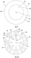
- non-linear fins 220 As shown in Fig. 7 , another embodiment according to the invention of the non-linear fins 220 is shown.
- non-linear fins 220 more proximate to the center C are spaced farther apart from one another than the non-linear fins 220 more proximate to the first wall 104. This is different from the constant spacing between fins 120 of Figs. 1-6 .
- the spacing in Fig. 7 is to keep the hydraulic diameter (l n ) between the non-linear fins 220 constant, which makes the actual distance between fins 220, in the radial direction, vary.
- the hydraulic diameter (l n+1 ) between two of the fins, 220b and 220c is based on the hydraulic diameter (l n ) between the previous two fins, 220a and 220b.
- the non-linear fins 220 are variably spaced apart in a radial direction from center C to the first wall 104. This generally results in the non-linear fins 220 being further apart from one another when they are nearer to the center C and longitudinal axis A and closer to one another when they are closer to first wall 104.
- heat exchanger core 100 provides for reduced size and increased performance by better balancing the hot and cold fluids running through core 100, e.g. through first and second flow paths 106 and 118, respectively. Heat exchanger 100 also increases the heat exchanger effectiveness for a given overall heat transfer area.
- the counter-flow configuration enables high temperature and high pressure operation by reducing the temperature differential across the heat exchanger planform since the cold side outlet and hot side inlet are aligned with one another.
- a method of manufacturing a counter-flow heat exchanger core includes forming heat exchanger core 100 using additive manufacturing such as, selective laser melting (SLM), for example.
- additive manufacturing such as, selective laser melting (SLM), for example.
- powder bed fusion processes can be used (e.g. direct metal laser sintering (DMLS), electron beam melting, selective heat sintering, or the like), or other categories of additive manufacturing can also be used.
- the heat exchanger core can be manufactured in the flow direction, e.g. along longitudinal axis A to avoid horizontal surfaces.
- Heat exchanger core 100 can be manufactured as a single piece, e.g. without any brazing or weld joints.
- a counter-flow heat exchanger 300 includes a heat exchanger core 302 that defines a longitudinal axis X.
- Heat exchanger core 302 includes a primary flow inlet 304, a primary flow outlet 306 and a middle portion 308 therebetween.
- the primary flow direction is indicated schematically by the arrow 301.
- Heat exchanger core 302 is circular cylinder that includes conical tapering portions at its inlet and outlet, 304 and 306, respectively.
- a diameter of heat exchanger core 302 at primary flow inlet 304 is smaller than a diameter of the heat exchanger core 302 in middle portion 308. It is also contemplated that the diameter of core 302 at inlet 304 and in middle portion 308 can be the same, e.g.
- Heat exchanger core 302 can have a constant diameter.
- Heat exchanger core 302 has circular cross-sections along its length, e.g. those taken perpendicular to the flow direction and longitudinal axis X. It is contemplated that heat exchanger core 302 can have a variety of other suitable shapes, for example, it can be an oval cylinder, an elliptical cylinder, a rectangular cylinder, or a square cylinder. In accordance with some embodiments, additional elliptically shaped walls, similar to additional walls 330 can be used inside a rectangular cylinder core.
- the heat exchanger core is substantially linear and defines a longitudinal axis between the primary flow inlet and the primary flow outlet. A radial center of the second wall is aligned with the longitudinal axis.
- heat exchanger core 302 includes an inner wall 310, e.g. a second wall, and an outer wall 312, e.g. a first wall, radially outward and spaced apart from inner wall 310.
- a first flow path 314 is defined within inner wall 310 and outer wall 312 and a second flow path 316 is defined between inner wall 310 and outer wall 312.
- Inner and outer walls, 310 and 312, respectively, define an annulus 315 that includes second flow path 316.
- Inner and outer walls 310 and 312, respectively, are cylindrical and concentric at primary flow inlet 304 of heat exchanger core 302.
- Inner and outer walls, 310 and 312, respectively, are concentric at primary flow outlet of the heat exchanger core.
- Inner wall 310 and outer wall 312 define a second set of channels 320, e.g. channels defined between first and second vane walls, extending axially from primary flow inlet 304 to middle portion 308 of heat exchanger core 302 converging toward radial center A of heat exchanger core 302.
- Respective channels 322 and 324 of the first and second sets of channels 318 and 320 alternate circumferentially with one another to provide additional surface area for heat transfer.
- two channels 322 from first set of channels 318 alternate with one channel 324 from second set of channels 320.
- First and second flow paths 314 and 316 respectively, include vanes 325 to assist with flow distribution with only minimal pressure drop.
- inner wall 310 extends further axially away from flow inlet 304 toward and into middle portion 308, channels 322 of the first set of channels 318 split into multiple sub-channels 326 to maintain a width smaller than a maximum threshold. At least two channels 324 of the second set of channels 320 unite into a single joined channel 328 to maintain a width greater than a minimum threshold.
- additional cylindrical walls 330 are disposed radially inward from outer wall 312 and are concentric with heat exchanger core 302. Additional cylindrical walls 330 are radially spaced apart from one another and are in fluid communication with first and second flow paths 314 and 316, respectively. Additional cylindrical walls 330 are circular cylindrical walls. Additional cylindrical walls 330 are disposed in middle portion 308 of the heat exchanger core 302. It is also contemplated that additional cylindrical walls like cylindrical walls 330 could be used in other portions of heat exchanger core 302.
- annular ring sections 332 are defined between two adjacent additional walls 330 are circumferentially offset with respect to an adjacent annular ring so that a checker-board pattern is formed, e.g. alternating first and second flow paths 314 and 316, respectively, in a radial direction as well as in a circumferential direction.
- the cross-section of Fig. 13 is taken at a similar location as the cross-section of Fig. 12 .
- Each annular ring section 332 includes a portion 322' of one of channels 322 from first set of channels 318 and a portion 324' of one of channels 324 from second set of channels 320.
- Portion 322' from first set of channels 318 in a first annular ring section 332a is offset radially and circumferentially from portion 322' from first set of channels 318 in a second annular ring 332b section.
- Second annular ring section 332b is adjacent to first annular ring section 332a.
- Portion 324' from the second set of channels 320 in first annular ring section 332a is offset radially and circumferentially from portion 324' from second set of channels 320 in second annular ring section 332b.
- heat exchanger 300 provides for reduced size and increased performance by better balancing the hot and cold fluids running through core 302, e.g. through first and second flow paths 314 and 316, respectively. Heat exchanger 300 also increases the heat exchanger effectiveness for a given overall heat transfer area.
- the counter-flow configuration enables high temperature and high pressure operation by reducing the temperature differential across the heat exchanger planform since the cold side outlet and hot side inlet are aligned with one another.
- pressure drops can be reduced and there is not a large discontinuity in stiffness or thermal response as in traditional headering.
- a method of manufacturing a counter-flow heat exchanger core includes forming heat exchanger core 302 using additive manufacturing such as, SLM or DMLS, for example. It is contemplated that the heat exchanger core can be manufactured in the flow direction, e.g. along longitudinal axis X to avoid horizontal surfaces. It is also contemplated that instead of being a linearly extending cylinder, the heat exchanger could be built along a sinusoidal path creating wavy or ruffled sets of channels as opposed to straight ones for increased heat transfer or bend around obstructions.
Landscapes
- Engineering & Computer Science (AREA)
- Physics & Mathematics (AREA)
- Thermal Sciences (AREA)
- Mechanical Engineering (AREA)
- General Engineering & Computer Science (AREA)
- Geometry (AREA)
- Chemical & Material Sciences (AREA)
- Manufacturing & Machinery (AREA)
- Materials Engineering (AREA)
- Heat-Exchange Devices With Radiators And Conduit Assemblies (AREA)
Claims (12)
- Gegenstrom-Wärmetauscherkern (100), umfassend:eine erste Wand (104), die eine Längsachse definiert;einen innerhalb der ersten Wand definierten ersten Strömungspfad (106), wobei der erste Strömungspfad einen primären Strömungseinlass (108) und einen primären Strömungsauslass (110) stromabwärts des primären Strömungseinlasses beinhaltet;mindestens zwei hohle Leitschaufeln (112), die in Umfangsrichtung beabstandet sind und sich von der ersten Wand (104) in einer radial nach innen gerichteten Richtung erstrecken, wobei jede der mindestens zwei hohlen Leitschaufeln eine erste Leitschaufelwand (114) und eine zweite Leitschaufelwand (116) beinhaltet;einen zweiten Strömungspfad, der innerhalb der mindestens zwei hohlen Leitschaufeln zwischen der ersten Leitschaufelwand und der zweiten Leitschaufelwand jeder der mindestens zwei hohlen Leitschaufeln definiert ist; undmindestens eine Rippe, die sich zwischen zwei der mindestens zwei hohlen Leitschaufeln (112) erstreckt;dadurch gekennzeichnet, dass die mindestens eine Rippe mindestens eine nichtlineare Rippe ist, die eine Vielzahl von nichtlinearenRippen (120) zwischen zwei der hohlen Leitschaufeln beinhaltet, wobei die Vielzahl von nichtlinearen Rippen in einer radialen Richtung zu der ersten Wand variabel beabstandet ist.
- Gegenstrom-Wärmetauscherkern nach Anspruch 1, ferner umfassend eine zweite Wand (102) radial innen zu der ersten Wand.
- Gegenstrom-Wärmetauscherkern nach Anspruch 1, wobei die näher an der Längsachse liegenden nichtlinearen Rippen weiter voneinander beabstandet sind als die näher an der ersten Wand (104) liegenden nichtlinearen Rippen (120).
- Gegenstrom-Wärmetauscherkern nach einem der vorhergehenden Ansprüche, wobei der Wärmetauscherkern eine Gehäusewand (122) radial außen zu der ersten Wand beinhaltet.
- Gegenstrom-Wärmetauscherkern nach Anspruch 4,, wobei die Gehäusewand (122) einen zweiten Strömungspfadeinlass (124) und einen zweiten Strömungspfadauslass (126) definiert, wobei der zweite Strömungspfadauslass stromabwärts des zweiten Strömungspfadeinlasses liegt.
- Gegenstrom-Wärmetauscherkern nach Anspruch 4,, wobei ein Fluidverteiler-Einlassmantelrohr (128) zwischen der ersten Wand und der Gehäusewand definiert ist.
- Gegenstrom-Wärmetauscherkern nach Anspruch 6, wobei das Fluidverteiler-Einlassmantelrohr (128) in Fluidverbindung mit dem zweiten Strömungspfad jeder der hohlen Leitschaufeln steht.
- Gegenstrom-Wärmetauscherkern nach Anspruch 6, wobei ein Fluidverteiler-Auslassmantelrohr (130) zwischen der ersten Wand und der Gehäusewand stromabwärts des Fluidverteiler-Einlassmantelrohrs (128) und der in Umfangsrichtung beabstandeten hohlen Leitschaufel definiert ist und wobei die Gehäusewand (122) vorzugsweise einen zweiten Strömungspfadeinlass (124) und einen zweiten Strömungspfadauslass (126) definiert, wobei der zweite Strömungspfadauslass stromabwärts des zweiten Strömungspfadeinlasses und des Fluidverteiler-Auslassmantelrohrs liegt.
- Gegenstrom-Wärmetauscherkern nach Anspruch 4, wobei die Gehäusewand (122) einen zweiten Strömungspfadeinlass (124) und einen zweiten Strömungspfadauslass (126) definiert, wobei sich der zweite Strömungspfadauslass stromabwärts des zweiten Strömungspfadeinlasses befindet, wobei der zweite Strömungspfadeinlass und der zweite Strömungspfadauslass entlang der Längsachse voneinander beabstandet sind und wobei der zweite Strömungspfadeinlass (124) und der zweite Strömungspfadauslass (126) vorzugsweise um 180 Grad zueinander versetzt sind.
- Gegenstrom-Wärmetauscherkern nach einem der vorhergehenden Ansprüche, ferner umfassend eine Innenwand (310) radial innen zu der ersten Wand, wobei die erste Wand eine Außenwand ist, wobei die mindestens zwei hohlen Leitschaufeln durch die Innenwand ausgebildet sind und Kanäle definieren, wobei die erste Leitschaufelwand ein erster Abschnitt der Innenwand ist und die zweite Leitschaufelwand ein zweiter Abschnitt der Innenwand ist, wobei der zweite Strömungspfad mindestens teilweise innerhalb der Kanäle definiert ist und wobei die mindestens eine Rippe vorzugsweise ein Abschnitt einer zylindrischen Wand zwischen der ersten Leitschaufelwand von einer der mindestens zwei Leitschaufeln und der ersten Leitschaufelwand von einer anderen der mindestens zwei Leitschaufeln ist.
- Verfahren zum Fertigen eines Gegenstrom-Wärmetauscherkerns, wobei das Verfahren Folgendes umfasst:
Ausbilden eines Wärmetauscherkernkörpers unter Verwendung von additiver Fertigung, wobei der Wärmetauscherkernkörper Folgendes umfasst:eine erste Wand, die eine Längsachse definiert;einen innerhalb der ersten Wand definierten ersten Strömungspfad, wobei der erste Strömungspfad einen primären Strömungseinlass und einen primären Strömungsauslass stromabwärts des primären Strömungseinlasses beinhaltet;mindestens zwei hohle Leitschaufeln, die in Umfangsrichtung beabstandet sind und sich von der ersten Wand in einer radial nach innen gerichteten Richtung erstrecken, wobei jede der mindestens zwei hohlen Leitschaufeln eine erste Leitschaufelwand und eine zweite Leitschaufelwand beinhaltet;einen zweiten Strömungspfad, der innerhalb der mindestens zwei hohlen Leitschaufeln zwischen der ersten Leitschaufelwand und der zweiten Leitschaufelwand jeder der mindestens zwei hohlen Leitschaufeln definiert ist; undmindestens eine Rippe, die sich zwischen zwei der mindestens zwei hohlen Leitschaufeln erstreckt;dadurch gekennzeichnet, dass die mindestens eine Rippe mindestens eine nichtlineare Rippe ist, die eine Vielzahl von nichtlinearen Rippen zwischen zwei der hohlen Leitschaufeln beinhaltet, wobei die Vielzahl von nichtlinearen Rippen in einer radialen Richtung zu der ersten Wand variabel beabstandet ist. - Verfahren nach Anspruch 11, wobei die additive Fertigung über selektives Laserschmelzen erfolgt.
Applications Claiming Priority (1)
| Application Number | Priority Date | Filing Date | Title |
|---|---|---|---|
| US17/226,973 US11293703B2 (en) | 2016-01-12 | 2021-04-09 | Heat exchangers |
Publications (2)
| Publication Number | Publication Date |
|---|---|
| EP4070957A1 EP4070957A1 (de) | 2022-10-12 |
| EP4070957B1 true EP4070957B1 (de) | 2025-05-28 |
Family
ID=81306765
Family Applications (1)
| Application Number | Title | Priority Date | Filing Date |
|---|---|---|---|
| EP22167678.6A Active EP4070957B1 (de) | 2021-04-09 | 2022-04-11 | Wärmetauscher |
Country Status (1)
| Country | Link |
|---|---|
| EP (1) | EP4070957B1 (de) |
Families Citing this family (2)
| Publication number | Priority date | Publication date | Assignee | Title |
|---|---|---|---|---|
| FR3137753B1 (fr) * | 2022-07-08 | 2024-08-16 | Safran | Echangeur de chaleur a ailettes de hauteur variable et turbomachine correspondante |
| FR3137754B1 (fr) * | 2022-07-08 | 2024-07-05 | Safran | Echangeur de chaleur a ailettes de longueur variable et turbomachine correspondante |
Family Cites Families (6)
| Publication number | Priority date | Publication date | Assignee | Title |
|---|---|---|---|---|
| US4096616A (en) * | 1976-10-28 | 1978-06-27 | General Electric Company | Method of manufacturing a concentric tube heat exchanger |
| FR2465985A1 (fr) * | 1979-09-25 | 1981-03-27 | Ceraver | Structure alveolaire monolithique a grande surface de contact |
| US7128136B2 (en) * | 1998-08-10 | 2006-10-31 | Gregory Christian T | Radial flow heat exchanger |
| US10088250B2 (en) * | 2016-01-12 | 2018-10-02 | Hamilton Sundstrand Corporation | Heat exchangers |
| US10612414B2 (en) * | 2016-08-22 | 2020-04-07 | United Technologies Corporation | Panel based heat exchanger |
| US10406601B2 (en) * | 2017-05-30 | 2019-09-10 | Caterpillar Inc. | 3D printed heat exchanger |
-
2022
- 2022-04-11 EP EP22167678.6A patent/EP4070957B1/de active Active
Also Published As
| Publication number | Publication date |
|---|---|
| EP4070957A1 (de) | 2022-10-12 |
Similar Documents
| Publication | Publication Date | Title |
|---|---|---|
| US11692780B2 (en) | Heat exchangers | |
| US11293703B2 (en) | Heat exchangers | |
| KR102348770B1 (ko) | 곡선형 벽 열교환기 | |
| EP3124906B1 (de) | Gegenstrom-wärmetauscher mit schraubenförmigen kanälen | |
| EP3760962B1 (de) | Wärmetauscher | |
| EP3705830B1 (de) | Kreisförmiger kern für wärmetauscher | |
| EP4070957B1 (de) | Wärmetauscher | |
| EP3789719B1 (de) | Wärmetauscher mit radial konvergierendem verteiler | |
| EP3521742B1 (de) | Wärmetauscher | |
| US10215497B2 (en) | Heat exchanger and production method for heat exchanger | |
| EP3312538B1 (de) | Rippenrohrwärmetauscher | |
| EP3267024B1 (de) | Raketenmotor | |
| EP3839398B1 (de) | Konforme wärmetauscherdurchgangsmerkmale für verbesserte strömungsverteilung | |
| EP3705829B1 (de) | Wärmetauscher | |
| JP3963892B2 (ja) | 平行スロット熱交換器 | |
| GB2285503A (en) | Combustion chamber having a multi-perforated wall | |
| WO2001022019A1 (en) | A spiral heat exchanger | |
| CA2969595C (en) | Improved spiral plate heat exchanger | |
| WO2010087801A1 (en) | Heat exchanger | |
| EP3444554B1 (de) | Wärmetauscherbaugruppe | |
| EP3812685A1 (de) | Mittelkörper in spiralförmigem wärmetauscher |
Legal Events
| Date | Code | Title | Description |
|---|---|---|---|
| PUAI | Public reference made under article 153(3) epc to a published international application that has entered the european phase |
Free format text: ORIGINAL CODE: 0009012 |
|
| STAA | Information on the status of an ep patent application or granted ep patent |
Free format text: STATUS: THE APPLICATION HAS BEEN PUBLISHED |
|
| AK | Designated contracting states |
Kind code of ref document: A1 Designated state(s): AL AT BE BG CH CY CZ DE DK EE ES FI FR GB GR HR HU IE IS IT LI LT LU LV MC MK MT NL NO PL PT RO RS SE SI SK SM TR |
|
| STAA | Information on the status of an ep patent application or granted ep patent |
Free format text: STATUS: REQUEST FOR EXAMINATION WAS MADE |
|
| 17P | Request for examination filed |
Effective date: 20230412 |
|
| RBV | Designated contracting states (corrected) |
Designated state(s): AL AT BE BG CH CY CZ DE DK EE ES FI FR GB GR HR HU IE IS IT LI LT LU LV MC MK MT NL NO PL PT RO RS SE SI SK SM TR |
|
| GRAP | Despatch of communication of intention to grant a patent |
Free format text: ORIGINAL CODE: EPIDOSNIGR1 |
|
| STAA | Information on the status of an ep patent application or granted ep patent |
Free format text: STATUS: GRANT OF PATENT IS INTENDED |
|
| RIC1 | Information provided on ipc code assigned before grant |
Ipc: F28D 9/00 20060101ALI20241112BHEP Ipc: B22F 10/00 20210101ALI20241112BHEP Ipc: F28D 7/08 20060101ALI20241112BHEP Ipc: B33Y 80/00 20150101AFI20241112BHEP |
|
| INTG | Intention to grant announced |
Effective date: 20241212 |
|
| GRAS | Grant fee paid |
Free format text: ORIGINAL CODE: EPIDOSNIGR3 |
|
| GRAA | (expected) grant |
Free format text: ORIGINAL CODE: 0009210 |
|
| STAA | Information on the status of an ep patent application or granted ep patent |
Free format text: STATUS: THE PATENT HAS BEEN GRANTED |
|
| AK | Designated contracting states |
Kind code of ref document: B1 Designated state(s): AL AT BE BG CH CY CZ DE DK EE ES FI FR GB GR HR HU IE IS IT LI LT LU LV MC MK MT NL NO PL PT RO RS SE SI SK SM TR |
|
| REG | Reference to a national code |
Ref country code: GB Ref legal event code: FG4D |
|
| REG | Reference to a national code |
Ref country code: CH Ref legal event code: EP |
|
| REG | Reference to a national code |
Ref country code: IE Ref legal event code: FG4D Ref country code: DE Ref legal event code: R096 Ref document number: 602022015115 Country of ref document: DE |
|
| PG25 | Lapsed in a contracting state [announced via postgrant information from national office to epo] |
Ref country code: ES Free format text: LAPSE BECAUSE OF FAILURE TO SUBMIT A TRANSLATION OF THE DESCRIPTION OR TO PAY THE FEE WITHIN THE PRESCRIBED TIME-LIMIT Effective date: 20250528 Ref country code: FI Free format text: LAPSE BECAUSE OF FAILURE TO SUBMIT A TRANSLATION OF THE DESCRIPTION OR TO PAY THE FEE WITHIN THE PRESCRIBED TIME-LIMIT Effective date: 20250528 |
|
| REG | Reference to a national code |
Ref country code: LT Ref legal event code: MG9D |
|
| PG25 | Lapsed in a contracting state [announced via postgrant information from national office to epo] |
Ref country code: NO Free format text: LAPSE BECAUSE OF FAILURE TO SUBMIT A TRANSLATION OF THE DESCRIPTION OR TO PAY THE FEE WITHIN THE PRESCRIBED TIME-LIMIT Effective date: 20250828 Ref country code: GR Free format text: LAPSE BECAUSE OF FAILURE TO SUBMIT A TRANSLATION OF THE DESCRIPTION OR TO PAY THE FEE WITHIN THE PRESCRIBED TIME-LIMIT Effective date: 20250829 |
|
| PG25 | Lapsed in a contracting state [announced via postgrant information from national office to epo] |
Ref country code: NL Free format text: LAPSE BECAUSE OF FAILURE TO SUBMIT A TRANSLATION OF THE DESCRIPTION OR TO PAY THE FEE WITHIN THE PRESCRIBED TIME-LIMIT Effective date: 20250528 Ref country code: PL Free format text: LAPSE BECAUSE OF FAILURE TO SUBMIT A TRANSLATION OF THE DESCRIPTION OR TO PAY THE FEE WITHIN THE PRESCRIBED TIME-LIMIT Effective date: 20250528 |
|
| PG25 | Lapsed in a contracting state [announced via postgrant information from national office to epo] |
Ref country code: BG Free format text: LAPSE BECAUSE OF FAILURE TO SUBMIT A TRANSLATION OF THE DESCRIPTION OR TO PAY THE FEE WITHIN THE PRESCRIBED TIME-LIMIT Effective date: 20250528 |
|
| PG25 | Lapsed in a contracting state [announced via postgrant information from national office to epo] |
Ref country code: HR Free format text: LAPSE BECAUSE OF FAILURE TO SUBMIT A TRANSLATION OF THE DESCRIPTION OR TO PAY THE FEE WITHIN THE PRESCRIBED TIME-LIMIT Effective date: 20250528 |
|
| PG25 | Lapsed in a contracting state [announced via postgrant information from national office to epo] |
Ref country code: RS Free format text: LAPSE BECAUSE OF FAILURE TO SUBMIT A TRANSLATION OF THE DESCRIPTION OR TO PAY THE FEE WITHIN THE PRESCRIBED TIME-LIMIT Effective date: 20250828 |
|
| PG25 | Lapsed in a contracting state [announced via postgrant information from national office to epo] |
Ref country code: IS Free format text: LAPSE BECAUSE OF FAILURE TO SUBMIT A TRANSLATION OF THE DESCRIPTION OR TO PAY THE FEE WITHIN THE PRESCRIBED TIME-LIMIT Effective date: 20250928 |
|
| PG25 | Lapsed in a contracting state [announced via postgrant information from national office to epo] |
Ref country code: LV Free format text: LAPSE BECAUSE OF FAILURE TO SUBMIT A TRANSLATION OF THE DESCRIPTION OR TO PAY THE FEE WITHIN THE PRESCRIBED TIME-LIMIT Effective date: 20250528 |
|
| REG | Reference to a national code |
Ref country code: AT Ref legal event code: MK05 Ref document number: 1798424 Country of ref document: AT Kind code of ref document: T Effective date: 20250528 |
|
| PG25 | Lapsed in a contracting state [announced via postgrant information from national office to epo] |
Ref country code: DK Free format text: LAPSE BECAUSE OF FAILURE TO SUBMIT A TRANSLATION OF THE DESCRIPTION OR TO PAY THE FEE WITHIN THE PRESCRIBED TIME-LIMIT Effective date: 20250528 Ref country code: AT Free format text: LAPSE BECAUSE OF FAILURE TO SUBMIT A TRANSLATION OF THE DESCRIPTION OR TO PAY THE FEE WITHIN THE PRESCRIBED TIME-LIMIT Effective date: 20250528 Ref country code: SM Free format text: LAPSE BECAUSE OF FAILURE TO SUBMIT A TRANSLATION OF THE DESCRIPTION OR TO PAY THE FEE WITHIN THE PRESCRIBED TIME-LIMIT Effective date: 20250528 |
|
| PG25 | Lapsed in a contracting state [announced via postgrant information from national office to epo] |
Ref country code: CZ Free format text: LAPSE BECAUSE OF FAILURE TO SUBMIT A TRANSLATION OF THE DESCRIPTION OR TO PAY THE FEE WITHIN THE PRESCRIBED TIME-LIMIT Effective date: 20250528 |
|
| PG25 | Lapsed in a contracting state [announced via postgrant information from national office to epo] |
Ref country code: EE Free format text: LAPSE BECAUSE OF FAILURE TO SUBMIT A TRANSLATION OF THE DESCRIPTION OR TO PAY THE FEE WITHIN THE PRESCRIBED TIME-LIMIT Effective date: 20250528 |
|
| PG25 | Lapsed in a contracting state [announced via postgrant information from national office to epo] |
Ref country code: SK Free format text: LAPSE BECAUSE OF FAILURE TO SUBMIT A TRANSLATION OF THE DESCRIPTION OR TO PAY THE FEE WITHIN THE PRESCRIBED TIME-LIMIT Effective date: 20250528 |
|
| PG25 | Lapsed in a contracting state [announced via postgrant information from national office to epo] |
Ref country code: IT Free format text: LAPSE BECAUSE OF FAILURE TO SUBMIT A TRANSLATION OF THE DESCRIPTION OR TO PAY THE FEE WITHIN THE PRESCRIBED TIME-LIMIT Effective date: 20250528 |
|
| REG | Reference to a national code |
Ref country code: DE Ref legal event code: R097 Ref document number: 602022015115 Country of ref document: DE |
|
| PLBE | No opposition filed within time limit |
Free format text: ORIGINAL CODE: 0009261 |
|
| STAA | Information on the status of an ep patent application or granted ep patent |
Free format text: STATUS: NO OPPOSITION FILED WITHIN TIME LIMIT |
|
| PGFP | Annual fee paid to national office [announced via postgrant information from national office to epo] |
Ref country code: GB Payment date: 20260319 Year of fee payment: 5 |
|
| REG | Reference to a national code |
Ref country code: CH Ref legal event code: L10 Free format text: ST27 STATUS EVENT CODE: U-0-0-L10-L00 (AS PROVIDED BY THE NATIONAL OFFICE) Effective date: 20260409 |