EP4070909B1 - Coordinate pattern file creating device, trajectory pattern creating device, and method for controlling laser processing machine - Google Patents
Coordinate pattern file creating device, trajectory pattern creating device, and method for controlling laser processing machine Download PDFInfo
- Publication number
- EP4070909B1 EP4070909B1 EP20895407.3A EP20895407A EP4070909B1 EP 4070909 B1 EP4070909 B1 EP 4070909B1 EP 20895407 A EP20895407 A EP 20895407A EP 4070909 B1 EP4070909 B1 EP 4070909B1
- Authority
- EP
- European Patent Office
- Prior art keywords
- pattern
- coordinate
- locus
- locus pattern
- unit
- Prior art date
- Legal status (The legal status is an assumption and is not a legal conclusion. Google has not performed a legal analysis and makes no representation as to the accuracy of the status listed.)
- Active
Links
- 238000000034 method Methods 0.000 title claims description 31
- 229910052751 metal Inorganic materials 0.000 claims description 83
- 239000002184 metal Substances 0.000 claims description 83
- 238000004364 calculation method Methods 0.000 claims description 77
- 238000004088 simulation Methods 0.000 claims description 31
- 230000007246 mechanism Effects 0.000 claims description 30
- 230000014759 maintenance of location Effects 0.000 claims description 12
- 238000010586 diagram Methods 0.000 description 32
- 230000008569 process Effects 0.000 description 14
- 239000007789 gas Substances 0.000 description 12
- 238000003466 welding Methods 0.000 description 7
- 239000000835 fiber Substances 0.000 description 5
- 230000006870 function Effects 0.000 description 5
- IJGRMHOSHXDMSA-UHFFFAOYSA-N Atomic nitrogen Chemical compound N#N IJGRMHOSHXDMSA-UHFFFAOYSA-N 0.000 description 4
- 230000003287 optical effect Effects 0.000 description 4
- 238000003672 processing method Methods 0.000 description 3
- XEEYBQQBJWHFJM-UHFFFAOYSA-N Iron Chemical compound [Fe] XEEYBQQBJWHFJM-UHFFFAOYSA-N 0.000 description 2
- QVGXLLKOCUKJST-UHFFFAOYSA-N atomic oxygen Chemical compound [O] QVGXLLKOCUKJST-UHFFFAOYSA-N 0.000 description 2
- 239000003086 colorant Substances 0.000 description 2
- 238000004590 computer program Methods 0.000 description 2
- 238000006073 displacement reaction Methods 0.000 description 2
- 239000000463 material Substances 0.000 description 2
- 229910052757 nitrogen Inorganic materials 0.000 description 2
- 239000001301 oxygen Substances 0.000 description 2
- 229910052760 oxygen Inorganic materials 0.000 description 2
- 230000000717 retained effect Effects 0.000 description 2
- 239000004229 Alkannin Substances 0.000 description 1
- 229910001369 Brass Inorganic materials 0.000 description 1
- 230000009471 action Effects 0.000 description 1
- 239000003570 air Substances 0.000 description 1
- 229910052782 aluminium Inorganic materials 0.000 description 1
- XAGFODPZIPBFFR-UHFFFAOYSA-N aluminium Chemical compound [Al] XAGFODPZIPBFFR-UHFFFAOYSA-N 0.000 description 1
- 239000010951 brass Substances 0.000 description 1
- 244000309466 calf Species 0.000 description 1
- 230000008859 change Effects 0.000 description 1
- 230000001419 dependent effect Effects 0.000 description 1
- 230000005284 excitation Effects 0.000 description 1
- 229910052742 iron Inorganic materials 0.000 description 1
- 238000012986 modification Methods 0.000 description 1
- 230000004048 modification Effects 0.000 description 1
- 239000004172 quinoline yellow Substances 0.000 description 1
- 239000007787 solid Substances 0.000 description 1
- 229910001220 stainless steel Inorganic materials 0.000 description 1
- 239000010935 stainless steel Substances 0.000 description 1
- 238000009941 weaving Methods 0.000 description 1
Images


Classifications
-
- B—PERFORMING OPERATIONS; TRANSPORTING
- B23—MACHINE TOOLS; METAL-WORKING NOT OTHERWISE PROVIDED FOR
- B23K—SOLDERING OR UNSOLDERING; WELDING; CLADDING OR PLATING BY SOLDERING OR WELDING; CUTTING BY APPLYING HEAT LOCALLY, e.g. FLAME CUTTING; WORKING BY LASER BEAM
- B23K26/00—Working by laser beam, e.g. welding, cutting or boring
- B23K26/08—Devices involving relative movement between laser beam and workpiece
- B23K26/082—Scanning systems, i.e. devices involving movement of the laser beam relative to the laser head
-
- B—PERFORMING OPERATIONS; TRANSPORTING
- B23—MACHINE TOOLS; METAL-WORKING NOT OTHERWISE PROVIDED FOR
- B23K—SOLDERING OR UNSOLDERING; WELDING; CLADDING OR PLATING BY SOLDERING OR WELDING; CUTTING BY APPLYING HEAT LOCALLY, e.g. FLAME CUTTING; WORKING BY LASER BEAM
- B23K26/00—Working by laser beam, e.g. welding, cutting or boring
- B23K26/36—Removing material
- B23K26/38—Removing material by boring or cutting
-
- B—PERFORMING OPERATIONS; TRANSPORTING
- B23—MACHINE TOOLS; METAL-WORKING NOT OTHERWISE PROVIDED FOR
- B23K—SOLDERING OR UNSOLDERING; WELDING; CLADDING OR PLATING BY SOLDERING OR WELDING; CUTTING BY APPLYING HEAT LOCALLY, e.g. FLAME CUTTING; WORKING BY LASER BEAM
- B23K26/00—Working by laser beam, e.g. welding, cutting or boring
- B23K26/08—Devices involving relative movement between laser beam and workpiece
- B23K26/0869—Devices involving movement of the laser head in at least one axial direction
- B23K26/0876—Devices involving movement of the laser head in at least one axial direction in at least two axial directions
-
- B—PERFORMING OPERATIONS; TRANSPORTING
- B23—MACHINE TOOLS; METAL-WORKING NOT OTHERWISE PROVIDED FOR
- B23K—SOLDERING OR UNSOLDERING; WELDING; CLADDING OR PLATING BY SOLDERING OR WELDING; CUTTING BY APPLYING HEAT LOCALLY, e.g. FLAME CUTTING; WORKING BY LASER BEAM
- B23K37/00—Auxiliary devices or processes, not specially adapted to a procedure covered by only one of the preceding main groups
- B23K37/02—Carriages for supporting the welding or cutting element
- B23K37/0211—Carriages for supporting the welding or cutting element travelling on a guide member, e.g. rail, track
- B23K37/0235—Carriages for supporting the welding or cutting element travelling on a guide member, e.g. rail, track the guide member forming part of a portal
-
- B—PERFORMING OPERATIONS; TRANSPORTING
- B23—MACHINE TOOLS; METAL-WORKING NOT OTHERWISE PROVIDED FOR
- B23K—SOLDERING OR UNSOLDERING; WELDING; CLADDING OR PLATING BY SOLDERING OR WELDING; CUTTING BY APPLYING HEAT LOCALLY, e.g. FLAME CUTTING; WORKING BY LASER BEAM
- B23K37/00—Auxiliary devices or processes, not specially adapted to a procedure covered by only one of the preceding main groups
- B23K37/04—Auxiliary devices or processes, not specially adapted to a procedure covered by only one of the preceding main groups for holding or positioning work
- B23K37/0408—Auxiliary devices or processes, not specially adapted to a procedure covered by only one of the preceding main groups for holding or positioning work for planar work
-
- G—PHYSICS
- G05—CONTROLLING; REGULATING
- G05B—CONTROL OR REGULATING SYSTEMS IN GENERAL; FUNCTIONAL ELEMENTS OF SUCH SYSTEMS; MONITORING OR TESTING ARRANGEMENTS FOR SUCH SYSTEMS OR ELEMENTS
- G05B19/00—Programme-control systems
- G05B19/02—Programme-control systems electric
- G05B19/18—Numerical control [NC], i.e. automatically operating machines, in particular machine tools, e.g. in a manufacturing environment, so as to execute positioning, movement or co-ordinated operations by means of programme data in numerical form
- G05B19/406—Numerical control [NC], i.e. automatically operating machines, in particular machine tools, e.g. in a manufacturing environment, so as to execute positioning, movement or co-ordinated operations by means of programme data in numerical form characterised by monitoring or safety
- G05B19/4069—Simulating machining process on screen
-
- G—PHYSICS
- G05—CONTROLLING; REGULATING
- G05B—CONTROL OR REGULATING SYSTEMS IN GENERAL; FUNCTIONAL ELEMENTS OF SUCH SYSTEMS; MONITORING OR TESTING ARRANGEMENTS FOR SUCH SYSTEMS OR ELEMENTS
- G05B19/00—Programme-control systems
- G05B19/02—Programme-control systems electric
- G05B19/18—Numerical control [NC], i.e. automatically operating machines, in particular machine tools, e.g. in a manufacturing environment, so as to execute positioning, movement or co-ordinated operations by means of programme data in numerical form
- G05B19/4097—Numerical control [NC], i.e. automatically operating machines, in particular machine tools, e.g. in a manufacturing environment, so as to execute positioning, movement or co-ordinated operations by means of programme data in numerical form characterised by using design data to control NC machines, e.g. CAD/CAM
-
- G—PHYSICS
- G05—CONTROLLING; REGULATING
- G05B—CONTROL OR REGULATING SYSTEMS IN GENERAL; FUNCTIONAL ELEMENTS OF SUCH SYSTEMS; MONITORING OR TESTING ARRANGEMENTS FOR SUCH SYSTEMS OR ELEMENTS
- G05B19/00—Programme-control systems
- G05B19/02—Programme-control systems electric
- G05B19/18—Numerical control [NC], i.e. automatically operating machines, in particular machine tools, e.g. in a manufacturing environment, so as to execute positioning, movement or co-ordinated operations by means of programme data in numerical form
- G05B19/41—Numerical control [NC], i.e. automatically operating machines, in particular machine tools, e.g. in a manufacturing environment, so as to execute positioning, movement or co-ordinated operations by means of programme data in numerical form characterised by interpolation, e.g. the computation of intermediate points between programmed end points to define the path to be followed and the rate of travel along that path
- G05B19/4103—Digital interpolation
-
- B—PERFORMING OPERATIONS; TRANSPORTING
- B23—MACHINE TOOLS; METAL-WORKING NOT OTHERWISE PROVIDED FOR
- B23K—SOLDERING OR UNSOLDERING; WELDING; CLADDING OR PLATING BY SOLDERING OR WELDING; CUTTING BY APPLYING HEAT LOCALLY, e.g. FLAME CUTTING; WORKING BY LASER BEAM
- B23K2101/00—Articles made by soldering, welding or cutting
- B23K2101/18—Sheet panels
-
- G—PHYSICS
- G05—CONTROLLING; REGULATING
- G05B—CONTROL OR REGULATING SYSTEMS IN GENERAL; FUNCTIONAL ELEMENTS OF SUCH SYSTEMS; MONITORING OR TESTING ARRANGEMENTS FOR SUCH SYSTEMS OR ELEMENTS
- G05B2219/00—Program-control systems
- G05B2219/30—Nc systems
- G05B2219/36—Nc in input of data, input key till input tape
- G05B2219/36199—Laser cutting
-
- G—PHYSICS
- G05—CONTROLLING; REGULATING
- G05B—CONTROL OR REGULATING SYSTEMS IN GENERAL; FUNCTIONAL ELEMENTS OF SUCH SYSTEMS; MONITORING OR TESTING ARRANGEMENTS FOR SUCH SYSTEMS OR ELEMENTS
- G05B2219/00—Program-control systems
- G05B2219/30—Nc systems
- G05B2219/45—Nc applications
- G05B2219/45041—Laser cutting
Definitions
- the present disclosure relates to a coordinate pattern file creation device, a locus pattern creation device, and a method of controlling a laser processing machine.
- Patent Literatures 1 and 2 describe cutting a sheet metal while vibrating a laser beam in a predetermined locus pattern (vibration pattern) by means of a galvano scanner unit.
- Patent Application EP 2 508 293 A1 relates to a robot system, including a laser emitting portion capable of emitting a laser beam to a welding locus.
- This robot system includes a robot moving the laser emitting portion, and capable of scanning a welding locus with a laser beam at least in a state where the laser emitting portion does not move, and a control portion controlling the laser emitting portion to scan the welding locus with the laser beam in order to perform welding with weaving on the welding locus at least in the state where the laser emitting portion does not move.
- Patent Application US 2018/164793 A1 relates to a laser processing robot system that carries out laser processing by using a robot.
- the laser processing robot system includes a laser irradiation device carrying out an irradiation point shifting operation, a robot moving the laser irradiation device, a laser irradiation device controller controlling the irradiation point shifting operation, and a robot controller controlling the robot.
- the robot controller instructs the robot on a plurality of first interpolated positions at every first interpolation period, and outputs a command value associated with the irradiation point shifting operation to the laser irradiation device controller at every second interpolation period shorter than the first interpolation period.
- a galvano scanner unit includes a pair of scan mirrors, and vibrates a laser beam with which a sheet metal is irradiated by reciprocatively vibrating one or both of the pair of scan mirrors.
- a drive unit that drives the scan mirrors vibrates the scan mirrors in a sine wave shape. This is because it enables the drive unit to smoothly move the scan mirrors.
- a beam spot of the laser beam can be vibrated only in specific locus patterns as described in Patent Literature 2.
- the specific locus patterns include a parallel vibration pattern in which the beam spot of the laser beam is vibrated in a direction parallel to a cutting travelling direction, and an orthogonal vibration pattern in which the beam spot is vibrated in a direction orthogonal to the cutting travelling direction.
- Other specific locus patterns include a circular vibration pattern in which the beam spot is vibrated in such a manner as to draw a circle, an 8-shaped vibration pattern in which the beam spot is vibrated in such a manner as to draw a shape of the number eight, and a c-shaped vibration pattern in which the beam spot is vibrated in such a manner as to draw a shape of the alphabet C.
- the locus pattern here is a pattern drawn only by vibrating the laser beam with the galvano scanner unit in a state in which a processing head that emits the laser beam is not moved.
- the actual locus pattern when the sheet metal is cut is a locus pattern in which a displacement due to a movement of the processing head is added to the locus pattern by the galvano scanner unit.
- a locus pattern creation device for vibrating the laser beam in an arbitrary waveform shape and a method of controlling a laser processing machine capable of vibrating the laser beam in the arbitrary waveform shape to process the sheet metal are required.
- a coordinate pattern file creation device capable of creating a coordinate pattern file for determining a locus pattern after confirming in advance in what locus patterns the laser beam can be vibrated is required.
- An object of one or more embodiments is to provide a coordinate pattern file creation device capable of creating a coordinate pattern file for determining a locus pattern after confirming in advance the locus pattern to be drawn by a beam spot of a laser beam.
- An object of the present invention is to provide a locus pattern creation device capable of creating the locus pattern for vibrating the laser beam in an arbitrary waveform shape, and a method of controlling a laser machine capable of vibrating the laser beam in the arbitrary waveform shape to process the sheet metal.
- a coordinate pattern file creation device is provided according to claim 1.
- a locus pattern creation device is provided according to claim 6.
- a method for controlling, by an NC device, a laser processing machine is provided according to claim 10.
- the coordinate pattern file creation device of the one or more embodiments it is possible to create a coordinate pattern file for determining a locus pattern after confirming in advance the locus pattern to be drawn by a beam spot of a laser beam.
- the locus pattern creation device of the present invention it is possible to create the locus pattern for vibrating the laser beam in an arbitrary waveform shape.
- the laser beam can be vibrated in an arbitrary waveform shape to process a sheet metal.
- a laser processing machine 100 includes a laser oscillator 10 that generates and emits a laser beam, a laser processing unit 20, and a process fiber 12 that transmits the laser beam emitted from the laser oscillator 10 to the laser processing unit 20. Further, the laser processing machine 100 includes an operation unit 40, an NC device 50, an assist gas supply device 80, and a display unit 90.
- the NC device 50 is an example of a control device that controls each part of the laser processing machine 100.
- a processing program database 60, a processing condition database 70, and a coordinate pattern file database 75 are connected to the NC device 50.
- the processing program database 60, the processing condition database 70, and the coordinate pattern file database 75 may be provided in the laser processing machine 100, or may be provided outside the laser processing machine 100. In the latter case, the processing program database 60, the processing condition database 70, and the coordinate pattern file database 75 may be configured to be connected to the laser processing machine 100 via a network.
- a preferable laser oscillator is the one that amplifies an excitation beam emitted from a laser diode and emits a laser beam having a predetermined wavelength, or the one that directly uses the laser beam emitted from the laser diode.
- the laser oscillator 10 is, for example, a solid laser oscillator, a fiber laser oscillator, a disk laser oscillator, or a direct diode laser oscillator (a DDL oscillator).
- the laser oscillator 10 emits a laser beam in a 1 ⁇ m band having a wavelength of 900 nm to 1100 nm.
- the fiber laser oscillator emits a laser beam having a wavelength of 1060 nm to 1080 nm
- the DDL oscillator emits a laser beam having a wavelength of 910 nm to 950 nm.
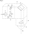
- the laser processing unit 20 includes a processing table 21 on which a sheet metal W to be processed is placed, a gate-shaped X-axis carriage 22, a Y-axis carriage 23, a collimator unit 30 fixed to the Y-axis carriage 23, and a processing head 35.
- the X-axis carriage 22 is configured to be movable in the X-axis direction on the processing table 21.
- the Y-axis carriage 23 is configured to be movable on the X-axis carriage 22 in the Y-axis direction perpendicular to the X-axis.
- the X-axis carriage 22 and the Y-axis carriage 23 function as a moving mechanism for moving the processing head 35 along the surface of the sheet metal W in the X-axis direction, the Y-axis direction, or a direction in which the X-axis direction and the Y-axis direction are arbitrarily combined.
- the processing head 35 may be configured such that the position thereof is fixed and the sheet metal W moves.
- the laser processing machine 100 may include a moving mechanism for relatively moving the processing head 35 with respect to the surface of the sheet metal W.
- the processing head 35 includes a circular opening 36a at the tip end portion thereof, and a nozzle 36 that emits a laser beam from the opening 36a is attached thereto.
- the sheet metal W is irradiated with the laser beam emitted from the opening 36a of the nozzle 36.
- the assist gas supply device 80 supplies nitrogen, oxygen, a mixed gas of nitrogen and oxygen, or air as an assist gas to the processing head 35.
- the assist gas is blown onto the sheet metal W from the opening 36a.
- the assist gas discharges a molten metal within a calf width in which the sheet metal W is melted.
- the collimator unit 30 includes a collimation lens 31 that converts the laser beam, which is a divergent beam emitted from the process fiber 12, into a parallel beam (a collimated beam). Further, the collimator unit 30 includes a galvano scanner unit 32, and a bend mirror 33 that reflects the laser beam emitted from the galvano scanner unit 32 downward in the Z-axis direction perpendicular to the X-axis and the Y-axis.
- the processing head 35 includes a focusing lens 34 that focuses the laser beam reflected by the bend mirror 33 to irradiate the sheet metal W with the laser beam.
- the focusing lens 34 is configured to be movable in a direction approaching the sheet metal W and a direction away from the sheet metal W by means of an unillustrated drive unit and moving mechanism.
- the laser processing machine 100 is centered so that the laser beam emitted from the opening 36a of the nozzle 36 is located at the center of the opening 36a. In the reference state, the laser beam is emitted from the center of the opening 36a.
- the galvano scanner unit 32 functions as a beam vibration mechanism for vibrating the laser beam, which moves in the processing head 35 and is emitted from the opening 36a, in the opening 36a.
- the galvano scanner unit 32 includes a scan mirror 321 that reflects the laser beam emitted from the collimation lens 31, and a drive unit 322 that rotates the scan mirror 321 in such a manner as to have a predetermined angle. Further, the galvano scanner unit 32 includes a scan mirror 323 that reflects the laser beam emitted from the scan mirror 321 and a drive unit 324 that rotates the scan mirror 323 in such a manner as to have a predetermined angle.
- the drive units 322 and 324 can be configured by a motor.
- the drive units 322 and 324 can reciprocatively vibrate the scan mirrors 321 and 323 within a predetermined angle range, respectively, based on the control by the NC device 50. By reciprocatively vibrating either one or both of the scan mirrors 321 and 323, the galvano scanner unit 32 vibrates the laser beam with which the sheet metal W is irradiated.
- the galvano scanner unit 32 is an example of the beam vibration mechanism, and the beam vibration mechanism is not limited to the galvano scanner unit 32 including the pair of scan mirrors.
- Figure 3 shows a state in which either one or both of the scan mirrors 321 and 323 are tilted and the position of the laser beam with which the sheet metal W is irradiated is displaced.
- the fine solid line that is bent by the bend mirror 33 and passes through the focusing lens 34 indicates the optical axis of the laser beam when the laser processing machine 100 is in the reference state.
- the galvano scanner unit 32 located in front of the bend mirror 33 by operating the galvano scanner unit 32 located in front of the bend mirror 33, the angle of the optical axis of the laser beam to be made incident on the bend mirror 33 is changed, which causes the optical axis to deviate from the center of the bend mirror 33.
- the incident position of the laser beam on the bend mirror 33 is set to the same position before and after the operation of the galvano scanner unit 32.
- the optical axis of the laser beam is displaced from the position indicated by the thin solid line to the position indicated by the thick solid line due to the action of the galvano scanner unit 32.
- the laser beam reflected by the bend mirror 33 is tilted at an angle ⁇
- the irradiation position on the sheet metal W of the laser beam is displaced by a distance ⁇ s .
- the focal length of the focusing lens 34 is EFL (Effective Focal Length)
- the distance ⁇ s is calculated by EFL ⁇ sin ⁇ .
- the irradiation position on the sheet metal W of the laser beam can be displaced by the distance ⁇ s in the direction opposite to the direction shown in Figure 3 .
- the distance ⁇ s is a distance less than a radius of the opening 36a, and preferably a distance equal to or less than the maximum distance when the distance obtained by subtracting a predetermined margin from the radius of the opening 36a is the maximum distance.
- the NC device 50 can vibrate the laser beam in a predetermined direction in the surface of the sheet metal W by controlling the drive units 322 and 324 of the galvano scanner unit 32. By vibrating the laser beam, a beam spot formed on the surface of the sheet metal W can be vibrated.
- the laser processing machine 100 configured as described above cuts the sheet metal W by means of the laser beam emitted from the laser oscillator 10 to produce a product having a predetermined shape.
- the laser processing machine 100 locates the focal point of the laser beam at an appropriate position of any one from within the thickness of the sheet metal W, on the top surface of the sheet metal W, above the top surface by a predetermined distance, or below the top surface by a predetermined distance, and cuts the sheet metal while vibrating the laser beam in a predetermined locus pattern.
- the processing program database 60 stores a processing program for cutting the sheet metal W.
- the NC device 50 reads out the processing program from the processing program database 60 and selects one of a plurality of processing condition files stored in the processing condition database 70.
- the NC device 50 controls the laser processing machine 100 so as to cut the sheet metal W based on the processing conditions set in the read processing program and the selected processing condition file.
- the coordinate pattern file database 75 stores a coordinate pattern file that is used when a locus pattern for vibrating the laser beam is determined. The details of the coordinate pattern file will be described later.
- the NC device 50 vibrates the laser beam at the time of cutting the sheet metal W, the NC device 50 reads out a desired coordinate pattern file from the coordinate pattern file database 75.
- the NC device 50 uses the read coordinate pattern file to determine a locus pattern, and controls the galvano scanner unit 32 so as to vibrate the laser beam.
- Figure 4 shows a coordinate pattern file creation device 200 of one or more embodiments capable of simulating the locus pattern to create the coordinate pattern file.
- the coordinate pattern file creation device 200 includes a coordinate input unit 201, a locus pattern simulation unit 202, and a coordinate pattern file creation unit 205.
- the locus pattern simulation unit 202 includes an interpolation parameter calculation unit 203 and a locus pattern calculation unit 204.
- the coordinate pattern file creation device 200 shown in Figure 4 can be configured by a computer device 210 shown in Figure 5 .
- the computer device 210 includes a central processing unit (CPU) 211, a non-transitory storage medium 212, a main memory 213, and a network connection unit 214.
- the computer device 210 is provided with a display unit 215 and an operation unit 216, or the display unit 215 and the operation unit 216 are connected to the computer device 210.
- the storage medium 212 stores a coordinate pattern file creation program that is a computer program for creating the coordinate pattern file.
- the coordinate pattern file creation device 200 shown in Figure 4 is configured by the CPU 211 loading the coordinate pattern file creation program into the main memory 213 and executing the coordinate pattern file creation program.
- the display unit 215 and the operation unit 216 function as the coordinate input unit 201.
- the operation unit 216 may be a keyboard, or a touch panel that is mounted on a screen of the display unit 215.
- the coordinate pattern file creation device 200 shown in Figure 4 creates a coordinate pattern file for obtaining the 8-shaped vibration pattern.
- the beam spot represented by a circle vibrates in such a manner as to move in the order indicated by the numbers in the beam spots.
- the beam spot at the position indicated by the number 8 moves to the position indicated by the number 1, and repeats vibrating.
- the 8-shaped vibration pattern shown in Figure 6 is a pattern drawn only by the galvano scanner unit 32 vibrating the beam spot while the processing head 35 is not moving.
- the flowcharts shown in Figures 7 and 8 show the processing executed by the coordinate pattern file creation device 200.
- the CPU 211 executes the coordinate pattern file creation program, in step S201 of Figure 7 , the CPU 211 displays, on the display unit 215, a coordinate value input window 220 shown in Figure 9 .
- the coordinate value input window 220 corresponds to at least a part of the coordinate input unit 201.
- the coordinate value input window 220 includes a coordinate value input field 221 for inputting a plurality of coordinate values (first plurality of coordinate values) constituting a coordinate pattern that is the original data for determining the locus pattern of one cycle, and a coordinate pattern display area 222 for displaying the coordinate pattern.
- the coordinate value input window 220 includes a read-out button 223 for reading out the coordinate pattern file stored in the coordinate pattern file database 75, a clear button 224, and a simulation instruction button 225.
- the cutting travelling direction of the sheet metal W which is the moving direction of the processing head 35, is defined as the x-axis direction, and the direction orthogonal to the x-axis direction in the surface of the sheet metal W is defined as the y-axis direction.
- the x-axis direction and the y-axis direction are determined depending on the moving direction in which the X-axis carriage 22 and the Y-axis carriage 23 move the processing head 35 along the surface of the sheet metal W in the X-axis direction, the Y-axis direction, or the direction in which the X-axis direction and the Y-axis direction are arbitrarily combined.
- step S202 an operator inputs, in the coordinate value input field 221, a plurality of coordinate values that constitutes the coordinate pattern.
- the operator inputs, in the fields of the numbers 1 to 7 of the coordinate value input field 221, (0, 0), (-50, 25), (0, 50), (50, 25), (0, 0), (-50, -25), (0, -50), and (50, -25), respectively, as the coordinate values of (x, y).
- the coordinate pattern display area 222 the coordinate pattern corresponding to the plurality of coordinate values input in the coordinate value input field 221 is displayed.
- the coordinate value that is checked in the field indicated as Start in the coordinate value input field 221 is a start coordinate of the coordinate pattern.
- the coordinate pattern for obtaining the 8-shaped vibration pattern shown in Figure 6 is the coordinate pattern shown in Figure 10 .
- the display range of the coordinate pattern display area 222 in Figure 10 in the x-axis direction and the y-axis direction is different from the display range in Figure 9 in correspondence to the plurality of coordinate values input in the coordinate value input field 221.
- step S203 the CPU 211 determines whether or not an instruction for simulation has been given. If the instruction for simulation has not been given (NO), the processing of steps S202 and S203 are repeated.
- the CPU 211 an interpolation parameter calculation unit 203 calculates in step S204 an interpolation parameter of cubic spline interpolation based on the input coordinate values.
- the calculation method of the cubic spline interpolation includes various interpolation calculation formulae (interpolation methods) such as natural spline interpolation and Akima spline interpolation.
- interpolation methods such as natural spline interpolation and Akima spline interpolation.
- the interpolation formula to be used is selected.
- the CPU 211 calculates the interpolation parameters in the x-axis direction and the y-axis direction, respectively.
- the interpolation parameters are coefficients a, b, c, and d of piecewise polynomials S i (x) and S i (y) represented by the equations (1) and (2) that are used in the cubic spline interpolation.
- the piecewise polynomial S i (x) is a cubic polynomial that interpolates between a coordinate value x i and a coordinate value x i + 1 that are discrete points.
- the piecewise polynomial S i (y) is a cubic polynomial that interpolates between a coordinate value yi and a coordinate value y i + 1 that are discrete points.
- S i x a i + b i x ⁇ x i + c i x ⁇ x i 2 + d i x ⁇ x i 3
- S i y a i + b i y ⁇ y i + c i y ⁇ y i 2 + d i y ⁇ y i 3
- the equations (3) and (4) using a parameter u are used.
- the parameter u is from 0 to the number obtained by subtracting 1 from the number of coordinate values, that is, 0 to 6.
- the parameter u is the coordinate number value that is input in order, and by moving between the respective coordinate values in an equal time and completing the movement of one cycle, the interpolation calculation formulae of the coordinate value in the x-axis direction - the input coordinate number value (time) and the coordinate value in the y-axis direction - the input coordinate number value (time) are obtained.
- step S205 the CPU 211 (the locus pattern calculation unit 204) creates a locus pattern based on the interpolation parameter, simulation conditions, and a control cycle of the galvano scanner unit 32.
- step S206 the CPU 211 (the locus pattern calculation unit 204) creates a moving locus pattern in which the locus pattern is moved in the cutting travelling direction based on the simulation conditions.
- step S206 the CPU 211 displays the locus pattern display window 230 shown in Figure 11 on the display unit 215.
- the locus pattern display window 230 includes a condition input unit 231 for inputting the simulation conditions, a locus pattern display area 232 for displaying the locus pattern and the moving locus pattern, and an output instruction button 233 for instructing an output of the coordinate pattern file.
- the condition input unit 231 includes an input unit for a moving velocity of the processing head 35, which is indicated as Speed, an input unit for the amplitude of the locus pattern in the x-axis direction, which is indicated as Qx, and an input unit for the amplitude of the locus pattern in the y-axis direction, which is indicated as Qy.
- condition input unit 231 includes an input unit of a frequency at which the laser beam is vibrated, which is indicated as Frequency, a rotational angle at which the locus pattern is rotated, which is indicated as Angle, and a selection unit for the interpolation calculation formula, which is indicated as Spline.
- the natural spline interpolation Natural
- Akima spline interpolation Akima
- the interpolation calculation formula used in step S204 is selected in the selection unit of the interpolation calculation formula.
- the natural spline interpolation is used in step S204, and thus the natural spline interpolation is selected.
- the interpolation calculation formula of the spline interpolation is used as an example of the interpolation calculation formula, but the interpolation calculation formula of any other interpolation method may be used as long as a predetermined interpolation calculation formula is used.
- the simulation conditions used in step S205 are the amplitudes Qx and Qy, the frequency, the rotational angle of the locus pattern, and the interpolation calculation formula that has been set in the condition input unit 231.
- the simulation conditions used in step S206 are the moving velocity and the frequency of the processing head 35 that has been set in the condition input unit 231.
- FIG. 8 shows the detailed processing of step S205.
- the CPU 211 the locus pattern calculation unit 204 calculates the number of coordinates required to form the locus pattern corresponding to the frequency set in the frequency input unit of the condition input unit 231.
- the frequency is 1000 Hz
- the control cycle of the galvano scanner unit 32 is 1 ⁇ s.
- the number of coordinates required for the locus pattern is 1000 ⁇ s/1 ⁇ s, which is 1000.
- step S2052 the CPU 211 (the locus pattern calculation unit 204) calculates a plurality of coordinate values (second plurality of coordinate values) that are interpolation points constituting the locus pattern. At this time, the CPU 211 (the locus pattern calculation unit 204) calculates the coordinate value of the locus pattern in the x-axis direction and the coordinate value thereof in the y-axis direction, respectively, by using the interpolation parameter of the x-axis and the interpolation parameter of the y-axis.
- the respective coordinate values are calculated as follows.
- the case is taken as an example in which the coordinate value of the input coordinate pattern is 25.
- the interpolation points to be interpolated by the cubic spline interpolation are 1000 coordinates of 0, 0.024, 0.048, 0.072, ... 23.928, 23.952, and 23.976 in each of the x-axis direction and the y-axis direction at 0.024 intervals, which is obtained by subtracting 1 from the input coordinate value and dividing the input coordinate number value by the number of coordinates of 1000.
- Each coordinate value of the locus pattern is determined by the coordinate value in the x-axis direction and the coordinate value in the y-axis direction having the coordinate values of the same interpolation point obtained by the interpolation point and the interpolation parameter.
- the coordinate value having the interpolation point 0 in the x-axis direction and the coordinate value having the interpolation point 0 in the y-axis direction determine the coordinate value of the first interpolation point
- the coordinate value having the interpolation point 0.024 in the x-axis direction and the coordinate value having the interpolation point 0.024 in the y-axis direction determines the coordinate value of the second interpolation point.
- step S2053 the CPU 211 (the locus pattern calculation unit 204) enlarges or reduces coordinate data indicating the position of each coordinate of the locus pattern according to the amplitudes Qx and Qy.
- step S2054 the CPU 211 (the locus pattern calculation unit 204) determines whether or not the distance between the coordinates is within the limit value. The distance between the coordinates changes according to the frequency and the amplitudes Qx and Qy. There is an upper limit to the angular velocity at which the scan mirrors 321 and 323 of the galvano scanner unit 32 change the angle. Even in a part of the locus pattern, if the distance between the coordinates exceeds the movable distance at the upper limit value of the angular velocity, the locus pattern cannot be drawn. Thus, such a locus pattern is unusable.
- a locus pattern Tp and a moving locus pattern MTp are displayed in the locus pattern display area 232.
- the moving locus pattern MTp is determined by the frequency of the locus pattern Tp and the moving velocity of the processing head 35.
- the locus pattern Tp and the moving locus pattern MTp are formed by points in a predetermined shape that indicate the coordinate values of the interpolation points in the same manner as in Figure 23 , which will be described later.
- the locus pattern Tp and the moving locus pattern MTp are shown by curves that omit the points in a predetermined shape. It should be noted that only the points in a predetermined shape may be displayed, or between the adjacent points (in other words, between the coordinates) may be connected by a straight line or a curve. It is preferable to display the locus pattern Tp and the moving locus pattern MTp in different colors. Each cycle of the moving locus pattern MTp may be displayed in colors different from each other.
- locus patterns MTp1 to MTp3 of the first cycle to the third cycle are displayed.
- the locus pattern Tp and the moving locus pattern MTp shown in Figure 11 represent the case in which the moving velocity of the processing head 35 is 6000 mm/min, the amplitudes Qx and Qy are respectively 100 ⁇ m, the frequency is 1000 Hz, the rotational angle is 0 degrees, and the interpolation calculation formula is the natural spline interpolation.
- the CPU 211 determines in step S207 whether or not an instruction to output the coordinate pattern file has been given. If the instruction to output the coordinate pattern file has not been given (NO), the CPU 211 (the locus pattern calculation unit 204) determines in step S208 whether or not any of the amplitude Qx, the amplitude Qy, the rotational angle, the interpolation calculation formula, and the frequency in the simulation conditions has been changed. If any of the amplitude Qx, the amplitude Qy, the rotational angle, the interpolation calculation formula, and the frequency has been changed (YES), the CPU 211 (the locus pattern calculation unit 204) returns the processing to step S205 to create a locus pattern based on the changed simulation condition.
- step S208 the CPU 211 (the locus pattern calculation unit 204) determines in step S209 whether or not the moving velocity has been changed among the simulation conditions. If the moving velocity has been changed (YES), the CPU 211 (the locus pattern calculation unit 204) returns the processioning to step S206 to create a moving locus pattern MTp based on the changed moving velocity. If the moving velocity has not been changed (NO), the CPU 211 returns the processing to step S207.
- step S207 If an instruction to create the coordinate pattern file is given in step S207 (YES), the CPU 211 (the coordinate pattern file creation unit 205) creates in step S210 a coordinate pattern file that is a single file including coordinate pattern data indicating the coordinate pattern composed of a plurality of coordinate values input in the coordinate value input field 221, the rotational angle set in the condition input unit 231, and an identification value indicating the selected interpolation calculation formula, and ends the processing.
- the coordinate pattern file may be a single file that includes the coordinate pattern data and the identification value of the interpolation calculation formula.
- the coordinate pattern file may be a single file that includes the coordinate pattern data and the rotational angle.
- the coordinate pattern file may be a single file that includes only the coordinate pattern data.
- the coordinate pattern file created by the CPU 211 (the coordinate pattern file creation unit 205) is transmitted to and stored in the coordinate pattern file database 75 by the network connection unit 214 at an arbitrary timing.
- Figure 12 shows the locus pattern display window 230 when the moving velocity of the processing head 35 is changed to 3000 mm/min, which is half of 6000 mm/min in Figure 11 . It can be seen that the overlap amount between the respective cycles of the moving locus pattern MTp is increased due to the reduced moving velocity of the processing head 35.
- Figure 13 shows the locus pattern display window 230 when the moving velocity of the processing head 35 is changed to 9000 mm/min. It can be seen that the overlap amount between the respective cycles of the moving locus pattern MTp is reduced due to the increased moving velocity of the processing head 35.
- Figure 14 shows the locus pattern display window 230 when the amplitudes Qx and Qy are respectively changed to 200 ⁇ m while the moving velocity is kept at 6000 mm/min.
- Figure 15 shows the locus pattern display window 230 when the amplitudes Qx and Qy are respectively changed to 50 ⁇ m while the moving velocity is kept at 6000 mm/min.
- Figure 16 shows the locus pattern display window 230 when the frequency is changed to 2000 Hz, which is twice as high as 1000 Hz in Figure 11 , while the moving velocity is kept at 6000 mm/min.
- Figure 17 shows the locus pattern display window 230 when the frequency is changed to 500 Hz, which is half of 1000 Hz in Figure 11 , while the moving velocity is kept at 6000 mm/min.
- the frequency is changed, the overlap amount between the respective cycles is increased or reduced.
- Figure 18 shows the locus pattern display window 230 when the rotational angle is changed to 90 degrees under the simulation conditions of Figure 11 .
- Figure 19 shows the locus pattern display window 230 when the interpolation calculation formula is changed to the Akima spline interpolation under the simulation conditions of Figure 11 .
- the interpolation calculation formula is changed from the natural spline interpolation to the Akima spline interpolation, the shape of the locus pattern Tp is changed, and the shape of the moving locus pattern MTp is changed accordingly.
- the operator can appropriately modify the simulation conditions, confirm the shape of the locus pattern Tp or the shape of the moving locus pattern MTp, and select the optimum locus pattern Tp or moving locus pattern MTp.
- the operator can create the coordinate pattern file after determining the optimum locus pattern Tp or moving locus pattern MTp.
- Figure 20 shows the amplitude changes in the x-axis direction and the y-axis direction according to the 8-shaped vibration pattern shown in Figure 6 .
- the 8-shaped vibration pattern shown in Figure 6 is a locus pattern that vibrates in a sine wave shape in the x-axis direction and vibrates in a waveform shape other than the sine wave in the y-axis direction.
- the coordinate pattern file creation device 200 can also simulate the sine wave 8-shaped vibration pattern in both of the x-axis direction and the y-axis direction.
- the coordinate values input to the coordinate value input window 220, and the locus pattern Tp and the moving locus pattern MTp displayed on the locus pattern display window 230 will be described.
- the beam spots represented by circles vibrate in such a manner as to move in the order indicated by the numbers in the beam spots.
- the beam spot at the position indicated by the number 3 moves to the position indicated by the number 1 and repeats vibrating.
- the locus pattern shown in Figure 21 is a pattern drawn only by the galvano scanner unit 32 vibrating the beam spot while the processing head 35 is not moving.
- the operator inputs, in the fields of the numbers 1 to 7 of the coordinate value input field 221, (0, 0), (25, 25), (50, 48), (25,50), (0,50), (-25,50), (-50, -48), and (-25,25), respectively as the coordinate values of (x, y). Then, in the coordinate pattern display area 222, the coordinate pattern corresponding to the plurality of coordinate values input in the coordinate value input field 221 is displayed. The operator understands in advance that the coordinate pattern for obtaining the substantially triangular locus pattern shown in Figure 21 is the coordinate pattern shown in Figure 22 .
- Figure 23 shows a locus pattern drawn by the locus pattern simulation unit 202 based on the coordinate pattern shown in Figure 22 .
- the locus pattern is represented by points indicated by x each indicating the coordinate value of the interpolation point. Since the coordinates of the parts drawn by the coordinate values (50,48), (25,50), (0,50), (-25,50), and (-50, -48) have short distances between the adjacent coordinates, the amount of heat generated by the laser beam can be concentrated.
- Figure 24 shows the locus pattern Tp and the moving locus pattern MTp displayed in the locus pattern display area 232 when the moving velocity of the processing head 35 is 2000 mm/min, the amplitudes Qx and Qy are respectively 100 ⁇ m, the frequency is 2000 Hz, the rotational angle is 0 degrees, and the interpolation calculation formula is the natural spline interpolation.
- the coordinate pattern shown in Figure 22 it is possible to cut the sheet metal W by concentrating the amount of heat on one end portion of the locus pattern Tp in the y-axis direction.
- the shape of the locus pattern Tp or the moving locus pattern MTp can be changed by changing at least one of the moving velocity, the amplitudes Qx and Qy, the frequency, the rotational angle, and the interpolation calculation formula of the processing head 35.
- Figure 25 shows the locus pattern Tp and the moving locus pattern MTp displayed in the locus pattern display area 232 when it is determined in step S2054 that the distance between the coordinates is not within the limit value.
- the moving velocity of the processing head 35 is set to 8000 mm/min
- the amplitudes Qx and Qy thereof are respectively set to 2000 ⁇ m
- the frequency thereof is set to 1400 Hz
- the distance between the coordinates partially exceeds the movable distance at the upper limit of the angular velocity, which is the limit value.
- the CPU 211 preferably displays a limit excess part Tex of the locus pattern Tp in red, for example.
- the limit excess part Tex is hatched.
- the limit excess part Tex displayed in red indicates that the locus pattern Tp is unusable.
- the fact that the locus pattern Tp is unusable may be indicated by a text or a graphic. It is preferable to disable the output of the coordinate pattern file by deactivating the output instruction button 233 when the limit excess part Tex exists at least partially.
- Figure 26 shows the amplitude changes in the x-axis direction and the y-axis direction according to the locus pattern shown in Figure 23 .
- the locus pattern shown in Figure 23 is a locus pattern that vibrates in a waveform shape other than a sine wave in both the x-axis direction and the y-axis direction.
- the locus pattern shown in Figure 28 in which the distance between the drawn coordinates becomes longer can be obtained.
- the locus pattern shown in Figure 28 is different from the locus pattern shown in Figure 23 , and is a locus pattern in which the concentration of the amount of heat by the laser beam is suppressed.
- the NC device 50 includes an NC control unit 51, a processing condition setting unit 52, a coordinate pattern file reading unit 53, an interpolation parameter calculation unit 54, a locus pattern calculation unit 55, a locus pattern retention unit 56, a galvano drive control unit 57, and a moving mechanism control unit 58.
- the coordinate pattern file reading unit 53 to the locus pattern retention unit 56 constitute the locus pattern creation device 500.
- the locus pattern retention unit 56 is composed of a storage unit for transitory storage.
- the NC control unit 51 reads out, from the processing program database 60, a processing program for processing the sheet metal W to be processed.
- the processing condition setting unit 52 reads out, from the processing condition database 70, the processing conditions when the sheet metal W is processed.
- the moving velocity of the processing head 35, a laser output of the laser oscillator 10, an assist gas pressure, the frequency when the laser beam is vibrated by the galvano scanner unit 32, the amplitudes Qx and Qy, and the like are set to the processing conditions.
- the processing conditions may be selected by the operation unit 40, or may be automatically selected according to material conditions (material and thickness) of the sheet metal W.
- the read-out processing conditions are supplied to the NC control unit 51.
- the coordinate pattern file reading unit 53 reads out the coordinate pattern file from the coordinate pattern file database 75. If the locus pattern for vibrating the laser beam is set in the processing program, the coordinate pattern file reading unit 53 reads out the coordinate pattern file for obtaining the set locus pattern based on the processing program read out by the NC control unit 51.
- the coordinate pattern file includes coordinate pattern data including at least the first plurality of coordinate values.
- the interpolation parameter calculation unit 54 calculates the interpolation parameters of the cubic spline interpolation based on the coordinate pattern included in the read-out coordinate pattern file, the rotational angle, and the identification value of the interpolation calculation formula. Assuming that the rotational angle is ⁇ , the interpolation parameter calculation unit 54 rotates each coordinate value x and y of the coordinate pattern according to the following equations (5) and (6), where the coordinate values x and y after rotation is coordinate values x' and y'.
- the calculation method of the interpolation parameter of the cubic spline interpolation in the interpolation parameter calculation unit 54 is the same as the calculation method in the interpolation parameter calculation unit 203 described above.
- the locus pattern calculation unit 55 calculates the number of coordinates required for the locus pattern according to the frequency set in the processing conditions, and determines the plurality of coordinate values (the second plurality of coordinate values) that are interpolation points.
- the locus pattern calculation unit 55 enlarges or reduces the coordinate data, which indicates each coordinate value of the locus pattern, according to the amplitudes Qx and Qy set in the processing conditions.
- the locus pattern calculation unit 55 determines whether or not the distance between the coordinates is within the limit value. If the distance between the coordinates is within the limit value, the locus pattern data is retained in the locus pattern retention unit 56.
- the locus pattern data consists of coordinate values on the x-axis and the y-axis that constitute the locus pattern.
- the galvano drive control unit 57 controls the drive units 322 and 324 of the galvano scanner unit 32 so as to vibrate the laser beam based on the locus pattern data retained in the locus pattern retention unit 56.
- the moving mechanisms (hereinafter, the moving mechanisms 22 and 23) respectively consisting of the X-axis carriage 22 and the Y-axis carriage 23 include drive units 22D and 23D that drive the moving mechanisms 22 and 23, respectively.
- the moving mechanism control unit 58 controls the drive units 22D and 23D based on a processing command set in the processing program so as to move the processing head 35. At this time, the moving mechanism control unit 58 moves the processing head 35 at the moving velocity set in the processing program.
- the beam spot of the laser beam with which the sheet metal W is irradiated moves in the cutting travelling direction while vibrating in the locus pattern Tp and the moving locus pattern MTp that is determined by the moving velocity and the frequency of the processing head 35, and the sheet metal W is cut.
- the configuration inside the NC device 50 that controls the laser oscillator 10 and the assist gas supply device 80 is omitted.
- the NC device 50 controls the laser oscillator 10 such that the laser output is the one set in the processing conditions, and controls the assist gas supply device 80 such that the assist gas pressure is the one set in the processing conditions.
- the locus pattern creation device 500 reads out the coordinate pattern file from the coordinate pattern file database 75 in step S501.
- the locus pattern creation device 500 rotates the coordinate pattern at the rotational angle set in the coordinate pattern file.
- the locus pattern creation device 500 calculates the interpolation parameter of the cubic spline interpolation that uses the interpolation calculation formula set in the coordinate pattern file.
- step S504 the locus pattern creation device 500 calculates the number of coordinates required for the locus pattern corresponding to the frequency set in the processing conditions. In step S505, the locus pattern creation device 500 calculates each coordinate value of the locus pattern. In step S506, the locus pattern creation device 500 enlarges or reduces the coordinate data, which consists of each coordinate value of the locus pattern, according to the amplitudes Qx and Qy set in the processing conditions.
- step S507 the locus pattern creation device 500 determines whether or not the distances between the coordinates are within the limit value at all the positions of the locus pattern. If the distances between the coordinates are within the limit value at all the positions of the locus pattern (YES), the locus pattern creation device 500 writes the locus pattern data into the locus pattern retention unit 56 in step S508, and ends the processing. If the distances between the coordinates are not within the limit value at least in part (NO), the locus pattern creation device 500 ends the processing without writing the locus pattern data into the locus pattern retention unit 56.
- the locus pattern retention unit 56 is configured so as not to retain the unusable locus pattern data in which the distances between the coordinates exceed the limit value at least in part. Therefore, it is possible to prevent a processing failure of the sheet metal W.
- the NC device 50 may display, on the display unit 90, error information indicating that the sheet metal W cannot be processed by using the selected locus pattern.
- the method of controlling the laser processing machine 100 of one or more embodiments controls the moving mechanisms 22 and 23 so as to move the processing head 35 at the moving velocity set in the processing conditions, and controls the galvano scanner unit 32 so as to vibrate the laser beam based on the locus pattern data stored in the locus pattern retention unit 56.
- the interpolation parameter calculation unit 54 and the locus pattern calculation unit 55 in the locus pattern creation device 500 may be configured by the NC device 50 executing the computer program (the locus pattern creation program).
- the locus pattern display window 230 that displays the moving locus pattern MTp when the laser processing machine 100 processes the sheet metal W while moving the processing head 35 is illustrated.
- the laser processing machine 100 processes the sheet metal W without moving the processing head 35, only the locus pattern Tp is displayed on the locus pattern display window 230.
- the locus pattern display window 230 that displays only the locus pattern Tp will be described by taking the case, in which the laser processing machine 100 forms a plurality of holes h1 in the sheet metal W, as an example.
- the diameter of the hole h1 is 1 mm
- the pitch of the plurality of holes h1 is 5 mm in the X-axis direction and the Y-axis direction.
- Figure 32A partially shows an example of the processing program in which the NC device 50 controls the laser processing machine 100 so as to process the sheet metal W as shown in Figure 31 in one or more embodiments.
- Figure 32B partially shows an example of a conventional processing program in which the NC device 50 controls the laser processing machine 100 so as to process the sheet metal W as shown in Figure 31 .
- G90 of the G code means an absolute coordinate command
- G92 means a coordinate system setting
- G90G92 X0. Y0. on the first line of the processing program shown in Figure 32B means to command (0,0) as the absolute coordinate of (X, Y).
- E103 on the third line indicates a pierced hole code command.
- G00 indicates a positioning command
- G00X5. Y5. on the fourth line means to position (X, Y) at coordinates (5, 5).
- M103 on the fifth line indicates a head lowering / a beam-on / the pierced hole command.
- G91 on the sixth line indicates a relative coordinate command (an incremental command).
- G02 in G02I-0.5 on the seventh line indicates a circular interpolation command
- G02I-0.5 indicates a command to turn on the beam and draw a locus of a circle having a radius of 0.5 mm.
- G02I-0.5 means a command to form the circle having a radius of 0.5 mm on the sheet metal W while moving the processing head 35.
- G00X5 on the 8th line means that the processing head 35 is moved by 5 mm in the X-axis direction because the relative coordinate command is given at G91 on the sixth line.
- the G codes mean to repeat the cutting of the sheet metal W that draws the circle having a radius of 0.5 mm while moving the processing head 35 at a certain position, and the moving of the processing head 35 by 5 mm in the x-axis direction.
- the laser processing machine 100 moves the processing head 35 by 5 mm in the X-axis direction while moving the processing head 35 by 5 mm in the Y-axis direction, and irradiates the sheet metal W with the laser beam while moving the processing head 35 so as to form the circle having a radius of 0.5 mm at each position.
- the plurality of holes h1 can be formed in the sheet metal W as shown in Figure 31 .
- the processing time is significantly long. Therefore, it is required to shorten the processing time.
- the NC device 50 controls the laser processing machine 100 using the processing program shown in Figure 32A .
- E104 indicates the pierced hole code command and G24 indicates a beam-on pierced hole command.
- the processing program shown in Figure 32A means repeating a command to turn on the beam for opening the pierced hole at a certain position and a movement of the processing head 35 by 5 mm in the X-axis direction. In other words, the processing program shown in Figure 32A does not include a command to move the processing head 35 during cutting of the sheet metal W.
- the NC device 50 controls the galvano scanner unit 32 so as to vibrate the laser beam in a circular shape
- the plurality of holes h1 can be formed in the sheet metal W.
- the laser processing machine 100 does not move the processing head 35 but vibrates the laser beam in a circular vibration pattern.
- the operator can confirm the locus pattern Tp in advance by displaying the locus pattern Tp for forming the holes h1 in the sheet metal W on the locus pattern display window 230 by means of the coordinate pattern file creation device 200.
- the operator inputs, with the coordinate input unit 201, a plurality of coordinate values constituting the coordinate pattern for obtaining a circular vibration pattern in the coordinate value input field 221 of the coordinate value input window 220.
- the operator inputs, in the fields of the numbers 1 to 7 of the coordinate value input field 221, (0, 50), (35.4, 35.4), (50, 0), (35.4, -35.4), (0, -50), (-35.4, -35.4), (-50, 0), and (-35.4, 35.4) respectively as the coordinate values of (x, y).
- the coordinate pattern corresponding to the plurality of coordinate values input in the coordinate value input field 221 is displayed in the coordinate pattern display area 222.
- the locus pattern simulation unit 202 displays, in the locus pattern display area 232 of the locus pattern display window 230, the locus pattern Tp based on the coordinate pattern of Figure 33 .
- the locus pattern Tp shown in Figure 34 is a locus pattern Tp corresponding to the shape of the hole h1.
- the moving velocity of the processing head 35 is 0 mm/min.
- the amplitudes Qx and Qy are respectively 1000 ⁇ m
- the frequency is 1000 Hz
- the rotational angle is 0 degrees
- the interpolation calculation formula is the Akima spline interpolation.
- a beam spot Bs of the laser beam moves in a circle within an opening 36a of the nozzle 36 as shown in Figure 35A .
- the beam spot Bs is usually located at the center of the opening 36a.
- the laser beam may be vibrated in the circular locus pattern Tp by displacing the beam spot Bs in the direction of the end portion of the opening 36a by the distance of the radius of the hole h1 at the same time when the beam is turned on.
- the laser beam When the laser beam is vibrated in a circular shape, it is preferable to turn off the beam after rotating the beam by an angle exceeding 360 degrees, instead of turning off the beam after rotating the laser beam by 360 degrees. It is preferable to start to cut the sheet metal W at a starting point at which the laser beam draws a circular locus, and to turn off the beam after rotating by 360 degrees and returning to the starting point, at least after passing the starting point by a distance of a circular arc corresponding to half of the distance of the beam spot Bs. In other words, it is preferable to carry out irradiation with the laser beam in an overlapping manner since the angle exceeding 360 degrees after the laser beam has been rotated by 360 degrees and returned to the starting point.
- the length in a circumferential direction for which irradiation with the laser beam is carried out in an overlapping manner may correspond to 1/4 lap, half lap, 2 laps or more.
- the processing head 35 Since the processing head 35 has a weight of about several kilograms, the more frequently the processing head 35 is moved, the more time the processing head 35 is accelerated or decelerated for, which results in the longer processing time.
- the processing head 35 When the plurality of holes h1 are formed in the sheet metal W by vibrating the laser beam while the processing head 35 is stopped, the processing head 35 only needs to be moved between the positions at which the holes h1 are to be formed while the beam is turned off. As a result, the processing time can be shortened.
- the processing method for forming the hole by vibrating the laser beam while the processing head 35 is stopped is preferably used when an aluminum plate having a thickness of 1.0 mm is processed. Needless to say, this processing method can also be used when iron, stainless steel, or brass is processed.
- the processing method is preferably used when a thin plate having a thickness of 2.0 mm or less is processed, but it is also possible to process a sheet metal W having a thickness of more than 2.0 mm by increasing the laser output of the laser oscillator 10.
- the type of assist gas is not limited.
- the NC device 50 may be provided with a function of simulating the locus pattern Tp and the moving locus pattern MTp that the coordinate pattern file creation device 200 includes.
- the coordinate pattern file created by the coordinate pattern file creation device 200 may be stored directly in a storage unit in the NC device 50 without being stored in the coordinate pattern file database 75.
- the locus pattern display area 232 may display only the locus pattern Tp.
- the locus pattern display area 232 preferably displays both the locus pattern Tp and the moving locus pattern MTp. However, the locus pattern Tp and the moving locus pattern MTp may not be displayed at the same time.
- the laser processing machine 100 is not limited to the processing machine for cutting the sheet metal W, and may be a laser welding machine for welding the sheet metal W.
- the one or more embodiments aim to create the coordinate pattern file after confirming the locus pattern Tp (the moving locus pattern MTp) in advance, and to create a locus pattern for vibrating the laser beam in an arbitrary waveform shape. Further, the one or more embodiments aim to process the sheet metal W by vibrating the laser beam in an arbitrary waveform shape.
Description
- The present disclosure relates to a coordinate pattern file creation device, a locus pattern creation device, and a method of controlling a laser processing machine.
- A laser processing machine that cut a sheet metal with a laser beam emitted from a laser oscillator to produce a product having a predetermined shape is widely used.
Patent Literatures
Patent Application EP 2 508 293 A1 relates to a robot system, including a laser emitting portion capable of emitting a laser beam to a welding locus. This robot system includes a robot moving the laser emitting portion, and capable of scanning a welding locus with a laser beam at least in a state where the laser emitting portion does not move, and a control portion controlling the laser emitting portion to scan the welding locus with the laser beam in order to perform welding with weaving on the welding locus at least in the state where the laser emitting portion does not move.
Patent ApplicationUS 2018/164793 A1 relates to a laser processing robot system that carries out laser processing by using a robot. The laser processing robot system includes a laser irradiation device carrying out an irradiation point shifting operation, a robot moving the laser irradiation device, a laser irradiation device controller controlling the irradiation point shifting operation, and a robot controller controlling the robot. When the robot moves the laser irradiation device, the robot controller instructs the robot on a plurality of first interpolated positions at every first interpolation period, and outputs a command value associated with the irradiation point shifting operation to the laser irradiation device controller at every second interpolation period shorter than the first interpolation period. -
- Patent Literature 1:
Japanese Patent No. 6592563 - Patent Literature 2:
Japanese Patent Application Laid-Open Publication No. 2019-155404 - A galvano scanner unit includes a pair of scan mirrors, and vibrates a laser beam with which a sheet metal is irradiated by reciprocatively vibrating one or both of the pair of scan mirrors. Conventionally, a drive unit that drives the scan mirrors vibrates the scan mirrors in a sine wave shape. This is because it enables the drive unit to smoothly move the scan mirrors.
- However, in the vibration method in which the scan mirrors are vibrated in the sine wave shape, a beam spot of the laser beam can be vibrated only in specific locus patterns as described in
Patent Literature 2. The specific locus patterns include a parallel vibration pattern in which the beam spot of the laser beam is vibrated in a direction parallel to a cutting travelling direction, and an orthogonal vibration pattern in which the beam spot is vibrated in a direction orthogonal to the cutting travelling direction. Other specific locus patterns include a circular vibration pattern in which the beam spot is vibrated in such a manner as to draw a circle, an 8-shaped vibration pattern in which the beam spot is vibrated in such a manner as to draw a shape of the number eight, and a c-shaped vibration pattern in which the beam spot is vibrated in such a manner as to draw a shape of the alphabet C. - The locus pattern here is a pattern drawn only by vibrating the laser beam with the galvano scanner unit in a state in which a processing head that emits the laser beam is not moved. The actual locus pattern when the sheet metal is cut is a locus pattern in which a displacement due to a movement of the processing head is added to the locus pattern by the galvano scanner unit.
- It is desirable to be able to vibrate the scan mirrors not only in the sine wave shape but also in waveform shapes other than the sine wave so that the laser beam can be vibrated in various locus patterns not limited to the specific locus patterns as described above. In the past, a method of controlling the scan mirrors capable of vibrating the scan mirrors in an arbitrary waveform shape including the waveform other than the sine wave has not been established.
- Therefore, a locus pattern creation device for vibrating the laser beam in an arbitrary waveform shape and a method of controlling a laser processing machine capable of vibrating the laser beam in the arbitrary waveform shape to process the sheet metal are required. Further, a coordinate pattern file creation device capable of creating a coordinate pattern file for determining a locus pattern after confirming in advance in what locus patterns the laser beam can be vibrated is required.
- An object of one or more embodiments is to provide a coordinate pattern file creation device capable of creating a coordinate pattern file for determining a locus pattern after confirming in advance the locus pattern to be drawn by a beam spot of a laser beam. An object of the present invention is to provide a locus pattern creation device capable of creating the locus pattern for vibrating the laser beam in an arbitrary waveform shape, and a method of controlling a laser machine capable of vibrating the laser beam in the arbitrary waveform shape to process the sheet metal.
The above objects are achieved by the present invention defined by the features of the independent claims, with preferred embodiments being specified in the dependent claims. References to embodiments which do not fall under the scope of the claims are to be understood as examples useful for understanding the invention. - According to a first aspect of the one or more embodiments, a coordinate pattern file creation device is provided according to
claim 1. - According to a second aspect of the one or more embodiments, a locus pattern creation device is provided according to
claim 6. - According to a third aspect of the one or more embodiments, a method for controlling, by an NC device, a laser processing machine is provided according to
claim 10. - According to the coordinate pattern file creation device of the one or more embodiments, it is possible to create a coordinate pattern file for determining a locus pattern after confirming in advance the locus pattern to be drawn by a beam spot of a laser beam. According to the locus pattern creation device of the present invention, it is possible to create the locus pattern for vibrating the laser beam in an arbitrary waveform shape. According to the method of controlling a laser processing machine of the present invention, the laser beam can be vibrated in an arbitrary waveform shape to process a sheet metal.
-
- [
Figure 1] Figure 1 is a diagram showing an overall configuration example of a laser processing machine. - [
Figure 2] Figure 2 is a perspective view showing a detailed configuration example of a collimator unit and a processing head in the laser processing machine. - [
Figure 3] Figure 3 is a diagram illustrating a displacement of an irradiation position on a sheet metal of a laser beam by a beam vibration mechanism. - [
Figure 4] Figure 4 is a block diagram showing a coordinate pattern file creation device of one or more embodiments. - [
Figure 5] Figure 5 is a block diagram showing a computer device constituting the coordinate pattern file creation device of the one or more embodiments. - [
Figure 6] Figure 6 is a diagram showing an 8-shaped vibration pattern. - [
Figure 7] Figure 7 is a flowchart showing processing executed by the coordinate pattern file creation device of the one or more embodiments. - [
Figure 8] Figure 8 is a flowchart showing detailed processing of step S205 ofFigure 7 . - [
Figure 9] Figure 9 is a diagram showing a coordinate value input window displayed on a display unit by the coordinate pattern file creation device of the one or more embodiments. - [
Figure 10] Figure 10 is a diagram showing a state in which a coordinate pattern is input to the coordinate value input window, the coordinate pattern composed of coordinate values for obtaining the 8-shaped vibration pattern shown inFigure 6 . - [
Figure 11] Figure 11 is a diagram showing a locus pattern display window that includes a locus pattern created by the coordinate pattern file creation device of the one or more embodiments based on the coordinate pattern shown inFigure 10 under the simulation conditions that a moving velocity of the processing head is 6000 mm/min, amplitudes Qx and Qy are respectively 100 µm, a frequency is 1000 Hz, an angle is 0 degrees, and an interpolation calculation formula is natural spline interpolation. - [
Figure 12] Figure 12 is a diagram showing the locus pattern display window in which the moving velocity of the processing head is changed to 3000 mm/min. - [
Figure 13] Figure 13 is a diagram showing the locus pattern display window in which the moving velocity of the processing head is changed to 9000 mm/min. - [
Figure 14] Figure 14 is a diagram showing the locus pattern display window in which the amplitudes Qx and Qy are changed to 200 µm, respectively. - [
Figure 15] Figure 15 is a diagram showing the locus pattern display window in which the amplitudes Qx and Qy are changed to 50 µm, respectively. - [
Figure 16] Figure 16 is a diagram showing the locus pattern display window in which the frequency is changed to 2000 Hz. - [
Figure 17] Figure 17 is a diagram showing the locus pattern display window in which the frequency is changed to 500 Hz. - [
Figure 18] Figure 18 is a diagram showing the locus pattern display window in which the angle is changed to 90 degrees. - [
Figure 19] Figure 19 is a diagram showing the locus pattern display window in which the interpolation calculation formula is changed to Akima spline interpolation. - [
Figure 20] Figure 20 shows characteristic diagrams showing respective amplitude changes in the time direction of the x-axis direction and the y-axis direction in the 8-shaped vibration pattern shown inFigure 6 . - [
Figure 21] Figure 21 is a diagram showing a locus pattern in a substantially triangular shape. - [
Figure 22] Figure 22 is a diagram showing a state in which a coordinate pattern composed of coordinate values for obtaining the locus pattern in the substantially triangular shape shown inFigure 21 is input to the coordinate value input window. - [
Figure 23] Figure 23 is a diagram showing a locus pattern obtained by the coordinate pattern shown inFigure 22 . - [
Figure 24] Figure 24 is a diagram showing the locus pattern display window that includes the locus pattern created by the coordinate pattern file creation device of the one or more embodiments based on the coordinate pattern shown inFigure 22 under the simulation conditions that the moving velocity of the processing head is 2000 mm/min, the amplitudes Qx and Qy are respectively 100 µm, the frequency is 2000 Hz, the angle is 0 degrees, and the interpolation calculation formula is the natural spline interpolation. - [
Figure 25] Figure 25 is a diagram showing the locus pattern display window that includes a locus pattern in a state in which a distance between the coordinates is determined not to be within a limit value. - [
Figure 26] Figure 26 shows characteristic diagrams showing respective amplitude changes in the time direction of the x-axis direction and the y-axis direction of the locus pattern in the substantially triangular shape shown inFigure 21 . - [
Figure 27] Figure 27 is a diagram showing a coordinate pattern obtained by deforming the coordinate pattern shown inFigure 22 . - [
Figure 28] Figure 28 is a diagram showing a locus pattern obtained by the coordinate pattern shown inFigure 27 . - [
Figure 29] Figure 29 is a block diagram showing an NC device including the locus pattern creation device of the one or more embodiments. - [
Figure 30] Figure 30 is a flowchart showing processing executed by the locus pattern creation device of the one or more embodiments, which is partial processing of a method of controlling the laser processing machine of the one or more embodiments. - [
Figure 31] Figure 31 is a partial plan view showing a sheet metal including a plurality of holes formed therein. - [
Figure 32A] Figure 32A is a diagram partially showing a processing program for the NC device to process the sheet metal as shown inFigure 31 in the one or more embodiments. - [
Figure 32B] Figure 32B is a diagram partially showing a conventional processing program for the NC device to process the sheet metal as shown inFigure 31 . - [
Figure 33] Figure 33 is a diagram showing a state in which a coordinate pattern composed of coordinate values for obtaining a circular vibration pattern is input to the coordinate value input window displayed on the display unit by the coordinate pattern file creation device of the one or more embodiments. - [
Figure 34] Figure 34 is a diagram showing the locus pattern display window that includes the locus pattern created by the coordinate pattern file creation device of the one or more embodiments based on the coordinate pattern shown inFigure 33 under the simulation conditions that the moving velocity of the processing head is 0 mm/min, the amplitudes Qx and Qy are respectively 100 µm, the frequency is 1000 Hz, the angle is 0 degrees, and the interpolation calculation formula is the Akima spline interpolation. - [
Figure 35A] Figure 35A is a diagram showing a state in which the laser beam is vibrated in the circular locus pattern shown inFigure 34 . - [
Figure 35B] Figure 35B is a diagram showing a state in which the laser beam located at the center of an opening of a nozzle is displaced in the direction of the end portion of the opening and then vibrated in the circular locus pattern shown inFigure 34 . - Hereinafter, the coordinate pattern file creation device, the locus pattern creation device, and the method of controlling the laser processing machine of the one or more embodiments will be described with reference to the attached drawings. First, with reference to
Figures 1 to 3 , a configuration example of the laser processing machine including a galvano scanner unit and capable of cutting a sheet metal while vibrating a laser beam in a predetermined locus pattern will be described. - In
Figure 1 , alaser processing machine 100 includes alaser oscillator 10 that generates and emits a laser beam, alaser processing unit 20, and aprocess fiber 12 that transmits the laser beam emitted from thelaser oscillator 10 to thelaser processing unit 20. Further, thelaser processing machine 100 includes anoperation unit 40, anNC device 50, an assistgas supply device 80, and adisplay unit 90. TheNC device 50 is an example of a control device that controls each part of thelaser processing machine 100. - A
processing program database 60, aprocessing condition database 70, and a coordinatepattern file database 75 are connected to theNC device 50. Theprocessing program database 60, theprocessing condition database 70, and the coordinatepattern file database 75 may be provided in thelaser processing machine 100, or may be provided outside thelaser processing machine 100. In the latter case, theprocessing program database 60, theprocessing condition database 70, and the coordinatepattern file database 75 may be configured to be connected to thelaser processing machine 100 via a network. - As the
laser oscillator 10, a preferable laser oscillator is the one that amplifies an excitation beam emitted from a laser diode and emits a laser beam having a predetermined wavelength, or the one that directly uses the laser beam emitted from the laser diode. Thelaser oscillator 10 is, for example, a solid laser oscillator, a fiber laser oscillator, a disk laser oscillator, or a direct diode laser oscillator (a DDL oscillator). - The
laser oscillator 10 emits a laser beam in a 1 µm band having a wavelength of 900 nm to 1100 nm. Taking the fiber laser oscillator and the DDL oscillator as examples, the fiber laser oscillator emits a laser beam having a wavelength of 1060 nm to 1080 nm, and the DDL oscillator emits a laser beam having a wavelength of 910 nm to 950 nm. - The
laser processing unit 20 includes a processing table 21 on which a sheet metal W to be processed is placed, a gate-shapedX-axis carriage 22, a Y-axis carriage 23, acollimator unit 30 fixed to the Y-axis carriage 23, and aprocessing head 35. TheX-axis carriage 22 is configured to be movable in the X-axis direction on the processing table 21. The Y-axis carriage 23 is configured to be movable on theX-axis carriage 22 in the Y-axis direction perpendicular to the X-axis. TheX-axis carriage 22 and the Y-axis carriage 23 function as a moving mechanism for moving theprocessing head 35 along the surface of the sheet metal W in the X-axis direction, the Y-axis direction, or a direction in which the X-axis direction and the Y-axis direction are arbitrarily combined. - Instead of moving the
processing head 35 along the surface of the sheet metal W, theprocessing head 35 may be configured such that the position thereof is fixed and the sheet metal W moves. Thelaser processing machine 100 may include a moving mechanism for relatively moving theprocessing head 35 with respect to the surface of the sheet metal W. - The
processing head 35 includes acircular opening 36a at the tip end portion thereof, and anozzle 36 that emits a laser beam from theopening 36a is attached thereto. The sheet metal W is irradiated with the laser beam emitted from theopening 36a of thenozzle 36. The assistgas supply device 80 supplies nitrogen, oxygen, a mixed gas of nitrogen and oxygen, or air as an assist gas to theprocessing head 35. When the sheet metal W is processed, the assist gas is blown onto the sheet metal W from theopening 36a. The assist gas discharges a molten metal within a calf width in which the sheet metal W is melted. - As shown in
Figure 2 , thecollimator unit 30 includes acollimation lens 31 that converts the laser beam, which is a divergent beam emitted from theprocess fiber 12, into a parallel beam (a collimated beam). Further, thecollimator unit 30 includes agalvano scanner unit 32, and abend mirror 33 that reflects the laser beam emitted from thegalvano scanner unit 32 downward in the Z-axis direction perpendicular to the X-axis and the Y-axis. Theprocessing head 35 includes a focusinglens 34 that focuses the laser beam reflected by thebend mirror 33 to irradiate the sheet metal W with the laser beam. - In order to adjust the focus position of the laser beam, the focusing
lens 34 is configured to be movable in a direction approaching the sheet metal W and a direction away from the sheet metal W by means of an unillustrated drive unit and moving mechanism. - The
laser processing machine 100 is centered so that the laser beam emitted from theopening 36a of thenozzle 36 is located at the center of theopening 36a. In the reference state, the laser beam is emitted from the center of theopening 36a. Thegalvano scanner unit 32 functions as a beam vibration mechanism for vibrating the laser beam, which moves in theprocessing head 35 and is emitted from theopening 36a, in theopening 36a. - The
galvano scanner unit 32 includes ascan mirror 321 that reflects the laser beam emitted from thecollimation lens 31, and adrive unit 322 that rotates thescan mirror 321 in such a manner as to have a predetermined angle. Further, thegalvano scanner unit 32 includes ascan mirror 323 that reflects the laser beam emitted from thescan mirror 321 and adrive unit 324 that rotates thescan mirror 323 in such a manner as to have a predetermined angle. Thedrive units - The
drive units NC device 50. By reciprocatively vibrating either one or both of the scan mirrors 321 and 323, thegalvano scanner unit 32 vibrates the laser beam with which the sheet metal W is irradiated. - The
galvano scanner unit 32 is an example of the beam vibration mechanism, and the beam vibration mechanism is not limited to thegalvano scanner unit 32 including the pair of scan mirrors. -
Figure 3 shows a state in which either one or both of the scan mirrors 321 and 323 are tilted and the position of the laser beam with which the sheet metal W is irradiated is displaced. InFigure 3 , the fine solid line that is bent by thebend mirror 33 and passes through the focusinglens 34 indicates the optical axis of the laser beam when thelaser processing machine 100 is in the reference state. - It should be noted that specifically, by operating the
galvano scanner unit 32 located in front of thebend mirror 33, the angle of the optical axis of the laser beam to be made incident on thebend mirror 33 is changed, which causes the optical axis to deviate from the center of thebend mirror 33. InFigure 3 , for simplification, the incident position of the laser beam on thebend mirror 33 is set to the same position before and after the operation of thegalvano scanner unit 32. - It is assumed that the optical axis of the laser beam is displaced from the position indicated by the thin solid line to the position indicated by the thick solid line due to the action of the
galvano scanner unit 32. Assuming that the laser beam reflected by thebend mirror 33 is tilted at an angle θ, the irradiation position on the sheet metal W of the laser beam is displaced by a distance Δs. Assuming that the focal length of the focusinglens 34 is EFL (Effective Focal Length), the distance Δs is calculated by EFL × sinθ. - If the
galvano scanner unit 32 tilts the laser beam by the angle θ in the direction opposite to the direction shown inFigure 3 , the irradiation position on the sheet metal W of the laser beam can be displaced by the distance Δs in the direction opposite to the direction shown inFigure 3 . The distance Δs is a distance less than a radius of theopening 36a, and preferably a distance equal to or less than the maximum distance when the distance obtained by subtracting a predetermined margin from the radius of theopening 36a is the maximum distance. - The
NC device 50 can vibrate the laser beam in a predetermined direction in the surface of the sheet metal W by controlling thedrive units galvano scanner unit 32. By vibrating the laser beam, a beam spot formed on the surface of the sheet metal W can be vibrated. - The
laser processing machine 100 configured as described above cuts the sheet metal W by means of the laser beam emitted from thelaser oscillator 10 to produce a product having a predetermined shape. Thelaser processing machine 100 locates the focal point of the laser beam at an appropriate position of any one from within the thickness of the sheet metal W, on the top surface of the sheet metal W, above the top surface by a predetermined distance, or below the top surface by a predetermined distance, and cuts the sheet metal while vibrating the laser beam in a predetermined locus pattern. - The
processing program database 60 stores a processing program for cutting the sheet metal W. TheNC device 50 reads out the processing program from theprocessing program database 60 and selects one of a plurality of processing condition files stored in theprocessing condition database 70. TheNC device 50 controls thelaser processing machine 100 so as to cut the sheet metal W based on the processing conditions set in the read processing program and the selected processing condition file. - The coordinate
pattern file database 75 stores a coordinate pattern file that is used when a locus pattern for vibrating the laser beam is determined. The details of the coordinate pattern file will be described later. When theNC device 50 vibrates the laser beam at the time of cutting the sheet metal W, theNC device 50 reads out a desired coordinate pattern file from the coordinatepattern file database 75. TheNC device 50 uses the read coordinate pattern file to determine a locus pattern, and controls thegalvano scanner unit 32 so as to vibrate the laser beam. -
Figure 4 shows a coordinate patternfile creation device 200 of one or more embodiments capable of simulating the locus pattern to create the coordinate pattern file. The coordinate patternfile creation device 200 includes a coordinateinput unit 201, a locuspattern simulation unit 202, and a coordinate patternfile creation unit 205. The locuspattern simulation unit 202 includes an interpolationparameter calculation unit 203 and a locuspattern calculation unit 204. - The coordinate pattern
file creation device 200 shown inFigure 4 can be configured by acomputer device 210 shown inFigure 5 . InFigure 5 , thecomputer device 210 includes a central processing unit (CPU) 211, anon-transitory storage medium 212, amain memory 213, and anetwork connection unit 214. Thecomputer device 210 is provided with adisplay unit 215 and anoperation unit 216, or thedisplay unit 215 and theoperation unit 216 are connected to thecomputer device 210. Thestorage medium 212 stores a coordinate pattern file creation program that is a computer program for creating the coordinate pattern file. - The coordinate pattern
file creation device 200 shown inFigure 4 is configured by theCPU 211 loading the coordinate pattern file creation program into themain memory 213 and executing the coordinate pattern file creation program. Thedisplay unit 215 and theoperation unit 216 function as the coordinateinput unit 201. Theoperation unit 216 may be a keyboard, or a touch panel that is mounted on a screen of thedisplay unit 215. When theCPU 211 executes the coordinate pattern file creation program, the functions of the locuspattern simulation unit 202 and the coordinate patternfile creation unit 205 are realized. - Taking a case in which the beam spot is vibrated in the 8-shaped vibration pattern shown in
Figure 6 , a description will be given on how the coordinate patternfile creation device 200 shown inFigure 4 creates a coordinate pattern file for obtaining the 8-shaped vibration pattern. InFigure 6 , the beam spot represented by a circle vibrates in such a manner as to move in the order indicated by the numbers in the beam spots. The beam spot at the position indicated by thenumber 8 moves to the position indicated by thenumber 1, and repeats vibrating. The 8-shaped vibration pattern shown inFigure 6 is a pattern drawn only by thegalvano scanner unit 32 vibrating the beam spot while theprocessing head 35 is not moving. - The flowcharts shown in
Figures 7 and8 show the processing executed by the coordinate patternfile creation device 200. When theCPU 211 executes the coordinate pattern file creation program, in step S201 ofFigure 7 , theCPU 211 displays, on thedisplay unit 215, a coordinatevalue input window 220 shown inFigure 9 . The coordinatevalue input window 220 corresponds to at least a part of the coordinateinput unit 201. - The coordinate
value input window 220 includes a coordinatevalue input field 221 for inputting a plurality of coordinate values (first plurality of coordinate values) constituting a coordinate pattern that is the original data for determining the locus pattern of one cycle, and a coordinatepattern display area 222 for displaying the coordinate pattern. The coordinatevalue input window 220 includes a read-out button 223 for reading out the coordinate pattern file stored in the coordinatepattern file database 75, aclear button 224, and asimulation instruction button 225. - The cutting travelling direction of the sheet metal W, which is the moving direction of the
processing head 35, is defined as the x-axis direction, and the direction orthogonal to the x-axis direction in the surface of the sheet metal W is defined as the y-axis direction. The x-axis direction and the y-axis direction are determined depending on the moving direction in which theX-axis carriage 22 and the Y-axis carriage 23 move theprocessing head 35 along the surface of the sheet metal W in the X-axis direction, the Y-axis direction, or the direction in which the X-axis direction and the Y-axis direction are arbitrarily combined. - In step S202, an operator inputs, in the coordinate
value input field 221, a plurality of coordinate values that constitutes the coordinate pattern. As shown inFigure 10 , the operator inputs, in the fields of thenumbers 1 to 7 of the coordinatevalue input field 221, (0, 0), (-50, 25), (0, 50), (50, 25), (0, 0), (-50, -25), (0, -50), and (50, -25), respectively, as the coordinate values of (x, y). - Then, in the coordinate
pattern display area 222, the coordinate pattern corresponding to the plurality of coordinate values input in the coordinatevalue input field 221 is displayed. The coordinate value that is checked in the field indicated as Start in the coordinatevalue input field 221 is a start coordinate of the coordinate pattern. - Note that the operator understands in advance that the coordinate pattern for obtaining the 8-shaped vibration pattern shown in
Figure 6 is the coordinate pattern shown inFigure 10 . The display range of the coordinatepattern display area 222 inFigure 10 in the x-axis direction and the y-axis direction is different from the display range inFigure 9 in correspondence to the plurality of coordinate values input in the coordinatevalue input field 221. - In step S203, the
CPU 211 determines whether or not an instruction for simulation has been given. If the instruction for simulation has not been given (NO), the processing of steps S202 and S203 are repeated. InFigure 10 , when the operator presses thesimulation instruction button 225 to give the instruction for simulation (YES), the CPU 211 (an interpolation parameter calculation unit 203) calculates in step S204 an interpolation parameter of cubic spline interpolation based on the input coordinate values. - The calculation method of the cubic spline interpolation includes various interpolation calculation formulae (interpolation methods) such as natural spline interpolation and Akima spline interpolation. In step S204, the interpolation formula to be used is selected.
- The CPU 211 (the interpolation parameter calculation unit 203) calculates the interpolation parameters in the x-axis direction and the y-axis direction, respectively. The interpolation parameters are coefficients a, b, c, and d of piecewise polynomials Si(x) and Si(y) represented by the equations (1) and (2) that are used in the cubic spline interpolation. The piecewise polynomial Si(x) is a cubic polynomial that interpolates between a coordinate value xi and a coordinate value xi + 1 that are discrete points. Then, the piecewise polynomial Si(y) is a cubic polynomial that interpolates between a coordinate value yi and a coordinate value yi + 1 that are discrete points.


- In actuality, in order to individually calculate the interpolation parameter of the x-axis and the interpolation parameter of the y-axis, the equations (3) and (4) using a parameter u are used. When the number of coordinate values is 7, the parameter u is from 0 to the number obtained by subtracting 1 from the number of coordinate values, that is, 0 to 6. At this time, the parameter u is the coordinate number value that is input in order, and by moving between the respective coordinate values in an equal time and completing the movement of one cycle, the interpolation calculation formulae of the coordinate value in the x-axis direction - the input coordinate number value (time) and the coordinate value in the y-axis direction - the input coordinate number value (time) are obtained.


- In step S205, the CPU 211 (the locus pattern calculation unit 204) creates a locus pattern based on the interpolation parameter, simulation conditions, and a control cycle of the
galvano scanner unit 32. Subsequently, in step S206, the CPU 211 (the locus pattern calculation unit 204) creates a moving locus pattern in which the locus pattern is moved in the cutting travelling direction based on the simulation conditions. In step S206, theCPU 211 displays the locuspattern display window 230 shown inFigure 11 on thedisplay unit 215. - The locus
pattern display window 230 includes acondition input unit 231 for inputting the simulation conditions, a locuspattern display area 232 for displaying the locus pattern and the moving locus pattern, and anoutput instruction button 233 for instructing an output of the coordinate pattern file. Thecondition input unit 231 includes an input unit for a moving velocity of theprocessing head 35, which is indicated as Speed, an input unit for the amplitude of the locus pattern in the x-axis direction, which is indicated as Qx, and an input unit for the amplitude of the locus pattern in the y-axis direction, which is indicated as Qy. Further, thecondition input unit 231 includes an input unit of a frequency at which the laser beam is vibrated, which is indicated as Frequency, a rotational angle at which the locus pattern is rotated, which is indicated as Angle, and a selection unit for the interpolation calculation formula, which is indicated as Spline. - In the selection unit of the interpolation calculation formula, the natural spline interpolation (Natural) and the Akima spline interpolation (Akima) can be selected. The interpolation calculation formula used in step S204 is selected in the selection unit of the interpolation calculation formula. The natural spline interpolation is used in step S204, and thus the natural spline interpolation is selected. In one or more embodiments, the interpolation calculation formula of the spline interpolation is used as an example of the interpolation calculation formula, but the interpolation calculation formula of any other interpolation method may be used as long as a predetermined interpolation calculation formula is used.
- Specifically, the simulation conditions used in step S205 are the amplitudes Qx and Qy, the frequency, the rotational angle of the locus pattern, and the interpolation calculation formula that has been set in the
condition input unit 231. Specifically, the simulation conditions used in step S206 are the moving velocity and the frequency of theprocessing head 35 that has been set in thecondition input unit 231. -
Figure 8 shows the detailed processing of step S205. In step S2051 ofFigure 8 , the CPU 211 (the locus pattern calculation unit 204) calculates the number of coordinates required to form the locus pattern corresponding to the frequency set in the frequency input unit of thecondition input unit 231. The frequency is 1000 Hz, and the control cycle of thegalvano scanner unit 32 is 1 µs. The cycle of the locus pattern is 1/1000 s = 1000 µs. In this case, the number of coordinates required for the locus pattern is 1000 µs/1 µs, which is 1000. - In step S2052, the CPU 211 (the locus pattern calculation unit 204) calculates a plurality of coordinate values (second plurality of coordinate values) that are interpolation points constituting the locus pattern. At this time, the CPU 211 (the locus pattern calculation unit 204) calculates the coordinate value of the locus pattern in the x-axis direction and the coordinate value thereof in the y-axis direction, respectively, by using the interpolation parameter of the x-axis and the interpolation parameter of the y-axis.
- Specifically, the respective coordinate values are calculated as follows. The case is taken as an example in which the coordinate value of the input coordinate pattern is 25. The interpolation points to be interpolated by the cubic spline interpolation are 1000 coordinates of 0, 0.024, 0.048, 0.072, ... 23.928, 23.952, and 23.976 in each of the x-axis direction and the y-axis direction at 0.024 intervals, which is obtained by subtracting 1 from the input coordinate value and dividing the input coordinate number value by the number of coordinates of 1000. Each coordinate value of the locus pattern is determined by the coordinate value in the x-axis direction and the coordinate value in the y-axis direction having the coordinate values of the same interpolation point obtained by the interpolation point and the interpolation parameter.
- For example, the coordinate value having the
interpolation point 0 in the x-axis direction and the coordinate value having theinterpolation point 0 in the y-axis direction determine the coordinate value of the first interpolation point, and the coordinate value having the interpolation point 0.024 in the x-axis direction and the coordinate value having the interpolation point 0.024 in the y-axis direction determines the coordinate value of the second interpolation point. After that, the same applies up to the coordinate value having the 1000th interpolation point. - In step S2053, the CPU 211 (the locus pattern calculation unit 204) enlarges or reduces coordinate data indicating the position of each coordinate of the locus pattern according to the amplitudes Qx and Qy. In step S2054, the CPU 211 (the locus pattern calculation unit 204) determines whether or not the distance between the coordinates is within the limit value. The distance between the coordinates changes according to the frequency and the amplitudes Qx and Qy. There is an upper limit to the angular velocity at which the scan mirrors 321 and 323 of the
galvano scanner unit 32 change the angle. Even in a part of the locus pattern, if the distance between the coordinates exceeds the movable distance at the upper limit value of the angular velocity, the locus pattern cannot be drawn. Thus, such a locus pattern is unusable. - When the
CPU 211 executes the processing of steps S204 to S206, as shown inFigure 11 , a locus pattern Tp and a moving locus pattern MTp, in which the locus pattern Tp moves in the cutting travelling direction as theprocessing head 35 moves, are displayed in the locuspattern display area 232. The moving locus pattern MTp is determined by the frequency of the locus pattern Tp and the moving velocity of theprocessing head 35. - The locus pattern Tp and the moving locus pattern MTp are formed by points in a predetermined shape that indicate the coordinate values of the interpolation points in the same manner as in
Figure 23 , which will be described later. InFigures 11 to 19 ,24 , and25 , the locus pattern Tp and the moving locus pattern MTp are shown by curves that omit the points in a predetermined shape. It should be noted that only the points in a predetermined shape may be displayed, or between the adjacent points (in other words, between the coordinates) may be connected by a straight line or a curve. It is preferable to display the locus pattern Tp and the moving locus pattern MTp in different colors. Each cycle of the moving locus pattern MTp may be displayed in colors different from each other. - Here, locus patterns MTp1 to MTp3 of the first cycle to the third cycle are displayed. The locus pattern Tp and the moving locus pattern MTp shown in
Figure 11 represent the case in which the moving velocity of theprocessing head 35 is 6000 mm/min, the amplitudes Qx and Qy are respectively 100 µm, the frequency is 1000 Hz, the rotational angle is 0 degrees, and the interpolation calculation formula is the natural spline interpolation. - Returning to
Figure 7 , theCPU 211 determines in step S207 whether or not an instruction to output the coordinate pattern file has been given. If the instruction to output the coordinate pattern file has not been given (NO), the CPU 211 (the locus pattern calculation unit 204) determines in step S208 whether or not any of the amplitude Qx, the amplitude Qy, the rotational angle, the interpolation calculation formula, and the frequency in the simulation conditions has been changed. If any of the amplitude Qx, the amplitude Qy, the rotational angle, the interpolation calculation formula, and the frequency has been changed (YES), the CPU 211 (the locus pattern calculation unit 204) returns the processing to step S205 to create a locus pattern based on the changed simulation condition. - If any of the amplitude Qx, the amplitude Qy, the rotational angle, the interpolation calculation formula, and the frequency has not been changed in step S208 (NO), the CPU 211 (the locus pattern calculation unit 204) determines in step S209 whether or not the moving velocity has been changed among the simulation conditions. If the moving velocity has been changed (YES), the CPU 211 (the locus pattern calculation unit 204) returns the processioning to step S206 to create a moving locus pattern MTp based on the changed moving velocity. If the moving velocity has not been changed (NO), the
CPU 211 returns the processing to step S207. - If an instruction to create the coordinate pattern file is given in step S207 (YES), the CPU 211 (the coordinate pattern file creation unit 205) creates in step S210 a coordinate pattern file that is a single file including coordinate pattern data indicating the coordinate pattern composed of a plurality of coordinate values input in the coordinate
value input field 221, the rotational angle set in thecondition input unit 231, and an identification value indicating the selected interpolation calculation formula, and ends the processing. - When the rotational angle is limited to 0 degrees, the coordinate pattern file may be a single file that includes the coordinate pattern data and the identification value of the interpolation calculation formula. When the interpolation calculation formula is limited to one of the natural spline interpolation or the Akima spline interpolation, the coordinate pattern file may be a single file that includes the coordinate pattern data and the rotational angle. When the rotational angle is limited to 0 degrees and the interpolation calculation formula is limited to one, the coordinate pattern file may be a single file that includes only the coordinate pattern data.
- The coordinate pattern file created by the CPU 211 (the coordinate pattern file creation unit 205) is transmitted to and stored in the coordinate
pattern file database 75 by thenetwork connection unit 214 at an arbitrary timing. -
Figure 12 shows the locuspattern display window 230 when the moving velocity of theprocessing head 35 is changed to 3000 mm/min, which is half of 6000 mm/min inFigure 11 . It can be seen that the overlap amount between the respective cycles of the moving locus pattern MTp is increased due to the reduced moving velocity of theprocessing head 35.Figure 13 shows the locuspattern display window 230 when the moving velocity of theprocessing head 35 is changed to 9000 mm/min. It can be seen that the overlap amount between the respective cycles of the moving locus pattern MTp is reduced due to the increased moving velocity of theprocessing head 35. -
Figure 14 shows the locuspattern display window 230 when the amplitudes Qx and Qy are respectively changed to 200 µm while the moving velocity is kept at 6000 mm/min.Figure 15 shows the locuspattern display window 230 when the amplitudes Qx and Qy are respectively changed to 50 µm while the moving velocity is kept at 6000 mm/min. When the amplitudes Qx and Qy are changed, the overlap amount between the respective cycles is increased or reduced as the amplitudes of the locus patterns in the x-axis direction and the y-axis direction are changed. -
Figure 16 shows the locuspattern display window 230 when the frequency is changed to 2000 Hz, which is twice as high as 1000 Hz inFigure 11 , while the moving velocity is kept at 6000 mm/min.Figure 17 shows the locuspattern display window 230 when the frequency is changed to 500 Hz, which is half of 1000 Hz inFigure 11 , while the moving velocity is kept at 6000 mm/min. When the frequency is changed, the overlap amount between the respective cycles is increased or reduced. -
Figure 18 shows the locuspattern display window 230 when the rotational angle is changed to 90 degrees under the simulation conditions ofFigure 11 .Figure 19 shows the locuspattern display window 230 when the interpolation calculation formula is changed to the Akima spline interpolation under the simulation conditions ofFigure 11 . When the interpolation calculation formula is changed from the natural spline interpolation to the Akima spline interpolation, the shape of the locus pattern Tp is changed, and the shape of the moving locus pattern MTp is changed accordingly. - As shown in
Figures 11 to 19 , the operator can appropriately modify the simulation conditions, confirm the shape of the locus pattern Tp or the shape of the moving locus pattern MTp, and select the optimum locus pattern Tp or moving locus pattern MTp. The operator can create the coordinate pattern file after determining the optimum locus pattern Tp or moving locus pattern MTp. -
Figure 20 shows the amplitude changes in the x-axis direction and the y-axis direction according to the 8-shaped vibration pattern shown inFigure 6 . As shown inFigure 20 , it can be seen that the 8-shaped vibration pattern shown inFigure 6 is a locus pattern that vibrates in a sine wave shape in the x-axis direction and vibrates in a waveform shape other than the sine wave in the y-axis direction. The coordinate patternfile creation device 200 can also simulate the sine wave 8-shaped vibration pattern in both of the x-axis direction and the y-axis direction. - Taking a substantially triangular locus pattern shown in
Figure 21 as an example, the coordinate values input to the coordinatevalue input window 220, and the locus pattern Tp and the moving locus pattern MTp displayed on the locuspattern display window 230 will be described. InFigure 21 , the beam spots represented by circles vibrate in such a manner as to move in the order indicated by the numbers in the beam spots. The beam spot at the position indicated by thenumber 3 moves to the position indicated by thenumber 1 and repeats vibrating. In the same manner as inFigure 6 , the locus pattern shown inFigure 21 is a pattern drawn only by thegalvano scanner unit 32 vibrating the beam spot while theprocessing head 35 is not moving. - As shown in
Figure 22 , the operator inputs, in the fields of thenumbers 1 to 7 of the coordinatevalue input field 221, (0, 0), (25, 25), (50, 48), (25,50), (0,50), (-25,50), (-50, -48), and (-25,25), respectively as the coordinate values of (x, y). Then, in the coordinatepattern display area 222, the coordinate pattern corresponding to the plurality of coordinate values input in the coordinatevalue input field 221 is displayed. The operator understands in advance that the coordinate pattern for obtaining the substantially triangular locus pattern shown inFigure 21 is the coordinate pattern shown inFigure 22 . -
Figure 23 shows a locus pattern drawn by the locuspattern simulation unit 202 based on the coordinate pattern shown inFigure 22 . The locus pattern is represented by points indicated by x each indicating the coordinate value of the interpolation point. Since the coordinates of the parts drawn by the coordinate values (50,48), (25,50), (0,50), (-25,50), and (-50, -48) have short distances between the adjacent coordinates, the amount of heat generated by the laser beam can be concentrated. -
Figure 24 shows the locus pattern Tp and the moving locus pattern MTp displayed in the locuspattern display area 232 when the moving velocity of theprocessing head 35 is 2000 mm/min, the amplitudes Qx and Qy are respectively 100 µm, the frequency is 2000 Hz, the rotational angle is 0 degrees, and the interpolation calculation formula is the natural spline interpolation. When the coordinate pattern shown inFigure 22 is used, it is possible to cut the sheet metal W by concentrating the amount of heat on one end portion of the locus pattern Tp in the y-axis direction. - Also in
Figure 24 , the shape of the locus pattern Tp or the moving locus pattern MTp can be changed by changing at least one of the moving velocity, the amplitudes Qx and Qy, the frequency, the rotational angle, and the interpolation calculation formula of theprocessing head 35. -
Figure 25 shows the locus pattern Tp and the moving locus pattern MTp displayed in the locuspattern display area 232 when it is determined in step S2054 that the distance between the coordinates is not within the limit value. As shown inFigure 25 , for example, when the moving velocity of theprocessing head 35 is set to 8000 mm/min, the amplitudes Qx and Qy thereof are respectively set to 2000 µm, and the frequency thereof is set to 1400 Hz, the distance between the coordinates partially exceeds the movable distance at the upper limit of the angular velocity, which is the limit value. In such a case, if the locus pattern Tp is displayed in black, theCPU 211 preferably displays a limit excess part Tex of the locus pattern Tp in red, for example. InFigure 25 , the limit excess part Tex is hatched. - The limit excess part Tex displayed in red indicates that the locus pattern Tp is unusable. The fact that the locus pattern Tp is unusable may be indicated by a text or a graphic. It is preferable to disable the output of the coordinate pattern file by deactivating the
output instruction button 233 when the limit excess part Tex exists at least partially. -
Figure 26 shows the amplitude changes in the x-axis direction and the y-axis direction according to the locus pattern shown inFigure 23 . As shown inFigure 26 , it can be seen that the locus pattern shown inFigure 23 is a locus pattern that vibrates in a waveform shape other than a sine wave in both the x-axis direction and the y-axis direction. - If the coordinate pattern shown in
Figure 27 , which is obtained by thinning out the coordinate values between the coordinate values (50, 48) and (-50, -48) inFigure 22 , is used instead of the coordinate pattern shown inFigure 22 , the locus pattern shown inFigure 28 in which the distance between the drawn coordinates becomes longer can be obtained. The locus pattern shown inFigure 28 is different from the locus pattern shown inFigure 23 , and is a locus pattern in which the concentration of the amount of heat by the laser beam is suppressed. - Next, the locus pattern creation device and the method of controlling the laser processing machine of one or more embodiments will be described with reference to
Figures 29 and30 . As shown inFigure 29 , theNC device 50 includes anNC control unit 51, a processingcondition setting unit 52, a coordinate patternfile reading unit 53, an interpolationparameter calculation unit 54, a locuspattern calculation unit 55, a locuspattern retention unit 56, a galvanodrive control unit 57, and a movingmechanism control unit 58. The coordinate patternfile reading unit 53 to the locuspattern retention unit 56 constitute the locuspattern creation device 500. The locuspattern retention unit 56 is composed of a storage unit for transitory storage. - The
NC control unit 51 reads out, from theprocessing program database 60, a processing program for processing the sheet metal W to be processed. The processingcondition setting unit 52 reads out, from theprocessing condition database 70, the processing conditions when the sheet metal W is processed. The moving velocity of theprocessing head 35, a laser output of thelaser oscillator 10, an assist gas pressure, the frequency when the laser beam is vibrated by thegalvano scanner unit 32, the amplitudes Qx and Qy, and the like are set to the processing conditions. The processing conditions may be selected by theoperation unit 40, or may be automatically selected according to material conditions (material and thickness) of the sheet metal W. The read-out processing conditions are supplied to theNC control unit 51. - The coordinate pattern
file reading unit 53 reads out the coordinate pattern file from the coordinatepattern file database 75. If the locus pattern for vibrating the laser beam is set in the processing program, the coordinate patternfile reading unit 53 reads out the coordinate pattern file for obtaining the set locus pattern based on the processing program read out by theNC control unit 51. The coordinate pattern file includes coordinate pattern data including at least the first plurality of coordinate values. - The interpolation
parameter calculation unit 54 calculates the interpolation parameters of the cubic spline interpolation based on the coordinate pattern included in the read-out coordinate pattern file, the rotational angle, and the identification value of the interpolation calculation formula. Assuming that the rotational angle is θ, the interpolationparameter calculation unit 54 rotates each coordinate value x and y of the coordinate pattern according to the following equations (5) and (6), where the coordinate values x and y after rotation is coordinate values x' and y'.

- The calculation method of the interpolation parameter of the cubic spline interpolation in the interpolation
parameter calculation unit 54 is the same as the calculation method in the interpolationparameter calculation unit 203 described above. - The locus
pattern calculation unit 55 calculates the number of coordinates required for the locus pattern according to the frequency set in the processing conditions, and determines the plurality of coordinate values (the second plurality of coordinate values) that are interpolation points. The locuspattern calculation unit 55 enlarges or reduces the coordinate data, which indicates each coordinate value of the locus pattern, according to the amplitudes Qx and Qy set in the processing conditions. The locuspattern calculation unit 55 determines whether or not the distance between the coordinates is within the limit value. If the distance between the coordinates is within the limit value, the locus pattern data is retained in the locuspattern retention unit 56. The locus pattern data consists of coordinate values on the x-axis and the y-axis that constitute the locus pattern. - The galvano
drive control unit 57 controls thedrive units galvano scanner unit 32 so as to vibrate the laser beam based on the locus pattern data retained in the locuspattern retention unit 56. The moving mechanisms (hereinafter, the movingmechanisms 22 and 23) respectively consisting of theX-axis carriage 22 and the Y-axis carriage 23 includedrive units mechanisms mechanism control unit 58 controls thedrive units processing head 35. At this time, the movingmechanism control unit 58 moves theprocessing head 35 at the moving velocity set in the processing program. - As a result, the beam spot of the laser beam with which the sheet metal W is irradiated moves in the cutting travelling direction while vibrating in the locus pattern Tp and the moving locus pattern MTp that is determined by the moving velocity and the frequency of the
processing head 35, and the sheet metal W is cut. - In
Figure 29 , the configuration inside theNC device 50 that controls thelaser oscillator 10 and the assistgas supply device 80 is omitted. TheNC device 50 controls thelaser oscillator 10 such that the laser output is the one set in the processing conditions, and controls the assistgas supply device 80 such that the assist gas pressure is the one set in the processing conditions. - By using the flowchart shown in
Figure 30 , the processing executed by the locuspattern creation device 500 will be described again. When the processing is started, the locuspattern creation device 500 reads out the coordinate pattern file from the coordinatepattern file database 75 in step S501. In step S502, the locuspattern creation device 500 rotates the coordinate pattern at the rotational angle set in the coordinate pattern file. In step S503, the locuspattern creation device 500 calculates the interpolation parameter of the cubic spline interpolation that uses the interpolation calculation formula set in the coordinate pattern file. - In step S504, the locus
pattern creation device 500 calculates the number of coordinates required for the locus pattern corresponding to the frequency set in the processing conditions. In step S505, the locuspattern creation device 500 calculates each coordinate value of the locus pattern. In step S506, the locuspattern creation device 500 enlarges or reduces the coordinate data, which consists of each coordinate value of the locus pattern, according to the amplitudes Qx and Qy set in the processing conditions. - In step S507, the locus
pattern creation device 500 determines whether or not the distances between the coordinates are within the limit value at all the positions of the locus pattern. If the distances between the coordinates are within the limit value at all the positions of the locus pattern (YES), the locuspattern creation device 500 writes the locus pattern data into the locuspattern retention unit 56 in step S508, and ends the processing. If the distances between the coordinates are not within the limit value at least in part (NO), the locuspattern creation device 500 ends the processing without writing the locus pattern data into the locuspattern retention unit 56. - The locus
pattern retention unit 56 is configured so as not to retain the unusable locus pattern data in which the distances between the coordinates exceed the limit value at least in part. Therefore, it is possible to prevent a processing failure of the sheet metal W. When the distances between the coordinates are not within the limit value, theNC device 50 may display, on thedisplay unit 90, error information indicating that the sheet metal W cannot be processed by using the selected locus pattern. - The method of controlling the
laser processing machine 100 of one or more embodiments controls the movingmechanisms processing head 35 at the moving velocity set in the processing conditions, and controls thegalvano scanner unit 32 so as to vibrate the laser beam based on the locus pattern data stored in the locuspattern retention unit 56. - At least, the interpolation
parameter calculation unit 54 and the locuspattern calculation unit 55 in the locuspattern creation device 500 may be configured by theNC device 50 executing the computer program (the locus pattern creation program). - Now, in the one or more embodiments described above, the locus
pattern display window 230 that displays the moving locus pattern MTp when thelaser processing machine 100 processes the sheet metal W while moving theprocessing head 35 is illustrated. When thelaser processing machine 100 processes the sheet metal W without moving theprocessing head 35, only the locus pattern Tp is displayed on the locuspattern display window 230. - As shown in
Figure 31 , the locuspattern display window 230 that displays only the locus pattern Tp will be described by taking the case, in which thelaser processing machine 100 forms a plurality of holes h1 in the sheet metal W, as an example. InFigure 31 , it is assumed that the diameter of the hole h1 is 1 mm, and the pitch of the plurality of holes h1 is 5 mm in the X-axis direction and the Y-axis direction. -
Figure 32A partially shows an example of the processing program in which theNC device 50 controls thelaser processing machine 100 so as to process the sheet metal W as shown inFigure 31 in one or more embodiments. For comparison,Figure 32B partially shows an example of a conventional processing program in which theNC device 50 controls thelaser processing machine 100 so as to process the sheet metal W as shown inFigure 31 . - First, the conventional processing program shown in
Figure 32B will be described. G90 of the G code means an absolute coordinate command, and G92 means a coordinate system setting. G90G92 X0. Y0. on the first line of the processing program shown inFigure 32B means to command (0,0) as the absolute coordinate of (X, Y). E103 on the third line indicates a pierced hole code command. G00 indicates a positioning command, and G00X5. Y5. on the fourth line means to position (X, Y) at coordinates (5, 5). M103 on the fifth line indicates a head lowering / a beam-on / the pierced hole command. G91 on the sixth line indicates a relative coordinate command (an incremental command). - G02 in G02I-0.5 on the seventh line indicates a circular interpolation command, and G02I-0.5 indicates a command to turn on the beam and draw a locus of a circle having a radius of 0.5 mm. In other words, G02I-0.5 means a command to form the circle having a radius of 0.5 mm on the sheet metal W while moving the
processing head 35. G00X5 on the 8th line means that theprocessing head 35 is moved by 5 mm in the X-axis direction because the relative coordinate command is given at G91 on the sixth line. Therefore, from the 7th line onward, the G codes mean to repeat the cutting of the sheet metal W that draws the circle having a radius of 0.5 mm while moving theprocessing head 35 at a certain position, and the moving of theprocessing head 35 by 5 mm in the x-axis direction. - The
laser processing machine 100 moves theprocessing head 35 by 5 mm in the X-axis direction while moving theprocessing head 35 by 5 mm in the Y-axis direction, and irradiates the sheet metal W with the laser beam while moving theprocessing head 35 so as to form the circle having a radius of 0.5 mm at each position. When thelaser processing machine 100 processes the sheet metal W in this manner, the plurality of holes h1 can be formed in the sheet metal W as shown inFigure 31 . - When the
NC device 50 controls thelaser processing machine 100 by using the conventional processing program shown inFigure 32B to form the plurality of holes h1 in the sheet metal W as shown inFigure 31 , the processing time is significantly long. Therefore, it is required to shorten the processing time. - In the one or more embodiments, in order to make the processing time shorter than before when the plurality of holes h1 are formed in the sheet metal W, the
NC device 50 controls thelaser processing machine 100 using the processing program shown inFigure 32A . - In
Figure 32A , E104 indicates the pierced hole code command and G24 indicates a beam-on pierced hole command. The processing program shown inFigure 32A means repeating a command to turn on the beam for opening the pierced hole at a certain position and a movement of theprocessing head 35 by 5 mm in the X-axis direction. In other words, the processing program shown inFigure 32A does not include a command to move theprocessing head 35 during cutting of the sheet metal W. - At this time, if the
NC device 50 controls thegalvano scanner unit 32 so as to vibrate the laser beam in a circular shape, the plurality of holes h1 can be formed in the sheet metal W. When the hole h1 is formed in the sheet metal W, thelaser processing machine 100 does not move theprocessing head 35 but vibrates the laser beam in a circular vibration pattern. The operator can confirm the locus pattern Tp in advance by displaying the locus pattern Tp for forming the holes h1 in the sheet metal W on the locuspattern display window 230 by means of the coordinate patternfile creation device 200. - As shown in
Figure 33 , the operator inputs, with the coordinateinput unit 201, a plurality of coordinate values constituting the coordinate pattern for obtaining a circular vibration pattern in the coordinatevalue input field 221 of the coordinatevalue input window 220. The operator inputs, in the fields of thenumbers 1 to 7 of the coordinatevalue input field 221, (0, 50), (35.4, 35.4), (50, 0), (35.4, -35.4), (0, -50), (-35.4, -35.4), (-50, 0), and (-35.4, 35.4) respectively as the coordinate values of (x, y). Then, the coordinate pattern corresponding to the plurality of coordinate values input in the coordinatevalue input field 221 is displayed in the coordinatepattern display area 222. - As shown in
Figure 34 , the locuspattern simulation unit 202 displays, in the locuspattern display area 232 of the locuspattern display window 230, the locus pattern Tp based on the coordinate pattern ofFigure 33 . The locus pattern Tp shown inFigure 34 is a locus pattern Tp corresponding to the shape of the hole h1. As shown in thecondition input unit 231, since theprocessing head 35 is not moved while the hole h1 is being formed, the moving velocity of theprocessing head 35 is 0 mm/min. In the example shown inFigure 34 , the amplitudes Qx and Qy are respectively 1000 µm, the frequency is 1000 Hz, the rotational angle is 0 degrees, and the interpolation calculation formula is the Akima spline interpolation. - When the
galvano scanner unit 32 vibrates the laser beam in the circular locus pattern Tp shown inFigure 34 by using the processing program shown inFigure 32A , a beam spot Bs of the laser beam moves in a circle within anopening 36a of thenozzle 36 as shown inFigure 35A . This makes it possible to form, in the sheet metal W, the hole h1 having a diameter of, for example, 1 mm, which is smaller than the diameter of theopening 36a. As shown inFigure 35B , the beam spot Bs is usually located at the center of theopening 36a. In this case, the laser beam may be vibrated in the circular locus pattern Tp by displacing the beam spot Bs in the direction of the end portion of theopening 36a by the distance of the radius of the hole h1 at the same time when the beam is turned on. - When the laser beam is vibrated in a circular shape, it is preferable to turn off the beam after rotating the beam by an angle exceeding 360 degrees, instead of turning off the beam after rotating the laser beam by 360 degrees. It is preferable to start to cut the sheet metal W at a starting point at which the laser beam draws a circular locus, and to turn off the beam after rotating by 360 degrees and returning to the starting point, at least after passing the starting point by a distance of a circular arc corresponding to half of the distance of the beam spot Bs. In other words, it is preferable to carry out irradiation with the laser beam in an overlapping manner since the angle exceeding 360 degrees after the laser beam has been rotated by 360 degrees and returned to the starting point.
- The length in a circumferential direction for which irradiation with the laser beam is carried out in an overlapping manner may correspond to 1/4 lap, half lap, 2 laps or more.
- By what degree of the angle that exceeds 360 degrees to vibrate the laser beam in a circle is set by the pierced hole time of the processing conditions set in the processing condition file. Further, the amplitudes Qx and Qy that determine the size of the hole h1 and the frequency are also set by the processing conditions.
- Since the
processing head 35 has a weight of about several kilograms, the more frequently theprocessing head 35 is moved, the more time theprocessing head 35 is accelerated or decelerated for, which results in the longer processing time. When the plurality of holes h1 are formed in the sheet metal W by vibrating the laser beam while theprocessing head 35 is stopped, theprocessing head 35 only needs to be moved between the positions at which the holes h1 are to be formed while the beam is turned off. As a result, the processing time can be shortened. - In
Figure 31 , the case in which the circular hole h1 is formed in the sheet metal W is taken as an example. However, it is possible to form a hole in an arbitrary shape by vibrating the laser beam while theprocessing head 35 is stopped if the hole is smaller than theopening 36a of thenozzle 36. The galvanodrive control unit 57 only needs to vibrate the laser beam based on the locus pattern Tp corresponding to the shape of the hole to be formed in the sheet metal W. The locus pattern Tp only needs to have a closed shape. - As an example, the processing method for forming the hole by vibrating the laser beam while the
processing head 35 is stopped is preferably used when an aluminum plate having a thickness of 1.0 mm is processed. Needless to say, this processing method can also be used when iron, stainless steel, or brass is processed. The processing method is preferably used when a thin plate having a thickness of 2.0 mm or less is processed, but it is also possible to process a sheet metal W having a thickness of more than 2.0 mm by increasing the laser output of thelaser oscillator 10. The type of assist gas is not limited. - The present invention is not limited to the one or more embodiments described above, and various modifications can be made without departing from the scope of the present invention. The
NC device 50 may be provided with a function of simulating the locus pattern Tp and the moving locus pattern MTp that the coordinate patternfile creation device 200 includes. The coordinate pattern file created by the coordinate patternfile creation device 200 may be stored directly in a storage unit in theNC device 50 without being stored in the coordinatepattern file database 75. - Even when the sheet metal W is processed while the
processing head 35 is moved, the locuspattern display area 232 may display only the locus pattern Tp. The locuspattern display area 232 preferably displays both the locus pattern Tp and the moving locus pattern MTp. However, the locus pattern Tp and the moving locus pattern MTp may not be displayed at the same time. - The
laser processing machine 100 is not limited to the processing machine for cutting the sheet metal W, and may be a laser welding machine for welding the sheet metal W. - As described above, the one or more embodiments aim to create the coordinate pattern file after confirming the locus pattern Tp (the moving locus pattern MTp) in advance, and to create a locus pattern for vibrating the laser beam in an arbitrary waveform shape. Further, the one or more embodiments aim to process the sheet metal W by vibrating the laser beam in an arbitrary waveform shape.
-
- 10 laser oscillator
- 20 laser processing unit
- 22 X-axis carriage (moving mechanism)
- 23 Y-axis carriage (moving mechanism)
- 30 collimator unit
- 31 collimation lens
- 32 galvano scanner unit (beam vibration mechanism)
- 33 bend mirror
- 34 focusing lens
- 35 processing head
- 36 nozzle
- 40 operation unit
- 50 NC device
- 51 NC control unit
- 52 processing condition setting unit
- 53 coordinate pattern file reading unit
- 54, 203 interpolation parameter calculation unit
- 55, 204 locus pattern calculation unit
- 56 locus pattern retention unit
- 57 galvano drive control unit
- 58 moving mechanism control unit
- 60 processing program database
- 70 processing condition database
- 75 coordinate pattern file database
- 80 assist gas supply device
- 100 laser processing machine
- 201 coordinate input unit
- 202 locus pattern simulation unit
- 205 coordinate pattern file creation unit
- 210 computer device
- 211 central processing unit
- 212 storage medium
- 213 main memory
- 214 network connection unit
- 215 display unit
- 216 operation unit
- 22d, 23d, 322, 324 drive unit
- 321, 323 scan mirror
- 500 locus pattern creation device
- W sheet metal
Claims (11)
- A coordinate pattern file creation device (200), comprising:a locus pattern simulation unit (202)characterized by the locus pattern simulation unit includingan interpolation parameter calculation unit (203) configured to calculate an interpolation parameter of a predetermined interpolation calculation formula based on a first plurality of coordinate values input by means of a coordinate input unit, the first plurality of coordinate values constituting a coordinate pattern that is original data for determining a locus pattern of one cycle when a laser beam emitted from a processing head (35) of a laser processing machine (100) to irradiate a sheet metal (W) with the laser beam is vibrated; anda locus pattern calculation unit (204) configured to calculate a second plurality of coordinate values constituting the locus pattern based on the interpolation parameter, respective amplitudes of the locus pattern in an x-axis direction and in a y-axis direction, a frequency of the locus pattern, and a control cycle of a beam vibration mechanism (32) for vibrating the laser beam, the x-axis direction being a moving direction of the processing head (35) and the y-axis direction being a direction orthogonal to the x-axis direction;the locus pattern simulation unit (202) being configured to display, on a display unit (215),the locus pattern formed by the second plurality of coordinate values; and by the coordinate pattern file creation device further comprising a coordinate pattern file creation unit (205) configured to create a coordinate pattern file including coordinate pattern data indicating the coordinate pattern composed of the first plurality of coordinate values, the coordinate pattern file being used when an NC device (50) controls the laser processing machine (100) so as to vibrate the laser beam.
- The coordinate pattern file creation device (200) according to claim 1, wherein the coordinate pattern file creation unit (205) is configured to create, as the coordinate pattern file, a coordinate pattern file including the coordinate pattern data and an identification value indicating the interpolation calculation formula used when the interpolation parameter calculation unit (203) has calculated the interpolation parameter.
- The coordinate pattern file creation device (200) according to claim 1 or 2, whereinthe locus pattern simulation unit (202) is configured to display, on the display unit (215), the locus pattern rotated by a rotational angle when the rotational angle for rotating the locus pattern is set, andthe coordinate pattern file creation unit (205) is configured to create, as the coordinate pattern file, a coordinate pattern file including the coordinate pattern data and the rotational angle.
- The coordinate pattern file creation device (200) according to any one of claims 1 to 3, wherein the locus pattern simulation unit (202) is configured to calculate a moving locus pattern obtained by moving the locus pattern in the moving direction based on the frequency of the locus pattern and a moving velocity of the processing head (35), and display the moving locus pattern on the display unit (215).
- The coordinate pattern file creation device (200) according to any one of claims 1 to 4, wherein the locus pattern simulation unit (202) is configured to display on the display unit (215) that the locus pattern is unusable when the interpolation parameter calculation unit (203) determines that a distance between at least some adjacent coordinates in the second plurality of coordinate values exceeds a distance in which the laser beam can be moved by the beam vibration mechanism (32).
- A locus pattern creation device (500),
characterized by the locus pattern creation device (500) being provided in an NC device (50) for controlling a laser processing machine (100) and comprising:an interpolation parameter calculation unit (54) configured to calculate an interpolation parameter of a predetermined interpolation calculation formula based on a coordinate pattern included in a coordinate pattern file created in advance, the coordinate pattern being composed of a first plurality of coordinate values that are original data for determining a locus pattern of one cycle when a laser beam emitted from a processing head (35) of the laser processing machine (100) to irradiate a sheet metal (W) with the laser beam is vibrated;a locus pattern calculation unit (55) configured to calculate a second plurality of coordinate values constituting the locus pattern based on the interpolation parameter, respective amplitudes of the locus pattern in an x-axis direction and a y-axis direction, the respective amplitudes being set in processing conditions for processing the sheet metal (W), a frequency of the locus pattern set in the processing conditions, and a control cycle of a beam vibration mechanism (32) provided in the laser processing machine (100) for vibrating the laser beam, the x-axis direction being a moving direction of the processing head (35) and the y-axis direction being a direction orthogonal to the x-axis direction; anda locus pattern retention unit (56) configured to retain locus pattern data including the second plurality of coordinate values in order for a drive control unit (57) to control the beam vibration mechanism (32). - The locus pattern creation device (500) according to claim 6, whereinthe interpolation parameter calculation unit (54) is configured to rotate, when a rotational angle by which the locus pattern is rotated is set in the coordinate pattern file, the first plurality of coordinate values by the rotational angle, and calculate an interpolation parameter of cubic spline interpolation based on the rotated first plurality of coordinate values, andthe locus pattern calculation unit (55) is configured to calculate the second plurality of coordinate values based on the rotated first plurality of coordinate values, the interpolation parameter on a basis of the rotated first plurality of coordinate values, the respective amplitudes, the frequency, and the control cycle.
- The locus pattern creation device (500) according to claim 6 or 7, wherein the interpolation parameter calculation unit (54) is configured to calculate the interpolation parameter by using an interpolation calculation formula indicated by an identification value of the interpolation calculation formula included in the coordinate pattern file.
- The locus pattern creation device (500) according to any one of claims 6 to 8, wherein the locus pattern retention unit (56) is configured not to retain the locus pattern data when the locus pattern calculation unit (55) determines that a distance between at least some adjacent coordinates in the second plurality of coordinate values exceeds a distance in which the laser beam can be moved by the beam vibration mechanism (32).
- A method for controlling, by an NC device (50), a laser processing machine (100) including a moving mechanism (22, 23) for relatively moving a processing head (35) emitting a laser beam along a surface of a sheet metal (W) with respect to the sheet metal (W) and a beam vibration mechanism (32) vibrating the laser beam emitted from the processing head (35) to irradiate the sheet metal (W) with the laser beam,
characterized by the method comprising:calculating an interpolation parameter of a predetermined interpolation calculation formula based on a coordinate pattern included in a coordinate pattern file created in advance, the coordinate pattern being composed of a first plurality of coordinate values that are original data for determining a locus pattern of one cycle when the laser beam is vibrated;calculating a second plurality of coordinate values constituting the locus pattern based on the interpolation parameter, respective amplitudes of the locus pattern in an x-axis direction and in a y-axis direction, the respective amplitudes being set in processing conditions for processing the sheet metal (W), a frequency of the locus pattern set in the processing conditions, and a control cycle of the beam vibration mechanism (32), the x-axis direction being a moving direction of the processing head (35) and the y-axis direction being a direction orthogonal to the x-axis direction;storing, in a storage unit (56), locus pattern data including the second plurality of coordinate values; andcontrolling the moving mechanism (22, 23) so as to move the processing head (35) at a speed set in the processing conditions and controlling the beam vibration mechanism (32) so as to vibrate the laser beam based on the locus pattern data stored in the storage unit (56), when the speed set in the processing conditions is a speed exceeding 0. - The method of controlling the laser processing machine (100) according to claim 10, further comprising controlling the moving mechanism (22, 23) so as not to move the processing head (35) and controlling the beam vibration mechanism (32) so as to vibrate the laser beam based on the locus pattern data stored in the storage unit (56), when the speed set in the processing conditions is 0.
Applications Claiming Priority (2)
| Application Number | Priority Date | Filing Date | Title |
|---|---|---|---|
| JP2019217739 | 2019-12-02 | ||
| PCT/JP2020/044510 WO2021112039A1 (en) | 2019-12-02 | 2020-11-30 | Coordinate pattern file creating device, trajectory pattern creating device, and method for controlling laser processing machine |
Publications (3)
| Publication Number | Publication Date |
|---|---|
| EP4070909A1 EP4070909A1 (en) | 2022-10-12 |
| EP4070909A4 EP4070909A4 (en) | 2023-01-18 |
| EP4070909B1 true EP4070909B1 (en) | 2024-04-03 |
Family
ID=76221633
Family Applications (1)
| Application Number | Title | Priority Date | Filing Date |
|---|---|---|---|
| EP20895407.3A Active EP4070909B1 (en) | 2019-12-02 | 2020-11-30 | Coordinate pattern file creating device, trajectory pattern creating device, and method for controlling laser processing machine |
Country Status (5)
| Country | Link |
|---|---|
| US (1) | US20220410313A1 (en) |
| EP (1) | EP4070909B1 (en) |
| JP (1) | JP7291804B2 (en) |
| CN (1) | CN114746206B (en) |
| WO (1) | WO2021112039A1 (en) |
Families Citing this family (2)
| Publication number | Priority date | Publication date | Assignee | Title |
|---|---|---|---|---|
| JP7470764B1 (en) | 2022-10-14 | 2024-04-18 | 株式会社アマダ | Laser processing machine, laser processing method, processing program creation method, and processing program configuration method |
| CN116483025B (en) * | 2023-04-23 | 2024-03-22 | 赛诺威盛科技(北京)股份有限公司 | Data acquisition system and method in flying focus mode, electronic equipment and medium |
Family Cites Families (15)
| Publication number | Priority date | Publication date | Assignee | Title |
|---|---|---|---|---|
| JP2787883B2 (en) * | 1992-12-28 | 1998-08-20 | 三菱電機株式会社 | Simulation equipment for three-dimensional laser processing machines |
| JPH09108863A (en) * | 1995-10-16 | 1997-04-28 | Fanuc Ltd | Laser beam processing system |
| JP3287225B2 (en) * | 1996-06-10 | 2002-06-04 | 松下電器産業株式会社 | Interpolation device and interpolation method for numerical controller for laser beam machine |
| JPH1147966A (en) * | 1997-08-04 | 1999-02-23 | Amada Co Ltd | Laser beam machining method and controller therefor |
| JP2005279730A (en) * | 2004-03-30 | 2005-10-13 | Nippon Steel Corp | Laser cutting method and device |
| US20110210105A1 (en) * | 2009-12-30 | 2011-09-01 | Gsi Group Corporation | Link processing with high speed beam deflection |
| JP5459256B2 (en) * | 2011-04-08 | 2014-04-02 | 株式会社安川電機 | Robot system |
| CN105834578B (en) * | 2016-04-07 | 2017-12-01 | 武汉菲仕运动控制系统有限公司 | A kind of Biaxial synchronous laser cutting machine control system |
| DE102016111455B4 (en) * | 2016-06-22 | 2019-07-25 | Trumpf Laser- Und Systemtechnik Gmbh | Method for determining a reference focus position and machine tool |
| JP6325646B1 (en) * | 2016-12-12 | 2018-05-16 | ファナック株式会社 | Laser processing robot system for performing laser processing using robot and control method of laser processing robot |
| US11179803B2 (en) * | 2017-08-25 | 2021-11-23 | Canon Kabushiki Kaisha | Laser processing apparatus, control apparatus, laser processing method, and method of producing image forming apparatus |
| JP6740267B2 (en) * | 2018-02-19 | 2020-08-12 | ファナック株式会社 | Laser processing equipment |
| JP6638011B2 (en) * | 2018-03-12 | 2020-01-29 | 株式会社アマダホールディングス | Laser processing machine and laser processing method |
| JP6943225B2 (en) | 2018-06-22 | 2021-09-29 | 沖電気工業株式会社 | Exposure head, image forming device, reading head and reading device |
| JP6592563B1 (en) * | 2018-07-06 | 2019-10-16 | 株式会社アマダホールディングス | Laser processing machine and laser processing method |
-
2020
- 2020-11-30 WO PCT/JP2020/044510 patent/WO2021112039A1/en unknown
- 2020-11-30 JP JP2021562634A patent/JP7291804B2/en active Active
- 2020-11-30 CN CN202080083326.9A patent/CN114746206B/en active Active
- 2020-11-30 US US17/780,810 patent/US20220410313A1/en active Pending
- 2020-11-30 EP EP20895407.3A patent/EP4070909B1/en active Active
Also Published As
| Publication number | Publication date |
|---|---|
| EP4070909A4 (en) | 2023-01-18 |
| WO2021112039A1 (en) | 2021-06-10 |
| CN114746206A (en) | 2022-07-12 |
| US20220410313A1 (en) | 2022-12-29 |
| JPWO2021112039A1 (en) | 2021-06-10 |
| CN114746206B (en) | 2024-03-19 |
| EP4070909A1 (en) | 2022-10-12 |
| JP7291804B2 (en) | 2023-06-15 |
Similar Documents
| Publication | Publication Date | Title |
|---|---|---|
| EP1943048B1 (en) | Laser processing robot control system, control method and control program medium | |
| EP1374139B1 (en) | Controller for a laser using predictive models ofa laser beam motion system | |
| EP4070909B1 (en) | Coordinate pattern file creating device, trajectory pattern creating device, and method for controlling laser processing machine | |
| JP6588498B2 (en) | Laser processing equipment | |
| EP3871827B1 (en) | Laser machining device and laser machining method | |
| EP3871825B1 (en) | Laser beam machine, laser beam machining method | |
| JPWO2021112039A5 (en) | ||
| JP2008290135A (en) | Laser beam machining apparatus and laser beam machining method | |
| US20240091879A1 (en) | Teaching device and teaching method for teaching operation of laser processing device | |
| JP6655702B1 (en) | Laser processing machine and laser processing method | |
| JP6667735B1 (en) | Cutting machine and cutting method | |
| JP4966804B2 (en) | Laser marking device | |
| EP3871826B1 (en) | Laser beam machine, method for setting machining conditions, and control device for laser beam machine | |
| JP6655692B1 (en) | Laser processing machine and laser processing method | |
| JPWO2020008780A1 (en) | Cutting machine and cutting method | |
| JP2020059056A (en) | Laser beam machine, and laser processing method | |
| EP3766628A1 (en) | Cut-processing machine and cut-processing method |
Legal Events
| Date | Code | Title | Description |
|---|---|---|---|
| STAA | Information on the status of an ep patent application or granted ep patent |
Free format text: STATUS: THE INTERNATIONAL PUBLICATION HAS BEEN MADE |
|
| PUAI | Public reference made under article 153(3) epc to a published international application that has entered the european phase |
Free format text: ORIGINAL CODE: 0009012 |
|
| STAA | Information on the status of an ep patent application or granted ep patent |
Free format text: STATUS: REQUEST FOR EXAMINATION WAS MADE |
|
| 17P | Request for examination filed |
Effective date: 20220531 |
|
| AK | Designated contracting states |
Kind code of ref document: A1 Designated state(s): AL AT BE BG CH CY CZ DE DK EE ES FI FR GB GR HR HU IE IS IT LI LT LU LV MC MK MT NL NO PL PT RO RS SE SI SK SM TR |
|
| REG | Reference to a national code |
Ref country code: DE Ref legal event code: R079 Ref document number: 602020028554 Country of ref document: DE Free format text: PREVIOUS MAIN CLASS: B23K0026082000 Ipc: G05B0019410300 Ref country code: DE Ref legal event code: R079 Free format text: PREVIOUS MAIN CLASS: B23K0026082000 Ipc: G05B0019410300 |
|
| A4 | Supplementary search report drawn up and despatched |
Effective date: 20221215 |
|
| RIC1 | Information provided on ipc code assigned before grant |
Ipc: B23K 37/04 20060101ALI20221209BHEP Ipc: B23K 37/02 20060101ALI20221209BHEP Ipc: B23K 26/38 20140101ALI20221209BHEP Ipc: B23K 26/082 20140101ALI20221209BHEP Ipc: B23K 26/08 20140101ALI20221209BHEP Ipc: G05B 19/4097 20060101ALI20221209BHEP Ipc: G05B 19/4069 20060101ALI20221209BHEP Ipc: G05B 19/4103 20060101AFI20221209BHEP |
|
| DAV | Request for validation of the european patent (deleted) | ||
| DAX | Request for extension of the european patent (deleted) | ||
| STAA | Information on the status of an ep patent application or granted ep patent |
Free format text: STATUS: EXAMINATION IS IN PROGRESS |
|
| 17Q | First examination report despatched |
Effective date: 20230421 |
|
| P01 | Opt-out of the competence of the unified patent court (upc) registered |
Effective date: 20230527 |
|
| GRAP | Despatch of communication of intention to grant a patent |
Free format text: ORIGINAL CODE: EPIDOSNIGR1 |
|
| STAA | Information on the status of an ep patent application or granted ep patent |
Free format text: STATUS: GRANT OF PATENT IS INTENDED |
|
| INTG | Intention to grant announced |
Effective date: 20231114 |
|
| GRAS | Grant fee paid |
Free format text: ORIGINAL CODE: EPIDOSNIGR3 |
|
| GRAA | (expected) grant |
Free format text: ORIGINAL CODE: 0009210 |
|
| STAA | Information on the status of an ep patent application or granted ep patent |
Free format text: STATUS: THE PATENT HAS BEEN GRANTED |
|
| AK | Designated contracting states |
Kind code of ref document: B1 Designated state(s): AL AT BE BG CH CY CZ DE DK EE ES FI FR GB GR HR HU IE IS IT LI LT LU LV MC MK MT NL NO PL PT RO RS SE SI SK SM TR |
|
| REG | Reference to a national code |
Ref country code: CH Ref legal event code: EP |
|
| REG | Reference to a national code |
Ref country code: DE Ref legal event code: R096 Ref document number: 602020028554 Country of ref document: DE |