EP4070826A2 - Zentrifugationskammern mit kontinuierlichem fluss - Google Patents
Zentrifugationskammern mit kontinuierlichem fluss Download PDFInfo
- Publication number
- EP4070826A2 EP4070826A2 EP22166498.0A EP22166498A EP4070826A2 EP 4070826 A2 EP4070826 A2 EP 4070826A2 EP 22166498 A EP22166498 A EP 22166498A EP 4070826 A2 EP4070826 A2 EP 4070826A2
- Authority
- EP
- European Patent Office
- Prior art keywords
- separation channel
- separation
- channel
- wall
- fluid
- Prior art date
- Legal status (The legal status is an assumption and is not a legal conclusion. Google has not performed a legal analysis and makes no representation as to the accuracy of the status listed.)
- Pending
Links
Images


Classifications
-
- A—HUMAN NECESSITIES
- A61—MEDICAL OR VETERINARY SCIENCE; HYGIENE
- A61M—DEVICES FOR INTRODUCING MEDIA INTO, OR ONTO, THE BODY; DEVICES FOR TRANSDUCING BODY MEDIA OR FOR TAKING MEDIA FROM THE BODY; DEVICES FOR PRODUCING OR ENDING SLEEP OR STUPOR
- A61M1/00—Suction or pumping devices for medical purposes; Devices for carrying-off, for treatment of, or for carrying-over, body-liquids; Drainage systems
- A61M1/36—Other treatment of blood in a by-pass of the natural circulatory system, e.g. temperature adaptation, irradiation ; Extra-corporeal blood circuits
- A61M1/3693—Other treatment of blood in a by-pass of the natural circulatory system, e.g. temperature adaptation, irradiation ; Extra-corporeal blood circuits using separation based on different densities of components, e.g. centrifuging
-
- B—PERFORMING OPERATIONS; TRANSPORTING
- B04—CENTRIFUGAL APPARATUS OR MACHINES FOR CARRYING-OUT PHYSICAL OR CHEMICAL PROCESSES
- B04B—CENTRIFUGES
- B04B5/00—Other centrifuges
- B04B5/04—Radial chamber apparatus for separating predominantly liquid mixtures, e.g. butyrometers
- B04B5/0442—Radial chamber apparatus for separating predominantly liquid mixtures, e.g. butyrometers with means for adding or withdrawing liquid substances during the centrifugation, e.g. continuous centrifugation
-
- A—HUMAN NECESSITIES
- A61—MEDICAL OR VETERINARY SCIENCE; HYGIENE
- A61M—DEVICES FOR INTRODUCING MEDIA INTO, OR ONTO, THE BODY; DEVICES FOR TRANSDUCING BODY MEDIA OR FOR TAKING MEDIA FROM THE BODY; DEVICES FOR PRODUCING OR ENDING SLEEP OR STUPOR
- A61M1/00—Suction or pumping devices for medical purposes; Devices for carrying-off, for treatment of, or for carrying-over, body-liquids; Drainage systems
- A61M1/36—Other treatment of blood in a by-pass of the natural circulatory system, e.g. temperature adaptation, irradiation ; Extra-corporeal blood circuits
- A61M1/3621—Extra-corporeal blood circuits
- A61M1/3643—Priming, rinsing before or after use
-
- A—HUMAN NECESSITIES
- A61—MEDICAL OR VETERINARY SCIENCE; HYGIENE
- A61M—DEVICES FOR INTRODUCING MEDIA INTO, OR ONTO, THE BODY; DEVICES FOR TRANSDUCING BODY MEDIA OR FOR TAKING MEDIA FROM THE BODY; DEVICES FOR PRODUCING OR ENDING SLEEP OR STUPOR
- A61M1/00—Suction or pumping devices for medical purposes; Devices for carrying-off, for treatment of, or for carrying-over, body-liquids; Drainage systems
- A61M1/36—Other treatment of blood in a by-pass of the natural circulatory system, e.g. temperature adaptation, irradiation ; Extra-corporeal blood circuits
- A61M1/3693—Other treatment of blood in a by-pass of the natural circulatory system, e.g. temperature adaptation, irradiation ; Extra-corporeal blood circuits using separation based on different densities of components, e.g. centrifuging
- A61M1/3696—Other treatment of blood in a by-pass of the natural circulatory system, e.g. temperature adaptation, irradiation ; Extra-corporeal blood circuits using separation based on different densities of components, e.g. centrifuging with means for adding or withdrawing liquid substances during the centrifugation, e.g. continuous centrifugation
-
- B—PERFORMING OPERATIONS; TRANSPORTING
- B04—CENTRIFUGAL APPARATUS OR MACHINES FOR CARRYING-OUT PHYSICAL OR CHEMICAL PROCESSES
- B04B—CENTRIFUGES
- B04B11/00—Feeding, charging, or discharging bowls
- B04B11/02—Continuous feeding or discharging; Control arrangements therefor
Definitions
- the disclosure relates to centrifugation systems. More particularly, the disclosure relates to continuous flow centrifugation chambers for use in centrifugation systems.
- a wide variety of fluid processing systems are presently in practice and allow for a fluid to be fractionated or separated into its constituent parts.
- various blood processing systems make it possible to collect particular blood constituents, rather than whole blood, from a blood source.
- whole blood is drawn from a blood source, the particular blood component or constituent is separated, removed, and collected, and the remaining blood constituents are returned to the blood source.
- Removing only particular constituents is advantageous when the blood source is a human donor or patient, because potentially less time is needed for the donor's body to return to pre-donation levels, and donations can be made at more frequent intervals than when whole blood is collected. This increases the overall supply of blood constituents, such as plasma and platelets, made available for transfer and/or therapeutic treatment.
- Whole blood is typically separated into its constituents through centrifugation. In continuous processes, this requires that the whole blood be passed through a centrifuge after it is withdrawn from, and before it is returned to, the blood source.
- the blood is preferably contained within a preassembled, sterile fluid flow circuit or system during the entire centrifugation process.
- Typical blood processing systems thus include a permanent, reusable module or assembly containing the durable hardware (centrifuge, drive system, pumps, valve actuators, programmable controller, and the like) that controls the processing of the blood and blood components through a disposable, sealed, and sterile flow circuit that includes a centrifugation chamber and is mounted in cooperation on the hardware.
- the hardware engages and spins the disposable centrifugation chamber during a blood separation step.
- the heavier (greater specific gravity) components of the whole blood in the flow circuit such as red blood cells, move radially outwardly away from the center of rotation toward the outer or "high-G" wall of the centrifugation chamber.
- the lighter (lower specific gravity) components such as plasma, migrate toward the inner or "low-G" wall of the centrifuge.
- Various ones of these components can be selectively removed from the whole blood by providing appropriately located outlet ports in the flow circuit.
- Centrifugation chambers of this type are well-known, with exemplary centrifugation chambers being described in U.S. Patent No. 9,327,296 and U.S.
- a fluid separation chamber for rotation about an axis includes a central hub coinciding with the axis.
- a generally annular low-G wall and a generally annular high-G wall extend about the central hub in a spaced apart relationship to define therebetween a separation channel having an upstream end and a downstream end.
- a plurality of radial walls extend from the central hub to the separation channel to define a terminal wall separating the upstream end of the separation channel from the downstream end of the separation channel, an inlet passage at the upstream end of the separation channel, and low-G and high-G outlet passages that open into the separation channel at a bottom end of the separation channel.
- a bottom end of the high-G wall has an at least substantially uniform radius from the upstream end of the separation channel to the downstream end of the separation channel, while a bottom end of the low-G wall includes an air drain taper having a width that increases from the upstream end of the separation channel to the downstream end of the separation channel so as to decrease the radius of the bottom end of the low-G wall from the upstream end of the separation channel to the downstream end of the separation channel and increase a width of the bottom end of the separation channel from the upstream end of the separation channel to the downstream end of the separation channel.
- a fluid separation chamber for rotation about an axis includes a central hub coinciding with the axis, with a generally annular low-G wall and a generally annular high-G wall extending about the central hub in a spaced apart relationship to define therebetween a separation channel having an upstream end and a downstream end.
- a plurality of radial walls extend from the central hub to the separation channel to define a terminal wall separating the upstream end of the separation channel from the downstream end of the separation channel, an inlet passage at the upstream end of the separation channel, and low-G and high-G outlet passages.
- the high-G wall has an at least substantially uniform radius from the upstream end of the separation channel to the downstream end of the separation channel at each axial position, while the low-G wall has a radius that decreases from the upstream end of the separation channel to the downstream end of the separation channel at each axial position so as to increase a width of the separation channel from the upstream end of the separation channel to the downstream end of the separation channel at each axial position.
- a fluid separation chamber for rotation about an axis includes a central hub coinciding with the axis, with a generally annular low-G wall and a generally annular high-G wall extending about the central hub in a spaced apart relationship to define therebetween a separation channel having an upstream end and a downstream end.
- a plurality of radial walls extend from the central hub to the separation channel to define a terminal wall separating the upstream end of the separation channel from the downstream end of the separation channel, an inlet passage at the upstream end of the separation channel, and low-G and high-G outlet passages opening into the separation channel at a bottom end of the separation channel.
- a ramp extends generally diagonally across the separation channel from the high-G wall at a first position to the low-G wall at a second position downstream of the first position, with a portion of the ramp extending to the bottom end of the separation channel.
- a fluid separation chamber for rotation about an axis includes a central hub coinciding with the axis, with a generally annular low-G wall and a generally annular high-G wall extending about the central hub in a spaced apart relationship to define therebetween a separation channel having an upstream end and a downstream end.
- a plurality of radial walls extend from the central hub to the separation channel to define a terminal wall separating the upstream end of the separation channel from the downstream end of the separation channel, an inlet passage at the upstream end of the separation channel, and low-G and high-G outlet passages.
- the low-G wall includes a generally planar extension at the downstream end of the separation channel, with a portion of the extension extending along an entire height of the separation channel. The extension extends from a first end to a second end downstream of the first end.
- the low-G wall has a smaller radius at the second end than at the first end, and the low-G outlet passage opens into the separation channel at the second end of the extension.
- a fluid separation chamber for rotation about an axis includes a central hub coinciding with the axis, with a generally annular low-G wall and a generally annular high-G wall extending about the central hub in a spaced apart relationship to define therebetween a separation channel having an upstream end and a downstream end.
- a plurality of radial walls extend from the central hub to the separation channel to define a terminal wall separating the upstream end of the separation channel from the downstream end of the separation channel, an inlet passage at the upstream end of the separation channel, and low-G and high-G outlet passages.
- a ramp extends generally diagonally across the separation channel from the high-G wall at a first position to the low-G wall at a second position downstream of the first position, with the ramp being positioned at the downstream end of the separation channel.
- a fluid separation chamber for rotation about an axis includes a central hub coinciding with the axis, with a generally annular low-G wall and a generally annular high-G wall extending about the central hub in a spaced apart relationship to define therebetween a separation channel having an upstream end and a downstream end.
- a plurality of radial walls extend from the central hub to the separation channel to define a terminal wall separating the upstream end of the separation channel from the downstream end of the separation channel, an inlet passage at the upstream end of the separation channel, and low-G and high-G outlet passages.
- a ramp extends generally diagonally across the separation channel from the high-G wall at a first position to the low-G wall at a second position downstream of the first position, with the high-G outlet passage opening into the separation channel at the first position of the ramp.
- a fluid separation chamber for rotation about an axis includes a central hub coinciding with the axis, with a generally annular low-G wall and a generally annular high-G wall extending about the central hub in a spaced apart relationship to define therebetween a single-stage separation channel having an upstream end and a downstream end.
- a plurality of radial walls extend from the central hub to the separation channel to define a terminal wall separating the upstream end of the separation channel from the downstream end of the separation channel, an inlet passage at the upstream end of the separation channel, and low-G and high-G outlet passages.
- the high-G wall and the low-G wall each have a radius that decreases from the upstream end of the separation channel to the downstream end of the separation channel at each axial position, with a width of the separation channel being at least substantially uniform from the upstream end of the separation channel to the downstream end of the separation channel at each axial position.
- a fluid separation chamber for rotation about an axis includes a central hub coinciding with the axis, with a generally annular low-G wall and a generally annular high-G wall extending about the central hub in a spaced apart relationship to define therebetween a separation channel having an upstream end, a downstream end, a top end, and a bottom end.
- a plurality of radial walls extend from the central hub to the separation channel to define a terminal wall separating the upstream end of the separation channel from the downstream end of the separation channel, an inlet passage at the upstream end of the separation channel, and low-G and high-G outlet passages.
- the inlet passage opens into the separation channel at the top end of the separation channel, while the high-G outlet passage opens into the separation channel at the bottom end of the separation channel, at the upstream end of the separation channel.
- a fluid separation chamber for rotation about an axis includes a central hub coinciding with the axis, with a generally annular low-G wall and a generally annular high-G wall extending about the central hub in a spaced apart relationship to define therebetween a single-stage separation channel having an upstream end and a downstream end.
- a plurality of radial walls extend from the central hub to the separation channel to define a terminal wall separating the upstream end of the separation channel from the downstream end of the separation channel, an inlet passage at the upstream end of the separation channel, and low-G and high-G outlet passages.
- the inlet passage opens into the separation channel at the top end of the separation channel, while the high-G outlet passage opens into the separation channel at the bottom end of the separation channel, at the upstream end of the separation channel.
- the high-G wall and low-G wall each have a radius that decreases from the upstream end of the separation channel to the downstream end of the separation channel at each axial position, with a width of the separation channel being at least substantially uniform from the upstream end of the separation channel to the downstream end of the separation channel at each axial position.
- a fluid separation chamber for rotation about an axis includes a central hub coinciding with the axis, with a generally annular low-G wall and a generally annular high-G wall extending about the central hub in a spaced apart relationship to define therebetween a separation channel having an upstream end and a downstream end.
- a plurality of radial walls extend from the central hub to the separation channel to define a terminal wall separating the upstream end of the separation channel from the downstream end of the separation channel, an inlet passage at the upstream end of the separation channel, and low-G and high-G outlet passages.
- First and second ramps each extend generally diagonally across the separation channel, with the first ramp being positioned at the downstream end of the separation channel and the second ramp being positioned at the upstream end of the separation channel.
- a method for determining a radial position of an interface between separated fluid components within a separation channel of a fluid separation chamber.
- the method includes optically detecting a first radial position of the interface between separated fluid components within the separation channel at a downstream end of the separation channel and optically detecting a second radial position of the interface between separated fluid components within the separation channel at an upstream end of the separation channel.
- the radial position of the interface is then determined based on at least one of the first and second radial positions.
- a light detector is configured to receive at least a portion of the light transmitted through the downstream end of the separation channel and generate a first signal indicative of a first radial position of the interface at the downstream end of the separation channel and to receive at least a portion of the light transmitted through the upstream end of the separation channel and generate a second signal indicative of a second radial position of the interface at the upstream end of the separation channel.
- a controller is configured to receive the first and second signals and determine the radial position of the interface based on at least one of the first and second signals.
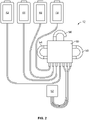
- Fig. 1 depicts an exemplary reusable or durable hardware component or processing device 10 that may be used in combination with a disposable or single use fluid flow circuit 12 ( Fig. 2 ) that includes (among other components) a fluid separation chamber according to the present disclosure.
- the illustrated processing device 10 includes associated pumps, valves, sensors, displays, and other apparatus for configuring and controlling flow of fluid through the fluid flow circuit 12.
- the processing device 10 may be directed by a controller integral with the processing device 10 that includes a programmable microprocessor to automatically control the operation of the pumps, valves, sensors, etc.
- the processing device 10 may also include wireless communication capabilities to enable the transfer of data from the processing device 10 to the quality management systems of the operator.
- the processing device 10 includes a user input and output touchscreen 14, a pump station or system including a first pump 16 (for pumping, e.g., whole blood), a second pump 18 (for pumping, e.g., plasma) and a third pump 20 (for pumping, e.g., additive solution), a centrifuge mounting station and drive unit 22 (which may be referred to herein as a "centrifuge” and is shown in greater detail in Fig. 3 ), and clamps 24a-c.
- the touchscreen 14 enables user interaction with the processing device 10, as well as the monitoring of procedure parameters, such as flow rates, container weights, pressures, etc.
- the pumps 16, 18, and 20 are illustrated as peristaltic pumps capable of receiving tubing or conduits of the fluid flow circuit 12 and moving fluid at various rates through the associated conduit dependent upon the procedure being performed.
- An exemplary centrifuge mounting station/drive unit is seen in U.S. Patent No. 8,075,468 (with reference to Figs. 26-28 ), which is hereby incorporated herein by reference.
- the clamps 24a-c are capable of opening and closing fluid paths through the tubing or conduits and may incorporate RF sealers in order to complete a heat seal of the tubing or conduit placed in the clamp to seal the tubing or conduit leading to a product container upon completion of a procedure.
- the processing device 10 also includes hangers 26a-d (which may each be associated with a weight scale) for suspending the various containers of the fluid flow circuit 12.
- the hangers 26a-d are shown as being mounted to a support 28, which is vertically translatable to improve the transportability of the processing device 10.
- An optical system (shown in greater detail in Fig. 4 ) comprising a light source 30 (which may be configured as a laser, for example) and a light detector 32 (which may be configured as a photodiode, for example) is associated with the centrifuge 22 for determining and controlling the location of an interface between separated fluid components within the centrifuge 22.
- An exemplary optical system is shown in U.S. Patent Application Publication No. 2019/0201916 .
- An optical sensor 34 is also provided to optically monitor one or more conduits leading into or out of the centrifuge 22.
- the face of the processing device 10 includes a nesting module 36 for seating a flow control cassette 50 ( Fig. 2 ) of the fluid flow circuit.
- the cassette nesting module 36 is configured to receive various disposable cassette designs so that the system may be used to perform different types of procedures.
- Embedded within the illustrated cassette nesting module 36 are four valves 38a-d (collectively referred to herein as being part of the "valve system" of the processing device 10) for opening and closing fluid flow paths within the flow control cassette 50, and three pressure sensors 40a-c capable of measuring the pressure at various locations of the fluid flow circuit 12.
- the illustrated fluid flow circuit 12 includes a plurality of containers 42, 44, 46, and 48, with a flow control cassette 50 and a fluid separation chamber 52 that is configured to be received in the centrifuge 22, all of which are interconnected by conduits or tubing segments, so as to permit continuous flow centrifugation.
- the flow control cassette 50 routes the fluid flow through three tubing loops 54, 56, 58, with each loop being positioned to engage a particular one of the pumps 16, 18, 20.
- the conduits or tubing may extend through the cassette 50, or the cassette 50 may have pre-formed fluid flow paths that direct the fluid flow.
- container 42 may be prefilled with additive solution
- container 44 may be filled with a fluid to be separated (e.g., whole blood) and connected to the fluid flow circuit 12 at the time of use
- container 46 may be an empty container for the receipt of a first component (e.g., red blood cells) separated from the fluid
- container 48 may be an empty container for the receipt of a second component (e.g., plasma) separated from the fluid.
- a container 44 shows a container 44 as a fluid source, it is within the scope of the present disclosure for the fluid source to be a living donor (in the case of blood separation).
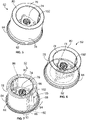
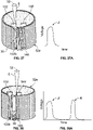
- FIGs. 5-7 illustrate an exemplary fluid separation chamber 52, with Fig. 5 showing the chamber 52, Fig. 6 showing interior details of the chamber 52, and
- Fig. 7 showing the position of various fluid components within the chamber 52 during an exemplary fluid separation procedure.
- the chamber 52 may be pre-formed in a desired shape and configuration by injection molding from a rigid plastic material, as shown and described in U.S. Patent No. 6,849,039 , which is hereby incorporated herein by reference.
- the controller of the processing device 10 is pre-programmed to automatically operate the system to perform one or more standard fluid separation or processing procedures selected by an operator by input to the touchscreen 14, and may be configured to be further programmed by the operator to perform additional separation and processing procedures.
- the controller commands the other components of the processing device 10 at pre-set settings for flow rates, centrifugation forces, etc., and may be further configured to receive input from the operator as to one or more parameters to override or supplement the pre-programmed settings.
- the controller may be pre-programmed to substantially automate a wide variety of procedures, including, but not limited to: red blood cell and plasma production from whole blood, buffy coat pooling, buffy coat separation into a platelet product, glycerol addition to red blood cells, red blood cell washing, platelet washing, and cryoprecipitate pooling and separation.
- Chambers according to the present are particularly well-suited for separating blood into two or more components (e.g., for collecting a red blood cell product and a plasma product or a red blood product, a plasma product, and a buffy coat product from a single unit of blood) and will be described in the context of blood separation.
- chambers according to the present disclosure may be used to separate other fluids, including both biological/bodily fluids and non-biological fluids.
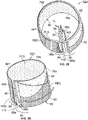
- the centrifuge 22 includes a centrifuge compartment 60 that may receive the other components of the centrifuge 22.
- the centrifuge compartment 60 may include a lid 62 that is opened to insert and remove a chamber 52 of the fluid flow circuit 12. During a separation procedure, the lid 62 may be closed with the chamber 52 positioned within the centrifuge compartment 60, as the chamber 52 is spun or rotated about an axis 64 under the power of an electric drive motor or rotor 66 of the centrifuge 22.
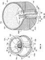
- the centrifuge 22 may include a carriage or support 68 that holds the chamber 52 and a yoke member 70.
- the yoke member 70 engages an umbilicus 72 of the fluid flow circuit 12, which extends between the chamber 52 and the cassette 50 ( Fig. 2 ).
- the yoke member 70 causes the umbilicus 72 to orbit around the chamber 52 at a "one-omega" rotational speed.
- the umbilicus 72 twists about its own axis as it orbits around the chamber 52.
- the twisting of the umbilicus 72 about its axis as it rotates at one-omega with the yoke member 70 imparts a "two-omega" rotation to the chamber 52, according to known design.
- the relative rotation of the yoke member 70 at a one-omega rotational speed and the chamber 52 at a two-omega rotational speed keeps the umbilicus 72 untwisted, avoiding the need for rotating seals.
- Fluid is introduced into the chamber 52 by the umbilicus 72, with the fluid being separated into a layer of less dense components (such as plasma) and a layer of more dense components (such as packed red blood cells) within the chamber 52 as a result of centrifugal forces as it rotates. As will be described in greater detail, additional component layers may arise between the layers of the most- and least-dense components.
- the optical system positioned within the centrifuge compartment 60 oversees separation of the fluid within the chamber 52. As shown in Fig. 4 , the optical system includes a light source 30 and a light detector 32, which is positioned and oriented to receive at least a portion of the light "L" emitted by the light source 30.
- the light source 30 and the light detector 32 are positioned on stationary surfaces of the centrifuge compartment 60 but, in other embodiments, one or both may be mounted to a movable component of the centrifuge 22 (e.g., to the yoke member 70, which rotates at a one-omega speed). It is also within the scope of the present disclosure for the optical system to be omitted, particularly when the chamber 52 is formed of an opaque material that does not transmit light therethrough.
- the orientation of the various components of the optical system depends at least in part on the particular configuration of the chamber 52, which will be described in greater detail herein.
- the light source 30 emits a light beam L (e.g., a laser light beam) through the separated fluid components within the chamber 52 (which may be formed of a material that substantially transmits the light or at least a particular wavelength of the light without absorbing it).
- a portion of the light L reaches the light detector 32, which transmits a signal to the controller that is indicative of the location of an interface between the separated fluid components.
- the controller determines that the interface is in the wrong location (which can affect the separation efficiency of the centrifuge 22 and/or the quality of the separated fluid components), then it can issue commands to the appropriate components of the processing device 10 to modify their operation so as to move the interface to the proper location.
- a central hub 74 of the chamber 52 coincides with the rotational axis 64 when the chamber 52 is mounted within the centrifuge 22.
- the central hub 74 includes a shaped receptacle that is suitable for receiving an end of the umbilicus 72 of the fluid flow circuit 12.
- a suitable receptacle and the manner in which the umbilicus 72 may cooperate with the receptacle to deliver fluid to and remove fluid from the chamber 52 are described in greater detail in U.S. Patent No. 8,075,468 .
- the illustrated chamber 52 has generally annular, radially spaced apart inner (low-G) and outer (high-G) walls 76 and 78 extending about the central hub 74.
- the body of the chamber 52 further includes a top end 80 and a bottom end 82.
- top and bottom are not intended to restrict the structure or orientation of the chamber 52 (e.g., Fig. 3 shows the bottom end 82 positioned above the top end 80), but rather are used to describe the various components of the chamber 52 in the orientation of Figs. 5-7 .
- a cover 84 is associated with the bottom end 82 (which is formed as an open surface), with the cover 84 comprising a simple flat part that can be easily welded or otherwise secured to the body of the chamber 52.
- the low- and high-G walls 74 and 76, the top end 80, and the cover 84 together define an enclosed, generally annular separation channel 86 ( Fig. 7 ), with the cover defining the bottom end of the separation channel 86.
- a plurality of radial walls extend from the central hub 74 to the separation channel 86, with two of the radial walls defining an inlet passage 88 opening into the separation channel 86 at an upstream end 90 of the separation channel 86.
- One of the radial walls 92 (which may define a surface of the inlet passage 88 and may be referred to as the "terminal wall") joins the high-G wall 78 and separates the upstream end 90 of the channel 86 from a downstream end 94.
- upstream end and downstream end when used in regard to regions of the separation channel 86, may refer to the first quarter or quadrant of the channel 86 (i.e., the region encompassing approximately 90° of the channel 86 on the side of the terminal wall 92 in which fluid enters the channel 86) and the last quarter or quadrant of the channel 86 (i.e., the region encompassing approximately 90° of the channel 86 on the side of the terminal wall 92 opposite the upstream end of the channel 86), respectively.
- the terms are most frequently used herein to refer to the position of various components or formations associated with the separation channel 86 (e.g., the inlet passage 88 opens into the channel 86 at the upstream end 90 of the channel 86) such that, in certain embodiments (depending on the configurations of the components described as being present at the upstream end 90 or downstream end 94 of the separation channel 86), the terms may refer to smaller regions of the separation channel 86, which may include (for example) the term "upstream end” referring to only the first 45° or 30° or less of the channel 86 and the term “downstream end” referring to only the last 45° or 30° or less of the channel 86.
- the radial walls further define low-G and high-G outlet passages 96 and 98, with the low-G outlet passage 96 opening into the channel 86 at the low-G wall 76 and the high-G outlet passage 98 opening into the channel 86 at the high-G wall 78.
- the illustrated outlet passages 96 and 98 are positioned at the downstream end 94 of the channel 86, such that the separated fluid components must traverse the entire length of the channel 86 before exiting the channel 86.
- At least one of the outlet passages 96, 98 is positioned upstream of the downstream end 94 of the channel 86, which may include an outlet passage (which would most typically be the low-G outlet passage 96) positioned adjacent to the inlet passage 88 at the upstream end 90 of the channel 86.
- Fluid flowed into the channel 86 separates into an optically dense layer RBC and a less optically dense layer PLS ( Fig. 7 ) as the chamber 52 is rotated about the rotational axis 64.
- the optically dense layer RBC forms as larger and/or heavier fluid particles move under the influence of centrifugal force toward the high-G wall 78.
- the optically dense layer RBC will typically include red blood cells (and, hence, may be referred to herein as the "RBC layer") but, depending on the speed at which the chamber 52 is rotated, other cellular components (e.g., larger white blood cells) may also be present in the RBC layer RBC.
- the less optically dense layer PLS will include plasma (and, hence, will be referred to herein as the "plasma layer”).
- plasma and, hence, will be referred to herein as the "plasma layer”
- other components e.g., platelets and smaller white blood cells and anticoagulant
- fluid introduced into the channel 86 via the inlet passage 88 will travel in a generally clockwise direction (in the orientation of Fig. 7 ) as the RBC layer RBC separates from the plasma layer PLS. Both layers travel along the length of the channel 86, from the upstream end 90 to the downstream end 94, with the plasma layer PLS moving along the low-G wall 76 and the RBC layer RBC moving along the high-G wall 78.
- the plasma layer PLS eventually exits the channel 86 via the low-G outlet passage 96 (which opens into the channel 86 at the low-G wall 76) and the RBC layer RBC exiting the channel 86 via the high-G outlet passage 98 (which opens into the channel 86 at the high-G wall 78).
- the interface INT As the two layers PLS and RBC separate, a transition forms therebetween, which may be referred to as the interface INT.
- the buffy coat (comprised primarily of white blood cells and platelets) will be located at the interface INT, with the buffy coat building up at the downstream end 94 of the channel 86 while the plasma layer PLS and RBC layer RBC exit the channel 86 (as can be seen in Fig. 7 ).
- flow conditions through the channel 86 may be changed (e.g., by drawing red blood cells back into the channel 86 via the high-G outlet passage 98) to force the buffy coat out of the channel 86 (typically via the low-G outlet passage 96) for collection.
- the location of the interface INT within the channel 86 can dynamically shift during blood processing, moving toward the low-G wall 76 or toward the high-G wall 78.
- the location of the interface INT is too high (that is, if it is too close to the low-G wall 76 and the low-G outlet passage 96)
- red blood cells can flow into the low-G outlet passage 96, potentially adversely affecting the purity of the separated plasma.
- the location of the interface INT is too low (that is, if it resides too far away from the low-G wall 76)
- the ideal or target position of the interface INT may be experimentally determined, which may vary depending on any of a number of factors (e.g., the configuration of the chamber 52, the rate at which the chamber 52 is rotated about the rotational axis 64, etc.).
- the illustrated processing device 10 includes an optical system and a controller, which may include an interface control module to monitor and, as necessary, change the position of the interface INT.
- the chamber 52 is formed with a ramp 100 ( Figs. 8-11 ) extending generally diagonally from the high-G wall 78 at an angle across at least a portion of the channel 86.
- the ramp 100 may be positioned at any of a number of locations within the channel 86, with the ramp 100 being positioned at the downstream end 94 of the channel 86 in the illustrated embodiment.
- the ramp 100 makes the interface INT between the RBC layer RBC and the plasma layer PLS more discernible for detection, displaying the RBC layer RBC, plasma layer PLS, and interface INT for viewing through a light-transmissive portion of the chamber 52.
- the ramp 100 and at least the portion of the chamber 52 angularly aligned with the ramp 100 may be formed of a light-transmissive material, although it may be advantageous for the entire chamber 52 to be formed of the same light-transmissive material.
- the light source 30 of the optical system is secured to a fixture or wall of the centrifuge compartment 60 and oriented to emit a light L that is directed toward the rotational axis 64 of the centrifuge 22, as shown in Fig. 4 .
- the light detector 32 is positioned at an angle with respect to the light source 30 (as in the illustrated embodiment)
- the light L emitted by the light source 30 must be redirected from its initial path before it will reach the light detector 32.
- the light L is redirected by a reflector that is associated with a light-transmissive portion of the low-G wall 76, as shown in Fig. 4 .
- the reflector may be a separate piece that is secured to the low-G wall 76 (e.g., by being bonded thereto) or may be integrally formed with the body of the chamber 52.
- the reflector is configured as described in U.S. Patent Application Publication No. 2019/0201916 , as a prismatic reflector 102 ( Figs. 12 and 13 ), which is formed of a light-transmissive material (e.g., a clear plastic material) and has outer and inner walls 104 and 106 and first and second end walls 108 and 110.
- the outer wall 104 is positioned against the low-G wall 76 of the chamber 52 and is oriented substantially perpendicular to the initial path of the light L from the light source 30. This allows light L from the light source 30 to enter into the prismatic reflector 102 via the outer wall 104 while continuing along its initial path.
- the light L continues through the prismatic reflector 102 along its initial path until it encounters the first end wall 108.
- the first end wall 108 is oriented at an angle (e.g., an approximately 45° angle) with respect to the outer wall 104 and the second end wall 110, causing the light to be redirected within the prismatic reflector 102 ( Fig. 13 ), rather than exiting the prismatic reflector 102 via the first end wall 108.
- the first end wall 108 directs the light L at an angle to its initial path (which may be an approximately 90° angle, directing it from a path toward the rotational axis 64 to a path that is generally parallel to the rotational axis 64) toward the second end wall 110.
- the first end wall 108 and the outer and inner walls 104 and 106 of the prismatic reflector 102 may be configured to transmit the redirected light L from the first end wall 108 to the second end wall 110 by total internal reflection.
- the second end wall 110 is oriented substantially perpendicular to the redirected path of the light L through the prismatic reflector 102, such that the light L will exit the prismatic reflector 102 via the second end wall 110, continuing along its redirected path.
- the second end wall 110 is roughened or textured or otherwise treated or conditioned to diffuse the light L as it exits the prismatic reflector 102, which may better ensure that the light L reaches the light detector 32 ( Fig. 4 ).
- the prismatic reflector 102 is angularly aligned with the ramp 100 ( Figs. 4 and 8-11 ), such that the light L from the light source 30 will only enter into the prismatic reflector 102 when the ramp 100 has been rotated into the path of the light L. At all other times (when the ramp 100 is not in the path of the light L), the light L will not reach the prismatic reflector 102 and, thus, will not reach the light detector 32. This is illustrated in Figs. 8-11 , which show the ramp 100 and prismatic reflector 102 as the chamber 52 is rotated about the rotational axis 64 (while the light source 30 remains in a fixed location).
- the ramp 100 and prismatic reflector 102 have not yet been rotated into the initial path of the light L from the light source 30. At this time, no light is transmitted to the light detector 32, such that the output voltage of the light detector 32 (i.e., the signal transmitted from the light detector 32 to the controller) is in a low- or zero-state.
- the ramp 100 Upon the ramp 100 first being rotated into the initial path of the light L from the light source 30 ( Fig. 9 ), the light L will pass through the ramp 100 and encounter the fluid components flowing through the channel 86, between the ramp 100 and the prismatic reflector 102. As shown in Fig. 9 , the ramp 100 is oriented such that the light L passing through the ramp 100 will first encounter the plasma layer PLS within the channel 86.
- At least a portion of the light L will pass through the plasma layer PLS to reach the prismatic reflector 102, which directs the transmitted light to the light detector 32. At this time, the output voltage of the light detector 32 will increase, compared to the low- or zero-stage of Fig. 8 .
- the light L will begin to encounter the RBC layer RBC in the channel 86, as shown in Fig. 11 .
- the RBC layer RBC will be positioned adjacent to the high-G wall 78 as it separates from the plasma layer PLS, such that the RBC layer RBC will not be displayed on the ramp 100 until the ramp 100 is spaced a greater distance away from the low-G wall 76 (i.e., toward the right end of the ramp 100 in the orientation of Figs. 8-11 ).
- the voltage output or signal from the light detector 32 When receiving less light L, the voltage output or signal from the light detector 32 will decrease to a lower level than when the light L was passing through only the plasma layer PLS in the channel 86.
- the light detector 32 may be generating a signal or voltage output that is approximately equal to its zero-state (as in Fig. 8 , when the light detector 32 is receiving no light L) or a signal or voltage output that is some degree less than the magnitude of the signal or voltage output generated while the light L encounters only the plasma layer PLS in the channel 86.
- the controller may be programmed and/or configured to recognize this lower level signal as representing the presence of the RBC layer RBC on the ramp 100 (and in the portion of the channel 94 being traversed by the light L) and treat this lower level signal as the end point of the elevated signal generated by the light detector 52 while light L passes through only the plasma layer PLS in the channel 86.
- the pulse width of the elevated signal from the light detector 32 to the controller (i.e., the time during which light L is traversing only the plasma layer PLS in the channel 86) is determined by the percentages of the ramp 100 that are occupied by the plasma layer PLS and the RBC layer RBC. Accordingly, a greater pulse width of the signal from the light detector 32 to the controller is associated with the plasma layer PLS occupying a larger portion of the ramp 100 and will be indicative of a thinner RBC layer RBC on the ramp 100.
- a signal from the light detector 32 to the controller having a narrower pulse width is associated with the plasma layer PLS occupying a smaller portion of the ramp 100 and will be indicative of a thicker RBC layer RBC on the ramp 100 (and in the channel 86).
- the controller may compare the pulse width of the signal to the pulse width generated during a calibration phase (during which the channel 86 is filled with a fluid that will transmit the light L), which corresponds to the pulse width when light L is transmitted to the light detector 32 over the entire width of the ramp 100. Comparing these two pulse widths will indicate the percentage of the ramp 100 that is occupied by the plasma layer PLS and by the RBC layer RBC, which information the controller may use to determine the location of the interface INT within the channel 86. As necessary, the controller may change flow conditions through the channel 86 (e.g., by increasing the rate at which the plasma layer PLS or the RBC layer RBC is conveyed out of the channel 86) to change the position of the interface INT within the channel 86.
- Figs. 14-33 show the fluid flow paths (i.e., the inlet passage, separation channel, and outlet passages) defined by different embodiments of chambers 52 according to the present disclosure, with the previously discussed RBC layer RBC, plasma layer PLS, and interface INT being labeled, along with the fluid to be separated being identified as "WB". While the various surfaces and formations of the chambers are not visible in Figs.
- the illustrated fluid flow paths are entirely defined by the corresponding chamber structures and surfaces described above (i.e., the illustrated inlet and outlet passages are defined by radial walls of the chamber, while the separation channel is defined by the low- and high-G walls, along with the ramp, if provided), as in Fig. 7 (which illustrates the chamber 52 creating the fluid flow path shown in Figs. 26 and 27 ).
- Fig. 7 which illustrates the chamber 52 creating the fluid flow path shown in Figs. 26 and 27 .
- Figs. 14-16 has a particularly configured ramp, rather than stating that the chamber 52 defining the fluid flow path shown in Figs. 14-16 has a particularly configured ramp).
- Figs. 14-33 may be annotated with reference numerals (with broken lead lines) representing the chamber surface defining a particular feature of the illustrated fluid flow path, rather than employing a new reference numeral for the fluid flow path feature arising from the chamber surface (e.g., identifying a fluid flow path feature defined by the ramp 100 of a chamber 52 as the ramp 100 instead of employing a unique identifier for that region of the fluid flow path itself).
- Figs. 14-33 are configured and function according to the preceding description of the chamber 52 of Figs. 5-7 , except where stated to the contrary. Additionally, it should be understood that, while different features may be presented separately in the fluid flow paths shown in Figs. 14-33 (e.g., Figs. 14-16 illustrate a fluid flow path resulting from a chamber having a modified low-G wall, while Figs. 26 and 27 show a fluid flow path resulting from a chamber having a modified inlet passage), the individual features of the various chambers defining those flow paths may be provided in various combinations (e.g., a chamber may incorporate the modified low-G wall of the chamber of Figs. 14-16 and the modified inlet passage of the chamber of Figs. 26 and 27 ) without departing from the scope of the present disclosure.
- the chambers 52 are configured to be compatible with the centrifuge drive mechanism of the well-known ALYX ® processing device sold by Fenwal, Inc. of Lake Zurich, III., which is an affiliate of Fresenius Kabi AG of Bad Homburg, Germany.
- the chamber 52 is configured to maximize the surface area of the separation channel 86 (i.e., maximize the surface area of the high-G wall 78).
- the high-G wall 78 is the separation surface area for the RBC layer RBC, such that maximizing the surface area of the high-G wall 78 will maximize the separation surface area for the RBC layer RBC. In the case of blood separation, maximizing the separation surface area for the RBC layer RBC will maximize the achievable hematocrit of the red blood cell product at a particular centrifuge rotation rate.
- the surface area of the high-G wall 78 is a function of the radius and height of the high-G wall 78, and it has been found that (in view of the geometric restrictions of the centrifuge drive mechanism of the ALYX ® processing device) a maximum surface area in the range of 138-140 cm 2 is possible for the high-G wall 78 of a chamber 52 configured to be compatible with the centrifuge drive mechanism of the ALYX ® processing device.
- a 1° outward taper (away from the central axis of the chamber 52, from the top end 80 to the bottom end 82) may be incorporated into the high-G wall 78, while a 1° inward taper (toward the central axis of the chamber 52, from the top end 80 to the bottom end 82) may be incorporated into the low-G wall 76.
- the high-G wall 78 will have (in one embodiment) a height of 6.08 cm and a radius of 4 cm at the top end 80, resulting in a radius of 4.11 cm at the bottom end 82.
- the particular configuration of the low-G walls of the chambers of Figs. 14-27 may vary, such that the radius of the low-G wall at the top end 80 and the bottom end 82 may vary from chamber to chamber.
- the tapers of the low- and high-G walls (when present) will result in the separation channel 86 having a greater width at the bottom end 82 than at the top end 80.
- a greater channel width allows for improved fluid separation, such that the outlet passages 96, 96a and 98, 98a, 98b of all of the chambers 52 of Figs. 14-33 are shown as opening into the separation channel 86 at the bottom end 82.
- FIG. 14-27 Another common feature of the fluid flow paths shown in Figs. 14-27 (though not the fluid flow path of Figs. 28-33 ) is that, in all cases, the outlet passages 96, 96a and 98, 98a defined by the chambers 52 are positioned at the downstream end 94 of the separation channel 86.
- This is different from the configuration of a conventional rigid chamber (e.g., as presented in U.S. Patent Application Publication No. 2019/0201916 ) in which the low-G outlet passage opens into the separation channel at or adjacent to the upstream end of the channel (similar to the inlet passage).
- a ramp 100 is positioned at the downstream end 94 of the separation channel 86.
- This chamber configuration is different from the configuration of current rigid chambers employing a ramp (e.g., as presented in U.S. Patent Application Publication No. 2019/0201916 ), which positions the ramp at or adjacent to the upstream end of the separation channel (on account of the low-G outlet passage being positioned at or adjacent to the upstream end of the channel).
- the high-G wall 78 has a uniform (or at least substantially uniform) radius, while the low-G wall 76 has a non-uniform radius at the bottom end 82 resulting from a formation 112 referred to herein as an "air drain taper.”
- the air drain taper 112 has a width that increases from the upstream end 90 of the separation channel 86 to the downstream end 94, which has the effect of decreasing the radius of the low-G wall 76 at the bottom end 82 from the upstream end 90 of the channel 86 to the downstream end 94, with a maximum radius at the upstream end 90 and a minimum radius at the downstream end 94 (where the low-G outlet passage 96 is positioned).
- the air drain taper 112 creates a "lowest-G" point at the bottom end 82 along the entire circumference of the separation channel 86, which is where air will tend to gather and move, thus increasing the amount of air that exits the channel 86 via the low-G outlet passage 96 during priming of the fluid flow path.
- An air drain taper 112 is considered to be particularly advantageous for chambers with large fluid gaps, as it enables just a small portion of the chamber to be tapered for improved air flow.
- the width of the air drain taper 112 increases gradually and uniformly from the upstream end 90 of the separation channel 86 to the downstream end 94.
- the air drain taper 112 may be understood as having an inner radius or surface shaped as a uniform or Archimedean spiral.
- the spiral shape of the inner radius or surface of the air drain taper 112 makes 94% of a full revolution, with a pitch (offset) of 0.16 cm, resulting in a maximum radius of 3.55 cm (at the upstream end 90 of the separation channel 86) and a minimum radius of 3.4 cm (at the downstream end 94 of the channel 86).
- pitches or offsets may be employed, with the preferred pitch or offset depending on various considerations, including the resulting degree of air flow and the resulting volume of the separation channel 86 at the bottom end 82.
- the inner radius or surface of the air drain taper 112 may follow a different path, such as the path of a non-uniform spiral.
- the height of the air drain taper 112 may vary without departing from the scope of the present disclosure. In one embodiment, it was found that a uniform height of 0.2 cm produced effective air flow. This height is approximately 4.2% of the height of the low-G wall 76 when the chamber 52a is configured to be compatible with the centrifuge drive mechanism of the ALYX ® processing device, though it is believed that the actual height of the air drain taper 112 itself (independent of the height of the associated low-G wall 76) has a greater effect on air flow.
- Figs. 14-16 illustrate an air drain taper 112 having a uniform height, the height of the air drain taper 112 may change (typically increasing) from the upstream end 90 of the separation channel 86 to the downstream end 94.
- the transition between the low-G wall 76 and the air drain taper 112 is shown as a step, though it should be understood that there may instead be a smooth or gradual transition between the low-G wall 76 and the air drain taper 112. While it is not believed that providing a smooth or gradual transition will significantly affect air flow compared to a step, a smooth or gradual transition may improve the moldability of the chamber 52a.
- the air drain taper 112 effectively increases the width of the separation channel 86 at the bottom end 82 from the upstream end 90 to the downstream end 94.
- This is in contrast to known spiral-shaped fluid flow paths (e.g., ones of the type described in U.S. Patent No. 9,327,296 ) in which a low-G wall and a high-G wall both follow a spiral path from the upstream end of the separation channel to the downstream end (resulting in a uniform channel width) and known fluid separation chambers in which the width of a separation channel decreases from the upstream end to the downstream end.
- the chamber 52a of Figs. 14-16 is also illustrated as defining a region 114 (which may be referred to as a "cell settling well") at the downstream end 94 of the separation channel 86.
- the bottom end 116 of the ramp 100 is entirely spaced from the bottom end 82 of the separation channel 86, with the cell settling well 114 providing a flow path extending through that space to allow the separated fluid components to reach the outlet passages 96 and 98.
- the surface of the cell settling well 114 closest to the center of the chamber is defined by a generally planar, radially inward departure or extension 118 of the low-G wall 76 from its standard radius ( Figs. 15 and 16 ), which effectively increases the width of the cell settling well 114.
- this extension 118 has the same radius as the air drain taper 112 at the downstream end of the extension 118.
- the extension 118 effectively increases the width of the separation channel 86 at the cell settling well 114, which increases the fluid thickness and allows the plasma layer PLS to be larger at the cell settling well 114 (with the thickness of the RBC layer RBC remaining the same). In the case of blood separation, this allows the cellular content in the buffy coat/interface INT and the RBC layer RBC to be farther from the low-G outlet passage 96 at the cell settling well 114 (which is positioned directly adjacent to the openings of the outlet passages 96 and 98 into the separation channel 86).
- the entirety of the low-G wall 76a has a radius that decreases at each axial position from a maximum radius at the upstream end 90 of the separation channel 86 to a minimum radius at the downstream end 94.
- the low-G wall will not have a uniform radius along its height, instead having a greater radius at the top end of the chamber 52 than at the bottom end (for example).
- the low-G wall 76 may not have a uniform radius along its height (due to manufacturing considerations), the low-G wall 76 has a uniform radius at each axial position.
- the low-G wall 76 of the chamber 52a of Figs. 14-16 has a uniform radius at the top end 80 of the chamber 52a and a uniform radius at the bottom end 82 of the chamber 52a, though the radii of the low-G wall 76 at the top and bottom ends 80 and 82 may be different from each other.
- the low-G wall 76a has a radius that decreases at each axial position from the upstream end 90 of the separation channel 86 to the downstream end 94 of the separation channel 86.
- the top end of the low-G wall 76a of the chamber 52b of Figs. 17-19 has a radius that decreases from a maximum radius at the upstream end 90 of the separation channel 86 (which is 3.8 cm in an exemplary embodiment) to a minimum radius at the downstream end 94 (which is 3.65 cm in the exemplary embodiment).
- the 17-19 also has a bottom end with a radius that decreases from a maximum radius at the upstream end 90 of the channel 86 to a minimum radius at the downstream end 94, though (due to manufacturing considerations) the maximum radii at the top and bottom ends may be different from each other and/or the minimum radii at the top and bottom may be different from each other.
- the radius of the top end of the low-G wall 76a of Figs. 17-19 may be different from the radius at the bottom end at any given position along the length or circumference of the separation channel 86 due to manufacturing considerations (as in the embodiment of Figs.
- the radius of the low-G wall 76a at that axial position will be also different at different positions along the length or circumference of the separation channel 86.
- the chamber 52a of Figs. 14-16 which (as explained above) has a low-G wall 76 with a uniform radius at each axial position (i.e., a radius that may change along the height of the low-G wall 76 due to manufacturing considerations, but does not change at any given axial position along the length or circumference of the separation channel 86).
- an air drain taper may be advantageous for chambers with large fluid gaps, but the chamber 52b of Figs. 17-19 has a smaller fluid gap than the chamber 52a of Figs. 14-16 .
- the separation channel 86 of the chamber 52b of Figs. 17-19 has a width of approximately 0.2 cm at the top end 80 and a width of approximately 0.35 cm at the bottom end 82
- the channel 86 of the chamber 52a of Figs. 14-16 has a width of approximately 0.4 cm at the top end 80 and a width of approximately 0.57 cm at the bottom end 82.
- the width of the top end 80 of the separation channel 86 at the upstream end 90 could be further decreased, though doing so may present manufacturing challenges without improving fluid separation. Due to the relatively small fluid gap, it is practicable for the entire low-G wall 76a of the chamber 52b of Figs. 17-19 to having a radius that decreases from the upstream end 90 of the separation channel 86 to the downstream end 94 at each axial position, as the chamber volume does not come undesirably large. Limiting the volume of the separation channel 86 is particularly important when the available volume of fluid to be separated is limited (e.g., when only one unit of blood is available to be separated), as less fluid is required to fill the channel 86. A smaller volume also makes it easier to prime the separation channel 86 at the beginning of a procedure and to flush the channel 86 at the end of (or even during) a procedure.
- the exact configuration of the low-G wall 76a of the chamber 52b of Figs. 17-19 may vary without departing from the scope of the present disclosure.
- the radius of the low-G wall 76a at each axial position decreases gradually and uniformly from the upstream end 90 of the separation channel 86 to the downstream end 94.
- the low-G wall 76a may be understood as having the shape of a uniform or Archimedean spiral at each axial position.
- the top end of the low-G wall 76a may uniformly spiral from a maximum radius of 3.8 cm at the upstream end 90 of the separation channel 86 to a minimum radius of 3.65 cm at the downstream end 94 of the channel 86.
- Other pitches or offsets may be employed, with the preferred pitch or offset depending on the relative importance placed on the degree of cell settling (which is improved by a larger pitch or offset) vs. the total volume of the separation channel 86 (which is reduced by a smaller pitch or offset).
- the shape of the low-G wall 76a may follow a different path, such as the path of a non-uniform spiral.
- the decreasing radius of the low-G wall 76a effectively increases the width of the separation channel 86 from the upstream end 90 to the downstream end 94 at each axial position. As noted above, this is in contrast to spiral-shaped fluid flow paths (e.g., ones of the type described in U.S. Patent No.
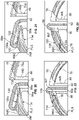
- FIG. 20 highlights the configuration of the bottom end 120 of the ramp 100a of Figs. 17-19
- Fig. 22 highlights the configuration of the bottom end 116 of the ramp 100 of Figs. 14-16
- Fig. 21 highlights the configuration of the top end 122 of the ramp 100a of Figs. 17-19
- Fig. 23 highlights the configuration of the top end 124 of the ramp 100 of Figs. 14-16 .
- the top and bottom ends 122 and 120 of the ramp 100a of Figs. 17-19 are shown together in Fig. 24 , with the top and bottom ends 124 and 116 of the ramp 100 of Figs. 14-16 being shown together in Fig. 25 .
- the ramp 100 is positioned at the downstream end 94 of the separation channel 86, extending diagonally from a first position 126 of the high-G wall 78 (which position may be referred to as the "upstream end” of the ramp 100) to a second position 128 (downstream of the first position 126) of the low-G wall 76 (which position may be referred to as the "downstream end” of the ramp 100).
- the outlet passages 96 and 98 open into the separation channel 86 at the downstream end 126 of the ramp 100 (at the bottom end 82 of the channel 86), with the bottom end 116 of the ramp 100 being spaced away from (i.e., positioned above) the bottom end 82 of the channel 86.
- the cell settling well 114 provides a flow path in the space between the bottom end 116 of the ramp 100 and the bottom end 82 of the separation channel 86.
- the ramp 100a of Figs. 17-19 is positioned at the downstream end 94 of the separation channel 86, extending diagonally from a first position 130 of the high-G wall 78 (which position may be referred to as the "upstream end” of the ramp 100a) to a second position 132 (downstream of the first position 130) of the low-G wall 76 (which position may be referred to as the "downstream end” of the ramp 100a).
- the downstream end 132 of the ramp 100a of Figs. 17-19 is positioned much farther downstream than the downstream end 128 of the ramp 100 of Figs. 14-16 .
- the ramp 100a of Figs. 17-19 has a greater length (along the circumference of the separation channel 86) than the ramp 100 of Figs. 14-16 .
- the bottom end 116 of the ramp 100 of Figs. 14-16 has a length of approximately 0.87 cm
- the bottom end 120 of the ramp 100a of Figs. 17-19 has a length of approximately 1.43 cm.
- the top end 124 of the ramp 100 of Figs. 14-16 has a length of approximately 0.65 cm
- 17-19 has a length of approximately 1.06 cm.
- the bottom end 82 of the separation channel 86 may have a greater width than the top end 80 of the channel 86 (due to manufacturing considerations), which is why the bottom end of each ramp may have a greater length than the top end of that ramp.
- the ramp 100a of Figs. 17-19 In addition to the ramp 100a of Figs. 17-19 being longer than the ramp 100 of Figs. 14-16 , the ramp 100a of Figs. 17-19 also extends across the separation channel 86 at a shallower angle. In the above-described exemplary embodiment, the top end 124 of the ramp 100 of Figs.
- both the top and bottom ends 122 and 120 of the ramp 100a of Figs. 17-19 extend across the separation channel 86 at an angle "R" of approximately 50.43° (relative to a radial line from the central axis of the chamber 52b to the upstream end of the ramp 100a), as shown in Fig. 24 .
- a shallower angle i.e., a greater angle relative to a radial line from the central axis of the chamber to the upstream end of the ramp
- the shallower angle of the ramp 100a of Figs. 17-19 does allow for an increased length.
- the angles T and B of the ramp 100 of Figs. 14-16 are similar to the angle R of the ramp 100a of Figs. 17-19 , such that the difference in ramp angle does not entirely account for the difference in lengths of the ramps 100 and 100a.
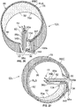
- the chamber 52b of Figs. 17-19 defines an additional feature 134 (referred to herein as a "low-G recess feature") that creates more space for the ramp 100a to have a greater length.
- the low-G recess feature 134 is defined by the chamber 52b of Figs. 17-19 at the downstream end 94 of the separation channel 86.
- the low-G recess feature 134 is essentially a generally planar, radially inward departure or extension of the low-G wall 76a from its standard radius (similar to the cell settling well 114 of Figs. 14-16 ), extending from a first end 136 to a downstream second end 138 at which the low-G wall 76a has a smaller radius.
- the low-G recess feature 134 is instead positioned radially inwardly of the ramp 100a, with a portion of the low-G recess feature 134 extending along the entire height of the separation channel 86.
- the entirety of the low-G recess feature 134 extends along the entire height of the separation channel 86, except at its second end 138, where a bottom end 140 of the low-G recess feature 134 is spaced a small distance from (above) the bottom end 82 of the separation channel 86 ( Fig. 19 ).
- This small gap or space between the bottom end 140 of the low-G recess feature 134 and the bottom end 82 of the separation channel 86 allows fluid flow beneath the second end 138 of the low-G recess feature 134, to the low-G outlet passage 96a.
- the second end 138 of the low-G recess feature 134 may coincide with the downstream end 132 of the ramp 100a, with the position of the second end 138 of the low-G recess feature 134 (which is positioned at an especially small radial position) being primarily responsible for the increased length of the ramp 100a.
- the controller of a processing device 10 may determine the position of the interface INT within the separation channel 86 by assessing the pulse width of a signal from the light detector 32 of an optical system. It should be clear that, by providing a longer ramp that extends across the separation channel 86 at a shallower angle (as in the embodiment of Figs. 17-19 ), a wider pulse width will be produced at any given position of the interface INT, which may be advantageous for certain interface position control circumstances. Additionally, having the ramp 100a closer to the low-G outlet passage 96a allows for the position of the interface INT to be monitored closer to the low-G outlet passage 96a, which may be advantageous for separation quality.
- the buffy coat may form an inconsistent interface INT, in which case measuring the interface position closer to the low-G outlet passage 96a helps to ensure that the interface INT is maintained at a position sufficiently far from the low-G outlet passage 96a to allow for clean plasma collection.
- FIG. 14-16 Another difference between the ramp 100 of Figs. 14-16 and the ramp 100a of Figs. 17-19 is that the top and bottom ends 122 and 120 of the ramp 100a of Figs. 17-19 are positioned at the same approximate circumferential position (as shown in Fig. 24 ), whereas the top and bottom ends 124 and 116 of the ramp 100 of Figs. 14-16 are positioned at much different circumferential positions (as shown in Fig. 25 ). In the embodiment illustrated in Fig.
- the top end 122 of the ramp 100a is oriented at an angle "C" of approximately 76.04° from a "12:00" position of the chamber 52b, while the bottom end 120 is oriented at an angle "D" of approximately 75.61° from the "12:00” position.
- the top end 124 of the ramp 100 is oriented at an angle "E” of approximately 86.03° from the "12:00" position of the chamber 52a, while the bottom end 116 is oriented at an angle "F” of approximately 70.89° from the "12:00” position.
- This configuration of the ramp 100 of Figs. 14-16 arises from maintaining the same approximate angle at all points from the top end 124 of the ramp 100 to the bottom end 116 of the ramp 100 with respect to a radial line extending from the central axis of the chamber 52a.
- the ramp 100 of Figs. 14-16 and the ramp 100a of Figs. 17-19 is the position of the high-G outlet passage with respect to the ramp.
- the high-G outlet passage 98 (along with the low-G outlet passage 96) opens into the separation channel 86 downstream of the ramp 100.
- the high-G outlet passage 98a opens into the separation channel 86 at the upstream end 130 of the ramp 100a ( Fig. 21 ), with the high-G outlet passage 98a extending radially outwardly and then downstream and past the downstream end 132 of the ramp 100a.
- Such a configuration provides additional space between the positions at which the two outlet passages 96a and 98a open into the separation channel 86, which is advantageous in reducing the risk that turbulence at the opening of either outlet passage affects fluid flow to the other outlet passage.
- the chamber of Figs. 17-19 defines a second feature 142 (in addition to the low-G recess feature 134) configured to improve the purity of the plasma layer PLS exiting the separation channel 86 via the low-G outlet passage 96a. Similar to the low-G recess feature 134, this second feature 142 (which may be referred to as a "fluid velocity reduction feature") is defined by the chamber at the downstream end 94 of the separation channel 86, adjacent to the ramp 100a.
- the fluid velocity reduction feature 142 is instead positioned beneath a portion of the ramp 100a, similar to the cell settling well 114 of Figs. 14-16 . More particularly, the fluid velocity reduction feature 142 is a fluid flow path (which may be generally block-shaped, in an exemplary embodiment) defined by the chamber in the space between the bottom end 120 of the ramp 100a and the bottom end 82a of the separation channel 86.
- the fluid velocity reduction feature 142 is, thus, similar to the cell settling well 114 in that it allows for fluid flow in the space between the ramp 100a and the bottom end 82 of the separation channel 86. However, the fluid velocity reduction feature 142 is different from the cell settling well 114 in the degree of fluid flow that is allowed. In particular, whereas the bottom end 116 of the ramp 100 of Figs. 14-16 is entirely spaced from the bottom end 82 of the separation channel 86 (such that the cell settling well 114 provides a fluid flow path beneath the entire ramp 100), only a portion of the ramp 100a of Figs. 17-19 is spaced from the bottom end 82 of the channel 86.
- a radially outer surface 144 of the fluid velocity feature 142 may be defined by a generally planar extension at the bottom of the ramp 100a ( Fig. 19 ), which further limits the thickness of a separated fluid component that may flow through the fluid velocity feature 142.
- the fluid velocity reduction feature 142 provides a narrower fluid flow path, allowing less fluid flow than the cell settling well 114.
- the fluid velocity reduction feature 142 may be configured to allow only the plasma layer PLS to flow beneath the ramp 100a (to reach the low-G outlet passage 96a), whereas the cell settling well 114 allows for all of the separated fluid components to flow beneath the ramp 100 (to reach the two outlet passages 96 and 98).
- the region of the channel 86 directly adjacent to the opening of the low-G outlet passage 96a (which comprises the flow path defined beneath the second end 138 of the low-G recess feature 134) would be relatively constricted, increasing the flow rate of fluid through that region.
- This hypothetical constricted region is illustrated in Fig. 19 as the portion of the channel 86 to the left of line "V".
- the width of the region of the channel 86 directly adjacent to the opening of the low-G outlet passage 96a is thus increased (to encompass the regions to the left and right of line V), reducing the flow rate of fluid through that region and reducing the likelihood of a substance from the interface INT (e.g., platelets, in the case of blood separation) reaching the low-G outlet passage 96a.
- a substance from the interface INT e.g., platelets, in the case of blood separation
- the two features may be provided separately.
- Figs. 26 and 27 illustrate a chamber 52c that is similar to the one of Figs. 17-19 , with the one distinction being the position at which the inlet passage 88a opens into the separation channel 86.
- the inlet passage 88 opens into the separation channel 86 at the upstream end 90 of the channel 86 and at the bottom end 82 of the channel 86.
- the inlet passage 88a (while still opening into the separation channel 86 at the upstream end 90) opens into the channel 86 at the top end 80 of the channel 86.
- the fluid and separated fluid components may favor the bottom half of the channel 86 because the convection pathway within the fluid path is located along the bottom end 82 of the channel 86 (i.e., there is no flow present to push the fluid or fluid components toward the top half of the channel 86).
- Reconfiguring the inlet passage 88a to open into the separation channel 86 at the top end 80 of the channel 86 creates a convective flow pathway from the top end 80 of the channel 86 (at the inlet passage 88a) to the bottom end 82 of the channel 86 (at the outlet passages 96a and 98a).
- Figs. 28-33 illustrate another exemplary fluid separation chamber 52d embodying aspects of the present disclosure.
- the chamber 52d of Figs. 28-33 is similar in some respects to the previously described fluid separation chambers and different in other respects.
- the chamber 52d includes a central hub 74 coinciding with a rotational axis, with a plurality of radial walls extending from the central hub 74 to a single-stage separation channel 86 defined between a generally annular low-G wall 76b and a generally annular high-G wall 78a.
- the radial walls of the chamber 52d define a terminal wall 92 separating an upstream end 90 of the separation channel 86 from a downstream end 94.
- the low-G wall 76b of the chamber 52d has a radius that decreases at each axial position from a maximum radius at the upstream end 90 of the separation channel 86 to a minimum radius at the downstream end 94, similar to the chamber 52b of Figs. 17-19 .
- the high-G wall 78a also has a radius that decreases at each axial position from a maximum radius at the upstream end 90 of the separation channel 86 to a minimum radius at the downstream end 94.
- the curvatures of the low-G wall 76b and the high-G wall 78a may differ, in which case the width of the separation channel 86 may vary from the upstream end 90 to the downstream end 94.
- the low-G wall 76b and the high-G wall 78a may have similar curvatures, with the width of the separation channel 86 remaining uniform (or at least substantially uniform) from the upstream end 90 of the channel 86 to the downstream end 94 of the channel 86 at each axial position.
- the exact configurations of the low-G and high-G walls 76b and 78a of the chamber 52d of Figs. 28-33 may vary, it may be advantageous to maximize the surface area of the high-G wall 78a because it is the separation surface area for the RBC layer RBC, such that maximizing the surface area of the high-G wall 78a will maximize the separation surface area for the RBC layer RBC.
- maximizing the separation surface area for the RBC layer RBC will maximize the achievable hematocrit of the red blood cell product at a particular centrifuge rotation rate.
- the surface area of the high-G wall 78a is a function of the radius and height of the high-G wall 78a, along with the curvature of the high-G wall 78a from the upstream end 90 of the separation channel 86 to the downstream end 94.
- the separation channel 86 at its upstream end 90, has a height of approximately 6.1 cm, with a high-G wall radius of approximately 4.1 cm at the bottom end 82 and 4.0 cm at the top end 80 (on account of the above-described 1° taper away from the central axis of the chamber 52d, from the top end 80 to the bottom end 82).
- the surface area of such a high-G wall 78a may be approximately 141.6 cm 2 , which may be near the maximum possible for a chamber 52d configured to be compatible with the centrifuge drive mechanism of the ALYX ® processing device.
- the low-G wall 76b in the above-described exemplary embodiment (in which the high-G wall 78a has a radius of approximately 4.1 cm at the bottom end 82 and 4.0 cm at the top end 80), at the upstream end 90 of the separation channel 86, it may have a radius of approximately 3.6 cm at the bottom end 82 and 3.7 cm at the top end 80 (on account of the above-described 1° inward taper toward the central axis of the chamber 52d, from the top end 80 to the bottom end 82).
- the radii of the low-G wall 76b and the high-G wall 78a at any downstream position depends on the particular curvature of the walls 76b and 78a.
- the radius of each of the low-G wall 76b and the high-G wall 78a decreases gradually and uniformly from the upstream end 90 of the separation channel 86 to the downstream end 94 at each axial position.
- the low-G wall 76b and the high-G wall 78a may be understood as each having the shape of a uniform or Archimedean spiral at each axial position, as best shown in Fig. 30 .
- Fig. 30 As also can be seen in Fig.
- the radial position of the RBC layer RBC remains substantially uniform from the upstream end 90 of the separation channel 86 to the downstream end 94 of the channel 86. If the separation channel 86 had a uniform radius, the thickness of the RBC layer RBC would remain uniform or at least substantially uniform from the upstream end 90 of the channel 86 to the downstream end 94.
- the RBC layer RBC will instead have a greater thickness at the upstream end 90 of the channel 86 than at the downstream end 94, as shown in Fig. 30 .
- the thickness of the plasma layer PLS will be greater at the downstream end 94 than at the upstream end 90 (also on account of the decreasing radius of the channel 86 from the upstream end 90 to the downstream end 94). If the chamber 52d is rotated at a relatively low rate (which is effective to separate a fluid into two layers), the thickness of the plasma layer PLS will gradually increase from the upstream end 90 of the separation channel 86 to the downstream end 94.
- the thickness of the plasma layer PLS may not uniformly increase from the upstream end 90 of the separation channel 86 to the downstream end 94, but may rather increase, before temporarily decreasing and then increasing again (as shown in Fig. 30 ). This is due to the thickness of the interface INT increasing and then decreasing toward the downstream end 94 of the separation channel 86, with the change in thickness of the interface INT being inversely related to the change in thickness of the plasma layer PLS.
- the change in thickness or taper of the plasma layer PLS promotes flow toward the low-G outlet passage 96, which is positioned at the downstream end 94 of the separation channel 86.
- providing a separation channel 86 with a spiral shape has a significant benefit of increasing the volume of plasma that may be extracted, which may lead to shorter procedure times.
- One reason for this is that, at a greater RBC layer RBC thickness (which occurs when the RBC layer RBC has a greater hematocrit, in the case of blood separation), the interface between the separated components will be closer to the low-G wall 76b, particularly at the upstream end 90 of a separation channel 86 having a radius that decreases from its upstream end 90 to its downstream end 94.
- a separation channel 86 having a radius that decreases from its upstream end 90 to its downstream end 94 may enhance plasma separation efficiency
- the risk of platelets being pulled from the interface INT into the low-G outlet passage 96 may also increase.
- One reason for this is due to the separation surface for platelets being the surface of the red blood cell bed.
- increasing or maximizing the hematocrit of the RBC layer RBC (which makes the RBC layer RBC thicker) will move the red blood cell bed closer to the low-G wall 76b, which decreases the separation surface area for platelets (due to the decreased radius of the red blood cell bed).
- the separation channel 86 a significant factor in the preferred configuration of the separation channel 86 (including the manner and degree in which its radius decreases from its upstream end 90 to its downstream end 94) will be whether plasma purity or separation efficiency is prioritized.
- plasma purity it may be advantageous to employ a smaller or more gentle spiral (i.e., one resulting in a smaller difference between the radii of the separation channel 86 at the upstream and downstream ends 90 and 94).
- a larger spiral i.e., one resulting in a greater difference between the radii of the separation channel 86 at the upstream and downstream ends 90 and 94 of the channel 86) may be advantageous.
- a larger spiral will tend to allow air to more readily exit the separation channel 86 via the low-G outlet passage 96 during priming, such that a larger spiral may be preferred when air removal is a higher priority.
- a reduced separation surface area for platelets will lead to fewer platelet sedimentation issues when processing smaller amounts of blood, such that a larger spiral may be more suitable for processing a single unit of blood, rather than an apheresis setting in which a much greater volume of blood is to be processed.
- the chamber 52d of Figs. 28-33 also differs from the embodiments of Figs. 5-27 with regard to the location of the high-G outlet passage 98b.
- the high-G outlet passage opens into the separation channel at the downstream end of the channel
- the high-G outlet 98b of the chamber 52d of Figs. 28-33 opens into the channel 86 at the upstream end 90.
- the chamber 52d of Figs. 28-33 is shown with a spiral-shaped separation channel 86 and a high-G outlet passage 98b that opens into the channel 86 at the upstream end 90, it should be understood that these features may be practiced separately.
- the inlet passage 88a also opens into the separation channel 86 at the upstream end 90, so care must be taken to ensure that fluid entering the channel 86 via the inlet passage 88a does not flow directly into the high-G outlet passage 98b without separating. In the illustrated embodiment, this direct flow from the inlet passage 88a to the high-G outlet passage 98b is avoided by configuring the inlet passage 88a to open into the separation channel 86 at the top end 80 of the channel 86, while the high-G outlet passage 98b opens into the channel 86 at the bottom end 82.
- FIG. 29 shows the general direction of flow of the RBC layer RBC from the time it enters the separation channel 86 (as part of an unseparated fluid) via the inlet passage 88a to the time it exits the channel 86 via the high-G outlet passage 98b.
- fluid enters the upstream end 90 of the separation channel 86 via the inlet passage 88a and begins to move toward the low-G outlet passage 96 at the downstream end 94 of the channel 86.
- the fluid separates into two or more component parts as it moves through the separation channel 86, with the RBC layer RBC reversing direction at some point within the channel 86 and moving in a general direction from the downstream end 94 of the channel 86 toward the upstream end 90.
- Figs. 28-33 show at least a portion of the RBC layer RBC moving to the downstream end 94 of the separation channel 86 before reversing direction, but it should be understood that the RBC layer RBC may not necessarily reach the downstream end 94 of the channel 86 before reversing direction.
- the chamber 52d of Figs. 28-33 may also include a ramp 100b.
- the ramp 100b is oriented at a 45° angle "P" with respect to the radius line of the high-G wall 78a (as shown in Fig. 33 ), with a bottom end 116 that is entirely spaced from the bottom end 82 of the separation channel 86.
- ramp orientations and configurations may be employed, with the consequences of different ramp orientations and configurations being described above in greater detail.
- a cell settling well 114a ( Figs. 31 and 32 ) allows for fluid flow through the gap to further improve the purity of the plasma layer PLS exiting the separation channel 86 via the low-G outlet passage 96.
- the cell settling well 114a increases the channel area available for flow near the low-G outlet passage 96, thereby reducing the fluid velocity in the vicinity of the low-G outlet passage 96, which reduces the likelihood of platelets being pulled into the low-G outlet passage 96 (in the case of blood separation).
- Fig. 32 shows the additional flow area provided by the cell settling well 114a (as represented by the portion of the channel 86 to the left of line "V"), which maintains the consistent high-G to low-G fluid thickness of the separation channel 86 in the vicinity of the low-G outlet passage 96 to prevent an increase in flow rate.
- While the formation 114a allowing for fluid flow through the gap between the bottom end 116 of the ramp 100b and the bottom end 82 of the separation channel 86 is referred to herein as a "cell settling well,” it will be seen that it has similarities to both the cell settling well 114 of the chamber 52a of Figs. 14-16 and the fluid velocity reduction feature 142 of the chamber 52b of Figs. 17-19 (such that it could alternatively be referred to as a "fluid velocity reduction feature" or something else entirely).
- the cell settling well 114a of Figs. 31 and 32 is similar to the cell settling well 114 of Figs.
- the cell settling well 114a of Figs. 31 and 32 is similar to the fluid velocity reduction feature 142 to the extent that it is relatively short in the axial or vertical direction, whereas the cell settling well 114 of Figs. 14-16 is taller in the axial or vertical direction (e.g., on the order of one quarter of the height of the separation channel 86).
- the greater height of the cell settling well 114 of Figs. 14-16 allows for a greater degree of cell settling, though the fluid velocity reduction feature 142 and the shorter cell settling well 114a may also induce some cell settling.
- Figs. 34-38 illustrate another exemplary fluid separation chamber 52e and the position of various fluid components within a fluid separation channel 86 defined by the fluid separation chamber 52e.
- the chamber 52e and the fluid separation channel 86 it defines may be understood as a variation of the fluid separation chamber 52d and fluid separation channel 86 of Figs. 28-33 , so the aspects and features of the chamber 52e of Figs. 34-38 that are common to both chambers 52d and 52e will not be described in detail. Additionally, it should be understood that the techniques illustrated in Figs. 34-38 and described below may be applied to any of the other fluid separation chambers and channels described herein, along with being applicable to more conventionally configured fluid separation chambers and channels (e.g., those having a ramp positioned at an upstream end of the fluid separation channel).
- the fluid separation chamber 52e of Figs. 34-38 includes a pair of ramps 100b and 146, with one ramp 100b positioned at the downstream end 94 of the channel 86 (as in the other fluid separation chambers and channels described herein) and one ramp 146 positioned at the upstream end 90 of the channel 86.
- the upstream ramp 146 extends generally diagonally across the fluid separation channel 86 to make the interface INT between the RBC layer RBC and the plasma layer PLS more discernible for detection through a light-transmissive portion of the chamber 52e.
- Fig. 36 illustrates exemplary angles G and H at which the downstream ramp 100b and upstream ramp 146 may extend across the fluid separation channel 86.
- the upstream ramp 146 extends across the channel 86 at a shallower angle than the downstream ramp 100b, but it is within the scope of the present disclosure for the downstream ramp 100b to instead extend across the channel 86 at a shallower angle than the upstream ramp 146 or for the ramps 100b and 146 to extend across the channel 86 at the same angle.
- the orientation of the upstream ramp 146 is generally opposite to the orientation of the downstream ramp 100b, with the downstream ramp 100b extending from the high-G wall 78a toward the low-G wall 76b in the downstream direction, while the upstream ramp 146 extends from the low-G wall 76b toward the high-G wall 78a in the downstream direction.
- a shallower angle will result in a longer ramp, as can be seen in Fig. 36 , which shows the upstream ramp 146 as having a greater length than the downstream ramp 100b.
- Such a configuration may be advantageous when the plasma layer PLS is of most interest, as the steeper angle of the downstream ramp 100a will be more effective to force any platelets on the ramp 100a to slide back toward the interface INT than a shallower angle.
- the shallower angle of the upstream ramp 146 creates a larger "viewing window" near the high-G outlet passage 98b, where the red blood cells are not yet as packed or compacted as at the downstream end 94.
- the particular angle of extension and length of each ramp 100b, 146 may depend on any of a number of factors (e.g., the desired separation and control features) and may vary without departing from the scope of the present disclosure.
- reflectors are associated with the low-G wall 76b of the chamber 86, angularly aligned with an associated ramp 100b, 146.
- light L from a light source 30 that passes through the downstream ramp 100b and the fluid components angularly aligned with the ramp 100b within the fluid separation channel 86 will reach the prismatic reflector 102 and be directed to a light detector 32.
- the pulse width or duration of a signal J transmitted from the light detector 32 to the controller Figs.
- the upstream ramp 146 and associated prismatic reflector 148 similarly cooperate to transmit light L from the same light source 30 to the same light detector 32 to generate a signal K indicative of the radial position of the interface INT at the upstream end 90 of the channel 86 ( Fig. 38A ).
- Fig. 38A illustrates the signal J indicative of the radial position of the interface INT at the downstream end 94 of the channel 86 being transmitted from the light detector 32 to the controller before the signal K indicative of the radial position of the interface INT at the upstream end 90 of the channel 86, but it should be understood that the order in which the signals J and K are transmitted will depend on the direction of rotation of the fluid separation chamber 52e and may vary without departing from the scope of the present disclosure.
- the illustrated embodiment employs a pair of prismatic reflectors 102 and 148, it is within the scope of the present disclosure for a single, elongated prismatic reflector to be employed to detect the radial positions of the interface INT at both the downstream and upstream ends of the channel 86, with it also being contemplated that two light source/light detector pairs may be used to detect the radial positions of the interface INT at the downstream and upstream ends of the channel 86, rather than a single light source/light detector pair being used.
- the radial position of the interface INT at the downstream end 94 of the fluid separation channel 86 will typically be different from the radial position of the interface INT at the upstream end 90 of the channel 86.
- detecting the radial positions of the interface INT at the upstream and downstream ends of the channel 86 is not redundant, but rather provides additional information regarding the position of the interface INT along the length of the channel 86.
- the controller may compare the radial position of the interface INT at the downstream end 94 of the channel 86 to the expected or target position of the interface INT at the downstream end 94 of the channel 86 to determine whether any aspects of fluid separation require adjustment to properly position the interface INT.
- the controller may compare the radial position of the interface INT at the upstream end 90 of the channel 86 to the expected or target position of the interface INT at the upstream end 90 of the channel 86 to determine whether any adjustments are required to properly position the interface INT.
- the controller may alternatively compare some other calculated radial position of the interface INT to a target or expected value to determine whether the position of the interface INT should be changed.
- the radial position of the interface INT may be calculated as an average of the radial positions of the interface INT at the upstream and downstream ends of the channel 86. This may include the radial positions of the interface INT at the upstream and downstream ends of the channel 86 being either equally or differently weighted when calculating the radial position of the interface INT.
- the preferred interface radial position to be compared to an expected or target position may vary depending on any of a number of factors. For example, during a plasma collection procedure, it may be advantageous to compare the radial position of the interface INT at the downstream end 94 of the channel 86 (corresponding to signal J of Fig. 37A ) to an expected or target position, as that value is indicative of the radial position of the interface INT adjacent to the low-G outlet passage 96. On the other hand, during a buffy coat collection procedure, it may be advantageous to monitor the radial position of the interface INT at the upstream end 90 of the channel 86 (corresponding to signal K of Fig.
- the controller to analyze one interface radial position during one stage of a procedure and a different interface radial position during another stage of the same procedure.
Landscapes
- Health & Medical Sciences (AREA)
- Heart & Thoracic Surgery (AREA)
- Vascular Medicine (AREA)
- Biomedical Technology (AREA)
- Engineering & Computer Science (AREA)
- Anesthesiology (AREA)
- Cardiology (AREA)
- Hematology (AREA)
- Life Sciences & Earth Sciences (AREA)
- Animal Behavior & Ethology (AREA)
- General Health & Medical Sciences (AREA)
- Public Health (AREA)
- Veterinary Medicine (AREA)
- Centrifugal Separators (AREA)
- External Artificial Organs (AREA)
Applications Claiming Priority (3)
| Application Number | Priority Date | Filing Date | Title |
|---|---|---|---|
| US202163170678P | 2021-04-05 | 2021-04-05 | |
| US202163211652P | 2021-06-17 | 2021-06-17 | |
| US202263296532P | 2022-01-05 | 2022-01-05 |
Publications (2)
| Publication Number | Publication Date |
|---|---|
| EP4070826A2 true EP4070826A2 (de) | 2022-10-12 |
| EP4070826A3 EP4070826A3 (de) | 2022-11-30 |
Family
ID=81327976
Family Applications (1)
| Application Number | Title | Priority Date | Filing Date |
|---|---|---|---|
| EP22166498.0A Pending EP4070826A3 (de) | 2021-04-05 | 2022-04-04 | Zentrifugationskammern mit kontinuierlichem fluss |
Country Status (2)
| Country | Link |
|---|---|
| US (1) | US20220314237A1 (de) |
| EP (1) | EP4070826A3 (de) |
Citations (4)
| Publication number | Priority date | Publication date | Assignee | Title |
|---|---|---|---|---|
| US6849039B2 (en) | 2002-10-24 | 2005-02-01 | Baxter International Inc. | Blood processing systems and methods for collecting plasma free or essentially free of cellular blood components |
| US8075468B2 (en) | 2008-02-27 | 2011-12-13 | Fenwal, Inc. | Systems and methods for mid-processing calculation of blood composition |
| US9327296B2 (en) | 2012-01-27 | 2016-05-03 | Fenwal, Inc. | Fluid separation chambers for fluid processing systems |
| US20190201916A1 (en) | 2016-09-16 | 2019-07-04 | Fenwal, Inc. | Blood Separation Systems And Methods Employing Centrifugal And Spinning Membrane Separation Techniques |
Family Cites Families (1)
| Publication number | Priority date | Publication date | Assignee | Title |
|---|---|---|---|---|
| US6890291B2 (en) * | 2001-06-25 | 2005-05-10 | Mission Medical, Inc. | Integrated automatic blood collection and processing unit |
-
2022
- 2022-04-04 US US17/712,531 patent/US20220314237A1/en active Pending
- 2022-04-04 EP EP22166498.0A patent/EP4070826A3/de active Pending
Patent Citations (4)
| Publication number | Priority date | Publication date | Assignee | Title |
|---|---|---|---|---|
| US6849039B2 (en) | 2002-10-24 | 2005-02-01 | Baxter International Inc. | Blood processing systems and methods for collecting plasma free or essentially free of cellular blood components |
| US8075468B2 (en) | 2008-02-27 | 2011-12-13 | Fenwal, Inc. | Systems and methods for mid-processing calculation of blood composition |
| US9327296B2 (en) | 2012-01-27 | 2016-05-03 | Fenwal, Inc. | Fluid separation chambers for fluid processing systems |
| US20190201916A1 (en) | 2016-09-16 | 2019-07-04 | Fenwal, Inc. | Blood Separation Systems And Methods Employing Centrifugal And Spinning Membrane Separation Techniques |
Also Published As
| Publication number | Publication date |
|---|---|
| EP4070826A3 (de) | 2022-11-30 |
| US20220314237A1 (en) | 2022-10-06 |
Similar Documents
| Publication | Publication Date | Title |
|---|---|---|
| US7918350B2 (en) | Separation apparatus and method | |
| US5656163A (en) | Chamber for use in a rotating field to separate blood components | |
| US5993370A (en) | Enhanced yield collection systems and methods for obtaining concentrated platelets from platelet-rich plasma | |
| US5529691A (en) | Enhanced yield platelet collection systems and method | |
| JP2002159569A (ja) | 血小板採取装置 | |
| US20210291200A1 (en) | Centrifuges And Centrifuge Inserts For Fluid Processing Systems | |
| US11850604B2 (en) | Adjustment of target interface location between separated fluid components in a centrifuge | |
| EP4070826A2 (de) | Zentrifugationskammern mit kontinuierlichem fluss | |
| EP4212191A1 (de) | Systeme und verfahren zur fluidtrennungsschnittstellensteuerung mit farbbasierten optischen messungen | |
| US20220152630A1 (en) | Systems And Methods For Priming A Continuous-Flow Centrifuge Chamber | |
| EP4238655A1 (de) | Kontinuierlich durchströmte zentrifugenkammern mit hoch-g-wand mit ungleichförmigem radius | |
| EP4194025A1 (de) | Systeme und verfahren zur einstellung der rotationsgeschwindigkeit einer durchflusszentrifuge | |
| US11969536B2 (en) | Systems enabling alternative approaches to therapeutic red blood cell exchange and/or therapeutic plasma exchange | |
| US20220099562A1 (en) | Adjustment Of The Position Of The Light Source Of A Detection Assembly | |
| EP4129359B1 (de) | Systeme und verfahren zum abtrennen von blutplättchen und zum rückführen von mononukleären zellen | |
| EP4306144A1 (de) | Systeme und verfahren zur aktualisierung von bluttrennungssteuerungsparametern unter verwendung von blut- und/oder blutquelleneigenschaften | |
| US11890399B2 (en) | Centrifugal separation and collection of red blood cells, plasma, or both red blood cells and plasma | |
| WO1994008691A1 (en) | Enhanced yield blood processing systems and methods establishing vortex flow conditions | |
| EP0623044B1 (de) | Verarbeitungssysteme für blut mit verbesserter datenübertragung zwischen stationären und rotierenden elementen | |
| WO1994008688A1 (en) | Compact enhanced yield blood processing systems |
Legal Events
| Date | Code | Title | Description |
|---|---|---|---|
| PUAI | Public reference made under article 153(3) epc to a published international application that has entered the european phase |
Free format text: ORIGINAL CODE: 0009012 |
|
| STAA | Information on the status of an ep patent application or granted ep patent |
Free format text: STATUS: THE APPLICATION HAS BEEN PUBLISHED |
|
| AK | Designated contracting states |
Kind code of ref document: A2 Designated state(s): AL AT BE BG CH CY CZ DE DK EE ES FI FR GB GR HR HU IE IS IT LI LT LU LV MC MK MT NL NO PL PT RO RS SE SI SK SM TR |
|
| PUAL | Search report despatched |
Free format text: ORIGINAL CODE: 0009013 |
|
| AK | Designated contracting states |
Kind code of ref document: A3 Designated state(s): AL AT BE BG CH CY CZ DE DK EE ES FI FR GB GR HR HU IE IS IT LI LT LU LV MC MK MT NL NO PL PT RO RS SE SI SK SM TR |
|
| RIC1 | Information provided on ipc code assigned before grant |
Ipc: A61M 1/36 20060101AFI20221021BHEP |
|
| STAA | Information on the status of an ep patent application or granted ep patent |
Free format text: STATUS: REQUEST FOR EXAMINATION WAS MADE |
|
| 17P | Request for examination filed |
Effective date: 20230530 |
|
| RBV | Designated contracting states (corrected) |
Designated state(s): AL AT BE BG CH CY CZ DE DK EE ES FI FR GB GR HR HU IE IS IT LI LT LU LV MC MK MT NL NO PL PT RO RS SE SI SK SM TR |