EP4070713A1 - Endoscope system, control program, and display method - Google Patents
Endoscope system, control program, and display method Download PDFInfo
- Publication number
- EP4070713A1 EP4070713A1 EP20897164.8A EP20897164A EP4070713A1 EP 4070713 A1 EP4070713 A1 EP 4070713A1 EP 20897164 A EP20897164 A EP 20897164A EP 4070713 A1 EP4070713 A1 EP 4070713A1
- Authority
- EP
- European Patent Office
- Prior art keywords
- endoscope
- stage
- information
- examination
- subject
- Prior art date
- Legal status (The legal status is an assumption and is not a legal conclusion. Google has not performed a legal analysis and makes no representation as to the accuracy of the status listed.)
- Granted
Links
Images




Classifications
-
- A—HUMAN NECESSITIES
- A61—MEDICAL OR VETERINARY SCIENCE; HYGIENE
- A61B—DIAGNOSIS; SURGERY; IDENTIFICATION
- A61B1/00—Instruments for performing medical examinations of the interior of cavities or tubes of the body by visual or photographical inspection, e.g. endoscopes; Illuminating arrangements therefor
- A61B1/00002—Operational features of endoscopes
- A61B1/00043—Operational features of endoscopes provided with output arrangements
- A61B1/00045—Display arrangement
- A61B1/0005—Display arrangement combining images e.g. side-by-side, superimposed or tiled
-
- A—HUMAN NECESSITIES
- A61—MEDICAL OR VETERINARY SCIENCE; HYGIENE
- A61B—DIAGNOSIS; SURGERY; IDENTIFICATION
- A61B1/00—Instruments for performing medical examinations of the interior of cavities or tubes of the body by visual or photographical inspection, e.g. endoscopes; Illuminating arrangements therefor
- A61B1/04—Instruments for performing medical examinations of the interior of cavities or tubes of the body by visual or photographical inspection, e.g. endoscopes; Illuminating arrangements therefor combined with photographic or television appliances
- A61B1/045—Control thereof
-
- A—HUMAN NECESSITIES
- A61—MEDICAL OR VETERINARY SCIENCE; HYGIENE
- A61B—DIAGNOSIS; SURGERY; IDENTIFICATION
- A61B1/00—Instruments for performing medical examinations of the interior of cavities or tubes of the body by visual or photographical inspection, e.g. endoscopes; Illuminating arrangements therefor
- A61B1/00002—Operational features of endoscopes
- A61B1/00004—Operational features of endoscopes characterised by electronic signal processing
- A61B1/00006—Operational features of endoscopes characterised by electronic signal processing of control signals
-
- A—HUMAN NECESSITIES
- A61—MEDICAL OR VETERINARY SCIENCE; HYGIENE
- A61B—DIAGNOSIS; SURGERY; IDENTIFICATION
- A61B1/00—Instruments for performing medical examinations of the interior of cavities or tubes of the body by visual or photographical inspection, e.g. endoscopes; Illuminating arrangements therefor
- A61B1/00002—Operational features of endoscopes
- A61B1/00004—Operational features of endoscopes characterised by electronic signal processing
- A61B1/00009—Operational features of endoscopes characterised by electronic signal processing of image signals during a use of endoscope
-
- A—HUMAN NECESSITIES
- A61—MEDICAL OR VETERINARY SCIENCE; HYGIENE
- A61B—DIAGNOSIS; SURGERY; IDENTIFICATION
- A61B1/00—Instruments for performing medical examinations of the interior of cavities or tubes of the body by visual or photographical inspection, e.g. endoscopes; Illuminating arrangements therefor
- A61B1/00002—Operational features of endoscopes
- A61B1/00043—Operational features of endoscopes provided with output arrangements
-
- A—HUMAN NECESSITIES
- A61—MEDICAL OR VETERINARY SCIENCE; HYGIENE
- A61B—DIAGNOSIS; SURGERY; IDENTIFICATION
- A61B1/00—Instruments for performing medical examinations of the interior of cavities or tubes of the body by visual or photographical inspection, e.g. endoscopes; Illuminating arrangements therefor
- A61B1/00002—Operational features of endoscopes
- A61B1/00043—Operational features of endoscopes provided with output arrangements
- A61B1/00045—Display arrangement
-
- A—HUMAN NECESSITIES
- A61—MEDICAL OR VETERINARY SCIENCE; HYGIENE
- A61B—DIAGNOSIS; SURGERY; IDENTIFICATION
- A61B1/00—Instruments for performing medical examinations of the interior of cavities or tubes of the body by visual or photographical inspection, e.g. endoscopes; Illuminating arrangements therefor
- A61B1/00002—Operational features of endoscopes
- A61B1/00043—Operational features of endoscopes provided with output arrangements
- A61B1/00055—Operational features of endoscopes provided with output arrangements for alerting the user
-
- A—HUMAN NECESSITIES
- A61—MEDICAL OR VETERINARY SCIENCE; HYGIENE
- A61B—DIAGNOSIS; SURGERY; IDENTIFICATION
- A61B1/00—Instruments for performing medical examinations of the interior of cavities or tubes of the body by visual or photographical inspection, e.g. endoscopes; Illuminating arrangements therefor
- A61B1/00064—Constructional details of the endoscope body
- A61B1/00071—Insertion part of the endoscope body
- A61B1/0008—Insertion part of the endoscope body characterised by distal tip features
- A61B1/00097—Sensors
-
- A—HUMAN NECESSITIES
- A61—MEDICAL OR VETERINARY SCIENCE; HYGIENE
- A61B—DIAGNOSIS; SURGERY; IDENTIFICATION
- A61B1/00—Instruments for performing medical examinations of the interior of cavities or tubes of the body by visual or photographical inspection, e.g. endoscopes; Illuminating arrangements therefor
- A61B1/00147—Holding or positioning arrangements
- A61B1/00158—Holding or positioning arrangements using magnetic field
-
- A—HUMAN NECESSITIES
- A61—MEDICAL OR VETERINARY SCIENCE; HYGIENE
- A61B—DIAGNOSIS; SURGERY; IDENTIFICATION
- A61B1/00—Instruments for performing medical examinations of the interior of cavities or tubes of the body by visual or photographical inspection, e.g. endoscopes; Illuminating arrangements therefor
- A61B1/04—Instruments for performing medical examinations of the interior of cavities or tubes of the body by visual or photographical inspection, e.g. endoscopes; Illuminating arrangements therefor combined with photographic or television appliances
- A61B1/05—Instruments for performing medical examinations of the interior of cavities or tubes of the body by visual or photographical inspection, e.g. endoscopes; Illuminating arrangements therefor combined with photographic or television appliances characterised by the image sensor, e.g. camera, being in the distal end portion
-
- A—HUMAN NECESSITIES
- A61—MEDICAL OR VETERINARY SCIENCE; HYGIENE
- A61B—DIAGNOSIS; SURGERY; IDENTIFICATION
- A61B1/00—Instruments for performing medical examinations of the interior of cavities or tubes of the body by visual or photographical inspection, e.g. endoscopes; Illuminating arrangements therefor
- A61B1/06—Instruments for performing medical examinations of the interior of cavities or tubes of the body by visual or photographical inspection, e.g. endoscopes; Illuminating arrangements therefor with illuminating arrangements
- A61B1/0638—Instruments for performing medical examinations of the interior of cavities or tubes of the body by visual or photographical inspection, e.g. endoscopes; Illuminating arrangements therefor with illuminating arrangements providing two or more wavelengths
-
- A—HUMAN NECESSITIES
- A61—MEDICAL OR VETERINARY SCIENCE; HYGIENE
- A61B—DIAGNOSIS; SURGERY; IDENTIFICATION
- A61B1/00—Instruments for performing medical examinations of the interior of cavities or tubes of the body by visual or photographical inspection, e.g. endoscopes; Illuminating arrangements therefor
- A61B1/06—Instruments for performing medical examinations of the interior of cavities or tubes of the body by visual or photographical inspection, e.g. endoscopes; Illuminating arrangements therefor with illuminating arrangements
- A61B1/0661—Endoscope light sources
- A61B1/0669—Endoscope light sources at proximal end of an endoscope
-
- A—HUMAN NECESSITIES
- A61—MEDICAL OR VETERINARY SCIENCE; HYGIENE
- A61B—DIAGNOSIS; SURGERY; IDENTIFICATION
- A61B1/00—Instruments for performing medical examinations of the interior of cavities or tubes of the body by visual or photographical inspection, e.g. endoscopes; Illuminating arrangements therefor
- A61B1/06—Instruments for performing medical examinations of the interior of cavities or tubes of the body by visual or photographical inspection, e.g. endoscopes; Illuminating arrangements therefor with illuminating arrangements
- A61B1/0661—Endoscope light sources
- A61B1/0684—Endoscope light sources using light emitting diodes [LED]
-
- A—HUMAN NECESSITIES
- A61—MEDICAL OR VETERINARY SCIENCE; HYGIENE
- A61B—DIAGNOSIS; SURGERY; IDENTIFICATION
- A61B1/00—Instruments for performing medical examinations of the interior of cavities or tubes of the body by visual or photographical inspection, e.g. endoscopes; Illuminating arrangements therefor
- A61B1/06—Instruments for performing medical examinations of the interior of cavities or tubes of the body by visual or photographical inspection, e.g. endoscopes; Illuminating arrangements therefor with illuminating arrangements
- A61B1/07—Instruments for performing medical examinations of the interior of cavities or tubes of the body by visual or photographical inspection, e.g. endoscopes; Illuminating arrangements therefor with illuminating arrangements using light-conductive means, e.g. optical fibres
Definitions
- the present invention relates to an endoscope system, a control program, and a display method.
- JP2005-77832A discloses an industrial endoscope system that automatically determines that a distal end part of an endoscope reaches a target position based on a live image and switches a display screen.
- JP2014-83289A discloses an insertion support device that determines whether or not a distal end of an insertion part reaches a predetermined position based on a captured image and switches a state of display output.
- JP2009-226170A discloses a medical image processing device that changes a video displayed on a monitor in a mode in accordance with a usage state of an external medical device.
- an examination of an inside of a large intestine using an endoscope after inserting an insertion part of the endoscope into a subject, the inside of the subject is observed while pulling out the insertion part of the endoscope from the subject.
- useful information for an operator, such as a doctor, of the endoscope varies between a stage of inserting the insertion part of the endoscope into the subject and a stage of performing the observation while pulling out the insertion part of the endoscope from the subj ect.
- the difficulty of operating the endoscope is not as high as in a case of insertion, but information for supporting the observation is useful such that a singular portion is not overlooked in the observation based on the live image or the like.
- the present invention has been made in view of the circumstances described above, and is to provide an endoscope system, a control program, and a display method that can provide useful information in accordance with a stage of the examination to an operator of an endoscope.
- An aspect of the present invention relates to an endoscope system comprising a determination unit that determines a stage of an examination by an endoscope, and a display unit that switches a display image in accordance with a determination result by the determination unit, in which the stage of the examination includes a first stage in which the endoscope is inserted into a subject, and a second stage in which the endoscope is pulled out from the subject, and the display unit displays a screen including information for supporting insertion of the endoscope into the subject in a case in which it is determined that the stage of the examination is the first stage, and displays a screen including information for supporting observation of an image obtained by the endoscope in a case in which it is determined that the stage of the examination is the second stage.
- Another aspect of the present invention relates to a control program causing a computer to function as the determination unit and the display unit of the endoscope system described above.
- Still another aspect of the present invention relates to a display method comprising determining a stage of an examination by an endoscope, and switching a display image in accordance with a determination result of the stage of the examination, in which the stage of the examination includes a first stage in which the endoscope is inserted into a subject, and a second stage in which the endoscope is pulled out from the subject, and in a case in which it is determined that the stage of the examination is the first stage, a screen including information for supporting insertion of the endoscope into the subject is displayed, and in a case in which it is determined that the stage of the examination is the second stage, a screen including information for supporting observation of an image obtained by the endoscope is displayed.
- Still another aspect of the present invention relates to an endoscope system
- a determination unit that determines a stage of an examination by an endoscope
- a display unit that switches a display image in accordance with a determination result by the determination unit, in which the stage of the examination includes a first stage in which the endoscope is inserted into a first site inside a subject, and a second stage in which the endoscope is inserted into a second site inside the subject different from the first site
- the display unit displays a screen including at least any of information for supporting insertion of the endoscope into a site into which the endoscope is being inserted among sites inside the subject, or information for supporting observation of the site during the insertion, based on the determination result by the determination unit.
- Still another aspect of the present invention relates to a control program causing a computer to function as the determination unit and the display unit of the endoscope system described above.
- Still another aspect of the present invention relates to a control method comprising determining a stage of an examination by an endoscope, and switching a display image in accordance with a determination result of the stage of the examination, in which the stage of the examination includes a first stage in which the endoscope is inserted into a first site inside a subject, and a second stage in which the endoscope is inserted into a second site inside the subject different from the first site, and a screen including at least any of information for supporting insertion of the endoscope into a site into which the endoscope is being inserted among sites inside the subject, or information for supporting observation of the site during the insertion, is displayed based on the determination result of the stage of the examination.
- the present invention it is possible to provide the endoscope system, the control program, and the display method that can provide useful information in accordance with the stage of the examination to the operator of the endoscope.
- Fig. 1 is a view showing an example of an endoscope apparatus 100 which is one embodiment of the present invention.
- the endoscope apparatus 100 is an example of an endoscope system according to the embodiment of the present invention. As shown in Fig. 1 , the endoscope apparatus 100 comprises an endoscope 1, and a control device 4 and a light source device 5 to which the endoscope 1 is connected.
- a display device 7 that displays a captured image or the like obtained by imaging an inside of a subject by the endoscope 1 and an input unit 6, which is an interface for inputting various pieces of information to the control device 4 are connected to the control device 4.
- the control device 4 controls the endoscope 1, the light source device 5, and the display device 7.
- the display device 7 has a display surface on which display pixels are two-dimensionally arranged, and pixel data constituting image data is drawn on each display pixel on the display surface, thereby performing the display of an image based on the image data.
- the display device 7 constitutes a display unit that switches the display image in accordance with the command from the control device 4.
- the endoscope 1 includes an insertion part 10 which is a tubular member extending in one direction and is inserted into the subject, an operating part 11 which is provided in a base end part of the insertion part 10 and includes an operation member for performing an observation mode switching operation, an imaging recording operation, a forcep operation, an air supply/water supply operation, and a suction operation, an angle knob 12 provided adjacent to the operating part 11, and a universal cord 13 including connector portions 13A and 13B that detachably connect the endoscope 1 to the light source device 5 and the control device 4, respectively.
- various channels such as a forcep hole for inserting forceps for sampling a living body tissue, such as cells or polyps, an air supply/water supply channel, and a suction channel, are provided inside the operating part 11 and the insertion part 10.
- the insertion part 10 is composed of a flexible part 10A having flexibility, a bendable part 10B provided at a distal end of the flexible part 10A, and a hard distal end part 10C provided at a distal end of the bendable part 10B.
- the bendable part 10B is configured to be bendable by a rotational movement operation of the angle knob 12. Depending on the site of the subject in which the endoscope 1 is used, the bendable part 10B can be bent in any direction and at any angle, and the distal end part 10C can be directed in a desired direction.
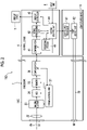
- Fig. 2 is a schematic view showing an internal configuration of the endoscope apparatus 100 shown in Fig. 1 .
- the light source device 5 comprises a light source processor 51 and a light source unit 52.
- the light source unit 52 emits illumination light to be emitted to the subject.
- the illumination light emitted from the light source unit 52 enters a light guide 53 built in the universal cord 13, and is emitted to the subject through an illumination lens 50 provided at the distal end part 10C of the insertion part 10.
- a white light source that emits white light a plurality of light sources including the white light source and a light source (for example, blue light source that emits blue light) that emits other color light, or the like is used as the light source unit 52.
- a plurality of illumination lenses 50 may be provided in accordance with the type of light emitted from the light source unit 52 on a distal end surface of the distal end part 10C.
- the light source unit 52 may be capable of switching the illumination light having different emission spectra and performing irradiation.
- a specific configuration of the light source unit 52 capable of switching the illumination light having different emission spectra and performing the irradiation will be described with reference to Figs. 10 and 11 .
- the light source processor 51 is connected to a system control unit 44 of the control device 4.
- the light source processor 51 controls the light source unit 52 based on the command from the system control unit 44.
- an imaging optical system including an objective lens 21 and a lens group 22, an imaging element 23 that images the subject through the imaging optical system, an analog/digital conversion circuit (ADC) 24, a memory 25, such as a random access memory (RAM), a communication interface (I/F) 26, an imaging control unit 27, and the light guide 53 for guiding the illumination light emitted from the light source unit 52 to the illumination lens 50 are provided.
- ADC analog/digital conversion circuit
- RAM random access memory
- I/F communication interface
- imaging control unit 27 for guiding the illumination light emitted from the light source unit 52 to the illumination lens 50 are provided.
- the light guide 53 extends from the distal end part 10C to the connector portion 13A of the universal cord 13.
- the illumination light emitted from the light source unit 52 of the light source device 5 can enter the light guide 53 in a state in which the connector portion 13A of the universal cord 13 is connected to the light source device 5.
- a charge coupled device (CCD) image sensor or a complementary metal oxide semiconductor (CMOS) image sensor is used as the imaging element 23.
- CCD charge coupled device
- CMOS complementary metal oxide semiconductor
- the imaging element 23 has a light-receiving surface on which a plurality of pixels are two-dimensionally arranged, converts an optical image formed on the light-receiving surface by the imaging optical system described above into an electrical signal (imaging signal) in each pixel, and outputs the converted electrical signal to the ADC 24.
- an imaging element on which a color filter, such as an elementary color or a complementary color, is mounted is used as the imaging element 23.
- a set of the imaging signals output from the pixels of the light-receiving surface of the imaging element 23 is referred to as a captured image signal.
- an imaging element on which no color filter is mounted may be used as the imaging element 23.
- the imaging element 23 may be disposed at the distal end part 10C in a state in which the light-receiving surface is perpendicular to an optical axis Ax of the objective lens 21, or may be disposed at the distal end part 10C in a state in which the light-receiving surface is parallel to the optical axis Ax of the objective lens 21.
- the imaging optical system provided in the endoscope 1 is composed of optical members (including the lens group 22 described above), such as a lens and a prism, which are present on an optical path of the light from the subject between the imaging element 23 and the objective lens 21, and the objective lens 21.
- optical members including the lens group 22 described above
- the imaging optical system is composed of only the objective lens 21.
- the ADC 24 converts the imaging signal output from the imaging element 23 into a digital signal having a predetermined number of bits.
- the memory 25 transitorily records the imaging signal digitally converted by the ADC 24.
- the communication I/F 26 is connected to a communication interface (I/F) 41 of the control device 4.
- the communication I/F 26 transmits the imaging signal recorded in the memory 25 to the control device 4 through a signal line in the universal cord 13.
- the imaging control unit 27 is connected to the system control unit 44 of the control device 4 via the communication I/F 26.
- the imaging control unit 27 controls the imaging element 23, the ADC 24, and the memory 25 based on the command from the system control unit 44 received by the communication I/F 26.
- the control device 4 comprises the communication I/F 41, which is connected to the communication I/F 26 of the endoscope 1 by the universal cord 13, a signal processing unit 42, a display controller 43, the system control unit 44, and a recording medium 45.
- the communication I/F 41 receives the imaging signal transmitted from the communication I/F 26 of the endoscope 1 to transmit the imaging signal to the signal processing unit 42.
- the signal processing unit 42 has a memory that transitorily records the imaging signal received from the communication I/F 41 built therein, and performs processing (image processing, such as demosaicing processing or gamma-correction processing) on the captured image signal that is a set of the imaging signals recorded in the memory to generate captured image data in such a format that recognition processing to be described below can be performed.
- the captured image data generated by the signal processing unit 42 is recorded on the recording medium 45, such as a hard disk or a flash memory.
- the display controller 43 displays a captured image based on the captured image data generated by the signal processing unit 42 on the display device 7.
- a coordinate of each pixel data constituting the captured image data generated by the signal processing unit 42 is managed in association with a coordinate of any of the display pixels constituting the display surface of the display device 7.
- the system control unit 44 controls each unit of the control device 4, and transmits the command to the imaging control unit 27 of the endoscope 1 and the light source processor 51 of the light source device 5, and integrally controls the entire endoscope apparatus 100.
- the system control unit 44 performs the control of the imaging element 23 via the imaging control unit 27.
- the system control unit 44 performs the control of the light source unit 52 via the light source processor 51.
- the system control unit 44 includes various processors that execute a program to perform processing, a RAM, and a read only memory (ROM).
- processors examples include a central processing unit (CPU), which is a general-purpose processor that executes the program to perform various pieces of processing, a programmable logic device (PLD), which is a processor of which the circuit configuration can be changed after the manufacture, such as a field programmable gate array (FPGA), and a dedicated electric circuit, which is a processor having the circuit configuration specially designed for executing specific processing, such as an application specific integrated circuit (ASIC).
- CPU central processing unit
- PLD programmable logic device
- FPGA field programmable gate array
- ASIC application specific integrated circuit
- the structure of these various processors is an electric circuit in which circuit elements, such as semiconductor elements, are combined.
- the system control unit 44 may be composed of one of the various processors, or may be composed of a combination (for example, a combination of a plurality of FPGAs or a combination of a CPU and an FPGA) of two or more processors of the same type or different types.
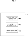
- Fig. 3 is a diagram showing an example of functional blocks of the system control unit 44 of the control device 4 shown in Fig. 2 .
- a processor of the system control unit 44 executes an examination support program stored in the ROM built in the system control unit 44 to function as a display control device comprising a captured image data acquisition unit 44A, a stage determination unit 44B, and a display control unit 44C.
- the captured image data acquisition unit 44A sequentially acquires the captured image data obtained by processing the imaging signal, which is obtained by imaging the inside of the subject by the imaging element 23, by the signal processing unit 42.
- the stage determination unit 44B determines a stage of the examination using the endoscope 1 based on various pieces of information.
- the stage determination of the examination based on various pieces of information by the stage determination unit 44B may be the determination by a specific algorithm based on various pieces of information, or may be the determination by a learning model trained through machine learning by a combination of various pieces of information and the information of a search stage.
- Examples of the stage of the examination using the endoscope 1 include an insertion stage in which the insertion part 10 of the endoscope 1 is inserted into the subject and a pulling-out stage in which the insertion part 10 of the endoscope 1 is pulled out from the subject.
- the insertion stage is an example of a first stage according to the embodiment of the present invention.
- the pulling-out stage is an example of a second stage according to the embodiment of the present invention.
- the stage of the examination using the endoscope 1 may include a stage before the insertion part 10 of the endoscope 1 is inserted into the subject or a stage after the insertion part 10 of the endoscope 1 is pulled out from the subj ect.
- the stage determination unit 44B determines the stage of the examination based on the captured image data obtained by the captured image data acquisition unit 44A. Specifically, in general, in the examination of the inside of a large intestine using the endoscope, the insertion part 10 of the endoscope 1 is inserted into a cecum, and then the insertion part 10 of the endoscope 1 is started to be pulled out. Therefore, it can be determined that the stage of the examination is the insertion stage until the cecum is detected based on the captured image data, and the stage of the examination is the pulling-out stage after the cecum is detected based on the captured image data.
- the display control unit 44C issues the command to the display controller 43 to control a screen to be displayed on the display device 7. Specifically, the display control unit 44C displays the screen including information in accordance with the determination result of the stage of the examination by the stage determination unit 44B on the display device 7.
- Fig. 4 is a diagram showing an example of the screen displayed on the display device 7 in the insertion stage of the endoscope 1 in the first embodiment.
- the display control unit 44C displays, for example, a screen 60 shown in Fig. 4 on the display device 7.
- the screen 60 includes a live image 61, a large intestine map 62, and an insertion shape image 63.
- the left side of the screen 60 is a main region, and the live image 61 is disposed in the main region.
- the right side of the screen 60 is a sub-region, and the large intestine map 62 and the insertion shape image 63 are disposed in the sub-region.
- the live image 61 is a motion picture showing an image obtained by the imaging signal continuously output from the imaging element 23 in real time.
- the large intestine map 62 and the insertion shape image 63 constitute insertion support information for supporting the insertion of the insertion part 10 of the endoscope 1 into the subject.
- the large intestine map 62 is an example of a map of the inside of the subject which is an insertion target of the endoscope 1, and is an image showing the large intestine of the subject which is the insertion target of the endoscope 1.
- the large intestine map 62 may be, for example, an image obtained by imaging the inside of the subject, or may be a general image of the large intestine prepared in advance.
- the insertion shape image 63 is an image showing the insertion shape of the insertion part 10 of the endoscope 1 inserted into the subject.
- the insertion shape image 63 is an image generated based on a detection result of a magnetic field generated from a magnetic field generation element provided in the distal end part 10C of the endoscope 1.
- the endoscope apparatus 100 further comprises a magnetic field detection device that detects the magnetic field from the magnetic field generation element of the endoscope 1 inserted into the subject from outside the subject, and the system control unit 44 generates the insertion shape image 63 based on the detection result by the magnetic field detection device.
- the insertion shape image 63 may be an image generated based on the detection result of the magnetic field by the magnetic field detection element provided in the distal end part 10C of the endoscope 1.
- the endoscope apparatus 100 further comprises a magnetic field generation element that generates the magnetic field from outside the subject to the inside of the subject, and the system control unit 44 generates the insertion shape image 63 based on the detection result of the magnetic field by the magnetic field detection element provided in the endoscope 1.
- An operator of the endoscope 1 can easily insert the insertion part 10 of the endoscope 1 into the subject by looking at the large intestine map 62 and the insertion shape image 63.
- Fig. 5 is a diagram showing an example of a screen displayed on the display device 7 in the pulling-out stage of the endoscope 1 in the first embodiment.
- the display control unit 44C displays, for example, a screen 70 shown in Fig. 5 on the display device 7.
- the screen 70 includes the live image 61, thumbnail information 71, and a large intestine imaging map 72.
- the live image 61 is disposed in the main region as in the example of Fig. 4 .
- the thumbnail information 71 and the large intestine imaging map 72 are disposed in the sub-region (region on the left side) in place of the large intestine map 62 and the insertion shape image 63 shown in Fig. 4 .
- the thumbnail information 71 and the large intestine imaging map 72 constitute observation support information for supporting the observation of the captured image obtained by the endoscope 1.
- the observation support information may be, for example, information for supporting a diagnosis based on the captured image obtained by the endoscope 1.
- the thumbnail information 71 is information indicating a plurality of still pictures, which are obtained during the insertion of the endoscope 1 into the subject or during pulling-out of the endoscope 1 from the subject, in a reduced manner.
- the thumbnail information 71 includes four still pictures, and the consecutive numbers "01", "02", “03", and "04" are attached to the still pictures.
- the thumbnail information 71 may include other text information (portion of " ⁇ " in Fig. 5 ) relating to each still picture, as in the example shown in Fig. 5 .
- Examples of the text information include a position or a time at which the corresponding still picture is obtained, the findings input by the operator in a case in which the corresponding still picture is obtained, and a result of the image analysis in a case in which the corresponding still picture is obtained.
- the large intestine imaging map 72 indicates a portion in which the still pictures described above are obtained in the large intestine map 62 shown in Fig. 4 by the consecutive numbers described above.
- the operator of the endoscope 1 can easily observe the captured image obtained by the endoscope 1 or make a diagnosis based on the captured image obtained by the endoscope 1.
- the system control unit 44 may display the screen including the live image 61 and the insertion support information on the display device 7 in the insertion stage, and may display the screen including the live image 61 and the observation support information on the display device 7 in the pulling-out stage.
- the system control unit 44 may display the screen including the live image 61 and the insertion support information on the display device 7 in the insertion stage, and may display the screen including the live image 61 and the observation support information on the display device 7 in the pulling-out stage.
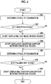
- Fig. 6 is a flowchart showing an example of display control processing by the control device 4 in the first embodiment.
- the control device 4 executes, for example, the processing shown in Fig. 6 .
- control device 4 determines the stage of the examination using the endoscope 1 (step S61). Then, the control device 4 determines, based on the result of step S61, whether or not the stage of the examination using the endoscope 1 is the insertion stage in which the endoscope 1 is inserted into the subject (step S62). In a case in which it is not the insertion stage (step S62: No), the control device 4 returns to step S61.
- step S62 in a case in which it is the insertion stage (step S62: Yes), the control device 4 starts displaying the live image 61 in the main region (region on the left side) of the display device 7 (step S63). In addition, the control device 4 starts displaying the insertion support information (large intestine map 62 and insertion shape image 63) in the sub-region (region on the right side) (step S64).
- step S65 determines the stage of the examination using the endoscope 1 (step S65). Then, the control device 4 determines, based on the result of step S65, whether or not the stage of the examination using the endoscope 1 is the pulling-out stage in which the endoscope 1 is pulled out from the subject (step S66). In a case in which it is not the pulling-out stage (step S66: No), the control device 4 returns to step S65.
- step S66 in a case in which it is the pulling-out stage (step S66: Yes), the control device 4 starts displaying the observation support information (thumbnail information 71 and large intestine imaging map 72) in the sub-region (step S67), and terminates a series of processing.
- the endoscope apparatus 100 determines the stage of the examination by the endoscope 1, and then displays the screen including the insertion support information for supporting the insertion of the endoscope 1 into the subject in a case in which it is the insertion stage, and displays the screen including the observation support information for supporting the observation of the image obtained by the endoscope 1 in a case in which it is the pulling-out stage.
- the endoscope apparatus 100 determines the stage of the examination by the endoscope 1, and then displays the screen including the insertion support information for supporting the insertion of the endoscope 1 into the subject in a case in which it is the insertion stage, and displays the screen including the observation support information for supporting the observation of the image obtained by the endoscope 1 in a case in which it is the pulling-out stage.
- stage determination unit 44B determines the stage of the examination based on the captured image data, but the present invention is not limited to such a configuration.
- the stage determination unit 44B may determine the stage of the examination based on the detection result of the magnetic field generated from the magnetic field generation element provided in the distal end part 10C of the endoscope 1.
- the endoscope apparatus 100 further comprises the magnetic field detection device that detects the magnetic field from the magnetic field generation element of the endoscope 1 inserted into the subject from outside the subject, and the stage determination unit 44B determines the stage of the examination based on the detection result by the magnetic field detection device.
- the stage determination unit 44B may determine the stage of the examination based on the detection result of the magnetic field by the magnetic field detection element provided in the distal end part 10C of the endoscope 1.
- the endoscope apparatus 100 further comprises the magnetic field generation element that generates the magnetic field from outside the subject to the inside of the subject, and the stage determination unit 44B determines the stage of the examination based on the detection result of the magnetic field by the magnetic field detection element provided in the endoscope 1.
- the stage determination unit 44B may determine the stage of the examination based on acceleration information obtained by an accelerometer provided in the distal end part 10C of the endoscope 1. For example, in the insertion stage, the endoscope 1 moves toward the distal end of the endoscope 1, and in the pulling-out stage, the endoscope 1 moves in a direction opposite to a direction of the distal end of the endoscope 1. Therefore, by specifying a moving direction of the endoscope 1 based on the acceleration information described above, it is possible to determine whether the stage of the examination is the insertion stage or the pulling-out stage.
- the stage determination unit 44B may determine the stage of the examination based on switching of the illumination light emitted by the endoscope 1. For example, in the light source device 5 shown in Fig. 2 , the white light and special light for image enhancement can be switched.
- This switching may be performed by a light source switching operation by the operator of the endoscope 1, or may be automatically performed based on the captured image data or the like obtained by the captured image data acquisition unit 44A described above.
- the white light is used in the insertion stage and the special light is used in the pulling-out stage, so that it is possible to determine the stage of the examination based on the switching of the illumination light emitted by the endoscope 1.
- the configuration has been described in which the system control unit 44 displays the map (large intestine map 62) of the inside of the subject and the image (insertion shape image 63) of the insertion shape of the endoscope 1 as the information for supporting the insertion of the endoscope 1 into the subject, but the present invention is not limited to such a configuration.
- the system control unit 44 may display any of the map (large intestine map 62) of the inside of the subject and the image (insertion shape image 63) of the insertion shape of the endoscope 1 as the information for supporting the insertion of the endoscope 1 into the subject, on the display device 7.
- the system control unit 44 may display an elapsed time from the start of the insertion of the endoscope 1 into the subject as the information for supporting the insertion of the endoscope 1 into the subject, on the display device 7.
- the operator of the endoscope 1 can perform the insertion operation while easily grasping the load on the subject accompanied by the insertion of the endoscope 1.
- the configuration has been described in which the system control unit 44 displays the still picture (thumbnail information 71) obtained by the imaging element 23 provided in the endoscope 1 and the information (large intestine imaging map 72) indicating the position inside the subject at which the still picture is obtained as the information for supporting the observation, but the present invention is not limited to such a configuration.
- thumbnail information 71 does not have to include the text information or the consecutive numbers described above.
- system control unit 44 displays various pieces of information detected based on the image obtained by the imaging element 23 provided in the endoscope 1 on the display device 7 as the information for supporting the observation.
- the information detected based on the image obtained by the imaging element 23 is, for example, information on a region-of-interest.
- the information on the region-of-interest is, for example, an image of a lesion, such as a tumor, an outline of the lesion, or the like.
- the information on the region-of-interest may be information, such as the number or size of detected lesions.
- the information detected based on the image obtained by the imaging element 23 may be a similar case image selected based on the image obtained by the imaging element 23.
- the captured images of various past cases are registered in an internal or external database of the endoscope apparatus 100.
- the system control unit 44 searches the database described above for an image similar to the image obtained by the imaging element 23, and displays the image obtained by the search on the display device 7 as the similar case image.
- a configuration may be adopted in which the system control unit 44 displays information indicating the tumor that is likely to occur in the site inside the subject into which the endoscope 1 is being inserted on the display device 7 as the information for supporting the observation.
- the name of the tumor that is likely to occur or the like is registered in the internal or external database of the endoscope apparatus 100.
- the system control unit 44 specifies the site inside the large intestine into which the endoscope 1 is being inserted, searches the database described above for the name of the tumor that is likely to occur or the like for the specified site, and displays the name of the tumor or the like obtained by the search on the display device 7.
- the site inside the large intestine into which the endoscope 1 is being inserted can be specified by using, for example, the image obtained by the imaging element 23 or a combination of the magnetic field generation element and the magnetic field detection device described above.
- a configuration may be adopted in which the system control unit 44 displays information indicating a recommended observation method of the site inside the subject into which the endoscope 1 is being inserted on the display device 7 as the information for supporting the observation.
- the recommended observation method of the live image is registered in the internal or external database of the endoscope apparatus 100.
- the system control unit 44 specifies the site inside the large intestine into which the endoscope 1 is being inserted, searches the database described above for the recommended observation method of the specified site, and displays the observation method obtained by the search on the display device 7.
- the site inside the large intestine into which the endoscope 1 is being inserted can be specified by using, for example, the image obtained by the imaging element 23 or a combination of the magnetic field generation element and the magnetic field detection device described above.
- the system control unit 44 displays information indicating a past examination result of the inside of the subject on the display device 7 as the information for supporting the observation.
- the system control unit 44 acquires the information indicating the result of the examination performed in the past on the subject into which the endoscope 1 is being inserted from the internal or external database of the endoscope apparatus 100, and displays the acquired information indicating the result of the examination on the display device 7.
- the information indicating the result of the examination include the image obtained by imaging in the examination, a result of analysis based on the image, or the like.
- system control unit 44 may display information indicating an elapsed time from the start of pulling-out of the endoscope 1 from the subject on the display device 7 as the information for supporting the observation.
- the operator of the endoscope 1 can perform the pulling-out operation while easily grasping the load on the subject accompanied by the pulling-out of the endoscope 1.
- the system control unit 44 may display a screen including an image obtained by the imaging element 23 in a state in which the inside of the subject is irradiated with the white light on the display device 7 as the information for supporting the insertion in the insertion stage, and may display a screen including an image obtained by the imaging element 23 in a state in which the inside of the subject is irradiated with the special light having a different emission spectrum from the white light on the display device 7 as the information for supporting the observation in the pulling-out stage.
- the image obtained by the imaging element 23 in a state in which the inside of the subject is irradiated with the special light is an image suitable for the observation or diagnosis described above.
- the system control unit 44 controls the light source device 5 to emit the white light, and displays the screen including the live image 61 based on the imaging signal obtained by the imaging element 23 on the display device 7.
- the system control unit 44 controls the light source device 5 to emit the special light, and displays the screen including the live image 61 based on the imaging signal obtained by the imaging element 23 on the display device 7.
- the configuration has been described in which the insertion stage and the pulling-out stage are determined and the useful information is displayed in each of these stages.
- the second embodiment a configuration will be described in which it is determined whether the stage is the stage in which the insertion part 10 of the endoscope 1 is inserted into any site inside the subject, and the useful information is displayed in each of these stages.
- examples of the stage of the examination determined by the stage determination unit 44B include an esophagus insertion stage in which the insertion part 10 of the endoscope 1 is inserted into the esophagus, and a stomach insertion stage in which the insertion part 10 of the endoscope 1 is inserted into the stomach.
- the esophagus is an example of a first site inside the subject.
- the stomach is an example of a second site inside the subject.
- the stage determination unit 44B determines the esophagus insertion stage and the stomach insertion stage based on the captured image data obtained by the captured image data acquisition unit 44A.
- Fig. 7 is a diagram showing an example of a screen displayed on the display device 7 in the esophagus insertion stage of the endoscope 1 in the second embodiment.
- the display control unit 44C displays, for example, a screen 80 shown in Fig. 7 on the display device 7.
- the screen 80 includes the live image 61, an esophagus map 101, and the insertion shape image 63.
- the live image 61 is disposed in the main region (region on the left side).
- the esophagus map 101 and the insertion shape image 63 are disposed in the sub-region (region on the right side).
- the live image 61 is a motion picture showing an image obtained by the imaging signal continuously output from the imaging element 23 in real time.
- the esophagus map 101 and the insertion shape image 63 constitute esophagus insertion support information for supporting the insertion of the insertion part 10 of the endoscope 1 into the esophagus.
- the esophagus map 101 is an image indicating the esophagus of the subject which is the insertion target of the endoscope 1.
- the esophagus map 101 may be, for example, an image obtained by imaging the inside of the subject, or may be a general image of the large intestine prepared in advance.
- the insertion shape image 63 indicates the shape of the insertion part 10 of the endoscope 1 inserted into the esophagus inside the subject.
- the operator of the endoscope 1 can easily insert the insertion part 10 of the endoscope 1 into the esophagus.
- Fig. 8 is a diagram showing an example of a screen displayed on the display device 7 in the stomach insertion stage of the endoscope 1 in the second embodiment.
- the display control unit 44C displays, for example, a screen 90 shown in Fig. 8 on the display device 7.
- the screen 90 includes the live image 61, a stomach map 102, and the insertion shape image 63.
- the live image 61 is disposed in the main region as in the example of Fig. 7 .
- the stomach map 102 and the insertion shape image 63 are disposed in the sub-region in place of the esophagus map 101 and the insertion shape image 63 shown in Fig. 7 .
- the stomach map 102 and the insertion shape image 63 constitute stomach insertion support information for supporting the insertion of the insertion part 10 of the endoscope 1 into the stomach inside the subject.
- the stomach map 102 is an image indicating the stomach of the subject which is the insertion target of the endoscope 1.
- the stomach map 102 may be, for example, an image obtained by imaging the inside of the subject, or may be a general image of the large intestine prepared in advance.
- the insertion shape image 63 indicates the shape of the insertion part 10 of the endoscope 1 inserted into the stomach inside the subj ect.
- the operator of the endoscope 1 can easily insert the insertion part 10 of the endoscope 1 into the stomach.
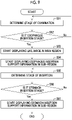
- Fig. 9 is a flowchart showing an example of the display control processing of the control device 4 in the second embodiment.
- the control device 4 executes, for example, the processing shown in Fig. 9 .
- the control device 4 determines the stage of the examination using the endoscope 1 (step S91). Then, the control device 4 determines, based on the result of step S91, whether or not the stage of the examination using the endoscope 1 is the esophagus insertion stage in which the endoscope 1 is inserted into the esophagus of the subject (step S92). In a case in which it is not the esophagus insertion stage (step S92: No), the control device 4 returns to step S91.
- step S92 in a case in which it is the esophagus insertion stage (step S92: Yes), the control device 4 starts displaying the live image 61 in the main region (region on the left side) of the display device 7 (step S93). In addition, the control device 4 starts displaying the esophagus insertion support information (esophagus map 101 and insertion shape image 63) in the sub-region (region on the right side) (step S94).
- the esophagus insertion support information esophagus map 101 and insertion shape image 63
- step S95 determines the stage of the examination using the endoscope 1 (step S95). Then, the control device 4 determines, based on the result of step S95, whether or not the stage of the examination using the endoscope 1 is the stomach insertion stage in which the endoscope 1 is inserted into the stomach of the subject (step S96). In a case in which it is not the stomach insertion stage (step S96: No), the control device 4 returns to step S95.
- step S96 in a case in which it is the stomach insertion stage (step S96: Yes), the control device 4 starts displaying the stomach insertion support information (stomach map 102 and insertion shape image 63) in the sub-region (step S97), and terminates a series of processing.
- the endoscope apparatus 100 of the second embodiment determines the stage of the examination by the endoscope 1, and then displays the screen including the esophagus insertion support information for supporting the insertion of the endoscope 1 into the esophagus in a case in which it is the esophagus insertion stage, and displays the screen including the stomach insertion support information for supporting the insertion of the endoscope 1 into the stomach in a case in which it is the stomach insertion stage.
- the endoscope apparatus 100 of the second embodiment determines the stage of the examination by the endoscope 1, and then displays the screen including the esophagus insertion support information for supporting the insertion of the endoscope 1 into the esophagus in a case in which it is the esophagus insertion stage, and displays the screen including the stomach insertion support information for supporting the insertion of the endoscope 1 into the stomach in a case in which it is the stomach insertion stage.
- the first site and the second site are not limited to these.
- the first site and the second site may be two sites among a sigmoid colon, a descending colon, a transverse colon, and an ascending colon.
- the number of sites in which the insertion is determined may be three or more, and the system control unit 44 may display information for supporting the insertion of the insertion part 10 into the target site for each site in which the insertion is determined on the display device 7.
- stage determination unit 44B determines the stage of the examination (insertion site) based on the captured image data, but the present invention is not limited to such a configuration.
- the stage determination unit 44B may determine the stage of the examination based on the detection result of the magnetic field generated from the magnetic field generation element provided in the distal end part 10C of the endoscope 1.
- the endoscope apparatus 100 further comprises the magnetic field detection device that detects the magnetic field from the magnetic field generation element of the endoscope 1 inserted into the subject from outside the subject, and the stage determination unit 44B determines the stage of the examination based on the detection result by the magnetic field detection device.
- the stage determination unit 44B may determine the stage of the examination based on the detection result of the magnetic field by the magnetic field detection element provided in the distal end part 10C of the endoscope 1.
- the endoscope apparatus 100 further comprises the magnetic field generation element that generates the magnetic field from outside the subject to the inside of the subject, and the stage determination unit 44B determines the stage of the examination based on the detection result of the magnetic field by the magnetic field detection element provided in the endoscope 1.
- the first and second embodiments may be combined. That is, the system control unit 44 may determine, for example, the insertion stage and the pulling-out stage for each of a plurality of sites inside the subject, and may display the insertion support information or the observation support information for each site during the insertion on the display device 7 in accordance with the determined stage.
- Fig. 10 is a diagram showing an example of the light source device 5 capable of switching the illumination light having different emission spectra and performing the irradiation.
- Fig. 11 is a diagram showing an example of a spectrum of the light generated by the light source device 5 shown in Fig. 10 .
- the light source device 5 shown in Fig. 2 comprises the light source processor 51, the light source unit 52, and an optical path coupling unit 54.
- the light source unit 52 has, for example, a plurality of semiconductor light sources, each of which is turned on or off, and in a case in which the light source unit 52 is turned on, the emission amount of each semiconductor light source is controlled to emit the illumination light for illuminating an observation target.
- the light source unit 52 has LEDs of four colors, a violet light emitting diode (V-LED) 52a, a blue light emitting diode (B-LED) 52b, a green light emitting diode (G-LED) 52c, and a red light emitting diode (R-LED) 52d.
- the V-LED 52a generates violet light V of which a central wavelength is in a range of 405 ⁇ 10 nm and a wavelength range is in a range of 380 to 420 nm.
- the B-LED 52b generates blue light B of which a central wavelength is in a range of 450 ⁇ 10 nm and a wavelength range is in a range of 420 to 500 nm.
- the G-LED 52c generates green light G of which a wavelength range is in a range of 480 to 600 nm.
- the R-LED 52d generates red light R of which a central wavelength is in a range of 620 to 630 nm and a wavelength range is in a range of 600 to 650 nm.
- the light source processor 51 controls the V-LED 52a, the B-LED 52b, the G-LED 52c, and the R-LED 52d. By independently controlling each of the LEDs 52a to 52d, the light source processor 51 can emit the violet light V, the blue light B, the green light G, or the red light R by independently changing a light amount. In addition, in a normal observation mode, the light source processor 51 controls each of the LEDs 52a to 52d to emit the white light in which a light amount ratio of the violet light V, the blue light B, the green light G, and the red light R is Vc:Bc:Gc:Rc. It should be noted that Vc, Bc, Gc, Rc > 0.
- the light source processor 51 controls each of the LEDs 52a to 52d to emit the special light in which the light amount ratio of the violet light V, the blue light B, the green light G, and the red light R as short-wavelength narrow band light is Vs:Bs:Gs:Rs.
- the light amount ratio Vs:Bs:Gs:Rs is different from the light amount ratio Vc:Bc:Gc:Rc used in the normal observation mode, and is appropriately determined in accordance with the observation purpose.
- Vs in a case in which superficial blood vessels are enhanced, it is preferable to make Vs larger than Bs, Gs, and Rs, and in a case in which mesopelagic blood vessels are enhanced, it is preferable to make Gs larger than Vs, Gs, and Rs.
- a control program which is stored in the ROM of the control device 4, is stored in a program computer-readable non-transitory storage medium.
- Examples of such a "computer-readable storage medium” include an optical medium, such as a compact disc-ROM (CD-ROM), and a magnetic storage medium, such as a universal serial bus (USB) memory, or a memory card.
- a program can also be provided by being downloaded via a network.
- the endoscope apparatus 100 has been described as an example of the endoscope system according to the embodiment of the present invention, the endoscope system according to the embodiment of the present invention may be realized by a plurality of devices connected to each other via the network. For example, a configuration may be adopted in which at least a part of the processing by the control device 4 described above is executed by another device connected to the endoscope apparatus 100 via the network.
- the display unit according to the embodiment of the present invention may be realized by a plurality of display devices.
- the main region described above may be composed of one display device of the plurality of display devices, and the sub-region described above may be composed of the remaining display devices of the plurality of display devices.
- the present invention it is possible to provide the endoscope system, the control program, and the display method that can provide useful information in accordance with the stage of the examination to the operator of the endoscope.
Landscapes
- Health & Medical Sciences (AREA)
- Life Sciences & Earth Sciences (AREA)
- Surgery (AREA)
- Engineering & Computer Science (AREA)
- Physics & Mathematics (AREA)
- Optics & Photonics (AREA)
- Biomedical Technology (AREA)
- Molecular Biology (AREA)
- Pathology (AREA)
- Nuclear Medicine, Radiotherapy & Molecular Imaging (AREA)
- Biophysics (AREA)
- Heart & Thoracic Surgery (AREA)
- Medical Informatics (AREA)
- Radiology & Medical Imaging (AREA)
- Animal Behavior & Ethology (AREA)
- General Health & Medical Sciences (AREA)
- Public Health (AREA)
- Veterinary Medicine (AREA)
- Signal Processing (AREA)
- Microelectronics & Electronic Packaging (AREA)
- Endoscopes (AREA)
Abstract
Description
- The present invention relates to an endoscope system, a control program, and a display method.
- In the related art, an endoscope system comprising an imaging element at a distal end part of an endoscope and capable of displaying a live image obtained by the imaging element is known. In addition,
JP2005-77832A -
JP2014-83289A JP2009-226170A - Generally, in an examination of an inside of a large intestine using an endoscope, after inserting an insertion part of the endoscope into a subject, the inside of the subject is observed while pulling out the insertion part of the endoscope from the subject. In such an examination, useful information for an operator, such as a doctor, of the endoscope varies between a stage of inserting the insertion part of the endoscope into the subject and a stage of performing the observation while pulling out the insertion part of the endoscope from the subj ect.
- For example, in the stage of inserting the insertion part of the endoscope into the subject, it is necessary not to apply an excessive load to the subject, so that the difficulty of operating the endoscope is high, and information for supporting smooth insertion of the insertion part of the endoscope into the subject is useful.
- On the other hand, in the stage of performing the observation while pulling out the insertion part of the endoscope from the subject, the difficulty of operating the endoscope is not as high as in a case of insertion, but information for supporting the observation is useful such that a singular portion is not overlooked in the observation based on the live image or the like.
- However, the related art described above cannot provide useful information in accordance with a stage of the examination to the operator of the endoscope.
- The present invention has been made in view of the circumstances described above, and is to provide an endoscope system, a control program, and a display method that can provide useful information in accordance with a stage of the examination to an operator of an endoscope.
- An aspect of the present invention relates to an endoscope system comprising a determination unit that determines a stage of an examination by an endoscope, and a display unit that switches a display image in accordance with a determination result by the determination unit, in which the stage of the examination includes a first stage in which the endoscope is inserted into a subject, and a second stage in which the endoscope is pulled out from the subject, and the display unit displays a screen including information for supporting insertion of the endoscope into the subject in a case in which it is determined that the stage of the examination is the first stage, and displays a screen including information for supporting observation of an image obtained by the endoscope in a case in which it is determined that the stage of the examination is the second stage.
- Another aspect of the present invention relates to a control program causing a computer to function as the determination unit and the display unit of the endoscope system described above.
- Still another aspect of the present invention relates to a display method comprising determining a stage of an examination by an endoscope, and switching a display image in accordance with a determination result of the stage of the examination, in which the stage of the examination includes a first stage in which the endoscope is inserted into a subject, and a second stage in which the endoscope is pulled out from the subject, and in a case in which it is determined that the stage of the examination is the first stage, a screen including information for supporting insertion of the endoscope into the subject is displayed, and in a case in which it is determined that the stage of the examination is the second stage, a screen including information for supporting observation of an image obtained by the endoscope is displayed.
- Still another aspect of the present invention relates to an endoscope system comprising a determination unit that determines a stage of an examination by an endoscope, and a display unit that switches a display image in accordance with a determination result by the determination unit, in which the stage of the examination includes a first stage in which the endoscope is inserted into a first site inside a subject, and a second stage in which the endoscope is inserted into a second site inside the subject different from the first site, and the display unit displays a screen including at least any of information for supporting insertion of the endoscope into a site into which the endoscope is being inserted among sites inside the subject, or information for supporting observation of the site during the insertion, based on the determination result by the determination unit.
- Still another aspect of the present invention relates to a control program causing a computer to function as the determination unit and the display unit of the endoscope system described above.
- Still another aspect of the present invention relates to a control method comprising determining a stage of an examination by an endoscope, and switching a display image in accordance with a determination result of the stage of the examination, in which the stage of the examination includes a first stage in which the endoscope is inserted into a first site inside a subject, and a second stage in which the endoscope is inserted into a second site inside the subject different from the first site, and a screen including at least any of information for supporting insertion of the endoscope into a site into which the endoscope is being inserted among sites inside the subject, or information for supporting observation of the site during the insertion, is displayed based on the determination result of the stage of the examination.
- According to the present invention, it is possible to provide the endoscope system, the control program, and the display method that can provide useful information in accordance with the stage of the examination to the operator of the endoscope.
-
-
Fig. 1 is a view showing an example of anendoscope apparatus 100 which is one embodiment of the present invention. -
Fig. 2 is a schematic view showing an internal configuration of theendoscope apparatus 100 shown inFig. 1 . -
Fig. 3 is a diagram showing an example of functional blocks of asystem control unit 44 of a control device 4 shown inFig. 2 . -
Fig. 4 is a diagram showing an example of a screen displayed on thedisplay device 7 in an insertion stage of an endoscope 1 in a first embodiment. -
Fig. 5 is a diagram showing an example of a screen displayed on thedisplay device 7 in a pulling-out stage of the endoscope 1 in the first embodiment. -
Fig. 6 is a flowchart showing an example of display control processing by the control device 4 in the first embodiment. -
Fig. 7 is a diagram showing an example of a screen displayed on thedisplay device 7 in an esophagus insertion stage of the endoscope 1 in a second embodiment. -
Fig. 8 is a diagram showing an example of a screen displayed on thedisplay device 7 in a stomach insertion stage of the endoscope 1 in the second embodiment. -
Fig. 9 is a flowchart showing an example of the display control processing of the control device 4 in the second embodiment. -
Fig. 10 is a diagram showing an example of alight source device 5 capable of switching illumination light having different emission spectra and performing irradiation. -
Fig. 11 is a diagram showing an example of a spectrum of light generated by thelight source device 5 shown inFig. 10 . - In the following, embodiments of the present invention will be described with reference to the drawings.
-
Fig. 1 is a view showing an example of anendoscope apparatus 100 which is one embodiment of the present invention. - The
endoscope apparatus 100 is an example of an endoscope system according to the embodiment of the present invention. As shown inFig. 1 , theendoscope apparatus 100 comprises an endoscope 1, and a control device 4 and alight source device 5 to which the endoscope 1 is connected. - A
display device 7 that displays a captured image or the like obtained by imaging an inside of a subject by the endoscope 1 and aninput unit 6, which is an interface for inputting various pieces of information to the control device 4 are connected to the control device 4. The control device 4 controls the endoscope 1, thelight source device 5, and thedisplay device 7. - The
display device 7 has a display surface on which display pixels are two-dimensionally arranged, and pixel data constituting image data is drawn on each display pixel on the display surface, thereby performing the display of an image based on the image data. Thedisplay device 7 constitutes a display unit that switches the display image in accordance with the command from the control device 4. - The endoscope 1 includes an
insertion part 10 which is a tubular member extending in one direction and is inserted into the subject, an operating part 11 which is provided in a base end part of theinsertion part 10 and includes an operation member for performing an observation mode switching operation, an imaging recording operation, a forcep operation, an air supply/water supply operation, and a suction operation, anangle knob 12 provided adjacent to the operating part 11, and auniversal cord 13 includingconnector portions light source device 5 and the control device 4, respectively. - It should be noted that, although not shown in
Fig. 1 , various channels, such as a forcep hole for inserting forceps for sampling a living body tissue, such as cells or polyps, an air supply/water supply channel, and a suction channel, are provided inside the operating part 11 and theinsertion part 10. - The
insertion part 10 is composed of aflexible part 10A having flexibility, abendable part 10B provided at a distal end of theflexible part 10A, and a harddistal end part 10C provided at a distal end of thebendable part 10B. - The
bendable part 10B is configured to be bendable by a rotational movement operation of theangle knob 12. Depending on the site of the subject in which the endoscope 1 is used, thebendable part 10B can be bent in any direction and at any angle, and thedistal end part 10C can be directed in a desired direction. -
Fig. 2 is a schematic view showing an internal configuration of theendoscope apparatus 100 shown inFig. 1 . - The
light source device 5 comprises alight source processor 51 and alight source unit 52. Thelight source unit 52 emits illumination light to be emitted to the subject. The illumination light emitted from thelight source unit 52 enters alight guide 53 built in theuniversal cord 13, and is emitted to the subject through anillumination lens 50 provided at thedistal end part 10C of theinsertion part 10. - A white light source that emits white light, a plurality of light sources including the white light source and a light source (for example, blue light source that emits blue light) that emits other color light, or the like is used as the
light source unit 52. A plurality ofillumination lenses 50 may be provided in accordance with the type of light emitted from thelight source unit 52 on a distal end surface of thedistal end part 10C. - In addition, the
light source unit 52 may be capable of switching the illumination light having different emission spectra and performing irradiation. A specific configuration of thelight source unit 52 capable of switching the illumination light having different emission spectra and performing the irradiation will be described with reference toFigs. 10 and 11 . - The
light source processor 51 is connected to asystem control unit 44 of the control device 4. Thelight source processor 51 controls thelight source unit 52 based on the command from thesystem control unit 44. - In the
distal end part 10C of the endoscope 1, an imaging optical system including anobjective lens 21 and alens group 22, animaging element 23 that images the subject through the imaging optical system, an analog/digital conversion circuit (ADC) 24, amemory 25, such as a random access memory (RAM), a communication interface (I/F) 26, animaging control unit 27, and thelight guide 53 for guiding the illumination light emitted from thelight source unit 52 to theillumination lens 50 are provided. - The
light guide 53 extends from thedistal end part 10C to theconnector portion 13A of theuniversal cord 13. The illumination light emitted from thelight source unit 52 of thelight source device 5 can enter thelight guide 53 in a state in which theconnector portion 13A of theuniversal cord 13 is connected to thelight source device 5. - A charge coupled device (CCD) image sensor or a complementary metal oxide semiconductor (CMOS) image sensor is used as the
imaging element 23. - The
imaging element 23 has a light-receiving surface on which a plurality of pixels are two-dimensionally arranged, converts an optical image formed on the light-receiving surface by the imaging optical system described above into an electrical signal (imaging signal) in each pixel, and outputs the converted electrical signal to theADC 24. For example, an imaging element on which a color filter, such as an elementary color or a complementary color, is mounted, is used as theimaging element 23. A set of the imaging signals output from the pixels of the light-receiving surface of theimaging element 23 is referred to as a captured image signal. - It should be noted that, in a case in which a light source unit in which the spectrum of the white light emitted from the white light source is divided in a time-division manner by a plurality of color filters to generate the illumination light is used as the
light source unit 52, an imaging element on which no color filter is mounted may be used as theimaging element 23. - The
imaging element 23 may be disposed at thedistal end part 10C in a state in which the light-receiving surface is perpendicular to an optical axis Ax of theobjective lens 21, or may be disposed at thedistal end part 10C in a state in which the light-receiving surface is parallel to the optical axis Ax of theobjective lens 21. - The imaging optical system provided in the endoscope 1 is composed of optical members (including the
lens group 22 described above), such as a lens and a prism, which are present on an optical path of the light from the subject between theimaging element 23 and theobjective lens 21, and theobjective lens 21. There is also a case in which the imaging optical system is composed of only theobjective lens 21. - The
ADC 24 converts the imaging signal output from theimaging element 23 into a digital signal having a predetermined number of bits. - The
memory 25 transitorily records the imaging signal digitally converted by theADC 24. - The communication I/
F 26 is connected to a communication interface (I/F) 41 of the control device 4. The communication I/F 26 transmits the imaging signal recorded in thememory 25 to the control device 4 through a signal line in theuniversal cord 13. - The
imaging control unit 27 is connected to thesystem control unit 44 of the control device 4 via the communication I/F 26. Theimaging control unit 27 controls theimaging element 23, theADC 24, and thememory 25 based on the command from thesystem control unit 44 received by the communication I/F 26. - The control device 4 comprises the communication I/
F 41, which is connected to the communication I/F 26 of the endoscope 1 by theuniversal cord 13, asignal processing unit 42, adisplay controller 43, thesystem control unit 44, and arecording medium 45. - The communication I/
F 41 receives the imaging signal transmitted from the communication I/F 26 of the endoscope 1 to transmit the imaging signal to thesignal processing unit 42. - The
signal processing unit 42 has a memory that transitorily records the imaging signal received from the communication I/F 41 built therein, and performs processing (image processing, such as demosaicing processing or gamma-correction processing) on the captured image signal that is a set of the imaging signals recorded in the memory to generate captured image data in such a format that recognition processing to be described below can be performed. The captured image data generated by thesignal processing unit 42 is recorded on therecording medium 45, such as a hard disk or a flash memory. - The
display controller 43 displays a captured image based on the captured image data generated by thesignal processing unit 42 on thedisplay device 7. A coordinate of each pixel data constituting the captured image data generated by thesignal processing unit 42 is managed in association with a coordinate of any of the display pixels constituting the display surface of thedisplay device 7. - The
system control unit 44 controls each unit of the control device 4, and transmits the command to theimaging control unit 27 of the endoscope 1 and thelight source processor 51 of thelight source device 5, and integrally controls theentire endoscope apparatus 100. For example, thesystem control unit 44 performs the control of theimaging element 23 via theimaging control unit 27. In addition, thesystem control unit 44 performs the control of thelight source unit 52 via thelight source processor 51. - The
system control unit 44 includes various processors that execute a program to perform processing, a RAM, and a read only memory (ROM). - Examples of various processors include a central processing unit (CPU), which is a general-purpose processor that executes the program to perform various pieces of processing, a programmable logic device (PLD), which is a processor of which the circuit configuration can be changed after the manufacture, such as a field programmable gate array (FPGA), and a dedicated electric circuit, which is a processor having the circuit configuration specially designed for executing specific processing, such as an application specific integrated circuit (ASIC).
- More specifically, the structure of these various processors is an electric circuit in which circuit elements, such as semiconductor elements, are combined.
- The
system control unit 44 may be composed of one of the various processors, or may be composed of a combination (for example, a combination of a plurality of FPGAs or a combination of a CPU and an FPGA) of two or more processors of the same type or different types. -
Fig. 3 is a diagram showing an example of functional blocks of thesystem control unit 44 of the control device 4 shown inFig. 2 . - A processor of the
system control unit 44 executes an examination support program stored in the ROM built in thesystem control unit 44 to function as a display control device comprising a captured imagedata acquisition unit 44A, astage determination unit 44B, and adisplay control unit 44C. - The captured image
data acquisition unit 44A sequentially acquires the captured image data obtained by processing the imaging signal, which is obtained by imaging the inside of the subject by theimaging element 23, by thesignal processing unit 42. - The
stage determination unit 44B determines a stage of the examination using the endoscope 1 based on various pieces of information. The stage determination of the examination based on various pieces of information by thestage determination unit 44B may be the determination by a specific algorithm based on various pieces of information, or may be the determination by a learning model trained through machine learning by a combination of various pieces of information and the information of a search stage. - Examples of the stage of the examination using the endoscope 1 include an insertion stage in which the
insertion part 10 of the endoscope 1 is inserted into the subject and a pulling-out stage in which theinsertion part 10 of the endoscope 1 is pulled out from the subject. The insertion stage is an example of a first stage according to the embodiment of the present invention. The pulling-out stage is an example of a second stage according to the embodiment of the present invention. In addition, the stage of the examination using the endoscope 1 may include a stage before theinsertion part 10 of the endoscope 1 is inserted into the subject or a stage after theinsertion part 10 of the endoscope 1 is pulled out from the subj ect. - For example, the
stage determination unit 44B determines the stage of the examination based on the captured image data obtained by the captured imagedata acquisition unit 44A. Specifically, in general, in the examination of the inside of a large intestine using the endoscope, theinsertion part 10 of the endoscope 1 is inserted into a cecum, and then theinsertion part 10 of the endoscope 1 is started to be pulled out. Therefore, it can be determined that the stage of the examination is the insertion stage until the cecum is detected based on the captured image data, and the stage of the examination is the pulling-out stage after the cecum is detected based on the captured image data. - The
display control unit 44C issues the command to thedisplay controller 43 to control a screen to be displayed on thedisplay device 7. Specifically, thedisplay control unit 44C displays the screen including information in accordance with the determination result of the stage of the examination by thestage determination unit 44B on thedisplay device 7. -
Fig. 4 is a diagram showing an example of the screen displayed on thedisplay device 7 in the insertion stage of the endoscope 1 in the first embodiment. - In a case in which the
stage determination unit 44B determines that the stage of the examination is the insertion stage of theendoscope apparatus 100, thedisplay control unit 44C displays, for example, ascreen 60 shown inFig. 4 on thedisplay device 7. Thescreen 60 includes alive image 61, alarge intestine map 62, and aninsertion shape image 63. - The left side of the
screen 60 is a main region, and thelive image 61 is disposed in the main region. The right side of thescreen 60 is a sub-region, and thelarge intestine map 62 and theinsertion shape image 63 are disposed in the sub-region. - The
live image 61 is a motion picture showing an image obtained by the imaging signal continuously output from theimaging element 23 in real time. - The
large intestine map 62 and theinsertion shape image 63 constitute insertion support information for supporting the insertion of theinsertion part 10 of the endoscope 1 into the subject. Thelarge intestine map 62 is an example of a map of the inside of the subject which is an insertion target of the endoscope 1, and is an image showing the large intestine of the subject which is the insertion target of the endoscope 1. Thelarge intestine map 62 may be, for example, an image obtained by imaging the inside of the subject, or may be a general image of the large intestine prepared in advance. - The
insertion shape image 63 is an image showing the insertion shape of theinsertion part 10 of the endoscope 1 inserted into the subject. For example, theinsertion shape image 63 is an image generated based on a detection result of a magnetic field generated from a magnetic field generation element provided in thedistal end part 10C of the endoscope 1. In this case, for example, theendoscope apparatus 100 further comprises a magnetic field detection device that detects the magnetic field from the magnetic field generation element of the endoscope 1 inserted into the subject from outside the subject, and thesystem control unit 44 generates theinsertion shape image 63 based on the detection result by the magnetic field detection device. - In addition, the
insertion shape image 63 may be an image generated based on the detection result of the magnetic field by the magnetic field detection element provided in thedistal end part 10C of the endoscope 1. In this case, for example, theendoscope apparatus 100 further comprises a magnetic field generation element that generates the magnetic field from outside the subject to the inside of the subject, and thesystem control unit 44 generates theinsertion shape image 63 based on the detection result of the magnetic field by the magnetic field detection element provided in the endoscope 1. - An operator of the endoscope 1 can easily insert the
insertion part 10 of the endoscope 1 into the subject by looking at thelarge intestine map 62 and theinsertion shape image 63. -
Fig. 5 is a diagram showing an example of a screen displayed on thedisplay device 7 in the pulling-out stage of the endoscope 1 in the first embodiment. - In a case in which the
stage determination unit 44B determines that the stage of the examination is the pulling-out stage of theendoscope apparatus 100, thedisplay control unit 44C displays, for example, ascreen 70 shown inFig. 5 on thedisplay device 7. Thescreen 70 includes thelive image 61,thumbnail information 71, and a largeintestine imaging map 72. - The
live image 61 is disposed in the main region as in the example ofFig. 4 . Thethumbnail information 71 and the largeintestine imaging map 72 are disposed in the sub-region (region on the left side) in place of thelarge intestine map 62 and theinsertion shape image 63 shown inFig. 4 . - The
thumbnail information 71 and the largeintestine imaging map 72 constitute observation support information for supporting the observation of the captured image obtained by the endoscope 1. The observation support information may be, for example, information for supporting a diagnosis based on the captured image obtained by the endoscope 1. - The
thumbnail information 71 is information indicating a plurality of still pictures, which are obtained during the insertion of the endoscope 1 into the subject or during pulling-out of the endoscope 1 from the subject, in a reduced manner. In the example shown inFig. 5 , thethumbnail information 71 includes four still pictures, and the consecutive numbers "01", "02", "03", and "04" are attached to the still pictures. - In addition, the
thumbnail information 71 may include other text information (portion of "∼∼∼∼" inFig. 5 ) relating to each still picture, as in the example shown inFig. 5 . Examples of the text information include a position or a time at which the corresponding still picture is obtained, the findings input by the operator in a case in which the corresponding still picture is obtained, and a result of the image analysis in a case in which the corresponding still picture is obtained. - The large
intestine imaging map 72 indicates a portion in which the still pictures described above are obtained in thelarge intestine map 62 shown inFig. 4 by the consecutive numbers described above. - By looking at the
thumbnail information 71 and the largeintestine imaging map 72, the operator of the endoscope 1 can easily observe the captured image obtained by the endoscope 1 or make a diagnosis based on the captured image obtained by the endoscope 1. - In addition, as shown in
Figs. 4 and 5 , thesystem control unit 44 may display the screen including thelive image 61 and the insertion support information on thedisplay device 7 in the insertion stage, and may display the screen including thelive image 61 and the observation support information on thedisplay device 7 in the pulling-out stage. As a result, in the examination mainly performed while observing thelive image 61, it is possible to display each support information useful in each of the insertion stage and the insertion stage while displaying thelive image 61. -
Fig. 6 is a flowchart showing an example of display control processing by the control device 4 in the first embodiment. In a case of the examination using the endoscope 1, the control device 4 executes, for example, the processing shown inFig. 6 . - First, the control device 4 determines the stage of the examination using the endoscope 1 (step S61). Then, the control device 4 determines, based on the result of step S61, whether or not the stage of the examination using the endoscope 1 is the insertion stage in which the endoscope 1 is inserted into the subject (step S62). In a case in which it is not the insertion stage (step S62: No), the control device 4 returns to step S61.
- In step S62, in a case in which it is the insertion stage (step S62: Yes), the control device 4 starts displaying the
live image 61 in the main region (region on the left side) of the display device 7 (step S63). In addition, the control device 4 starts displaying the insertion support information (large intestine map 62 and insertion shape image 63) in the sub-region (region on the right side) (step S64). - Then, the control device 4 determines the stage of the examination using the endoscope 1 (step S65). Then, the control device 4 determines, based on the result of step S65, whether or not the stage of the examination using the endoscope 1 is the pulling-out stage in which the endoscope 1 is pulled out from the subject (step S66). In a case in which it is not the pulling-out stage (step S66: No), the control device 4 returns to step S65.
- In step S66, in a case in which it is the pulling-out stage (step S66: Yes), the control device 4 starts displaying the observation support information (
thumbnail information 71 and large intestine imaging map 72) in the sub-region (step S67), and terminates a series of processing. - As described above, the
endoscope apparatus 100 according to the first embodiment determines the stage of the examination by the endoscope 1, and then displays the screen including the insertion support information for supporting the insertion of the endoscope 1 into the subject in a case in which it is the insertion stage, and displays the screen including the observation support information for supporting the observation of the image obtained by the endoscope 1 in a case in which it is the pulling-out stage. As a result, it is possible to provide the useful information in accordance with the stage of the examination to the operator of the endoscope. - The configuration has been described in which the
stage determination unit 44B determines the stage of the examination based on the captured image data, but the present invention is not limited to such a configuration. - For example, the
stage determination unit 44B may determine the stage of the examination based on the detection result of the magnetic field generated from the magnetic field generation element provided in thedistal end part 10C of the endoscope 1. In this case, for example, theendoscope apparatus 100 further comprises the magnetic field detection device that detects the magnetic field from the magnetic field generation element of the endoscope 1 inserted into the subject from outside the subject, and thestage determination unit 44B determines the stage of the examination based on the detection result by the magnetic field detection device. - In addition, the
stage determination unit 44B may determine the stage of the examination based on the detection result of the magnetic field by the magnetic field detection element provided in thedistal end part 10C of the endoscope 1. In this case, for example, theendoscope apparatus 100 further comprises the magnetic field generation element that generates the magnetic field from outside the subject to the inside of the subject, and thestage determination unit 44B determines the stage of the examination based on the detection result of the magnetic field by the magnetic field detection element provided in the endoscope 1. - In addition, the
stage determination unit 44B may determine the stage of the examination based on acceleration information obtained by an accelerometer provided in thedistal end part 10C of the endoscope 1. For example, in the insertion stage, the endoscope 1 moves toward the distal end of the endoscope 1, and in the pulling-out stage, the endoscope 1 moves in a direction opposite to a direction of the distal end of the endoscope 1. Therefore, by specifying a moving direction of the endoscope 1 based on the acceleration information described above, it is possible to determine whether the stage of the examination is the insertion stage or the pulling-out stage. - In addition, in a case in which the endoscope 1 can switch the illumination light having different emission spectra and perform the irradiation, the
stage determination unit 44B may determine the stage of the examination based on switching of the illumination light emitted by the endoscope 1. For example, in thelight source device 5 shown inFig. 2 , the white light and special light for image enhancement can be switched. - This switching may be performed by a light source switching operation by the operator of the endoscope 1, or may be automatically performed based on the captured image data or the like obtained by the captured image
data acquisition unit 44A described above. Generally, the white light is used in the insertion stage and the special light is used in the pulling-out stage, so that it is possible to determine the stage of the examination based on the switching of the illumination light emitted by the endoscope 1. - the configuration has been described in which the
system control unit 44 displays the map (large intestine map 62) of the inside of the subject and the image (insertion shape image 63) of the insertion shape of the endoscope 1 as the information for supporting the insertion of the endoscope 1 into the subject, but the present invention is not limited to such a configuration. - For example, the
system control unit 44 may display any of the map (large intestine map 62) of the inside of the subject and the image (insertion shape image 63) of the insertion shape of the endoscope 1 as the information for supporting the insertion of the endoscope 1 into the subject, on thedisplay device 7. - Alternatively, the
system control unit 44 may display an elapsed time from the start of the insertion of the endoscope 1 into the subject as the information for supporting the insertion of the endoscope 1 into the subject, on thedisplay device 7. As a result, the operator of the endoscope 1 can perform the insertion operation while easily grasping the load on the subject accompanied by the insertion of the endoscope 1. - The configuration has been described in which the
system control unit 44 displays the still picture (thumbnail information 71) obtained by theimaging element 23 provided in the endoscope 1 and the information (large intestine imaging map 72) indicating the position inside the subject at which the still picture is obtained as the information for supporting the observation, but the present invention is not limited to such a configuration. - For example, a configuration may be adopted in which the
system control unit 44 displays only the still picture (thumbnail information 71) obtained by theimaging element 23 provided in the endoscope 1 as the information for supporting the observation on thedisplay device 7. In addition, thethumbnail information 71 does not have to include the text information or the consecutive numbers described above. - In addition, a configuration may be adopted in which the
system control unit 44 displays various pieces of information detected based on the image obtained by theimaging element 23 provided in the endoscope 1 on thedisplay device 7 as the information for supporting the observation. - The information detected based on the image obtained by the
imaging element 23 is, for example, information on a region-of-interest. The information on the region-of-interest is, for example, an image of a lesion, such as a tumor, an outline of the lesion, or the like. Alternatively, the information on the region-of-interest may be information, such as the number or size of detected lesions. - In addition, the information detected based on the image obtained by the
imaging element 23 may be a similar case image selected based on the image obtained by theimaging element 23. For example, the captured images of various past cases are registered in an internal or external database of theendoscope apparatus 100. Thesystem control unit 44 searches the database described above for an image similar to the image obtained by theimaging element 23, and displays the image obtained by the search on thedisplay device 7 as the similar case image. - In addition, a configuration may be adopted in which the
system control unit 44 displays information indicating the tumor that is likely to occur in the site inside the subject into which the endoscope 1 is being inserted on thedisplay device 7 as the information for supporting the observation. For example, for each site of the large intestine, the name of the tumor that is likely to occur or the like is registered in the internal or external database of theendoscope apparatus 100. Thesystem control unit 44 specifies the site inside the large intestine into which the endoscope 1 is being inserted, searches the database described above for the name of the tumor that is likely to occur or the like for the specified site, and displays the name of the tumor or the like obtained by the search on thedisplay device 7. The site inside the large intestine into which the endoscope 1 is being inserted can be specified by using, for example, the image obtained by theimaging element 23 or a combination of the magnetic field generation element and the magnetic field detection device described above. - In addition, a configuration may be adopted in which the
system control unit 44 displays information indicating a recommended observation method of the site inside the subject into which the endoscope 1 is being inserted on thedisplay device 7 as the information for supporting the observation. For example, for each site of the large intestine, the recommended observation method of the live image is registered in the internal or external database of theendoscope apparatus 100. Thesystem control unit 44 specifies the site inside the large intestine into which the endoscope 1 is being inserted, searches the database described above for the recommended observation method of the specified site, and displays the observation method obtained by the search on thedisplay device 7. The site inside the large intestine into which the endoscope 1 is being inserted can be specified by using, for example, the image obtained by theimaging element 23 or a combination of the magnetic field generation element and the magnetic field detection device described above. - In addition, a configuration may be adopted in which the
system control unit 44 displays information indicating a past examination result of the inside of the subject on thedisplay device 7 as the information for supporting the observation. For example, thesystem control unit 44 acquires the information indicating the result of the examination performed in the past on the subject into which the endoscope 1 is being inserted from the internal or external database of theendoscope apparatus 100, and displays the acquired information indicating the result of the examination on thedisplay device 7. Examples of the information indicating the result of the examination include the image obtained by imaging in the examination, a result of analysis based on the image, or the like. - In addition, the
system control unit 44 may display information indicating an elapsed time from the start of pulling-out of the endoscope 1 from the subject on thedisplay device 7 as the information for supporting the observation. As a result, the operator of the endoscope 1 can perform the pulling-out operation while easily grasping the load on the subject accompanied by the pulling-out of the endoscope 1. - Alternatively, the
system control unit 44 may display a screen including an image obtained by theimaging element 23 in a state in which the inside of the subject is irradiated with the white light on thedisplay device 7 as the information for supporting the insertion in the insertion stage, and may display a screen including an image obtained by theimaging element 23 in a state in which the inside of the subject is irradiated with the special light having a different emission spectrum from the white light on thedisplay device 7 as the information for supporting the observation in the pulling-out stage. The image obtained by theimaging element 23 in a state in which the inside of the subject is irradiated with the special light is an image suitable for the observation or diagnosis described above. - For example, in the insertion stage, the
system control unit 44 controls thelight source device 5 to emit the white light, and displays the screen including thelive image 61 based on the imaging signal obtained by theimaging element 23 on thedisplay device 7. In addition, in the pulling-out stage, thesystem control unit 44 controls thelight source device 5 to emit the special light, and displays the screen including thelive image 61 based on the imaging signal obtained by theimaging element 23 on thedisplay device 7. A configuration of thelight source device 5 capable of switching the illumination light having different emission spectra and performing the irradiation will be described with reference toFigs. 10 and 11 . - A different portion of the second embodiment from the first embodiment will be described. In the first embodiment, the configuration has been described in which the insertion stage and the pulling-out stage are determined and the useful information is displayed in each of these stages. In the second embodiment, a configuration will be described in which it is determined whether the stage is the stage in which the
insertion part 10 of the endoscope 1 is inserted into any site inside the subject, and the useful information is displayed in each of these stages. - Here, an examination performed by inserting the
insertion part 10 of the endoscope 1 into a stomach from a mouth of the subject via an esophagus will be described. In this case, examples of the stage of the examination determined by thestage determination unit 44B include an esophagus insertion stage in which theinsertion part 10 of the endoscope 1 is inserted into the esophagus, and a stomach insertion stage in which theinsertion part 10 of the endoscope 1 is inserted into the stomach. The esophagus is an example of a first site inside the subject. The stomach is an example of a second site inside the subject. - For example, the
stage determination unit 44B determines the esophagus insertion stage and the stomach insertion stage based on the captured image data obtained by the captured imagedata acquisition unit 44A. -
Fig. 7 is a diagram showing an example of a screen displayed on thedisplay device 7 in the esophagus insertion stage of the endoscope 1 in the second embodiment. - In a case in which the
stage determination unit 44B determines that the stage of the examination is the esophagus insertion stage of theendoscope apparatus 100, thedisplay control unit 44C displays, for example, ascreen 80 shown inFig. 7 on thedisplay device 7. Thescreen 80 includes thelive image 61, anesophagus map 101, and theinsertion shape image 63. - The
live image 61 is disposed in the main region (region on the left side). Theesophagus map 101 and theinsertion shape image 63 are disposed in the sub-region (region on the right side). - The
live image 61 is a motion picture showing an image obtained by the imaging signal continuously output from theimaging element 23 in real time. - The
esophagus map 101 and theinsertion shape image 63 constitute esophagus insertion support information for supporting the insertion of theinsertion part 10 of the endoscope 1 into the esophagus. - The
esophagus map 101 is an image indicating the esophagus of the subject which is the insertion target of the endoscope 1. Theesophagus map 101 may be, for example, an image obtained by imaging the inside of the subject, or may be a general image of the large intestine prepared in advance. In the example shown inFig. 7 , theinsertion shape image 63 indicates the shape of theinsertion part 10 of the endoscope 1 inserted into the esophagus inside the subject. - By looking at the
esophagus map 101 and theinsertion shape image 63, the operator of the endoscope 1 can easily insert theinsertion part 10 of the endoscope 1 into the esophagus. -
Fig. 8 is a diagram showing an example of a screen displayed on thedisplay device 7 in the stomach insertion stage of the endoscope 1 in the second embodiment. - In a case in which the
stage determination unit 44B determines that the stage of the examination is the stomach insertion stage of theendoscope apparatus 100, thedisplay control unit 44C displays, for example, ascreen 90 shown inFig. 8 on thedisplay device 7. Thescreen 90 includes thelive image 61, astomach map 102, and theinsertion shape image 63. - The
live image 61 is disposed in the main region as in the example ofFig. 7 . Thestomach map 102 and theinsertion shape image 63 are disposed in the sub-region in place of theesophagus map 101 and theinsertion shape image 63 shown inFig. 7 . - The
stomach map 102 and theinsertion shape image 63 constitute stomach insertion support information for supporting the insertion of theinsertion part 10 of the endoscope 1 into the stomach inside the subject. - The
stomach map 102 is an image indicating the stomach of the subject which is the insertion target of the endoscope 1. Thestomach map 102 may be, for example, an image obtained by imaging the inside of the subject, or may be a general image of the large intestine prepared in advance. In the example shown inFig. 8 , theinsertion shape image 63 indicates the shape of theinsertion part 10 of the endoscope 1 inserted into the stomach inside the subj ect. - By looking at the
stomach map 102 and theinsertion shape image 63, the operator of the endoscope 1 can easily insert theinsertion part 10 of the endoscope 1 into the stomach. -
Fig. 9 is a flowchart showing an example of the display control processing of the control device 4 in the second embodiment. In a case of the examination using the endoscope 1, the control device 4 executes, for example, the processing shown inFig. 9 . - First, the control device 4 determines the stage of the examination using the endoscope 1 (step S91). Then, the control device 4 determines, based on the result of step S91, whether or not the stage of the examination using the endoscope 1 is the esophagus insertion stage in which the endoscope 1 is inserted into the esophagus of the subject (step S92). In a case in which it is not the esophagus insertion stage (step S92: No), the control device 4 returns to step S91.
- In step S92, in a case in which it is the esophagus insertion stage (step S92: Yes), the control device 4 starts displaying the
live image 61 in the main region (region on the left side) of the display device 7 (step S93). In addition, the control device 4 starts displaying the esophagus insertion support information (esophagus map 101 and insertion shape image 63) in the sub-region (region on the right side) (step S94). - Then, the control device 4 determines the stage of the examination using the endoscope 1 (step S95). Then, the control device 4 determines, based on the result of step S95, whether or not the stage of the examination using the endoscope 1 is the stomach insertion stage in which the endoscope 1 is inserted into the stomach of the subject (step S96). In a case in which it is not the stomach insertion stage (step S96: No), the control device 4 returns to step S95.
- In step S96, in a case in which it is the stomach insertion stage (step S96: Yes), the control device 4 starts displaying the stomach insertion support information (
stomach map 102 and insertion shape image 63) in the sub-region (step S97), and terminates a series of processing. - As described above, the
endoscope apparatus 100 of the second embodiment determines the stage of the examination by the endoscope 1, and then displays the screen including the esophagus insertion support information for supporting the insertion of the endoscope 1 into the esophagus in a case in which it is the esophagus insertion stage, and displays the screen including the stomach insertion support information for supporting the insertion of the endoscope 1 into the stomach in a case in which it is the stomach insertion stage. As a result, it is possible to provide the useful information in accordance with the stage of the examination to the operator of the endoscope. - Although the esophagus and the stomach have been described as examples of the first site and the second site, the first site and the second site are not limited to these. For example, in a case in which the large intestine is examined using the endoscope 1, the first site and the second site may be two sites among a sigmoid colon, a descending colon, a transverse colon, and an ascending colon. In addition, the number of sites in which the insertion is determined may be three or more, and the
system control unit 44 may display information for supporting the insertion of theinsertion part 10 into the target site for each site in which the insertion is determined on thedisplay device 7. - The configuration has been described in which the
stage determination unit 44B determines the stage of the examination (insertion site) based on the captured image data, but the present invention is not limited to such a configuration. - For example, the
stage determination unit 44B may determine the stage of the examination based on the detection result of the magnetic field generated from the magnetic field generation element provided in thedistal end part 10C of the endoscope 1. In this case, for example, theendoscope apparatus 100 further comprises the magnetic field detection device that detects the magnetic field from the magnetic field generation element of the endoscope 1 inserted into the subject from outside the subject, and thestage determination unit 44B determines the stage of the examination based on the detection result by the magnetic field detection device. - In addition, the
stage determination unit 44B may determine the stage of the examination based on the detection result of the magnetic field by the magnetic field detection element provided in thedistal end part 10C of the endoscope 1. In this case, for example, theendoscope apparatus 100 further comprises the magnetic field generation element that generates the magnetic field from outside the subject to the inside of the subject, and thestage determination unit 44B determines the stage of the examination based on the detection result of the magnetic field by the magnetic field detection element provided in the endoscope 1. - The first and second embodiments may be combined. That is, the
system control unit 44 may determine, for example, the insertion stage and the pulling-out stage for each of a plurality of sites inside the subject, and may display the insertion support information or the observation support information for each site during the insertion on thedisplay device 7 in accordance with the determined stage. -
Fig. 10 is a diagram showing an example of thelight source device 5 capable of switching the illumination light having different emission spectra and performing the irradiation.Fig. 11 is a diagram showing an example of a spectrum of the light generated by thelight source device 5 shown inFig. 10 . - As shown in
Fig. 10 , thelight source device 5 shown inFig. 2 comprises thelight source processor 51, thelight source unit 52, and an opticalpath coupling unit 54. - The
light source unit 52 has, for example, a plurality of semiconductor light sources, each of which is turned on or off, and in a case in which thelight source unit 52 is turned on, the emission amount of each semiconductor light source is controlled to emit the illumination light for illuminating an observation target. In the present embodiment, thelight source unit 52 has LEDs of four colors, a violet light emitting diode (V-LED) 52a, a blue light emitting diode (B-LED) 52b, a green light emitting diode (G-LED) 52c, and a red light emitting diode (R-LED) 52d. - As shown in
Fig. 11 , the V-LED 52a generates violet light V of which a central wavelength is in a range of 405±10 nm and a wavelength range is in a range of 380 to 420 nm. The B-LED 52b generates blue light B of which a central wavelength is in a range of 450±10 nm and a wavelength range is in a range of 420 to 500 nm. The G-LED 52c generates green light G of which a wavelength range is in a range of 480 to 600 nm. The R-LED 52d generates red light R of which a central wavelength is in a range of 620 to 630 nm and a wavelength range is in a range of 600 to 650 nm. - The
light source processor 51 controls the V-LED 52a, the B-LED 52b, the G-LED 52c, and the R-LED 52d. By independently controlling each of theLEDs 52a to 52d, thelight source processor 51 can emit the violet light V, the blue light B, the green light G, or the red light R by independently changing a light amount. In addition, in a normal observation mode, thelight source processor 51 controls each of theLEDs 52a to 52d to emit the white light in which a light amount ratio of the violet light V, the blue light B, the green light G, and the red light R is Vc:Bc:Gc:Rc. It should be noted that Vc, Bc, Gc, Rc > 0. - In addition, in a special observation mode, the
light source processor 51 controls each of theLEDs 52a to 52d to emit the special light in which the light amount ratio of the violet light V, the blue light B, the green light G, and the red light R as short-wavelength narrow band light is Vs:Bs:Gs:Rs. The light amount ratio Vs:Bs:Gs:Rs is different from the light amount ratio Vc:Bc:Gc:Rc used in the normal observation mode, and is appropriately determined in accordance with the observation purpose. For example, in a case in which superficial blood vessels are enhanced, it is preferable to make Vs larger than Bs, Gs, and Rs, and in a case in which mesopelagic blood vessels are enhanced, it is preferable to make Gs larger than Vs, Gs, and Rs. - With the configuration of the
light source device 5 shown inFigs. 10 and 11 , it is possible to switch the illumination light having different emission spectra and perform the irradiation in accordance with the command from the control device 4. - A control program, which is stored in the ROM of the control device 4, is stored in a program computer-readable non-transitory storage medium. Examples of such a "computer-readable storage medium" include an optical medium, such as a compact disc-ROM (CD-ROM), and a magnetic storage medium, such as a universal serial bus (USB) memory, or a memory card. In addition, such a program can also be provided by being downloaded via a network.
- The
endoscope apparatus 100 has been described as an example of the endoscope system according to the embodiment of the present invention, the endoscope system according to the embodiment of the present invention may be realized by a plurality of devices connected to each other via the network. For example, a configuration may be adopted in which at least a part of the processing by the control device 4 described above is executed by another device connected to theendoscope apparatus 100 via the network. - Although the
display device 7 has been described as an example of the display unit according to the embodiment of the present invention, the display unit according to the embodiment of the present invention may be realized by a plurality of display devices. In this case, the main region described above may be composed of one display device of the plurality of display devices, and the sub-region described above may be composed of the remaining display devices of the plurality of display devices. -
- (1)
An endoscope system comprising a determination unit that determines a stage of an examination by an endoscope, and a display unit that switches a display image in accordance with a determination result by the determination unit, in which the stage of the examination includes a first stage in which the endoscope is inserted into a subject, and a second stage in which the endoscope is pulled out from the subject, and the display unit displays a screen including information for supporting insertion of the endoscope into the subject in a case in which it is determined that the stage of the examination is the first stage, and displays a screen including information for supporting observation of an image obtained by the endoscope in a case in which it is determined that the stage of the examination is the second stage. - (2)
The endoscope system according to (1), in which the determination unit determines the stage of the examination based on an image obtained by an imaging element provided in the endoscope. - (3)
The endoscope system according to (1), in which the determination unit determines the stage of the examination based on a detection result of a magnetic field generated from a magnetic field generation element provided in the endoscope. - (4)
The endoscope system according to (1), in which the determination unit determines the stage of the examination based on a detection result of a magnetic field by a magnetic field detection element provided in the endoscope. - (5)
The endoscope system according to (1), in which the determination unit determines the stage of the examination based on acceleration information obtained by an accelerometer provided in the endoscope. - (6)
The endoscope system according to (1), in which the endoscope is able to switch illumination light having different emission spectra to perform irradiation, and the determination unit determines the stage of the examination based on switching of the illumination light emitted by the endoscope. - (7)
The endoscope system according to any one of (1) to (6), in which the display unit displays a screen including a live image obtained by an imaging element provided in the endoscope and the information for supporting the insertion in a case in which it is determined that the stage of the examination is the first stage, and displays a screen including the live image and the information for supporting the observation in a case in which it is determined that the stage of the examination is the second stage. - (8)
The endoscope system according to any one of (1) to (7), in which the information for supporting the insertion includes an image of an insertion shape of the endoscope. - (9)
The endoscope system according to any one of (1) to (8), in which the information for supporting the insertion includes a map of an inside of the subject. - (10)
The endoscope system according to any one of (1) to (9), in which the information for supporting the insertion includes information indicating an elapsed time from start of the insertion of the endoscope into the subject. - (11)
The endoscope system according to any one of (1) to (10), in which the information for supporting the observation includes a still picture obtained by an imaging element provided in the endoscope. - (12)
The endoscope system according to any one of (1) to (11), in which the information for supporting the observation includes information on a region-of-interest detected based on an image obtained by an imaging element provided in the endoscope. - (13)
The endoscope system according to any one of (1) to (12), in which the information for supporting the observation includes a similar case image selected based on an image obtained by an imaging element provided in the endoscope. - (14)
The endoscope system according to any one of (1) to (13), in which the information for supporting the observation includes information indicating a tumor that is likely to occur at a site inside the subject into which the endoscope is being inserted. - (15)
The endoscope system according to any one of (1) to (14), in which the information for supporting the observation includes information indicating a recommended observation method of a site inside the subject into which the endoscope is being inserted. - (16)
The endoscope system according to any one of (1) to (15), in which the information for supporting the observation includes information indicating a past examination result of an inside of the subject. - (17)
The endoscope system according to any one of (1) to (16), in which the information for supporting the insertion includes an image obtained by an imaging element provided in the endoscope in a state in which an inside of the subject is irradiated with white light, and the information for supporting the observation includes an image obtained by the imaging element in a state in which the inside of the subject is irradiated with light having a different emission spectrum from the white light. - (18)
The endoscope system according to any one of (1) to (17), in which the information for supporting the observation includes information indicating an elapsed time from start of pulling-out of the endoscope from the subject. - (19)
A control program causing a computer to function as the determination unit and the display unit of the endoscope system according to any one of (1) to (18). - (20)
A display method comprising determining a stage of an examination by an endoscope, and switching a display image in accordance with a determination result of the stage of the examination, in which the stage of the examination includes a first stage in which the endoscope is inserted into a subject, and a second stage in which the endoscope is pulled out from the subject, and in a case in which it is determined that the stage of the examination is the first stage, a screen including information for supporting insertion of the endoscope into the subject is displayed, and in a case in which it is determined that the stage of the examination is the second stage, a screen including information for supporting observation of an image obtained by the endoscope is displayed. - (21)
An endoscope system comprising a determination unit that determines a stage of an examination by an endoscope, and a display unit that switches a display image in accordance with a determination result by the determination unit, in which the stage of the examination includes a first stage in which the endoscope is inserted into a first site inside a subject, and a second stage in which the endoscope is inserted into a second site inside the subject different from the first site, and the display unit displays a screen including at least any of information for supporting insertion of the endoscope into a site into which the endoscope is being inserted among sites inside the subject, or information for supporting observation of the site during the insertion, based on the determination result by the determination unit. - (22)
The endoscope system according to (21), in which the determination unit determines the stage of the examination based on an image obtained by an imaging element provided in the endoscope. - (23)
The endoscope system according to (21) or (22), in which the information for supporting the insertion includes a map of the site during the insertion. - (24)
The endoscope system according to any one of (21) to (23), in which the information for supporting the observation includes information indicating a tumor that is likely to occur at the site during the insertion. - (25)
The endoscope system according to any one of (21) to (24), in which the information for supporting the observation includes information indicating a recommended observation method of the site during the insertion. - (26)
The endoscope system according to any one of (21) to (25), in which the first site and the second site are an esophagus and a stomach. - (27)
The endoscope system according to any one of (21) to (25), in which the first site and the second site are two sites among a sigmoid colon, a descending colon, a transverse colon, and an ascending colon. - (28)
A control program causing a computer to function as the determination unit and the display unit of the endoscope system according to any one of (21) to (27). - (29)
A display method comprising determining a stage of an examination by an endoscope, and switching a display image in accordance with a determination result of the stage of the examination, in which the stage of the examination includes a first stage in which the endoscope is inserted into a first site inside a subject, and a second stage in which the endoscope is inserted into a second site inside the subject different from the first site, and a screen including at least any of information for supporting insertion of the endoscope into a site into which the endoscope is being inserted among sites inside the subject, or information for supporting observation of the site during the insertion, is displayed based on the determination result of the stage of the examination. - According to the present invention, it is possible to provide the endoscope system, the control program, and the display method that can provide useful information in accordance with the stage of the examination to the operator of the endoscope.
-
- 1: endoscope
- 4: control device
- 5: light source device
- 6: input unit
- 7: display device
- 10: insertion part
- 10A: flexible part
- 10B: bendable part
- 10C: distal end part
- 11: operating part
- 12: angle knob
- 13: universal cord
- 13A, 13B: connector portion
- 21: objective lens
- 22: lens group
- 23: imaging element
- 24: ADC
- 25: memory
- 26, 41: communication I/F
- 27: imaging control unit
- 42: signal processing unit
- 43: display controller
- 44: system control unit
- 44A: captured image data acquisition unit
- 44B: stage determination unit
- 44C: display control unit
- 45: recording medium
- 50: illumination lens
- 51: light source processor
- 52: light source unit
- 52a: V-LED
- 52b: B-LED
- 52c: G-LED
- 52d: R-LED
- 53: light guide
- 54: optical path coupling unit
- 60, 70, 80, 90: screen
- 61: live image
- 62: large intestine map
- 63: insertion shape image
- 71: thumbnail information
- 72: large intestine imaging map
- 100: endoscope apparatus
- 101: esophagus map
- 102: stomach map
Claims (29)
- An endoscope system comprising:a determination unit that determines a stage of an examination by an endoscope; anda display unit that switches a display image in accordance with a determination result by the determination unit,wherein the stage of the examination includes a first stage in which the endoscope is inserted into a subject, and a second stage in which the endoscope is pulled out from the subject, andthe display unit displays a screen including information for supporting insertion of the endoscope into the subject in a case in which it is determined that the stage of the examination is the first stage, and displays a screen including information for supporting observation of an image obtained by the endoscope in a case in which it is determined that the stage of the examination is the second stage.
- The endoscope system according to claim 1,
wherein the determination unit determines the stage of the examination based on an image obtained by an imaging element provided in the endoscope. - The endoscope system according to claim 1,
wherein the determination unit determines the stage of the examination based on a detection result of a magnetic field generated from a magnetic field generation element provided in the endoscope. - The endoscope system according to claim 1,
wherein the determination unit determines the stage of the examination based on a detection result of a magnetic field by a magnetic field detection element provided in the endoscope. - The endoscope system according to claim 1,
wherein the determination unit determines the stage of the examination based on acceleration information obtained by an accelerometer provided in the endoscope. - The endoscope system according to claim 1,wherein the endoscope is able to switch illumination light having different emission spectra to perform irradiation, andthe determination unit determines the stage of the examination based on switching of the illumination light emitted by the endoscope.
- The endoscope system according to any one of claims 1 to 6,
wherein the display unit displays a screen including a live image obtained by an imaging element provided in the endoscope and the information for supporting the insertion in a case in which it is determined that the stage of the examination is the first stage, and displays a screen including the live image and the information for supporting the observation in a case in which it is determined that the stage of the examination is the second stage. - The endoscope system according to any one of claims 1 to 7,
wherein the information for supporting the insertion includes an image of an insertion shape of the endoscope. - The endoscope system according to any one of claims 1 to 8,
wherein the information for supporting the insertion includes a map of an inside of the subject. - The endoscope system according to any one of claims 1 to 9,
wherein the information for supporting the insertion includes information indicating an elapsed time from start of the insertion of the endoscope into the subject. - The endoscope system according to any one of claims 1 to 10,
wherein the information for supporting the observation includes a still picture obtained by an imaging element provided in the endoscope. - The endoscope system according to any one of claims 1 to 11,
wherein the information for supporting the observation includes information on a region-of-interest detected based on an image obtained by an imaging element provided in the endoscope. - The endoscope system according to any one of claims 1 to 12,
wherein the information for supporting the observation includes a similar case image selected based on an image obtained by an imaging element provided in the endoscope. - The endoscope system according to any one of claims 1 to 13,
wherein the information for supporting the observation includes information indicating a tumor that is likely to occur at a site inside the subject into which the endoscope is being inserted. - The endoscope system according to any one of claims 1 to 14,
wherein the information for supporting the observation includes information indicating a recommended observation method of a site inside the subject into which the endoscope is being inserted. - The endoscope system according to any one of claims 1 to 15,
wherein the information for supporting the observation includes information indicating a past examination result of an inside of the subject. - The endoscope system according to any one of claims 1 to 16,wherein the information for supporting the insertion includes an image obtained by an imaging element provided in the endoscope in a state in which an inside of the subject is irradiated with white light, andthe information for supporting the observation includes an image obtained by the imaging element in a state in which the inside of the subject is irradiated with light having a different emission spectrum from the white light.
- The endoscope system according to any one of claims 1 to 17,
wherein the information for supporting the observation includes information indicating an elapsed time from start of pulling-out of the endoscope from an inside of the subj ect. - A control program causing a computer to function as the determination unit and the display unit of the endoscope system according to any one of claims 1 to 18.
- A display method comprising:determining a stage of an examination by an endoscope; andswitching a display image in accordance with a determination result of the stage of the examination,wherein the stage of the examination includes a first stage in which the endoscope is inserted into a subject, and a second stage in which the endoscope is pulled out from the subject, andin a case in which it is determined that the stage of the examination is the first stage, a screen including information for supporting insertion of the endoscope into the subject is displayed, and in a case in which it is determined that the stage of the examination is the second stage, a screen including information for supporting observation of an image obtained by the endoscope is displayed.
- An endoscope system comprising:a determination unit that determines a stage of an examination by an endoscope; anda display unit that switches a display image in accordance with a determination result by the determination unit,wherein the stage of the examination includes a first stage in which the endoscope is inserted into a first site inside a subject, and a second stage in which the endoscope is inserted into a second site inside the subject different from the first site, andthe display unit displays a screen including at least any of information for supporting insertion of the endoscope into a site into which the endoscope is being inserted among sites inside the subject, or information for supporting observation of the site during the insertion, based on the determination result by the determination unit.
- The endoscope system according to claim 21,
wherein the determination unit determines the stage of the examination based on an image obtained by an imaging element provided in the endoscope. - The endoscope system according to claim 21 or 22,
wherein the information for supporting the insertion includes a map of the site during the insertion. - The endoscope system according to any one of claims 21 to 23,
wherein the information for supporting the observation includes information indicating a tumor that is likely to occur at the site during the insertion. - The endoscope system according to any one of claims 21 to 24,
wherein the information for supporting the observation includes information indicating a recommended observation method of the site during the insertion. - The endoscope system according to any one of claims 21 to 25,
wherein the first site and the second site are an esophagus and a stomach. - The endoscope system according to any one of claims 21 to 25,
wherein the first site and the second site are two sites among a sigmoid colon, a descending colon, a transverse colon, and an ascending colon. - A control program causing a computer to function as the determination unit and the display unit of the endoscope system according to any one of claims 21 to 27.
- A display method comprising:determining a stage of an examination by an endoscope; andswitching a display image in accordance with a determination result of the stage of the examination,wherein the stage of the examination includes a first stage in which the endoscope is inserted into a first site inside a subject, and a second stage in which the endoscope is inserted into a second site inside the subject different from the first site, anda screen including at least any of information for supporting insertion of the endoscope into a site into which the endoscope is being inserted among sites inside the subject, or information for supporting observation of the site during the insertion, is displayed based on the determination result of the stage of the examination.
Applications Claiming Priority (2)
| Application Number | Priority Date | Filing Date | Title |
|---|---|---|---|
| JP2019218060 | 2019-12-02 | ||
| PCT/JP2020/039696 WO2021111756A1 (en) | 2019-12-02 | 2020-10-22 | Endoscope system, control program, and display method |
Publications (3)
| Publication Number | Publication Date |
|---|---|
| EP4070713A1 true EP4070713A1 (en) | 2022-10-12 |
| EP4070713A4 EP4070713A4 (en) | 2022-12-28 |
| EP4070713B1 EP4070713B1 (en) | 2026-04-15 |
Family
ID=76221191
Family Applications (1)
| Application Number | Title | Priority Date | Filing Date |
|---|---|---|---|
| EP20897164.8A Active EP4070713B1 (en) | 2019-12-02 | 2020-10-22 | Endoscope system and control program |
Country Status (4)
| Country | Link |
|---|---|
| EP (1) | EP4070713B1 (en) |
| JP (1) | JP7335976B2 (en) |
| CN (1) | CN114554937A (en) |
| WO (1) | WO2021111756A1 (en) |
Families Citing this family (3)
| Publication number | Priority date | Publication date | Assignee | Title |
|---|---|---|---|---|
| WO2023195103A1 (en) * | 2022-04-06 | 2023-10-12 | オリンパスメディカルシステムズ株式会社 | Inspection assistance system and inspection assistance method |
| CN120826183A (en) * | 2023-03-16 | 2025-10-21 | 杭安医学科技(杭州)有限公司 | Endoscope control method and endoscope system |
| KR102776760B1 (en) * | 2024-11-06 | 2025-03-07 | 주식회사 웨이센 | System and method for indicating examination area in colonoscopy |
Family Cites Families (19)
| Publication number | Priority date | Publication date | Assignee | Title |
|---|---|---|---|---|
| JP3365981B2 (en) * | 1999-08-05 | 2003-01-14 | オリンパス光学工業株式会社 | Endoscope shape detector |
| JP4464641B2 (en) | 2003-09-01 | 2010-05-19 | オリンパス株式会社 | Industrial endoscope system |
| JP4789545B2 (en) * | 2005-08-25 | 2011-10-12 | オリンパスメディカルシステムズ株式会社 | Endoscope insertion shape analyzer |
| JP4153963B2 (en) * | 2006-06-12 | 2008-09-24 | オリンパスメディカルシステムズ株式会社 | Endoscope insertion shape detection device |
| JP4868959B2 (en) * | 2006-06-29 | 2012-02-01 | オリンパスメディカルシステムズ株式会社 | Body cavity probe device |
| JP2008264313A (en) * | 2007-04-23 | 2008-11-06 | Olympus Medical Systems Corp | Endoscope system |
| JP2009226170A (en) | 2008-03-25 | 2009-10-08 | Olympus Medical Systems Corp | Medical image processor |
| WO2010060039A2 (en) * | 2008-11-21 | 2010-05-27 | Mayo Foundation For Medical Education And Research | Colonoscopy tracking and evaluation system |
| JP4810622B2 (en) * | 2009-04-20 | 2011-11-09 | オリンパスメディカルシステムズ株式会社 | In-subject inspection system |
| JP6128796B2 (en) | 2012-10-25 | 2017-05-17 | オリンパス株式会社 | INSERTION SYSTEM, INSERTION SUPPORT DEVICE, OPERATION METHOD AND PROGRAM FOR INSERTION SUPPORT DEVICE |
| JP6600690B2 (en) * | 2015-10-20 | 2019-10-30 | オリンパス株式会社 | Insert support system |
| US11589777B2 (en) * | 2016-08-31 | 2023-02-28 | Hoya Corporation | Electronic endoscope processor and electronic endoscopic system |
| JP6710284B2 (en) * | 2016-10-12 | 2020-06-17 | オリンパス株式会社 | Insertion system |
| JP6465452B2 (en) * | 2016-12-22 | 2019-02-06 | オリンパス株式会社 | Endoscope insertion shape observation device |
| WO2018135041A1 (en) * | 2017-01-17 | 2018-07-26 | オリンパス株式会社 | Endoscope insertion shape observing device |
| JP6688243B2 (en) * | 2017-02-28 | 2020-04-28 | 富士フイルム株式会社 | Endoscope system and operating method thereof |
| CN110461209B (en) * | 2017-03-30 | 2021-10-29 | 富士胶片株式会社 | Endoscope system and processor device |
| EP3603481B1 (en) * | 2017-03-30 | 2023-05-03 | FUJIFILM Corporation | Medical image processing device, endoscope system, and method for operating medical image processing device |
| WO2019078237A1 (en) * | 2017-10-18 | 2019-04-25 | 富士フイルム株式会社 | Medical image processing device, endoscope system, diagnosis supporting device, and medical business supporting system |
-
2020
- 2020-10-22 JP JP2021562491A patent/JP7335976B2/en active Active
- 2020-10-22 CN CN202080073276.6A patent/CN114554937A/en active Pending
- 2020-10-22 WO PCT/JP2020/039696 patent/WO2021111756A1/en not_active Ceased
- 2020-10-22 EP EP20897164.8A patent/EP4070713B1/en active Active
Also Published As
| Publication number | Publication date |
|---|---|
| WO2021111756A1 (en) | 2021-06-10 |
| EP4070713A4 (en) | 2022-12-28 |
| JP7335976B2 (en) | 2023-08-30 |
| JPWO2021111756A1 (en) | 2021-06-10 |
| EP4070713B1 (en) | 2026-04-15 |
| CN114554937A (en) | 2022-05-27 |
Similar Documents
| Publication | Publication Date | Title |
|---|---|---|
| US9662042B2 (en) | Endoscope system for presenting three-dimensional model image with insertion form image and image pickup image | |
| US11950760B2 (en) | Endoscope apparatus, endoscope operation method, and program | |
| US10986987B2 (en) | Processor device and endoscope system | |
| EP3936026A1 (en) | Medical image processing device, processor device, endoscopic system, medical image processing method, and program | |
| EP4070713B1 (en) | Endoscope system and control program | |
| US20180307933A1 (en) | Image processing apparatus, image processing method, and computer readable recording medium | |
| US20210145248A1 (en) | Endoscope apparatus, operating method of endoscope apparatus, and information storage medium | |
| US12336692B2 (en) | Endoscope system, control method, and control program for emitting different illumination lights in different periods | |
| US12362061B2 (en) | Medical image processing device, processor device, endoscope system, medical image processing method, and program | |
| US12605041B2 (en) | Medical image processing apparatus, endoscope system, and method for operating medical image processing apparatus for recognizing a region of interest in medical image | |
| US20220338717A1 (en) | Endoscopic examination support device, endoscopic examination support method, and endoscopic examination support program | |
| CN114786558A (en) | Medical image generation device, medical image generation method, and medical image generation program | |
| US20220151467A1 (en) | Medical image processing apparatus, endoscope system, medical image processing method, and program | |
| US11363943B2 (en) | Endoscope system and operating method thereof | |
| EP4119999B1 (en) | Endoscope system and control program | |
| US11950759B2 (en) | Endoscope system, control method, and control program | |
| EP4115793A1 (en) | Endoscope system, control method, and control program | |
| CN111989026B (en) | Endoscope device, operating method of endoscope device, and recording medium | |
| JP2023039245A (en) | Image processing device, image processing method, and program |
Legal Events
| Date | Code | Title | Description |
|---|---|---|---|
| STAA | Information on the status of an ep patent application or granted ep patent |
Free format text: STATUS: THE INTERNATIONAL PUBLICATION HAS BEEN MADE |
|
| PUAI | Public reference made under article 153(3) epc to a published international application that has entered the european phase |
Free format text: ORIGINAL CODE: 0009012 |
|
| STAA | Information on the status of an ep patent application or granted ep patent |
Free format text: STATUS: REQUEST FOR EXAMINATION WAS MADE |
|
| 17P | Request for examination filed |
Effective date: 20220508 |
|
| AK | Designated contracting states |
Kind code of ref document: A1 Designated state(s): AL AT BE BG CH CY CZ DE DK EE ES FI FR GB GR HR HU IE IS IT LI LT LU LV MC MK MT NL NO PL PT RO RS SE SI SK SM TR |
|
| A4 | Supplementary search report drawn up and despatched |
Effective date: 20221123 |
|
| RIC1 | Information provided on ipc code assigned before grant |
Ipc: A61B 1/07 20060101ALI20221118BHEP Ipc: A61B 1/06 20060101ALI20221118BHEP Ipc: A61B 1/05 20060101ALI20221118BHEP Ipc: A61B 1/045 20060101ALI20221118BHEP Ipc: A61B 1/00 20060101AFI20221118BHEP |
|
| DAV | Request for validation of the european patent (deleted) | ||
| DAX | Request for extension of the european patent (deleted) | ||
| STAA | Information on the status of an ep patent application or granted ep patent |
Free format text: STATUS: EXAMINATION IS IN PROGRESS |
|
| 17Q | First examination report despatched |
Effective date: 20250212 |
|
| GRAP | Despatch of communication of intention to grant a patent |
Free format text: ORIGINAL CODE: EPIDOSNIGR1 |
|
| STAA | Information on the status of an ep patent application or granted ep patent |
Free format text: STATUS: GRANT OF PATENT IS INTENDED |
|
| INTG | Intention to grant announced |
Effective date: 20251113 |
|
| GRAS | Grant fee paid |
Free format text: ORIGINAL CODE: EPIDOSNIGR3 |
|
| GRAA | (expected) grant |
Free format text: ORIGINAL CODE: 0009210 |
|
| STAA | Information on the status of an ep patent application or granted ep patent |
Free format text: STATUS: THE PATENT HAS BEEN GRANTED |
|
| AK | Designated contracting states |
Kind code of ref document: B1 Designated state(s): AL AT BE BG CH CY CZ DE DK EE ES FI FR GB GR HR HU IE IS IT LI LT LU LV MC MK MT NL NO PL PT RO RS SE SI SK SM TR |
|
| P01 | Opt-out of the competence of the unified patent court (upc) registered |
Free format text: CASE NUMBER: UPC_APP_0009038_4070713/2026 Effective date: 20260309 |
|
| REG | Reference to a national code |
Ref country code: CH Ref legal event code: F10 Free format text: ST27 STATUS EVENT CODE: U-0-0-F10-F00 (AS PROVIDED BY THE NATIONAL OFFICE) Effective date: 20260415 |