EP4069597B1 - Zuschnitt zur herstellung einer verpackung und verpackung - Google Patents
Zuschnitt zur herstellung einer verpackung und verpackung Download PDFInfo
- Publication number
- EP4069597B1 EP4069597B1 EP20895703.5A EP20895703A EP4069597B1 EP 4069597 B1 EP4069597 B1 EP 4069597B1 EP 20895703 A EP20895703 A EP 20895703A EP 4069597 B1 EP4069597 B1 EP 4069597B1
- Authority
- EP
- European Patent Office
- Prior art keywords
- side wall
- panel
- blank
- cut
- fold line
- Prior art date
- Legal status (The legal status is an assumption and is not a legal conclusion. Google has not performed a legal analysis and makes no representation as to the accuracy of the status listed.)
- Active
Links
Images

Classifications
-
- B—PERFORMING OPERATIONS; TRANSPORTING
- B65—CONVEYING; PACKING; STORING; HANDLING THIN OR FILAMENTARY MATERIAL
- B65D—CONTAINERS FOR STORAGE OR TRANSPORT OF ARTICLES OR MATERIALS, e.g. BAGS, BARRELS, BOTTLES, BOXES, CANS, CARTONS, CRATES, DRUMS, JARS, TANKS, HOPPERS, FORWARDING CONTAINERS; ACCESSORIES, CLOSURES, OR FITTINGS THEREFOR; PACKAGING ELEMENTS; PACKAGES
- B65D5/00—Rigid or semi-rigid containers of polygonal cross-section, e.g. boxes, cartons or trays, formed by folding or erecting one or more blanks made of paper
- B65D5/36—Rigid or semi-rigid containers of polygonal cross-section, e.g. boxes, cartons or trays, formed by folding or erecting one or more blanks made of paper specially constructed to allow collapsing and re-erecting without disengagement of side or bottom connections
- B65D5/3607—Rigid or semi-rigid containers of polygonal cross-section, e.g. boxes, cartons or trays, formed by folding or erecting one or more blanks made of paper specially constructed to allow collapsing and re-erecting without disengagement of side or bottom connections formed by folding or erecting a single blank
- B65D5/3614—Rigid or semi-rigid containers of polygonal cross-section, e.g. boxes, cartons or trays, formed by folding or erecting one or more blanks made of paper specially constructed to allow collapsing and re-erecting without disengagement of side or bottom connections formed by folding or erecting a single blank to form a tubular body, at least one of the ends of the body remaining connected
- B65D5/3621—Rigid or semi-rigid containers of polygonal cross-section, e.g. boxes, cartons or trays, formed by folding or erecting one or more blanks made of paper specially constructed to allow collapsing and re-erecting without disengagement of side or bottom connections formed by folding or erecting a single blank to form a tubular body, at least one of the ends of the body remaining connected collapsed along two fold lines of the tubular body
-
- B—PERFORMING OPERATIONS; TRANSPORTING
- B65—CONVEYING; PACKING; STORING; HANDLING THIN OR FILAMENTARY MATERIAL
- B65D—CONTAINERS FOR STORAGE OR TRANSPORT OF ARTICLES OR MATERIALS, e.g. BAGS, BARRELS, BOTTLES, BOXES, CANS, CARTONS, CRATES, DRUMS, JARS, TANKS, HOPPERS, FORWARDING CONTAINERS; ACCESSORIES, CLOSURES, OR FITTINGS THEREFOR; PACKAGING ELEMENTS; PACKAGES
- B65D5/00—Rigid or semi-rigid containers of polygonal cross-section, e.g. boxes, cartons or trays, formed by folding or erecting one or more blanks made of paper
- B65D5/02—Rigid or semi-rigid containers of polygonal cross-section, e.g. boxes, cartons or trays, formed by folding or erecting one or more blanks made of paper by folding or erecting a single blank to form a tubular body with or without subsequent folding operations, or the addition of separate elements, to close the ends of the body
- B65D5/0281—Rigid or semi-rigid containers of polygonal cross-section, e.g. boxes, cartons or trays, formed by folding or erecting one or more blanks made of paper by folding or erecting a single blank to form a tubular body with or without subsequent folding operations, or the addition of separate elements, to close the ends of the body the tubular body presenting double or multiple walls
-
- B—PERFORMING OPERATIONS; TRANSPORTING
- B65—CONVEYING; PACKING; STORING; HANDLING THIN OR FILAMENTARY MATERIAL
- B65D—CONTAINERS FOR STORAGE OR TRANSPORT OF ARTICLES OR MATERIALS, e.g. BAGS, BARRELS, BOTTLES, BOXES, CANS, CARTONS, CRATES, DRUMS, JARS, TANKS, HOPPERS, FORWARDING CONTAINERS; ACCESSORIES, CLOSURES, OR FITTINGS THEREFOR; PACKAGING ELEMENTS; PACKAGES
- B65D5/00—Rigid or semi-rigid containers of polygonal cross-section, e.g. boxes, cartons or trays, formed by folding or erecting one or more blanks made of paper
- B65D5/02—Rigid or semi-rigid containers of polygonal cross-section, e.g. boxes, cartons or trays, formed by folding or erecting one or more blanks made of paper by folding or erecting a single blank to form a tubular body with or without subsequent folding operations, or the addition of separate elements, to close the ends of the body
- B65D5/10—Rigid or semi-rigid containers of polygonal cross-section, e.g. boxes, cartons or trays, formed by folding or erecting one or more blanks made of paper by folding or erecting a single blank to form a tubular body with or without subsequent folding operations, or the addition of separate elements, to close the ends of the body with end closures formed by inward-folding of self-locking flaps hinged to tubular body
-
- B—PERFORMING OPERATIONS; TRANSPORTING
- B65—CONVEYING; PACKING; STORING; HANDLING THIN OR FILAMENTARY MATERIAL
- B65D—CONTAINERS FOR STORAGE OR TRANSPORT OF ARTICLES OR MATERIALS, e.g. BAGS, BARRELS, BOTTLES, BOXES, CANS, CARTONS, CRATES, DRUMS, JARS, TANKS, HOPPERS, FORWARDING CONTAINERS; ACCESSORIES, CLOSURES, OR FITTINGS THEREFOR; PACKAGING ELEMENTS; PACKAGES
- B65D5/00—Rigid or semi-rigid containers of polygonal cross-section, e.g. boxes, cartons or trays, formed by folding or erecting one or more blanks made of paper
- B65D5/42—Details of containers or of foldable or erectable container blanks
- B65D5/4266—Folding lines, score lines, crease lines
-
- B—PERFORMING OPERATIONS; TRANSPORTING
- B65—CONVEYING; PACKING; STORING; HANDLING THIN OR FILAMENTARY MATERIAL
- B65D—CONTAINERS FOR STORAGE OR TRANSPORT OF ARTICLES OR MATERIALS, e.g. BAGS, BARRELS, BOTTLES, BOXES, CANS, CARTONS, CRATES, DRUMS, JARS, TANKS, HOPPERS, FORWARDING CONTAINERS; ACCESSORIES, CLOSURES, OR FITTINGS THEREFOR; PACKAGING ELEMENTS; PACKAGES
- B65D5/00—Rigid or semi-rigid containers of polygonal cross-section, e.g. boxes, cartons or trays, formed by folding or erecting one or more blanks made of paper
- B65D5/42—Details of containers or of foldable or erectable container blanks
- B65D5/44—Integral, inserted or attached portions forming internal or external fittings
- B65D5/46—Handles
- B65D5/46072—Handles integral with the container
- B65D5/4608—Handgrip holes
-
- B—PERFORMING OPERATIONS; TRANSPORTING
- B65—CONVEYING; PACKING; STORING; HANDLING THIN OR FILAMENTARY MATERIAL
- B65D—CONTAINERS FOR STORAGE OR TRANSPORT OF ARTICLES OR MATERIALS, e.g. BAGS, BARRELS, BOTTLES, BOXES, CANS, CARTONS, CRATES, DRUMS, JARS, TANKS, HOPPERS, FORWARDING CONTAINERS; ACCESSORIES, CLOSURES, OR FITTINGS THEREFOR; PACKAGING ELEMENTS; PACKAGES
- B65D5/00—Rigid or semi-rigid containers of polygonal cross-section, e.g. boxes, cartons or trays, formed by folding or erecting one or more blanks made of paper
- B65D5/42—Details of containers or of foldable or erectable container blanks
- B65D5/64—Lids
- B65D5/66—Hinged lids
- B65D5/6602—Hinged lids formed by folding one or more extensions hinged to the upper edge of a tubular container body
- B65D5/6605—Hinged lids formed by folding one or more extensions hinged to the upper edge of a tubular container body the lid being formed by two mating halves joined to opposite edges of the container body
-
- B—PERFORMING OPERATIONS; TRANSPORTING
- B65—CONVEYING; PACKING; STORING; HANDLING THIN OR FILAMENTARY MATERIAL
- B65D—CONTAINERS FOR STORAGE OR TRANSPORT OF ARTICLES OR MATERIALS, e.g. BAGS, BARRELS, BOTTLES, BOXES, CANS, CARTONS, CRATES, DRUMS, JARS, TANKS, HOPPERS, FORWARDING CONTAINERS; ACCESSORIES, CLOSURES, OR FITTINGS THEREFOR; PACKAGING ELEMENTS; PACKAGES
- B65D5/00—Rigid or semi-rigid containers of polygonal cross-section, e.g. boxes, cartons or trays, formed by folding or erecting one or more blanks made of paper
- B65D5/42—Details of containers or of foldable or erectable container blanks
- B65D5/64—Lids
- B65D5/66—Hinged lids
- B65D5/6602—Hinged lids formed by folding one or more extensions hinged to the upper edge of a tubular container body
- B65D5/6608—Hinged lids formed by folding one or more extensions hinged to the upper edge of a tubular container body the lid being held in closed position by self-locking integral flaps
Definitions
- the invention relates to a blank for forming a package.
- the blank is intended to form a package being especially, but not exclusively, suitable for carrying heavy loads.
- the invention also relates to such a package.
- the package should e.g. often be designed such that it makes efficient use of the material, is easy to transport to the point of use, is easy to prepare for use, and provide a strong structure.
- packages are designed in such a way that several packages can be stacked upon each other in a stable way. It is further also often desirous that the packages are designed such that they can be erected without the use of glue.
- Packages made from cardboard are often beneficial since they do not take up much space before they are erected, such as during transport to the site of use. There exist numerous attempts to address the above design criteria in connection to designing a package of cardboard material.
- US3989181A discloses a partitioned container being made of paperboard and having self-locking top and bottom forming flaps. There is also disclosed a blank and a method of erecting the blank into a container. After being erected, the container is partitioned by internal panels and provides a stable container for stacking.
- the blank forming the container comprises several wall panels, hingedly secured along hinge lines to each other.
- the wall panels have bottom forming flaps, hingedly secured along hinge lines to the wall panels.
- Said bottom forming flaps are further connected to each other by fold lines and intermediate triangular panels, so as to form bellows when the blank is erected to a container.
- US9731859 discloses a container with overlapping flap system and a container blank for making the same.
- the blank is made of paperboard.
- the blank consists of four side wall panels, attached by fold lines and to which bottom flaps are attached along fold lines.
- a first bottom flap is attached to a first side wall, wherein the first bottom flap has a middle fold line.
- a first pair of minor bottom flaps are connected to the bottom side of a second end wall panel wherein the first pair of minor bottom flaps are separated by a first minor bottom flap vertical slot, and wherein each minor bottom flap has a minor bottom flap fold line.
- a second bottom flap is attached to a third side wall, wherein the second bottom flap has a middle fold line.
- a second pair of minor bottom flaps are connected to the bottom side of a fourth side wall panel, wherein the second pair of minor bottom flaps are separated by a second minor bottom flap vertical slot, and wherein each second minor bottom flap has a minor bottom flap fold line.
- the first minor bottom flap vertical slot and the second minor bottom flap vertical slot are capable of receiving each bottom half of the first bottom flap and the second bottom flap, wherein the first bottom flap and the second bottom flap are folded toward the inner container portion along each bottom fold line and along each middle fold line.
- US2006180643A discloses a container for a bag-in-box system where it is disclosed that, in order to facilitate folding of the blank into a container, the various panels are provided with handle-forming cut-outs.
- Another container is known from US6135347 .
- a blank for forming a package comprising
- the internal, inclined fold lines of the first bottom panel and of the two side wall portions allows for easy handling and reduces the risk that the bottom part being incorrectly folded or damaged.
- the internal, inclined fold lines create during the folding operation a space between the transversally extending side of the first bottom panel and the longitudinally extending side of each side wall portion, allowing them to fit close to each other in the erected state but with a reduced risk of them being damaged during folding. This configuration makes it easier for the user to erect the package.
- At least one, and preferably each, of the internal, inclined fold lines of the first bottom panel may originate at a respective one of corners created by the fold line extending in the longitudinal direction connecting the first side wall panel to the first bottom panel and the respective one of the free transversally extending sides.
- This configuration allows each flap created between each internal, inclined fold line and each transversally extending side of the first bottom panel to extend over the entire transversally extending side, thereby providing the advantage of reduced risk of damage for the entire transversally extending side.
- At least one, and preferably each, of the internal, inclined fold lines of each of the side wall portions may originate at a free, outer end of each of a respective one of fold lines between the second bottom panel and a respective one of the side wall portions.
- This configuration allows each flap created between the internal, inclined fold line and each longitudinally extending side of each side wall portion to extend over the respective entire longitudinally extending sides, thereby providing the advantage of reduced risk of damage for the entire longitudinally extending sides.
- the internal, inclined fold line of each side wall portion meets the internal, inclined fold line of the respective side of the first bottom panel. This configuration is such that the erection of the package can be made without damaging the corners of the first bottom panel or the side wall panels.
- the first bottom panel may be provided with a cut-out configured to form a handle.
- the cut-out preferably extends in the longitudinal direction.
- the cut-out is preferably positioned across one of the internal, inclined fold lines of the first bottom panel.
- the cut-out is preferably positioned between a free corner of a free transversally extending side and a free longitudinally extending side and a centre point of the free longitudinally extending side.
- the cut-out is preferably positioned closer to the free corner of the free transversally extending side and the free longitudinally extending side than to the centre point of the free longitudinally extending side.
- a cut-out configured to form a handle simplifies the folding and unfolding of the package for the user by providing the cut-out as a handle to lift the first bottom panel during folding and unfolding.
- the various preferred features concerning the longitudinal extension, the positioning across one of the internal fold lines, and the positioning relative to the free corner, may be provided separately, in various permutations, or altogether and aids in facilitating access to the handle.
- first bottom panel may have chamfered corners. This allows for a tight overlap of the first and second bottom panels, when erected, without the corners of the first bottom panel being folded which could happen if the corners of the first bottom panel are perfectly lining the corner between the third side wall panel, the respective second and fourth side wall panel and the second bottom panel.
- the second bottom panel may be provided with a cut-out configured to form a handle.
- the cut-out preferably extends in the longitudinal direction.
- the cut-out in the second bottom panel is preferably positioned between a fold line to the side wall portion and a centre point of a free longitudinally extending side of the second bottom panel.
- the cut-out is preferably positioned closer to the corner of the fold line to the side wall portion and the free longitudinally extending side of the bottom panel, than to the centre point of the free longitudinally extending side of the second bottom panel.
- the various preferred features may be provided separately, in various permutations, or altogether. This provision of a cut-out configured to form a handle simplifies the folding and unfolding of the package by providing the user with a handle to use for lifting the second bottom panel.
- each side wall portion is being separably connected to a respective one of the second and fourth side wall panel, preferably by a perforated separation line.
- the blank in this configuration will be comparably easy to keep flat and without extending parts. This allows for easy handling while transporting the blank before initial erection to form a package.
- the blank is made of a paper-based material, preferably of a corrugated cardboard material.
- This material will provide a light weight package, yet suitable for carrying heavy loads and it may be mechanically stable.
- the paper-based material such as a corrugated cardboard material, may provide a blank that is easy to erect and easy to transport to the site before use.
- a blank of a paper-based material, such as a corrugated cardboard material, is typically environmentally friendly and can be recycled in a simple manner.
- the blank may further comprise:
- the third top panel is configured to be folded such that it positions a portion of the first top panel underneath it in the erected closed state, thereby forming an essentially flat top of the package.
- the package when in the closed state, is provided with a flat top, such that the provided package may be easy to stack.
- the risk of unintentional unfolding and opening of the package may be prevented during stacking thereof.
- a smooth handle is formed that may prevent any tearing of the blank when the package is lifted.
- the combination of providing the internal, inclined fold lines and the locking flaps is especially useful since the internal, inclined fold lines during the folding operation allowing the transversally extending side of the first bottom panel and the longitudinally extending side of each side wall portion to fit close to each other in the erected state such that the intended rectangularity of the package may be achieved with tight tolerances which in turn is used to allow the locking flaps to also fit with tight tolerances, thereby providing a strong locking effect.
- By providing a locking effect also at the top part of the package dynamic deformations of the package during transportation is reduced.
- Each locking flap may comprise an internal fold line having an extension in the transverse direction and being configured to, when the blank has been erected to the package, be folded inwards such that an outer part is configured to be folded into the cut-outs forming the handle and thereby locking the package in the closed state.
- a first distance may be defined by the longitudinal extension of the locking flap past the extension of the fold line between the third side wall panel and the second side wall panel and the internal fold line of the locking flap, respectively the longitudinal extension of the locking flap past the extension of the fold line between the third side wall panel and the fourth side wall panel and the internal fold line of the locking flap.
- a second distance may be defined by a distance between the cut-out in the second top panel and the fold line between the second side wall panel and the second top panel, respectively a distance between the cut-out of the fourth top panel and the fold line between the fourth side wall panel and the fourth top panel.
- the first distance may correspond to, and may preferably be equal to, the second distance.
- a third distance may be defined by a distance between the fold line between the third side wall panel and the third top panel and a longitudinally extending side of the locking flap facing the third side wall panel.
- a fourth distance may be defined by a distance between the cut-out of the second top panel and the extension of the fold line between the third side wall panel and the second side wall panel, respectively by a distance between the cut-out of the fourth top panel and the extension of the fold line between the third side wall panel and the fourth side wall panel.
- the third distance may correspond to and may preferably be equal to the fourth distance.
- the blank may made of a paper-based material.
- the blank is made of a corrugated cardboard material.
- Paper-based material will provide a light weight package, yet suitable for carrying heavy loads.
- a mechanically stable package may be provided.
- the paper-based material such as a corrugated cardboard material, may provide a blank that is easy to erect and easy to transport to the point of use.
- a blank of a paper-based material, such as a corrugated cardboard material is typically environmentally friendly and can be recycled in a simple manner.
- Each cut-out of the second and fourth side wall panels may have a shape corresponding to a shape of the associated cut-out of the respective second and fourth top panel. It is to be noted that by the shape of the cut-outs of the second and fourth side wall panels being corresponding to the respective cut-out of the second and fourth top panel, the width and/or height of the cut-outs may differ. By way of example, the cut-out of the respective second and fourth side wall panel may have a greater width than the cut-out of the respective second and fourth top panel.
- the sizes of the cut-outs may differ slightly, such that the locking flaps of the third top panel are inserted into the handles and locked in a desirous position. Thereby any unintentional unfolding of the locking flaps in the closed state may be prevented. It is to be noted that by the cut-outs having corresponding shapes but varying size, the locking flap may easily be inserted through the first cut-out and then lock relative to the second cut-out.
- each locking flap may be cut from a geometrical rectangular extension of the respective second and fourth top panel.
- the blank may be cut as a single piece blank.
- the amount of material needed for forming the package is reduced by the locking flaps essentially being formed by cuts of the respective second and fourth top panel. It is preferred that the locking flaps are cut such that no critical part of the respective second and fourth top panel is harmed.
- a package making efficient use of material may be provided while still providing mechanical stability and a strong structure.
- the inventive concept may in short be said to relate to a blank for forming a package
- a blank for forming a package comprising a blank for forming a package, the blank comprising a set of side wall panels, a first bottom panel and a second bottom panel, wherein the second bottom panel is configured to be positioned beneath the first bottom panel when the blank has been erected into a package.
- the blank further comprises two opposing side wall portions, each being foldably connected to the second bottom panel.
- the first bottom panel comprises two internal, inclined fold lines, wherein each internal, inclined fold line extends along a direction having a major component in the transverse direction, and wherein each internal, inclined fold line extends from a transversally extending side of the first bottom panel to a free, longitudinally extending side of the first bottom panel.
- Each side wall portion comprises an internal, inclined fold line extending in a direction having a major component in the longitudinal direction, each internal, inclined fold line extending from a longitudinally extending side of the side wall portion opposing the set of side wall panels to a respective free, transversally extending side of the respective side wall portion.
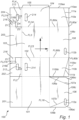
- a blank 100 for forming a package 200 comprising a set of four side wall panels; namely a first 101, a second 102, a third 103, and a fourth 104 side wall panel arranged in the blank 100 consecutively after each other along a longitudinal direction L and foldably connected to each other along fold lines extending in a transversal direction T.
- the blank 100 is configured to be folded at the fold line between the first side wall panel 101 and the second side wall panel 102 and at the fold line between the third side wall panel 103 and the fourth side wall panel 104 to be assembled to a flat-laid but assembled state.
- a fifth wall panel 105 is provided at a transversally extending side of the fourth side wall panel 104 and is attached to the first side wall panel 101 or vice versa. It may be attached using glue, staples, or any other kind of attachment method commonly used for paper-based materials. In this assembled, but still flat-laid configuration, the blank 100 is prepared to be easy to transport and store before use. It may be noted that in figures 1-2 , dashed lines typically represent fold lines and solid lines typically represents cut-lines where the material is cut and separated or perforation-lines where the material is perforated and intended to be separated.
- the blank 100 also comprises a first bottom panel 106 and a second bottom panel 108.
- Each bottom panel 106, 108 is foldably connected to the respective first side wall panel 101 and the third side wall panel 103 along fold lines extending in the longitudinal direction L.
- the first bottom panel 106 comprises two internal, inclined fold lines 107a-b.
- the internal, inclined fold lines 107a-b extend along a direction having a major component in the transverse direction T. Further, each of the internal, inclined fold lines extend from a respective transversally extending side 106a, 106b of the first bottom panel 106 to a free, longitudinally extending side 106c of the first bottom panel 106.
- the internal, inclined fold lines originate at each of the corners created by the fold line FL16 extending in the longitudinal direction L connecting the first side wall panel 101 to the first bottom panel 106 and each of the free transversally extending sides 106a, 106b. Further, the free corners 106ac, 106bc of the free longitudinally extending side of the first bottom panel 106 may be chamfered.
- the first bottom panel 106 comprises a cut-out 112a, configured to form a handle.
- the cut-out 112a preferably extends in the longitudinal direction L.
- the cut-out 112a may be positioned at a position across one of the internal, inclined fold lines 107b.
- the cut-out 112a may be positioned between the free corner 106ac of the free transversally extending side 106b and the free longitudinally extending side 106c and a centre point of the free longitudinally extending side 106c, and is preferably positioned closer to the free corner 106ac of the free transversally extending side 106b and the free longitudinally extending side 106c than to the centre point of the free longitudinally extending side 106c.
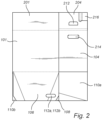
- Two opposing side wall portions 110a, 110b are each foldably connected to a respective transversally extending side of the second bottom panel 108.
- Each of the side wall portions 110a, 110b may be separate from or may be separably connected to the respective one of the second side wall panel 102 and fourth side wall panel 104, preferably by a perforated separation line. As shown in figure 2 , this configuration allows for the blank to be flat and facilitates securing that no parts extend from the blank 100 when the blank 100 is transported and before a first-time erection into a package 200.
- each of the side wall portions 110a, 110b comprises an internal, inclined fold line 111a, 111b extending in a direction having a major component in the longitudinal direction L.
- Each of the internal, inclined fold lines 111a, 111b extends from a longitudinally extending side 110ac, 110bc of the side wall portion 110a, 110b opposing the set of side wall panels 102, 104 to a free, transversally extending side 110aa, 110bb of the side wall portion 110a, 110b.
- each of the internal, inclined fold lines 111a, 111b of each of the side wall portion 110a, 110b originates at the free, outer end FL80a', FL80b' of each of the fold line FL80a, FL80b between the second bottom panel 108 and each side wall portion 110a, 110b.
- the second bottom panel 108 may comprise a cut-out 112b configured to form a handle.
- the cut-out 112b preferably extends in the longitudinal direction L.
- the cut-out 112b may be positioned between a fold line FL80b to the side wall portion 110b and a centre point of a free longitudinally extending side 108c of the second bottom panel 108.
- the cut-out 112b is preferably positioned closer to the fold line FL80b to the side wall portion 110b than to the centre point of the free longitudinally extending side 108c of the second bottom panel 108.
- the second side wall panel 102 and fourth side wall panel 104 may comprise a cut-out 214 configured to form a handle.
- the cut-out 214 preferably extends in the longitudinal direction L.
- the locking flap 105 at the free transversally extending side of the fourth side wall panel 104 may be attached to the free transversally extending side of the first side wall panel 101. This may be accomplished by e.g. using glue or any other adhesive or by mechanical attachment such as by stapling. The result is a flat-laid intermediate state as shown in figure 2 .
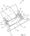
- Figure 3 shows the blank being erected to a package 200.
- the first side wall panel 101 becomes positioned opposite to the third side wall panel 103
- the second side wall panel 102 becomes positioned opposite to the fourth side wall panel 104 whereby the side wall panels 101, 102, 103, 104 define the package volume.
- the first bottom panel 106 is folded into the package volume relative to the first side wall panel 101.
- the side wall portions 110a, 110b are folded relative to the second bottom panel 108 and moved towards the volume of the package 200 by folding the second bottom panel 108 relative to the third side wall panel 103 using the cut-out 112b as a handle.
- the side wall portions 110a, 110b are folded relative to the second bottom panel 108 such that the side wall portions 110a, 110b becomes positioned parallel to the respective inside of the second side wall panel 102 and the fourth side wall panel 104.
- the first bottom panel 106 is folded back downwardly towards the second bottom panel 108, wherein each internal, inclined fold line 107a, 107b of the first bottom panel 106 are folded so as to form flaps created from folding pointing towards the inside of the first side wall panel 101, thereby facilitating passage of the first bottom panel 106 between the side wall portions 110a, 110b extending alongside the insides of the second and fourth side walls 102, 104.
- Folding the side wall portions 110a, 110b at their respective internal, inclined fold lines 111a, 111b such that the outer flaps created from folding are pointing towards the second side wall panel 102 and fourth side wall panel 104 facilitates folding the first bottom panel 106 down into the volume and further down to be placed on top of the second bottom panel 108.
- the package is designed to be erected using the above described procedure.
- the procedure is explained in more detail below.
- Figure 5 discloses the state of the package after step vii (01-04) has been completed. It may be noted that the package may be left in this position.
- first bottom panel 106 is allowed to lean inwardly into the volume such that it is easily accessible. Furthermore, it is e.g. no longer necessary for the user to position the side wall portions 110a, 110b tightly against the side wall panels 102, 104 before first bottom panel 106 can be folded down into its final position.
- the side wall portions 110a, 110b are provided with fold lines 111a, 111b.
- the fold lines 111a, 111b are oriented with a major component in the longitudinal direction L, which results in that there are formed inwardly extending flaps formed by the portions outside the fold lines 111a, 111b that can interact with the flaps of the first bottom panel 106.
- the inwardly extending flaps will also automatically push the side wall portions 110a, 110b outwardly against the side wall panels 102, 104 directly when the first bottom panel 106 is folded downwardly which in a sense directly corrects any non-correct positioning of the side wall portions 110a, 110b.
- the longitudinal extension of the side wall portions 110a, 110b is such that the free ends 110aa, 110bb essentially coextends with the fold lines between the first and fourth side wall panels 101, 104 respectively between the first and second side wall panels 101, 102.
- the bottom panels 106, 108 and the side wall portions 110a, 110b have free ends 106c, 108c, 110ac, 110bc extending at a transversal distance from the first, second, third and fourth side wall panels 101, 102, 103, 104 essentially being equal to or marginally smaller than the longitudinal extension of the second and fourth side wall panels 102, 104 such that the bottom panels 106, 108 and the side wall portions 11 0a, 110b may be folded into the volume of the package 200 and still cover the bottom and form stable connections between the side wall panels 101, 103.
- the blank 100 may be made of a paper-based material.
- the blank 100 is made of a corrugated cardboard material.
- Paper-based material will provide a light weight package, yet suitable for carrying heavy loads.
- a package 200 as disclosed made of paper-based material, a mechanically stable package may be provided.
- the paper-based material such as a corrugated cardboard material, may provide a blank 100 that is easy to erect and easy to transport to the point of use.
- a blank 100 of a paper-based material, such as a corrugated cardboard material is typically environmentally friendly and can be recycled in a simple manner.
- the blank 100 may further comprise a set of top panels.
- the set of top panels comprises a first, second, third and a fourth top panel 201, 202, 203, 204.
- Each top panel 201, 202, 203, 204 is foldably connected to an associated side wall panel 101, 102, 103, 104.
- the third top panel 203 comprises two locking flaps 216.
- Each locking flap 216 is connected to a respective transversally extending side of the third top panel 203 and is foldable relative to the third top panel 203 along fold lines extending in the transverse direction T.
- Each locking flap 216 has a longitudinal extension from the third top panel 203 past an extension of the fold line FL23 between the third side wall panel 103 and the second side wall panel 102, respectively past an extension of the fold line FL34 between the third side wall panel 103 and the fourth side wall panel 104.
- FIG. 3 discloses the package during erection of the blank 100
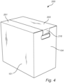
- Fig 4 discloses the package 200 in the closed state.
- the package 200 is configured to be put in a closed state by folding the first and third top panels 201, 203 such that the third top panel 203 is configured to at least party overlap and is positioned above the first top panel 201, and by folding the locking flaps 216 into the cut-outs 214, 212.
- the locking flaps 216 are folded inwards into the cut-outs, and then preferably also folded relative to the respective side wall panel 102, 104 in an upward motion.
- the locking flaps 216 form an upper, smooth part of the handle and also locks the package 200 in the closed state.
- the third top panel 203 partly overlaps the first top panel 201. It may be noted that the third top panel 203 only presents a single edge whereby an almost flat exterior of the top of the package 200 is formed when the package 200 is in the closed state.
- the package is easily stackable, and there is a reduced risk of packages catching the flaps or panels of other packages during stacking and handling, which would increase the risk of unintentional opening of packages or unintentional damaging of packages or increase the risk of incorrect relative positioning when stacking the packages.
- Each locking flap 216 may comprise an internal fold line FL216 having an extension in the transverse direction T.
- the internal fold line FL216 may provide the locking flap 216 with an outer part 216b.
- the locking flap 216 is configured to be folded inwards such that the outer part 216b may be folded into the cut-outs 212, 214 forming the handle and thereby lock the package 200 in the closed state.
- the outer portion 216b preferably has an extension in the transverse direction T being greater than the rest of the locking flap 216, at least wider than the part of the locking flap 216 where the internal fold line FL216 is provided.
- the internal fold line FL216 is preferably formed of more than one parallel fold line to allow the part of the locking panel 216 being provided with the internal fold lines 216 to be folded into the cut-outs 212, 214 and to allow the outer part 216b to be folded upwardly alongside the inner side of the respective second and fourth top panel 202, 204.
- each locking flap 216 may be cut from a geometrical rectangular extension of the respective second and fourth top panel 202, 204.
- the cut-out 214 of the second and fourth side wall panels 102, 104 may each have a shape corresponding to the shape of the associated cut-out 212 of the respective second and fourth top panel 202, 204.
- the cut-outs 214 of the second and fourth side wall panels 102, 104 may be wider than the cut-out 212 of the respective second and fourth top panel 202, 204.
- the outer part 216b of the locking flap can easily pass through the cut-out 214 of the respective second and fourth side wall panels 102, 104, and lock relative to the cut-out 212 of the respective second and fourth top panel 202, 204.
- the cut-outs 214 forming a handle of the side wall panels may be partially a cut-out comprising a fold line on a side facing the second respective fourth top panel 202, 204.
- the partly cut-out 214 may be folded inwards when the package 200 is erected to form a mechanical locking mechanism between the respective second or fourth side wall panel 102, 104 and the respective second or fourth top panel 202, 204.
- the longitudinal extension of the locking flap 216 past the extension of the fold line FL23 between the third side wall panel 103 and the second side wall panel 102 and the internal fold line FL216 of the locking flap 216, respectively the longitudinal extension of the locking flap 216 past the extension of the fold line FL34 between the third side wall panel 103 and the fourth side wall panel 104 and the internal fold line FL216 of the locking flap 216 may be defined as a first distance D1.
- a distance between the cut-out 212 in the second top panel 202 and the fold line FL2 between the second side wall panel 102 and the second top panel 202, respectively a distance between the cut-out 212 of the fourth top panel 204 and the fold line FL4 between the fourth side wall panel 104 and the fourth top panel 204 may be defined as a second distance D2.
- the first distance D1 may correspond to the second distance D2. It is preferred that the first distance D1 is equal to the second distance D2. By such a design, the internal fold line FL216 of the locking flap 216 becomes folded about an edge of the cut-out 212 when erecting the package. By the first distance D1 being equal to the second distance D2, the locking mechanism of the locking flap 216 may be provided having a high mechanical stability.
- a distance between the fold line FL3 between the third side wall panel 103 and the third top panel 203 and a longitudinally extending side of the locking flap 216 facing the third side wall panel 103 may define a third distance D3.
- a distance between the cut-out 212 of the second top panel 202 and the extension of the fold line FL23 between the third side wall panel 103 and the second side wall panel 102, respectively a distance between the cut-out 212 of the fourth top panel 204 and the extension of the fold line FL34 between the third side wall panel 103 and the fourth side wall panel 104 may define a fourth distance D4.
- the third distance D3 may correspond to the fourth distance D4. It is preferred that the third distance D3 is equal to the fourth distance D4.
- the locking tab 216 may be snugly inserted around an edge of the cut-outs 212 facing the third top panel 103 when the package 200 is about to be put in a closed state.
- the side wall portions 11 0a, 110b may for instance comprise a cut-out preferably extending in the transversal direction T.
- the cut-out may be placed centrally on the side wall portion as seen along the free transversally extending side of each side wall portion.
- the cut-out of the side wall portions 110a, 110b may be configured such that each coincide with the respective cut-out 214 of the second side wall panel 102 and fourth side wall panel 104. This configuration allows the bottom part to, in a sense, be locked to the side walls, thereby further increasing the strength of the package 200.
- cut-out 214 is positioned fairly low on the respective side wall panel 102, 104 such that the longitudinal extension of the respective side wall portion 110a, 110b, as seen in a flat-laid state of the blank 100, is such that the side wall portions 110a, 110b will extend upwardly along the inside of the respective side wall 102, 104 to a height above the cut-outs 214 when the blank 100 is folded into a package 200.
- the cut-outs 214 are provided fairly high compared to the longitudinal extension of the side wall portions 110a, 110b such that the side wall portions 110a, 110b will not reach the cut-outs 214 when the blank 100 is folded into a package 200.
Landscapes
- Engineering & Computer Science (AREA)
- Mechanical Engineering (AREA)
- Cartons (AREA)
Claims (15)
- Zuschnitt (100) zum Bilden einer Verpackung (200), der Zuschnitt (100) umfassend:einen Satz von Seitenwandplatten, umfassend eine erste, zweite, dritte und vierte Seitenwandplatte (101, 102, 103, 104), die entlang einer Längsrichtung (L) hintereinander angeordnet und entlang sich in Querrichtung (T) erstreckender Faltlinien faltbar miteinander verbunden sind,eine erste Bodenplatte (106), die entlang einer sich in Längsrichtung (L) erstreckenden Faltlinie faltbar mit der ersten Seitenwandplatte (101) verbunden ist,eine zweite Bodenplatte (108), die faltbar mit der dritten Seitenwandplatte (103) entlang einer Faltlinie verbunden ist, die sich in der Längsrichtung (L) erstreckt, wobei die zweite Bodenplatte (108) ausgebildet ist, um unter der ersten Bodenplatte (106) positioniert zu werden, wenn der Zuschnitt (100) zu einer Verpackung (200) aufgerichtet wurde, undzwei gegenüberliegende Seitenwandabschnitte (110a, 110b), die jeweils mit einer entsprechenden sich quer erstreckenden Seite der zweiten Bodenplatte (108) faltbar verbunden sind,und wobei die zweite Bodenplatte (108) derart ausgebildet ist, dass bei dem Aufrichten des Zuschnitts (100) zu einer Verpackung (200) die Seitenwandabschnitte (110a, 110b) relativ zu der zweiten Bodenplatte (108) gefaltet werden und zusammen mit der entsprechenden zweiten (102) und vierten (104) Seitenwandplatte zwei gegenüberliegende doppelwandige Seitenwände bilden, dadurch gekennzeichnet, dassdie erste Bodenplatte (106) zwei innere, schräge Faltlinien (107a, 107b) umfasst, wobei sich jede innere, schräge Faltlinie (107a, 107b) entlang einer Richtung erstreckt, die eine Hauptkomponente in der Querrichtung (T) aufweist, und wobei sich jede innere, schräge Faltlinie (107a, 107b) von einer sich quer erstreckenden Seite (106a, 106b) der ersten Bodenplatte (106) zu einer sich längs erstreckenden freien Seite (106c) der ersten Bodenplatte (106) erstreckt,wobei jeder Seitenwandabschnitt (110a, 110b) eine innere, schräge Faltlinie (111a, 111b) umfasst, die sich in einer Richtung erstreckt, die eine Hauptkomponente in der Längsrichtung (L) aufweist, wobei sich jede innere, schräge Faltlinie (111a, 111b) von einer sich längs erstreckenden Seite (110ac, 110bc) des Seitenwandabschnitts (110a, 110b), die dem Satz von Seitenwandplatten (101-104) gegenüberliegt, zu einer entsprechenden sich quer erstreckenden freien Seite (110aa, 110bb) des entsprechenden Seitenwandabschnitts (110a, 110b) erstreckt.
- Zuschnitt (100) nach Anspruch 1, wobei zumindest eine, vorzugsweise jede, der inneren, schrägen Faltlinien (107a, 107b) der ersten Bodenplatte (106) an einer entsprechenden einen der Ecken beginnt, die durch die sich in Längsrichtung (L) erstreckende Faltlinie (FL16), die die erste Seitenwandplatte (101) mit der ersten Bodenplatte (106) verbindet, und die entsprechende eine der sich quer erstreckenden freien Seiten (106a, 106b) erzeugt wird.
- Zuschnitt (100) nach einem der Ansprüche 1 bis 2, wobei zumindest eine, vorzugsweise jede, der inneren, schrägen Faltlinien (111a, 111b) jedes der Seitenwandabschnitte (110a, 110b) an einem freien, äußeren Ende (FL80a', FL80b') einer entsprechenden einen der Faltlinien (FL80a, FL80b) zwischen der zweiten Bodenplatte (108) und einem entsprechenden einen der Seitenwandabschnitte (110a, 110b) beginnt.
- Zuschnitt (100) nach einem der Ansprüche 1 bis 3, wobei die erste Bodenplatte (106) mit einem zum Bilden eines Griffs ausgebildeten Ausschnitt (112a) vorgesehen ist, wobei sich der Ausschnitt (112a) vorzugsweise in Längsrichtung (L) erstreckt.
- Zuschnitt (100) nach Anspruch 4, wobei der Ausschnitt (112a) in der ersten Bodenplatte (106) über eine der inneren, schrägen Faltlinien (107b) positioniert ist.
- Zuschnitt (100) nach Anspruch 4 oder 5, wobei der Ausschnitt (112a) zwischen einer freien Ecke (106ac) einer sich quer erstreckenden freien Seite (106b) und einer sich längs erstreckenden freien Seite (106c) und einem Mittelpunkt der sich längs erstreckenden freien Seite (106c) positioniert ist, vorzugsweise näher an der freien Ecke (106ac) als an dem Mittelpunkt der sich längs erstreckenden freien Seite (106c).
- Zuschnitt (100) nach einem der Ansprüche 1 bis 6, wobei die zweite Bodenplatte (108) mit einem zum Bilden eines Griffs ausgebildeten Ausschnitt (112b) vorgesehen ist, wobei sich der Ausschnitt (112b) bevorzugt in der Längsrichtung (L) erstreckt.
- Zuschnitt (100) nach Anspruch 7, wobei der Ausschnitt (112b) in der zweiten Bodenplatte (108) zwischen einer Faltlinie (FL80b) zu dem Seitenwandabschnitt (110b) und einem Mittelpunkt einer sich längs erstreckenden freien Seite (108c) der zweiten Bodenplatte (108) positioniert ist, vorzugsweise näher an der Faltlinie (FL80b) zu dem Seitenwandabschnitt (110b) als an dem Mittelpunkt der sich längs erstreckenden freien Seite (108c) der zweiten Bodenplatte (108).
- Zuschnitt (100) nach einem der Ansprüche 1 bis 8, wobei jeder Seitenwandabschnitt (110a, 110b) mit einer entsprechenden Seitenwandplatte der zweiten (102) und vierten (104) Seitenwandplatte trennbar verbunden ist, vorzugsweise durch eine perforierte Trennlinie.
- Zuschnitt (100) nach einem der Ansprüche 1 bis 9, wobei der Zuschnitt (100) aus einem papierbasierten Material, bevorzugt aus einem Wellkartonmaterial, hergestellt ist.
- Zuschnitt (100) nach einem der Ansprüche 1 bis 10, wobei der Zuschnitt (100) ferner umfasst:einen Satz von Deckplatten, umfassend eine erste, zweite, dritte und vierte Deckplatte (201, 202, 203, 204), wobei jede Deckplatte (201, 202, 203, 204) faltbar mit einer zugehörigen Seitenwandplatte (101, 102, 103, 104) verbunden ist,wobei die zweite und vierte Seitenwandplatte (102, 104) jeweils einen zum Bilden eines Griffs in der Seitenwandplatte (102, 104) ausgebildeten Ausschnitt (214) umfasst,wobei die entsprechenden zweiten und vierten Deckplatten (202, 204) jeweils einen Ausschnitt (212) umfassen,wobei, wenn der Zuschnitt (100) zu einer Verpackung (200) aufgerichtet ist, die zweite und die vierte Deckplatte (202, 204) relativ zu der zweiten und der vierten Seitenwandplatte (102, 104) so gefaltet werden, dass der Ausschnitt (214) der entsprechenden Seitenwandplatte (102, 104) und der Ausschnitt (212) der zugehörigen Deckplatte (202, 204) sich überlappen und zusammen einen Griff bilden,wobei die dritte Deckplatte (203) zwei Verriegelungsklappen (216) umfasst, wobei jede Verriegelungsklappe (216) mit einer entsprechenden sich quer erstreckenden Seite der dritten Deckplatte (203) verbunden ist und relativ zu der dritten Deckplatte (203) entlang sich in der Querrichtung (T) erstreckenden Faltlinien faltbar ist, wobei jede Verriegelungsklappe (216) eine Längserstreckung von der dritten Deckplatte (203) über eine Erstreckung der Faltlinie (FL23) zwischen der dritten Seitenwandplatte (103) und der zweiten Seitenwandplatte (102) bzw. über eine Erstreckung der Faltlinie (FL34) zwischen der dritten Seitenwandplatte (103) und der vierten Seitenwandplatte (104) aufweist,wobei, wenn der Zuschnitt (100) zu einer Verpackung (200) aufgerichtet ist, die Verpackung (200) ausgebildet ist, um durch Falten der ersten und dritten Deckplatte (201, 203), sodass die dritte Deckplatte (203) ausgebildet ist, um zumindest teilweise zu überlappen und über der ersten Deckplatte (201) positioniert zu werden, und durch Falten der Verriegelungsklappen (216) in die den Griff bildenden Ausschnitte (214, 212) und dadurch Verriegeln der Verpackung (200) in einem geschlossenen Zustand in einen geschlossenen Zustand gebracht zu werden.
- Zuschnitt (100) nach Anspruch 11, wobei jede Verriegelungsklappe (216) eine innere Faltlinie (FL216) umfasst, die eine Erstreckung in der Querrichtung (T) aufweist und ausgebildet ist, dass sie, wenn der Zuschnitt (100) zu der Verpackung (200) aufgerichtet wurde, nach innen gefaltet wird, sodass ein äußerer Teil (216b) zum Falten in die den Griff bildenden Ausschnitte ausgebildet ist und dadurch die Verpackung (200) in dem geschlossenen Zustand verriegelt.
- Zuschnitt (100) nach Anspruch 12, wobei ein erster Abstand (D1) durch die Längserstreckung der Verriegelungsklappe (216) über die Erstreckung der Faltlinie (FL23) zwischen der dritten Seitenwandplatte (103) und der zweiten Seitenwandplatte (102) und die innere Faltlinie (FL216) der Verriegelungsklappe (216) bzw. der Längserstreckung der Verriegelungsklappe (216) über die Erstreckung der Faltlinie (FL34) zwischen der dritten Seitenwandplatte (103) und der vierten Seitenwandplatte (104) und der inneren Faltlinie (FL216) der Verriegelungsklappe (216) definiert ist,wobei ein zweiter Abstand (D2) durch einen Abstand zwischen dem Ausschnitt (212) in der zweiten Deckplatte (202) und der Faltlinie (FL2) zwischen der zweiten Seitenwandplatte (102) und der zweiten Deckplatte (202) bzw. einen Abstand zwischen dem Ausschnitt (212) der vierten Deckplatte (204) und der Faltlinie (FL4) zwischen der vierten Seitenwandplatte (104) und der vierten Deckplatte (204) definiert ist, undwobei der erste Abstand (D1) dem zweiten Abstand (D2) entspricht und diesem vorzugsweise gleich ist.
- Zuschnitt (100) nach einem der Ansprüche 11 bis 13, wobei ein dritter Abstand (D3) durch einen Abstand zwischen der Faltlinie (FL3) zwischen der dritten Seitenwandplatte (103) und der dritten Deckplatte (203) und einer sich längs erstreckenden Seite der Verriegelungsklappe (216), die der dritten Seitenwandplatte (103) zugewandt ist, definiert ist undwobei ein vierter Abstand (D4) durch einen Abstand zwischen dem Ausschnitt (212) der zweiten Deckplatte (202) und der Erstreckung der Faltlinie (FL23) zwischen der dritten Seitenwandplatte (103) und der zweiten Seitenwandplatte (102) bzw. durch einen Abstand zwischen dem Ausschnitt (212) der vierten Deckplatte (204) und der Erstreckung der Faltlinie (FL34) zwischen der dritten Seitenwandplatte (103) und der vierten Seitenwandplatte (104) definiert ist, undwobei der dritte Abstand (D3) dem vierten Abstand (D4) entspricht und diesem vorzugsweise gleich ist.
- Verpackung (200), die durch Aufrichten des Zuschnitts (100) nach einem der Ansprüche 1 bis 14 zu einer Verpackung (200) gebildet wird.
Applications Claiming Priority (2)
| Application Number | Priority Date | Filing Date | Title |
|---|---|---|---|
| SE1951379A SE543834C2 (en) | 2019-12-03 | 2019-12-03 | A blank for forming a package and a package |
| PCT/IB2020/061187 WO2021111260A1 (en) | 2019-12-03 | 2020-11-26 | A blank for forming a package and a package |
Publications (4)
| Publication Number | Publication Date |
|---|---|
| EP4069597A1 EP4069597A1 (de) | 2022-10-12 |
| EP4069597A4 EP4069597A4 (de) | 2024-01-17 |
| EP4069597B1 true EP4069597B1 (de) | 2025-01-08 |
| EP4069597C0 EP4069597C0 (de) | 2025-01-08 |
Family
ID=76222341
Family Applications (1)
| Application Number | Title | Priority Date | Filing Date |
|---|---|---|---|
| EP20895703.5A Active EP4069597B1 (de) | 2019-12-03 | 2020-11-26 | Zuschnitt zur herstellung einer verpackung und verpackung |
Country Status (4)
| Country | Link |
|---|---|
| EP (1) | EP4069597B1 (de) |
| PL (1) | PL4069597T3 (de) |
| SE (1) | SE543834C2 (de) |
| WO (1) | WO2021111260A1 (de) |
Family Cites Families (16)
| Publication number | Priority date | Publication date | Assignee | Title |
|---|---|---|---|---|
| US2757849A (en) * | 1955-02-01 | 1956-08-07 | Container Corp | Container unit and carrier for multiple units |
| JPS4416204Y1 (de) * | 1966-09-20 | 1969-07-12 | ||
| US3667666A (en) * | 1970-12-30 | 1972-06-06 | Perma Products Co | Foldable storage box |
| JPS56144718U (de) * | 1980-03-31 | 1981-10-31 | ||
| JPH053118U (ja) * | 1991-06-25 | 1993-01-19 | レンゴー株式会社 | 包装箱 |
| US6135347A (en) * | 1997-09-24 | 2000-10-24 | Mueller; Charles J. | Transportable container with press closure |
| US6149052A (en) * | 1997-09-24 | 2000-11-21 | Mueller; Charles J. | Rapid assembly box with two-part adhesive bottom |
| US5887782A (en) * | 1997-09-24 | 1999-03-30 | Mueller; Charles J. | High stacking strength automatic corrugated box |
| DE29820547U1 (de) * | 1998-11-17 | 1999-04-22 | Nips Ordnungssysteme GmbH, 93055 Regensburg | Vielseitig verwendbare Faltschachtel |
| DE29901162U1 (de) * | 1999-01-19 | 1999-05-12 | Stone Europa Carton AG, 20095 Hamburg | Zuschnitt aus faltbarem Material zum Auffalten eines tragfähigen Transportbehältnisses |
| FR2867751B1 (fr) * | 2004-03-18 | 2006-07-07 | Smurfit Socar Sa | Emballage en un materiau semi-rigide comportant un temoin d'inviolabilite |
| US20080083822A1 (en) * | 2006-10-06 | 2008-04-10 | Fellowes, Inc. | Record storage box and mailer |
| EP2539234A4 (de) * | 2010-02-26 | 2015-04-29 | Fellowes Inc | Lagerungskiste mit integriertem deckel mit verschlussklappen |
| US8746544B2 (en) * | 2012-07-20 | 2014-06-10 | Brand Design Company, Inc. | Collapsible box and lid assembly |
| DE202019100562U1 (de) * | 2019-01-30 | 2019-05-06 | Progress Packaging Gmbh | Transportverpackung mit stabilem Boden |
| DE202019100561U1 (de) * | 2019-01-30 | 2019-05-06 | Progress Packaging Gmbh | Transportverpackung mit separatem Deckel |
-
2019
- 2019-12-03 SE SE1951379A patent/SE543834C2/en unknown
-
2020
- 2020-11-26 WO PCT/IB2020/061187 patent/WO2021111260A1/en not_active Ceased
- 2020-11-26 PL PL20895703.5T patent/PL4069597T3/pl unknown
- 2020-11-26 EP EP20895703.5A patent/EP4069597B1/de active Active
Also Published As
| Publication number | Publication date |
|---|---|
| SE543834C2 (en) | 2021-08-03 |
| EP4069597A4 (de) | 2024-01-17 |
| SE1951379A1 (en) | 2021-06-04 |
| PL4069597T3 (pl) | 2025-03-31 |
| EP4069597A1 (de) | 2022-10-12 |
| WO2021111260A1 (en) | 2021-06-10 |
| EP4069597C0 (de) | 2025-01-08 |
Similar Documents
| Publication | Publication Date | Title |
|---|---|---|
| US6098873A (en) | One piece folded and glued container with tabbed columns | |
| CN101253098B (zh) | 具有自锁角片折叠底折片的八角形散装箱 | |
| US5588585A (en) | Automatic set-up carton with corner posts | |
| US6116498A (en) | Stackable open-top container | |
| US6364200B1 (en) | Bulk box with quick-lock bottom and set-up feature | |
| US6688514B2 (en) | Bulk box with a quick lock bottom and smooth interior bottom surface | |
| US6527167B1 (en) | One piece folded and glued container | |
| CN100509573C (zh) | 运货箱和托架的组件以及运货箱 | |
| US20100101977A1 (en) | Stackable Packaging For Lipped Containers | |
| EP1015328A1 (de) | Siegelbare faltschachtel | |
| US6220508B1 (en) | Quick-lock open-bottom bulk box with easy set-up feature | |
| US5294043A (en) | Product carton | |
| US6427906B2 (en) | Collapsible box | |
| EP4069597B1 (de) | Zuschnitt zur herstellung einer verpackung und verpackung | |
| WO2021111261A1 (en) | Blank for forming a package and a package | |
| EP4118000A1 (de) | Satz aus zuschnitten, schachtelzuschnitt und deckelzuschnitt | |
| US20010010326A1 (en) | Sealable carton | |
| CA2370334C (en) | One piece folded and glued container | |
| WO2022130199A1 (en) | Blank configured to be erected into a box, and a box formed of such blank | |
| GB2049630A (en) | Box Made of Cardboard or Like Material | |
| EP4269263A1 (de) | Zuschnitt | |
| GB2164922A (en) | Carton | |
| EP2108598A1 (de) | Bag-in-Box-Verpackungssystem für fließfähiges Schüttgut |
Legal Events
| Date | Code | Title | Description |
|---|---|---|---|
| STAA | Information on the status of an ep patent application or granted ep patent |
Free format text: STATUS: THE INTERNATIONAL PUBLICATION HAS BEEN MADE |
|
| PUAI | Public reference made under article 153(3) epc to a published international application that has entered the european phase |
Free format text: ORIGINAL CODE: 0009012 |
|
| STAA | Information on the status of an ep patent application or granted ep patent |
Free format text: STATUS: REQUEST FOR EXAMINATION WAS MADE |
|
| 17P | Request for examination filed |
Effective date: 20220704 |
|
| AK | Designated contracting states |
Kind code of ref document: A1 Designated state(s): AL AT BE BG CH CY CZ DE DK EE ES FI FR GB GR HR HU IE IS IT LI LT LU LV MC MK MT NL NO PL PT RO RS SE SI SK SM TR |
|
| DAV | Request for validation of the european patent (deleted) | ||
| DAX | Request for extension of the european patent (deleted) | ||
| A4 | Supplementary search report drawn up and despatched |
Effective date: 20231218 |
|
| RIC1 | Information provided on ipc code assigned before grant |
Ipc: B65D 5/66 20060101ALI20231212BHEP Ipc: B65D 5/468 20060101ALI20231212BHEP Ipc: B65D 5/10 20060101ALI20231212BHEP Ipc: B65D 5/02 20060101ALI20231212BHEP Ipc: B65D 5/36 20060101AFI20231212BHEP |
|
| GRAP | Despatch of communication of intention to grant a patent |
Free format text: ORIGINAL CODE: EPIDOSNIGR1 |
|
| STAA | Information on the status of an ep patent application or granted ep patent |
Free format text: STATUS: GRANT OF PATENT IS INTENDED |
|
| INTG | Intention to grant announced |
Effective date: 20240716 |
|
| GRAS | Grant fee paid |
Free format text: ORIGINAL CODE: EPIDOSNIGR3 |
|
| GRAA | (expected) grant |
Free format text: ORIGINAL CODE: 0009210 |
|
| STAA | Information on the status of an ep patent application or granted ep patent |
Free format text: STATUS: THE PATENT HAS BEEN GRANTED |
|
| AK | Designated contracting states |
Kind code of ref document: B1 Designated state(s): AL AT BE BG CH CY CZ DE DK EE ES FI FR GB GR HR HU IE IS IT LI LT LU LV MC MK MT NL NO PL PT RO RS SE SI SK SM TR |
|
| REG | Reference to a national code |
Ref country code: GB Ref legal event code: FG4D |
|
| REG | Reference to a national code |
Ref country code: CH Ref legal event code: EP |
|
| REG | Reference to a national code |
Ref country code: DE Ref legal event code: R096 Ref document number: 602020044661 Country of ref document: DE |
|
| REG | Reference to a national code |
Ref country code: IE Ref legal event code: FG4D |
|
| U01 | Request for unitary effect filed |
Effective date: 20250129 |
|
| U07 | Unitary effect registered |
Designated state(s): AT BE BG DE DK EE FI FR IT LT LU LV MT NL PT RO SE SI Effective date: 20250205 |
|
| PG25 | Lapsed in a contracting state [announced via postgrant information from national office to epo] |
Ref country code: RS Free format text: LAPSE BECAUSE OF FAILURE TO SUBMIT A TRANSLATION OF THE DESCRIPTION OR TO PAY THE FEE WITHIN THE PRESCRIBED TIME-LIMIT Effective date: 20250408 |
|
| PG25 | Lapsed in a contracting state [announced via postgrant information from national office to epo] |
Ref country code: ES Free format text: LAPSE BECAUSE OF FAILURE TO SUBMIT A TRANSLATION OF THE DESCRIPTION OR TO PAY THE FEE WITHIN THE PRESCRIBED TIME-LIMIT Effective date: 20250108 |
|
| PG25 | Lapsed in a contracting state [announced via postgrant information from national office to epo] |
Ref country code: NO Free format text: LAPSE BECAUSE OF FAILURE TO SUBMIT A TRANSLATION OF THE DESCRIPTION OR TO PAY THE FEE WITHIN THE PRESCRIBED TIME-LIMIT Effective date: 20250408 Ref country code: IS Free format text: LAPSE BECAUSE OF FAILURE TO SUBMIT A TRANSLATION OF THE DESCRIPTION OR TO PAY THE FEE WITHIN THE PRESCRIBED TIME-LIMIT Effective date: 20250508 |
|
| PG25 | Lapsed in a contracting state [announced via postgrant information from national office to epo] |
Ref country code: HR Free format text: LAPSE BECAUSE OF FAILURE TO SUBMIT A TRANSLATION OF THE DESCRIPTION OR TO PAY THE FEE WITHIN THE PRESCRIBED TIME-LIMIT Effective date: 20250108 |
|
| PG25 | Lapsed in a contracting state [announced via postgrant information from national office to epo] |
Ref country code: GR Free format text: LAPSE BECAUSE OF FAILURE TO SUBMIT A TRANSLATION OF THE DESCRIPTION OR TO PAY THE FEE WITHIN THE PRESCRIBED TIME-LIMIT Effective date: 20250409 |
|
| PG25 | Lapsed in a contracting state [announced via postgrant information from national office to epo] |
Ref country code: SM Free format text: LAPSE BECAUSE OF FAILURE TO SUBMIT A TRANSLATION OF THE DESCRIPTION OR TO PAY THE FEE WITHIN THE PRESCRIBED TIME-LIMIT Effective date: 20250108 |
|
| PG25 | Lapsed in a contracting state [announced via postgrant information from national office to epo] |
Ref country code: CZ Free format text: LAPSE BECAUSE OF FAILURE TO SUBMIT A TRANSLATION OF THE DESCRIPTION OR TO PAY THE FEE WITHIN THE PRESCRIBED TIME-LIMIT Effective date: 20250108 |
|
| PG25 | Lapsed in a contracting state [announced via postgrant information from national office to epo] |
Ref country code: SK Free format text: LAPSE BECAUSE OF FAILURE TO SUBMIT A TRANSLATION OF THE DESCRIPTION OR TO PAY THE FEE WITHIN THE PRESCRIBED TIME-LIMIT Effective date: 20250108 |
|
| PLBE | No opposition filed within time limit |
Free format text: ORIGINAL CODE: 0009261 |
|
| STAA | Information on the status of an ep patent application or granted ep patent |
Free format text: STATUS: NO OPPOSITION FILED WITHIN TIME LIMIT |
|
| 26N | No opposition filed |
Effective date: 20251009 |
|
| U20 | Renewal fee for the european patent with unitary effect paid |
Year of fee payment: 6 Effective date: 20251201 |
|
| PGFP | Annual fee paid to national office [announced via postgrant information from national office to epo] |
Ref country code: GB Payment date: 20251022 Year of fee payment: 6 |
|
| PGFP | Annual fee paid to national office [announced via postgrant information from national office to epo] |
Ref country code: PL Payment date: 20251105 Year of fee payment: 6 |