EP4069586B1 - Unbemanntes luftfahrzeug - Google Patents
Unbemanntes luftfahrzeug Download PDFInfo
- Publication number
- EP4069586B1 EP4069586B1 EP19856473.4A EP19856473A EP4069586B1 EP 4069586 B1 EP4069586 B1 EP 4069586B1 EP 19856473 A EP19856473 A EP 19856473A EP 4069586 B1 EP4069586 B1 EP 4069586B1
- Authority
- EP
- European Patent Office
- Prior art keywords
- unmanned aerial
- load
- aerial vehicle
- flight
- thrust
- Prior art date
- Legal status (The legal status is an assumption and is not a legal conclusion. Google has not performed a legal analysis and makes no representation as to the accuracy of the status listed.)
- Active
Links
Images


Classifications
-
- B—PERFORMING OPERATIONS; TRANSPORTING
- B64—AIRCRAFT; AVIATION; COSMONAUTICS
- B64D—EQUIPMENT FOR FITTING IN OR TO AIRCRAFT; FLIGHT SUITS; PARACHUTES; ARRANGEMENT OR MOUNTING OF POWER PLANTS OR PROPULSION TRANSMISSIONS IN AIRCRAFT
- B64D1/00—Dropping, ejecting, releasing or receiving articles, liquids, or the like, in flight
- B64D1/22—Taking-up articles from earth's surface
-
- B—PERFORMING OPERATIONS; TRANSPORTING
- B64—AIRCRAFT; AVIATION; COSMONAUTICS
- B64C—AEROPLANES; HELICOPTERS
- B64C29/00—Aircraft capable of landing or taking-off vertically, e.g. vertical take-off and landing [VTOL] aircraft
- B64C29/0008—Aircraft capable of landing or taking-off vertically, e.g. vertical take-off and landing [VTOL] aircraft having its flight directional axis horizontal when grounded
- B64C29/0083—Aircraft capable of landing or taking-off vertically, e.g. vertical take-off and landing [VTOL] aircraft having its flight directional axis horizontal when grounded the lift during taking-off being created by several motors of different type
-
- B—PERFORMING OPERATIONS; TRANSPORTING
- B64—AIRCRAFT; AVIATION; COSMONAUTICS
- B64C—AEROPLANES; HELICOPTERS
- B64C39/00—Aircraft not otherwise provided for
- B64C39/02—Aircraft not otherwise provided for characterised by special use
- B64C39/024—Aircraft not otherwise provided for characterised by special use of the remote controlled vehicle type, i.e. RPV
-
- B—PERFORMING OPERATIONS; TRANSPORTING
- B64—AIRCRAFT; AVIATION; COSMONAUTICS
- B64U—UNMANNED AERIAL VEHICLES [UAV]; EQUIPMENT THEREFOR
- B64U10/00—Type of UAV
- B64U10/10—Rotorcrafts
- B64U10/13—Flying platforms
-
- B—PERFORMING OPERATIONS; TRANSPORTING
- B64—AIRCRAFT; AVIATION; COSMONAUTICS
- B64U—UNMANNED AERIAL VEHICLES [UAV]; EQUIPMENT THEREFOR
- B64U50/00—Propulsion; Power supply
- B64U50/10—Propulsion
- B64U50/12—Propulsion using turbine engines, e.g. turbojets or turbofans
-
- B—PERFORMING OPERATIONS; TRANSPORTING
- B64—AIRCRAFT; AVIATION; COSMONAUTICS
- B64U—UNMANNED AERIAL VEHICLES [UAV]; EQUIPMENT THEREFOR
- B64U50/00—Propulsion; Power supply
- B64U50/10—Propulsion
- B64U50/19—Propulsion using electrically powered motors
-
- B—PERFORMING OPERATIONS; TRANSPORTING
- B64—AIRCRAFT; AVIATION; COSMONAUTICS
- B64U—UNMANNED AERIAL VEHICLES [UAV]; EQUIPMENT THEREFOR
- B64U2101/00—UAVs specially adapted for particular uses or applications
- B64U2101/60—UAVs specially adapted for particular uses or applications for transporting passengers; for transporting goods other than weapons
-
- B—PERFORMING OPERATIONS; TRANSPORTING
- B64—AIRCRAFT; AVIATION; COSMONAUTICS
- B64U—UNMANNED AERIAL VEHICLES [UAV]; EQUIPMENT THEREFOR
- B64U2201/00—UAVs characterised by their flight controls
- B64U2201/10—UAVs characterised by their flight controls autonomous, i.e. by navigating independently from ground or air stations, e.g. by using inertial navigation systems [INS]
Definitions
- the present invention relates to an unmanned aerial vehicle which is designed to lift and carry heavy loads.
- loads of up to and exceeding 100 kg are anticipated.
- the vehicle may be able to carry such loads distances up to 10 km.
- Unmanned aerial vehicles are generally well known, and include drones, rotorcopters, quadcopters, octocopters and the like. Such vehicles are typically provided with an electric motor which drives one or more rotors. The electric motor allows good mobility and manoeuvrability. However, it is difficult to generate a large lift thrust with these conventional vehicles.
- lithium ion batteries are used as a source of electrical power for the electric motors.
- Such lithium ion batteries can store energy at approximately 2.5 MJ/kg. Therefore, the electrically driven rotors result in a relatively poor endurance and flight range for loads above a minimal weight.
- drones which are able to assist in heavy lifting. Such assistance may be useful in construction, military deployment or extraction and operations, rescue operations, commercial delivery, or the like.
- US 2007/057113 A1 discloses a system and method for a short take-off and landing or vertical take-off and landing aircraft that stores required take-off power in the form of primarily an electric fan engine, and secondarily in the form of an internal combustion engine.
- EP 2 881 324 A1 discloses methods and apparatus to cooperatively lift a payload.
- US 10 071 804 B1 discloses an unmanned aerial vehicle which can deliver a package to a delivery destination.
- An unmanned aerial vehicle according to a first embodiment of the present invention is provided according to claim 1.
- This unmanned aerial vehicle allows the electric flight rotors to be used for the high precision manoeuvrability required for general flight while the gas turbine propulsion system is used to provide lift for lifting a heavy load. This therefore allows the unmanned aerial vehicle to lift a heavy load while maintaining manoeuvrability during flight.
- the load system may comprise a plurality of gas turbine propulsion systems.
- a plurality of gas turbine propulsion systems can increase the amount of thrust available to lift the load.
- the gas turbine propulsion systems may be arranged with N-fold rotational symmetry in the plane of the flight rotors around a centre of the unmanned aerial vehicle, wherein N is the number of gas turbine propulsion systems.
- the rotational symmetry of the gas turbine propulsion systems allows these systems to balance one another and provide a force simply to aid in the lifting of the load which not affecting the flight of the unmanned aerial vehicle.
- Each gas propulsion system may be provided at an angle with respect to the thrust direction of the flight rotors. The angle directs the gas propulsion systems to counteract the load and not affect the flight of the vehicle. Additionally, the jet plume does not impinge upon any load being carried.
- Each gas turbine propulsion system may comprise a ducted fan for producing the additional thrust in the form of its exhaust gas jet. Thrust in the form of exhaust gas jet is a thrust to weight efficient manner of generating additional lift.
- the gas turbine propulsion system may comprise a turbojet; turbofan; or turboprop. These gas turbine propulsion systems are good methods to generate additional lift for a relatively low weight.
- the flight system may comprise two or more rotors, arranged at an outer periphery of the unmanned aerial vehicle, preferably the flight system comprises four or eight rotors. Having the rotors arranged around the periphery of the unmanned aerial vehicle allows for enhanced manoeuvrability of the vehicle.
- Each gas turbine propulsion system may be provided within a radius defined by the rotors. As the gas turbine propulsion systems is provided within the radius defined by the rotors the force it generates can be more easily balanced.
- the controller may comprise: a first control system configured to control the flight system; and a second control system configured to control the load system, wherein the first and second control systems are independent of one another.
- the flight system allows the flight system to be used for the high precision manoeuvrability required for flight while the load system is used to provide lift for lifting a heavy load. This therefore allows the unmanned aerial vehicle to lift a heavy load while maintaining manoeuvrability during flight.
- Separating the first and second control systems allows the controller to effectively and efficiently provide additional thrust when necessary to lift the device separate to the flight control system.
- the unmanned aerial vehicle further comprises: a load sensor in communication with the controller, the load sensor being configured to provide a signal indicative of the weight applied by a load attached to the connection point; wherein the controller is configured to control the load system in response to the signal indicative of the weight applied to the connection point.
- the controller may be configured to control the load system in a closed-loop control to balance the force provided by the load system and the weight applied to the connection point. By balancing the weights the flight control system can operate as if the additional weight is not attached.
- the unmanned aerial vehicle may have a first mode of operation in which the flight system is operated to take-off and/or land the unmanned aerial vehicle and in which the load system in inactive.
- FOD foreign object damage
- the unmanned aerial vehicle may further have a second mode of operation in which the load system is activated to provide thrust equal to the weight of a load, and in which the flight system is used to generate thrust to manoeuvre the unmanned aerial vehicle and load.
- the load system thus counters the weight of the load and the flight system can simply be used to fly the unmanned aerial vehicle.
- the cargo area may be provided at a centre of the unmanned aerial vehicle. By providing the cargo area at the centre of the unmanned aerial vehicle the load applied by the weight is applied centrally which aids the counterbalancing of this weight with the load system.
- the cargo area comprises a connection point and may further comprise a tether.
- a tether allows the slack in the tether to be taken up by the unmanned aerial vehicle as it takes-off and lands and hence the weight of the load is not applied to the unmanned aerial vehicle until it is sufficiently above the ground.
- the tether may be releasably attached to the unmanned aerial vehicle and/or to the load.
- the tether may be remotely releasable, preferably via an electro-magnet.
- a method of operating an unmanned aerial vehicle is provided according to the present invention according to claim 14.
- This method the flight system to be used for the high precision manoeuvrability required for flight while the load system is used to provide lift for lifting a heavy load. This therefore allows the unmanned aerial vehicle to lift a heavy load while maintaining manoeuvrability during flight. Separating the first and second control systems allows the controller to effectively and efficiently provide additional thrust when necessary to lift the device separate to the flight control system.
- connection point may comprise a tether; and in the method: the step of attaching a load is carried out before the step of taking-off; and the load is attached to the tether such that the vehicle can fly around the load under slack in the tether before the weight of the load is applied to the connection point.
- the use of a tether allows the slack in the tether to be taken up by the unmanned aerial vehicle as it takes-off and lands and hence the weight of the load is not applied to the unmanned aerial vehicle until it is sufficiently above the ground.
- a load system comprising a first gas turbine propulsion system according to the present invention is provide according to claim 19.
- the use is to provide thrust additional to the thrust provided by a flight system to lift a load attached to an unmanned aerial vehicle, the flight system thrust being used to manoeuvre the unmanned aerial vehicle.
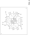
- Figure 1 shows an unmanned aerial vehicle 100 lifting a load 200.
- the load 200 depicted in Figure 1 is contained within a flexible bag, but an unmanned aerial vehicle 100 according to the present invention may be used for any type of load.
- the unmanned aerial vehicle 100 comprises a frame 2.
- the frame 2 may comprise a housing or form a part thereof.
- the frame 2 depicted in the Figures is generally cross shaped when viewed from above, but any suitable shape may be used.
- the frame 2 comprises a plurality of feet 2 for supporting the unmanned aerial vehicle 100 on the ground.
- the unmanned aerial vehicle 100 further comprises a flight system 4 and a load system 6. Each of the flight system 4 and the load system 6 are coupled to the frame 2.
- a cargo area is provided on the unmanned aerial vehicle.
- the cargo area may, for example, be a container such as a cargo bay for receiving a load.
- the cargo area may be inside the frame/housing 2.
- the cargo area may comprise a connection point 8 to which a load can be coupled.
- the connection point 8 may be provided on an outer surface of the frame/housing 2.
- the unmanned aerial vehicle 100 is provided with a connection point 8 provided on the frame 2. The connection point 8 allows a load 200 to be attached to the unmanned aerial vehicle 100.
- the flight system 4 provides the thrust required to fly and manoeuvre the unmanned aerial vehicle 100 in an unloaded state.
- the flight system 4 comprises one or more rotor assembly 40, preferably three or more.
- Each rotor assembly 40 comprises a flight rotor 42 and a corresponding electric motor 44.
- the flight rotor 42 is attached to and driven by the electric motor 44.
- the electric motor 44 is attached to the frame 2.
- One or more sources of electrical power (not shown) are provided to drive the electric motors 44 and hence drive the rotors 42 to fly the unmanned aerial vehicle 100.
- the sources of electrical power may be batteries, such as lithium-ion batteries.
- an even number of rotor assemblies 40 are provided.
- the unmanned aerial vehicle 100 comprises three, four, six or eight rotor assemblies 40. These rotor assemblies 40 are preferably provided around an outer periphery of the unmanned aerial vehicle 100 as shown in Figure 2 .
- an outer perimeter of the unmanned aerial vehicle 100 is defined by the rotor assemblies 40.
- the rotor assemblies 40 are preferably provided symmetrically around the unmanned aerial vehicle 100 to provide balanced forces in flight.
- the rotor assemblies 40 define a thrust direction 46 in which air is directed to produce thrust for flight.
- a plane X may be defined passing through each one of the rotor assemblies 40. This plane X is generally perpendicular to the ground plane when the unmanned aerial vehicle is sat on level ground for take-off.
- the thrust direction 46 of each rotor assembly 40 is generally vertically downwards (e.g. with respect to the unmanned aerial vehicle 100 when the feet are sat on level ground) or generally perpendicular to the plane X.
- the thrust direction 46 of each rotor assembly may have a deviation of up to and including 20 degrees from the perpendicular to the plane X. Preferably the deviation is between 10 and 20 degrees. While the thrust direction 46 of each rotor assembly 40 may deviate by up to 20 degrees, the net thrust direction of all the rotor assemblies 40 is preferably substantially perpendicular to the plane X.
- a controller 10 is provided on the unmanned aerial vehicle 100 for controlling the flight system 4 to fly and manoeuvre the unmanned aerial vehicle 100. While the controller 10 may be a single unit, it also may be a plurality of distributed units each of which contribute to the overall controller 10.
- the unmanned aerial vehicle 100 further comprises a load system 6.
- This load system 6 is used to provide additional thrust in order to lift a load 200.
- the load system 6 is preferably powered by combustion and so preferably comprises a combustion chamber.
- the load system 6 preferably comprises one or more gas turbine propulsion systems 62.
- a gas turbine propulsion system 62 is a system for generating thrust which is driven by expanding hot gasses produced, for example, by burning a fuel.
- gas turbine propulsion systems 62 may comprise a ducted fan which produces the additional thrust by way of exhausting a jet of gas.
- the gas turbine propulsion system 62 may be a turbojet, turbofan or turboprop.
- gas turbine propulsion systems 62 When a plurality of gas turbine propulsion systems 62 are provided, these are preferably arranged with an N-fold rotational symmetry in a plane generally perpendicular to the thrust direction 46, where N is the number of gas turbine propulsion systems 62.
- the plane generally perpendicular to the thrust direction 46 may be the plane X.
- Figure 2 shoes two gas turbine propulsion systems 62 and as shown in Figure 2 these gas turbine propulsion systems 62 are arranged in a 2-fold rotational symmetry.
- One or more fuel storage tanks 64 are provided on the unmanned aerial vehicle 100 and are connected to the gas turbine propulsion systems 62.
- Each fuel storage tank 64 stores combustible fuel (such as avtur (jet fuel)) for powering the gas turbine propulsion systems 62.
- the fuel has a greater specific energy than the batteries of the flight system 4. Jet fuel for example has a specific energy on the order of 42 MJ/kg. Therefore, the thrust to weight ratio provided by these gas turbine propulsion systems 62 is much greater than the rotor assemblies 40.
- gas turbine propulsion systems 62 cannot provide the fast and agile attitude control needed to fly the unmanned aerial vehicle 100 as the thrusts can only be varied by altering the fuel flow rate.
- the rotor assembly 40 because it is electric, can vary its thrust much quicker by sending a different electrical signal to the electric motor.
- Each gas turbine propulsion system 62 may be provided within a radius defined by the rotor assemblies 40.
- the radius may be defined by the innermost or outermost points of each rotor assembly 40.
- the fuel storage tanks 84 and cargo area are also provided within this radius.
- the cargo area is most preferably provided in a centre of the unmanned aerial vehicle 100.
- each gas turbine propulsion system 62 does not overlap with the rotors 42. This ensures that the air displaced by the rotors 42 does not subsequently contact any gas turbine propulsion systems 62.
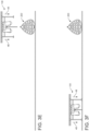
- Figure 3A shows the unmanned aerial vehicle 100 at a first location with a load 200 to be moved at a spaced-apart second location.
- the unmanned aerial vehicle 100 carries out a take-off procedure in a first mode of operation as shown in Figure 3B .
- the rotor assemblies 40 are actuated in order to generate a thrust 48 to allow the unmanned aerial vehicle 100 to take-off the ground and manoeuvre towards the load 200.
- the lift thrusts generated by the respective propulsion systems of the unmanned aerial vehicle 100 are depicted by arrows in the direction of the expelled air.
- the direction of the force generated on the unmanned aerial vehicle 100 by this expelled air will be opposite to the direction of the arrows.
- the unmanned aerial vehicle 100 is generally positioned above the load 200 as depicted in Figure 3C .
- the tether 82 is connected to the load 200 via any conventional mechanism.
- the gas turbine propulsion systems 62 are activated by the controller 10 to generate an additional lift 68 for lifting the load 200.
- the controller 10 may comprise first and second control systems. The first control system controls the flight system 4 and the second control system controls the load system 6.
- This additional thrust 68 acts to counteract the weight L applied by the load 200 onto the unmanned aerial vehicle 100.
- the rotor assemblies 40 can continue to fly and manoeuvre the vehicle 100 as their contribution is not required to lift the load 200.
- Figure 3D shows the unmanned aerial vehicle 100 beginning to lift the load 200 from the ground.
- the load 200 can then be transported to a further location as shown in Figure 3E and detached from the tether 82 via any conventional means. Once the load 200 has been detached from the unmanned aerial vehicle 100 the turbine propulsion system 62 may be deactivated.
- the rotor assemblies 40 may fly the unmanned aerial vehicle 100 back to a base position as shown in Figure 3F .
- the present invention allows an unmanned aerial vehicle 100 to be used to lift and transport heavy loads while still maintaining the manoeuvrability of a conventional unmanned aerial vehicle.
- the unmanned aerial vehicle comprises a load sensor (for example, as part of the connection point 8) in communication with the controller 10.
- the load sensor is configured to provide a signal indicative of the weight applied by the load 200 attached to the connection point 8.
- the controller is then configured to control the load system 6 and hence the gas turbine propulsion system 62 in response to the signal indicative of the weight L applied to the connection point 82.
- the controller 10 may be used in a closed-loop control system to balance the weight L applied to connection point 8 with the force provided by the thrust of the gas turbine propulsion systems 62.
- the second control system may vary the throttle of the gas turbine propulsion systems 62 based on the sensed load to balance the load and thrust.
- the gas turbine propulsion systems 62 may be angled with respect to the thrust direction of the flight rotors 42. This angling of the gas turbine propulsion systems 62 may be symmetrical so as to ensure that each gas turbine propulsion system 62 is arranged to counteract one another and hence not to contribute to movement in the horizontal direction. That is, the net thrust vector is substantially only in the vertical direction, perpendicular to the plane X. This can be used to enhance the stability of the unmanned aerial vehicle 100.
- the gas turbine propulsion systems 62 may each be angled by up to 20 degrees from the perpendicular to the plane X (that is, they may diverge from the vertical direction by up to 20 degrees). Preferably the angle may be between 10 and 20 degrees. This directs the jet plume(s) away from the load 200.
- the tether 82 of the present invention allows the unmanned aerial vehicle 100 to fly around the load 200 before the weight L of the load 200 is applied to the connection point 8. In particular, this is useful for instances where the unmanned aerial vehicle 100 may be attached to load 200 prior to take-off or may be detached after landing. In such embodiments the unmanned aerial vehicle 100 is able to take-off and/or land without the weight L of the load 200 being applied to the connection point 8 thanks to a slack in the tether 82. As this weight L is not being applied to the connection point 6 this unmanned aerial vehicle 100 may land and/or take-off using only the rotor assemblies 40 which, as discussed above, are much easier for fine control.
- the tether 82 may be releaseably attached to the unmanned aerial vehicle 100 to allow quick collection, lifting and depositing of a load 200.
- the tether may be remotely releasable from the unmanned aerial vehicle 100. This may be in the form of any known mechanism but in preferred embodiments may be via an electromagnet which can be selectively magnetised to attach and detach the tether 82.
Landscapes
- Engineering & Computer Science (AREA)
- Aviation & Aerospace Engineering (AREA)
- Chemical & Material Sciences (AREA)
- Combustion & Propulsion (AREA)
- Mechanical Engineering (AREA)
- Remote Sensing (AREA)
- Control Of Position, Course, Altitude, Or Attitude Of Moving Bodies (AREA)
- Toys (AREA)
- Electric Propulsion And Braking For Vehicles (AREA)
Claims (15)
- Unbemanntes Luftfahrzeug (100), umfassend:ein Flugsystem (4) zum Erzeugen von Schub, um das unbemannte Luftfahrzeug (100) zu manövrieren, umfassend:einen oder mehrere Flugrotoren (42), welche eine Ebene (X), welche durch jeden Flugrotor (42) verläuft, und eine Schubrichtung (46) definieren, welche im Wesentlichen senkrecht zu der Ebene (X) liegt; undeinen oder mehrere Elektromotoren (44) zum Antreiben des einen oder der mehreren Flugrotoren (42);einen Frachtbereich zum Koppeln mit oder zum Aufnehmen einer Last (200);ein Lastsystem (6) zum Bereitstellen von Schub zusätzlich zu dem Schub, welcher von dem Flugsystem (4) bereitgestellt wird, um damit eine Last (200) anzuheben, welche an einem Verbindungspunkt angebracht und mit dem Frachtbereich gekoppelt oder darin aufgenommen ist, wobei das Lastsystem (6) umfasst:
ein erstes Gasturbinen-Antriebssystem (62);eine Steuereinheit (10), welche dazu eingerichtet ist, das Flugsystem (4) und das Lastsystem (6) zu steuern; undeinen Lastsensor in Kommunikation mit der Steuereinheit (10), wobei der Lastsensor dazu eingerichtet ist, ein Signal bereitzustellen, welches ein Gewicht anzeigt, welches durch die Last (200) ausgeübt wird, welche an dem Verbindungspunkt angebracht ist,wobei die Steuereinheit (10) dazu eingerichtet ist, das Lastsystem (6) in Reaktion auf das Signal zu steuern. - Unbemanntes Luftfahrzeug (100) nach Anspruch 1, wobei das Lastsystem (6) eine Mehrzahl von Gasturbinen-Antriebssystemen (62) umfasst, wobei die Gasturbinen-Antriebssysteme (62) vorzugsweise mit einer N-fachen Rotationssymmetrie in der Ebene (X) der Flugrotoren (42) um ein Zentrum des unbemannten Luftfahrzeugs (100) angeordnet sind, wobei N die Anzahl der Gasturbinen-Antriebssysteme (62) ist.
- Unbemanntes Luftfahrzeug (100) nach Anspruch 2, wobei jedes Gas-Antriebssystem bei einem Winkel bezüglich der Schubrichtung (46) der Flugrotoren (42) bereitgestellt ist.
- Unbemanntes Luftfahrzeug (100) nach einem vorhergehenden Anspruch, wobei das oder jedes Gasturbinen-Antriebssystem (62) einen Mantelpropeller umfasst, um den zusätzlichen Schub in der Form seines Abgasstrahls zu erzeugen, wobei das Gasturbinen-Antriebssystem (62) vorzugsweise umfasst: einen Turbojet; Turbofan oder Turboprop.
- Unbemanntes Luftfahrzeug (100) nach einem vorhergehenden Anspruch, wobei das Flugsystem (4) zwei oder mehr Flugrotoren (42) umfasst, welche an einem Außenumfang des unbemannten Luftfahrzeugs (100) angeordnet sind, wobei das Flugsystem (4) vorzugsweise vier oder acht Flugrotoren (42) umfasst.
- Unbemanntes Luftfahrzeug (100) nach Anspruch 5, wobei jedes Gasturbinen-Antriebssystem (62) innerhalb eines Radus bereitgestellt ist, welcher durch die Flugrotoren (42) definiert ist.
- Unbemanntes Luftfahrzeug (100) nach einem vorhergehenden Anspruch, wobei die Steuereinheit (10) umfasst:ein erstes Steuersystem, welches dazu eingerichtet ist, das Flugsystem (4) zu steuern; undein zweites Steuersystem, welches dazu eingerichtet ist, das Lastsystem (6) zu steuern, wobei:
das erste und zweite Steuersystem voneinander unabhängig sind. - Unbemanntes Luftfahrzeug (100) nach einem vorhergehenden Anspruch, wobei die Steuereinheit (10) dazu eingerichtet ist, das Lastsystem (6) in einer Closed-Loop-Steuerung zu steuern, um die Kraft, welche von dem Lastsystem (6) bereitgestellt wird, und das Gewicht auszugleichen, welches auf den Verbindungspunkt ausgeübt wird.
- Unbemanntes Luftfahrzeug (100) nach einem vorhergehenden Anspruch, wobei das Fahrzeug einen ersten Betriebsmodus aufweist, in welchem das Flugsystem (4) dazu betrieben wird, das unbemannte Luftfahrzeug (100) zu starten und/oder zu landen, und in welchem das Lastsystem (6) inaktiv ist, wobei das Fahrzeug vorzugsweise einen zweiten Betriebsmodus aufweist, in welchem das Lastsystem (6) aktiviert ist, um Schub bereitzustellen, welcher gleich dem Gewicht der Last (200) ist, und in welchem das Flugsystem (4) verwendet wird, um Schub zu erzeugen, um das unbemannte Luftfahrzeug (100) und die Last (200) zu manövrieren.
- Unbemanntes Luftfahrzeug (100) nach einem vorhergehenden Anspruch, wobei der Frachtbereich an einer Mitte des unbemannten Luftfahrzeugs (100) bereitgestellt ist.
- Unbemanntes Luftfahrzeug (100) nach einem vorhergehenden Anspruch, wobei der Frachtbereich einen Verbindungspunkt (8) und einen Haltegurt (82) umfasst.
- Unbemanntes Luftfahrzeug (100) nach Anspruch 11, wobei der Haltegurt (82) lösbar an dem unbemannten Luftfahrzeug (100) und/oder der Last (200) angebracht ist.
- Unbemanntes Luftfahrzeug (100) nach Anspruch 11 oder 12, wobei der Haltegurt (82) entfernt lösbar ist, vorzugsweise mittels eines Elektromagneten.
- Verfahren zum Betreiben eines unbemannten Luftfahrzeugs (100), umfassend die Schritte:Bereitstellen eines unbemannten Luftfahrzeugs (100) nach einem vorhergehenden Anspruch;Starten des Fahrzeugs vom Untergrund unter Verwendung lediglich des Flugsystems (4);Anbringen einer Last (200) an einem Verbindungspunkt; undAktivieren des Lastsystems (6), um zusätzlichen Schub bereitzustellen, um die Last (200) anzuheben.
- Verfahren nach Anspruch 14, wobei:der Lastbereich den Verbindungspunkt (8) und einen Haltegurt (82) umfasst;der Schritt des Koppelns oder Aufnehmens der Last (200) vor dem Schritt des Startens ausgeführt wird; unddie Last (200) an dem Haltegurt (82) derart angebracht wird, dass das unbemannte Luftfahrzeug (100) um die Last (200) unter Durchhang des Haltegurts (82) herumfliegen kann, bevor das Gewicht der Last (200) auf den Verbindungspunkt (8) eingewirkt wird.
Priority Applications (1)
| Application Number | Priority Date | Filing Date | Title |
|---|---|---|---|
| EP24193323.3A EP4434897A3 (de) | 2019-12-06 | 2019-12-06 | Unbemanntes luftfahrzeug |
Applications Claiming Priority (1)
| Application Number | Priority Date | Filing Date | Title |
|---|---|---|---|
| PCT/GB2019/053451 WO2021111097A1 (en) | 2019-12-06 | 2019-12-06 | An unmanned aerial vehicle |
Related Child Applications (2)
| Application Number | Title | Priority Date | Filing Date |
|---|---|---|---|
| EP24193323.3A Division-Into EP4434897A3 (de) | 2019-12-06 | 2019-12-06 | Unbemanntes luftfahrzeug |
| EP24193323.3A Division EP4434897A3 (de) | 2019-12-06 | 2019-12-06 | Unbemanntes luftfahrzeug |
Publications (3)
| Publication Number | Publication Date |
|---|---|
| EP4069586A1 EP4069586A1 (de) | 2022-10-12 |
| EP4069586B1 true EP4069586B1 (de) | 2024-09-11 |
| EP4069586C0 EP4069586C0 (de) | 2024-09-11 |
Family
ID=69723975
Family Applications (2)
| Application Number | Title | Priority Date | Filing Date |
|---|---|---|---|
| EP19856473.4A Active EP4069586B1 (de) | 2019-12-06 | 2019-12-06 | Unbemanntes luftfahrzeug |
| EP24193323.3A Pending EP4434897A3 (de) | 2019-12-06 | 2019-12-06 | Unbemanntes luftfahrzeug |
Family Applications After (1)
| Application Number | Title | Priority Date | Filing Date |
|---|---|---|---|
| EP24193323.3A Pending EP4434897A3 (de) | 2019-12-06 | 2019-12-06 | Unbemanntes luftfahrzeug |
Country Status (3)
| Country | Link |
|---|---|
| US (1) | US20230011791A1 (de) |
| EP (2) | EP4069586B1 (de) |
| WO (1) | WO2021111097A1 (de) |
Families Citing this family (2)
| Publication number | Priority date | Publication date | Assignee | Title |
|---|---|---|---|---|
| CA3193570A1 (en) * | 2020-09-27 | 2022-04-28 | Tomas A. Pribanic | Low noise vertical take-off and landing (vtol) unmanned air vehicle (uav) |
| US12168510B2 (en) * | 2023-02-07 | 2024-12-17 | Hunter William KOWALD | Compact personal flight vehicle |
Family Cites Families (17)
| Publication number | Priority date | Publication date | Assignee | Title |
|---|---|---|---|---|
| US3888435A (en) * | 1974-07-18 | 1975-06-10 | Kenneth R Foote | Helicopter with auxiliary load-supporting and lifting capacity |
| WO2006069291A2 (en) * | 2004-12-22 | 2006-06-29 | Aurora Flight Sciences Corporation | System and method for utilizing stored electrical energy for vtol aircraft thrust enhancement and attitude control |
| WO2011023834A1 (es) * | 2009-08-26 | 2011-03-03 | Munoz Saiz Manuel | Sistema sustentador propulsor y estabilizador para aeronaves de despegue y aterrizaje vertical |
| US9073624B2 (en) * | 2013-12-09 | 2015-07-07 | The Boeing Company | Methods and apparatus to cooperatively lift a payload |
| US11485488B1 (en) * | 2014-12-07 | 2022-11-01 | L3Harris Latitude Llc | Vertical take-off and landing aircraft with rotor thrust yaw control |
| US10676193B2 (en) * | 2015-04-17 | 2020-06-09 | Sikorsky Aircraft Corporation | External load management functions for vertical take-off and landing aircraft |
| US9828094B2 (en) * | 2015-07-26 | 2017-11-28 | John B. McMillion | Autonomous cleaning system |
| US10071804B1 (en) * | 2015-09-28 | 2018-09-11 | Amazon Technologies, Inc. | Delivery drop rate modulation |
| JP6393888B2 (ja) * | 2015-11-06 | 2018-09-26 | 株式会社プロドローン | 運搬装置 |
| US10625853B2 (en) * | 2016-07-01 | 2020-04-21 | Textron Innovations Inc. | Automated configuration of mission specific aircraft |
| EP3978363B1 (de) * | 2016-10-13 | 2024-05-08 | Alexander Poltorak | Vorrichtung und verfahren zum ausbalancieren eines flugzeugs mit robotischen armen |
| EP3529155A4 (de) * | 2016-10-24 | 2020-06-17 | Hybridskys Technology Pty Ltd | Hybridflugzeug |
| CN108622404B (zh) * | 2017-03-17 | 2022-05-24 | 株式会社理光 | 飞行器以及飞行系统 |
| US20180362169A1 (en) * | 2017-06-16 | 2018-12-20 | Xing Du | Aircraft with electric and fuel engines |
| US20200031458A1 (en) * | 2018-07-25 | 2020-01-30 | Mark E Strauss | Unmanned Aerial Vehicle with Thrust Decoupling, Active Wing Loading, Omnidirectional Lift Control and/or Vibration Management |
| US11851178B2 (en) * | 2020-02-14 | 2023-12-26 | The Aerospace Corporation | Long range endurance aero platform system |
| US12084174B2 (en) * | 2021-08-04 | 2024-09-10 | Conrad Ryan | Multi-axis hybrid aircraft |
-
2019
- 2019-12-06 EP EP19856473.4A patent/EP4069586B1/de active Active
- 2019-12-06 WO PCT/GB2019/053451 patent/WO2021111097A1/en not_active Ceased
- 2019-12-06 EP EP24193323.3A patent/EP4434897A3/de active Pending
- 2019-12-06 US US17/782,777 patent/US20230011791A1/en active Pending
Also Published As
| Publication number | Publication date |
|---|---|
| EP4434897A2 (de) | 2024-09-25 |
| WO2021111097A1 (en) | 2021-06-10 |
| EP4069586A1 (de) | 2022-10-12 |
| EP4069586C0 (de) | 2024-09-11 |
| US20230011791A1 (en) | 2023-01-12 |
| EP4434897A3 (de) | 2024-11-13 |
Similar Documents
| Publication | Publication Date | Title |
|---|---|---|
| US12110092B2 (en) | Drone systems and methods | |
| CN109606673B (zh) | 具有可互换的有效载荷模块的倾转旋翼式飞行器 | |
| US10994841B2 (en) | Electric JetPack device | |
| JP4499155B2 (ja) | 回転翼輸送手段 | |
| CN112041257B (zh) | 搬运风力涡轮机部件以便组装它们的系统和方法 | |
| US9440736B2 (en) | Special personal electric helicopter device with integral wind turbine recharging capability | |
| US9555884B2 (en) | Method for improving ground travel capability and enhancing stealth in unmanned aerial vehicles | |
| US11679879B2 (en) | Vehicle system | |
| US20150136897A1 (en) | Aircraft, preferably unmanned | |
| CN101746507A (zh) | 用于函道风扇式无人空中系统的混合动力 | |
| CN107207088A (zh) | 可重新配置的无人飞行器系统 | |
| EP3083398A1 (de) | Modulares elektrisches senkrechtstarterflugzeug | |
| EP3645871B1 (de) | System und verfahren zur handhabung von windturbinenkomponenten zur montage davon | |
| US11091265B1 (en) | Auto rotating canister | |
| EP4069586B1 (de) | Unbemanntes luftfahrzeug | |
| WO2019001665A1 (en) | SYSTEM AND METHOD FOR HANDLING WIND ELEMENTS | |
| GB2578083A (en) | An unmanned aerial vehicle | |
| WO2024253690A1 (en) | Jet powered aircraft | |
| WO2022263881A1 (en) | An unmanned aerial vehicle | |
| KR20250117001A (ko) | 비행모드에 따른 형태변경이 가능한 수직이착륙기 | |
| KR20180111408A (ko) | 회전익과 고정익을 구비한 수직 이착륙 비행체 |
Legal Events
| Date | Code | Title | Description |
|---|---|---|---|
| STAA | Information on the status of an ep patent application or granted ep patent |
Free format text: STATUS: UNKNOWN |
|
| STAA | Information on the status of an ep patent application or granted ep patent |
Free format text: STATUS: THE INTERNATIONAL PUBLICATION HAS BEEN MADE |
|
| PUAI | Public reference made under article 153(3) epc to a published international application that has entered the european phase |
Free format text: ORIGINAL CODE: 0009012 |
|
| STAA | Information on the status of an ep patent application or granted ep patent |
Free format text: STATUS: REQUEST FOR EXAMINATION WAS MADE |
|
| 17P | Request for examination filed |
Effective date: 20220530 |
|
| AK | Designated contracting states |
Kind code of ref document: A1 Designated state(s): AL AT BE BG CH CY CZ DE DK EE ES FI FR GB GR HR HU IE IS IT LI LT LU LV MC MK MT NL NO PL PT RO RS SE SI SK SM TR |
|
| DAV | Request for validation of the european patent (deleted) | ||
| DAX | Request for extension of the european patent (deleted) | ||
| RIC1 | Information provided on ipc code assigned before grant |
Ipc: B64U 101/60 20230101ALI20240213BHEP Ipc: B64U 50/19 20230101ALI20240213BHEP Ipc: B64U 50/12 20230101ALI20240213BHEP Ipc: B64U 10/13 20230101ALI20240213BHEP Ipc: B64C 29/00 20060101ALI20240213BHEP Ipc: B64D 1/22 20060101AFI20240213BHEP |
|
| GRAP | Despatch of communication of intention to grant a patent |
Free format text: ORIGINAL CODE: EPIDOSNIGR1 |
|
| STAA | Information on the status of an ep patent application or granted ep patent |
Free format text: STATUS: GRANT OF PATENT IS INTENDED |
|
| INTG | Intention to grant announced |
Effective date: 20240404 |
|
| GRAS | Grant fee paid |
Free format text: ORIGINAL CODE: EPIDOSNIGR3 |
|
| GRAA | (expected) grant |
Free format text: ORIGINAL CODE: 0009210 |
|
| STAA | Information on the status of an ep patent application or granted ep patent |
Free format text: STATUS: THE PATENT HAS BEEN GRANTED |
|
| AK | Designated contracting states |
Kind code of ref document: B1 Designated state(s): AL AT BE BG CH CY CZ DE DK EE ES FI FR GB GR HR HU IE IS IT LI LT LU LV MC MK MT NL NO PL PT RO RS SE SI SK SM TR |
|
| REG | Reference to a national code |
Ref country code: GB Ref legal event code: FG4D |
|
| REG | Reference to a national code |
Ref country code: CH Ref legal event code: EP |
|
| REG | Reference to a national code |
Ref country code: DE Ref legal event code: R096 Ref document number: 602019058865 Country of ref document: DE |
|
| REG | Reference to a national code |
Ref country code: IE Ref legal event code: FG4D |
|
| U01 | Request for unitary effect filed |
Effective date: 20240912 |
|
| U07 | Unitary effect registered |
Designated state(s): AT BE BG DE DK EE FI FR IT LT LU LV MT NL PT RO SE SI Effective date: 20241004 |
|
| PG25 | Lapsed in a contracting state [announced via postgrant information from national office to epo] |
Ref country code: NO Free format text: LAPSE BECAUSE OF FAILURE TO SUBMIT A TRANSLATION OF THE DESCRIPTION OR TO PAY THE FEE WITHIN THE PRESCRIBED TIME-LIMIT Effective date: 20241211 |
|
| PG25 | Lapsed in a contracting state [announced via postgrant information from national office to epo] |
Ref country code: GR Free format text: LAPSE BECAUSE OF FAILURE TO SUBMIT A TRANSLATION OF THE DESCRIPTION OR TO PAY THE FEE WITHIN THE PRESCRIBED TIME-LIMIT Effective date: 20241212 |
|
| U20 | Renewal fee for the european patent with unitary effect paid |
Year of fee payment: 6 Effective date: 20241213 |
|
| PG25 | Lapsed in a contracting state [announced via postgrant information from national office to epo] |
Ref country code: HR Free format text: LAPSE BECAUSE OF FAILURE TO SUBMIT A TRANSLATION OF THE DESCRIPTION OR TO PAY THE FEE WITHIN THE PRESCRIBED TIME-LIMIT Effective date: 20240911 |
|
| PG25 | Lapsed in a contracting state [announced via postgrant information from national office to epo] |
Ref country code: RS Free format text: LAPSE BECAUSE OF FAILURE TO SUBMIT A TRANSLATION OF THE DESCRIPTION OR TO PAY THE FEE WITHIN THE PRESCRIBED TIME-LIMIT Effective date: 20241211 Ref country code: ES Free format text: LAPSE BECAUSE OF FAILURE TO SUBMIT A TRANSLATION OF THE DESCRIPTION OR TO PAY THE FEE WITHIN THE PRESCRIBED TIME-LIMIT Effective date: 20240911 |
|
| PG25 | Lapsed in a contracting state [announced via postgrant information from national office to epo] |
Ref country code: RS Free format text: LAPSE BECAUSE OF FAILURE TO SUBMIT A TRANSLATION OF THE DESCRIPTION OR TO PAY THE FEE WITHIN THE PRESCRIBED TIME-LIMIT Effective date: 20241211 Ref country code: NO Free format text: LAPSE BECAUSE OF FAILURE TO SUBMIT A TRANSLATION OF THE DESCRIPTION OR TO PAY THE FEE WITHIN THE PRESCRIBED TIME-LIMIT Effective date: 20241211 Ref country code: HR Free format text: LAPSE BECAUSE OF FAILURE TO SUBMIT A TRANSLATION OF THE DESCRIPTION OR TO PAY THE FEE WITHIN THE PRESCRIBED TIME-LIMIT Effective date: 20240911 Ref country code: GR Free format text: LAPSE BECAUSE OF FAILURE TO SUBMIT A TRANSLATION OF THE DESCRIPTION OR TO PAY THE FEE WITHIN THE PRESCRIBED TIME-LIMIT Effective date: 20241212 Ref country code: ES Free format text: LAPSE BECAUSE OF FAILURE TO SUBMIT A TRANSLATION OF THE DESCRIPTION OR TO PAY THE FEE WITHIN THE PRESCRIBED TIME-LIMIT Effective date: 20240911 |
|
| PG25 | Lapsed in a contracting state [announced via postgrant information from national office to epo] |
Ref country code: IS Free format text: LAPSE BECAUSE OF FAILURE TO SUBMIT A TRANSLATION OF THE DESCRIPTION OR TO PAY THE FEE WITHIN THE PRESCRIBED TIME-LIMIT Effective date: 20250111 |
|
| PG25 | Lapsed in a contracting state [announced via postgrant information from national office to epo] |
Ref country code: SM Free format text: LAPSE BECAUSE OF FAILURE TO SUBMIT A TRANSLATION OF THE DESCRIPTION OR TO PAY THE FEE WITHIN THE PRESCRIBED TIME-LIMIT Effective date: 20240911 |
|
| PG25 | Lapsed in a contracting state [announced via postgrant information from national office to epo] |
Ref country code: CZ Free format text: LAPSE BECAUSE OF FAILURE TO SUBMIT A TRANSLATION OF THE DESCRIPTION OR TO PAY THE FEE WITHIN THE PRESCRIBED TIME-LIMIT Effective date: 20240911 Ref country code: PL Free format text: LAPSE BECAUSE OF FAILURE TO SUBMIT A TRANSLATION OF THE DESCRIPTION OR TO PAY THE FEE WITHIN THE PRESCRIBED TIME-LIMIT Effective date: 20240911 |
|
| PG25 | Lapsed in a contracting state [announced via postgrant information from national office to epo] |
Ref country code: SK Free format text: LAPSE BECAUSE OF FAILURE TO SUBMIT A TRANSLATION OF THE DESCRIPTION OR TO PAY THE FEE WITHIN THE PRESCRIBED TIME-LIMIT Effective date: 20240911 |
|
| PG25 | Lapsed in a contracting state [announced via postgrant information from national office to epo] |
Ref country code: MC Free format text: LAPSE BECAUSE OF FAILURE TO SUBMIT A TRANSLATION OF THE DESCRIPTION OR TO PAY THE FEE WITHIN THE PRESCRIBED TIME-LIMIT Effective date: 20240911 |
|
| PLBE | No opposition filed within time limit |
Free format text: ORIGINAL CODE: 0009261 |
|
| STAA | Information on the status of an ep patent application or granted ep patent |
Free format text: STATUS: NO OPPOSITION FILED WITHIN TIME LIMIT |
|
| REG | Reference to a national code |
Ref country code: CH Ref legal event code: PL |
|
| 26N | No opposition filed |
Effective date: 20250612 |
|
| GBPC | Gb: european patent ceased through non-payment of renewal fee |
Effective date: 20241211 |
|
| PG25 | Lapsed in a contracting state [announced via postgrant information from national office to epo] |
Ref country code: GB Free format text: LAPSE BECAUSE OF NON-PAYMENT OF DUE FEES Effective date: 20241211 |
|
| PG25 | Lapsed in a contracting state [announced via postgrant information from national office to epo] |
Ref country code: CH Free format text: LAPSE BECAUSE OF NON-PAYMENT OF DUE FEES Effective date: 20241231 |
|
| PG25 | Lapsed in a contracting state [announced via postgrant information from national office to epo] |
Ref country code: IE Free format text: LAPSE BECAUSE OF NON-PAYMENT OF DUE FEES Effective date: 20241206 |