EP4069563B1 - Spring brake actuator - Google Patents
Spring brake actuator Download PDFInfo
- Publication number
- EP4069563B1 EP4069563B1 EP19817641.4A EP19817641A EP4069563B1 EP 4069563 B1 EP4069563 B1 EP 4069563B1 EP 19817641 A EP19817641 A EP 19817641A EP 4069563 B1 EP4069563 B1 EP 4069563B1
- Authority
- EP
- European Patent Office
- Prior art keywords
- spring brake
- clamping means
- brake actuator
- spring
- basic body
- Prior art date
- Legal status (The legal status is an assumption and is not a legal conclusion. Google has not performed a legal analysis and makes no representation as to the accuracy of the status listed.)
- Active
Links
Images


Classifications
-
- B—PERFORMING OPERATIONS; TRANSPORTING
- B60—VEHICLES IN GENERAL
- B60T—VEHICLE BRAKE CONTROL SYSTEMS OR PARTS THEREOF; BRAKE CONTROL SYSTEMS OR PARTS THEREOF, IN GENERAL; ARRANGEMENT OF BRAKING ELEMENTS ON VEHICLES IN GENERAL; PORTABLE DEVICES FOR PREVENTING UNWANTED MOVEMENT OF VEHICLES; VEHICLE MODIFICATIONS TO FACILITATE COOLING OF BRAKES
- B60T17/00—Component parts, details, or accessories of power brake systems not covered by groups B60T8/00, B60T13/00 or B60T15/00, or presenting other characteristic features
- B60T17/08—Brake cylinders other than ultimate actuators
- B60T17/085—Spring loaded brake actuators
- B60T17/086—Spring loaded brake actuators with emergency release device
-
- B—PERFORMING OPERATIONS; TRANSPORTING
- B60—VEHICLES IN GENERAL
- B60T—VEHICLE BRAKE CONTROL SYSTEMS OR PARTS THEREOF; BRAKE CONTROL SYSTEMS OR PARTS THEREOF, IN GENERAL; ARRANGEMENT OF BRAKING ELEMENTS ON VEHICLES IN GENERAL; PORTABLE DEVICES FOR PREVENTING UNWANTED MOVEMENT OF VEHICLES; VEHICLE MODIFICATIONS TO FACILITATE COOLING OF BRAKES
- B60T15/00—Construction arrangement, or operation of valves incorporated in power brake systems and not covered by groups B60T11/00 or B60T13/00
- B60T15/02—Application and release valves
-
- B—PERFORMING OPERATIONS; TRANSPORTING
- B60—VEHICLES IN GENERAL
- B60T—VEHICLE BRAKE CONTROL SYSTEMS OR PARTS THEREOF; BRAKE CONTROL SYSTEMS OR PARTS THEREOF, IN GENERAL; ARRANGEMENT OF BRAKING ELEMENTS ON VEHICLES IN GENERAL; PORTABLE DEVICES FOR PREVENTING UNWANTED MOVEMENT OF VEHICLES; VEHICLE MODIFICATIONS TO FACILITATE COOLING OF BRAKES
- B60T17/00—Component parts, details, or accessories of power brake systems not covered by groups B60T8/00, B60T13/00 or B60T15/00, or presenting other characteristic features
- B60T17/08—Brake cylinders other than ultimate actuators
- B60T17/083—Combination of service brake actuators with spring loaded brake actuators
-
- F—MECHANICAL ENGINEERING; LIGHTING; HEATING; WEAPONS; BLASTING
- F16—ENGINEERING ELEMENTS AND UNITS; GENERAL MEASURES FOR PRODUCING AND MAINTAINING EFFECTIVE FUNCTIONING OF MACHINES OR INSTALLATIONS; THERMAL INSULATION IN GENERAL
- F16D—COUPLINGS FOR TRANSMITTING ROTATION; CLUTCHES; BRAKES
- F16D2121/00—Type of actuator operation force
- F16D2121/02—Fluid pressure
- F16D2121/08—Fluid pressure acting on a membrane-type actuator, e.g. for gas pressure
- F16D2121/10—Fluid pressure acting on a membrane-type actuator, e.g. for gas pressure for releasing a normally applied brake
-
- F—MECHANICAL ENGINEERING; LIGHTING; HEATING; WEAPONS; BLASTING
- F16—ENGINEERING ELEMENTS AND UNITS; GENERAL MEASURES FOR PRODUCING AND MAINTAINING EFFECTIVE FUNCTIONING OF MACHINES OR INSTALLATIONS; THERMAL INSULATION IN GENERAL
- F16D—COUPLINGS FOR TRANSMITTING ROTATION; CLUTCHES; BRAKES
- F16D2127/00—Auxiliary mechanisms
Definitions
- EP 0 897 845 A2 and US 5, 226,291 A also discloses spring brake actuators with a diaphragm retainer.
- the clamping means extend diagonally outwards from the basic body in an angle of 1° - 60° relative to the longitudinal axis, preferably 25° - 40°.
- the retaining device may be clamped securely into an accommodation space. This helps to ensure that the valve is kept in place during operation.
- the retaining device may be easily assembled and dissembled while the clamping means help to center the retaining device in the accommodation space.
- the retaining device is fitted to the spring guide by at least one of the following: press fit, snap fit, threaded fastening, adhesive bonding, shrink fitting and wobbles riveting.
- the clamping means are arranged at the basic body and along a circumference of the basic body, wherein the clamping means are spaced apart from each other forming slits between the clamping means to allow for a circulation of air through the slits.
- the retaining device takes advantage of the same benefits and preferred embodiments as the spring brake actuator comprising such a retaining device according to the invention. In this regard, reference is made to the above explanations and their content is included herein.
- Fig. 1 shows a cross-sectional schematic view of a spring brake actuator 2.
- the spring brake actuator 2 comprises a cylinder housing 4. Inside the cylinder housing 4, a compression spring 8 and a pressure chamber 23 are arranged.
- the compression spring 8 rests on the left side of Fig. 1 against a cylinder housing base 6 and on the opposite side on a spring guide 12 of a spring brake piston 10.
- the spring brake piston 10 is in Fig. 1 held in a brake release position by a positive pressure inside the pressure chamber 23.
- the spring brake piston 10 is adapted to act upon a diaphragm 24 of the spring brake actuator 2 which transmits the inflicted force to a rod 26 which, in turn, transmits the applied power to the wheel brakes (not shown).
- the spring brake actuator 2 furthermore comprises a release bolt 29.
- the release bolt 29 is utilized to release the spring brake actuator 2 in case of malfunctions, for example.
- the spring brake actuator 2 moreover comprises a flange 18 which is utilized to connect a service brake 27 to the spring brake actuator 2.
- the service brake 27 comprises a service brake pressure chamber 25 into which a pressure may be built up to generate a force upon the service diaphragm 28 which transmits the inflicted force to the rod 26.
- Fig. 2 shows a detailed view of a part of the spring brake actuator 2 comprising the retaining device 16.
- the retaining device 16 retains the check valve 14 and attaches it to the spring guide 12.
- the retaining device 16 holds the check valve 14 in place and also allows for a passage of air through the retaining device 16.
- the retaining device 16 is attached in a receiving space 30 and held in position with the help of a receiving space shoulder 32.
- Fig. 3 shows a detailed perspective of the retaining device 16.
- the retaining device 16 comprises a basic body 34 and clamping means 36.
- the clamping means 36 are arranged along a circumference 38 of the basic body 34.
- the clamping means 36 are spaced apart from each other forming slits 40 in between the clamping means 36 to allow for a circulation of air through the slits 40.
- the slits have a width w s .
- a first side 44 of the basic body 34 is shown.
- a longitudinal axis 42 of the retaining device 16 is illustrated.
- the basic body 34 comprises eight clamping means 36.
- the retaining device 16 comprises a circular groove 50 being arranged circumferentially around the longitudinal axis 42. The groove 50 facilitates the capability of the clamping means 36 to be bendable inwardly towards the longitudinal axis 42 to allow for an easy assembly of the retaining device 16.
- Fig. 4 shows the retaining device 16 from another side showing a second side 46 of the basic body 34. It can be seen from Fig. 4 that the clamping means 36 comprise a circular shoulder 48. This circular shoulder 48 may be brought into alignment with the receiving space shoulder 32 (see Fig. 2 ) to center and accommodate the retaining device 16 in the desired position.
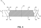
- Fig. 5 shows a cross-sectional view of the retaining device 16 comprising the basic body 34 and clamping means 36.
- the retaining device 16 comprises the circular groove 50 being arranged circumferentially around the longitudinal axis 42 of the basic body 34.
- the circular groove 50 is V-shaped 52.
- the circular groove 50 is arranged at the first side 44 of the basic body 34, only.
- the basic body 34 has a thickness t b while the clamping means 36 extend diagonally outwards from the basic body 34 in an angle 54.
Landscapes
- Engineering & Computer Science (AREA)
- Transportation (AREA)
- Mechanical Engineering (AREA)
- Braking Arrangements (AREA)
- Braking Systems And Boosters (AREA)
Description
- The present invention relates to a spring brake actuator, in particular a parking or emergency spring brake actuator for use in a commercial vehicle, said actuator comprising a cylinder housing comprising a cylinder housing base, a spring brake piston located in said cylinder housing for applying a braking force, a spring guide being attached to the spring brake piston and a compression spring located between the cylinder housing base and the spring guide of the spring brake piston, said compression spring being effective to push the spring brake piston away from the base, wherein the spring guide comprises a valve and a retaining device for retaining the valve, the retaining device comprising a basic body and clamping means for clamping the device to the spring guide.
- Spring brake actuators of the aforementioned kind are used in the commercial vehicle industry to provide a parking and/or emergency brake capability. Spring brake actuators are regularly connected to a service brake actuator and often act upon the same brake components which transmit the brake force to the vehicle wheel. Utilizing these two brake types together leads to the challenge of ensuring that only one of the brakes is activated at a time. This is because whenever one of the brakes, such as the parking brake, is activated, adding additional brake force by the second brake, such as the service brake, potentially causes damage to the brake components. Activating the two brakes together is also called compounding.
- To reduce brake forces in case of compounding, overpressure valves are used in modern brake systems. In spring brake actuators, for example, overpressure check valves are utilized which are regularly arranged in the spring guide of the spring brake piston.
- To retain such valves to the spring guide, a combination of a circlip and a plate is utilized in the prior art. Circlip and plate help to retain the valve and also to ensure that air may pass through the retaining components and reach the valve.
Beschreibung Seite 2 und 2a (Reinschrift) - There are, however, certain drawbacks associated with this solution. First of all, it has been found that the assembly of the two parts is rather difficult and time-consuming as these parts need to be assembled in the correct order, correct orientation and they need to be centered within an accommodation space of the spring guide. Furthermore, the airflow through the circlip/plate combination has found to be uneven and a turbulent airflow may be generated, which is generally unwanted.
-
US 6,148,711 A describes such a fluid operated spring brake actuator with a retaining device as mentioned above. The spring brake actuator has also a normally closed one-way check valve, extends through the pressure plate and the diaphragm for a temporary fluid communication. -
EP 0 897 845 A2 andUS 5, 226,291 A also discloses spring brake actuators with a diaphragm retainer. - Consequently, it has been an object of the invention to provide a spring brake actuator of the aforementioned type having a retaining device which is easier and faster to assemble and which improves the airflow characteristics through the device.
- The invention attains this object by providing a retaining device according to claim 1. In particular, the invention attains this object in an embodiment where the clamping means are arranged at the basic body and along a circumference of the basic body and wherein the clamping means are spaced apart from each other forming slits between the clamping means to allow for a circulation of air through the slits.
- The invention is based on the finding that by combining the basic body and the clamping means into one component, the likelihood of erroneous assemblies can be reduced significantly. Furthermore, the design allows for a self-centering capability of the retaining device in the accommodation space of the spring guide. Additionally, the slits allow for an increased and even airflow through the retaining device towards the valve. Based on the number, geometry, and width of the slits between the clamping means, the airflow characteristics may be influenced individually depending on the valve type and the assembly conditions.
- In a preferred embodiment, the basic body has a shape of a disc. With the help of this, the retaining surface of the retaining device is increased while the basic body at the same time provides enough stability to securely retain the valve.
- According to yet another alternative embodiment, the retaining device comprises a circular groove being arranged circumferentially around a longitudinal axis of the basic body. This has been found to be beneficial to facilitate the clamping functionality of the clamping means as the groove provides room into which the clamping means may be bended when the retaining device is assembled into the accommodation space of the spring guide.
- In a preferred embodiment, the circular groove is V-shaped. This has been found to be beneficial to maintain the stability of the retaining device while at the same time providing enough room for the clamping means to bend to the inside when the retaining device is assembled.
- Preferably, the retaining device has a first side and a second side, the second side being arranged axially opposite of the first side, wherein the circular groove is arranged at the first side, only. This ensures that at the second side, which is preferably used to retain the valve, the retaining surface is maximized. On the other hand, on the first side, which is preferably the air inlet side of the retaining device, enough room is provided for the clamping means to bend inwardly when assembled without closing the slits between the clamping means.
- In a preferred embodiment, the clamping means extend diagonally outwards from the basic body in an angle of 1° - 60° relative to the longitudinal axis, preferably 25° - 40°. By designing the clamping means in a way that they extend diagonally outwards from the basic body, the retaining device may be clamped securely into an accommodation space. This helps to ensure that the valve is kept in place during operation. Furthermore, the retaining device may be easily assembled and dissembled while the clamping means help to center the retaining device in the accommodation space.
- In yet another preferred embodiment, the clamping means are integrally formed with the basic body. In other words, it is preferred that the clamping means and the basic body are manufactured as one piece. This not only reduces manufacturing costs but also ensures a lower part-complexity.
- Furthermore, it is preferred that the basic body comprises 5-20 clamping means, preferably 8 clamping means. This number of clamping means has been found to be beneficial to ensure that the retaining device may be securely fixed in an accommodation space, center itself and provide a reasonable airflow through the device while the complexity of the device is kept low.
- In a preferred embodiment, the slits between the spaced apart clamping means have a width of 0,3 - 2 mm, preferably 0.7 mm. This dimensioning of the slits has been found to facilitate a sufficient and mostly unturbulent airflow through the valve. Furthermore, the slits support the bending capabilities of the clamping means facilitating the assembly of the retaining device in the accommodation space.
- In yet another preferred embodiment the basic body has a thickness tb of 0,5 mm - 2 mm, preferably 1 mm. This keeps the dimensions of the retaining device low and ensures that it may be utilized in accommodation spaces at which the room available for the accommodation of the retaining device is limited.
- Furthermore, it is preferred that the clamping means comprise a circular shoulder for positioning the retaining device in a spring guide. Such a circular shoulder ensures that the retaining device may be properly secured to an accommodation space which also preferably has a correspondent shoulder. This helps to ensure that the valve is safely retained with respect to the spring guide.
- In yet another preferred embodiment, the retaining device is partially or completely made of plastic material, sheet metal, or a combination of the above. Preferably, the plastic material is a crystalline or semi crystalline plastic material, particularly preferred polypropylene terephtalate (PPT), polyamide (PA), polyoxymethylene (POM), polyphthalamide (PPA), or polypropylene (PP). It is furthermore preferred that the sheet metal is steel, a steel alloy, aluminum or an aluminum alloy. This selection of materials has been found to be beneficial for the proposed application of the retaining device.
- According to a preferred embodiment, the retaining device is fitted to the spring guide by at least one of the following: press fit, snap fit, threaded fastening, adhesive bonding, shrink fitting and wobbles riveting. These different ways of fitting the retaining device to the spring guide have been found to be beneficial for various applications of the retaining device at vehicle brakes.
- According to a further aspect not part of the present invention, it is provided a retaining device for retaining a valve, the retaining device comprising a basic body and clamping means for clamping the device to a spring guide.
- According to this further aspect, the clamping means are arranged at the basic body and along a circumference of the basic body, wherein the clamping means are spaced apart from each other forming slits between the clamping means to allow for a circulation of air through the slits. The retaining device takes advantage of the same benefits and preferred embodiments as the spring brake actuator comprising such a retaining device according to the invention. In this regard, reference is made to the above explanations and their content is included herein.
- This invention will now be described with reference to the accompanying drawings which illustrate, by way of example and not by way of limitation, one of several possible embodiments of the clutch servo proposed herein, and wherein:
- Fig. 1:
- shows a preferred embodiment of a spring brake actuator according to the concept of the invention in a sectional view;
- Fig. 2:
- shows a detail of the spring brake actuator according to
Fig. 1 showing a retaining device according to the concept of the invention; - Figs. 3 and 4:
- show a preferred embodiment of the retaining device according to the concept of the invention in perspective views; and
- Fig. 5:
- shows a sectional view of the retaining device according to the concept of the invention.
-
Fig. 1 shows a cross-sectional schematic view of aspring brake actuator 2. Thespring brake actuator 2 comprises a cylinder housing 4. Inside the cylinder housing 4, acompression spring 8 and apressure chamber 23 are arranged. Thecompression spring 8 rests on the left side ofFig. 1 against acylinder housing base 6 and on the opposite side on aspring guide 12 of a spring brake piston 10. The spring brake piston 10 is inFig. 1 held in a brake release position by a positive pressure inside thepressure chamber 23. - The spring brake piston 10 is adapted to act upon a
diaphragm 24 of thespring brake actuator 2 which transmits the inflicted force to arod 26 which, in turn, transmits the applied power to the wheel brakes (not shown). - The
spring brake actuator 2 furthermore comprises arelease bolt 29. Therelease bolt 29 is utilized to release thespring brake actuator 2 in case of malfunctions, for example. Thespring brake actuator 2 moreover comprises aflange 18 which is utilized to connect aservice brake 27 to thespring brake actuator 2. Theservice brake 27 comprises a servicebrake pressure chamber 25 into which a pressure may be built up to generate a force upon theservice diaphragm 28 which transmits the inflicted force to therod 26. - In case both the
spring brake actuator 2 and theservice brake 27 are operated simultaneously, pressure is released from the servicebrake pressure chamber 25 through aninternal breathing valve 20 and via atubular stem 22 through a retainingdevice 16 and acheck valve 14 into thepressure chamber 23. With the help of this, it is avoided that whenever thespring brake actuator 2 and theservice brake 27 are operated simultaneously (which is also called compounding), the braking forces of the two brakes add up and damage therod 26 or parts of the wheel brakes. -
Fig. 2 shows a detailed view of a part of thespring brake actuator 2 comprising the retainingdevice 16. As can be seen fromFig. 2 , the retainingdevice 16 retains thecheck valve 14 and attaches it to thespring guide 12. The retainingdevice 16 holds thecheck valve 14 in place and also allows for a passage of air through the retainingdevice 16. The retainingdevice 16 is attached in a receivingspace 30 and held in position with the help of a receivingspace shoulder 32. -
Fig. 3 shows a detailed perspective of the retainingdevice 16. The retainingdevice 16 comprises abasic body 34 and clamping means 36. The clamping means 36 are arranged along acircumference 38 of thebasic body 34. The clamping means 36 are spaced apart from each other formingslits 40 in between the clamping means 36 to allow for a circulation of air through theslits 40. The slits have a width ws. InFig. 3 , afirst side 44 of thebasic body 34 is shown. Furthermore, alongitudinal axis 42 of the retainingdevice 16 is illustrated. Thebasic body 34 comprises eight clamping means 36. Also, the retainingdevice 16 comprises acircular groove 50 being arranged circumferentially around thelongitudinal axis 42. Thegroove 50 facilitates the capability of the clamping means 36 to be bendable inwardly towards thelongitudinal axis 42 to allow for an easy assembly of the retainingdevice 16. -
Fig. 4 shows the retainingdevice 16 from another side showing asecond side 46 of thebasic body 34. It can be seen fromFig. 4 that the clamping means 36 comprise acircular shoulder 48. Thiscircular shoulder 48 may be brought into alignment with the receiving space shoulder 32 (seeFig. 2 ) to center and accommodate the retainingdevice 16 in the desired position. -
Fig. 5 shows a cross-sectional view of the retainingdevice 16 comprising thebasic body 34 and clamping means 36. The retainingdevice 16 comprises thecircular groove 50 being arranged circumferentially around thelongitudinal axis 42 of thebasic body 34. Thecircular groove 50 is V-shaped 52. Furthermore, thecircular groove 50 is arranged at thefirst side 44 of thebasic body 34, only. Thebasic body 34 has a thickness tb while the clamping means 36 extend diagonally outwards from thebasic body 34 in anangle 54. -
- 2
- spring brake actuator
- 4
- cylinder housing
- 6
- cylinder housing base
- 8
- compression spring
- 10
- spring brake piston
- 12
- spring guide
- 14
- check valve
- 16
- retaining device
- 18
- flange
- 20
- internal breathing valve
- 22
- tubular stem
- 23
- pressure chamber
- 24
- diaphragm
- 25
- service brake pressure chamber
- 26
- rod
- 27
- service brake
- 28
- service diaphragm
- 29
- release bolt
- 30
- receiving space
- 32
- receiving space shoulder
- 34
- basic body
- 36
- clamping means
- 38
- circumference of the basic body
- 40
- slits
- 42
- longitudinal axis
- 44
- first side of basic body
- 46
- second side of basic body
- 48
- circular shoulder
- 50
- circular groove
- 52
- V-shape
- 54
- clamping means extending angle
- ws
- width of slits
- tb
- thickness of basic body
Claims (12)
- A spring brake actuator (2), in particular a parking or emergency spring brake actuator (2) for use in a commercial vehicle, said actuator (2) comprising:- a cylinder housing (4) comprising a cylinder housing base (6),- a spring brake piston (10) located in said cylinder housing (4) for applying a braking force,- a spring guide (12) being attached to the spring brake piston (10),- a compression spring (8) located between the cylinder housing base (6) and the spring guide (12) of the spring brake piston (10), said compression spring (8) being effective to push the spring brake piston (10) away from the base (6), wherein the spring guide (12) comprises a valve (14) and a retaining device (16) for retaining the valve (14), the retaining device (16) comprising a basic body (34) and clamping means (36) for clamping the device (16) to the spring guide (12),characterized in that the clamping means (36) are arranged at the basic body (34) and along a circumference (38) of the basic body (34),wherein the clamping means (36) are spaced apart from each other forming slits (40) between the clamping means (36) to allow for a circulation of air through the slits (40).
- The spring brake actuator (2) according to claim 1,
characterized in that the basic body (34) has the shape of a disc. - The spring brake actuator (2) according to claim 1 or 2,
characterized in that the retaining device (16) comprises a circular groove (50) being arranged circumferentially around a longitudinal axis (42) of the basic body (34). - The spring brake actuator (2) according to claim 3,
characterized in that the circular groove (50) is V-shaped (52). - The spring brake actuator (2) according to claim 3 or 4,
characterized in that the retaining device (16) has a first side (44) and a second side (46), the second side (46) being arranged axially opposite of the first side (44), wherein the circular groove (50) is arranged at the first side (44), only. - The spring brake actuator (2) according to any of the preceding claims, characterized in that the clamping means (36) extend diagonally outwards from the basic body (34) in an angle (54) of 1° - 60° relative to the longitudinal axis (42), preferably 25-40°.
- The spring brake actuator (2) according to any of the preceding claims, characterized in that the clamping means (36) are integrally formed with the basic body (34).
- The spring brake actuator (2) according to any of the preceding claims, characterized in that the basic body (34) comprises 5-20 clamping means (36), preferably 8 clamping means (36).
- The spring brake actuator (2) according to any of the preceding claims, characterized in that the slits (40) between the spaced apart clamping means (36) have a width (ws) of 0,3 - 2 mm, preferably 0,7 mm.
- The spring brake actuator (2) according to any of the preceding claims, characterized in that the basic body has a thickness (tb) of 0,5 mm - 2 mm, preferably 1 mm.
- The spring brake actuator (2) according to any of the preceding claims, characterized in that the clamping means (36) comprise a circular shoulder (48) for positioning the retaining device (16) in the spring guide (12).
- The spring brake actuator (2) according to any of the preceding claims, characterized in that the retaining device (16) is partially or completely made of sheet metal, preferably steel or aluminum sheet metal, and/or plastic, preferably crystalline or semi crystalline plastic, particularly preferred polypropylene terephtalate (PPT), polyamide (PA), polyoxymethylene (POM), polyphthalamide (PPA), or polypropylene (PP), or a combination of the above.
Applications Claiming Priority (1)
| Application Number | Priority Date | Filing Date | Title |
|---|---|---|---|
| PCT/EP2019/083868 WO2021110272A1 (en) | 2019-12-05 | 2019-12-05 | Spring brake actuator and retaining device for such spring brake actuator |
Publications (2)
| Publication Number | Publication Date |
|---|---|
| EP4069563A1 EP4069563A1 (en) | 2022-10-12 |
| EP4069563B1 true EP4069563B1 (en) | 2024-07-10 |
Family
ID=68841086
Family Applications (1)
| Application Number | Title | Priority Date | Filing Date |
|---|---|---|---|
| EP19817641.4A Active EP4069563B1 (en) | 2019-12-05 | 2019-12-05 | Spring brake actuator |
Country Status (3)
| Country | Link |
|---|---|
| US (1) | US12559082B2 (en) |
| EP (1) | EP4069563B1 (en) |
| WO (1) | WO2021110272A1 (en) |
Families Citing this family (3)
| Publication number | Priority date | Publication date | Assignee | Title |
|---|---|---|---|---|
| DE102023119814A1 (en) * | 2023-07-26 | 2025-01-30 | Knorr-Bremse Systeme für Nutzfahrzeuge GmbH | Air-operated spring brake cylinder with central breathing device |
| EP4650234A1 (en) | 2024-05-14 | 2025-11-19 | ZF CV Systems Europe BV | Diaphragm arrangement for a spring brake actuator of a pneumatic braking system of a vehicle, in particular utility vehicle, spring brake actuator, pneumatic braking system, and vehicle |
| EP4660031A1 (en) * | 2024-06-06 | 2025-12-10 | ZF CV Systems Europe BV | Divider arrangement for a spring brake actuator for a pneumatic braking system for a vehicle, in particular utility vehicle |
Family Cites Families (24)
| Publication number | Priority date | Publication date | Assignee | Title |
|---|---|---|---|---|
| US2503854A (en) * | 1947-05-15 | 1950-04-11 | Disto Corp | Snap action clamping device |
| US2630343A (en) * | 1950-04-26 | 1953-03-03 | Garlock Packing Co | Sealing device |
| US3037522A (en) * | 1958-04-04 | 1962-06-05 | Otto Items Inc | Check valve construction |
| US3331390A (en) * | 1964-07-06 | 1967-07-18 | Norgren Co C A | Check valve |
| US3954121A (en) * | 1975-03-17 | 1976-05-04 | The Weatherhead Company | Vent check valve |
| US4820409A (en) * | 1988-04-19 | 1989-04-11 | Facet Enterprises, Inc. | Plastic pressure relief valve assembly |
| EP0542568A3 (en) * | 1991-11-15 | 1993-08-04 | Bendix Limited | Spring force actuators |
| US5226291A (en) | 1991-12-17 | 1993-07-13 | General Motors Corporation | Vacuum booster diaphragm/support plate retention method |
| US6164187A (en) * | 1997-08-15 | 2000-12-26 | Holland Neway International, Inc. | Diaphragm retainer for spring brake actuator |
| AU1625499A (en) * | 1997-12-05 | 1999-06-28 | Holland Neway International, Inc. | Normally-closed diaphragm check valve |
| AU2000278521A1 (en) * | 2000-03-15 | 2001-09-24 | Holland Neway International, Inc. | Sealed brake actuator |
| US6907818B2 (en) * | 2003-10-29 | 2005-06-21 | Haldex Brake Corporation | System and method for providing dry filtered air to a brake actuator |
| US8657299B2 (en) * | 2004-07-15 | 2014-02-25 | John E. Rode | Mounting rings for shafts |
| US7461907B2 (en) * | 2005-07-18 | 2008-12-09 | Bendix Spicer Foundation Brake Llc | Rod/seal bearing arrangement utilizing locking fingers |
| US20070034465A1 (en) * | 2005-08-12 | 2007-02-15 | Larry Thompson | Flexible bushing assembly for spring brake push rod center seal |
| US20080178884A1 (en) * | 2007-01-25 | 2008-07-31 | Gerson Ronald L | Fluid Valve with Center Post |
| US9016319B2 (en) * | 2007-08-22 | 2015-04-28 | Societe Bic | Relief valves for fuel cell systems |
| US9409267B2 (en) * | 2010-06-17 | 2016-08-09 | Bendix Spicer Foundation Brake Llc | Snap-in center seal bushing |
| US8978839B2 (en) * | 2012-05-07 | 2015-03-17 | Haldex Brake Products Corporation | Pneumatic brake actuator with flow insensitive two way control valve |
| DE102012107331A1 (en) * | 2012-08-09 | 2014-02-13 | Franz Haimer Maschinenbau Kg | Balancing or measuring device |
| US9487203B2 (en) * | 2013-04-10 | 2016-11-08 | G&P Automotive Co., Ltd. | Brake actuator |
| JP6330730B2 (en) * | 2015-05-29 | 2018-05-30 | 株式会社アドヴィックス | Negative pressure booster |
| DE102017119822B4 (en) * | 2017-08-29 | 2024-02-01 | Zeroclamp Gmbh | Dual function of a centering cone for holding a clamping device and clamping device |
| US10663025B2 (en) * | 2018-07-31 | 2020-05-26 | Bendix Spicer Foundation Brake Llc | Bushing assembly for a spring brake actuator of a vehicle air braking system |
-
2019
- 2019-12-05 US US17/781,456 patent/US12559082B2/en active Active
- 2019-12-05 EP EP19817641.4A patent/EP4069563B1/en active Active
- 2019-12-05 WO PCT/EP2019/083868 patent/WO2021110272A1/en not_active Ceased
Also Published As
| Publication number | Publication date |
|---|---|
| US12559082B2 (en) | 2026-02-24 |
| WO2021110272A1 (en) | 2021-06-10 |
| US20230001911A1 (en) | 2023-01-05 |
| EP4069563A1 (en) | 2022-10-12 |
Similar Documents
| Publication | Publication Date | Title |
|---|---|---|
| EP4069563B1 (en) | Spring brake actuator | |
| EP2760720B1 (en) | Parking brake piston for a parking brake chamber | |
| US9062766B2 (en) | Locking apparatus | |
| US10864897B2 (en) | Brake device for a hydraulic motor vehicle brake system | |
| CN113544027B (en) | Spring brake actuator for a vehicle, in particular a parking or emergency brake actuator for a commercial vehicle | |
| MX2014003604A (en) | Parking piston direct connection to apr rod. | |
| US20130240773A1 (en) | Valve of a piston pump with a closing body | |
| US20190249731A1 (en) | Abutment clip for disk brakes | |
| JP2018520010A (en) | Axle caulking tool | |
| US10626939B2 (en) | Adhesive attachment of the disc brake pushrod plate to the diaphragm | |
| US7390174B2 (en) | Piston pump | |
| CN102686464A (en) | Valve module, in particular solenoid valve for a brake system of a motor vehicle, method for the production of said type of valve module | |
| US7451689B2 (en) | Combined service brake and spring brake cylinder assembly | |
| EP2639126B1 (en) | Dust or stone shield for the pushrod of a brake actuator | |
| US7555902B2 (en) | Tandem master cylinder with central valves | |
| EP4023512B1 (en) | Stamped spring seat for use in spring brake actuator, and spring brake actuator for use in commercial vehicles | |
| EP3840993B1 (en) | Pneumatic brake control module components | |
| EP4650235A1 (en) | Spring brake actuator for a pneumatic braking system of a vehicle, in particular utility vehicle, pneumatic braking system, vehicle and method | |
| US12090972B2 (en) | Spring brake actuator | |
| WO2007092481A2 (en) | Brake assembly, brake actuator and method of making a brake actuator | |
| US7287457B1 (en) | Structure for retaining a piston assembly in position relative to a cylinder | |
| CN113784879A (en) | Piston tube assemblies for spring brake actuators and spring brake actuators | |
| US20160377133A1 (en) | Brake disk device for a vehicle | |
| EP4059792B1 (en) | Spring brake actuator for use in a vehicle, and use of a disc spring therein | |
| WO2025080480A1 (en) | Eccentrically mounted guide pin for air disc brake system and methods for the use and assembly thereof |
Legal Events
| Date | Code | Title | Description |
|---|---|---|---|
| STAA | Information on the status of an ep patent application or granted ep patent |
Free format text: STATUS: UNKNOWN |
|
| STAA | Information on the status of an ep patent application or granted ep patent |
Free format text: STATUS: THE INTERNATIONAL PUBLICATION HAS BEEN MADE |
|
| PUAI | Public reference made under article 153(3) epc to a published international application that has entered the european phase |
Free format text: ORIGINAL CODE: 0009012 |
|
| STAA | Information on the status of an ep patent application or granted ep patent |
Free format text: STATUS: REQUEST FOR EXAMINATION WAS MADE |
|
| 17P | Request for examination filed |
Effective date: 20220705 |
|
| AK | Designated contracting states |
Kind code of ref document: A1 Designated state(s): AL AT BE BG CH CY CZ DE DK EE ES FI FR GB GR HR HU IE IS IT LI LT LU LV MC MK MT NL NO PL PT RO RS SE SI SK SM TR |
|
| DAV | Request for validation of the european patent (deleted) | ||
| DAX | Request for extension of the european patent (deleted) | ||
| GRAP | Despatch of communication of intention to grant a patent |
Free format text: ORIGINAL CODE: EPIDOSNIGR1 |
|
| STAA | Information on the status of an ep patent application or granted ep patent |
Free format text: STATUS: GRANT OF PATENT IS INTENDED |
|
| INTG | Intention to grant announced |
Effective date: 20240314 |
|
| GRAS | Grant fee paid |
Free format text: ORIGINAL CODE: EPIDOSNIGR3 |
|
| GRAA | (expected) grant |
Free format text: ORIGINAL CODE: 0009210 |
|
| STAA | Information on the status of an ep patent application or granted ep patent |
Free format text: STATUS: THE PATENT HAS BEEN GRANTED |
|
| AK | Designated contracting states |
Kind code of ref document: B1 Designated state(s): AL AT BE BG CH CY CZ DE DK EE ES FI FR GB GR HR HU IE IS IT LI LT LU LV MC MK MT NL NO PL PT RO RS SE SI SK SM TR |
|
| REG | Reference to a national code |
Ref country code: CH Ref legal event code: EP |
|
| REG | Reference to a national code |
Ref country code: DE Ref legal event code: R096 Ref document number: 602019055069 Country of ref document: DE |
|
| REG | Reference to a national code |
Ref country code: LT Ref legal event code: MG9D |
|
| REG | Reference to a national code |
Ref country code: NL Ref legal event code: MP Effective date: 20240710 |
|
| PG25 | Lapsed in a contracting state [announced via postgrant information from national office to epo] |
Ref country code: PT Free format text: LAPSE BECAUSE OF FAILURE TO SUBMIT A TRANSLATION OF THE DESCRIPTION OR TO PAY THE FEE WITHIN THE PRESCRIBED TIME-LIMIT Effective date: 20241111 |
|
| REG | Reference to a national code |
Ref country code: AT Ref legal event code: MK05 Ref document number: 1701806 Country of ref document: AT Kind code of ref document: T Effective date: 20240710 |
|
| PG25 | Lapsed in a contracting state [announced via postgrant information from national office to epo] |
Ref country code: NL Free format text: LAPSE BECAUSE OF FAILURE TO SUBMIT A TRANSLATION OF THE DESCRIPTION OR TO PAY THE FEE WITHIN THE PRESCRIBED TIME-LIMIT Effective date: 20240710 |
|
| PG25 | Lapsed in a contracting state [announced via postgrant information from national office to epo] |
Ref country code: PT Free format text: LAPSE BECAUSE OF FAILURE TO SUBMIT A TRANSLATION OF THE DESCRIPTION OR TO PAY THE FEE WITHIN THE PRESCRIBED TIME-LIMIT Effective date: 20241111 Ref country code: NL Free format text: LAPSE BECAUSE OF FAILURE TO SUBMIT A TRANSLATION OF THE DESCRIPTION OR TO PAY THE FEE WITHIN THE PRESCRIBED TIME-LIMIT Effective date: 20240710 |
|
| PG25 | Lapsed in a contracting state [announced via postgrant information from national office to epo] |
Ref country code: NO Free format text: LAPSE BECAUSE OF FAILURE TO SUBMIT A TRANSLATION OF THE DESCRIPTION OR TO PAY THE FEE WITHIN THE PRESCRIBED TIME-LIMIT Effective date: 20241010 |
|
| PG25 | Lapsed in a contracting state [announced via postgrant information from national office to epo] |
Ref country code: GR Free format text: LAPSE BECAUSE OF FAILURE TO SUBMIT A TRANSLATION OF THE DESCRIPTION OR TO PAY THE FEE WITHIN THE PRESCRIBED TIME-LIMIT Effective date: 20241011 Ref country code: FI Free format text: LAPSE BECAUSE OF FAILURE TO SUBMIT A TRANSLATION OF THE DESCRIPTION OR TO PAY THE FEE WITHIN THE PRESCRIBED TIME-LIMIT Effective date: 20240710 Ref country code: PL Free format text: LAPSE BECAUSE OF FAILURE TO SUBMIT A TRANSLATION OF THE DESCRIPTION OR TO PAY THE FEE WITHIN THE PRESCRIBED TIME-LIMIT Effective date: 20240710 |
|
| PG25 | Lapsed in a contracting state [announced via postgrant information from national office to epo] |
Ref country code: BG Free format text: LAPSE BECAUSE OF FAILURE TO SUBMIT A TRANSLATION OF THE DESCRIPTION OR TO PAY THE FEE WITHIN THE PRESCRIBED TIME-LIMIT Effective date: 20240710 |
|
| PG25 | Lapsed in a contracting state [announced via postgrant information from national office to epo] |
Ref country code: LV Free format text: LAPSE BECAUSE OF FAILURE TO SUBMIT A TRANSLATION OF THE DESCRIPTION OR TO PAY THE FEE WITHIN THE PRESCRIBED TIME-LIMIT Effective date: 20240710 |
|
| PG25 | Lapsed in a contracting state [announced via postgrant information from national office to epo] |
Ref country code: IS Free format text: LAPSE BECAUSE OF FAILURE TO SUBMIT A TRANSLATION OF THE DESCRIPTION OR TO PAY THE FEE WITHIN THE PRESCRIBED TIME-LIMIT Effective date: 20241110 Ref country code: AT Free format text: LAPSE BECAUSE OF FAILURE TO SUBMIT A TRANSLATION OF THE DESCRIPTION OR TO PAY THE FEE WITHIN THE PRESCRIBED TIME-LIMIT Effective date: 20240710 |
|
| PG25 | Lapsed in a contracting state [announced via postgrant information from national office to epo] |
Ref country code: HR Free format text: LAPSE BECAUSE OF FAILURE TO SUBMIT A TRANSLATION OF THE DESCRIPTION OR TO PAY THE FEE WITHIN THE PRESCRIBED TIME-LIMIT Effective date: 20240710 |
|
| PG25 | Lapsed in a contracting state [announced via postgrant information from national office to epo] |
Ref country code: ES Free format text: LAPSE BECAUSE OF FAILURE TO SUBMIT A TRANSLATION OF THE DESCRIPTION OR TO PAY THE FEE WITHIN THE PRESCRIBED TIME-LIMIT Effective date: 20240710 Ref country code: RS Free format text: LAPSE BECAUSE OF FAILURE TO SUBMIT A TRANSLATION OF THE DESCRIPTION OR TO PAY THE FEE WITHIN THE PRESCRIBED TIME-LIMIT Effective date: 20241010 |
|
| PG25 | Lapsed in a contracting state [announced via postgrant information from national office to epo] |
Ref country code: RS Free format text: LAPSE BECAUSE OF FAILURE TO SUBMIT A TRANSLATION OF THE DESCRIPTION OR TO PAY THE FEE WITHIN THE PRESCRIBED TIME-LIMIT Effective date: 20241010 Ref country code: PL Free format text: LAPSE BECAUSE OF FAILURE TO SUBMIT A TRANSLATION OF THE DESCRIPTION OR TO PAY THE FEE WITHIN THE PRESCRIBED TIME-LIMIT Effective date: 20240710 Ref country code: NO Free format text: LAPSE BECAUSE OF FAILURE TO SUBMIT A TRANSLATION OF THE DESCRIPTION OR TO PAY THE FEE WITHIN THE PRESCRIBED TIME-LIMIT Effective date: 20241010 Ref country code: LV Free format text: LAPSE BECAUSE OF FAILURE TO SUBMIT A TRANSLATION OF THE DESCRIPTION OR TO PAY THE FEE WITHIN THE PRESCRIBED TIME-LIMIT Effective date: 20240710 Ref country code: IS Free format text: LAPSE BECAUSE OF FAILURE TO SUBMIT A TRANSLATION OF THE DESCRIPTION OR TO PAY THE FEE WITHIN THE PRESCRIBED TIME-LIMIT Effective date: 20241110 Ref country code: HR Free format text: LAPSE BECAUSE OF FAILURE TO SUBMIT A TRANSLATION OF THE DESCRIPTION OR TO PAY THE FEE WITHIN THE PRESCRIBED TIME-LIMIT Effective date: 20240710 Ref country code: GR Free format text: LAPSE BECAUSE OF FAILURE TO SUBMIT A TRANSLATION OF THE DESCRIPTION OR TO PAY THE FEE WITHIN THE PRESCRIBED TIME-LIMIT Effective date: 20241011 Ref country code: FI Free format text: LAPSE BECAUSE OF FAILURE TO SUBMIT A TRANSLATION OF THE DESCRIPTION OR TO PAY THE FEE WITHIN THE PRESCRIBED TIME-LIMIT Effective date: 20240710 Ref country code: ES Free format text: LAPSE BECAUSE OF FAILURE TO SUBMIT A TRANSLATION OF THE DESCRIPTION OR TO PAY THE FEE WITHIN THE PRESCRIBED TIME-LIMIT Effective date: 20240710 Ref country code: BG Free format text: LAPSE BECAUSE OF FAILURE TO SUBMIT A TRANSLATION OF THE DESCRIPTION OR TO PAY THE FEE WITHIN THE PRESCRIBED TIME-LIMIT Effective date: 20240710 Ref country code: AT Free format text: LAPSE BECAUSE OF FAILURE TO SUBMIT A TRANSLATION OF THE DESCRIPTION OR TO PAY THE FEE WITHIN THE PRESCRIBED TIME-LIMIT Effective date: 20240710 |
|
| REG | Reference to a national code |
Ref country code: DE Ref legal event code: R097 Ref document number: 602019055069 Country of ref document: DE |
|
| PG25 | Lapsed in a contracting state [announced via postgrant information from national office to epo] |
Ref country code: RO Free format text: LAPSE BECAUSE OF FAILURE TO SUBMIT A TRANSLATION OF THE DESCRIPTION OR TO PAY THE FEE WITHIN THE PRESCRIBED TIME-LIMIT Effective date: 20240710 Ref country code: DK Free format text: LAPSE BECAUSE OF FAILURE TO SUBMIT A TRANSLATION OF THE DESCRIPTION OR TO PAY THE FEE WITHIN THE PRESCRIBED TIME-LIMIT Effective date: 20240710 Ref country code: SM Free format text: LAPSE BECAUSE OF FAILURE TO SUBMIT A TRANSLATION OF THE DESCRIPTION OR TO PAY THE FEE WITHIN THE PRESCRIBED TIME-LIMIT Effective date: 20240710 |
|
| PG25 | Lapsed in a contracting state [announced via postgrant information from national office to epo] |
Ref country code: EE Free format text: LAPSE BECAUSE OF FAILURE TO SUBMIT A TRANSLATION OF THE DESCRIPTION OR TO PAY THE FEE WITHIN THE PRESCRIBED TIME-LIMIT Effective date: 20240710 |
|
| PG25 | Lapsed in a contracting state [announced via postgrant information from national office to epo] |
Ref country code: CZ Free format text: LAPSE BECAUSE OF FAILURE TO SUBMIT A TRANSLATION OF THE DESCRIPTION OR TO PAY THE FEE WITHIN THE PRESCRIBED TIME-LIMIT Effective date: 20240710 |
|
| PG25 | Lapsed in a contracting state [announced via postgrant information from national office to epo] |
Ref country code: SK Free format text: LAPSE BECAUSE OF FAILURE TO SUBMIT A TRANSLATION OF THE DESCRIPTION OR TO PAY THE FEE WITHIN THE PRESCRIBED TIME-LIMIT Effective date: 20240710 Ref country code: IT Free format text: LAPSE BECAUSE OF FAILURE TO SUBMIT A TRANSLATION OF THE DESCRIPTION OR TO PAY THE FEE WITHIN THE PRESCRIBED TIME-LIMIT Effective date: 20240710 |
|
| PLBE | No opposition filed within time limit |
Free format text: ORIGINAL CODE: 0009261 |
|
| STAA | Information on the status of an ep patent application or granted ep patent |
Free format text: STATUS: NO OPPOSITION FILED WITHIN TIME LIMIT |
|
| 26N | No opposition filed |
Effective date: 20250411 |
|
| PG25 | Lapsed in a contracting state [announced via postgrant information from national office to epo] |
Ref country code: MC Free format text: LAPSE BECAUSE OF FAILURE TO SUBMIT A TRANSLATION OF THE DESCRIPTION OR TO PAY THE FEE WITHIN THE PRESCRIBED TIME-LIMIT Effective date: 20240710 |
|
| REG | Reference to a national code |
Ref country code: CH Ref legal event code: PL |
|
| PG25 | Lapsed in a contracting state [announced via postgrant information from national office to epo] |
Ref country code: LU Free format text: LAPSE BECAUSE OF NON-PAYMENT OF DUE FEES Effective date: 20241205 |
|
| GBPC | Gb: european patent ceased through non-payment of renewal fee |
Effective date: 20241205 |
|
| PG25 | Lapsed in a contracting state [announced via postgrant information from national office to epo] |
Ref country code: SE Free format text: LAPSE BECAUSE OF FAILURE TO SUBMIT A TRANSLATION OF THE DESCRIPTION OR TO PAY THE FEE WITHIN THE PRESCRIBED TIME-LIMIT Effective date: 20240710 |
|
| REG | Reference to a national code |
Ref country code: BE Ref legal event code: MM Effective date: 20241231 |
|
| PG25 | Lapsed in a contracting state [announced via postgrant information from national office to epo] |
Ref country code: BE Free format text: LAPSE BECAUSE OF NON-PAYMENT OF DUE FEES Effective date: 20241231 Ref country code: GB Free format text: LAPSE BECAUSE OF NON-PAYMENT OF DUE FEES Effective date: 20241205 |
|
| PG25 | Lapsed in a contracting state [announced via postgrant information from national office to epo] |
Ref country code: FR Free format text: LAPSE BECAUSE OF NON-PAYMENT OF DUE FEES Effective date: 20241231 |
|
| PG25 | Lapsed in a contracting state [announced via postgrant information from national office to epo] |
Ref country code: CH Free format text: LAPSE BECAUSE OF NON-PAYMENT OF DUE FEES Effective date: 20241231 |
|
| PG25 | Lapsed in a contracting state [announced via postgrant information from national office to epo] |
Ref country code: IE Free format text: LAPSE BECAUSE OF NON-PAYMENT OF DUE FEES Effective date: 20241205 |
|
| PGFP | Annual fee paid to national office [announced via postgrant information from national office to epo] |
Ref country code: DE Payment date: 20250930 Year of fee payment: 7 |
|
| PG25 | Lapsed in a contracting state [announced via postgrant information from national office to epo] |
Ref country code: CY Free format text: LAPSE BECAUSE OF FAILURE TO SUBMIT A TRANSLATION OF THE DESCRIPTION OR TO PAY THE FEE WITHIN THE PRESCRIBED TIME-LIMIT; INVALID AB INITIO Effective date: 20191205 |