EP4069563B1 - Federspeicherbremszylinder - Google Patents
Federspeicherbremszylinder Download PDFInfo
- Publication number
- EP4069563B1 EP4069563B1 EP19817641.4A EP19817641A EP4069563B1 EP 4069563 B1 EP4069563 B1 EP 4069563B1 EP 19817641 A EP19817641 A EP 19817641A EP 4069563 B1 EP4069563 B1 EP 4069563B1
- Authority
- EP
- European Patent Office
- Prior art keywords
- spring brake
- clamping means
- brake actuator
- spring
- basic body
- Prior art date
- Legal status (The legal status is an assumption and is not a legal conclusion. Google has not performed a legal analysis and makes no representation as to the accuracy of the status listed.)
- Active
Links
Images


Classifications
-
- B—PERFORMING OPERATIONS; TRANSPORTING
- B60—VEHICLES IN GENERAL
- B60T—VEHICLE BRAKE CONTROL SYSTEMS OR PARTS THEREOF; BRAKE CONTROL SYSTEMS OR PARTS THEREOF, IN GENERAL; ARRANGEMENT OF BRAKING ELEMENTS ON VEHICLES IN GENERAL; PORTABLE DEVICES FOR PREVENTING UNWANTED MOVEMENT OF VEHICLES; VEHICLE MODIFICATIONS TO FACILITATE COOLING OF BRAKES
- B60T17/00—Component parts, details, or accessories of power brake systems not covered by groups B60T8/00, B60T13/00 or B60T15/00, or presenting other characteristic features
- B60T17/08—Brake cylinders other than ultimate actuators
- B60T17/085—Spring loaded brake actuators
- B60T17/086—Spring loaded brake actuators with emergency release device
-
- B—PERFORMING OPERATIONS; TRANSPORTING
- B60—VEHICLES IN GENERAL
- B60T—VEHICLE BRAKE CONTROL SYSTEMS OR PARTS THEREOF; BRAKE CONTROL SYSTEMS OR PARTS THEREOF, IN GENERAL; ARRANGEMENT OF BRAKING ELEMENTS ON VEHICLES IN GENERAL; PORTABLE DEVICES FOR PREVENTING UNWANTED MOVEMENT OF VEHICLES; VEHICLE MODIFICATIONS TO FACILITATE COOLING OF BRAKES
- B60T15/00—Construction arrangement, or operation of valves incorporated in power brake systems and not covered by groups B60T11/00 or B60T13/00
- B60T15/02—Application and release valves
-
- B—PERFORMING OPERATIONS; TRANSPORTING
- B60—VEHICLES IN GENERAL
- B60T—VEHICLE BRAKE CONTROL SYSTEMS OR PARTS THEREOF; BRAKE CONTROL SYSTEMS OR PARTS THEREOF, IN GENERAL; ARRANGEMENT OF BRAKING ELEMENTS ON VEHICLES IN GENERAL; PORTABLE DEVICES FOR PREVENTING UNWANTED MOVEMENT OF VEHICLES; VEHICLE MODIFICATIONS TO FACILITATE COOLING OF BRAKES
- B60T17/00—Component parts, details, or accessories of power brake systems not covered by groups B60T8/00, B60T13/00 or B60T15/00, or presenting other characteristic features
- B60T17/08—Brake cylinders other than ultimate actuators
- B60T17/083—Combination of service brake actuators with spring loaded brake actuators
-
- F—MECHANICAL ENGINEERING; LIGHTING; HEATING; WEAPONS; BLASTING
- F16—ENGINEERING ELEMENTS AND UNITS; GENERAL MEASURES FOR PRODUCING AND MAINTAINING EFFECTIVE FUNCTIONING OF MACHINES OR INSTALLATIONS; THERMAL INSULATION IN GENERAL
- F16D—COUPLINGS FOR TRANSMITTING ROTATION; CLUTCHES; BRAKES
- F16D2121/00—Type of actuator operation force
- F16D2121/02—Fluid pressure
- F16D2121/08—Fluid pressure acting on a membrane-type actuator, e.g. for gas pressure
- F16D2121/10—Fluid pressure acting on a membrane-type actuator, e.g. for gas pressure for releasing a normally applied brake
-
- F—MECHANICAL ENGINEERING; LIGHTING; HEATING; WEAPONS; BLASTING
- F16—ENGINEERING ELEMENTS AND UNITS; GENERAL MEASURES FOR PRODUCING AND MAINTAINING EFFECTIVE FUNCTIONING OF MACHINES OR INSTALLATIONS; THERMAL INSULATION IN GENERAL
- F16D—COUPLINGS FOR TRANSMITTING ROTATION; CLUTCHES; BRAKES
- F16D2127/00—Auxiliary mechanisms
Definitions
- EP 0 897 845 A2 and US 5, 226,291 A also discloses spring brake actuators with a diaphragm retainer.
- the clamping means extend diagonally outwards from the basic body in an angle of 1° - 60° relative to the longitudinal axis, preferably 25° - 40°.
- the retaining device may be clamped securely into an accommodation space. This helps to ensure that the valve is kept in place during operation.
- the retaining device may be easily assembled and dissembled while the clamping means help to center the retaining device in the accommodation space.
- the retaining device is fitted to the spring guide by at least one of the following: press fit, snap fit, threaded fastening, adhesive bonding, shrink fitting and wobbles riveting.
- the clamping means are arranged at the basic body and along a circumference of the basic body, wherein the clamping means are spaced apart from each other forming slits between the clamping means to allow for a circulation of air through the slits.
- the retaining device takes advantage of the same benefits and preferred embodiments as the spring brake actuator comprising such a retaining device according to the invention. In this regard, reference is made to the above explanations and their content is included herein.
- Fig. 1 shows a cross-sectional schematic view of a spring brake actuator 2.
- the spring brake actuator 2 comprises a cylinder housing 4. Inside the cylinder housing 4, a compression spring 8 and a pressure chamber 23 are arranged.
- the compression spring 8 rests on the left side of Fig. 1 against a cylinder housing base 6 and on the opposite side on a spring guide 12 of a spring brake piston 10.
- the spring brake piston 10 is in Fig. 1 held in a brake release position by a positive pressure inside the pressure chamber 23.
- the spring brake piston 10 is adapted to act upon a diaphragm 24 of the spring brake actuator 2 which transmits the inflicted force to a rod 26 which, in turn, transmits the applied power to the wheel brakes (not shown).
- the spring brake actuator 2 furthermore comprises a release bolt 29.
- the release bolt 29 is utilized to release the spring brake actuator 2 in case of malfunctions, for example.
- the spring brake actuator 2 moreover comprises a flange 18 which is utilized to connect a service brake 27 to the spring brake actuator 2.
- the service brake 27 comprises a service brake pressure chamber 25 into which a pressure may be built up to generate a force upon the service diaphragm 28 which transmits the inflicted force to the rod 26.
- Fig. 2 shows a detailed view of a part of the spring brake actuator 2 comprising the retaining device 16.
- the retaining device 16 retains the check valve 14 and attaches it to the spring guide 12.
- the retaining device 16 holds the check valve 14 in place and also allows for a passage of air through the retaining device 16.
- the retaining device 16 is attached in a receiving space 30 and held in position with the help of a receiving space shoulder 32.
- Fig. 3 shows a detailed perspective of the retaining device 16.
- the retaining device 16 comprises a basic body 34 and clamping means 36.
- the clamping means 36 are arranged along a circumference 38 of the basic body 34.
- the clamping means 36 are spaced apart from each other forming slits 40 in between the clamping means 36 to allow for a circulation of air through the slits 40.
- the slits have a width w s .
- a first side 44 of the basic body 34 is shown.
- a longitudinal axis 42 of the retaining device 16 is illustrated.
- the basic body 34 comprises eight clamping means 36.
- the retaining device 16 comprises a circular groove 50 being arranged circumferentially around the longitudinal axis 42. The groove 50 facilitates the capability of the clamping means 36 to be bendable inwardly towards the longitudinal axis 42 to allow for an easy assembly of the retaining device 16.
- Fig. 4 shows the retaining device 16 from another side showing a second side 46 of the basic body 34. It can be seen from Fig. 4 that the clamping means 36 comprise a circular shoulder 48. This circular shoulder 48 may be brought into alignment with the receiving space shoulder 32 (see Fig. 2 ) to center and accommodate the retaining device 16 in the desired position.
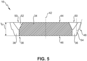
- Fig. 5 shows a cross-sectional view of the retaining device 16 comprising the basic body 34 and clamping means 36.
- the retaining device 16 comprises the circular groove 50 being arranged circumferentially around the longitudinal axis 42 of the basic body 34.
- the circular groove 50 is V-shaped 52.
- the circular groove 50 is arranged at the first side 44 of the basic body 34, only.
- the basic body 34 has a thickness t b while the clamping means 36 extend diagonally outwards from the basic body 34 in an angle 54.
Landscapes
- Engineering & Computer Science (AREA)
- Transportation (AREA)
- Mechanical Engineering (AREA)
- Braking Arrangements (AREA)
- Braking Systems And Boosters (AREA)
Claims (12)
- Federspeicherbremszylinder (2), insbesondere ein Park- oder Not-Federspeicherbremszylinder (2) zur Verwendung in einem Nutzfahrzeug, der Zylinder (2) umfassend:- ein Zylindergehäuse (4), umfassend eine Zylindergehäusebasis (6),- einen Federspeicherbremskolben (10), der sich in dem Zylindergehäuse (4) befindet, zum Ausüben einer Bremskraft,- eine Federführung (12), die an dem Federspeicherbremskolben (10) angebracht ist,- eine Kompressionsfeder (8), die sich zwischen der Zylindergehäusebasis (6) und der Federführung (12) des Federspeicherbremskolbens (10) befindet, wobei die Kompressionsfeder (8) wirksam ist, um den Federspeicherbremskolben (10) von der Basis (6) weg zu drücken,wobei die Federführung (12) ein Ventil (14) und eine Haltevorrichtung (16) zum Halten des Ventils (14) umfasst, die Haltevorrichtung (16) umfassend einen Grundkörper (34) und Klemmmittel (36) zum Klemmen der Vorrichtung (16) an die Federführung (12),dadurch gekennzeichnet, dass die Klemmmittel (36) an dem Grundkörper (34) und entlang eines Umfangs (38) des Grundkörpers (34) angeordnet sind,wobei die Klemmmittel (36) voneinander beabstandet sind, wobei Schlitze (40) zwischen den Klemmmitteln (36) ausgebildet werden, um eine Luftzirkulation durch die Schlitze (40) zu ermöglichen.
- Federspeicherbremszylinder (2) nach Anspruch 1,
dadurch gekennzeichnet, dass der Grundkörper (34) die Form einer Scheibe aufweist. - Federspeicherbremszylinder (2) nach Anspruch 1 oder 2,
dadurch gekennzeichnet, dass die Haltevorrichtung (16) eine Kreisnut (50), die um eine Längsachse (42) des Grundkörpers (34) herum umlaufend angeordnet ist, umfasst. - Federspeicherbremszylinder (2) nach Anspruch 3,
dadurch gekennzeichnet, dass die Kreisnut (50) V-förmig (52) ist. - Federspeicherbremszylinder (2) nach Anspruch 3 oder 4,
dadurch gekennzeichnet, dass die Haltevorrichtung (16) eine erste Seite (44) und eine zweite Seite (46) aufweist, wobei die zweite Seite (46) axial gegenüber der ersten Seite (44) angeordnet ist, wobei die Kreisnut (50) nur an der ersten Seite (44) angeordnet ist. - Federspeicherbremszylinder (2) nach einem der vorstehenden Ansprüche,
dadurch gekennzeichnet, dass sich die Klemmmittel (36) in einem Winkel (54) von 1° - 60° relativ zu der Längsachse (42), vorzugsweise 25 - 40°, von dem Grundkörper (34) diagonal nach außen erstrecken. - Federspeicherbremszylinder (2) nach einem der vorstehenden Ansprüche,
dadurch gekennzeichnet, dass die Klemmmittel (36) mit dem Grundkörper (34) einstückig ausgebildet sind. - Federspeicherbremszylinder (2) nach einem der vorstehenden Ansprüche,
dadurch gekennzeichnet, dass der Grundkörper (34) 5 - 20 Klemmmittel (36), vorzugsweise 8 Klemmmittel (36), umfasst. - Federspeicherbremszylinder (2) nach einem der vorstehenden Ansprüche,
dadurch gekennzeichnet, dass die Schlitze (40) zwischen den beabstandeten Klemmmitteln (36) eine Breite (ws) von 0,3 - 2 mm, vorzugsweise 0,7 mm, aufweisen. - Federspeicherbremszylinder (2) nach einem der vorstehenden Ansprüche, dadurch gekennzeichnet, dass der Grundkörper eine Dicke (tb) von 0,5 mm - 2 mm, vorzugsweise 1 mm, aufweist.
- Federspeicherbremszylinder (2) nach einem der vorstehenden Ansprüche,
dadurch gekennzeichnet, dass die Klemmmittel (36) eine Kreisschulter (48) zum Positionieren der Haltevorrichtung (16) in der Federführung (12) aufweisen. - Federspeicherbremszylinder (2) nach einem der vorstehenden Ansprüche,
dadurch gekennzeichnet, dass die Haltevorrichtung (16) partiell oder vollständig aus Blech, vorzugsweise Stahl- oder Aluminiumblech, und/oder Kunststoff, vorzugsweise kristallinem oder teilkristallinem Kunststoff, besonders bevorzugt Polypropylenterephtalat (PPT), Polyamid (PA), Polyoxymethylen (POM), Polyphthalamid (PPA) oder Polypropylen (PP) oder einer Kombination der Obengenannten hergestellt ist.
Applications Claiming Priority (1)
| Application Number | Priority Date | Filing Date | Title |
|---|---|---|---|
| PCT/EP2019/083868 WO2021110272A1 (en) | 2019-12-05 | 2019-12-05 | Spring brake actuator and retaining device for such spring brake actuator |
Publications (2)
| Publication Number | Publication Date |
|---|---|
| EP4069563A1 EP4069563A1 (de) | 2022-10-12 |
| EP4069563B1 true EP4069563B1 (de) | 2024-07-10 |
Family
ID=68841086
Family Applications (1)
| Application Number | Title | Priority Date | Filing Date |
|---|---|---|---|
| EP19817641.4A Active EP4069563B1 (de) | 2019-12-05 | 2019-12-05 | Federspeicherbremszylinder |
Country Status (3)
| Country | Link |
|---|---|
| US (1) | US12559082B2 (de) |
| EP (1) | EP4069563B1 (de) |
| WO (1) | WO2021110272A1 (de) |
Families Citing this family (3)
| Publication number | Priority date | Publication date | Assignee | Title |
|---|---|---|---|---|
| DE102023119814A1 (de) * | 2023-07-26 | 2025-01-30 | Knorr-Bremse Systeme für Nutzfahrzeuge GmbH | Druckluftbetätigter Federspeicherbremszylinder mit zentraler Atmungsvorrichtung |
| EP4650234A1 (de) | 2024-05-14 | 2025-11-19 | ZF CV Systems Europe BV | Membrananordnung für einen federspeicherbremszylinder eines druckluftbremssystems eines fahrzeugs, federspeicherbremszylinder, druckluftbremssystem und fahrzeug |
| EP4660031A1 (de) * | 2024-06-06 | 2025-12-10 | ZF CV Systems Europe BV | Trenneranordnung für einen federspeicherbremszylinder für ein druckluftbremssystem für ein fahrzeug, insbesondere nutzfahrzeug |
Family Cites Families (24)
| Publication number | Priority date | Publication date | Assignee | Title |
|---|---|---|---|---|
| US2503854A (en) * | 1947-05-15 | 1950-04-11 | Disto Corp | Snap action clamping device |
| US2630343A (en) * | 1950-04-26 | 1953-03-03 | Garlock Packing Co | Sealing device |
| US3037522A (en) * | 1958-04-04 | 1962-06-05 | Otto Items Inc | Check valve construction |
| US3331390A (en) * | 1964-07-06 | 1967-07-18 | Norgren Co C A | Check valve |
| US3954121A (en) * | 1975-03-17 | 1976-05-04 | The Weatherhead Company | Vent check valve |
| US4820409A (en) * | 1988-04-19 | 1989-04-11 | Facet Enterprises, Inc. | Plastic pressure relief valve assembly |
| EP0542568A3 (en) * | 1991-11-15 | 1993-08-04 | Bendix Limited | Spring force actuators |
| US5226291A (en) | 1991-12-17 | 1993-07-13 | General Motors Corporation | Vacuum booster diaphragm/support plate retention method |
| US6164187A (en) * | 1997-08-15 | 2000-12-26 | Holland Neway International, Inc. | Diaphragm retainer for spring brake actuator |
| AU1625499A (en) * | 1997-12-05 | 1999-06-28 | Holland Neway International, Inc. | Normally-closed diaphragm check valve |
| AU2000278521A1 (en) * | 2000-03-15 | 2001-09-24 | Holland Neway International, Inc. | Sealed brake actuator |
| US6907818B2 (en) * | 2003-10-29 | 2005-06-21 | Haldex Brake Corporation | System and method for providing dry filtered air to a brake actuator |
| US8657299B2 (en) * | 2004-07-15 | 2014-02-25 | John E. Rode | Mounting rings for shafts |
| US7461907B2 (en) * | 2005-07-18 | 2008-12-09 | Bendix Spicer Foundation Brake Llc | Rod/seal bearing arrangement utilizing locking fingers |
| US20070034465A1 (en) * | 2005-08-12 | 2007-02-15 | Larry Thompson | Flexible bushing assembly for spring brake push rod center seal |
| US20080178884A1 (en) * | 2007-01-25 | 2008-07-31 | Gerson Ronald L | Fluid Valve with Center Post |
| US9016319B2 (en) * | 2007-08-22 | 2015-04-28 | Societe Bic | Relief valves for fuel cell systems |
| US9409267B2 (en) * | 2010-06-17 | 2016-08-09 | Bendix Spicer Foundation Brake Llc | Snap-in center seal bushing |
| US8978839B2 (en) * | 2012-05-07 | 2015-03-17 | Haldex Brake Products Corporation | Pneumatic brake actuator with flow insensitive two way control valve |
| DE102012107331A1 (de) * | 2012-08-09 | 2014-02-13 | Franz Haimer Maschinenbau Kg | Auswucht- oder Messvorrichtung |
| US9487203B2 (en) * | 2013-04-10 | 2016-11-08 | G&P Automotive Co., Ltd. | Brake actuator |
| JP6330730B2 (ja) * | 2015-05-29 | 2018-05-30 | 株式会社アドヴィックス | 負圧式倍力装置 |
| DE102017119822B4 (de) * | 2017-08-29 | 2024-02-01 | Zeroclamp Gmbh | Doppelfunktion eines Zentrierkonus für eine Aufnahme einer Spannvorrichtung und Spannvorrichtung |
| US10663025B2 (en) * | 2018-07-31 | 2020-05-26 | Bendix Spicer Foundation Brake Llc | Bushing assembly for a spring brake actuator of a vehicle air braking system |
-
2019
- 2019-12-05 US US17/781,456 patent/US12559082B2/en active Active
- 2019-12-05 EP EP19817641.4A patent/EP4069563B1/de active Active
- 2019-12-05 WO PCT/EP2019/083868 patent/WO2021110272A1/en not_active Ceased
Also Published As
| Publication number | Publication date |
|---|---|
| US12559082B2 (en) | 2026-02-24 |
| WO2021110272A1 (en) | 2021-06-10 |
| US20230001911A1 (en) | 2023-01-05 |
| EP4069563A1 (de) | 2022-10-12 |
Similar Documents
| Publication | Publication Date | Title |
|---|---|---|
| EP4069563B1 (de) | Federspeicherbremszylinder | |
| EP2760720B1 (de) | Feststellbremskolben für eine feststellbremskammer | |
| US9062766B2 (en) | Locking apparatus | |
| US10864897B2 (en) | Brake device for a hydraulic motor vehicle brake system | |
| CN113544027B (zh) | 用于车辆的弹簧制动促动器,特别是用于商用车辆的驻车或紧急制动促动器 | |
| MX2014003604A (es) | Conexion directa al piston de estacionamiento a una barra apr. | |
| US20130240773A1 (en) | Valve of a piston pump with a closing body | |
| US20190249731A1 (en) | Abutment clip for disk brakes | |
| JP2018520010A (ja) | 軸のカシメ工具 | |
| US10626939B2 (en) | Adhesive attachment of the disc brake pushrod plate to the diaphragm | |
| US7390174B2 (en) | Piston pump | |
| CN102686464A (zh) | 阀组件,特别是用于机动车辆制动系统的电磁阀及制造这种阀组件的方法 | |
| US7451689B2 (en) | Combined service brake and spring brake cylinder assembly | |
| EP2639126B1 (de) | Staub- oder Steinschutzschild für die Stösselstange eines Bremsaktuators | |
| US7555902B2 (en) | Tandem master cylinder with central valves | |
| EP4023512B1 (de) | Gestanzte federaufnahme zur verwendung in einem federspeicherbremszylinder und federspeicherbremszylinder zur verwendung in nutzfahrzeugen | |
| EP3840993B1 (de) | Komponenten eines druckluftbremssteuermoduls | |
| EP4650235A1 (de) | Federspeicherbremszylinder für ein pneumatisches bremssystem eines fahrzeugs, insbesondere nutzfahrzeug, pneumatisches bremssystem, fahrzeug und verfahren | |
| US12090972B2 (en) | Spring brake actuator | |
| WO2007092481A2 (en) | Brake assembly, brake actuator and method of making a brake actuator | |
| US7287457B1 (en) | Structure for retaining a piston assembly in position relative to a cylinder | |
| CN113784879A (zh) | 用于弹簧制动促动器的活塞管组件以及弹簧制动促动器 | |
| US20160377133A1 (en) | Brake disk device for a vehicle | |
| EP4059792B1 (de) | Federbremsaktuator zur verwendung in einem fahrzeug und verwendung einer tellerfeder darin | |
| WO2025080480A1 (en) | Eccentrically mounted guide pin for air disc brake system and methods for the use and assembly thereof |
Legal Events
| Date | Code | Title | Description |
|---|---|---|---|
| STAA | Information on the status of an ep patent application or granted ep patent |
Free format text: STATUS: UNKNOWN |
|
| STAA | Information on the status of an ep patent application or granted ep patent |
Free format text: STATUS: THE INTERNATIONAL PUBLICATION HAS BEEN MADE |
|
| PUAI | Public reference made under article 153(3) epc to a published international application that has entered the european phase |
Free format text: ORIGINAL CODE: 0009012 |
|
| STAA | Information on the status of an ep patent application or granted ep patent |
Free format text: STATUS: REQUEST FOR EXAMINATION WAS MADE |
|
| 17P | Request for examination filed |
Effective date: 20220705 |
|
| AK | Designated contracting states |
Kind code of ref document: A1 Designated state(s): AL AT BE BG CH CY CZ DE DK EE ES FI FR GB GR HR HU IE IS IT LI LT LU LV MC MK MT NL NO PL PT RO RS SE SI SK SM TR |
|
| DAV | Request for validation of the european patent (deleted) | ||
| DAX | Request for extension of the european patent (deleted) | ||
| GRAP | Despatch of communication of intention to grant a patent |
Free format text: ORIGINAL CODE: EPIDOSNIGR1 |
|
| STAA | Information on the status of an ep patent application or granted ep patent |
Free format text: STATUS: GRANT OF PATENT IS INTENDED |
|
| INTG | Intention to grant announced |
Effective date: 20240314 |
|
| GRAS | Grant fee paid |
Free format text: ORIGINAL CODE: EPIDOSNIGR3 |
|
| GRAA | (expected) grant |
Free format text: ORIGINAL CODE: 0009210 |
|
| STAA | Information on the status of an ep patent application or granted ep patent |
Free format text: STATUS: THE PATENT HAS BEEN GRANTED |
|
| AK | Designated contracting states |
Kind code of ref document: B1 Designated state(s): AL AT BE BG CH CY CZ DE DK EE ES FI FR GB GR HR HU IE IS IT LI LT LU LV MC MK MT NL NO PL PT RO RS SE SI SK SM TR |
|
| REG | Reference to a national code |
Ref country code: CH Ref legal event code: EP |
|
| REG | Reference to a national code |
Ref country code: DE Ref legal event code: R096 Ref document number: 602019055069 Country of ref document: DE |
|
| REG | Reference to a national code |
Ref country code: LT Ref legal event code: MG9D |
|
| REG | Reference to a national code |
Ref country code: NL Ref legal event code: MP Effective date: 20240710 |
|
| PG25 | Lapsed in a contracting state [announced via postgrant information from national office to epo] |
Ref country code: PT Free format text: LAPSE BECAUSE OF FAILURE TO SUBMIT A TRANSLATION OF THE DESCRIPTION OR TO PAY THE FEE WITHIN THE PRESCRIBED TIME-LIMIT Effective date: 20241111 |
|
| REG | Reference to a national code |
Ref country code: AT Ref legal event code: MK05 Ref document number: 1701806 Country of ref document: AT Kind code of ref document: T Effective date: 20240710 |
|
| PG25 | Lapsed in a contracting state [announced via postgrant information from national office to epo] |
Ref country code: NL Free format text: LAPSE BECAUSE OF FAILURE TO SUBMIT A TRANSLATION OF THE DESCRIPTION OR TO PAY THE FEE WITHIN THE PRESCRIBED TIME-LIMIT Effective date: 20240710 |
|
| PG25 | Lapsed in a contracting state [announced via postgrant information from national office to epo] |
Ref country code: PT Free format text: LAPSE BECAUSE OF FAILURE TO SUBMIT A TRANSLATION OF THE DESCRIPTION OR TO PAY THE FEE WITHIN THE PRESCRIBED TIME-LIMIT Effective date: 20241111 Ref country code: NL Free format text: LAPSE BECAUSE OF FAILURE TO SUBMIT A TRANSLATION OF THE DESCRIPTION OR TO PAY THE FEE WITHIN THE PRESCRIBED TIME-LIMIT Effective date: 20240710 |
|
| PG25 | Lapsed in a contracting state [announced via postgrant information from national office to epo] |
Ref country code: NO Free format text: LAPSE BECAUSE OF FAILURE TO SUBMIT A TRANSLATION OF THE DESCRIPTION OR TO PAY THE FEE WITHIN THE PRESCRIBED TIME-LIMIT Effective date: 20241010 |
|
| PG25 | Lapsed in a contracting state [announced via postgrant information from national office to epo] |
Ref country code: GR Free format text: LAPSE BECAUSE OF FAILURE TO SUBMIT A TRANSLATION OF THE DESCRIPTION OR TO PAY THE FEE WITHIN THE PRESCRIBED TIME-LIMIT Effective date: 20241011 Ref country code: FI Free format text: LAPSE BECAUSE OF FAILURE TO SUBMIT A TRANSLATION OF THE DESCRIPTION OR TO PAY THE FEE WITHIN THE PRESCRIBED TIME-LIMIT Effective date: 20240710 Ref country code: PL Free format text: LAPSE BECAUSE OF FAILURE TO SUBMIT A TRANSLATION OF THE DESCRIPTION OR TO PAY THE FEE WITHIN THE PRESCRIBED TIME-LIMIT Effective date: 20240710 |
|
| PG25 | Lapsed in a contracting state [announced via postgrant information from national office to epo] |
Ref country code: BG Free format text: LAPSE BECAUSE OF FAILURE TO SUBMIT A TRANSLATION OF THE DESCRIPTION OR TO PAY THE FEE WITHIN THE PRESCRIBED TIME-LIMIT Effective date: 20240710 |
|
| PG25 | Lapsed in a contracting state [announced via postgrant information from national office to epo] |
Ref country code: LV Free format text: LAPSE BECAUSE OF FAILURE TO SUBMIT A TRANSLATION OF THE DESCRIPTION OR TO PAY THE FEE WITHIN THE PRESCRIBED TIME-LIMIT Effective date: 20240710 |
|
| PG25 | Lapsed in a contracting state [announced via postgrant information from national office to epo] |
Ref country code: IS Free format text: LAPSE BECAUSE OF FAILURE TO SUBMIT A TRANSLATION OF THE DESCRIPTION OR TO PAY THE FEE WITHIN THE PRESCRIBED TIME-LIMIT Effective date: 20241110 Ref country code: AT Free format text: LAPSE BECAUSE OF FAILURE TO SUBMIT A TRANSLATION OF THE DESCRIPTION OR TO PAY THE FEE WITHIN THE PRESCRIBED TIME-LIMIT Effective date: 20240710 |
|
| PG25 | Lapsed in a contracting state [announced via postgrant information from national office to epo] |
Ref country code: HR Free format text: LAPSE BECAUSE OF FAILURE TO SUBMIT A TRANSLATION OF THE DESCRIPTION OR TO PAY THE FEE WITHIN THE PRESCRIBED TIME-LIMIT Effective date: 20240710 |
|
| PG25 | Lapsed in a contracting state [announced via postgrant information from national office to epo] |
Ref country code: ES Free format text: LAPSE BECAUSE OF FAILURE TO SUBMIT A TRANSLATION OF THE DESCRIPTION OR TO PAY THE FEE WITHIN THE PRESCRIBED TIME-LIMIT Effective date: 20240710 Ref country code: RS Free format text: LAPSE BECAUSE OF FAILURE TO SUBMIT A TRANSLATION OF THE DESCRIPTION OR TO PAY THE FEE WITHIN THE PRESCRIBED TIME-LIMIT Effective date: 20241010 |
|
| PG25 | Lapsed in a contracting state [announced via postgrant information from national office to epo] |
Ref country code: RS Free format text: LAPSE BECAUSE OF FAILURE TO SUBMIT A TRANSLATION OF THE DESCRIPTION OR TO PAY THE FEE WITHIN THE PRESCRIBED TIME-LIMIT Effective date: 20241010 Ref country code: PL Free format text: LAPSE BECAUSE OF FAILURE TO SUBMIT A TRANSLATION OF THE DESCRIPTION OR TO PAY THE FEE WITHIN THE PRESCRIBED TIME-LIMIT Effective date: 20240710 Ref country code: NO Free format text: LAPSE BECAUSE OF FAILURE TO SUBMIT A TRANSLATION OF THE DESCRIPTION OR TO PAY THE FEE WITHIN THE PRESCRIBED TIME-LIMIT Effective date: 20241010 Ref country code: LV Free format text: LAPSE BECAUSE OF FAILURE TO SUBMIT A TRANSLATION OF THE DESCRIPTION OR TO PAY THE FEE WITHIN THE PRESCRIBED TIME-LIMIT Effective date: 20240710 Ref country code: IS Free format text: LAPSE BECAUSE OF FAILURE TO SUBMIT A TRANSLATION OF THE DESCRIPTION OR TO PAY THE FEE WITHIN THE PRESCRIBED TIME-LIMIT Effective date: 20241110 Ref country code: HR Free format text: LAPSE BECAUSE OF FAILURE TO SUBMIT A TRANSLATION OF THE DESCRIPTION OR TO PAY THE FEE WITHIN THE PRESCRIBED TIME-LIMIT Effective date: 20240710 Ref country code: GR Free format text: LAPSE BECAUSE OF FAILURE TO SUBMIT A TRANSLATION OF THE DESCRIPTION OR TO PAY THE FEE WITHIN THE PRESCRIBED TIME-LIMIT Effective date: 20241011 Ref country code: FI Free format text: LAPSE BECAUSE OF FAILURE TO SUBMIT A TRANSLATION OF THE DESCRIPTION OR TO PAY THE FEE WITHIN THE PRESCRIBED TIME-LIMIT Effective date: 20240710 Ref country code: ES Free format text: LAPSE BECAUSE OF FAILURE TO SUBMIT A TRANSLATION OF THE DESCRIPTION OR TO PAY THE FEE WITHIN THE PRESCRIBED TIME-LIMIT Effective date: 20240710 Ref country code: BG Free format text: LAPSE BECAUSE OF FAILURE TO SUBMIT A TRANSLATION OF THE DESCRIPTION OR TO PAY THE FEE WITHIN THE PRESCRIBED TIME-LIMIT Effective date: 20240710 Ref country code: AT Free format text: LAPSE BECAUSE OF FAILURE TO SUBMIT A TRANSLATION OF THE DESCRIPTION OR TO PAY THE FEE WITHIN THE PRESCRIBED TIME-LIMIT Effective date: 20240710 |
|
| REG | Reference to a national code |
Ref country code: DE Ref legal event code: R097 Ref document number: 602019055069 Country of ref document: DE |
|
| PG25 | Lapsed in a contracting state [announced via postgrant information from national office to epo] |
Ref country code: RO Free format text: LAPSE BECAUSE OF FAILURE TO SUBMIT A TRANSLATION OF THE DESCRIPTION OR TO PAY THE FEE WITHIN THE PRESCRIBED TIME-LIMIT Effective date: 20240710 Ref country code: DK Free format text: LAPSE BECAUSE OF FAILURE TO SUBMIT A TRANSLATION OF THE DESCRIPTION OR TO PAY THE FEE WITHIN THE PRESCRIBED TIME-LIMIT Effective date: 20240710 Ref country code: SM Free format text: LAPSE BECAUSE OF FAILURE TO SUBMIT A TRANSLATION OF THE DESCRIPTION OR TO PAY THE FEE WITHIN THE PRESCRIBED TIME-LIMIT Effective date: 20240710 |
|
| PG25 | Lapsed in a contracting state [announced via postgrant information from national office to epo] |
Ref country code: EE Free format text: LAPSE BECAUSE OF FAILURE TO SUBMIT A TRANSLATION OF THE DESCRIPTION OR TO PAY THE FEE WITHIN THE PRESCRIBED TIME-LIMIT Effective date: 20240710 |
|
| PG25 | Lapsed in a contracting state [announced via postgrant information from national office to epo] |
Ref country code: CZ Free format text: LAPSE BECAUSE OF FAILURE TO SUBMIT A TRANSLATION OF THE DESCRIPTION OR TO PAY THE FEE WITHIN THE PRESCRIBED TIME-LIMIT Effective date: 20240710 |
|
| PG25 | Lapsed in a contracting state [announced via postgrant information from national office to epo] |
Ref country code: SK Free format text: LAPSE BECAUSE OF FAILURE TO SUBMIT A TRANSLATION OF THE DESCRIPTION OR TO PAY THE FEE WITHIN THE PRESCRIBED TIME-LIMIT Effective date: 20240710 Ref country code: IT Free format text: LAPSE BECAUSE OF FAILURE TO SUBMIT A TRANSLATION OF THE DESCRIPTION OR TO PAY THE FEE WITHIN THE PRESCRIBED TIME-LIMIT Effective date: 20240710 |
|
| PLBE | No opposition filed within time limit |
Free format text: ORIGINAL CODE: 0009261 |
|
| STAA | Information on the status of an ep patent application or granted ep patent |
Free format text: STATUS: NO OPPOSITION FILED WITHIN TIME LIMIT |
|
| 26N | No opposition filed |
Effective date: 20250411 |
|
| PG25 | Lapsed in a contracting state [announced via postgrant information from national office to epo] |
Ref country code: MC Free format text: LAPSE BECAUSE OF FAILURE TO SUBMIT A TRANSLATION OF THE DESCRIPTION OR TO PAY THE FEE WITHIN THE PRESCRIBED TIME-LIMIT Effective date: 20240710 |
|
| REG | Reference to a national code |
Ref country code: CH Ref legal event code: PL |
|
| PG25 | Lapsed in a contracting state [announced via postgrant information from national office to epo] |
Ref country code: LU Free format text: LAPSE BECAUSE OF NON-PAYMENT OF DUE FEES Effective date: 20241205 |
|
| GBPC | Gb: european patent ceased through non-payment of renewal fee |
Effective date: 20241205 |
|
| PG25 | Lapsed in a contracting state [announced via postgrant information from national office to epo] |
Ref country code: SE Free format text: LAPSE BECAUSE OF FAILURE TO SUBMIT A TRANSLATION OF THE DESCRIPTION OR TO PAY THE FEE WITHIN THE PRESCRIBED TIME-LIMIT Effective date: 20240710 |
|
| REG | Reference to a national code |
Ref country code: BE Ref legal event code: MM Effective date: 20241231 |
|
| PG25 | Lapsed in a contracting state [announced via postgrant information from national office to epo] |
Ref country code: BE Free format text: LAPSE BECAUSE OF NON-PAYMENT OF DUE FEES Effective date: 20241231 Ref country code: GB Free format text: LAPSE BECAUSE OF NON-PAYMENT OF DUE FEES Effective date: 20241205 |
|
| PG25 | Lapsed in a contracting state [announced via postgrant information from national office to epo] |
Ref country code: FR Free format text: LAPSE BECAUSE OF NON-PAYMENT OF DUE FEES Effective date: 20241231 |
|
| PG25 | Lapsed in a contracting state [announced via postgrant information from national office to epo] |
Ref country code: CH Free format text: LAPSE BECAUSE OF NON-PAYMENT OF DUE FEES Effective date: 20241231 |
|
| PG25 | Lapsed in a contracting state [announced via postgrant information from national office to epo] |
Ref country code: IE Free format text: LAPSE BECAUSE OF NON-PAYMENT OF DUE FEES Effective date: 20241205 |
|
| PGFP | Annual fee paid to national office [announced via postgrant information from national office to epo] |
Ref country code: DE Payment date: 20250930 Year of fee payment: 7 |
|
| PG25 | Lapsed in a contracting state [announced via postgrant information from national office to epo] |
Ref country code: CY Free format text: LAPSE BECAUSE OF FAILURE TO SUBMIT A TRANSLATION OF THE DESCRIPTION OR TO PAY THE FEE WITHIN THE PRESCRIBED TIME-LIMIT; INVALID AB INITIO Effective date: 20191205 |