EP4069414B1 - Dispositif de chauffage de gaz - Google Patents
Dispositif de chauffage de gaz Download PDFInfo
- Publication number
- EP4069414B1 EP4069414B1 EP20816478.0A EP20816478A EP4069414B1 EP 4069414 B1 EP4069414 B1 EP 4069414B1 EP 20816478 A EP20816478 A EP 20816478A EP 4069414 B1 EP4069414 B1 EP 4069414B1
- Authority
- EP
- European Patent Office
- Prior art keywords
- structured body
- heating
- heating system
- gas
- pressure shell
- Prior art date
- Legal status (The legal status is an assumption and is not a legal conclusion. Google has not performed a legal analysis and makes no representation as to the accuracy of the status listed.)
- Active
Links
- 238000010438 heat treatment Methods 0.000 claims description 197
- 239000004020 conductor Substances 0.000 claims description 134
- 238000000034 method Methods 0.000 claims description 52
- 239000000463 material Substances 0.000 claims description 45
- 230000008569 process Effects 0.000 claims description 39
- 238000005524 ceramic coating Methods 0.000 claims description 36
- 238000009413 insulation Methods 0.000 claims description 18
- 230000004907 flux Effects 0.000 claims description 15
- 230000015572 biosynthetic process Effects 0.000 claims description 13
- 238000003786 synthesis reaction Methods 0.000 claims description 13
- 239000000203 mixture Substances 0.000 claims description 11
- 239000003054 catalyst Substances 0.000 claims description 4
- 239000010410 layer Substances 0.000 description 19
- XEEYBQQBJWHFJM-UHFFFAOYSA-N iron Substances [Fe] XEEYBQQBJWHFJM-UHFFFAOYSA-N 0.000 description 12
- 229910045601 alloy Inorganic materials 0.000 description 11
- 239000000956 alloy Substances 0.000 description 11
- 230000001427 coherent effect Effects 0.000 description 11
- 239000011810 insulating material Substances 0.000 description 11
- 229910052751 metal Inorganic materials 0.000 description 11
- 239000002184 metal Substances 0.000 description 11
- PXHVJJICTQNCMI-UHFFFAOYSA-N nickel Substances [Ni] PXHVJJICTQNCMI-UHFFFAOYSA-N 0.000 description 10
- CURLTUGMZLYLDI-UHFFFAOYSA-N Carbon dioxide Chemical compound O=C=O CURLTUGMZLYLDI-UHFFFAOYSA-N 0.000 description 9
- 230000008859 change Effects 0.000 description 9
- 238000006243 chemical reaction Methods 0.000 description 9
- 229910052782 aluminium Inorganic materials 0.000 description 8
- 229910002092 carbon dioxide Inorganic materials 0.000 description 8
- 238000004519 manufacturing process Methods 0.000 description 8
- 238000010146 3D printing Methods 0.000 description 7
- 238000013461 design Methods 0.000 description 7
- 238000005516 engineering process Methods 0.000 description 7
- 229910052742 iron Inorganic materials 0.000 description 7
- 238000005245 sintering Methods 0.000 description 7
- 239000000126 substance Substances 0.000 description 7
- 229910052799 carbon Inorganic materials 0.000 description 6
- 238000000576 coating method Methods 0.000 description 6
- 238000002474 experimental method Methods 0.000 description 6
- 239000000654 additive Substances 0.000 description 5
- 230000000996 additive effect Effects 0.000 description 5
- XAGFODPZIPBFFR-UHFFFAOYSA-N aluminium Chemical compound [Al] XAGFODPZIPBFFR-UHFFFAOYSA-N 0.000 description 5
- 239000011248 coating agent Substances 0.000 description 5
- 229910052802 copper Inorganic materials 0.000 description 5
- 239000010949 copper Substances 0.000 description 5
- 229910052759 nickel Inorganic materials 0.000 description 5
- 230000007704 transition Effects 0.000 description 5
- QGZKDVFQNNGYKY-UHFFFAOYSA-N Ammonia Chemical compound N QGZKDVFQNNGYKY-UHFFFAOYSA-N 0.000 description 4
- RYGMFSIKBFXOCR-UHFFFAOYSA-N Copper Chemical compound [Cu] RYGMFSIKBFXOCR-UHFFFAOYSA-N 0.000 description 4
- 229910010293 ceramic material Inorganic materials 0.000 description 4
- 230000000052 comparative effect Effects 0.000 description 4
- 230000001276 controlling effect Effects 0.000 description 4
- 238000005137 deposition process Methods 0.000 description 4
- 230000004927 fusion Effects 0.000 description 4
- VNWKTOKETHGBQD-UHFFFAOYSA-N methane Chemical compound C VNWKTOKETHGBQD-UHFFFAOYSA-N 0.000 description 4
- 239000008188 pellet Substances 0.000 description 4
- 239000000843 powder Substances 0.000 description 4
- 238000011144 upstream manufacturing Methods 0.000 description 4
- XLYOFNOQVPJJNP-UHFFFAOYSA-N water Substances O XLYOFNOQVPJJNP-UHFFFAOYSA-N 0.000 description 4
- 229910052727 yttrium Inorganic materials 0.000 description 4
- PNEYBMLMFCGWSK-UHFFFAOYSA-N aluminium oxide Inorganic materials [O-2].[O-2].[O-2].[Al+3].[Al+3] PNEYBMLMFCGWSK-UHFFFAOYSA-N 0.000 description 3
- 230000008901 benefit Effects 0.000 description 3
- 239000000919 ceramic Substances 0.000 description 3
- 229910052804 chromium Inorganic materials 0.000 description 3
- 239000011651 chromium Substances 0.000 description 3
- 230000000875 corresponding effect Effects 0.000 description 3
- 239000012777 electrically insulating material Substances 0.000 description 3
- 230000005611 electricity Effects 0.000 description 3
- 238000002844 melting Methods 0.000 description 3
- 230000008018 melting Effects 0.000 description 3
- 230000001590 oxidative effect Effects 0.000 description 3
- 230000002441 reversible effect Effects 0.000 description 3
- 239000007787 solid Substances 0.000 description 3
- 238000000629 steam reforming Methods 0.000 description 3
- 229910052726 zirconium Inorganic materials 0.000 description 3
- OKTJSMMVPCPJKN-UHFFFAOYSA-N Carbon Chemical compound [C] OKTJSMMVPCPJKN-UHFFFAOYSA-N 0.000 description 2
- VYZAMTAEIAYCRO-UHFFFAOYSA-N Chromium Chemical compound [Cr] VYZAMTAEIAYCRO-UHFFFAOYSA-N 0.000 description 2
- BQCADISMDOOEFD-UHFFFAOYSA-N Silver Chemical compound [Ag] BQCADISMDOOEFD-UHFFFAOYSA-N 0.000 description 2
- MCMNRKCIXSYSNV-UHFFFAOYSA-N Zirconium dioxide Chemical compound O=[Zr]=O MCMNRKCIXSYSNV-UHFFFAOYSA-N 0.000 description 2
- 229910021529 ammonia Inorganic materials 0.000 description 2
- 239000011230 binding agent Substances 0.000 description 2
- 239000011449 brick Substances 0.000 description 2
- 230000006835 compression Effects 0.000 description 2
- 238000007906 compression Methods 0.000 description 2
- 239000000470 constituent Substances 0.000 description 2
- 238000001816 cooling Methods 0.000 description 2
- 230000002596 correlated effect Effects 0.000 description 2
- 229910052593 corundum Inorganic materials 0.000 description 2
- 230000003247 decreasing effect Effects 0.000 description 2
- 238000011143 downstream manufacturing Methods 0.000 description 2
- 230000000694 effects Effects 0.000 description 2
- 238000005868 electrolysis reaction Methods 0.000 description 2
- 238000010894 electron beam technology Methods 0.000 description 2
- 229910000953 kanthal Inorganic materials 0.000 description 2
- 229910052748 manganese Inorganic materials 0.000 description 2
- 150000002739 metals Chemical class 0.000 description 2
- 238000002156 mixing Methods 0.000 description 2
- 229910052750 molybdenum Inorganic materials 0.000 description 2
- 230000005855 radiation Effects 0.000 description 2
- 230000002829 reductive effect Effects 0.000 description 2
- 238000002407 reforming Methods 0.000 description 2
- 229910052710 silicon Inorganic materials 0.000 description 2
- 229910052709 silver Inorganic materials 0.000 description 2
- 239000004332 silver Substances 0.000 description 2
- 238000009827 uniform distribution Methods 0.000 description 2
- 238000010977 unit operation Methods 0.000 description 2
- 229910001845 yogo sapphire Inorganic materials 0.000 description 2
- 208000031872 Body Remains Diseases 0.000 description 1
- 229910014780 CaAl2 Inorganic materials 0.000 description 1
- 239000004215 Carbon black (E152) Substances 0.000 description 1
- 229910000831 Steel Inorganic materials 0.000 description 1
- 230000004913 activation Effects 0.000 description 1
- 239000011149 active material Substances 0.000 description 1
- SNAAJJQQZSMGQD-UHFFFAOYSA-N aluminum magnesium Chemical compound [Mg].[Al] SNAAJJQQZSMGQD-UHFFFAOYSA-N 0.000 description 1
- 238000013459 approach Methods 0.000 description 1
- 230000004888 barrier function Effects 0.000 description 1
- 239000011575 calcium Substances 0.000 description 1
- XFWJKVMFIVXPKK-UHFFFAOYSA-N calcium;oxido(oxo)alumane Chemical compound [Ca+2].[O-][Al]=O.[O-][Al]=O XFWJKVMFIVXPKK-UHFFFAOYSA-N 0.000 description 1
- 239000001569 carbon dioxide Substances 0.000 description 1
- 238000001311 chemical methods and process Methods 0.000 description 1
- 238000009833 condensation Methods 0.000 description 1
- 230000005494 condensation Effects 0.000 description 1
- 238000010276 construction Methods 0.000 description 1
- 230000001419 dependent effect Effects 0.000 description 1
- 238000001514 detection method Methods 0.000 description 1
- 230000001627 detrimental effect Effects 0.000 description 1
- 238000009826 distribution Methods 0.000 description 1
- 238000005485 electric heating Methods 0.000 description 1
- 238000010292 electrical insulation Methods 0.000 description 1
- 238000004146 energy storage Methods 0.000 description 1
- 238000011067 equilibration Methods 0.000 description 1
- 238000001125 extrusion Methods 0.000 description 1
- 239000002657 fibrous material Substances 0.000 description 1
- 229910002804 graphite Inorganic materials 0.000 description 1
- 239000010439 graphite Substances 0.000 description 1
- 230000020169 heat generation Effects 0.000 description 1
- 229930195733 hydrocarbon Natural products 0.000 description 1
- 150000002430 hydrocarbons Chemical class 0.000 description 1
- 230000010354 integration Effects 0.000 description 1
- 230000003993 interaction Effects 0.000 description 1
- 230000002452 interceptive effect Effects 0.000 description 1
- 229910052746 lanthanum Inorganic materials 0.000 description 1
- 239000000155 melt Substances 0.000 description 1
- 238000010309 melting process Methods 0.000 description 1
- 239000013528 metallic particle Substances 0.000 description 1
- 238000012986 modification Methods 0.000 description 1
- 230000004048 modification Effects 0.000 description 1
- 230000000704 physical effect Effects 0.000 description 1
- 239000004033 plastic Substances 0.000 description 1
- 239000011148 porous material Substances 0.000 description 1
- 238000011112 process operation Methods 0.000 description 1
- 239000011241 protective layer Substances 0.000 description 1
- 238000010926 purge Methods 0.000 description 1
- 238000000746 purification Methods 0.000 description 1
- 230000009257 reactivity Effects 0.000 description 1
- 230000009467 reduction Effects 0.000 description 1
- 238000005476 soldering Methods 0.000 description 1
- 239000011343 solid material Substances 0.000 description 1
- 229910052596 spinel Inorganic materials 0.000 description 1
- 239000011029 spinel Substances 0.000 description 1
- 239000010935 stainless steel Substances 0.000 description 1
- 229910001220 stainless steel Inorganic materials 0.000 description 1
- 238000001991 steam methane reforming Methods 0.000 description 1
- 239000010959 steel Substances 0.000 description 1
- 238000006557 surface reaction Methods 0.000 description 1
- 238000012546 transfer Methods 0.000 description 1
- 238000003466 welding Methods 0.000 description 1
Images


Classifications
-
- B—PERFORMING OPERATIONS; TRANSPORTING
- B01—PHYSICAL OR CHEMICAL PROCESSES OR APPARATUS IN GENERAL
- B01J—CHEMICAL OR PHYSICAL PROCESSES, e.g. CATALYSIS OR COLLOID CHEMISTRY; THEIR RELEVANT APPARATUS
- B01J3/00—Processes of utilising sub-atmospheric or super-atmospheric pressure to effect chemical or physical change of matter; Apparatus therefor
- B01J3/04—Pressure vessels, e.g. autoclaves
-
- B—PERFORMING OPERATIONS; TRANSPORTING
- B01—PHYSICAL OR CHEMICAL PROCESSES OR APPARATUS IN GENERAL
- B01J—CHEMICAL OR PHYSICAL PROCESSES, e.g. CATALYSIS OR COLLOID CHEMISTRY; THEIR RELEVANT APPARATUS
- B01J19/00—Chemical, physical or physico-chemical processes in general; Their relevant apparatus
- B01J19/32—Packing elements in the form of grids or built-up elements for forming a unit or module inside the apparatus for mass or heat transfer
-
- B—PERFORMING OPERATIONS; TRANSPORTING
- B01—PHYSICAL OR CHEMICAL PROCESSES OR APPARATUS IN GENERAL
- B01J—CHEMICAL OR PHYSICAL PROCESSES, e.g. CATALYSIS OR COLLOID CHEMISTRY; THEIR RELEVANT APPARATUS
- B01J12/00—Chemical processes in general for reacting gaseous media with gaseous media; Apparatus specially adapted therefor
- B01J12/005—Chemical processes in general for reacting gaseous media with gaseous media; Apparatus specially adapted therefor carried out at high temperatures, e.g. by pyrolysis
-
- B—PERFORMING OPERATIONS; TRANSPORTING
- B01—PHYSICAL OR CHEMICAL PROCESSES OR APPARATUS IN GENERAL
- B01J—CHEMICAL OR PHYSICAL PROCESSES, e.g. CATALYSIS OR COLLOID CHEMISTRY; THEIR RELEVANT APPARATUS
- B01J19/00—Chemical, physical or physico-chemical processes in general; Their relevant apparatus
- B01J19/0006—Controlling or regulating processes
- B01J19/0013—Controlling the temperature of the process
-
- B—PERFORMING OPERATIONS; TRANSPORTING
- B01—PHYSICAL OR CHEMICAL PROCESSES OR APPARATUS IN GENERAL
- B01J—CHEMICAL OR PHYSICAL PROCESSES, e.g. CATALYSIS OR COLLOID CHEMISTRY; THEIR RELEVANT APPARATUS
- B01J6/00—Heat treatments such as Calcining; Fusing ; Pyrolysis
-
- B—PERFORMING OPERATIONS; TRANSPORTING
- B01—PHYSICAL OR CHEMICAL PROCESSES OR APPARATUS IN GENERAL
- B01J—CHEMICAL OR PHYSICAL PROCESSES, e.g. CATALYSIS OR COLLOID CHEMISTRY; THEIR RELEVANT APPARATUS
- B01J7/00—Apparatus for generating gases
-
- B—PERFORMING OPERATIONS; TRANSPORTING
- B01—PHYSICAL OR CHEMICAL PROCESSES OR APPARATUS IN GENERAL
- B01J—CHEMICAL OR PHYSICAL PROCESSES, e.g. CATALYSIS OR COLLOID CHEMISTRY; THEIR RELEVANT APPARATUS
- B01J2219/00—Chemical, physical or physico-chemical processes in general; Their relevant apparatus
- B01J2219/00049—Controlling or regulating processes
- B01J2219/00051—Controlling the temperature
- B01J2219/00132—Controlling the temperature using electric heating or cooling elements
- B01J2219/00135—Electric resistance heaters
-
- B—PERFORMING OPERATIONS; TRANSPORTING
- B01—PHYSICAL OR CHEMICAL PROCESSES OR APPARATUS IN GENERAL
- B01J—CHEMICAL OR PHYSICAL PROCESSES, e.g. CATALYSIS OR COLLOID CHEMISTRY; THEIR RELEVANT APPARATUS
- B01J2219/00—Chemical, physical or physico-chemical processes in general; Their relevant apparatus
- B01J2219/00049—Controlling or regulating processes
- B01J2219/00051—Controlling the temperature
- B01J2219/0015—Controlling the temperature by thermal insulation means
-
- B—PERFORMING OPERATIONS; TRANSPORTING
- B01—PHYSICAL OR CHEMICAL PROCESSES OR APPARATUS IN GENERAL
- B01J—CHEMICAL OR PHYSICAL PROCESSES, e.g. CATALYSIS OR COLLOID CHEMISTRY; THEIR RELEVANT APPARATUS
- B01J2219/00—Chemical, physical or physico-chemical processes in general; Their relevant apparatus
- B01J2219/24—Stationary reactors without moving elements inside
-
- B—PERFORMING OPERATIONS; TRANSPORTING
- B01—PHYSICAL OR CHEMICAL PROCESSES OR APPARATUS IN GENERAL
- B01J—CHEMICAL OR PHYSICAL PROCESSES, e.g. CATALYSIS OR COLLOID CHEMISTRY; THEIR RELEVANT APPARATUS
- B01J2219/00—Chemical, physical or physico-chemical processes in general; Their relevant apparatus
- B01J2219/32—Details relating to packing elements in the form of grids or built-up elements for forming a unit of module inside the apparatus for mass or heat transfer
- B01J2219/324—Composition or microstructure of the elements
Definitions
- a heating system and a process for carrying out heating of a pressurized feed gas are provided, where the heat is provided by resistance heating.
- gas heat exchangers are limited in design temperature, as they are also pressure baring equipment, which typically limits the maximum operating temperature of these.
- a classical configuration of heat exchange is the tube and shell type, where one gas flowing on the tube side heat exchanges with another gas on the shell side to thereby heat the first gas and cool the second gas, or vice versa. It is desirable to develop a heating system, specifically a gas preheater, which allows for heating gas systems to very high temperatures. It is also desirable to develop a heating system which is compact and simple to operate. Another advantage of the present technology is that the overall emission of carbon dioxide and other emissions detrimental to the climate may be reduced considerably, in particular if the power used in the heating system is from renewable energy resources.
- Preheating of gas is needed in many aspects of chemical process design.
- gas preheaters includes preheating for reduction gas used for activation of catalyst beds.
- Another use of a gas preheater is the example of a COz preheater to an Adiabatic POst Convertor (APOC).
- APOC Adiabatic POst Convertor
- the APOC reactor is described in WO 2019/110267 . In both cases, it can be desirable to have a very high gas preheating temperature to enable the interplay of the downstream unit operation.
- WO 2019/110268 A1 discloses a pressure vessel adapted to work as an electric and continuous gas pre heater at temperatures of 500, 1000 °C and above.
- the present technology thus provides a heating system for heating of a feed gas, said heating system comprising:
- the present technology describes how an electrically heated system can facilitate the task of heating gas in a compact design in an on-demand approach.
- a compact electric heating system using a structured body can easily be operated and use easy start-up principles when needed. This gives a relative inexpensive plant.
- a heating system for heating of a feed gas comprising:
- the layout of the heating system allows for feeding a pressurized feed gas to the heating system at an inlet and directing this gas into the pressure shell of the heating system.
- a configuration of heat insulation layers and inert material is arranged to direct the feed gas through the structured body. The heated gas from the heated structured body is led to the heating system outlet.
- the electrical power supply and the structured body are dimensioned so that at least part of the structured body reaches a temperature of at least 700°C, preferably at least 900°C, more preferably at least 1000°C.
- the surface area of the electrically conductive material, the fraction of the electrically conductive material coated with an - optional - ceramic coating, and the type and structure of the ceramic coating may be tailored to the specific operating conditions.
- the heated gas exiting the heating system at the outlet may have substantially the same chemical composition and molar flow rate at the feed gas, as no chemical reaction takes place in the heating system.
- the heated gas is selected from the group consisting of N 2 , H 2 , COz, CH 4 , H 2 O, Oz, and a mixture thereof.
- the electrically conductive material is suitably a macroscopic structure.
- the term "macroscopic structure” is meant to denote a structure that is large enough to be visible with the naked eye, without magnifying devices.
- the dimensions of the macroscopic structure are typically in the range of centimeters or even meters. Dimensions of the macroscopic structure are advantageously made to correspond at least partly to the inner dimensions of the pressure shell housing the structured body, saving room for the heat insulation layer and conductors.
- Two or more macroscopic structures may be connected in order to provide an array of macroscopic structures having at least one of the outer dimensions in the range of meters, such as 2 m or 5 m. Such two or more macroscopic structures may be denoted "an array of macroscopic structures”.
- an array of macroscopic structures are advantageously made to correspond at least partly to the inner dimension of the pressure shell housing the structured body (saving room for the heat insulation layer).
- a conceivable array of macroscopic structures could take up a volume of 0.1 to 10 m 3 or even larger.
- the structured body may comprise a single macroscopic structure or an array of macroscopic structures, where the macroscopic structure(s) support(s) an optional ceramic coating.
- the macroscopic structures may be electrically connected to each other; however, alternatively, the macroscopic structures are not electrically connected to each other.
- the structured body may comprise two or more macroscopic structures positioned adjacent to each other.
- the macroscopic structure(s) may be extruded and sintered structures or 3D printed structures.
- a 3D printed macroscopic structure can be provided with or without subsequent sintering.
- the ceramic coating does not support a catalytically active material.
- the ceramic coating may be applied to maintain a chemical inert environment to thereby limit or even avoid surface reactions on the metal surfaces of the macroscopic structure(s).
- the physical dimensions of the macroscopic structure may be any appropriate dimensions; thus, the height may be smaller than the width of the macroscopic structure or vice versa.
- the macroscopic structure may support a ceramic coating, which can provide a protective layer on the macroscopic structure.
- the term "macroscopic structure supporting a ceramic coating” is meant to denote that the macroscopic structure is coated by the ceramic coating at, at least, a part of the surface of the macroscopic structure. Thus, the term does not imply that all the surface of the macroscopic structure is coated by the ceramic coating; in particular, at least the parts of the macroscopic structure which are electrically connected to the conductors do not have a coating thereon.
- the coating is a ceramic material with pores in the structure.
- the macroscopic structure has been manufactured by extrusion of a mixture of powdered metallic particles and a binder to an extruded structure and subsequent sintering of the extruded structure, thereby providing a material with a high geometric surface area per volume.
- the extruded structure is sintered in a reducing atmosphere to provide the macroscopic structure.
- the macroscopic structure is 3D printed a metal additive manufacturing melting process, viz. a 3D printing processes, which do not require subsequent sintering, such as powder bed fusion or direct energy deposition processes. Examples of such powder bed fusion or direct energy deposition processes are laser beam, electron beam or plasma 3D printing processes.
- the macroscopic structure may have been manufactured as a 3D metal structure by means of a binder-based metal additive manufacturing process, and subsequent sintered in a non-oxidizing atmosphere at a first temperature T 1 , where T 1 > 1000°C, in order to provide the macroscopic structure.
- a ceramic coating may be provided onto the macroscopic structure before a second sintering in an oxidizing atmosphere, in order to form chemical bonds between the ceramic coating and the macroscopic structure.
- 3D print and “3D printing” is meant to denote a metal additive manufacturing process.
- metal additive manufacturing processes cover 3D printing processes in which material is joined to a structure under computer control to create a three-dimensional object, where the structure is to be solidified, e.g. by sintering, to provide the macroscopic structure.
- metal additive manufacturing processes cover 3D printing processes, which do not require subsequent sintering, such as powder bed fusion or direct energy deposition processes. Examples of such powder bed fusion or direct energy deposition processes are laser beam, electron beam or plasma 3D printing processes.
- the heating system does not need a furnace and this reduces the overall size considerably.
- the electrically conductive material comprises Fe, Ni, Cu, Co, Cr, Al, Si or an alloy thereof. Such an alloy may comprise further elements, such as Mn, Y, Zr, C, Co, Mo or combinations thereof. Preferably, the electrically conductive material comprises Fe, Cr, Al or an alloy thereof. Such an alloy may comprise further elements, such as Si, Mn, Y, Zr, C, Co, Mo or combinations thereof. Preferably, the conductors and the electrically conductive material are made of different materials than the electrically conductive material. The conductors may for example be of iron, nickel, aluminum, copper, silver or an alloy thereof.
- the ceramic coating is an electrically insulating material and will typically have a thickness in the range of around 100 ⁇ m, say 10-500 ⁇ m.
- the electrically conductive material is advantageously a coherent or consistently intra-connected material in order to achieve electrical conductivity throughout the electrically conductive material, and thereby achieve thermal conductivity throughout the structured body.
- coherent or consistently intra-connected material it is possible to ensure uniform distribution of current within the electrically conductive material and thus uniform distribution of heat within the structured body.
- cohesive is meant to be synonymous to cohesive and thus refer to a material that is consistently intra-connected or consistently coupled.
- the effect of the structured body being a coherent or consistently intra-connected material is that a control over the connectivity within the material of the structured body and thus the conductivity of the electrically conductive material is obtained.
- the electrically conductive material is still denoted a coherent or consistently intra-connected material.
- the gas flow over the structured body may be axial or co-axial with the current path through the structured body, perpendicular to the current path or have any other appropriate direction in relation to the current path.
- the feedstock may be substantially pure streams of steam and a hydrocarbon, alternatively it may be a pure COz or pure H 2 .
- the feedstock to the heating process may include recycle streams from unit operations downstream the heating system.
- the feed gas may be substantially pure COz, which is heated to 800°C, or even 1000°C, or even 1200°C.
- the heated COz may after outlet from the heating system be mixed with a hot synthesis gas and equilibrated according to steam methane reforming, methanation and reverse water gas shift reactions in an adiabatic post converter (APOC) for production of CO in a CO rich synthesis gas.
- APOC adiabatic post converter
- the methanation (and reverse steam reforming) reaction is understood as:
- the hot synthesis gas may be provided from any suitable reforming technology, such as a tubular reformer, an autothermal reformer or an electrical reformer.
- adiabatic post convertor enables an overall process operation for synthesis gas production at very severe conditions and low steam addition compared to e.g. a stand alone tubular reformer, as carbon limits in this way can be partly circumvented, which otherwise will pose process limitations on the said reactor system.
- CO rich synthesis gas stream is understood a gas stream with a relative high amount of CO.
- the CO rich synthesis gas comprises a gas mixture of a H 2 /CO ratio below 3, such as preferably below 2, or even below 1.
- the feed gas is a mixture of different gasses, such as N 2 and H 2 .
- the heated feed gas comprising N 2 and H 2 may be used to reduce an ammonia catalyst e.g. in a subsequent ammonia synthesis reactor.
- the heated feed gas comprising N 2 and H 2 may be heated to 500°C.
- the heated gas comprises pure H 2 .
- a heated gas may be used to reduce a nickel catalyst in e.g. a steam reformer and thus heated to at least 700°C in the heating system.
- the heated gas comprises substantially pure steam.
- the steam may be heated to a temperature of from 800 to 850°C and used as feedstock to a solid oxide electrolysis cell (SOEC) for electrolysis.
- SOEC solid oxide electrolysis cell
- the SOEC can be used to produce H 2 from the steam when an electric potential is applied to the SOEC.
- the heating system may be used to heat pure CO 2 .
- the CO 2 may be used as a feed to an SOEC.
- the SOEC can be used to produce CO from the CO 2 when an electric potential is applied to the SOEC.
- electrically conductive is meant to denote materials with an electrical resistivity in the range from: 10 -5 to 10 -8 ⁇ m at 20°C.
- materials that are electrically conductive are e.g. metals like copper, silver, aluminum, chromium, iron, nickel, or alloys of metals.
- electrically insulating is meant to denote materials with an electrical resistivity above 10 ⁇ m at 20°C, e.g. in the range from 10 9 to 10 25 ⁇ m at 20°C.
- the heating system comprises a heat insulation layer between the structured body and the pressure shell
- appropriate heat and electrical insulation between the structured body and the pressure shell is obtained.
- the presence of heat insulating layer between the pressure shell and the structured body assists in avoiding excessive heating of the pressure shell, and assists in reducing thermal losses to the surroundings.
- the temperatures of the structured body may reach up to about 1300°C, at least at some parts thereof, but by using the heat insulation layer between the structured body and the pressure shell the temperature of the pressure shell can be kept at significantly lower temperatures of say 500°C or even 100°C, which is advantageous as typical construction steel materials typically are unsuitable for pressure bearing application at temperatures above 1000°C.
- a heat insulating layer between the pressure shell and the structured body assists in control of the electrical current within the heating system, since heat insulation layer is also electrically insulating.
- the heat insulation layer could be one or more layers of solid material, such as ceramics, inert material, fiber material, bricks or a gas barrier or a combination thereof.
- a purge gas or a confined gas constitutes or forms part of the heat insulation layer.
- heat insulating material is meant to denote materials having a thermal conductivity of about 10 W ⁇ m -1 ⁇ K -1 or below.
- heat insulating materials are ceramics, bricks, alumina based materials, zirconia based materials and similar.
- any relevant gaps between structured body, the heat insulation layer, the pressure shell, and/or any other components inside the heating system is filled with inert material, e.g. in the form of inert pellets.
- inert material e.g. in the form of inert pellets.
- Such gaps are e.g. a gap between the lower side of the structured body and the bottom of the pressure shell and a gap between the sides of the structured body and the insulation layer covering the inner sides of the pressure shell.
- the inert material may e.g. be a ceramic material in the form of pellets or tiles. The inert material assists in controlling the gas distribution through the heating system and in controlling the flow of the gas through the structured body.
- the inert material typically has a heat insulating effect.
- the pressure shell suitably has a design pressure of between 2 bar and 30 bar.
- the actual operating pressure will be determined by the size of the plants, among other aspects.
- the temperature of the pressure shell can be kept significantly lower than the maximum process temperature.
- This allows for having a relative low design temperature of the pressure shell of e.g. 700°C or 500°C or preferably 300°C or 100°C of the pressure shell whilst having maximum process temperatures of 400°C, or even 900, or even 1100°C, or even up to 1300°C on the structured body. Material strength is higher at the lower of these temperatures (corresponding to the design temperature of the pressure shell as indicated above).
- the pressure shell has a design pressure of between 2 bar and 30 bar, or between 30 and 200 bar. Around 30 bar is preferable as a compromise between process economy and thermodynamic limitations.
- the resistivity of the electrically conductive material is suitably between 10 -5 ⁇ ⁇ m and 10 -7 ⁇ ⁇ m.
- a material with a resistivity within this range provides for an efficient heating of the structured body when energized with a power source.
- Graphite has a resistivity of about 10 -5 ⁇ m at 20°C
- kanthal has a resistivity of about 10 -6 ⁇ m at 20°C
- stainless steel has a resistivity of about 10 -7 ⁇ m at 20°C.
- the electrically conductive material may for example be made of FeCrAlloy having a resistivity of ca. 1.5 ⁇ 10 -6 ⁇ m at 20°C.
- the pressure shell comprises an inlet for letting in process gas and an outlet for letting out heated gas, wherein the inlet is positioned close to a first end of the pressure shell and the outlet is positioned close to a second end of the pressure shell, and wherein the at least two conductors both are connected to the structured body at a position on the structured body closer to the inlet than to the outlet.
- the at least two conductors can be placed in the substantially colder part of the heating system as the inlet gas will have lower temperature than the product gas, the electrically conductive material will be colder in the most upstream part of the material due to the heat consumed by the progress of the heating, and the feed gas fed through the inlet may cool the at least two conductors before being heated by the heated structured body further along the path of the gas over the heated structured body. It is an advantage that the temperature of all electrically conducting elements except the electrically conductive material is kept down in order to protect the connections between the conductors and the structured body.
- the temperature of the conductors and other electrically conducting elements, except the electrically conductive material is relatively low, less limitations on materials suitable for the conductors and other electrically conducting elements, except the electrically conductive material, exists.
- the temperature of the electrically conducting elements increase, the resistivity thereof increases; therefore, it is desirable to avoid unnecessary heating of all other parts than the electrically conductive materials within the heating system.
- the term "electrically conducting elements, except the electrically conductive material” is meant to cover the relevant electrically conducting elements arranged to connect the power supply to the structured body, except the electrically conductive structured body itself.
- system of the invention may include any appropriate number of power supplies and any appropriate number of conductors connecting the power supply/supplies and the electrically conductive material(s) of the structured body.
- the at least two conductors are led through a pressure shell in a fitting so that the at least two conductors are electrically insulated from the pressure shell.
- the fitting may be, partly, of a plastic and/or ceramic material.
- the term “fitting” is meant to denote a device that allows for mechanically connecting two pieces of hardware in a pressure bearing configuration. Thereby, the pressure within the pressure shell may be maintained even though the at least two conductors are lead through it.
- the fittings may be an electrically insulating fitting, a dielectric fitting, a power compression seal, a compression fitting or a flange.
- the pressure shell typically comprises side walls, end walls, flanges and possibly further parts.
- the term “pressure shell” is meant to cover any of these components.
- connection between the structured body and the at least two conductors may be a mechanical connection, a welded connection, a brazed connection or a combination thereof.
- the structured body may comprise terminals physically and electrically connected to the structured body in order to facilitate the electrical connection between the electrically conductive material and the at least two conductors.
- the term "mechanical connection” is meant to denote a connection where two components are held together mechanically, such as by a threaded connection or by clamping, so that a current may run between the components.
- the electrically conductive materials placed in an array of electrically conductive materials may be electrically connected to each other.
- the connection between the two or more electrically conductive materials may be by mechanical connection, clamping, soldering, welding or any combination of these connection methods.
- Each electrically conductive material may comprise terminals in order to facilitate the electrical connections.
- the two or more electrically conductive materials may be connected to the power supply in serial or parallel connection.
- the electrical connection between the two or more electrically conductive materials is advantageously coherent and uniform along the connection surface between the two or more electrically conductive materials, so that the two or more electrically conductive materials act as a single coherent or consistently intra-connected material; hereby, uniform electrical conductivity throughout the two or more electrically conductive materials is facilitated.
- the structured body may comprise an array of electrically conductive materials that are not electrically connected to each other. Instead, two or more electrically conductive materials are placed together within the pressure shell, but not connected electrically to each other. In this case, the structured body thus comprises electrically conductive materials connected in parallel to the power supply.
- a ceramic coating may be added directly to a metal surface of the electrically conductive material by wash coating.
- the wash coating of a metal surface is a well-known process; a description is given in e.g. Cybulski, A., and Moulijn, J. A.," Structured bodys and reactors", Marcel Dekker, Inc, New York, 1998, Chapter 3 , and references herein.
- the ceramic coating may for example be an oxide comprising Al, Zr, Mg, Ce and/or Ca. Exemplary coatings are calcium aluminate or a magnesium aluminum spinel.
- Such a ceramic coating may comprise further elements, such as La, Y, Ti, K or combinations thereof.
- the ceramic coating is an electrically insulating material and will typically have a thickness in the range of around 100 ⁇ m, say 10-500 ⁇ m.
- Extruding and sintering or 3D printing a macroscopic structure results in a uniformly and coherently shaped macroscopic structure, which can afterwards be coated with the ceramic coating.
- the electrically conductive material and the ceramic coating may have been sintered in an oxidizing atmosphere in order to form chemical bonds between the ceramic coating and the electrically conductive material; this provides for an especially high heat conductivity between the electrically conductive material and the ceramic coating.
- the structured body is compact in terms of heat transfer, and a heating system housing the structured body may be compact and limited mainly by the rate of the heating.
- the structured body has at least one electrically insulating part arranged to increase the current path between the conductors to a length larger than the largest dimension of the structured body.
- the provision of a current path between the conductors larger than the largest dimension of the structured body may be by provision of electrically insulating part(s) positioned between the conductors and preventing the current running through some part of the structured body.
- Such electrically insulating parts are arranged to increase the current path and thus increase the resistance through the structured body.
- the current path through the structured body can be e.g. more than 50%, 100%, 200%, 1000%, or even 10000% longer than the largest dimension of the structured body.
- such electrically insulating parts are arranged to direct the current from one conductor, which is closer to the first end of the structured body than to the second end, towards the second end of the structured body and back to a second conductor closer to the first end of the structured body than to the second end.
- the current is arranged to run from the first end of the structured body to the second and back to the first end.
- the first end of the structured body is the top end thereof.
- the arrow indicated "z" in figures 5-7 indicates a z-axis along the length of the structured body.
- the principal current path throughout the structured body will have a positive or negative value of z-coordinate of the accompanied current density vector along most of the length of the current path.
- principal current path is meant the path of the electrons through a macroscopic structure of the structured body with the highest current density.
- the principal current path can also be understood as the path having the minimum length through the macroscopic structure of the structured body.
- the principal current path can be quantified as the largest current density vector within a plane perpendicular to the gas flow direction of a coherent section of the macroscopic structure. At the bottom of the structured body, as shown in the figures, the current will turn, and here the z- coordinate of the accompanied current density vector will be zero.
- coherent section is meant to denote a cross-section area of the macroscopic structure wherein all walls of the coherent section are geometrically connected to one or more other walls of the coherent section within the same plane.
- the structured body has at least one electrically insulating part arranged to direct a current through the structured body in order to ensure that for at least 70% of the length of said structured body, a current density vector of a principal current path has a non-zero component value parallel to the length of said structured body.
- the current density vector will have a positive or negative component value parallel to the length of the structured body.
- the current density vector of a principal current path will have a positive or negative value along the z-axis.
- the current density vector has a non-zero component value parallel to the length of said structured body in 70% of the length of said structured body, preferably 80%, more preferably 90%, and even more preferably 95%.
- the length of the structured body is meant to denote the dimension of the structured body in the direction of the gas flow.
- the length is the longitudinal direction, viz. the longest dimension thereof. This is indicated by the arrow denote z in some of the figures.
- Non-limiting examples of insulating parts are cuts, slits, or holes in the structure.
- a solid insulating material such as ceramics in cuts or slits in the structure can be used.
- a solid insulating material within a cut or slit assists in keeping the parts of the structured body on the sides of the cut or slit from each other.
- the term "largest dimension of the structured body” is meant to denote the largest inner dimension of the geometrical form taken up by the structured body. If the structured body is box-formed, the largest dimension would be the diagonal from one corner to the farthest corner, also denoted the space diagonal.
- the gas passing through the heating system is inlet at one end of the heating system, passes over the structured body once before being outlet from the heating system.
- Inert material is advantageously present in relevant gaps between the structured body and the rest of the heating system to ensure that the gas within the heating system passes over the structured body.
- the length of the gas passage through the structured body is suitably less than the length of the passage of current from one electrode through the structured body and to the next electrode.
- the ratio of the length of the gas passage to the length of the current passage may be less than 0.6, or 0.3, 0.1, or even down to 0.002.
- the structured body has electrically insulating parts arranged to make the current path through the structured body a zigzag path.
- zigzag path and “zigzag route” is meant to denote a path that has corners at variable angles tracing a path from one conductor to another.
- a zigzag path is for example a path going upwards, turning, and subsequently going downwards.
- a zigzag path may have many turns, going upwards and subsequently downwards many times through the structured body, even though one turn is enough to make the path a zigzag path.
- the insulating parts arranged to increase the current path are not necessarily related to the ceramic coating on the electrically conductive material; even though this ceramic coating is also considered electrically insulating, it does not change the length of the current path between the conductors connected to the electrically conductive material.
- the macroscopic structure may have a plurality of parallel channels, a plurality of non-parallel channels and/or a plurality of labyrinthine channels, where the channels have walls defining the channels.
- the macroscopic structure has parallel channels, since such parallel channels render a structured body with a very small pressure drop.
- parallel longitudinal channels are skewed in the longitudinal direction of the macroscopic structure. In this way, molecules of the gas flowing through the macroscopic structure will mostly tend to hit a wall inside the channels instead of just flowing straight through a channel without being in contact with a wall.
- the dimension of the channels should be appropriate in order to provide a macroscopic structure with a sufficient resistivity.
- the channels could be quadratic (as seen in cross section perpendicular to the channels) and have a side length of the squares of between 1 and 3 mm; however, channels having a maximum extent in the cross section of up to about 4 cm are conceivable.
- the walls may e.g. have a thickness of between 0.2 and 2 mm, such as about 0.5 mm, and the ceramic coating supported by the walls has a thickness of between 10 ⁇ m and 500 ⁇ m, such as between 50 ⁇ m and 200 ⁇ m, such as 100 ⁇ m.
- the macroscopic structure of the structured body is cross-corrugated.
- the pressure drop from the inlet to the outlet of the heating system may be reduced considerably compared to a heating system where the catalyst material is in the form of pellets.
- the geometric surface area of the macroscopic structure may be between 100 and 3000 m 2 /m 3 , such as between 500 and 1100 m 2 /m 3 .
- the material of the macroscopic structure is chosen as a material arranged to supply a heat flux of 500 W/m 2 to 50000 W/m 2 by resistance heating of the material.
- resistance heating of the material supplies a heat flux of between 5 kW/m 2 and 12 kW/m 2 , for example between 8 kW/m 2 and 10 kW/m 2 .
- the heat flux is given as heat per geometric surface area of the surface exposed to the gas.
- the predetermined temperature range of the gas exiting the pressure shell/the heating system is the range from 200 to 1300°C.
- the heated gas outlet temperature from the structured body is measured directly beneath or on the most downstream surface of the structured body.
- Measuring technology can be thermocouples (by voltage drop), resistance temperature detectors or infrared detection.
- the measuring point can be separated from the structured body and be embedded in downstream inert, or be directly on the surface with an insulating surface coverage.
- the structured body within said heating system suitably has a ratio between the area equivalent diameter of a horizontal cross section through the structured body and the height of the structured body in the range from 0.1 to 2.0.
- the area equivalent diameter of the cross section through the heating system is defined as the diameter of a circle of equivalent area as the area of the cross section.
- the pressure shell housing the structured body may be relatively small compared to other heating systems.
- the gas flows through the heating system in an upflow or downflow direction, so that the gas flows through channels in the structured body along the height thereof.
- the structured body comprises a number of or an array of macroscopic structures
- the individual macroscopic structures within the array may be placed side by side, on top of each other or in a combination thereof.
- the dimensions of the structured body are the dimensions of the more than one macroscopic structures.
- the height of the structured body is 2h.
- the volume of the structured body is chosen in consideration of the desired temperature out of the heating system correlated to the heat generation capacity of the electrically conductive material.
- the height of the heating system is between 0.5 and 7 m, more preferably between 0.5 and 3 m.
- Exemplary values of the height of the heating system is a height of less than 5 meters, preferably less than 2 m or even 1 m.
- the dimensions of the heating system and of the structured body within the heating system are correlated; of course, the pressure shell and heat insulation layer render the heating system somewhat larger than the structured body itself.
- the heating system described above is not a segregated system. As heating is not transferred across a pressure bearing wall, the risk of mechanical failure is not high. This means that start-up is fast in comparison and in practice the current invention can be started by applying a given voltage and then the system will work towards a thermal equilibration to reach steady state without any additional operator input.
- the process comprises the steps of:
- the feed gas is pressurised to a pressure between 2 and 30 bar.
- the feed gas may be pressurised to a pressure between 30 and 200 bar.
- at least part of the structured body is heated to a temperature of at least 700°C, preferably at least 900°C, more preferably at least 1000°C.
- the maximum temperature to which the structured body is heated is ca. 1400°C.
- a method for rapidly switching heating of a feed gas in a heating system as set out herein, from a first steady-state heating condition (A) to a second steady-state heating condition (B) or vice-versa, is therefore provided.
- a steady state condition is defined as when central process parameters (such as feed flow and outlet temperature) have reached a value within ⁇ 15% of the average process value for the given process parameter for the subsequent hour.
- a condition of the invention, A or B involves a state where the system is heated by an electrical power balanced to heat the gas outlet temperature from the structured body to a temperature between 300 and 1300°C at a pressure between 5 barg and 150 barg with a feedstock in a total flow rate of 300 Nm 3 /h to 100 000 Nm 3 /h.
- the heating system is as described above; i.e. it comprises a pressure shell housing a structured body arranged to facilitate the heating of a feed gas, said structured body comprising a macroscopic structure of an electrically conductive material, said macroscopic structure supporting a ceramic coating, and wherein said heating system is provided with heat insulation between said structured body and said pressure shell. All details described above in relation to the heating system are relevant for the present technology.
- the method of this aspect of the invention comprises the steps of:
- the second electrical power is higher than said first electrical power; and/or said second total flow is higher than said first total flow.
- a change in total flow may include a change in total flow with no compositional change or a change in the composition, such as increasing recycle flow or changing part of the feedstock.
- the ratio of total gas feed flow in said first heating condition A to said second heating condition B is at least 1:10. Switching between condition A and B consequently allows for significant increased/decreased production of heated gas. This is advantageous when the invention is used for e.g. energy storage where excess electric energy from the energy grid is available and in this way can be stored as chemical energy, or vice versa for increasing availability of electric energy in the grid when it is needed elsewhere. Additionally, the embodiment allows for using the invention to supply large amounts of heated gas in periods where downstream processes demands it, while having the invention operating in a standby condition otherwise. This is advantageously if there is no continuous demand for the heated gas.
- the heated gas outlet temperature from the structured body in heating condition B is between 50°C to 800°C higher, such as between 100°C to 500°C higher, preferably between 150°C to 400°C higher, than the heated gas outlet temperature from the structured body in heating condition A.
- the heated gas outlet temperature from the structured body in heating condition B is typically no more than 50°C higher than the heated gas outlet temperature from the structured body in heating condition A. This allows for rapidly changing the between condition A and B. In this way, the demand for the heated gas for downstream processes of the heating system can easily be supplied in different quantities without interfering significantly in the chemical environment of these.
- the switch between heating condition A and B includes a gradual change of the total gas feed flow from said first total flow to said second total flow and simultaneous gradual change of the applied electrical potential over said electrically conductive material from said first to said second electrical power.
- the heated gas composition can be held almost constant also during the transition stage.
- the gradual changes are made in such a way where the flow is increased in small steps while increasing the electrical power to maintain an almost constant heated gas outlet temperature from the structured body.
- the structured body comprises a first part arranged to generate a first heat flux and a second part arranged to generate a second heat flux, where the first heat flux is lower than the second heat flux, and where the first part is upstream the second part.
- the term "the first part is upstream the second part” is meant to denote, that the gas fed into the heating system reaches the first part before the gas reaches the second part.
- the first part and second part of the structured body may be two different macroscopic structures supporting ceramic coating, where the two different macroscopic structures may be arranged to generate different heat fluxes for a given electrical current and voltage.
- the first part of the structured body may have a large surface area, whilst the second part of the structured body has a smaller surface area.
- the current path through the first part of the structured body may be more straight than the current path through the second part of the structured body, thus making the current twist and wind more through the second part than through the first part of the structured body, whereby the current generates more heat in the second part of the structured body than in the first part.
- slits or cuts in the macroscopic structure may make the current path zigzag through the macroscopic structure.
- the first and second part of the structured body may experience different electrical currents and voltages in order to be able to supply different heat fluxes.
- the different heat fluxes of the first and second part may also be achieved by supplying the same electrical current and voltage through/over the first and second part, due to different physical properties of the first and second part as indicated above.
- the structured body comprises a third part arranged to generate a third heat flux, where the third heat flux is lower than the first and/or the second heat flux, and where the third part is downstream the first and/or second part.
- the heating system further comprises a control system arranged to control the electrical power supply to ensure that the temperature of the gas exiting the pressure shell lies in a predetermined range.
- the control of the electrical power supply is the control of the electrical output from the power supply.
- the control of the electrical power supply may e.g. be carried out as a control of the voltage and/or current from the electrical power supply, as a control of whether the electrical power supply is turned on or off or as a combination hereof.
- the power supplied to the structured body can be in the form of alternating current or direct current.
- a proportional-integral-derivative (PID) controller controls the electrical potential based on feedback reading of the process value of heated gas outlet temperature from the structured body.
- the switch between heating conditions A and B takes place over a period of less than 3 hours, such as less than 2 hours, such as less than 60 min, preferably less than 30 min, and even more preferably less than 15 min.
- the switch between heating condition A and B involves supplying a second electrical power to the structured body. This suitably occurs while keeping the total flow essentially constant.
- the switch between heating condition A and B comprises a transition state between said heating conditions A and B; said transition state comprising a first period in which the electrical power is switched off, followed by a second period in which said second electrical power of condition B is supplied to the structured body.
- the switch between heating condition A and B comprises a transition state between said heating conditions A and B; said transition state comprising a first period in which a third electrical power is supplied to the structured body, followed by a second period in which said second electrical power of condition B is supplied to the structured body, said third electrical power being higher than the second electrical power.
- the process may comprise further steps carried out on the product gas, such as purification, pressurization, additional heating, cooling, etc. to provide the final heated gas for an application downstream the heating system of this invention.
- the feed gas may comprises individual feed gasses and that the step of pressurizing the feed gas may comprise pressurizing individual feed gasses individually.
- the order in which the steps of the process are written are not necessarily the order in which the process steps take place, in that two or more steps may take place simultaneously, or the order may be different that indicated above.
- the process comprises the step of pressurizing the gas upstream the pressure shell to a pressure of up to at least 2 bar.
- the chosen operating pressure is defined by the integration of the heated in the surrounding process steps.
- the temperature of the feed gas let into the heating system is between 100°C and 700°C, preferably between 100 and 300°C.
- the temperature and the pressure of the feed gas are adjusted to ensure that the feed gas is above the dew point.
- the structured body is heated so that the maximum temperature of the structured body lies between 200°C and 1300°C.
- the maximum temperature of the structured body depends upon the material of the electrically conductive material; thus, if the electrically conductive material is of FeCrAlloy, which melts at a temperature of between 1380°C and 1490°C (depending on the actual alloy), the maximum temperature should be somewhat below the melting point, such as at about 1300°C if the melting point of the electrically conductive material is at about 1400°C, as the material will become soft and ductile when approaching the melting point.
- the maximum temperature may additionally be limited by the durability of the coating.
- the ceramic coating may be Al 2 O 3 , ZrOz, MgAl 2 O 3 , CaAl 2 O 3 , or a combination therefore and potentially mixed with oxides of Y, Ti, La, or Ce.
- the maximum temperature of the heating system may be between 850-1300°C.
- the pressure of the feed gas may be 2-180 bar, preferably about 35 bar.
- said macroscopic structure is made of an alloy of Fe Cr Al, supporting a ceramic coating of a ZrOz and Al 2 O 3 mixture.
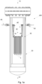
- FIG. 1a shows a cross section through an embodiment of a heating system 100 according to the invention.
- the heating system 100 comprises a structured body 10, arranged as an array of macroscopic structures 5. Each macroscopic structure 5 in the array is coated with a ceramic coating.
- the heating system 100 moreover comprises conductors 40, 40' connected to a power supply (not shown in the Figures) and to the structured body 10, viz. the array of macroscopic structures.
- the conductors 40, 40' are led through the wall of a pressure shell 20 housing the structured body and through insulating material 30 on the inner side of the pressure shell, via fittings 50.
- the conductors 40' are connected to the array of macroscopic structures 5 by conductor contact rails 41.
- the electrical power supply supplies a voltage of 26V and a current of 1200A. In another embodiment, the electrical power supply supplies a voltage of 5V and a current of 240A.
- the current is led through electrical conductors 40, 40' to conductor contact rails 41, and the current runs through the structured body 10 from one conductor contact rail 41, e.g. from the conductor contact rail seen to the left in Figure 1a , to the other conductor contact rail 41, e.g. the conductor contact rail seen to the right in Figure 1a .
- the current can be both alternating current, and e.g. run alternating in both directions, or direct current and run in any of the two directions.
- the macroscopic structures 5 are made of electrically conductive material. Especially preferred is the alloy kanthal consisting of aluminum, iron and chrome.
- the ceramic coating is e.g. an oxide, coated onto the structured body 5.
- the conductors 40, 40' are made in materials like iron, aluminum, nickel, copper or alloys thereof.
- a feed gas enters the heating system 100 from above as indicated by the arrow 11. Heated gas exits the heating system from the bottom thereof as indicated by the arrow 12.
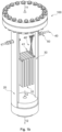
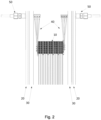
- Figure 1b shows the heating system 100 of Figure 1a with a part of the pressure shell 20 and heat insulation 30 layer removed and Figure 2 is an enlarged view of a part of the heating system 100.
- Figures 1b and 2 the connections between conductors 40' and conductor contact rails 41 are shown more clearly than in Figure 1a .
- the conductors 40 are led through the walls of the pressure shell in a fitting 50, and that the one conductor 40 is split up into three conductors 40' within the pressure shell.
- the number of conductors 40' may be any appropriate number, such as smaller than three or even larger than three.
- the conductors 40, 40' are led through the wall of a pressure shell 20 housing the structured body and through insulating material 30 on the inner side of the pressure shell, via fittings 50.
- Feed gas is inlet into the heating system 100 via an inlet in the upper side of the heating system 100 as shown by the arrow 11, and heated gas exits the heating system 100 via an outlet in the bottom of the heating system 100 as shown by the arrow 12.
- inert material (not shown in Figures 1a-2 ) is advantageously present between the lower side of the structured body 10 and the bottom of the pressure shell. Moreover, inert material is advantageously present between the outer sides of the structured body 10 of macroscopic structures 5 and the insulating material 30. Thus, one side of the insulating material 30 faces the inner side of the pressure shell 20 and the other side of the insulating material 30 faces the inert material.
- the inert materiel is e.g. ceramic material and may be in the form of pellets. The inert material assists in controlling the pressure drop across the heating system 100 and in controlling the flow of the gas through the heating system 100, so that the gas flows over the surfaces of the structured body 10.
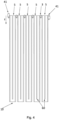
- Figures 3 and 4 show an embodiment of a structured body comprising an array of macroscopic structures as seen from above and from the side, respectively.
- Figure 3 shows a structured body 10 comprising an array of macroscopic structure 5 seen from above, viz. as seen from the arrow 11 in Figures 1a and 1b .
- the array has 6 rows, viz. 1a, 1b, 1c, 1d, 1e and 1f, of five macroscopic structures 5.
- the macroscopic structures 5 in each row are connected to its neighboring macroscopic structure (s) in the same row and the two outermost macroscopic structures in each row are connected to a conductor contact rail 41.
- the neighboring macroscopic structures 5 in a row of macroscopic structures are connected to each other by means of a connection piece 3.
- FIG 4 shows the structured body 10 having an array of macroscopic structures 5 of Figure 3 seen from the side. From Figure 4 , it can be seen that each macroscopic structure 5 extends longitudinally perpendicular to the cross section seen in Figure 3 . Each macroscopic structure 5 has a slit 60 cut into it along its longitudinal direction (see Figure 4 ). Therefore, when energized by the power source, the current enters the array of macroscopic structures 5 via a conductor contact rail 41, is led through the first macroscopic structure 5 downwards until the lower limit of the slit 60 and is subsequently led upwards towards a connection piece 3. The current is led via a corresponding zigzag path, downwards and upwards, through each macroscopic structure 5 in each row 1a-1f of macroscopic structures 5 in the array 10. This configuration advantageously increases the resistance over the structured body 10.
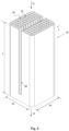
- FIG. 5 shows a structured body 10 according to the invention in a perspective view.
- the structured body 10 comprises a macroscopic structure that is coated with a ceramic coating.
- Within the structured body are channels 70 extending along the longitudinal direction (shown by the arrow indicate 'h' in Figure 5 ) of the macroscopic structure 5; the channels are defined by walls 75.
- the walls 75 define a number of parallel, square channels 70 when seen from the direction of flow as indicated by the arrow 12.
- the structured body 10 has a substantially square perimeter when seen from above, defined by the edge lengths e1 and e2. However, the perimeter could also be circular or another shape.
- the walls 75 of the structured body 10 are of extruded or 3D printed material coated with a ceramic coating, e.g. an oxide, which has been coated onto the macroscopic structure.
- a ceramic coating e.g. an oxide
- the ceramic coating is not shown.
- the ceramic coating is present on every wall within the structured body 10 over which the gas flow flows during operation and interacts with the heated surface of the structured.
- a slit 60 has been cut into the structured body 10.
- This slit 60 forces a current to take a zigzag route, in this instance downwards and subsequently upwards, within the macroscopic structure thereby increasing the current path and thus the resistance and consequently the heat dissipated within the macroscopic structure.
- the slit 60 within the macroscopic structure may be provided with embedded insulating material in order to ensure that no current flows in the transverse direction of the slit 60.
- the channels 70 in the structured body 10 are open in both ends.
- a feed gas flows through the unit, in the direction shown by arrows 11 and 12 in Figures 1a and 1b , and gets heated via contact with the walls 75 of the channels 70 and by heat radiation.
- the walls 75 of the channels 70 may e.g. have a thickness of 0.5 mm, and the ceramic coating coated onto the walls 75 may e.g. have a thickness of 0.1 mm.
- the arrows 11 and 12 indicate that the flow of the feed gas is down-flow, the opposite flow direction, viz. an up-flow, is also conceivable.
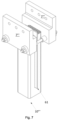
- Figure 6 shows the structured body 10 of Figures 1a and 1b in a perspective view and with connectors 7 attached.
- the connectors 7 each connect a part of the structured body 10 to a conductor 40.
- the conductors 40 are both connected to a power supply (not shown).
- Each of the connectors 7 are connected to an upper part of the structured body.
- an electrical current is led to the corresponding connector 7 via the conductor and runs through the structured body 10.
- the slit 60 hinders the current flow in a transverse direction (horizontal direction of Figure 6 ) throughout its lengths along the height h of the structured body 10.
- the current runs in a direction downwards as seen in Figure 6 in the part of the structured body along the slit 60, subsequently it runs transversely to the longitudinal direction below the slit 60 as seen in Figure 6 and finally the current runs upwards in the longitudinal direction of the structured body to the other connector 7.
- the connectors 7 in Figure 6 are mechanically fastened to the structured body by means of inter alia mechanical fastening means such as screws and bolts. However, additional or alternative fastening means are conceivable.
- the electrical power supply generates a voltage of 3V and a current of 400A.
- the connectors 7 are e.g. made in materials like iron, aluminum, nickel, copper or alloys thereof.
- the structured body 10 may be coated with a ceramic coating, such as an oxide.
- a ceramic coating such as an oxide.
- the parts of the structured body 10, which are connected to the connectors 7, should not be coated with an oxide. Instead, the macroscopic structure of the structured body should be exposed or connected directly to the connectors 7 in order to obtain a good electrical connection between the macroscopic structure and the connector.
- the feed gas entering into a heating system housing the structured body 10 would be able to cool the connectors 7 and the conductors 40.
- the feed gas entering into such a heating system could have a temperature of 200°C or 400°C and would thus keep the connectors 7 and conductors 40 from reaching temperatures much higher than this temperature.
- Figure 7 shows another embodiment of a structured body 10′′′ with connectors 7′′′.
- the structured body 10′′′ is e.g. the structured body as shown in Figure 6 .
- Each of the connectors 7′′′ has three holes at an upper side thereof for connection to conductors (not shown).
- a piece of electrically insulating material 61 is inside the slit 60 (see Figure 5 ) of the structured body 10′′′.
- the structured bodies shown in the figures are shown as having channels with a square cross section, as seen perpendicular to the z axis, any appropriate shape of the cross sections of the channels is conceivable.
- the channels of the structured body could alternatively be e.g. triangular, hexagonal, octagonal, or circular, where triangular, square, and hexagonal shapes are preferred.
- Figure 8 shows an embodiment of the process where a feedstock is provided by mixing syngas from a reforming reactor with a COz feedstock, where the COz is heated in a heating system 100 according to the invention.
- the heated COz is mixed with the syngas before or in an adiabatic post convertor 150. This produces a product gas more rich in CO than said first product gas.
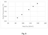
- Figure 9 shows experimental data from an experiment using an embodiment of the heating system according to the invention.
- the temperature of a pure COz feedstock at a flowrate of 50 Nl/h and approximately 5 barg was elevated from approximately 150°C inlet temperature to the temperature presented in Figure 9 as function of input power.
- Input power is shown as the transferred energy to the system relative to the surface area of the monolith, which is shown as heat flux on the x-axis of the figure.
- very high operating temperatures was achieved in the experiment, illustrating the high temperature capabilities of invention.
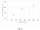
- Figure 10 shows experimental data from an experiment similar to the experiment of Figure 9 .
- Figure 10 shows another data series with COz heating at 2.5 brag and a higher heat input to achieve temperatures exceeding 1000°C.
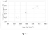
- Figure 11 shows experimental data from an experiment using an embodiment of the heating system according to the invention.
- the temperature of a pure N 2 feedstock at a flowrate of 250 Nl/h and 3.2 barg was elevated from approximately 150°C inlet temperature to the temperature presented in Figure 11 as function of input power.
- very high operating temperatures exceeding 1000°C was achieved in the experiment, illustrating the high temperature capabilities of invention.
- a case for synthesis gas module adjustment firstly using a traditional heating system for COz preheating as e.g. a tube heat exchanger placed in a fired heater of a chemical plant which gives a typical process gas preheating temperature of 650°C
- Table 1 shows the composition of syngas, which in this case is produced in a tubular reformer.
- a COz feed is preheated in a tube heat exchanger to 650°C.
- These streams are then mixed and sent an APOC where methanation/steam reforming and water gas shift reactions are taking place during an adiabatic reaction to produce a CO rich synthesis gas, in the given case increasing the CO yield by 36% from a fixed feedstock.
- the COz preheater can be done according to the heating system of the invention to achieve a higher temperature.
- the process according to Table 2 is achieved.
- Mixing and sending the COz and syngas to an APOC where methanation/steam reforming and water gas shift reactions are taking place during an adiabatic reaction produces a CO rich synthesis gas.
- the slip of CH 4 is decreased from 689 Nm 3 /h in Table 1 to 548 in Table 2.
Landscapes
- Chemical & Material Sciences (AREA)
- Organic Chemistry (AREA)
- Chemical Kinetics & Catalysis (AREA)
- Physics & Mathematics (AREA)
- Thermal Sciences (AREA)
- Physical Or Chemical Processes And Apparatus (AREA)
Claims (14)
- Système de chauffage pour chauffer un gaz d'alimentation, ledit système de chauffage comprenant :- un approvisionnement en gaz d'alimentation ;- un corps structuré agencé pour chauffer ledit gaz d'alimentation, ledit corps structuré comprenant une structure macroscopique de matériau électriquement conducteur ;- une coque étanche logeant ledit corps structuré, ladite coque étanche comprenant une entrée pour laisser entrer ledit gaz d'alimentation et une sortie pour laisser s'échapper du gaz chauffé, dans lequel ladite entrée est positionnée de sorte que ledit gaz d'alimentation pénètre dans ledit corps structuré dans une première extrémité dudit corps structuré et ledit gaz chauffé sorte dudit corps structuré par une seconde extrémité dudit corps structuré ;- une couche d'isolation thermique entre ledit corps structuré et ladite coque étanche ;- au moins deux conducteurs électriquement raccordés audit corps structuré et à une alimentation électrique placée à l'extérieur de ladite coque étanche, dans lequel ladite alimentation électrique est dimensionnée pour chauffer au moins une partie dudit corps structuré à une température d'au moins 400 °C en faisant passer un courant électrique à travers ladite structure macroscopique, dans lequel lesdits au moins deux conducteurs sont raccordés au corps structuré en une position sur le corps structuré plus proche de ladite première extrémité dudit corps structuré que de ladite seconde extrémité dudit corps structuré, et dans lequel le corps structuré est construit pour diriger un courant électrique pour qu'il circule d'un conducteur sensiblement à la seconde extrémité du corps structuré et retourne à un second desdits au moins deux conducteurs ; et,- une sortie pour le gaz chauffé.
- Système de chauffage selon la revendication 1, dans lequel ladite alimentation électrique est dimensionnée pour chauffer au moins une partie dudit corps structuré à une température d'au moins 700 °C, de préférence d'au moins 900 °C, plus préférentiellement d'au moins 1 000 °C.
- Système de chauffage selon l'une quelconque des revendications précédentes, dans lequel le gaz d'alimentation est sélectionné dans le groupe consistant en N2, H2, CO2, CH4, H2O, O2, et un mélange de ceux-ci.
- Système de chauffage selon l'une quelconque des revendications précédentes, dans lequel ladite structure macroscopique supporte un revêtement céramique.
- Système de chauffage selon l'une quelconque des revendications précédentes, dans lequel la résistivité du matériau électriquement conducteur est comprise entre 10-5 Ω•m et 10-7 Ω•m.
- Système de chauffage selon l'une quelconque des revendications précédentes, dans lequel lesdits au moins deux conducteurs sont guidés à travers la coque étanche dans un raccord de sorte que les au moins deux conducteurs soient électriquement isolés de la coque étanche.
- Système de chauffage selon l'une quelconque des revendications précédentes, dans lequel le matériau de la structure macroscopique est choisi comme un matériau agencé pour générer un flux thermique de 500 à 50000 W/m2 par chauffage par résistance du matériau.
- Système de chauffage selon l'une quelconque des revendications précédentes, dans lequel le corps structuré à l'intérieur dudit système de chauffage présente un rapport entre le diamètre équivalent de surface d'une section transversale horizontale à travers le corps structuré et la hauteur du corps structuré dans la plage de 0,1 à 2,0.
- Processus de chauffage d'un gaz d'alimentation dans un système de chauffage selon l'une quelconque des revendications précédentes ; ledit processus comprenant les étapes de :- mise sous pression dudit gaz d'alimentation,- fourniture dudit gaz d'alimentation sous pression au système de chauffage,- fourniture d'une puissance électrique par l'intermédiaire de conducteurs électriques raccordant une alimentation électrique placée à l'extérieur de ladite coque étanche audit corps structuré, permettant à un courant électrique de circuler à travers ledit matériau électriquement conducteur, chauffant ainsi au moins une partie du corps structuré,- chauffage du gaz d'alimentation sur le corps structuré et- évacuation d'un gaz chauffé du système de chauffage.
- Processus selon la revendication 9, dans lequel au moins une partie du corps structuré est chauffée à une température d'au moins 700 °C, de préférence d'au moins 900 °C, plus préférentiellement d'au moins 1 000 °C.
- Processus selon l'une quelconque des revendications 9-10, dans lequel le gaz chauffé provenant du système de chauffage est du CO2 sensiblement pur et est fourni à un post-convertisseur adiabatique conjointement avec un gaz de synthèse ; et dans ledit post-convertisseur adiabatique, le gaz chauffé réagit avec le gaz de synthèse pour fournir ainsi un second produit gazeux, ledit second produit gazeux étant un flux de gaz de synthèse riche en CO.
- Procédé de chauffage d'une matière première dans un système de chauffage selon l'une quelconque des revendications 1-8, d'une première condition de chauffage en régime permanent (A) à une seconde condition de chauffage en régime permanent (B) ou vice versa ; ledit procédé comprenant les étapes de :dans ladite première condition de chauffage en régime permanent (A) :- fourniture de ladite matière première au système de chauffage dans un premier flux total, et- fourniture d'une première puissance électrique par l'intermédiaire de conducteurs électriques raccordant une alimentation électrique placée à l'extérieur de ladite coque étanche audit corps structuré, permettant ainsi à un premier courant électrique de circuler à travers ledit matériau électriquement conducteur,chauffant ainsi au moins une partie du corps structuré à une première température à laquelle ladite matière première est chauffée sur ledit corps structuré dans lesdites premières conditions de chauffage en régime permanent (A) ; et ledit premier gaz chauffé est évacué du système de chauffage ;et, dans ladite seconde condition de chauffage en régime permanent (B) :- fourniture de ladite matière première au système de chauffage dans un second flux total,- fourniture d'une seconde puissance électrique par l'intermédiaire de conducteurs électriques raccordant une alimentation électrique placée à l'extérieur de ladite coque étanche audit corps structuré, permettant ainsi à un second courant électrique de circuler à travers ledit matériau électriquement conducteur,chauffant ainsi au moins une partie du corps structuré à une seconde température, à laquelle ladite matière première est chauffée sur ledit corps structuré dans lesdites secondes conditions de chauffage en régime permanent (B) ; et ledit second gaz chauffé est évacué du système de chauffage ;dans lequel ladite seconde puissance électrique est supérieure à ladite première puissance électrique ; et/ou ledit second flux total est supérieur audit premier flux total.
- Procédé selon la revendication 12, dans lequel le rapport entre le flux total de gaz d'alimentation dans ladite première condition de chauffage A et dans ladite seconde condition de chauffage B (A:B) est au moins de 1:10.
- Procédé selon l'une quelconque des revendications 12-13, dans lequel la température de sortie de gaz chauffé du corps structuré dans la condition de chauffage B est supérieure de 50 °C à 600 °C, par exemple supérieure de 100 °C à 500 °C, de préférence supérieure de 150 °C à 400 °C à la température de sortie de gaz chauffé du catalyseur structuré dans la condition de chauffage A.
Applications Claiming Priority (2)
| Application Number | Priority Date | Filing Date | Title |
|---|---|---|---|
| EP19213438 | 2019-12-04 | ||
| PCT/EP2020/084414 WO2021110809A1 (fr) | 2019-12-04 | 2020-12-03 | Dispositif de chauffage de gaz |
Publications (2)
| Publication Number | Publication Date |
|---|---|
| EP4069414A1 EP4069414A1 (fr) | 2022-10-12 |
| EP4069414B1 true EP4069414B1 (fr) | 2024-01-31 |
Family
ID=68771441
Family Applications (1)
| Application Number | Title | Priority Date | Filing Date |
|---|---|---|---|
| EP20816478.0A Active EP4069414B1 (fr) | 2019-12-04 | 2020-12-03 | Dispositif de chauffage de gaz |
Country Status (7)
| Country | Link |
|---|---|
| US (1) | US20230001368A1 (fr) |
| EP (1) | EP4069414B1 (fr) |
| KR (1) | KR20220104715A (fr) |
| CN (1) | CN114746173A (fr) |
| CA (1) | CA3163744A1 (fr) |
| FI (1) | FI4069414T3 (fr) |
| WO (1) | WO2021110809A1 (fr) |
Families Citing this family (1)
| Publication number | Priority date | Publication date | Assignee | Title |
|---|---|---|---|---|
| WO2024086300A1 (fr) * | 2022-10-19 | 2024-04-25 | Lydian Labs, Inc. | Systèmes et procédés de traitement catalytique chimique |
Family Cites Families (12)
| Publication number | Priority date | Publication date | Assignee | Title |
|---|---|---|---|---|
| JPH056120U (ja) * | 1991-07-04 | 1993-01-29 | カルソニツク株式会社 | 金属触媒装置 |
| US6841134B2 (en) * | 2001-01-12 | 2005-01-11 | Phoenix Solutions Co. | Electrically-heated chemical process reactor |
| DE10104601A1 (de) * | 2001-02-02 | 2002-08-14 | Xcellsis Gmbh | Reaktor für ein Brennstoffzellenssystem |
| CN202336644U (zh) * | 2011-11-28 | 2012-07-18 | 昆山市佰奥自动化设备科技有限公司 | 太阳能电池片串焊设备 |
| WO2013135710A2 (fr) * | 2012-03-13 | 2013-09-19 | Bayer Intellectual Property Gmbh | Procédé pour la réalisation d'une réaction rwgs dans un réacteur à faisceau tubulaire |
| DE102015110120A1 (de) * | 2015-06-24 | 2016-12-29 | Thyssenkrupp Ag | Optimierung des Wärmehaushalts in Reformern durch Einsatz von metallischen Katalysatorträgern |
| DE102016224711B4 (de) * | 2016-12-12 | 2019-08-01 | Continental Automotive Gmbh | Verfahren zum Betrieb eines elektrisch beheizbaren Katalysators |
| WO2019110267A1 (fr) | 2017-12-08 | 2019-06-13 | Haldor Topsøe A/S | Procédé et système de production de gaz de synthèse |
| US11649164B2 (en) * | 2017-12-08 | 2023-05-16 | Haldor Topsøe A/S | Plant and process for producing synthesis gas |
| US20200406212A1 (en) * | 2017-12-08 | 2020-12-31 | Haldor Topsøe A/S | System and process for synthesis gas production |
| EA202092761A1 (ru) * | 2018-05-31 | 2021-04-23 | Хальдор Топсёэ А/С | Эндотермические реакции с нагревом сопротивлением |
| EP3574991A1 (fr) * | 2018-05-31 | 2019-12-04 | Haldor Topsøe A/S | Reformage à la vapeur chauffée par un chauffage à résistance |
-
2020
- 2020-12-03 CA CA3163744A patent/CA3163744A1/fr active Pending
- 2020-12-03 KR KR1020227017650A patent/KR20220104715A/ko active Search and Examination
- 2020-12-03 US US17/782,341 patent/US20230001368A1/en active Pending
- 2020-12-03 FI FIEP20816478.0T patent/FI4069414T3/fi active
- 2020-12-03 EP EP20816478.0A patent/EP4069414B1/fr active Active
- 2020-12-03 CN CN202080083333.9A patent/CN114746173A/zh active Pending
- 2020-12-03 WO PCT/EP2020/084414 patent/WO2021110809A1/fr unknown
Also Published As
| Publication number | Publication date |
|---|---|
| CA3163744A1 (fr) | 2021-06-10 |
| FI4069414T3 (fi) | 2024-03-01 |
| KR20220104715A (ko) | 2022-07-26 |
| CN114746173A (zh) | 2022-07-12 |
| WO2021110809A1 (fr) | 2021-06-10 |
| EP4069414A1 (fr) | 2022-10-12 |
| US20230001368A1 (en) | 2023-01-05 |
Similar Documents
| Publication | Publication Date | Title |
|---|---|---|
| US20220242727A1 (en) | On demand hydrogen from ammonia | |
| KR20210014677A (ko) | 저항 가열에 의해 가열된 스팀 개질 | |
| US20220395805A1 (en) | Electric steam cracker | |
| US20220298015A1 (en) | On demand synthesis gas from methanol | |
| EP4069414B1 (fr) | Dispositif de chauffage de gaz | |
| US20220371885A1 (en) | On demand hydrogen from methanol | |
| US20220363537A1 (en) | Synthesis gas on demand | |
| US20220259056A1 (en) | Cyanide on demand | |
| EP4037821B1 (fr) | Navire ou installation de reformage en mer | |
| WO2023274938A1 (fr) | Corps structuré pour chauffer un gaz |
Legal Events
| Date | Code | Title | Description |
|---|---|---|---|
| STAA | Information on the status of an ep patent application or granted ep patent |
Free format text: STATUS: UNKNOWN |
|
| STAA | Information on the status of an ep patent application or granted ep patent |
Free format text: STATUS: THE INTERNATIONAL PUBLICATION HAS BEEN MADE |
|
| PUAI | Public reference made under article 153(3) epc to a published international application that has entered the european phase |
Free format text: ORIGINAL CODE: 0009012 |
|
| STAA | Information on the status of an ep patent application or granted ep patent |
Free format text: STATUS: REQUEST FOR EXAMINATION WAS MADE |
|
| 17P | Request for examination filed |
Effective date: 20220530 |
|
| AK | Designated contracting states |
Kind code of ref document: A1 Designated state(s): AL AT BE BG CH CY CZ DE DK EE ES FI FR GB GR HR HU IE IS IT LI LT LU LV MC MK MT NL NO PL PT RO RS SE SI SK SM TR |
|
| DAV | Request for validation of the european patent (deleted) | ||
| DAX | Request for extension of the european patent (deleted) | ||
| GRAP | Despatch of communication of intention to grant a patent |
Free format text: ORIGINAL CODE: EPIDOSNIGR1 |
|
| STAA | Information on the status of an ep patent application or granted ep patent |
Free format text: STATUS: GRANT OF PATENT IS INTENDED |
|
| INTG | Intention to grant announced |
Effective date: 20231010 |
|
| GRAS | Grant fee paid |
Free format text: ORIGINAL CODE: EPIDOSNIGR3 |
|
| P01 | Opt-out of the competence of the unified patent court (upc) registered |
Effective date: 20231107 |
|
| GRAA | (expected) grant |
Free format text: ORIGINAL CODE: 0009210 |
|
| STAA | Information on the status of an ep patent application or granted ep patent |
Free format text: STATUS: THE PATENT HAS BEEN GRANTED |
|
| AK | Designated contracting states |
Kind code of ref document: B1 Designated state(s): AL AT BE BG CH CY CZ DE DK EE ES FI FR GB GR HR HU IE IS IT LI LT LU LV MC MK MT NL NO PL PT RO RS SE SI SK SM TR |
|
| REG | Reference to a national code |
Ref country code: GB Ref legal event code: FG4D Ref country code: CH Ref legal event code: EP |
|
| REG | Reference to a national code |
Ref country code: DE Ref legal event code: R096 Ref document number: 602020025055 Country of ref document: DE |
|
| REG | Reference to a national code |
Ref country code: NL Ref legal event code: FP Ref country code: IE Ref legal event code: FG4D |
|
| REG | Reference to a national code |
Ref country code: SE Ref legal event code: TRGR |
|
| REG | Reference to a national code |
Ref country code: LT Ref legal event code: MG9D |