EP4068948B1 - Harvesting head for forestry and a method for determining a thickness of a tree trunk in a harvesting head for forestry - Google Patents
Harvesting head for forestry and a method for determining a thickness of a tree trunk in a harvesting head for forestry Download PDFInfo
- Publication number
- EP4068948B1 EP4068948B1 EP20817338.5A EP20817338A EP4068948B1 EP 4068948 B1 EP4068948 B1 EP 4068948B1 EP 20817338 A EP20817338 A EP 20817338A EP 4068948 B1 EP4068948 B1 EP 4068948B1
- Authority
- EP
- European Patent Office
- Prior art keywords
- tree trunk
- limbing
- harvesting head
- measuring
- thickness
- Prior art date
- Legal status (The legal status is an assumption and is not a legal conclusion. Google has not performed a legal analysis and makes no representation as to the accuracy of the status listed.)
- Active
Links
Images



Classifications
-
- A—HUMAN NECESSITIES
- A01—AGRICULTURE; FORESTRY; ANIMAL HUSBANDRY; HUNTING; TRAPPING; FISHING
- A01G—HORTICULTURE; CULTIVATION OF VEGETABLES, FLOWERS, RICE, FRUIT, VINES, HOPS OR SEAWEED; FORESTRY; WATERING
- A01G23/00—Forestry
- A01G23/02—Transplanting, uprooting, felling or delimbing trees
- A01G23/08—Felling trees
- A01G23/083—Feller-delimbers
-
- A—HUMAN NECESSITIES
- A01—AGRICULTURE; FORESTRY; ANIMAL HUSBANDRY; HUNTING; TRAPPING; FISHING
- A01G—HORTICULTURE; CULTIVATION OF VEGETABLES, FLOWERS, RICE, FRUIT, VINES, HOPS OR SEAWEED; FORESTRY; WATERING
- A01G23/00—Forestry
- A01G23/02—Transplanting, uprooting, felling or delimbing trees
- A01G23/095—Delimbers
-
- A—HUMAN NECESSITIES
- A01—AGRICULTURE; FORESTRY; ANIMAL HUSBANDRY; HUNTING; TRAPPING; FISHING
- A01G—HORTICULTURE; CULTIVATION OF VEGETABLES, FLOWERS, RICE, FRUIT, VINES, HOPS OR SEAWEED; FORESTRY; WATERING
- A01G3/00—Cutting implements specially adapted for horticultural purposes; Delimbing standing trees
- A01G3/08—Other tools for pruning, branching or delimbing standing trees
- A01G3/085—Motor-driven saws for pruning or branching
-
- G—PHYSICS
- G01—MEASURING; TESTING
- G01B—MEASURING LENGTH, THICKNESS OR SIMILAR LINEAR DIMENSIONS; MEASURING ANGLES; MEASURING AREAS; MEASURING IRREGULARITIES OF SURFACES OR CONTOURS
- G01B11/00—Measuring arrangements characterised by the use of optical techniques
- G01B11/02—Measuring arrangements characterised by the use of optical techniques for measuring length, width or thickness
- G01B11/04—Measuring arrangements characterised by the use of optical techniques for measuring length, width or thickness specially adapted for measuring length or width of objects while moving
- G01B11/046—Measuring arrangements characterised by the use of optical techniques for measuring length, width or thickness specially adapted for measuring length or width of objects while moving for measuring width
-
- G—PHYSICS
- G01—MEASURING; TESTING
- G01B—MEASURING LENGTH, THICKNESS OR SIMILAR LINEAR DIMENSIONS; MEASURING ANGLES; MEASURING AREAS; MEASURING IRREGULARITIES OF SURFACES OR CONTOURS
- G01B21/00—Measuring arrangements or details thereof, where the measuring technique is not covered by the other groups of this subclass, unspecified or not relevant
- G01B21/02—Measuring arrangements or details thereof, where the measuring technique is not covered by the other groups of this subclass, unspecified or not relevant for measuring length, width, or thickness
- G01B21/06—Measuring arrangements or details thereof, where the measuring technique is not covered by the other groups of this subclass, unspecified or not relevant for measuring length, width, or thickness specially adapted for measuring length or width of objects while moving
-
- G—PHYSICS
- G01—MEASURING; TESTING
- G01B—MEASURING LENGTH, THICKNESS OR SIMILAR LINEAR DIMENSIONS; MEASURING ANGLES; MEASURING AREAS; MEASURING IRREGULARITIES OF SURFACES OR CONTOURS
- G01B5/00—Measuring arrangements characterised by the use of mechanical techniques
- G01B5/0035—Measuring of dimensions of trees
-
- G—PHYSICS
- G01—MEASURING; TESTING
- G01B—MEASURING LENGTH, THICKNESS OR SIMILAR LINEAR DIMENSIONS; MEASURING ANGLES; MEASURING AREAS; MEASURING IRREGULARITIES OF SURFACES OR CONTOURS
- G01B11/00—Measuring arrangements characterised by the use of optical techniques
- G01B11/08—Measuring arrangements characterised by the use of optical techniques for measuring diameters
-
- G—PHYSICS
- G01—MEASURING; TESTING
- G01B—MEASURING LENGTH, THICKNESS OR SIMILAR LINEAR DIMENSIONS; MEASURING ANGLES; MEASURING AREAS; MEASURING IRREGULARITIES OF SURFACES OR CONTOURS
- G01B5/00—Measuring arrangements characterised by the use of mechanical techniques
- G01B5/08—Measuring arrangements characterised by the use of mechanical techniques for measuring diameters
- G01B5/12—Measuring arrangements characterised by the use of mechanical techniques for measuring diameters internal diameters
Definitions
- the present invention relates to a harvesting head for forestry and a method of determining a thickness of a tree trunk in a harvesting head.
- a harvesting head usually consists of a rigid frame to which there is attached a pair of front limbing knives, a pair of feeding rollers, a chain saw and sometimes one or two back limbing knives situated between the pair of feeding rollers and the chain saw.
- a harvesting head functions as such that it grips a tree by its trunk close to the ground. It then cuts through the trunk and fells the tree. The tree is then fed through the harvesting head, which limbs the tree as it passes therethrough. After feeding through certain lengths of the tree the fed-through parts are cut off, after which the tree is continued to be fed through. When the tree's trunk becomes too thin, the tree is let go off.
- harvesting heads are disclosed in WO00/15026A1 , WO2019/226088A1 , WO2009/157864A1 and WO2006/092469A1 .
- the limbing knives, the feeding rollers as well as the chain saw are all pivotally movable.
- the chain saw such that it can move against the tree trunk and saw it through.
- the feeding rollers such that they can grip the tree trunk and feed it through the harvesting head by rolling.
- the limbing knives such that they can enclose the trunk and press it against a gliding surface of the harvesting head.
- a gliding surface is a surface on the harvesting head's frame against which a tree trunk glides when it is fed through the harvesting head.
- the thickness of a fed through tree trunk is typically determined by measuring the position of a limbing knife or a feeding roller and relating its position to the frame of the harvesting head, typically the gliding surface. Since the tree trunk is pressed against the frame by either a limbing knife or a feeding roller, the position of the limbing knife or feeding roller will be related to the thickness of the fed through trunk.
- a method for determining a thickness of a tree trunk in a harvesting head for forestry comprising
- a tree trunk surface follower is a device which is arranged to follow the surface of a tree trunk held in a harvesting head, following the movement of the tree trunk surface while the tree trunk is fed through the harvesting head.
- the tree trunk surface follower may abut the tree trunk surface but does not need to.
- the tree trunk surface follower is placed as close to the tree trunk pressing device as possible, in the feeding direction of the tree trunk, such that the deviation of the tree trunk is determined as close to the measured thickness as possible.
- the dependence of the position of the tree trunk surface follower on the thickness of a tree trunk can be adjusted for.
- Themethod comprises determining a thickness of a tree trunk in a harvesting head for forestry, said harvesting head comprising
- the harvesting head further comprises a proximity sensor, and measuring the position of the tree trunk surface follower is done with the proximity sensor.
- the proximity sensor is a magneto-inductive sensor.
- the tree trunk surface follower is pressed against at least a portion of the half of the circumference of the tree trunk which is closest to the reference surface. In this manner the tree trunk surface follower follows the position of the tree trunk's surface, following the part of the tree trunk which is closest to the reference surface. This assures that the position of the tree trunk surface follower will be related to the deviation of the tree trunk from the reference surface.
- a method for determining a volume of a tree trunk in a harvesting head by determining a length and several thicknesses of the tree trunk. The determined thicknesses being spaced at a certain length interval. The volume being calculated based on the determined length and thicknesses. The thicknesses being determined according to the previously disclosed method. In this manner a more accurate volume of a tree trunk can be determined. The volume of the tree trunk will be adjusted for any inaccuracies coming from deviations from the reference surface of the tree trunk during volume determining.
- a harvesting head for forestry comprising a thickness measuring arrangement for measuring a measured thickness of a tree trunk, said thickness measuring arrangement comprising a tree trunk pressing device, for pressing said tree trunk in a direction towards a reference surface of the harvesting head , and a first measuring sensor arranged to measure the position of said tree trunk pressing device relative to said reference surface,
- the second measuring sensor is a magneto-inductive measuring sensor.
- the limbing member is arranged on a front side of a front plate of the harvesting head, and the second measuring sensor is arranged on a back side of the front plate, the back side being opposite to the front side
- the second measuring sensor comprises a first portion and a second portion, and the first portion is arranged on the front plate and the second portion is arranged on the limbing member.
- the front plate comprises a slit extending through the front plate from the front side to the back side,
- the tree trunk surface follower is arranged to follow at least a portion of the half of the circumference of the tree trunk which is closest to the reference surface.
- This embodiment has the advantage of assuring that the tree trunk surface follower follows the position of the tree trunk surface, following the part of the tree trunk which is closest to the reference surface, which in its turn assures that the position of the tree trunk surface follower is related to the deviation of the tree trunk from the reference surface.
- the tree trunk surface follower may be pressed towards the tree trunk by a compression spring, a torsion spring or a hydraulic piston.
- the tree trunk pressing device may comprise at least one limbing knife.
- the tree trunk surface follower may be linearly guided.
- the front limbing knives 3, 4 are used to limb a tree trunk 17 as well as to determine a thickness of it.
- the back limbing knives 7, 8 are also pivotally movable in a plane perpendicular to the feeding direction A of the tree trunk 17 and used to enclose a tree trunk 17 and press it in a direction towards the gliding surface 15.
- the limbing knives 3, 4, 7, 8 have the form of curved knives with the sharp end on the front side.
- An enclosed tree trunk 17 will have its limbs cut off by the limbing knives 3, 4, 7, 8 when fed through the harvesting head 1 in feeding direction A.
- the chain saw 10 is used to cut off limbed pieces of a tree trunk 17.
- the chain saw 10 is held inside a cover 9 and is pivotally movable in a plane perpendicular to the feeding direction A of the tree trunk 17.
- the tree trunk 17 is cut by moving the chain saw 10 through it.
- the limbing member 11 is curved. By this is meant that a portion of the limbing member 11 arranged to be closest to a tree trunk 17 fed through the harvesting head has a curved shape. This could be a sharp edge, which is comprised by the limbing member, configured to delimb a portion of the circumference of the tree trunk 17.
- a curved shape could be a continuous curve.
- a curved shape could be a combination of two or more straight lines or surfaces arranged at an angle relative each other.
- a curved shape could be a combination of a continuous curve and one or more straight lines or surfaces arranged at an angle relative each other.
- the limbing member is curved such that it is concave towards the tree trunk.
- the thickness T 1 , T 2 is determined by a thickness determining arrangement 18, which comprises the pair of front limbing knives 3, 4 and rotary encoders 19.
- the rotary encoders 19 are arranged to measure the angular position of the front limbing knives 3, 4.
- the angular position of the limbing knives 3, 4 is related to the gliding surface 15, and thereby a thickness of a tree trunk 17, through a conversion table which relates different angular positions of the front limbing knives 3, 4 to different thicknesses.
- the position of the limbing knives 3, 4, in relation to the gliding surface 15 will be directly related to the thickness of a tree trunk 17.
- the measured thickness T 1 , T 2 will be wrong.
- a common cause of measurement error is a deviation of the tree trunk 17 from the gliding surface 15. Such a deviation may occur if the tree trunk 17 is curved or if its surface is uneven, for example from a poorly cut off limb.
- FIG 4 shows a cross sectional view of the harvesting head 1 holding a tree trunk 17 from Figure 2 .
- the tree trunk 17 has an uneven surface.
- This unevenness has produced a deviation D of the tree trunk 17 from the gliding surface 15.
- This deviation D is what differs a measured thickness T from a corrected thickness T c .
- the corrected thickness T c being the measured thickness T corrected for the deviation D.
- the deviation is determined by a deviation measuring arrangement 20, which comprises the limbing member 11, a linear contact sensor 21, a rotational joint 25 and a torsion spring situated in the rotational joint 25.
- the limbing member 11 is pivotally coupled to the harvesting head 1 by rotational joint 25.
- the torsion spring presses the limbing member 11 towards the tree trunk 17 in a direction E by rotating the limbing member 11 in direction F.
- the linear contact sensor 21 is mechanically coupled to the limbing member 11 by connection 23.
- the linear contact sensor 21 measures the position of the limbing member 11. By measuring the position of the limbing member 11 it is possible to measure the deviation D. Since the limbing member 11 follows the surface of the tree trunk 17 its position can be related to the position of the surface which it follows. If the surface which the tree trunk surface follower follows is on the half of the circumference of the tree trunk 17 closest to the gliding surface 15, i.e.
- the length measuring wheel 13 is pivotally coupled to the harvesting head 1 such that it moves in direction G, when pressed towards the surface of the tree trunk 17.
- the length measuring wheel 13 is pressed towards the surface of the tree trunk 17 by means of a hydraulic cylinder 27.
- Figure 5a and 5b show an alternative limbing member 11' to the one shown in Figures 1 through 4 .
- the limbing member 11' is linearly guided and pressed towards the tree trunk 17 in direction H by compression springs 29.
- the alternative limbing member's 11' position relative to the gliding surface 15 may be measured by a linear contact sensor mechanically coupled to the limbing member 11' or by a contact free linear sensor.
- the sensor 22 comprises a first portion 22a and a second portion 22b.
- the first portion 22a is arranged on the front plate 12, on the back side of the front plate.
- the second portion 22b is arranged on the limbing member 11.
- the front plate 12 comprises a slit 23.
- the slit 23 extends through the front plate 12 form the front side to the back side.
- the second portion of the sensor 22b is arranged in the slit 23.
- a corrected thickness T c of the tree trunk 17 is determined by determining a measured thickness T and a deviation D of the tree trunk 17 and calculating a corrected thickness T c based on the deviation D and the measured thickness T.
- the deviation D is determined by measuring the position of the limbing member 11, with linear contact sensor 21, and relating its position to the gliding surface 15.
- the position of the limbing member 11 being related to the gliding surface 15, and thereby a deviation D, through a conversion table which relates different positions of the limbing member 11 to different deviations D of a tree trunk 17 held in the harvesting head 1.
- the corrected thickness T c is calculated by subtracting the deviation D from the measured thickness T.
- the tree trunk pressing device may be any other limbing knife 3, 4, 7, 8. It does not need to be a pair of limbing knives, it may be more than a pair or just one knife. It may also be one or several feed rollers 5, 6.
- the tree trunk pressing device may be a device separate from a limbing knife.
- the tree trunk pressing device may be anything as long as it presses the tree trunk in a direction towards a reference surface.
- a tree trunk surface follower may instead of a limbing member 11, 11' be a measuring wheel 13.
- the tree trunk surface follower may be a device separate from a limbing member or length measuring wheel.
- a reference surface does not need to be a gliding surface, it could be a surface of any size, situated anywhere on the harvesting head as long as the tree trunk is pressed in a direction towards it and the position of a tree trunk pressing device and the position of a tree trunk surface follower is related to it.
- Several thicknesses of the tree trunk may be determined at several points on the tree trunk 17 as it is fed through the harvesting head 1, the points separated by a certain length interval, the interval may be 10 centimeters.
- the linear contact sensor 21 mechanically coupled to the limbing member 11 by connection 23, it is possible to use a contact free linear sensor, which would not need the connection 23. It is also possible to use an angle sensor positioned inside joint 25, the angle sensor could be a rotary encoder or an analog angle sensor. If the tree trunk surface follower is a measuring wheel 13, its position relative to the gliding surface 15 could be measured by a linear contact sensor coupled to the measuring wheel 13. It could also be measured by a contact free linear sensor or by an angle sensor such as a rotary encoder or analog angle sensor.
- a few alternatives to a tree trunk surface follower and devices pressing it towards a tree trunk surface has been disclosed.
- the devices can be combined with whichever tree trunk surface follower.
- a measuring wheel could also be pressed towards the tree trunk surface by a compression spring or a torsion spring.
- the deviation may also be determined by not only relating the position of the limbing member 11 to the gliding surface 15, but also by relating the position of the limbing member 11 to the measured thickness T of the tree trunk 17.
- the position of the limbing member 11 being related to the gliding surface 15, and thereby a deviation D, through a conversion table which relates different positions of the limbing member 11 as well as different measured thicknesses T to different deviations D of a tree trunk 17 held in the harvesting head 1.
Landscapes
- Life Sciences & Earth Sciences (AREA)
- Biodiversity & Conservation Biology (AREA)
- Ecology (AREA)
- Forests & Forestry (AREA)
- Environmental Sciences (AREA)
- Physics & Mathematics (AREA)
- General Physics & Mathematics (AREA)
- Botany (AREA)
- A Measuring Device Byusing Mechanical Method (AREA)
- Measurement Of Length, Angles, Or The Like Using Electric Or Magnetic Means (AREA)
- Length Measuring Devices With Unspecified Measuring Means (AREA)
- Measurement Of The Respiration, Hearing Ability, Form, And Blood Characteristics Of Living Organisms (AREA)
Description
- The present invention relates to a harvesting head for forestry and a method of determining a thickness of a tree trunk in a harvesting head.
- Harvesting heads are used in forestry to cut down trees, limb them, cut the trunk into smaller pieces and while doing this also determine the size of the trees. The sizes that are determined are the length and thickness of the trees' trunks.
- A harvesting head usually consists of a rigid frame to which there is attached a pair of front limbing knives, a pair of feeding rollers, a chain saw and sometimes one or two back limbing knives situated between the pair of feeding rollers and the chain saw.
- A harvesting head functions as such that it grips a tree by its trunk close to the ground. It then cuts through the trunk and fells the tree. The tree is then fed through the harvesting head, which limbs the tree as it passes therethrough. After feeding through certain lengths of the tree the fed-through parts are cut off, after which the tree is continued to be fed through. When the tree's trunk becomes too thin, the tree is let go off.
- Examples of harvesting heads are disclosed in
WO00/15026A1 WO2019/226088A1 ,WO2009/157864A1 andWO2006/092469A1 . - The limbing knives, the feeding rollers as well as the chain saw are all pivotally movable. The chain saw such that it can move against the tree trunk and saw it through. The feeding rollers such that they can grip the tree trunk and feed it through the harvesting head by rolling. The limbing knives such that they can enclose the trunk and press it against a gliding surface of the harvesting head. A gliding surface is a surface on the harvesting head's frame against which a tree trunk glides when it is fed through the harvesting head.
- The length of a tree trunk is measured continuously as a trunk is fed through the harvesting head. The thickness of a tree trunk is determined at several points with a certain length interval. The thickness and length of a tree trunk is used to calculate the volume of the harvested tree.
- The thickness of a fed through tree trunk is typically determined by measuring the position of a limbing knife or a feeding roller and relating its position to the frame of the harvesting head, typically the gliding surface. Since the tree trunk is pressed against the frame by either a limbing knife or a feeding roller, the position of the limbing knife or feeding roller will be related to the thickness of the fed through trunk.
- Although this method may have an acceptable accuracy for now, it is far from perfect and the determined thickness is too often wrong.
- It is an object of the present disclosure to present a method for determining a thickness of a tree trunk in a harvesting head for forestry with increased accuracy. It is also an object of the present disclosure to present a harvesting head for forestry which can determine a thickness of a tree trunk with increased accuracy.
- The invention is defined by the appended independent claims.
- According to an aspect of the invention there is provided a method for determining a thickness of a tree trunk in a harvesting head for forestry, said harvesting head comprising
- a tree trunk pressing device, and
- a tree trunk surface follower,
- wherein the tree trunk surface follower is a limbing member, and wherein the limbing member is curved,
- said method comprising
- pressing the tree trunk, with said tree trunk pressing device, in a direction towards a reference surface of the harvesting head and
- determining a measured thickness by measuring the position of the tree trunk pressing device and relating said position to said reference surface,
- said method further comprising the steps of
- determining a deviation of the tree trunk from said reference surface by measuring a position of the tree trunk surface follower and relating said position of the tree trunk surface follower to said reference surface, and
- calculating a corrected thickness of the tree trunk based on said measured thickness and said deviation,
- wherein determining the deviation further comprises relating said position of the tree trunk surface follower to said measured thickness. In this manner a thickness of a tree trunk can be determined which is corrected for any deviation of the tree trunk from the reference surface. The accuracy of the determined thickness will be much improved and thereby also the accuracy of the calculated volume of the harvested trees. By being able to adjust for a deviation of a tree trunk from a reference surface the tree trunk does no longer need to be pressed against the reference surface at all times, instead a deviation can be allowed. Thus, the pressing power of the tree trunk pressing device can be reduced and the friction of the tree against the harvesting head will be reduced as a result. This will lead to less power consumption and a faster limbing process in the harvesting head.
- A tree trunk surface follower is a device which is arranged to follow the surface of a tree trunk held in a harvesting head, following the movement of the tree trunk surface while the tree trunk is fed through the harvesting head. The tree trunk surface follower may abut the tree trunk surface but does not need to. Ideally, the tree trunk surface follower is placed as close to the tree trunk pressing device as possible, in the feeding direction of the tree trunk, such that the deviation of the tree trunk is determined as close to the measured thickness as possible.
- By determining the deviation by measuring the position of a tree trunk surface follower and relating its position to both the reference surface and the measured thickness, the dependence of the position of the tree trunk surface follower on the thickness of a tree trunk can be adjusted for.
- Themethod comprises determining a thickness of a tree trunk in a harvesting head for forestry, said harvesting head comprising
- a tree trunk pressing device, and
- a curved limbing member,
- said method comprising
- pressing the tree trunk, with said tree trunk pressing device, in a direction towards a reference surface of the harvesting head and
- determining a measured thickness by measuring the position of the tree trunk pressing device and relating said position to said reference surface,
- said method further comprising the steps of
- measuring a position of the limbing member,
- determining a deviation of the tree trunk from said reference surface as a function of said position of the limbing member, a curvature of the limbing member and said measured thickness, and
- calculating a corrected thickness of the tree trunk based on said measured thickness and said deviation.
- The harvesting head further comprises a proximity sensor, and measuring the position of the tree trunk surface follower is done with the proximity sensor.
- According to one embodiment the proximity sensor is a magneto-inductive sensor.
- According to one embodiment of the disclosure the tree trunk surface follower is pressed against at least a portion of the half of the circumference of the tree trunk which is closest to the reference surface. In this manner the tree trunk surface follower follows the position of the tree trunk's surface, following the part of the tree trunk which is closest to the reference surface. This assures that the position of the tree trunk surface follower will be related to the deviation of the tree trunk from the reference surface.
- According to another aspect of the present disclosure there is provided a method for determining a volume of a tree trunk in a harvesting head by determining a length and several thicknesses of the tree trunk. The determined thicknesses being spaced at a certain length interval. The volume being calculated based on the determined length and thicknesses. The thicknesses being determined according to the previously disclosed method. In this manner a more accurate volume of a tree trunk can be determined. The volume of the tree trunk will be adjusted for any inaccuracies coming from deviations from the reference surface of the tree trunk during volume determining.
- According to another aspect of the invention there is provided a harvesting head for forestry, comprising a thickness measuring arrangement for measuring a measured thickness of a tree trunk, said thickness measuring arrangement comprising a tree trunk pressing device, for pressing said tree trunk in a direction towards a reference surface of the harvesting head , and a first measuring sensor arranged to measure the position of said tree trunk pressing device relative to said reference surface,
- said harvesting head further comprising
- a deviation measuring arrangement, for measuring a deviation of said tree trunk from said reference surface,
- said deviation measuring arrangement comprising a tree trunk surface follower and a second measuring sensor arranged to measure the position of said tree trunk surface follower,
- wherein the tree trunk surface follower is a limbing member, and
- wherein the second measuring sensor is a proximity sensor. An advantage of this embodiment is that it can determine a thickness of a tree trunk which is corrected for a deviation of the tree trunk from the reference surface.
- According to one embodiment the second measuring sensor is a magneto-inductive measuring sensor.
- The limbing member is arranged on a front side of a front plate of the harvesting head, and the second measuring sensor is arranged on a back side of the front plate, the back side being opposite to the front side
- The second measuring sensor comprises a first portion and a second portion, and the first portion is arranged on the front plate and the second portion is arranged on the limbing member.
- According to one embodiment the front plate comprises a slit extending through the front plate from the front side to the back side,
- wherein the first portion of the second measuring sensor is arranged on the back side of the front plate, and
- the second portion of the second measuring sensor is arranged in the slit.
- In another embodiment of the present disclosure the tree trunk surface follower is arranged to follow at least a portion of the half of the circumference of the tree trunk which is closest to the reference surface. This embodiment has the advantage of assuring that the tree trunk surface follower follows the position of the tree trunk surface, following the part of the tree trunk which is closest to the reference surface, which in its turn assures that the position of the tree trunk surface follower is related to the deviation of the tree trunk from the reference surface.
- The tree trunk surface follower may be pressed towards the tree trunk by a compression spring, a torsion spring or a hydraulic piston.
- The tree trunk pressing device may comprise at least one limbing knife.
- The tree trunk surface follower may be pivotally coupled to the harvesting head.
- The tree trunk surface follower may be linearly guided.
- The second measuring sensor may be a contact free linear sensor.
- These and other aspects of the invention will be apparent from and elucidated with reference to the claims and the embodiments described hereinafter.
-
-
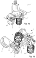
Figure 1a is a perspective view and illustrates a harvesting head for forestry. -
Figure 1b is a perspective view from below illustrating the same harvesting head as inFigure 1a . -
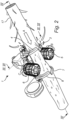
Figure 2 is a perspective view from below illustrating the same harvesting head as inFigures 1a and 1b holding a tree trunk and feeding it through itself. -
Figure 3 is a cross sectional view, along III inFigure 2 , illustrating how tree trunks of different thicknesses is held by the harvesting head. -
Figure 4 is a cross sectional view, along IV inFigure 2 , illustrating a tree trunk being fed through the harvesting head. -
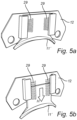
Figure 5a is a perspective view illustrating an alternative limbing member, showing it in a retracted state -
Figure 5b is a perspective view illustrating the same limbing member as inFigure 5a , showing it in a protracted state. -
Figure 6 is a cross sectional view, along VI inFigure 2 , illustrating how tree trunks of different thicknesses affect the position of a limbing member. - In
Figure 1a and Figure 1b aharvesting head 1 for forestry is shown. Theharvesting head 1 comprises a tree trunk pressing device, in this case a pair offront limbing knives member 11, and a reference surface, in this case a glidingsurface 15. Theharvesting head 1 further comprises a pair of feedingrollers knives chain saw 10 and alength measuring wheel 13. - In
Figure 2 thesame harvesting head 1 is shown while holding atree trunk 17 and feeding it through itself. Thefeeding rollers tree trunk 17 and feed it through theharvesting head 1. Therollers tree trunk 17 between them. By spinning therollers tree trunk 17 will be moved through theharvesting head 1 in a feeding direction A. The limbingknives tree trunk 17 and are used to enclose atree trunk 17 and press it in a direction towards the glidingsurface 15. Thefront limbing knives tree trunk 17 as well as to determine a thickness of it. Theback limbing knives tree trunk 17 and used to enclose atree trunk 17 and press it in a direction towards the glidingsurface 15. The limbingknives enclosed tree trunk 17 will have its limbs cut off by the limbingknives harvesting head 1 in feeding direction A. The chain saw 10 is used to cut off limbed pieces of atree trunk 17. The chain saw 10 is held inside acover 9 and is pivotally movable in a plane perpendicular to the feeding direction A of thetree trunk 17. Thetree trunk 17 is cut by moving the chain saw 10 through it. - The limbing
member 11 is arranged on afront plate 12 of the harvesting head. Thefront plate 12 is a plate arranged on the front side of theharvesting head 1. The front side of theharvesting head 1 being the side of theharvesting head 1 facing towards the feeding direction A. Thefront plate 12 has a front side and a back side. The back side of thefront plate 12 is the side facing along the feeding direction A. The front side is arranged to face a portion of atree trunk 17 with limbs. The back side is arranged to face a delimbed portion of atree trunk 17. - The limbing
member 11 is curved. By this is meant that a portion of the limbingmember 11 arranged to be closest to atree trunk 17 fed through the harvesting head has a curved shape. This could be a sharp edge, which is comprised by the limbing member, configured to delimb a portion of the circumference of thetree trunk 17. A curved shape could be a continuous curve. A curved shape could be a combination of two or more straight lines or surfaces arranged at an angle relative each other. A curved shape could be a combination of a continuous curve and one or more straight lines or surfaces arranged at an angle relative each other. The limbing member is curved such that it is concave towards the tree trunk. -
Figure 3 shows how the thickness of atree trunk 17 affects the position of thefront limbing knives surface 15. Atree trunk 17 with a larger thickness T1 will mean that the limbingknives tree trunk 17 had a smaller thickness T2. The position of the limbingknives surface 15 is thus related to the thickness of atree trunk 17. A measured thickness of anenclosed tree trunk 17 can therefore be determined by measuring the position of the limbingknives knives surface 15. The thickness determined being the thickness T1, T2 of thetree trunk 17 in a direction perpendicular to the glidingsurface 15. In the disclosed embodiment the thickness T1, T2 is determined by athickness determining arrangement 18, which comprises the pair offront limbing knives rotary encoders 19. Therotary encoders 19 are arranged to measure the angular position of thefront limbing knives knives surface 15, and thereby a thickness of atree trunk 17, through a conversion table which relates different angular positions of thefront limbing knives front limbing knives 3, 4 a measured thickness T1, T2 of atree trunk 17 is thus obtained. - When determining the thickness of a
tree trunk 17 using the position of the limbingknives tree trunk 17 against the glidingsurface 15 such that thetree trunk 17 abuts it. By assuming this, the position of the limbingknives surface 15, will be directly related to the thickness of atree trunk 17. However, if thetree trunk 17 for some reason does not abut the glidingsurface 15 the measured thickness T1, T2 will be wrong. A common cause of measurement error is a deviation of thetree trunk 17 from the glidingsurface 15. Such a deviation may occur if thetree trunk 17 is curved or if its surface is uneven, for example from a poorly cut off limb. -
Figure 4 shows a cross sectional view of theharvesting head 1 holding atree trunk 17 fromFigure 2 . In this figure it can clearly be seen that thetree trunk 17 has an uneven surface. This unevenness has produced a deviation D of thetree trunk 17 from the glidingsurface 15. This deviation D is what differs a measured thickness T from a corrected thickness Tc. The corrected thickness Tc being the measured thickness T corrected for the deviation D. The deviation is determined by adeviation measuring arrangement 20, which comprises the limbingmember 11, alinear contact sensor 21, a rotational joint 25 and a torsion spring situated in the rotational joint 25. The limbingmember 11 is pivotally coupled to theharvesting head 1 by rotational joint 25. The torsion spring presses the limbingmember 11 towards thetree trunk 17 in a direction E by rotating the limbingmember 11 in direction F. Thelinear contact sensor 21 is mechanically coupled to the limbingmember 11 byconnection 23. Thelinear contact sensor 21 measures the position of the limbingmember 11. By measuring the position of the limbingmember 11 it is possible to measure the deviation D. Since the limbingmember 11 follows the surface of thetree trunk 17 its position can be related to the position of the surface which it follows. If the surface which the tree trunk surface follower follows is on the half of the circumference of thetree trunk 17 closest to the glidingsurface 15, i.e. the same side which abuts or deviates from the glidingsurface 15, the position of the limbingmember 11 can be directly related to the deviation D of thetree trunk 17 from the glidingsurface 15. The position of the limbingmember 11 is related to the glidingsurface 15, and thereby a deviation D of atree trunk 17 from the glidingsurface 15, through a conversion table which relates different positions of the limbingmember 11 to different deviations D. - The deviation D is measured at a distance, along the feeding direction A of the
tree trunk 17, from where the measured thickness T is measured. The smaller this distance is the better the measured deviation D will correspond to the deviation of thetree trunk 17 at the point where the measured thickness T is measured. The distance between where the measured deviation D and the measured thickness T is measured is preferably less than 10 cm. - In
Figure 4 it is also shown that thelength measuring wheel 13 is pivotally coupled to theharvesting head 1 such that it moves in direction G, when pressed towards the surface of thetree trunk 17. Thelength measuring wheel 13 is pressed towards the surface of thetree trunk 17 by means of ahydraulic cylinder 27. -
Figure 5a and 5b show an alternative limbing member 11' to the one shown inFigures 1 through 4 . The limbing member 11' is linearly guided and pressed towards thetree trunk 17 in direction H by compression springs 29. The alternative limbing member's 11' position relative to the glidingsurface 15 may be measured by a linear contact sensor mechanically coupled to the limbing member 11' or by a contact free linear sensor. -
Figure 6 shows how the position of a limbingmember 11 is affected by the thickness of atree trunk 17 abutting it. Compared to athinner tree trunk 17, athicker tree trunk 17 will shift the position of a limbingmember 11 away from thetree trunk 17. This is because athicker tree trunk 17 will not abut the limbingmember 11 at the same points of the limbingmember 11 as athinner tree trunk 17 will, shifting the limbing member's 11 position by a distance I. When measuring the position of the limbingmember 11, and thus the deviation D of thetree trunk 17 from the glidingsurface 15, the position of the limbingmember 11 may be assumed to only depend on the position of thetree trunk 17. Since this is not true, the position of the limbingmember 11 also depending on the thickness of thetree trunk 17, an error may be present when determining a deviation D. By also taking into account the relationship between the thickness of thetree trunk 17 and the position of the limbingmember 11, a more correct deviation D can be obtained. When determining the deviation D of thetree trunk 17, the position of the limbingmember 11 can then be related to the glidingsurface 15, and thereby a deviation D of atree trunk 17 from the glidingsurface 15, through a conversion table which relates different positions of the limbingmember 11 and different measured thicknesses T of thetree trunk 17 to different deviations D. Thus determining the deviation D may further comprise relating the position of the limbingmember 11 to the measured thickness of thetree trunk 17.
According to the first aspect of the invention, determining the deviation D of thetree trunk 17 from saidreference surface 15 may be done as a function of said position of the limbingmember 11, a curvature of the limbingmember 11 and the measured thickness (T). -
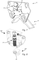
Figure 7 shows the back side of afront plate 12 of aharvesting head 1. A limbingmember 11 is arranged on the front side of thefront plate 12. Asensor 22 is arranged on the back side offront plate 12. The back side being opposite of the front side. Thesensor 22 is a proximity sensor, a magneto inductive sensor. Thesensor 12 is arranged to measure the position of the limbingmember 11. - The
sensor 22 comprises afirst portion 22a and asecond portion 22b. Thefirst portion 22a is arranged on thefront plate 12, on the back side of the front plate. Thesecond portion 22b is arranged on the limbingmember 11. - The
front plate 12 comprises aslit 23. Theslit 23 extends through thefront plate 12 form the front side to the back side. The second portion of thesensor 22b is arranged in theslit 23. -
Figure 8 shows thesensor 22 ofFigure 7 . The first portion of thesensor 22a comprises asensing element 24. The second portion of thesensor 22b comprises atarget 25. Thetarget 25 is in the form of a magnet. Thesensing element 24 is configured to sense the presence of thetarget 25. Thesensor 22 is configured to output an analog signal linearly proportional to the distance between thesensing element 24 and thetarget 25. Thefirst portion 22a has a casing surrounding thesensing element 24. Thesecond portion 22b has a casing surrounding thetarget 25. - With reference to
figures 3 ,4 and6 a method according to the present disclosure will now be described. - A corrected thickness Tc of the
tree trunk 17 is determined by determining a measured thickness T and a deviation D of thetree trunk 17 and calculating a corrected thickness Tc based on the deviation D and the measured thickness T. - The measured thickness T is determined by measuring the angular position of the
front limbing knives rotary encoders 19, and relating the position of thefront limbing knives surface 15. The angular position of thefront limbing knives surface 15, and thereby a measured thickness T, through a conversion table which relates different angular positions of thefront limbing knives tree trunk 17 held in theharvesting head 1. - The deviation D is determined by measuring the position of the limbing
member 11, withlinear contact sensor 21, and relating its position to the glidingsurface 15. The position of the limbingmember 11 being related to the glidingsurface 15, and thereby a deviation D, through a conversion table which relates different positions of the limbingmember 11 to different deviations D of atree trunk 17 held in theharvesting head 1. - The corrected thickness Tc is calculated by subtracting the deviation D from the measured thickness T.
- It is realized by a person skilled in the art that features from various embodiments disclosed herein may be combined with one another in order to provide further alternative embodiments.
- Instead of a pair of
front limbing knives other limbing knife several feed rollers - Instead of measuring the angular position of the
front limbing knives knives - The tree trunk pressing device may be a device separate from a limbing knife. The tree trunk pressing device may be anything as long as it presses the tree trunk in a direction towards a reference surface. A tree trunk surface follower may instead of a limbing
member 11, 11' be a measuringwheel 13. - The tree trunk surface follower may be a device separate from a limbing member or length measuring wheel.
- A reference surface does not need to be a gliding surface, it could be a surface of any size, situated anywhere on the harvesting head as long as the tree trunk is pressed in a direction towards it and the position of a tree trunk pressing device and the position of a tree trunk surface follower is related to it.
- It is possible to measure a thickness of a
tree trunk 17 with theback limbing knives front limbing knives - Several thicknesses of the tree trunk may be determined at several points on the
tree trunk 17 as it is fed through theharvesting head 1, the points separated by a certain length interval, the interval may be 10 centimeters. - Instead of the
linear contact sensor 21, mechanically coupled to the limbingmember 11 byconnection 23, it is possible to use a contact free linear sensor, which would not need theconnection 23. It is also possible to use an angle sensor positioned inside joint 25, the angle sensor could be a rotary encoder or an analog angle sensor. If the tree trunk surface follower is a measuringwheel 13, its position relative to the glidingsurface 15 could be measured by a linear contact sensor coupled to themeasuring wheel 13. It could also be measured by a contact free linear sensor or by an angle sensor such as a rotary encoder or analog angle sensor. - A few alternatives to a tree trunk surface follower and devices pressing it towards a tree trunk surface has been disclosed. The devices can be combined with whichever tree trunk surface follower. For example, a measuring wheel could also be pressed towards the tree trunk surface by a compression spring or a torsion spring.
- In the described method the deviation may also be determined by not only relating the position of the limbing
member 11 to the glidingsurface 15, but also by relating the position of the limbingmember 11 to the measured thickness T of thetree trunk 17. The position of the limbingmember 11 being related to the glidingsurface 15, and thereby a deviation D, through a conversion table which relates different positions of the limbingmember 11 as well as different measured thicknesses T to different deviations D of atree trunk 17 held in theharvesting head 1. - Instead of utilising conversion tables to calculate a thickness or a deviation, it is also possible to calculate a thickness or a deviation directly during the measuring process.
Claims (11)
- A method for determining a thickness of a tree trunk (17) in a harvesting head (1) for forestry, said harvesting head (1) comprisinga thickness measuring arrangement for measuring a measured thickness (T) of a tree trunk (17), said thickness measuring arrangement comprising a tree trunk pressing device (3, 4, 7, 8), for pressing said tree trunk (17) in a direction towards a reference surface (15) of the harvesting head (1), and a first measuring sensor (19) arranged to measure the position of said tree trunk pressing device (3, 4, 7, 8) relative to said reference surface (15), anda deviation measuring arrangement, for measuring a deviation (D) of said tree trunk (17) from said reference surface (15),said deviation measuring arrangement comprising a tree trunk surface follower (11, 13; 11') and a second measuring sensor (21) arranged to measure the position of said tree trunk surface follower (11, 13; 11'),wherein the second measuring sensor is a proximity sensor,wherein the tree trunk surface follower is a limbing member (11, 11'), and wherein the limbing member (11, 11') is curved,said method comprisingpressing the tree trunk (17), with said tree trunk pressing device (3, 4, 7, 8), in a direction towards the reference surface (15) of the harvesting head (1) anddetermining a measured thickness (T) by measuring the position of the tree trunk pressing device (3, 4, 7, 8) by means of the first measuring sensor (19) and relating said position to said reference surface (15),
wherein said method further comprises the steps ofdetermining a deviation (D) of the tree trunk (17) from said reference surface (15) by measuring a position of the curved limbing member (11, 11') by means of the second measuring sensor (21) and relating said position of the curved limbing member (11, 11') to said reference surface (15), andcalculating a corrected thickness (Tc) of the tree trunk (17) based on said measured thickness (T) and said deviation (D),wherein determining the deviation (D) further comprises relating said position of the curved limbing member (11, 11') to said measured thickness (T), anddetermining the deviation (D) as a function of said position of the curved limbing member (11, 11'), a curvature of the limbing member (11, 11') and the measured thickness (T). - A method according to claim 1, wherein the proximity sensor is a magneto-inductive sensor.
- A method according to any of the preceding claims, comprising pressing said tree trunk surface follower (11, 13; 11') against at least a portion of the half of the circumference of the tree trunk (17) which is closest to said reference surface (15).
- A harvesting head (1) for forestry, comprising a thickness measuring arrangement for measuring a measured thickness (T) of a tree trunk (17), said thickness measuring arrangement comprising a tree trunk pressing device (3, 4, 7, 8), for pressing said tree trunk (17) in a direction towards a reference surface (15) of the harvesting head (1), and a first measuring sensor (19) arranged to measure the position of said tree trunk pressing device (3, 4, 7, 8) relative to said reference surface (15),wherein said harvesting head (1) further comprises
a deviation measuring arrangement, for measuring a deviation (D) of said tree trunk (17) from said reference surface (15),said deviation measuring arrangement comprising a tree trunk surface follower (11, 13; 11') and a second measuring sensor (21) arranged to measure the position of said tree trunk surface follower (11, 13; 11'),wherein the tree trunk surface follower is a limbing member (11, 11'),wherein the second measuring sensor is a proximity sensor,wherein the limbing member (11, 11') is arranged on a front side of a front plate of the harvesting head (1),characterized in thatthe second measuring sensor is arranged on a back side of the front plate, the back side being opposite to the front side,the second measuring sensor comprises a first portion and a second portion, andthe first portion is arranged on the front plate and the second portion is arranged on the limbing member. - A harvesting head (1) according to claim 4, wherein the second measuring sensor is a magneto-inductive measuring sensor.
- A harvesting head (1) according to claim 4 or 5, wherein the front plate comprises a slit extending through the front plate from the front side to the back side,wherein the first portion of the second measuring sensor is arranged on the back side of the front plate, andthe second portion of the second measuring sensor is arranged in the slit.
- A harvesting head according to any of claim 4 to 6, wherein
said tree trunk surface follower (11, 13; 11') is arranged to follow at least a portion of the half of the circumference of the tree trunk (17) which is closest to the reference surface (15). - A harvesting head according to any of claims 4 to 7, wherein
said deviation measuring arrangement comprises a torsion spring, a compression spring (29) or a hydraulic piston (27). - A harvesting head according to any of claims 4 to 8, wherein
said tree trunk pressing device comprises at least one limbing knife (3, 4, 7, 8). - A harvesting head according to any of claims 4 to 9, wherein
said tree trunk surface follower (11, 13; 11') is linearly guided. - A harvesting head according to any of claims 4 to 9, wherein
said tree trunk surface follower (11, 13; 11') is pivotally coupled to the harvesting head (1).
Applications Claiming Priority (2)
| Application Number | Priority Date | Filing Date | Title |
|---|---|---|---|
| SE1951383A SE544915C2 (en) | 2019-12-03 | 2019-12-03 | Harvesting head for forestry and a method for determining a thickness of a tree trunk in a harvesting head for forestry |
| PCT/EP2020/084293 WO2021110755A1 (en) | 2019-12-03 | 2020-12-02 | Harvesting head for forestry and a method for determining a thickness of a tree trunk in a harvesting head for forestry |
Publications (3)
| Publication Number | Publication Date |
|---|---|
| EP4068948A1 EP4068948A1 (en) | 2022-10-12 |
| EP4068948B1 true EP4068948B1 (en) | 2025-06-25 |
| EP4068948C0 EP4068948C0 (en) | 2025-06-25 |
Family
ID=73695058
Family Applications (1)
| Application Number | Title | Priority Date | Filing Date |
|---|---|---|---|
| EP20817338.5A Active EP4068948B1 (en) | 2019-12-03 | 2020-12-02 | Harvesting head for forestry and a method for determining a thickness of a tree trunk in a harvesting head for forestry |
Country Status (5)
| Country | Link |
|---|---|
| US (1) | US12317787B2 (en) |
| EP (1) | EP4068948B1 (en) |
| AU (1) | AU2020394817B2 (en) |
| SE (1) | SE544915C2 (en) |
| WO (1) | WO2021110755A1 (en) |
Citations (5)
| Publication number | Priority date | Publication date | Assignee | Title |
|---|---|---|---|---|
| EP0346308B1 (en) | 1988-06-06 | 1991-08-07 | Grangärde Maskin Ab | Delimbing device for a tree |
| US5785101A (en) | 1995-11-14 | 1998-07-28 | Timberjack Inc. | Tree harvesting and processing head |
| WO2000015026A1 (en) | 1998-09-15 | 2000-03-23 | Timberjack Oy | A control arrangement and a method in a delimbing device |
| EP2265894B1 (en) | 2008-04-16 | 2018-06-06 | Log Max AB | Determination of thickness of a tree trunk |
| EP2296852B1 (en) | 2008-06-25 | 2020-10-07 | Log Max AB | Tree delimbing method and device |
Family Cites Families (9)
| Publication number | Priority date | Publication date | Assignee | Title |
|---|---|---|---|---|
| FI106092B (en) * | 1998-06-04 | 2000-11-30 | Ponsse Oyj | Process and device for measuring the diameter of tree trunks |
| FI104531B (en) * | 1998-09-15 | 2000-02-29 | Timberjack Oy | Pruning equipment and method in pruning equipment |
| SE526942C2 (en) * | 2003-11-06 | 2005-11-22 | Fiberpac Kb | Harvester for forest machines and method for measuring the cross-section of a tree trunk |
| FI118320B (en) * | 2005-03-02 | 2007-10-15 | Ponsse Oyj | A method and apparatus for correcting measurement data |
| FI119962B (en) * | 2006-08-31 | 2009-05-29 | Ponsse Oyj | A method and arrangement for measuring a tree unit in a tree handling device |
| DE102011012748B4 (en) * | 2011-03-01 | 2012-10-18 | Bundesrepublik Deutschland, vertr.d.d. Bundesministerium für Wirtschaft und Technologie, d.vertr.d.d. Präsidenten der Physikalisch-Technischen Bundesanstalt | Harvester head for a harvester and method for measuring a diameter of a trunk during harvesting |
| US9554524B2 (en) * | 2012-06-06 | 2017-01-31 | Waratah Nz Limited | Delimb knife with integrated side blades |
| FI20125675L (en) * | 2012-06-18 | 2013-12-19 | Technion Oy | The measuring method of the harvester head of a single-take harvester and the harvester head of a single-take harvester |
| SE542483C2 (en) | 2018-05-24 | 2020-05-19 | Komatsu Forest Ab | Method for measuring a tree trunk and a harvester. |
-
2019
- 2019-12-03 SE SE1951383A patent/SE544915C2/en not_active IP Right Cessation
-
2020
- 2020-12-02 AU AU2020394817A patent/AU2020394817B2/en active Active
- 2020-12-02 US US17/756,549 patent/US12317787B2/en active Active
- 2020-12-02 WO PCT/EP2020/084293 patent/WO2021110755A1/en not_active Ceased
- 2020-12-02 EP EP20817338.5A patent/EP4068948B1/en active Active
Patent Citations (5)
| Publication number | Priority date | Publication date | Assignee | Title |
|---|---|---|---|---|
| EP0346308B1 (en) | 1988-06-06 | 1991-08-07 | Grangärde Maskin Ab | Delimbing device for a tree |
| US5785101A (en) | 1995-11-14 | 1998-07-28 | Timberjack Inc. | Tree harvesting and processing head |
| WO2000015026A1 (en) | 1998-09-15 | 2000-03-23 | Timberjack Oy | A control arrangement and a method in a delimbing device |
| EP2265894B1 (en) | 2008-04-16 | 2018-06-06 | Log Max AB | Determination of thickness of a tree trunk |
| EP2296852B1 (en) | 2008-06-25 | 2020-10-07 | Log Max AB | Tree delimbing method and device |
Non-Patent Citations (7)
| Title |
|---|
| ANONYMOUS: "Log Max - Above and Beyond - Catalogue", LOG MAX, 1 January 2018 (2018-01-01), XP093381953 |
| D10 - a delimbing unit-knife of 5000D |
| D11 - a delimbing unit Sensor of 5000D |
| D5 - SPARE PART MANUAL 5000D PAGE 20-23 |
| D7 - WAY BACK MACHINE, MARCH 3, 2018, MAY 29, 2019, NOVEMBER 20, 2017 |
| D8 - WAY BACK MACHINE, MARCH 8, 2015 |
| D9 - WAY BACK MACHINE, MARCH 7, 2015 |
Also Published As
| Publication number | Publication date |
|---|---|
| SE544915C2 (en) | 2022-12-27 |
| AU2020394817A1 (en) | 2022-06-02 |
| NZ788303A (en) | 2025-08-29 |
| CA3163180A1 (en) | 2021-06-10 |
| US12317787B2 (en) | 2025-06-03 |
| EP4068948A1 (en) | 2022-10-12 |
| WO2021110755A1 (en) | 2021-06-10 |
| AU2020394817B2 (en) | 2025-09-25 |
| SE1951383A1 (en) | 2021-06-04 |
| US20220408664A1 (en) | 2022-12-29 |
| EP4068948C0 (en) | 2025-06-25 |
Similar Documents
| Publication | Publication Date | Title |
|---|---|---|
| US12317787B2 (en) | Harvesting head for forestry and a method for determining a thickness of a tree trunk in a harvesting head for forestry | |
| GB2174202A (en) | Profile gauge | |
| FI118320B (en) | A method and apparatus for correcting measurement data | |
| US10030423B2 (en) | Movable joint | |
| US20100292955A1 (en) | Method and Apparatus for Measuring Microrelief of an Object | |
| ATE313420T1 (en) | SAWING METHOD FOR CUTTING A WOODEN BOARD | |
| CN110024656B (en) | Method and apparatus for measurement of wood harvested by combined harvesting heads | |
| AU2019275194B2 (en) | Method for measuring a tree trunk, and a harvester | |
| US8746116B2 (en) | Method and apparatus for making wide cuts | |
| CA2616753A1 (en) | Systems and methods for measuring height of jointer infeed surface | |
| WO2013190179A1 (en) | Measuring method for harvester head of single-grip harvester, and harvester head of single-grip harvester | |
| NZ788303B2 (en) | Harvesting head for forestry and a method for determining a thickness of a tree trunk in a harvesting head for forestry | |
| CN212241332U (en) | Cutter structure and glued membrane cutting device | |
| US6457248B1 (en) | Measurement of inclination between spaced-apart workpiece surfaces | |
| CN221364892U (en) | Asynchronous non-interval cutting mechanism | |
| CA1131551A (en) | Machine for hewing square timbers | |
| CN211152795U (en) | Vegetable harvesting and cutting depth profiling control device matched with tractor | |
| FI123897B (en) | Control arrangement for a measurement, data transfer and blade station that joins wood sawing | |
| CA3258530A1 (en) | Tree processing machine with log measuring system and method for calibrating a log measuring system | |
| ES456939A1 (en) | Gauges for measuring the taper angles of tapered piston rings | |
| SE543752C2 (en) | A harvesting head for length determination of a tree truck and an associated method | |
| JPS5815132Y2 (en) | Material cutting width display device for band saw | |
| DD255904A1 (en) | DEVICE FOR MEASURING LENGTH | |
| FI81985B (en) | Device for sawing crooked timber pieces | |
| AT359683B (en) | DEVICE FOR THE CONTINUOUSLY ADJUSTING THE ANGLE POSITION OF A SECTION THAT SWIVELS BEARED ON THE UNDERMATER OF A LIVING FURNITURE, IN PARTICULAR A FOOT POSITIONING OR HEAD PART |
Legal Events
| Date | Code | Title | Description |
|---|---|---|---|
| STAA | Information on the status of an ep patent application or granted ep patent |
Free format text: STATUS: UNKNOWN |
|
| STAA | Information on the status of an ep patent application or granted ep patent |
Free format text: STATUS: THE INTERNATIONAL PUBLICATION HAS BEEN MADE |
|
| PUAI | Public reference made under article 153(3) epc to a published international application that has entered the european phase |
Free format text: ORIGINAL CODE: 0009012 |
|
| STAA | Information on the status of an ep patent application or granted ep patent |
Free format text: STATUS: REQUEST FOR EXAMINATION WAS MADE |
|
| 17P | Request for examination filed |
Effective date: 20220610 |
|
| AK | Designated contracting states |
Kind code of ref document: A1 Designated state(s): AL AT BE BG CH CY CZ DE DK EE ES FI FR GB GR HR HU IE IS IT LI LT LU LV MC MK MT NL NO PL PT RO RS SE SI SK SM TR |
|
| DAV | Request for validation of the european patent (deleted) | ||
| DAX | Request for extension of the european patent (deleted) | ||
| STAA | Information on the status of an ep patent application or granted ep patent |
Free format text: STATUS: EXAMINATION IS IN PROGRESS |
|
| 17Q | First examination report despatched |
Effective date: 20240923 |
|
| GRAP | Despatch of communication of intention to grant a patent |
Free format text: ORIGINAL CODE: EPIDOSNIGR1 |
|
| STAA | Information on the status of an ep patent application or granted ep patent |
Free format text: STATUS: GRANT OF PATENT IS INTENDED |
|
| INTG | Intention to grant announced |
Effective date: 20241107 |
|
| GRAJ | Information related to disapproval of communication of intention to grant by the applicant or resumption of examination proceedings by the epo deleted |
Free format text: ORIGINAL CODE: EPIDOSDIGR1 |
|
| STAA | Information on the status of an ep patent application or granted ep patent |
Free format text: STATUS: EXAMINATION IS IN PROGRESS |
|
| GRAP | Despatch of communication of intention to grant a patent |
Free format text: ORIGINAL CODE: EPIDOSNIGR1 |
|
| INTC | Intention to grant announced (deleted) | ||
| STAA | Information on the status of an ep patent application or granted ep patent |
Free format text: STATUS: GRANT OF PATENT IS INTENDED |
|
| INTG | Intention to grant announced |
Effective date: 20250410 |
|
| GRAS | Grant fee paid |
Free format text: ORIGINAL CODE: EPIDOSNIGR3 |
|
| GRAA | (expected) grant |
Free format text: ORIGINAL CODE: 0009210 |
|
| STAA | Information on the status of an ep patent application or granted ep patent |
Free format text: STATUS: THE PATENT HAS BEEN GRANTED |
|
| AK | Designated contracting states |
Kind code of ref document: B1 Designated state(s): AL AT BE BG CH CY CZ DE DK EE ES FI FR GB GR HR HU IE IS IT LI LT LU LV MC MK MT NL NO PL PT RO RS SE SI SK SM TR |
|
| REG | Reference to a national code |
Ref country code: GB Ref legal event code: FG4D |
|
| REG | Reference to a national code |
Ref country code: CH Ref legal event code: EP |
|
| REG | Reference to a national code |
Ref country code: CH Ref legal event code: EP |
|
| REG | Reference to a national code |
Ref country code: IE Ref legal event code: FG4D |
|
| REG | Reference to a national code |
Ref country code: DE Ref legal event code: R096 Ref document number: 602020053418 Country of ref document: DE |
|
| U01 | Request for unitary effect filed |
Effective date: 20250702 |
|
| U07 | Unitary effect registered |
Designated state(s): AT BE BG DE DK EE FI FR IT LT LU LV MT NL PT RO SE SI Effective date: 20250710 |
|
| PG25 | Lapsed in a contracting state [announced via postgrant information from national office to epo] |
Ref country code: NO Free format text: LAPSE BECAUSE OF FAILURE TO SUBMIT A TRANSLATION OF THE DESCRIPTION OR TO PAY THE FEE WITHIN THE PRESCRIBED TIME-LIMIT Effective date: 20250925 Ref country code: GR Free format text: LAPSE BECAUSE OF FAILURE TO SUBMIT A TRANSLATION OF THE DESCRIPTION OR TO PAY THE FEE WITHIN THE PRESCRIBED TIME-LIMIT Effective date: 20250926 |
|
| PG25 | Lapsed in a contracting state [announced via postgrant information from national office to epo] |
Ref country code: HR Free format text: LAPSE BECAUSE OF FAILURE TO SUBMIT A TRANSLATION OF THE DESCRIPTION OR TO PAY THE FEE WITHIN THE PRESCRIBED TIME-LIMIT Effective date: 20250625 |
|
| PG25 | Lapsed in a contracting state [announced via postgrant information from national office to epo] |
Ref country code: RS Free format text: LAPSE BECAUSE OF FAILURE TO SUBMIT A TRANSLATION OF THE DESCRIPTION OR TO PAY THE FEE WITHIN THE PRESCRIBED TIME-LIMIT Effective date: 20250925 |
|
| U20 | Renewal fee for the european patent with unitary effect paid |
Year of fee payment: 6 Effective date: 20251117 |
|
| PG25 | Lapsed in a contracting state [announced via postgrant information from national office to epo] |
Ref country code: IS Free format text: LAPSE BECAUSE OF FAILURE TO SUBMIT A TRANSLATION OF THE DESCRIPTION OR TO PAY THE FEE WITHIN THE PRESCRIBED TIME-LIMIT Effective date: 20251025 |
|
| PGFP | Annual fee paid to national office [announced via postgrant information from national office to epo] |
Ref country code: GB Payment date: 20251117 Year of fee payment: 6 |
|
| PG25 | Lapsed in a contracting state [announced via postgrant information from national office to epo] |
Ref country code: SM Free format text: LAPSE BECAUSE OF FAILURE TO SUBMIT A TRANSLATION OF THE DESCRIPTION OR TO PAY THE FEE WITHIN THE PRESCRIBED TIME-LIMIT Effective date: 20250625 |
|
| PG25 | Lapsed in a contracting state [announced via postgrant information from national office to epo] |
Ref country code: CZ Free format text: LAPSE BECAUSE OF FAILURE TO SUBMIT A TRANSLATION OF THE DESCRIPTION OR TO PAY THE FEE WITHIN THE PRESCRIBED TIME-LIMIT Effective date: 20250625 |
|
| PG25 | Lapsed in a contracting state [announced via postgrant information from national office to epo] |
Ref country code: PL Free format text: LAPSE BECAUSE OF FAILURE TO SUBMIT A TRANSLATION OF THE DESCRIPTION OR TO PAY THE FEE WITHIN THE PRESCRIBED TIME-LIMIT Effective date: 20250625 |
|
| PG25 | Lapsed in a contracting state [announced via postgrant information from national office to epo] |
Ref country code: SK Free format text: LAPSE BECAUSE OF FAILURE TO SUBMIT A TRANSLATION OF THE DESCRIPTION OR TO PAY THE FEE WITHIN THE PRESCRIBED TIME-LIMIT Effective date: 20250625 |
|
| PG25 | Lapsed in a contracting state [announced via postgrant information from national office to epo] |
Ref country code: ES Free format text: LAPSE BECAUSE OF FAILURE TO SUBMIT A TRANSLATION OF THE DESCRIPTION OR TO PAY THE FEE WITHIN THE PRESCRIBED TIME-LIMIT Effective date: 20250625 |
|
| PLBI | Opposition filed |
Free format text: ORIGINAL CODE: 0009260 |
|
| REG | Reference to a national code |
Ref country code: CH Ref legal event code: L10 Free format text: ST27 STATUS EVENT CODE: U-0-0-L10-L00 (AS PROVIDED BY THE NATIONAL OFFICE) Effective date: 20260402 |
|
| PLAX | Notice of opposition and request to file observation + time limit sent |
Free format text: ORIGINAL CODE: EPIDOSNOBS2 |
|
| 26 | Opposition filed |
Opponent name: LOG MAX AB Effective date: 20260325 |
|
| PG25 | Lapsed in a contracting state [announced via postgrant information from national office to epo] |
Ref country code: MC Free format text: LAPSE BECAUSE OF FAILURE TO SUBMIT A TRANSLATION OF THE DESCRIPTION OR TO PAY THE FEE WITHIN THE PRESCRIBED TIME-LIMIT Effective date: 20250625 |
|
| REG | Reference to a national code |
Ref country code: CH Ref legal event code: H13 Free format text: ST27 STATUS EVENT CODE: U-0-0-H10-H13 (AS PROVIDED BY THE NATIONAL OFFICE) Effective date: 20260723 |
|
| PLBB | Reply of patent proprietor to notice(s) of opposition received |
Free format text: ORIGINAL CODE: EPIDOSNOBS3 |