EP4068603A1 - Verfahren und vorrichtung zur steuerung eines gleichstromwandlers - Google Patents
Verfahren und vorrichtung zur steuerung eines gleichstromwandlers Download PDFInfo
- Publication number
- EP4068603A1 EP4068603A1 EP21763898.0A EP21763898A EP4068603A1 EP 4068603 A1 EP4068603 A1 EP 4068603A1 EP 21763898 A EP21763898 A EP 21763898A EP 4068603 A1 EP4068603 A1 EP 4068603A1
- Authority
- EP
- European Patent Office
- Prior art keywords
- power
- terminal
- input
- electric motor
- preset value
- Prior art date
- Legal status (The legal status is an assumption and is not a legal conclusion. Google has not performed a legal analysis and makes no representation as to the accuracy of the status listed.)
- Pending
Links
Images


Classifications
-
- H—ELECTRICITY
- H02—GENERATION; CONVERSION OR DISTRIBUTION OF ELECTRIC POWER
- H02M—APPARATUS FOR CONVERSION BETWEEN AC AND AC, BETWEEN AC AND DC, OR BETWEEN DC AND DC, AND FOR USE WITH MAINS OR SIMILAR POWER SUPPLY SYSTEMS; CONVERSION OF DC OR AC INPUT POWER INTO SURGE OUTPUT POWER; CONTROL OR REGULATION THEREOF
- H02M1/00—Details of apparatus for conversion
- H02M1/0003—Details of control, feedback or regulation circuits
- H02M1/0006—Arrangements for supplying an adequate voltage to the control circuit of converters
-
- H—ELECTRICITY
- H02—GENERATION; CONVERSION OR DISTRIBUTION OF ELECTRIC POWER
- H02J—CIRCUIT ARRANGEMENTS OR SYSTEMS FOR SUPPLYING OR DISTRIBUTING ELECTRIC POWER; SYSTEMS FOR STORING ELECTRIC ENERGY
- H02J7/00—Circuit arrangements for charging or depolarising batteries or for supplying loads from batteries
- H02J7/34—Parallel operation in networks using both storage and other dc sources, e.g. providing buffering
- H02J7/342—The other DC source being a battery actively interacting with the first one, i.e. battery to battery charging
-
- H—ELECTRICITY
- H02—GENERATION; CONVERSION OR DISTRIBUTION OF ELECTRIC POWER
- H02M—APPARATUS FOR CONVERSION BETWEEN AC AND AC, BETWEEN AC AND DC, OR BETWEEN DC AND DC, AND FOR USE WITH MAINS OR SIMILAR POWER SUPPLY SYSTEMS; CONVERSION OF DC OR AC INPUT POWER INTO SURGE OUTPUT POWER; CONTROL OR REGULATION THEREOF
- H02M3/00—Conversion of dc power input into dc power output
-
- B—PERFORMING OPERATIONS; TRANSPORTING
- B60—VEHICLES IN GENERAL
- B60L—PROPULSION OF ELECTRICALLY-PROPELLED VEHICLES; SUPPLYING ELECTRIC POWER FOR AUXILIARY EQUIPMENT OF ELECTRICALLY-PROPELLED VEHICLES; ELECTRODYNAMIC BRAKE SYSTEMS FOR VEHICLES IN GENERAL; MAGNETIC SUSPENSION OR LEVITATION FOR VEHICLES; MONITORING OPERATING VARIABLES OF ELECTRICALLY-PROPELLED VEHICLES; ELECTRIC SAFETY DEVICES FOR ELECTRICALLY-PROPELLED VEHICLES
- B60L1/00—Supplying electric power to auxiliary equipment of vehicles
-
- B—PERFORMING OPERATIONS; TRANSPORTING
- B60—VEHICLES IN GENERAL
- B60L—PROPULSION OF ELECTRICALLY-PROPELLED VEHICLES; SUPPLYING ELECTRIC POWER FOR AUXILIARY EQUIPMENT OF ELECTRICALLY-PROPELLED VEHICLES; ELECTRODYNAMIC BRAKE SYSTEMS FOR VEHICLES IN GENERAL; MAGNETIC SUSPENSION OR LEVITATION FOR VEHICLES; MONITORING OPERATING VARIABLES OF ELECTRICALLY-PROPELLED VEHICLES; ELECTRIC SAFETY DEVICES FOR ELECTRICALLY-PROPELLED VEHICLES
- B60L15/00—Methods, circuits, or devices for controlling the traction-motor speed of electrically-propelled vehicles
- B60L15/007—Physical arrangements or structures of drive train converters specially adapted for the propulsion motors of electric vehicles
-
- B—PERFORMING OPERATIONS; TRANSPORTING
- B60—VEHICLES IN GENERAL
- B60L—PROPULSION OF ELECTRICALLY-PROPELLED VEHICLES; SUPPLYING ELECTRIC POWER FOR AUXILIARY EQUIPMENT OF ELECTRICALLY-PROPELLED VEHICLES; ELECTRODYNAMIC BRAKE SYSTEMS FOR VEHICLES IN GENERAL; MAGNETIC SUSPENSION OR LEVITATION FOR VEHICLES; MONITORING OPERATING VARIABLES OF ELECTRICALLY-PROPELLED VEHICLES; ELECTRIC SAFETY DEVICES FOR ELECTRICALLY-PROPELLED VEHICLES
- B60L15/00—Methods, circuits, or devices for controlling the traction-motor speed of electrically-propelled vehicles
- B60L15/20—Methods, circuits, or devices for controlling the traction-motor speed of electrically-propelled vehicles for control of the vehicle or its driving motor to achieve a desired performance, e.g. speed, torque, programmed variation of speed
-
- B—PERFORMING OPERATIONS; TRANSPORTING
- B60—VEHICLES IN GENERAL
- B60L—PROPULSION OF ELECTRICALLY-PROPELLED VEHICLES; SUPPLYING ELECTRIC POWER FOR AUXILIARY EQUIPMENT OF ELECTRICALLY-PROPELLED VEHICLES; ELECTRODYNAMIC BRAKE SYSTEMS FOR VEHICLES IN GENERAL; MAGNETIC SUSPENSION OR LEVITATION FOR VEHICLES; MONITORING OPERATING VARIABLES OF ELECTRICALLY-PROPELLED VEHICLES; ELECTRIC SAFETY DEVICES FOR ELECTRICALLY-PROPELLED VEHICLES
- B60L58/00—Methods or circuit arrangements for monitoring or controlling batteries or fuel cells, specially adapted for electric vehicles
- B60L58/10—Methods or circuit arrangements for monitoring or controlling batteries or fuel cells, specially adapted for electric vehicles for monitoring or controlling batteries
- B60L58/12—Methods or circuit arrangements for monitoring or controlling batteries or fuel cells, specially adapted for electric vehicles for monitoring or controlling batteries responding to state of charge [SoC]
- B60L58/13—Maintaining the SoC within a determined range
-
- H—ELECTRICITY
- H02—GENERATION; CONVERSION OR DISTRIBUTION OF ELECTRIC POWER
- H02J—CIRCUIT ARRANGEMENTS OR SYSTEMS FOR SUPPLYING OR DISTRIBUTING ELECTRIC POWER; SYSTEMS FOR STORING ELECTRIC ENERGY
- H02J7/00—Circuit arrangements for charging or depolarising batteries or for supplying loads from batteries
- H02J7/0047—Circuit arrangements for charging or depolarising batteries or for supplying loads from batteries with monitoring or indicating devices or circuits
- H02J7/0048—Detection of remaining charge capacity or state of charge [SOC]
-
- H—ELECTRICITY
- H02—GENERATION; CONVERSION OR DISTRIBUTION OF ELECTRIC POWER
- H02J—CIRCUIT ARRANGEMENTS OR SYSTEMS FOR SUPPLYING OR DISTRIBUTING ELECTRIC POWER; SYSTEMS FOR STORING ELECTRIC ENERGY
- H02J7/00—Circuit arrangements for charging or depolarising batteries or for supplying loads from batteries
- H02J7/0068—Battery or charger load switching, e.g. concurrent charging and load supply
-
- H—ELECTRICITY
- H02—GENERATION; CONVERSION OR DISTRIBUTION OF ELECTRIC POWER
- H02J—CIRCUIT ARRANGEMENTS OR SYSTEMS FOR SUPPLYING OR DISTRIBUTING ELECTRIC POWER; SYSTEMS FOR STORING ELECTRIC ENERGY
- H02J7/00—Circuit arrangements for charging or depolarising batteries or for supplying loads from batteries
- H02J7/007—Regulation of charging or discharging current or voltage
- H02J7/00712—Regulation of charging or discharging current or voltage the cycle being controlled or terminated in response to electric parameters
-
- H—ELECTRICITY
- H02—GENERATION; CONVERSION OR DISTRIBUTION OF ELECTRIC POWER
- H02M—APPARATUS FOR CONVERSION BETWEEN AC AND AC, BETWEEN AC AND DC, OR BETWEEN DC AND DC, AND FOR USE WITH MAINS OR SIMILAR POWER SUPPLY SYSTEMS; CONVERSION OF DC OR AC INPUT POWER INTO SURGE OUTPUT POWER; CONTROL OR REGULATION THEREOF
- H02M1/00—Details of apparatus for conversion
- H02M1/0003—Details of control, feedback or regulation circuits
-
- B—PERFORMING OPERATIONS; TRANSPORTING
- B60—VEHICLES IN GENERAL
- B60L—PROPULSION OF ELECTRICALLY-PROPELLED VEHICLES; SUPPLYING ELECTRIC POWER FOR AUXILIARY EQUIPMENT OF ELECTRICALLY-PROPELLED VEHICLES; ELECTRODYNAMIC BRAKE SYSTEMS FOR VEHICLES IN GENERAL; MAGNETIC SUSPENSION OR LEVITATION FOR VEHICLES; MONITORING OPERATING VARIABLES OF ELECTRICALLY-PROPELLED VEHICLES; ELECTRIC SAFETY DEVICES FOR ELECTRICALLY-PROPELLED VEHICLES
- B60L2210/00—Converter types
- B60L2210/10—DC to DC converters
-
- B—PERFORMING OPERATIONS; TRANSPORTING
- B60—VEHICLES IN GENERAL
- B60L—PROPULSION OF ELECTRICALLY-PROPELLED VEHICLES; SUPPLYING ELECTRIC POWER FOR AUXILIARY EQUIPMENT OF ELECTRICALLY-PROPELLED VEHICLES; ELECTRODYNAMIC BRAKE SYSTEMS FOR VEHICLES IN GENERAL; MAGNETIC SUSPENSION OR LEVITATION FOR VEHICLES; MONITORING OPERATING VARIABLES OF ELECTRICALLY-PROPELLED VEHICLES; ELECTRIC SAFETY DEVICES FOR ELECTRICALLY-PROPELLED VEHICLES
- B60L2240/00—Control parameters of input or output; Target parameters
- B60L2240/40—Drive Train control parameters
- B60L2240/52—Drive Train control parameters related to converters
- B60L2240/525—Temperature of converter or components thereof
-
- B—PERFORMING OPERATIONS; TRANSPORTING
- B60—VEHICLES IN GENERAL
- B60L—PROPULSION OF ELECTRICALLY-PROPELLED VEHICLES; SUPPLYING ELECTRIC POWER FOR AUXILIARY EQUIPMENT OF ELECTRICALLY-PROPELLED VEHICLES; ELECTRODYNAMIC BRAKE SYSTEMS FOR VEHICLES IN GENERAL; MAGNETIC SUSPENSION OR LEVITATION FOR VEHICLES; MONITORING OPERATING VARIABLES OF ELECTRICALLY-PROPELLED VEHICLES; ELECTRIC SAFETY DEVICES FOR ELECTRICALLY-PROPELLED VEHICLES
- B60L2240/00—Control parameters of input or output; Target parameters
- B60L2240/40—Drive Train control parameters
- B60L2240/52—Drive Train control parameters related to converters
- B60L2240/527—Voltage
-
- B—PERFORMING OPERATIONS; TRANSPORTING
- B60—VEHICLES IN GENERAL
- B60L—PROPULSION OF ELECTRICALLY-PROPELLED VEHICLES; SUPPLYING ELECTRIC POWER FOR AUXILIARY EQUIPMENT OF ELECTRICALLY-PROPELLED VEHICLES; ELECTRODYNAMIC BRAKE SYSTEMS FOR VEHICLES IN GENERAL; MAGNETIC SUSPENSION OR LEVITATION FOR VEHICLES; MONITORING OPERATING VARIABLES OF ELECTRICALLY-PROPELLED VEHICLES; ELECTRIC SAFETY DEVICES FOR ELECTRICALLY-PROPELLED VEHICLES
- B60L2240/00—Control parameters of input or output; Target parameters
- B60L2240/40—Drive Train control parameters
- B60L2240/52—Drive Train control parameters related to converters
- B60L2240/529—Current
-
- B—PERFORMING OPERATIONS; TRANSPORTING
- B60—VEHICLES IN GENERAL
- B60L—PROPULSION OF ELECTRICALLY-PROPELLED VEHICLES; SUPPLYING ELECTRIC POWER FOR AUXILIARY EQUIPMENT OF ELECTRICALLY-PROPELLED VEHICLES; ELECTRODYNAMIC BRAKE SYSTEMS FOR VEHICLES IN GENERAL; MAGNETIC SUSPENSION OR LEVITATION FOR VEHICLES; MONITORING OPERATING VARIABLES OF ELECTRICALLY-PROPELLED VEHICLES; ELECTRIC SAFETY DEVICES FOR ELECTRICALLY-PROPELLED VEHICLES
- B60L2240/00—Control parameters of input or output; Target parameters
- B60L2240/40—Drive Train control parameters
- B60L2240/54—Drive Train control parameters related to batteries
- B60L2240/547—Voltage
-
- B—PERFORMING OPERATIONS; TRANSPORTING
- B60—VEHICLES IN GENERAL
- B60L—PROPULSION OF ELECTRICALLY-PROPELLED VEHICLES; SUPPLYING ELECTRIC POWER FOR AUXILIARY EQUIPMENT OF ELECTRICALLY-PROPELLED VEHICLES; ELECTRODYNAMIC BRAKE SYSTEMS FOR VEHICLES IN GENERAL; MAGNETIC SUSPENSION OR LEVITATION FOR VEHICLES; MONITORING OPERATING VARIABLES OF ELECTRICALLY-PROPELLED VEHICLES; ELECTRIC SAFETY DEVICES FOR ELECTRICALLY-PROPELLED VEHICLES
- B60L2240/00—Control parameters of input or output; Target parameters
- B60L2240/40—Drive Train control parameters
- B60L2240/54—Drive Train control parameters related to batteries
- B60L2240/549—Current
-
- H—ELECTRICITY
- H02—GENERATION; CONVERSION OR DISTRIBUTION OF ELECTRIC POWER
- H02J—CIRCUIT ARRANGEMENTS OR SYSTEMS FOR SUPPLYING OR DISTRIBUTING ELECTRIC POWER; SYSTEMS FOR STORING ELECTRIC ENERGY
- H02J2207/00—Indexing scheme relating to details of circuit arrangements for charging or depolarising batteries or for supplying loads from batteries
- H02J2207/20—Charging or discharging characterised by the power electronics converter
-
- H—ELECTRICITY
- H02—GENERATION; CONVERSION OR DISTRIBUTION OF ELECTRIC POWER
- H02J—CIRCUIT ARRANGEMENTS OR SYSTEMS FOR SUPPLYING OR DISTRIBUTING ELECTRIC POWER; SYSTEMS FOR STORING ELECTRIC ENERGY
- H02J2310/00—The network for supplying or distributing electric power characterised by its spatial reach or by the load
- H02J2310/40—The network being an on-board power network, i.e. within a vehicle
- H02J2310/48—The network being an on-board power network, i.e. within a vehicle for electric vehicles [EV] or hybrid vehicles [HEV]
-
- H—ELECTRICITY
- H02—GENERATION; CONVERSION OR DISTRIBUTION OF ELECTRIC POWER
- H02M—APPARATUS FOR CONVERSION BETWEEN AC AND AC, BETWEEN AC AND DC, OR BETWEEN DC AND DC, AND FOR USE WITH MAINS OR SIMILAR POWER SUPPLY SYSTEMS; CONVERSION OF DC OR AC INPUT POWER INTO SURGE OUTPUT POWER; CONTROL OR REGULATION THEREOF
- H02M3/00—Conversion of dc power input into dc power output
- H02M3/02—Conversion of dc power input into dc power output without intermediate conversion into ac
- H02M3/04—Conversion of dc power input into dc power output without intermediate conversion into ac by static converters
-
- Y—GENERAL TAGGING OF NEW TECHNOLOGICAL DEVELOPMENTS; GENERAL TAGGING OF CROSS-SECTIONAL TECHNOLOGIES SPANNING OVER SEVERAL SECTIONS OF THE IPC; TECHNICAL SUBJECTS COVERED BY FORMER USPC CROSS-REFERENCE ART COLLECTIONS [XRACs] AND DIGESTS
- Y02—TECHNOLOGIES OR APPLICATIONS FOR MITIGATION OR ADAPTATION AGAINST CLIMATE CHANGE
- Y02T—CLIMATE CHANGE MITIGATION TECHNOLOGIES RELATED TO TRANSPORTATION
- Y02T10/00—Road transport of goods or passengers
- Y02T10/60—Other road transportation technologies with climate change mitigation effect
- Y02T10/70—Energy storage systems for electromobility, e.g. batteries
Definitions
- the present disclosure relates to the technical field of vehicle controlling, and more particularly, to a method and apparatus for controlling a DCDC converter.
- the Direct Current Direct Current (DCDC) converter is an important component for maintaining the normal operation of the low-voltage loop for a hybrid-power vehicle, and its function is to convert the high voltage inputted by the power source such as a high-voltage battery and a generator into a low voltage required by a low-voltage load such as a storage battery.
- the conversion efficiency of the DCDC converter is an important parameter of the DCDC converter.
- the voltage at its output terminal should be non-constant, which means that it is required that the power of the input terminal should be dynamically followed.
- a single input power constraint cannot satisfy the electricity-consumption requirements in various working conditions.
- a too low power constraint affects the normal usage of the low-voltage components and the stability of the vehicle controller. If the power constraint is too high, the DCDC converter does not reach the maximum usage efficiency, which results in the waste of the energy of the hybrid-power vehicle.
- the restriction strategy is not abundant. Only the protection of the stability of the low-voltage controller and the safety of the low-voltage storage battery are taken into consideration, and the allocation of the power source at the input terminal is not comprehensively considered, which cannot satisfy multiple combined working conditions in which the power source of the input terminal is sufficient or insufficient, and results in that the DCDC converters have few uses and the accuracy is low.
- the present disclosure provides a method and apparatus for controlling a DCDC converter, to solve the problems of DCDC converters of few uses and the accuracy is low.
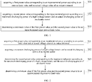
- FIG. 1 shows a flow chart of the steps of the method for controlling a DCDC converter according to the first embodiment of the present disclosure.
- the method for controlling a DCDC converter may be applied to a hybrid-power vehicle.
- the method for controlling a DCDC converter may particularly include the following steps: Step 101: acquiring a first preset value corresponding to an input-terminal power according to a current limit value and an actual voltage value of an output-terminal.
- the DCDC converter is an important component for maintaining the normal operation of the low-voltage loop for a hybrid-power vehicle, and its function is to convert the high voltage inputted by the power source such as a high-voltage battery and a generator into a low voltage required by a low-voltage load such as a storage battery.
- the voltage at the output terminal should be non-constant, which means that it is required that the power of the input terminal should be dynamically followed.
- a single input power constraint cannot satisfy the electricity-consumption requirements in various working conditions.
- a too low power constraint affects the normal usage of the low-voltage components and the stability of the vehicle controller. If the power constraint is too high, the DCDC converter does not reach the maximum usage efficiency, which results in the waste of the energy of the hybrid-power vehicle.
- the first preset value corresponding to the input-terminal power refers to the first preset value of the constraint of the input-terminal power of the DCDC converter.
- the particular implementation process of the step 101 may include: Sub-step S1: acquiring the current limit value and the actual voltage value of the output terminal; and acquiring a conversion efficiency of the DCDC converter.
- Acquiring the current limit value of the output terminal may include: firstly, acquiring a current protection value of a low-voltage loop and a storage-battery current limit value; and, subsequently determining the current limit value of the output terminal according to the current protection value and the storage-battery current limit value.
- the calculation is performed according to the current protection value of the low-voltage loop and the storage-battery current limit value.
- the storage-battery current limit value is calibrated based on the temperature and the quantity of electric charge, and its particular value is not limited in the embodiments of the present disclosure, and may be adjusted according to particular practical applications.
- Sub-step S2 determining the first preset value corresponding to the input-terminal power according to the current limit value and the actual voltage value of the output terminal and the conversion efficiency of the DCDC converter.
- the current limit value of the output terminal refers to the current limit value at the output terminal of the DCDC converter. According to the current limit value and the actual voltage value of the output terminal and the conversion efficiency of the DCDC converter, the first preset value corresponding to the input-terminal power is determined.
- the step 102 After acquiring the first preset value corresponding to the input-terminal power according to the current limit value and the actual voltage value of the output-terminal, the step 102 is executed.
- Step 102 acquiring a second preset value corresponding to the input-terminal power according to a maximum discharging power of a high-voltage battery and an actual discharging power of an electric motor.
- the second preset value corresponding to the input-terminal power refers to the second preset value of the constraint of the input-terminal power of the DCDC converter.
- the maximum discharging power refers to the maximum continuous-discharging power of the battery, and particularly refers to the maximum discharging capacity of the battery within 10 seconds that is sent by the battery managing system according to the real-time parameters (for example, the quantity of electric charge and the temperature).
- the actual discharging power of an electric motor refers to the actual electric power that is obtained by the electric-machine controlling unit by calculation according to the discharging current and voltage detected by itself in the generation state.
- This step may include, firstly, acquiring a maximum discharging power of a high-voltage battery and an actual discharging power of an electric motor; and, subsequently, determining the second preset value corresponding to the input-terminal power according to the maximum discharging power of a high-voltage battery and the actual discharging power of an electric motor.
- the actual states of the high-voltage battery and the electric motor may serve as the determining conditions for selecting different calculating methods.
- the electric motor can be divided into a driving state and a generating state.
- the high-voltage battery can be divided into a discharging state and a charging state.
- the maximum discharging power of a high-voltage battery is determined to be the second preset value corresponding to the input-terminal power.
- the high-voltage battery when the electric motor is in the driving state, the high-voltage battery is in and can merely be in the discharging state, at which point the function of the electric motor is to convert the electric energy supplied by the high-voltage battery into the mechanical energy for the driving of the entire vehicle, and the high-voltage battery is the unique power-supply device in the high-voltage power system. Therefore, the maximum discharging power of a high-voltage battery is used as the second preset value corresponding to the input-terminal power.
- the sum of the absolute value of the maximum discharging power of a high-voltage battery and the absolute value of the actual discharging power of an electric motor is determined to be the second preset value corresponding to the input-terminal power.
- the electric motor when the electric motor is in the generation state, the electric motor converts its own mechanical energy into electric energy, and the electric energy that it generates is preferentially supplied to the high-voltage loads such as the DCDC converter. If the supply of the electric motor is insufficient, the high-voltage battery supplements (the electric motor is in the discharging state), at which point the electric motor and the high-voltage battery jointly serve as the power-supply device in the high-voltage power system. If the supply of the electric motor is sufficient, the remaining electric energy is stored in the high-voltage battery (the battery is in the charging state), at which point the electric motor is the unique power-supply device in the high-voltage power system.
- the sum of the absolute value of the maximum discharging power of a high-voltage battery and the absolute value of the actual discharging power of an electric motor is determined to be the second preset value corresponding to the input-terminal power.
- the absolute value of the actual discharging power of an electric motor is determined to be the second preset value corresponding to the input-terminal power.
- the electric motor when the electric motor is in the discharging state and the high-voltage battery is in the charging state, the electric motor converts its own mechanical energy into electric energy, part of the electric energy that the electric motor generates is supplied to the high-voltage loads such as the DCDC converter, and the excessive part is stored in the high-voltage battery (the battery is in the charging state), at which point the electric motor and the high-voltage battery jointly serve as the power-supply device in the high-voltage power system, and the absolute value of the actual discharging power of an electric motor is determined to be the second preset value corresponding to the input-terminal power.
- the step 103 After acquiring the second preset value corresponding to the input-terminal power according to the maximum discharging power of a high-voltage battery and the actual discharging power of an electric motor, the step 103 is executed.
- Step 103 determining a minimum value of the first preset value and the second preset value to be an input-terminal target-power limit value.
- the minimum value of the first preset value and the second preset value is selected as the maximum power limit value of the DCDC converter, i.e., as the input-terminal target-power limit value.
- the method for controlling a DCDC converter includes, acquiring a first preset value corresponding to an input-terminal power according to an current limit value and an actual voltage value of an output-terminal; acquiring a second preset value corresponding to the input-terminal power according to a maximum discharging power of a high-voltage battery and an actual discharging power of an electric motor; and determining a minimum value of the first preset value and the second preset value to be an input-terminal target-power limit value.
- the method takes into consideration multiple combined working conditions in which the power source of the input terminal is sufficient or insufficient, which improves the safety of the low-voltage system and the stability of the vehicle controller of the hybrid-power vehicle, ensures the usage efficiency of the DCDC converter to the utmost extent, and improves the use diversity and the accuracy of the DCDC converter.
- FIG. 2 shows a flow chart of the steps of the method for controlling a DCDC converter according to the second embodiment of the present disclosure.
- the method for controlling a DCDC converter is applied to a hybrid-power vehicle.
- the method for controlling a DCDC converter may particularly include the following steps:
- Step 201 acquiring a first preset value corresponding to an input-terminal power according to an current limit value and an actual voltage value of an output-terminal.
- the first preset value corresponding to the input-terminal power refers to the first preset value of the constraint of the input-terminal power of the DCDC converter.
- FIG. 3 shows a schematic structural diagram of a DCDC converting system according to an embodiment of the present disclosure. As shown in FIG. 3 , the system includes a low-voltage load, a DCDC converter, an electric motor and a high-voltage battery.
- the low-voltage load may include a low-voltage storage battery and another low-voltage load.
- the DCDC converter may include an input terminal and an output terminal.
- the particular implementation process of the step 101 may include: Sub-step S1: acquiring the current limit value of the output terminal, and the conversion efficiency and the actual voltage value of the DCDC converter.
- Acquiring the current limit value of the output terminal may include: firstly, acquiring a current protection value of a low-voltage loop and a storage-battery current limit value; and, subsequently, determining the current limit value of the output terminal according to the current protection value and the storage-battery current limit value.
- FIG. 4 shows a schematic diagram of the acquirement of the first preset value corresponding to the input-terminal power according to an embodiment of the present disclosure.
- Sub-step S2 according to the current limit value and the actual voltage value of the output terminal and the conversion efficiency of the DCDC converter, determining the first preset value corresponding to the input-terminal power.
- the current limit value of the output terminal refers to the current limit value at the output terminal of the DCDC converter. According to the current limit value and the actual voltage value of the output terminal and the conversion efficiency of the DCDC converter, the first preset value corresponding to the input-terminal power is determined.
- the step 202 After acquiring the first preset value corresponding to the input-terminal power according to the current limit value and the actual voltage value of the output-terminal, the step 202 is executed.
- Step 202 acquiring a maximum discharging power of a high-voltage battery and an actual discharging power of an electric motor.
- the second preset value corresponding to the input-terminal power refers to the second preset value of the constraint of the input-terminal power of the DCDC converter.
- the maximum discharging power refers to the maximum continuous-discharging power of the battery, and particularly refers to the maximum discharging capacity of the battery within 10 seconds that is sent by the battery managing system according to the real-time parameters (for example, the quantity of electric charge and the temperature).
- the actual discharging power of an electric motor refers to the actual electric power that is obtained by the electric-machine controlling unit by calculation according to the discharging current and voltage detected by itself in the generation state.
- This step may include, firstly, acquiring a maximum discharging power of a high-voltage battery and an actual discharging power of an electric motor, and, subsequently, executing the step 203.
- Step 203 determining the second preset value corresponding to the input-terminal power according to the maximum discharging power of a high-voltage battery and the actual discharging power of an electric motor.
- the actual states of the high-voltage battery and the electric motor may serve as the determining conditions for selecting different calculating methods.
- the electric motor can be divided into a driving state and a generation state.
- the high-voltage battery can be divided into a discharging state and a charging state.
- FIG. 5 shows a schematic diagram of the acquirement of the second preset value corresponding to the input-terminal power according to an embodiment of the present disclosure.
- the maximum discharging power of a high-voltage battery is determined to be the second preset value corresponding to the input-terminal power (P 2 ).
- the high-voltage battery when the electric motor is in the driving state, the high-voltage battery is in and can merely be in the discharging state, at which point the function of the electric motor is to convert the electric energy supplied by the high-voltage battery into the mechanical energy for the driving of the entire vehicle, and the high-voltage battery is the unique power-supply device in the high-voltage power system. Therefore, the maximum discharging power of a high-voltage battery is used as the second preset value corresponding to the input-terminal power.
- the sum of the absolute value of the maximum discharging power of a high-voltage battery and the absolute value of the actual discharging power of an electric motor is determined to be the second preset value corresponding to the input-terminal power.
- the electric motor when the electric motor is in the generation state, the electric motor converts its own mechanical energy into electric energy, and the electric energy that it generates is preferentially supplied to the high-voltage loads such as the DCDC converter. If the supply of the electric motor is insufficient, the high-voltage battery supplements (the electric motor is in the discharging state), at which point the electric motor and the high-voltage battery jointly serve as the power-supply device in the high-voltage power system. If the supply of the electric motor is sufficient, the remaining electric energy is stored in the high-voltage battery (the battery is in the charging state), at which point the electric motor is the unique power-supply device in the high-voltage power system.
- the sum of the absolute value of the maximum discharging power of a high-voltage battery and the absolute value of the actual discharging power of an electric motor is determined to be the second preset value corresponding to the input-terminal power.
- the absolute value of the actual discharging power of an electric motor is determined to be the second preset value corresponding to the input-terminal power.
- the electric motor when the electric motor is in the discharging state and the high-voltage battery is in the charging state, the electric motor converts its own mechanical energy into electric energy, part of the electric energy that the electric motor generates is supplied to the high-voltage loads such as the DCDC converter, and the excessive part is stored in the high-voltage battery (the battery is in the charging state), at which point the electric motor and the high-voltage battery jointly serve as the power-supply device in the high-voltage power system, and the absolute value of the actual discharging power of an electric motor is determined to be the second preset value corresponding to the input-terminal power.
- the step 204 After acquiring the second preset value corresponding to the input-terminal power according to the maximum discharging power of a high-voltage battery and the actual discharging power of an electric motor, the step 204 is executed.
- Step 204 determining a minimum value of the first preset value and the second preset value to be an input-terminal target-power limit value.
- the minimum value of the first preset value and the second preset value is selected as the maximum power limit value of the DCDC converter, i.e., as the input-terminal target-power limit value.
- FIG. 6 shows a schematic diagram of the determination on the input-terminal target-power limit value according to an embodiment of the present disclosure.
- the process includes, according to an current limit value and an actual voltage value of an output-terminal, acquiring a first preset value corresponding to an input-terminal power; acquiring a maximum discharging power of a high-voltage battery and an actual discharging power of an electric motor; according to the maximum discharging power of a high-voltage battery and the actual discharging power of an electric motor, acquiring a second preset value corresponding to the input-terminal power; and determining a minimum value of the first preset value and the second preset value to be an input-terminal target-power limit value.
- the method for controlling a DCDC converter includes, acquiring a first preset value corresponding to an input-terminal power according to an current limit value and an actual voltage value of an output-terminal; acquiring a maximum discharging power of a high-voltage battery and an actual discharging power of an electric motor; acquiring a second preset value corresponding to the input-terminal power according to the maximum discharging power of a high-voltage battery and the actual discharging power of an electric motor; and determining a minimum value of the first preset value and the second preset value to be an input-terminal target-power limit value.
- the method takes into consideration multiple combined working conditions in which the power source of the input terminal is sufficient or insufficient, which improves the safety of the low-voltage system and the stability of the vehicle controller of the hybrid-power vehicle, ensures the usage efficiency of the DCDC converter to the utmost extent, and improves the use diversity and the accuracy of the DCDC converter.
- FIG. 7 shows a schematic structural diagram of the apparatus for controlling a DCDC converter according to the third embodiment of the present disclosure.
- the apparatus for controlling a DCDC converter is applied to a hybrid-power vehicle.
- the apparatus for controlling a DCDC converter 300 may particularly include:
- the first acquisition module includes:
- the first acquisition submodule includes:
- the second acquisition module includes: a second determining submodule configured for, when an electric motor is in a driving state, determining the maximum discharging power of a high-voltage battery to be the second preset value corresponding to the input-terminal power.
- the second acquisition module includes: a third determining submodule configured for, when an electric motor is in a generation state, determining a sum of an absolute value of the maximum discharging power of a high-voltage battery and an absolute value of the actual discharging power of an electric motor to be the second preset value corresponding to the input-terminal power.
- a third determining submodule configured for, when an electric motor is in a generation state, determining a sum of an absolute value of the maximum discharging power of a high-voltage battery and an absolute value of the actual discharging power of an electric motor to be the second preset value corresponding to the input-terminal power.
- the second acquisition module includes: a fourth determining submodule configured for, when the electric motor is in a generation state and a high-voltage battery is in a charging state, determining an absolute value of the actual discharging power of an electric motor to be the second preset value corresponding to the input-terminal power.
- the apparatus for controlling a DCDC converter can, by using the first acquisition module, acquiring a first preset value corresponding to an input-terminal power according to an current limit value and an actual voltage value of an output-terminal; subsequently, by using the second acquisition module, acquiring a second preset value corresponding to the input-terminal power according to a maximum discharging power of a high-voltage battery and an actual discharging power of an electric motor; and finally, by using the determining module, determining a minimum value of the first preset value and the second preset value to be an input-terminal target-power limit value.
- the apparatus takes into consideration multiple combined working conditions in which the power source of the input terminal is sufficient or insufficient, which improves the safety of the low-voltage system and the stability of the vehicle controller of the hybrid-power vehicle, ensures the usage efficiency of the DCDC converter to the utmost extent, and improves the use diversity and the accuracy of the DCDC converter.
- the above-described device embodiments are merely illustrative, wherein the units that are described as separate components may or may not be physically separate, and the components that are displayed as units may or may not be physical units; in other words, they may be located at the same one location, and may also be distributed to a plurality of network units. Some or all of the modules may be selected according to the actual demands to realize the purposes of the solutions of the embodiments. A person skilled in the art can understand and implement the technical solutions without paying creative work.
- Each component embodiment of the present disclosure may be implemented by hardware, or by software modules that are operated on one or more processors, or by a combination thereof.
- a person skilled in the art should understand that some or all of the functions of some or all of the components of the calculating and processing device according to the embodiments of the present disclosure may be implemented by using a microprocessor or a digital signal processor (DSP) in practice.
- DSP digital signal processor
- the present disclosure may also be implemented as apparatus or device programs (for example, computer programs and computer program products) for implementing part of or the whole of the method described herein.
- Such programs for implementing the present disclosure may be stored in a computer-readable medium, or may be in the form of one or more signals. Such signals may be downloaded from an Internet website, or provided on a carrier signal, or provided in any other forms.
- FIG. 8 shows a calculating and processing device that can implement the method according to the present disclosure.
- the calculating and processing device traditionally comprises a processor 1010 and a computer program product or computer-readable medium in the form of a memory 1020.
- the memory 1020 may be electronic memories such as flash memory, EEPROM (Electrically Erasable Programmable Read Only Memory), EPROM, hard disk or ROM.
- the memory 1020 has the storage space 1030 of the program code 1031 for implementing any steps of the above method.
- the storage space 1030 for program code may contain program codes 1031 for individually implementing each of the steps of the above method. Those program codes may be read from one or more computer program products or be written into the one or more computer program products.
- Those computer program products include program code carriers such as a hard disk, a compact disk (CD), a memory card or a floppy disk. Such computer program products are usually portable or fixed storage units as shown in FIG. 9 .
- the storage unit may have storage segments or storage spaces with similar arrangement to the memory 1020 of the calculating and processing device in FIG. 8 .
- the program codes may, for example, be compressed in a suitable form.
- the storage unit contains a computer-readable code 1031', which can be read by a processor like 1010. When those codes are executed by the calculating and processing device, the codes cause the calculating and processing device to implement each of the steps of the method described above.
- any reference signs between parentheses should not be construed as limiting the claims.
- the word “comprise” does not exclude elements or steps that are not listed in the claims.
- the word “a” or “an” preceding an element does not exclude the existing of a plurality of such elements.
- the present disclosure may be implemented by means of hardware comprising several different elements and by means of a properly programmed computer. In unit claims that list several devices, some of those devices may be embodied by the same item of hardware.
- the words first, second, third and so on do not denote any order. Those words may be interpreted as names.
Applications Claiming Priority (2)
| Application Number | Priority Date | Filing Date | Title |
|---|---|---|---|
| CN202010137252.4A CN111262428B (zh) | 2020-03-02 | 2020-03-02 | 一种dcdc变换器的控制方法及装置 |
| PCT/CN2021/070961 WO2021175011A1 (zh) | 2020-03-02 | 2021-01-08 | 一种dcdc变换器的控制方法及装置 |
Publications (2)
| Publication Number | Publication Date |
|---|---|
| EP4068603A1 true EP4068603A1 (de) | 2022-10-05 |
| EP4068603A4 EP4068603A4 (de) | 2023-01-25 |
Family
ID=70947521
Family Applications (1)
| Application Number | Title | Priority Date | Filing Date |
|---|---|---|---|
| EP21763898.0A Pending EP4068603A4 (de) | 2020-03-02 | 2021-01-08 | Verfahren und vorrichtung zur steuerung eines gleichstromwandlers |
Country Status (4)
| Country | Link |
|---|---|
| US (1) | US11962230B2 (de) |
| EP (1) | EP4068603A4 (de) |
| CN (1) | CN111262428B (de) |
| WO (1) | WO2021175011A1 (de) |
Families Citing this family (5)
| Publication number | Priority date | Publication date | Assignee | Title |
|---|---|---|---|---|
| CN111262428B (zh) | 2020-03-02 | 2021-09-24 | 长城汽车股份有限公司 | 一种dcdc变换器的控制方法及装置 |
| CN112583068B (zh) * | 2020-11-04 | 2023-09-22 | 长城汽车股份有限公司 | 一种直流/直流dc/dc变换器的控制方法及系统 |
| CN113013971B (zh) * | 2021-02-23 | 2024-04-26 | 联合汽车电子有限公司 | 稳压控制方法、装置、混合动力系统和存储介质 |
| CN114825407B (zh) * | 2022-06-22 | 2022-10-18 | 锦浪科技股份有限公司 | 一种双向变换器的充放电切换方法、装置、系统及介质 |
| CN117335526A (zh) * | 2023-10-16 | 2024-01-02 | 如果新能源科技(无锡)有限公司 | 一种功率变换装置及其控制方法、电源系统 |
Family Cites Families (18)
| Publication number | Priority date | Publication date | Assignee | Title |
|---|---|---|---|---|
| JP2005304122A (ja) | 2004-04-07 | 2005-10-27 | Denso Corp | ハイブリッド車用電池管理装置 |
| JP4337848B2 (ja) * | 2006-07-10 | 2009-09-30 | トヨタ自動車株式会社 | 電源システムおよびそれを備える車両、ならびに温度管理方法 |
| CN101207331B (zh) * | 2007-11-07 | 2010-11-17 | 奇瑞汽车股份有限公司 | 一种混合动力汽车dc-dc控制方法 |
| JP2010136475A (ja) * | 2008-12-02 | 2010-06-17 | Toyota Motor Corp | 電源システムの制御装置およびそれを備えた車両ならびに電源システムの制御方法 |
| CN102969707B (zh) * | 2012-11-09 | 2014-07-16 | 清华大学 | 一种串联分布式新能源发电系统及其控制方法 |
| CN103972959B (zh) * | 2014-04-29 | 2016-03-30 | 厦门科华恒盛股份有限公司 | 光伏充电器容错控制方法及应用该方法的光伏充电器 |
| FR3024615B1 (fr) * | 2014-08-01 | 2016-07-22 | Renault Sa | Procede et systeme de commande d'un convertisseur continu-continu reversible d'un vehicule automobile |
| US9935492B2 (en) | 2014-08-29 | 2018-04-03 | Lg Chem, Ltd. | Power control system and method for adjusting an input power limit of a DC-DC voltage converter |
| DE102014225827A1 (de) * | 2014-12-15 | 2016-06-16 | Robert Bosch Gmbh | Verfahren zum Betreiben eines Gleichspannungswandlers |
| CN105207480B (zh) * | 2015-09-21 | 2017-09-01 | 西安三馀半导体有限公司 | 一种轻载时低输出纹波的同步降压型dc‑dc转换器 |
| KR20170047838A (ko) | 2015-10-26 | 2017-05-08 | 주식회사 이지트로닉스 | 48v―12v 통합 전원 장치 |
| CN106685222B (zh) * | 2017-01-06 | 2019-06-21 | 许继电气股份有限公司 | 一种dc/dc变换器及dc/dc变换器内部直流母线电压均衡控制方法 |
| JP6631571B2 (ja) * | 2017-03-17 | 2020-01-15 | トヨタ自動車株式会社 | ハイブリッド自動車 |
| CN106953535B (zh) * | 2017-04-14 | 2018-07-03 | 合肥工业大学 | 一种pfc ac/dc变换器的无模型功率控制方法 |
| CN111527644B (zh) * | 2017-12-27 | 2023-12-01 | 古河电气工业株式会社 | 可充电电池异常检测装置及可充电电池异常检测方法 |
| JP7028329B2 (ja) * | 2018-08-06 | 2022-03-02 | 日産自動車株式会社 | 車両の制御方法及び車両の制御装置 |
| CN110126672B (zh) * | 2019-03-29 | 2021-06-18 | 北京车和家信息技术有限公司 | 车辆的功率控制方法及其装置和车辆 |
| CN111262428B (zh) | 2020-03-02 | 2021-09-24 | 长城汽车股份有限公司 | 一种dcdc变换器的控制方法及装置 |
-
2020
- 2020-03-02 CN CN202010137252.4A patent/CN111262428B/zh active Active
-
2021
- 2021-01-08 US US17/789,863 patent/US11962230B2/en active Active
- 2021-01-08 WO PCT/CN2021/070961 patent/WO2021175011A1/zh unknown
- 2021-01-08 EP EP21763898.0A patent/EP4068603A4/de active Pending
Also Published As
| Publication number | Publication date |
|---|---|
| CN111262428B (zh) | 2021-09-24 |
| US20230035893A1 (en) | 2023-02-02 |
| CN111262428A (zh) | 2020-06-09 |
| US11962230B2 (en) | 2024-04-16 |
| EP4068603A4 (de) | 2023-01-25 |
| WO2021175011A1 (zh) | 2021-09-10 |
Similar Documents
| Publication | Publication Date | Title |
|---|---|---|
| EP4068603A1 (de) | Verfahren und vorrichtung zur steuerung eines gleichstromwandlers | |
| US10205327B2 (en) | Battery system and energy storage system including distribution controller for selecting battery banks for charging/discharging | |
| US20230173950A1 (en) | Fuel cell vehicle energy management method and system, and vehicle | |
| EP2833503B1 (de) | Vorrichtung zur ladungs-/entladungssteuerung und verfahren zur ladungs-/entladungssteuerung | |
| US11338689B2 (en) | System and method for controlling vehicle including solar cell | |
| KR20140076353A (ko) | 다수의 dc-dc 컨버터들을 포함하는 전력 변환 장치 및 다수의 dc-dc 컨버터들을 제어하는 방법 | |
| CN111216596A (zh) | 一种燃料电池整车能量管理方法、装置、车辆及存储介质 | |
| CN109066745B (zh) | 电储能系统及其运行控制方法、装置、系统 | |
| JP2011151952A (ja) | 電源装置 | |
| US10797360B2 (en) | Control device for power system with battery and fuel cell | |
| KR20170013772A (ko) | 에너지 저장 장치 및 이의 동작 방법 | |
| EP3255755A1 (de) | Hochspannungsleistungserzeugungssystem | |
| EP3496225A1 (de) | Verfahren und system zur regeldifferenzsteuerung von leistungssystemen | |
| CN112736910A (zh) | 微电网系统及其黑启动方法、装置、计算机可读存储介质 | |
| CN113517730B (zh) | 一种电池充放电系统、电路及方法 | |
| US10618419B2 (en) | Energy storage arrangement comprising multiple energy stores | |
| CN111224415B (zh) | 储能系统的储能方法、装置、系统及计算机可读存储介质 | |
| CN103856040A (zh) | 用于控制升压变换器的方法和系统 | |
| US11368092B2 (en) | Interleaved multiphase converter with coupled inductor and active clamp circuit | |
| CN114336737A (zh) | 充放电装置的母线电压控制方法、控制模块及系统 | |
| KR102133558B1 (ko) | 팬을 이용한 셀 밸런싱 장치 및 방법 | |
| JP6917768B2 (ja) | 蓄電システム | |
| CN113725931A (zh) | 电池组充电电路、电池组放电电路和电池组 | |
| WO2016017731A1 (ja) | 制御装置、給電システム、制御方法、及びプログラム | |
| CN114217530B (zh) | 一种基于锂电池功率估计的混合储能控制系统 |
Legal Events
| Date | Code | Title | Description |
|---|---|---|---|
| STAA | Information on the status of an ep patent application or granted ep patent |
Free format text: STATUS: THE INTERNATIONAL PUBLICATION HAS BEEN MADE |
|
| PUAI | Public reference made under article 153(3) epc to a published international application that has entered the european phase |
Free format text: ORIGINAL CODE: 0009012 |
|
| STAA | Information on the status of an ep patent application or granted ep patent |
Free format text: STATUS: REQUEST FOR EXAMINATION WAS MADE |
|
| 17P | Request for examination filed |
Effective date: 20220628 |
|
| AK | Designated contracting states |
Kind code of ref document: A1 Designated state(s): AL AT BE BG CH CY CZ DE DK EE ES FI FR GB GR HR HU IE IS IT LI LT LU LV MC MK MT NL NO PL PT RO RS SE SI SK SM TR |
|
| A4 | Supplementary search report drawn up and despatched |
Effective date: 20230104 |
|
| RIC1 | Information provided on ipc code assigned before grant |
Ipc: H02M 3/04 20060101ALI20221222BHEP Ipc: H02M 1/00 20060101ALI20221222BHEP Ipc: H02J 7/34 20060101ALI20221222BHEP Ipc: H02J 7/00 20060101ALI20221222BHEP Ipc: B60L 1/00 20060101ALI20221222BHEP Ipc: H02M 3/00 20060101AFI20221222BHEP |
|
| DAV | Request for validation of the european patent (deleted) | ||
| DAX | Request for extension of the european patent (deleted) | ||
| P01 | Opt-out of the competence of the unified patent court (upc) registered |
Effective date: 20230530 |