EP4068587A1 - Rotary electric machine - Google Patents
Rotary electric machine Download PDFInfo
- Publication number
- EP4068587A1 EP4068587A1 EP19954450.3A EP19954450A EP4068587A1 EP 4068587 A1 EP4068587 A1 EP 4068587A1 EP 19954450 A EP19954450 A EP 19954450A EP 4068587 A1 EP4068587 A1 EP 4068587A1
- Authority
- EP
- European Patent Office
- Prior art keywords
- bearing
- rotor shaft
- shaft
- rotor
- end portion
- Prior art date
- Legal status (The legal status is an assumption and is not a legal conclusion. Google has not performed a legal analysis and makes no representation as to the accuracy of the status listed.)
- Granted
Links
Images



Classifications
-
- H—ELECTRICITY
- H02—GENERATION; CONVERSION OR DISTRIBUTION OF ELECTRIC POWER
- H02K—DYNAMO-ELECTRIC MACHINES
- H02K7/00—Arrangements for handling mechanical energy structurally associated with dynamo-electric machines, e.g. structural association with mechanical driving motors or auxiliary dynamo-electric machines
- H02K7/003—Couplings; Details of shafts
-
- H—ELECTRICITY
- H02—GENERATION; CONVERSION OR DISTRIBUTION OF ELECTRIC POWER
- H02K—DYNAMO-ELECTRIC MACHINES
- H02K7/00—Arrangements for handling mechanical energy structurally associated with dynamo-electric machines, e.g. structural association with mechanical driving motors or auxiliary dynamo-electric machines
- H02K7/08—Structural association with bearings
- H02K7/083—Structural association with bearings radially supporting the rotary shaft at both ends of the rotor
-
- H—ELECTRICITY
- H02—GENERATION; CONVERSION OR DISTRIBUTION OF ELECTRIC POWER
- H02K—DYNAMO-ELECTRIC MACHINES
- H02K7/00—Arrangements for handling mechanical energy structurally associated with dynamo-electric machines, e.g. structural association with mechanical driving motors or auxiliary dynamo-electric machines
- H02K7/14—Structural association with mechanical loads, e.g. with hand-held machine tools or fans
Definitions
- the present invention relates to a rotating electric machine.
- JP2014-225971A discloses an electric motor including a rotor having a rotor shaft, a stator surrounding the rotor, and a motor housing accommodating the rotor and the stator.
- One end of the rotor shaft of the electric motor is coupled to a rotation shaft of a transmission.
- the transmission reduces a speed of rotation power of the rotor shaft and transmits the rotation power to a drive shaft.
- the electric motor has a configuration in which the rotor shaft is rotatably borne by the ball bearing on one end side and the ball bearing on the other end side, and the two ball bearings are disposed apart from each other in an axial direction of the shaft.
- An object of the present invention is to provide a rotating electric machine capable of ensuring durability of a bearing while reducing friction loss with a simple configuration.
- a rotating electric machine including a rotor and a stator in a housing, the rotor having a rotor shaft connected to a power transmission shaft of a power transmission device, is providing, a bearing is provided in the housing, one end portion of the rotor shaft is supported by the bearing, the other end portion of the rotor shaft is supported by the power transmission shaft with a spigot joint structure fitted to the power transmission shaft, and an elastic member is provided between the bearing and the rotor shaft.
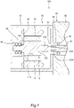
- FIG. 1 is a cross-sectional view of a part of a motor system 100 according to the first embodiment of the present disclosure.
- FIG. 2 is an enlarged view around a bearing 40.
- the motor system 100 (rotating electric machine system) includes a motor 50 and a transmission 60 and is, for example, a drive device for an electric vehicle.
- the motor system 100 of this embodiment is described as a drive device for an electric vehicle, the motor system 100 may be used as a drive device for an apparatus other than vehicles, for example, various electric equipment or industrial machines.
- the motor 50 rotates by receiving power from a power supply such as a battery (not shown) and functions as an electric motor that drives wheels of a vehicle.
- the motor 50 also functions as a generator that is driven by rotation of the wheels to generate (regenerate) electricity. Therefore, the motor 50 is a so-called motor generator (rotating electric machine) functioning as an electric motor and a generator.
- the motor 50 includes a rotor 10, a stator 20 surrounding the rotor 10, and a housing 30 accommodating the rotor 10 and the stator 20.
- the rotor 10 includes a cylindrical rotor core 11 formed by stacking plural electromagnetic steel sheets and including a permanent magnet therein, and a rotor shaft 12 fixed in an insertion hole 11A of the rotor core 11.
- the rotor 10 is rotatably disposed inside the stator 20.
- the rotor shaft 12 is a shaft member projecting from both end surfaces of the rotor core 11 to the outside in the axial direction.
- One end portion 121 (left end) of the rotor shaft 12 is rotatably supported by a bearing 40 fixed to the housing 30 and the other end portion 122 (right end) of the rotor shaft 12 is coupled to a rotation shaft 61 of the transmission 60. Rotation centers of the rotor shaft 12 and the rotation shaft 61 are located on the same line.
- the stator 20 is a cylindrical member formed by stacking plural electromagnetic steel sheets and is wound by U-phase, V-phase, and W-phase coils. An outer peripheral surface of the stator 20 is fixed to an inner peripheral surface of the housing 30.
- the housing 30 is a case member accommodating the rotor 10 and the stator 20 and is formed by casting a metal member, for example.
- the motor 50 and the transmission 60 are adjacent to each other.
- a right side surface of the housing 30 is fixed to a left side surface of a transmission case 62 of the transmission 60 by a fastening unit such as a bolt.
- a through hole 31 is formed in the right side surface of the housing 30, and allows the other end portion 122 of the rotor shaft 12 to pass through to the outside of the housing 30.
- the transmission 60 includes the rotation shaft 61 and plural gears (not shown) in the transmission case 62, and is a power transmission device that changes a speed of rotation power of the rotor shaft 12 and transmits the rotation power to the wheels.
- the rotation shaft 61 is rotatably supported by a ball bearing 63 provided in the transmission case 62.
- a through hole 64 is formed in the left side surface of the transmission case 62 and allows a left end portion (tip portion) of the rotation shaft 61 to pass through to the outside of the transmission case 62.
- the through hole 64 of the transmission case 62 communicates with the through hole 31 of the housing 30.
- the rotor shaft 12 of the motor 50 includes a center portion 123 fixed in the insertion hole 11A of the rotor core 11, the one end portion 121 extending from the center portion 123 to a side opposite to the transmission 60, and the other end portion 122 extending from the center portion 123 to the transmission 60.
- Outer diameters of the one end portion 121 and the other end portion 122 are smaller than an outer diameter of the center portion 123, and the one end portion 121 and the other end portion 122 are shaft members thinner than the center portion 123.
- the other end portion 122 of the rotor shaft 12 is a shaft member whose diameter decreases stepwise toward a tip.
- the rotation shaft 61 of the transmission 60 has a shaft hole 61A formed in a left end portion and recessed in the axial direction.
- the tip portion of the other end portion 122 of the rotor shaft 12 is inserted into the shaft hole 61A (spigot hole) formed in the end portion of the rotation shaft 61, and an outer peripheral surface of the other end portion 122 is fitted to an inner peripheral surface of the shaft hole 61A.
- the other end portion 122 of the rotor shaft 12 is connected to the rotation shaft 61 by a spigot joint structure that is fitted to the rotation shaft 61 of the transmission 60.
- the shaft hole 61A of the rotation shaft 61 is linearly formed in a portion constituting the left end portion of the rotation shaft 61
- the shaft hole 61A may be linearly formed from the left tip surface to the center portion 123 of the rotation shaft 61 or to a position closer to a right end portion than the center portion 123. Therefore, the other end portion 122 of the rotor shaft 12 may be spigot-connected to the shaft hole 61A of the rotation shaft 61 at the center portion 123 of the rotation shaft 61 or at a position closer to a right end than the center portion 123.
- the other end portion 122 of the rotor shaft 12 includes a spline portion 122A that is spline-coupled to the inner peripheral surface of the shaft hole 61A on an outer peripheral surface at a position closer to the center portion 123 than the tip, that is, at a position different from a portion (spigot connection portion) fitted to the rotation shaft 61. Relative rotation between the rotor shaft 12 and the rotation shaft 61 is restricted by spline-coupling the rotor shaft 12 and the rotation shaft 61 via the spline portion 122A.
- the spline portion 122A may be provided at a position close to the tip of the other end portion 122, and the portion (spigot connection portion) fitted to the rotation shaft 61 may be provided at a position closer to the center portion 123 than the spline portion 122A.
- a regulation of the relative rotation between the rotor shaft 12 and the rotation shaft 61 is implemented by a spline coupling structure and may also be implemented by coupling structures other than the spline coupling structure.
- the coupling structures other than the spline coupling structure include a flange coupling structure, an Oldham coupling structure, and a Latex coupling structure.
- a cylindrical bearing support portion 32 that supports the bearing 40 is formed in a projecting manner.
- the one end portion 121 of the rotor shaft 12 is rotatably supported by the bearing 40 fixed to an inner peripheral surface of the bearing support portion 32. In this way, when viewed in the motor 50 alone, the rotor shaft 12 of the rotor 10 is in a state where only the one end portion 121 is supported by the bearing 40.
- the bearing 40 is a double row angular contact ball bearing.
- the bearing 40 supporting the one end portion 121 of the rotor shaft 12 is a double row angular contact ball bearing, even when an axial force is applied to the rotor shaft 12, the rotor shaft 12 can rotate while receiving the force by the double row angular contact ball bearing. Thus, the rotor shaft 12 can be supported more stably.
- the rotor shaft 12 Before the motor 50 and the transmission 60 are assembled, the rotor shaft 12 is supported in a cantilever manner with respect to the housing 30 via the bearing 40. When the one end portion 121 of the rotor shaft 12 is not firmly supported by the bearing 40, the other end portion 122 of the rotor shaft 12 may swing, and the rotor core 11 attached to the rotor shaft 12 may interfere with the stator 20.
- the bearing 40 is a double row angular contact ball bearing, the one end portion 121 can be firmly supported without the other end portion 122 of the rotor shaft 12 swinging. Therefore, in a state before the rotor shaft 12 is coupled to the rotation shaft 61 of the transmission 60, it is possible to prevent interference between the rotor core 11 and the stator 20.
- the bearing 40 has a configuration in which two rows of rolling elements 43a and 43b are provided between an inner race 41 and an outer race 42 in the axial direction of the shaft, and in each row, a straight line (lines A and B) connecting contact points of the inner race 41, the rolling elements 43a and 43b, and the outer race 42 has an inclination with respect to a shaft radial direction.
- the line A in the outer row inclines toward the other end portion 122 from the inner race 41 toward the outer race 42, and the line B in the inner row inclines toward the one end portion 121 from the inner race 41 toward the outer race 42.
- the inner race 41 of the bearing 40 is fixed to an outer peripheral surface of the one end portion 121 of the rotor shaft 12.
- the outer race 42 of the bearing 40 is fixed to the inner peripheral surface of the bearing support portion 32.
- the diameter of the one end portion 121 of the rotor shaft 12 changes to decrease stepwise, and this stepped portion is referred to as a "step portion 124".
- a position of the bearing 40 in the axial direction is fixed by the step portion 124.
- a first wall-shaped member 201 is installed between a right end portion (hereinafter, referred to as a "first end portion 401") of the bearing 40 and the step portion 124.
- the first wall-shaped member 201 has an annular shape and is fixed by being fitted to the rotor shaft 12 and abutting against the step portion 124.
- the first wall-shaped member 201 has a wave spring shape, and is a spring member that exerts a biasing force by being compressed in a plate thickness direction.
- a second wall-shaped member 202 is installed on a side opposite to the first end portion 401 of the bearing 40, that is, on a left end portion (hereinafter, referred to as a "second end portion 402").
- the second wall-shaped member 202 has an annular shape, and is fixed to be not movable in the axial direction by being fitted to the rotor shaft 12 and further fitting a snap ring 204 into a groove 126 formed in the rotor shaft 12.
- the second wall-shaped member 202 may be fixed to the one end portion 121 of the rotor shaft 12 not by the snap ring 204 but by friction fit by press-fitting or the like, or may be fixed by screwing or the like.
- the inner race 41 of the bearing 40 is biased in the axial direction by the first wall-shaped member 201 that is a spring member, and is pressed toward the second wall-shaped member 202.
- the bearing 40 is sandwiched between the first wall-shaped member 201 and the second wall-shaped member 202, and the position of the bearing 40 is firmly fixed.
- Two O-rings 203a and 203b are interposed between the inner race 41 of the bearing 40 and the one end portion 121 of the rotor shaft 12.
- two grooves 125a and 125b are circumferentially formed in parallel in the axial direction on an outer periphery of the one end portion 121.
- the O-rings 203a and 203b are fitted in parallel in the grooves 125a and 125b, respectively.
- Each of the O-rings 203a and 203b is formed of an elastic member such as rubber and has an annular shape and a substantially circular cross section. A diameter of the cross section is larger than a depth of each of the grooves 125a and 125b.
- portions where the O-rings 203a and 203b are fitted have a diameter larger than the diameter of the outer periphery of the one end portion 121.
- An inner diameter of the inner race 41 of the bearing 40 is slightly larger than the diameter of the outer periphery of the one end portion 121.
- the inner race 41 of the bearing 40 crushes the O-rings 203a and 203b, and an inner periphery of the inner race 41 of the bearing 40 is supported by an elastic force of the O-rings 203a and 203b provided in parallel in the axial direction at a position slightly separated from the outer periphery of the one end portion 121.
- grease which is a viscous fluid
- the grease is filled in a space formed between the first wall-shaped member 201 and the second wall-shaped member 202, which is a gap between the inner periphery of the inner race 41 of the bearing 40 and the outer periphery of the one end portion 121.
- the configuration in which the bearing 40 is attached to the rotor shaft 12 via the O-rings 203a and 203b cushions a vibration of the rotor shaft 12 from being transmitted to the bearing 40. Furthermore, since the grease is filled between the bearing 40 and the rotor shaft 12, the inner periphery of the inner race 41 of the bearing 40 and the outer periphery of the one end portion 121 of the rotor shaft 12 are prevented from coming into contact with each other and thus the wear is prevented.
- the bearing 40 is supported by the two O-rings 203a and 203b, and is not limited thereto.
- a flat belt-shaped elastic member may be interposed between the bearing 40 and the one end portion 121 without providing a groove in the one end portion 121.
- the O-rings 203a and 203b may be made of an elastic member such as silicon or elastomer instead of rubber.
- first wall-shaped member 201 may be configured with another spring such as a disc spring instead of the wave spring.
- first wall-shaped member 201 may be formed of an elastic material such as rubber.
- the second wall-shaped member 202 may be configured with a spring member, and both the first wall-shaped member 201 and the second wall-shaped member 202 may be spring members. In this embodiment, in consideration of prevention of grease scattering, it is preferable that only the first wall-shaped member 201 in contact with the step portion 124 is a spring member.
- the O-rings 203a and 203b are fitted in the grooves 125a and 125b of the one end portion 121 of the rotor shaft 12, respectively.
- the first wall-shaped member 201 is axially passed through an open end of the one end portion 121 of the rotor shaft 12. The first wall-shaped member 201 is moved until the first wall-shaped member 201 abuts against the step portion 124.
- the bearing 40 is axially passed through the rotor shaft 12 from the open end of the one end portion 121 of the rotor shaft 12.
- the bearing 40 is moved to a position where the bearing 40 abuts against the first wall-shaped member 201.
- the second wall-shaped member 202 is axially passed through the rotor shaft 12 from the open end of the one end portion 121 of the rotor shaft 12, and is moved to a position where the second wall-shaped member 202 abuts against the second end portion 402 of the bearing 40. In this state, the snap ring 204 is fitted in the groove 126.
- the bearing 40 is attached to the one end portion 121 of the rotor shaft 12. Thereafter, when the rotor shaft 12 is attached to the housing 30, the outer race 42 of the bearing 40 is fixed to the bearing support portion 32 of the housing 30 by press-fitting or the like. Thus, the bearing 40 is fixed to the housing 30, and the rotor shaft 12 is supported.
- the motor 50 includes the rotor 10 and the stator 20 in the housing 30.
- the rotor shaft 12 of the rotor 10 is connected to the rotation shaft 61 (power transmission shaft) of the transmission 60 (power transmission device).
- the bearing 40 is provided in the housing 30.
- the one end portion 121 of the rotor shaft 12 is supported by the bearing 40, and the other end portion 122 of the rotor shaft 12 is supported by the rotation shaft 61 by the spigot joint structure fitted to the rotation shaft 61.
- the O-rings 203a and 203b are provided between the bearing 40 and the rotor shaft 12.
- the O-rings 203a and 203b elastic members
- the vibration of the rotor shaft 12, which is transmitted to the bearing 40, due to the spigot joint structure of the other end portion 122 is cushioned, the bearing 40 and the rotor shaft 12 can be prevented from being worn or damaged, and the durability of the bearing 40 can be ensured.
- the elastic members are the O-rings 203a and 203b fixed to the rotor shaft 12, it is possible to prevent wear or damage of the bearing 40 and the rotor shaft 12 by a simple and inexpensive configuration.
- the two O-rings 203a and 203b are provided in parallel in the axial direction between the bearing 40 and the rotor shaft 12, it is possible to more reliably prevent the wear or damage of the bearing 40 and the rotor shaft 12.
- the gap formed between the bearing 40 and the rotor shaft 12 by the O-rings 203a and 203b is filled with the grease that is a viscous fluid, the inner periphery of the inner race 41 of the bearing 40 and the outer periphery of the one end portion 121 of the rotor shaft 12 are prevented from coming into contact with each other, and the wear is further prevented.
- the bearing 40 is a double row angular contact ball bearing, even when the axial force is applied to the rotor shaft 12, the rotor shaft 12 can receive the force by the double row angular contact ball bearing. Thus, the rotor shaft 12 can be supported more stably.
- the rotor shaft 12 is provided with the wall-shaped members (the first wall-shaped member 201 and the second wall-shaped member 202) that restrict movement of the bearing 40 in the axial direction at both ends of the bearing 40, the position of the bearing 40 on the rotor shaft 12 is fixed between the first wall-shaped member 201 and the second wall-shaped member 202.
- the bearing 40 since at least one (the first wall-shaped member 201) of the wall-shaped members (the first wall-shaped member 201 and the second wall-shaped member 202) is a spring member that biases the bearing 40 in the axial direction, the bearing 40 is biased by the first wall-shaped member 201 that is a spring member and is pressed toward the second wall-shaped member 202. As a result, the position of the bearing 40 on the rotor shaft 12 is firmly fixed between the first wall-shaped member 201 and the second wall-shaped member 202. Furthermore, the grease filled between the bearing 40 and the rotor shaft 12 is prevented from scattering to the outside by sandwiching the bearing 40 between the first wall-shaped member 201 and the second wall-shaped member 202.
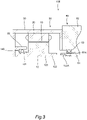
- the motor 50 of the second embodiment is different from the motor 50 of the first embodiment in a configuration of a bearing.
- the motor 50 includes a bearing 140 configured with a single row ball bearing (deep groove ball bearing) instead of the bearing 40 configured with a double row angular contact ball bearing.
- a bearing 140 configured with a single row ball bearing (deep groove ball bearing) instead of the bearing 40 configured with a double row angular contact ball bearing.
- Other configurations are the same as those of the first embodiment described above, and thus the description thereof will be omitted.
- the double row angular contact ball bearing can rotate while receiving loads in both an axial direction (thrust direction) and a radial direction, whereas the single row ball bearing has a simple configuration and is inexpensive, and is characterized by receiving a load mainly in the radial direction.
- the bearing 140 that is a single row ball bearing can be adopted in consideration of the load between the motor 50 and the transmission 60, the configuration of a spigot joint, and the like.
- the manufacturing cost and maintenance cost of the motor system 100 can be reduced.
- the motor 50 of the third embodiment is different from the motor 50 of the first embodiment in a way of spigot connection between the other end portion 122 of the rotor shaft 12 and the rotation shaft 61 of the transmission 60.
- a shaft hole 122B (spigot hole) recessed in the axial direction is formed in a tip portion of the other end portion 122 of the rotor shaft 12.
- a left end portion of the rotation shaft 61 of the transmission 60 is a shaft member whose diameter decreases stepwise toward a tip.
- the left end portion (tip portion) of the rotation shaft 61 of the transmission 60 is inserted into the shaft hole 122B, and an inner peripheral surface of the shaft hole 122B located close to a tip surface of the other end portion 122 is fitted to an outer peripheral surface of an end portion of the rotation shaft 61.
- Other configurations are the same as those of the first embodiment described above, and thus the description thereof will be omitted.
- the shaft hole 122B formed in the other end portion 122 of the rotor shaft 12 includes a spline portion 122C that is spline-coupled to the outer peripheral surface of the rotation shaft 61 on an inner peripheral surface at a position closer to the center portion 123 than the tip, that is, at a position different from a portion (spigot connection portion) fitted to the rotation shaft 61. Relative rotation between the rotor shaft 12 and the rotation shaft 61 is restricted by spline-coupling the rotor shaft 12 and the rotation shaft 61 with the spline portion 122C.
- the spline portion 122C may be provided at a position close to the tip of the other end portion 122, and the portion (spigot connection portion) fitted to the rotation shaft 61 may be provided at a position closer to the center portion 123 than to the spline portion 122C.
- the other end portion 122 of the rotor shaft 12 is connected to the rotation shaft 61 by a spigot joint structure fitted to the rotation shaft 61 of the transmission 60.
- the shaft hole 122B of the rotor shaft 12 is linearly formed in a portion constituting the other end portion 122, the shaft hole 122B may be linearly formed from a right tip surface to the center portion 123 of the rotor shaft 12 or to a position closer to the one end portion 121 than the center portion 123. Therefore, the rotor shaft 12 may be spigot-connected to the rotation shaft 61 of the transmission 60 at the center portion 123 or at the position closer to the one end portion 121 than the center portion 123.
- a regulation of the relative rotation between the rotor shaft 12 and the rotation shaft 61 may be implemented by coupling structures other than the spline coupling structure.
- the coupling structures other than the spline coupling structure include a flange coupling structure, an Oldham coupling structure, and a Rotex coupling structure.
- the other end portion 122 of the rotor shaft 12 since the other end portion 122 of the rotor shaft 12 is inserted into the shaft hole 61A of the rotation shaft 61, a shaft thickness of the rotor shaft 12 cannot be made larger than a shaft thickness of the rotation shaft 61.
- the motor 50 of this embodiment has a configuration in which the shaft hole 122B of the other end portion 122 of the rotor shaft 12 is externally fitted to the end portion of the rotation shaft 61, the other end portion 122 can have any thickness regardless of the shaft thickness of the rotation shaft 61. As a result, connection strength between the other end portion 122 of the rotor shaft 12 and the rotation shaft 61 of the transmission 60 can be increased, as necessary.
- the other end portion 122 can be easily have any thickness within a range in which an outer diameter of the other end portion 122 is not larger than an outer diameter of the center portion 123.
- the other end portion 122 and the center portion 123 of the rotor shaft 12 have the same outer diameter, only the one end portion 121 needs to have a smaller diameter than other portions, and the manufacturing cost of the rotor shaft 12 can be reduced.
- the manufacturing cost increases in a case where only the end portion of the rotation shaft 61 having a substantially constant outer diameter is thick as in the first embodiment in order to increase the connection strength. Therefore, according to the rotor shaft 12 of this embodiment, it is possible to increase the connection strength between the rotor shaft 12 and the rotation shaft 61 without increasing the manufacturing cost.
- the shaft hole 122B of the other end portion 122 of the rotor shaft 12 includes the spline portion 122C that is spline-coupled to the outer peripheral surface of the rotation shaft 61 on the inner peripheral surface at the position different from the portion fitted to the rotation shaft 61.
- the other end portion 122 of the rotor shaft 12 is formed with a portion that is spigot-connected to the rotation shaft 61 and a portion that is spline-coupled to the rotation shaft 61. Therefore, a connection range of the rotor shaft 12 to the rotation shaft 61 is widened, and the other end portion 122 of the rotor shaft 12 can be supported more stably.
- a portion to be fitted to the rotation shaft 61 is provided at a position closer to the rotation shaft 61 than the spline portion 122C, for example, in the shaft hole 122B in the tip portion of the other end portion 122.
- a portion supported by the bearing 40 and a portion supported by the rotation shaft 61 can be disposed as far as possible.
- the fourth embodiment is different from the first embodiment in a structure supporting the rotor core 11.
- the rotor 10 of the motor 50 includes the rotor core 11, the rotor shaft 12, a core support portion 13, and a connection portion 14.
- Other configurations are the same as those of the first embodiment described above, and thus the description thereof will be omitted.
- the core support portion 13 of the rotor 10 has a cylindrical shape and is a member that supports the cylindrical rotor core 11 from the inside.
- the core support portion 13 is formed such that an axial length thereof is slightly larger than an axial length of the rotor core 11.
- the core support portion 13 is inserted into the insertion hole 11A of the rotor core 11, and the rotor core 11 is fixed onto the core support portion 13 in a state of being externally fitted to an outer periphery of the core support portion 13.
- the rotor shaft 12 is disposed inside the core support portion 13.
- the rotor shaft 12 and the core support portion 13 are connected to each other by the connection portion 14.
- the connection portion 14 is a plate-shaped wall portion projecting from an outer peripheral surface of the center portion 123 of the rotor shaft 12 in a radial direction of the rotor shaft, and couples the outer peripheral surface of the center portion 123 of the rotor shaft 12 to an inner peripheral surface of the core support portion 13.
- a plate thickness of the connection portion 14 is thinner than axial lengths of the rotor shaft 12 and the core support portion 13.
- the one end portion 121 is supported by the bearing 40, and the other end portion 122 is spigot-connected to the rotation shaft 61 of the transmission 60 in a state where the other end portion 122 circumscribes an end portion of the rotation shaft 61.
- the other end portion 122 of the rotor shaft 12 is a spigot joint structure in which a tip portion of the rotation shaft 61 is inserted into the shaft hole 122B of the other end portion 122 of the rotor shaft 12, and may also be a spigot joint structure in which the tip portion of the other end portion 122 of the rotor shaft 12 is inserted into the shaft hole 61A of the rotation shaft 61, as in the first embodiment shown in FIG. 1 .
- the housing 30 is formed by a left housing 30L and a right housing 30R, and a center portion 33 of the left housing 30L is recessed in the axial direction of the shaft to enter the inside of the core support portion 13.
- the bearing support portion 32 is formed on the center portion 33 of the left housing 30L, and the bearing 40 is fixed to the bearing support portion 32. That is, the bearing 40 is provided and fixed to the center portion 33 of the left housing 30L to be located inside the rotor core 11 and the core support portion 13.
- the bearing 40 is a double row angular contact ball bearing.
- the one end portion 121 of the rotor shaft 12 and the bearing 40 are fixed in the same manner as that of the first embodiment described above. That is, on the first end portion 401 side of the bearing 40, the first wall-shaped member 201 that is a spring member is fixed to the step portion 124 formed in a vicinity of a boundary between the connection portion 14 connecting the rotor shaft 12 and the core support portion 13 and the one end portion 121, and the second end portion 402 of the bearing 40 is fixed by the second wall-shaped member.
- the O-rings 203a and 203b are interposed between an inner peripheral side of the inner race 41 of the bearing 40 and an outer peripheral side of the one end portion 121 of the rotor shaft 12, and grease is filled therein.
- connection portion 14 Instead of pressing and fixing the first wall-shaped member 201 to the step portion 124 formed in the vicinity of the boundary between the connection portion 14 and the one end portion 121, the connection portion 14 extends in a vertical direction from the one end portion 121, and the first wall-shaped member 201 is pressed to the connection portion 14.
- the rotor 10 includes the core support portion 13 that supports the rotor core 11 from the inside, and the connection portion 14 that is a plate-shaped member projecting in a radial direction of the rotor shaft from the outer peripheral surface of the rotor shaft 12 and couples the outer peripheral surface of the rotor shaft 12 to the inner peripheral surface of the core support portion 13. Furthermore, the left housing 30L constituting the housing 30 is formed such that the center portion 33 (portion) enters the inside of the core support portion 13.
- the first wall-shaped member 201 that is a spring member that biases the bearing 40 in the axial direction is provided between the connection portion 14 and the first end portion 401 (one end side) of the bearing 40, and the second wall-shaped member 202 that restricts movement of the bearing in the axial direction is provided at the second end portion 402 (the other end side) of the bearing 40.
- the motor 50 since the one end portion 121 of the rotor shaft 12 is supported by the bearing 40 provided in the portion entering the inside of the core support portion 13, a width of the motor 50 itself in the axial direction can be made smaller than a width of the motor 50 of other embodiments. As a result, the motor 50 can be made compact. Furthermore, since the bearing 40 is fixed to abut against the connection portion 14, it is possible to prevent the grease from scattering.
- the rotor core 11, the stator 20, the core support portion 13, and the like described in the above embodiments are cylindrical members, and may also be polygonal tubular members.
- the motor 50 is assembled to the transmission 60 that is a power transmission device, and the motor 50 may also be assembled to power transmission devices such as a decelerator. Also in this case, the rotor shaft 12 of the motor 50 and a rotation shaft of the decelerator can be coupled by applying the technical idea in the embodiments.
Landscapes
- Engineering & Computer Science (AREA)
- Power Engineering (AREA)
- Motor Or Generator Frames (AREA)
- Support Of The Bearing (AREA)
- Mounting Of Bearings Or Others (AREA)
- Rolling Contact Bearings (AREA)
- Connection Of Motors, Electrical Generators, Mechanical Devices, And The Like (AREA)
Abstract
Description
- The present invention relates to a rotating electric machine.
-
JP2014-225971A - In the above electric motor, a ball bearing supporting the one end of the rotor shaft and a ball bearing supporting the other end of the rotor shaft are provided in the motor housing. That is, the electric motor has a configuration in which the rotor shaft is rotatably borne by the ball bearing on one end side and the ball bearing on the other end side, and the two ball bearings are disposed apart from each other in an axial direction of the shaft. In the electric motor (rotating electric machine) having such a configuration, since the ball bearings are disposed on the one end side and the other end side of the rotor shaft, there is a problem that not only the overall configuration of the electric motor is complicated, but also friction loss due to the ball bearings on the one end side and the other end side occurs at the time of driving the motor.
- To solve such a problem, a configuration is also conceivable in which only the one end side of the rotor shaft is supported by a ball bearing and the other end side is connected to a rotation shaft of a transmission by a spline or the like. With such a configuration, although the friction loss can be reduced, vibration generated between the rotor shaft and the rotation shaft is transmitted to the bearing, which causes a problem in ensuring durability of the bearing.
- An object of the present invention is to provide a rotating electric machine capable of ensuring durability of a bearing while reducing friction loss with a simple configuration.
- According to an aspect of the present invention, a rotating electric machine including a rotor and a stator in a housing, the rotor having a rotor shaft connected to a power transmission shaft of a power transmission device, is providing, a bearing is provided in the housing, one end portion of the rotor shaft is supported by the bearing, the other end portion of the rotor shaft is supported by the power transmission shaft with a spigot joint structure fitted to the power transmission shaft, and an elastic member is provided between the bearing and the rotor shaft.
-
-
FIG. 1 is a vertical cross-sectional view of a part of a motor system according to a first embodiment. -
FIG. 2 is an enlarged view around a bearing. -
FIG. 3 is a vertical cross-sectional of a part of a motor system according to a second embodiment. -
FIG. 4 is a vertical cross-sectional of a part of a motor system according to a third embodiment. -
FIG. 5 is a vertical cross-sectional of a part of a motor system according to a fourth embodiment. - Hereinafter, embodiments of the present disclosure are described with reference to the drawings.
-
FIG. 1 is a cross-sectional view of a part of amotor system 100 according to the first embodiment of the present disclosure.FIG. 2 is an enlarged view around abearing 40. - As shown in
FIG. 1 , the motor system 100 (rotating electric machine system) includes amotor 50 and atransmission 60 and is, for example, a drive device for an electric vehicle. Although themotor system 100 of this embodiment is described as a drive device for an electric vehicle, themotor system 100 may be used as a drive device for an apparatus other than vehicles, for example, various electric equipment or industrial machines. - The
motor 50 rotates by receiving power from a power supply such as a battery (not shown) and functions as an electric motor that drives wheels of a vehicle. Themotor 50 also functions as a generator that is driven by rotation of the wheels to generate (regenerate) electricity. Therefore, themotor 50 is a so-called motor generator (rotating electric machine) functioning as an electric motor and a generator. - The
motor 50 includes arotor 10, astator 20 surrounding therotor 10, and ahousing 30 accommodating therotor 10 and thestator 20. - The
rotor 10 includes acylindrical rotor core 11 formed by stacking plural electromagnetic steel sheets and including a permanent magnet therein, and arotor shaft 12 fixed in aninsertion hole 11A of therotor core 11. Therotor 10 is rotatably disposed inside thestator 20. Therotor shaft 12 is a shaft member projecting from both end surfaces of therotor core 11 to the outside in the axial direction. One end portion 121 (left end) of therotor shaft 12 is rotatably supported by abearing 40 fixed to thehousing 30 and the other end portion 122 (right end) of therotor shaft 12 is coupled to arotation shaft 61 of thetransmission 60. Rotation centers of therotor shaft 12 and therotation shaft 61 are located on the same line. - The
stator 20 is a cylindrical member formed by stacking plural electromagnetic steel sheets and is wound by U-phase, V-phase, and W-phase coils. An outer peripheral surface of thestator 20 is fixed to an inner peripheral surface of thehousing 30. - The
housing 30 is a case member accommodating therotor 10 and thestator 20 and is formed by casting a metal member, for example. Themotor 50 and thetransmission 60 are adjacent to each other. A right side surface of thehousing 30 is fixed to a left side surface of atransmission case 62 of thetransmission 60 by a fastening unit such as a bolt. - In the right side surface of the
housing 30, athrough hole 31 is formed and allows theother end portion 122 of therotor shaft 12 to pass through to the outside of thehousing 30. - The
transmission 60 includes therotation shaft 61 and plural gears (not shown) in thetransmission case 62, and is a power transmission device that changes a speed of rotation power of therotor shaft 12 and transmits the rotation power to the wheels. Therotation shaft 61 is rotatably supported by a ball bearing 63 provided in thetransmission case 62. - In the left side surface of the
transmission case 62, athrough hole 64 is formed and allows a left end portion (tip portion) of therotation shaft 61 to pass through to the outside of thetransmission case 62. The throughhole 64 of thetransmission case 62 communicates with the throughhole 31 of thehousing 30. - Next, a support structure of the
rotor shaft 12 of themotor 50 will be described. - As shown in
FIG. 1 , therotor shaft 12 of themotor 50 includes acenter portion 123 fixed in theinsertion hole 11A of therotor core 11, the oneend portion 121 extending from thecenter portion 123 to a side opposite to thetransmission 60, and theother end portion 122 extending from thecenter portion 123 to thetransmission 60. Outer diameters of the oneend portion 121 and theother end portion 122 are smaller than an outer diameter of thecenter portion 123, and the oneend portion 121 and theother end portion 122 are shaft members thinner than thecenter portion 123. - The
other end portion 122 of therotor shaft 12 is a shaft member whose diameter decreases stepwise toward a tip. Therotation shaft 61 of thetransmission 60 has ashaft hole 61A formed in a left end portion and recessed in the axial direction. The tip portion of theother end portion 122 of therotor shaft 12 is inserted into theshaft hole 61A (spigot hole) formed in the end portion of therotation shaft 61, and an outer peripheral surface of theother end portion 122 is fitted to an inner peripheral surface of theshaft hole 61A. In this way, theother end portion 122 of therotor shaft 12 is connected to therotation shaft 61 by a spigot joint structure that is fitted to therotation shaft 61 of thetransmission 60. - Although the
shaft hole 61A of therotation shaft 61 is linearly formed in a portion constituting the left end portion of therotation shaft 61, theshaft hole 61A may be linearly formed from the left tip surface to thecenter portion 123 of therotation shaft 61 or to a position closer to a right end portion than thecenter portion 123. Therefore, theother end portion 122 of therotor shaft 12 may be spigot-connected to theshaft hole 61A of therotation shaft 61 at thecenter portion 123 of therotation shaft 61 or at a position closer to a right end than thecenter portion 123. - The
other end portion 122 of therotor shaft 12 includes aspline portion 122A that is spline-coupled to the inner peripheral surface of theshaft hole 61A on an outer peripheral surface at a position closer to thecenter portion 123 than the tip, that is, at a position different from a portion (spigot connection portion) fitted to therotation shaft 61. Relative rotation between therotor shaft 12 and therotation shaft 61 is restricted by spline-coupling therotor shaft 12 and therotation shaft 61 via thespline portion 122A. - In the
rotor shaft 12, thespline portion 122A may be provided at a position close to the tip of theother end portion 122, and the portion (spigot connection portion) fitted to therotation shaft 61 may be provided at a position closer to thecenter portion 123 than thespline portion 122A. - Further, in this embodiment, a regulation of the relative rotation between the
rotor shaft 12 and therotation shaft 61 is implemented by a spline coupling structure and may also be implemented by coupling structures other than the spline coupling structure. Examples of the coupling structures other than the spline coupling structure include a flange coupling structure, an Oldham coupling structure, and a Latex coupling structure. - On an inner side of a left side surface of the
housing 30, a cylindricalbearing support portion 32 that supports thebearing 40 is formed in a projecting manner. The oneend portion 121 of therotor shaft 12 is rotatably supported by the bearing 40 fixed to an inner peripheral surface of thebearing support portion 32. In this way, when viewed in themotor 50 alone, therotor shaft 12 of therotor 10 is in a state where only the oneend portion 121 is supported by thebearing 40. The bearing 40 is a double row angular contact ball bearing. - Since the
bearing 40 supporting the oneend portion 121 of therotor shaft 12 is a double row angular contact ball bearing, even when an axial force is applied to therotor shaft 12, therotor shaft 12 can rotate while receiving the force by the double row angular contact ball bearing. Thus, therotor shaft 12 can be supported more stably. - Before the
motor 50 and thetransmission 60 are assembled, therotor shaft 12 is supported in a cantilever manner with respect to thehousing 30 via thebearing 40. When the oneend portion 121 of therotor shaft 12 is not firmly supported by thebearing 40, theother end portion 122 of therotor shaft 12 may swing, and therotor core 11 attached to therotor shaft 12 may interfere with thestator 20. - However, in the
motor 50 of this embodiment, since thebearing 40 is a double row angular contact ball bearing, the oneend portion 121 can be firmly supported without theother end portion 122 of therotor shaft 12 swinging. Therefore, in a state before therotor shaft 12 is coupled to therotation shaft 61 of thetransmission 60, it is possible to prevent interference between therotor core 11 and thestator 20. - Next, details of the
bearing 40 will be described with reference toFIG. 2 . - The
bearing 40 has a configuration in which two rows of rollingelements inner race 41 and anouter race 42 in the axial direction of the shaft, and in each row, a straight line (lines A and B) connecting contact points of theinner race 41, the rollingelements outer race 42 has an inclination with respect to a shaft radial direction. The line A in the outer row inclines toward theother end portion 122 from theinner race 41 toward theouter race 42, and the line B in the inner row inclines toward the oneend portion 121 from theinner race 41 toward theouter race 42. - The
inner race 41 of thebearing 40 is fixed to an outer peripheral surface of the oneend portion 121 of therotor shaft 12. Theouter race 42 of thebearing 40 is fixed to the inner peripheral surface of thebearing support portion 32. - The diameter of the one
end portion 121 of therotor shaft 12 changes to decrease stepwise, and this stepped portion is referred to as a "step portion 124". A position of the bearing 40 in the axial direction is fixed by thestep portion 124. - More specifically, a first wall-shaped
member 201 is installed between a right end portion (hereinafter, referred to as a "first end portion 401") of thebearing 40 and thestep portion 124. The first wall-shapedmember 201 has an annular shape and is fixed by being fitted to therotor shaft 12 and abutting against thestep portion 124. The first wall-shapedmember 201 has a wave spring shape, and is a spring member that exerts a biasing force by being compressed in a plate thickness direction. - A second wall-shaped
member 202 is installed on a side opposite to thefirst end portion 401 of thebearing 40, that is, on a left end portion (hereinafter, referred to as a "second end portion 402"). The second wall-shapedmember 202 has an annular shape, and is fixed to be not movable in the axial direction by being fitted to therotor shaft 12 and further fitting asnap ring 204 into agroove 126 formed in therotor shaft 12. The second wall-shapedmember 202 may be fixed to the oneend portion 121 of therotor shaft 12 not by thesnap ring 204 but by friction fit by press-fitting or the like, or may be fixed by screwing or the like. - Since the first wall-shaped
member 201 is a spring member and the second wall-shapedmember 202 is not movable, theinner race 41 of thebearing 40 is biased in the axial direction by the first wall-shapedmember 201 that is a spring member, and is pressed toward the second wall-shapedmember 202. As a result, thebearing 40 is sandwiched between the first wall-shapedmember 201 and the second wall-shapedmember 202, and the position of thebearing 40 is firmly fixed. - Two O-
rings inner race 41 of thebearing 40 and the oneend portion 121 of therotor shaft 12. - More specifically, two
grooves end portion 121. The O-rings grooves rings grooves - That is, in a state where the O-
rings grooves rings end portion 121. An inner diameter of theinner race 41 of thebearing 40 is slightly larger than the diameter of the outer periphery of the oneend portion 121. When thebearing 40 is attached to the oneend portion 121 of therotor shaft 12, theinner race 41 of thebearing 40 crushes the O-rings inner race 41 of thebearing 40 is supported by an elastic force of the O-rings end portion 121. - Furthermore, grease, which is a viscous fluid, is filled between the
inner race 41 of thebearing 40 and the oneend portion 121. That is, the grease is filled in a space formed between the first wall-shapedmember 201 and the second wall-shapedmember 202, which is a gap between the inner periphery of theinner race 41 of thebearing 40 and the outer periphery of the oneend portion 121. - In this way, the configuration in which the
bearing 40 is attached to therotor shaft 12 via the O-rings rotor shaft 12 from being transmitted to thebearing 40. Furthermore, since the grease is filled between the bearing 40 and therotor shaft 12, the inner periphery of theinner race 41 of thebearing 40 and the outer periphery of the oneend portion 121 of therotor shaft 12 are prevented from coming into contact with each other and thus the wear is prevented. - The
bearing 40 is supported by the two O-rings end portion 121 without providing a groove in the oneend portion 121. The O-rings - In addition, the first wall-shaped
member 201 may be configured with another spring such as a disc spring instead of the wave spring. Further, the first wall-shapedmember 201 may be formed of an elastic material such as rubber. Instead of the first wall-shapedmember 201, the second wall-shapedmember 202 may be configured with a spring member, and both the first wall-shapedmember 201 and the second wall-shapedmember 202 may be spring members. In this embodiment, in consideration of prevention of grease scattering, it is preferable that only the first wall-shapedmember 201 in contact with thestep portion 124 is a spring member. - Next, a method for attaching the
bearing 40 to therotor shaft 12 of the first embodiment will be described. - First, the O-
rings grooves end portion 121 of therotor shaft 12, respectively. - Next, the first wall-shaped
member 201 is axially passed through an open end of the oneend portion 121 of therotor shaft 12. The first wall-shapedmember 201 is moved until the first wall-shapedmember 201 abuts against thestep portion 124. - Next, the grease is applied around the O-
rings end portion 121 of therotor shaft 12. - Next, the
bearing 40 is axially passed through therotor shaft 12 from the open end of the oneend portion 121 of therotor shaft 12. Thebearing 40 is moved to a position where thebearing 40 abuts against the first wall-shapedmember 201. - Next, the second wall-shaped
member 202 is axially passed through therotor shaft 12 from the open end of the oneend portion 121 of therotor shaft 12, and is moved to a position where the second wall-shapedmember 202 abuts against thesecond end portion 402 of thebearing 40. In this state, thesnap ring 204 is fitted in thegroove 126. - In this way, the
bearing 40 is attached to the oneend portion 121 of therotor shaft 12. Thereafter, when therotor shaft 12 is attached to thehousing 30, theouter race 42 of thebearing 40 is fixed to thebearing support portion 32 of thehousing 30 by press-fitting or the like. Thus, thebearing 40 is fixed to thehousing 30, and therotor shaft 12 is supported. - According to the motor 50 (rotating electric machine) of the first embodiment of the present disclosure described above, the following operational effects can be obtained.
- The
motor 50 according to this embodiment includes therotor 10 and thestator 20 in thehousing 30. Therotor shaft 12 of therotor 10 is connected to the rotation shaft 61 (power transmission shaft) of the transmission 60 (power transmission device). Thebearing 40 is provided in thehousing 30. The oneend portion 121 of therotor shaft 12 is supported by thebearing 40, and theother end portion 122 of therotor shaft 12 is supported by therotation shaft 61 by the spigot joint structure fitted to therotation shaft 61. Further, the O-rings rotor shaft 12. - In this embodiment, since the
other end portion 122 of therotor shaft 12 is spigot-connected to therotation shaft 61 of thetransmission 60, it is not necessary to provide a bearing for supporting theother end portion 122 of therotor shaft 12 in thehousing 30. In themotor 50, since both ends of therotor shaft 12 can be rotatably supported by the bearing 40 for the oneend portion 121 provided in thehousing 30 and therotation shaft 61 of thetransmission 60, it is possible to omit a bearing for theother end portion 122 of therotor shaft 12. As a result, the overall configuration of themotor 50 can be simplified. In addition, since no bearing is disposed at theother end portion 122, it is possible to reduce the frictional resistance during rotation of therotor shaft 12, and to reduce the manufacturing cost of themotor 50. - Furthermore, since the O-
rings rotor shaft 12, the vibration of therotor shaft 12, which is transmitted to thebearing 40, due to the spigot joint structure of theother end portion 122 is cushioned, thebearing 40 and therotor shaft 12 can be prevented from being worn or damaged, and the durability of thebearing 40 can be ensured. - In the
motor 50 according to this embodiment, since the elastic members are the O-rings rotor shaft 12, it is possible to prevent wear or damage of thebearing 40 and therotor shaft 12 by a simple and inexpensive configuration. - In the
motor 50 according to this embodiment, since the two O-rings rotor shaft 12, it is possible to more reliably prevent the wear or damage of thebearing 40 and therotor shaft 12. - In the
motor 50 according to this embodiment, since the gap formed between the bearing 40 and therotor shaft 12 by the O-rings inner race 41 of thebearing 40 and the outer periphery of the oneend portion 121 of therotor shaft 12 are prevented from coming into contact with each other, and the wear is further prevented. - In the
motor 50 according to this embodiment, since thebearing 40 is a double row angular contact ball bearing, even when the axial force is applied to therotor shaft 12, therotor shaft 12 can receive the force by the double row angular contact ball bearing. Thus, therotor shaft 12 can be supported more stably. - In the
motor 50 according to this embodiment, since therotor shaft 12 is provided with the wall-shaped members (the first wall-shapedmember 201 and the second wall-shaped member 202) that restrict movement of the bearing 40 in the axial direction at both ends of thebearing 40, the position of the bearing 40 on therotor shaft 12 is fixed between the first wall-shapedmember 201 and the second wall-shapedmember 202. - In the
motor 50 according to this embodiment, since at least one (the first wall-shaped member 201) of the wall-shaped members (the first wall-shapedmember 201 and the second wall-shaped member 202) is a spring member that biases thebearing 40 in the axial direction, thebearing 40 is biased by the first wall-shapedmember 201 that is a spring member and is pressed toward the second wall-shapedmember 202. As a result, the position of the bearing 40 on therotor shaft 12 is firmly fixed between the first wall-shapedmember 201 and the second wall-shapedmember 202. Furthermore, the grease filled between the bearing 40 and therotor shaft 12 is prevented from scattering to the outside by sandwiching thebearing 40 between the first wall-shapedmember 201 and the second wall-shapedmember 202. - Next, the
motor system 100 provided with themotor 50 and thetransmission 60 according to a second embodiment of the present embodiment will be described with reference toFIG. 3 . Themotor 50 of the second embodiment is different from themotor 50 of the first embodiment in a configuration of a bearing. - As shown in
FIG. 3 , themotor 50 according to this embodiment includes abearing 140 configured with a single row ball bearing (deep groove ball bearing) instead of the bearing 40 configured with a double row angular contact ball bearing. Other configurations are the same as those of the first embodiment described above, and thus the description thereof will be omitted. - The double row angular contact ball bearing can rotate while receiving loads in both an axial direction (thrust direction) and a radial direction, whereas the single row ball bearing has a simple configuration and is inexpensive, and is characterized by receiving a load mainly in the radial direction.
- Therefore, in the
motor system 100, the bearing 140 that is a single row ball bearing can be adopted in consideration of the load between themotor 50 and thetransmission 60, the configuration of a spigot joint, and the like. Thus, the manufacturing cost and maintenance cost of themotor system 100 can be reduced. - Next, the
motor system 100 provided with themotor 50 and thetransmission 60 according to a third embodiment of the present embodiment will be described with reference toFIG. 4 . Themotor 50 of the third embodiment is different from themotor 50 of the first embodiment in a way of spigot connection between theother end portion 122 of therotor shaft 12 and therotation shaft 61 of thetransmission 60. - As shown in
FIG. 4 , in themotor 50 according to this embodiment, ashaft hole 122B (spigot hole) recessed in the axial direction is formed in a tip portion of theother end portion 122 of therotor shaft 12. A left end portion of therotation shaft 61 of thetransmission 60 is a shaft member whose diameter decreases stepwise toward a tip. The left end portion (tip portion) of therotation shaft 61 of thetransmission 60 is inserted into theshaft hole 122B, and an inner peripheral surface of theshaft hole 122B located close to a tip surface of theother end portion 122 is fitted to an outer peripheral surface of an end portion of therotation shaft 61. Other configurations are the same as those of the first embodiment described above, and thus the description thereof will be omitted. - The
shaft hole 122B formed in theother end portion 122 of therotor shaft 12 includes aspline portion 122C that is spline-coupled to the outer peripheral surface of therotation shaft 61 on an inner peripheral surface at a position closer to thecenter portion 123 than the tip, that is, at a position different from a portion (spigot connection portion) fitted to therotation shaft 61. Relative rotation between therotor shaft 12 and therotation shaft 61 is restricted by spline-coupling therotor shaft 12 and therotation shaft 61 with thespline portion 122C. In therotor shaft 12, thespline portion 122C may be provided at a position close to the tip of theother end portion 122, and the portion (spigot connection portion) fitted to therotation shaft 61 may be provided at a position closer to thecenter portion 123 than to thespline portion 122C. - In this way, the
other end portion 122 of therotor shaft 12 is connected to therotation shaft 61 by a spigot joint structure fitted to therotation shaft 61 of thetransmission 60. - Although the
shaft hole 122B of therotor shaft 12 is linearly formed in a portion constituting theother end portion 122, theshaft hole 122B may be linearly formed from a right tip surface to thecenter portion 123 of therotor shaft 12 or to a position closer to the oneend portion 121 than thecenter portion 123. Therefore, therotor shaft 12 may be spigot-connected to therotation shaft 61 of thetransmission 60 at thecenter portion 123 or at the position closer to the oneend portion 121 than thecenter portion 123. - Further, a regulation of the relative rotation between the
rotor shaft 12 and therotation shaft 61 may be implemented by coupling structures other than the spline coupling structure. Examples of the coupling structures other than the spline coupling structure include a flange coupling structure, an Oldham coupling structure, and a Rotex coupling structure. - In the
motor 50 according to this embodiment configured in this way, since theother end portion 122 of therotor shaft 12 is spigot-connected to therotation shaft 61 of thetransmission 60, it is not necessary to provide a bearing for supporting theother end portion 122 of therotor shaft 12 in thehousing 30, and it is possible to obtain the same operational effects as those of the first embodiment. - In the
motor 50 according to the first embodiment, since theother end portion 122 of therotor shaft 12 is inserted into theshaft hole 61A of therotation shaft 61, a shaft thickness of therotor shaft 12 cannot be made larger than a shaft thickness of therotation shaft 61. However, since themotor 50 of this embodiment has a configuration in which theshaft hole 122B of theother end portion 122 of therotor shaft 12 is externally fitted to the end portion of therotation shaft 61, theother end portion 122 can have any thickness regardless of the shaft thickness of therotation shaft 61. As a result, connection strength between theother end portion 122 of therotor shaft 12 and therotation shaft 61 of thetransmission 60 can be increased, as necessary. - In particular, since the
center portion 123 of therotor shaft 12 is thick, theother end portion 122 can be easily have any thickness within a range in which an outer diameter of theother end portion 122 is not larger than an outer diameter of thecenter portion 123. For example, if theother end portion 122 and thecenter portion 123 of therotor shaft 12 have the same outer diameter, only the oneend portion 121 needs to have a smaller diameter than other portions, and the manufacturing cost of therotor shaft 12 can be reduced. On the other hand, in a case where only the end portion of therotation shaft 61 having a substantially constant outer diameter is thick as in the first embodiment in order to increase the connection strength, the manufacturing cost increases. Therefore, according to therotor shaft 12 of this embodiment, it is possible to increase the connection strength between therotor shaft 12 and therotation shaft 61 without increasing the manufacturing cost. - In the
motor 50 according to this embodiment, theshaft hole 122B of theother end portion 122 of therotor shaft 12 includes thespline portion 122C that is spline-coupled to the outer peripheral surface of therotation shaft 61 on the inner peripheral surface at the position different from the portion fitted to therotation shaft 61. In this way, theother end portion 122 of therotor shaft 12 is formed with a portion that is spigot-connected to therotation shaft 61 and a portion that is spline-coupled to therotation shaft 61. Therefore, a connection range of therotor shaft 12 to therotation shaft 61 is widened, and theother end portion 122 of therotor shaft 12 can be supported more stably. - Furthermore, in the
other end portion 122 of therotor shaft 12, a portion to be fitted to therotation shaft 61 is provided at a position closer to therotation shaft 61 than thespline portion 122C, for example, in theshaft hole 122B in the tip portion of theother end portion 122. As a result, in therotor shaft 12, a portion supported by thebearing 40 and a portion supported by therotation shaft 61 can be disposed as far as possible. With such a configuration, both ends of therotor shaft 12 can be supported in a state where an inclination of therotor shaft 12 is further reduced, and therotor shaft 12 can be stably supported. - Next, the
motor system 100 provided with themotor 50 and thetransmission 60 according to a fourth embodiment of the present disclosure will be described with reference toFIG. 5 . The fourth embodiment is different from the first embodiment in a structure supporting therotor core 11. - As shown in
FIG. 5 , therotor 10 of themotor 50 according to this embodiment includes therotor core 11, therotor shaft 12, acore support portion 13, and aconnection portion 14. Other configurations are the same as those of the first embodiment described above, and thus the description thereof will be omitted. - The
core support portion 13 of therotor 10 has a cylindrical shape and is a member that supports thecylindrical rotor core 11 from the inside. Thecore support portion 13 is formed such that an axial length thereof is slightly larger than an axial length of therotor core 11. Thecore support portion 13 is inserted into theinsertion hole 11A of therotor core 11, and therotor core 11 is fixed onto thecore support portion 13 in a state of being externally fitted to an outer periphery of thecore support portion 13. - The
rotor shaft 12 is disposed inside thecore support portion 13. Therotor shaft 12 and thecore support portion 13 are connected to each other by theconnection portion 14. Theconnection portion 14 is a plate-shaped wall portion projecting from an outer peripheral surface of thecenter portion 123 of therotor shaft 12 in a radial direction of the rotor shaft, and couples the outer peripheral surface of thecenter portion 123 of therotor shaft 12 to an inner peripheral surface of thecore support portion 13. A plate thickness of theconnection portion 14 is thinner than axial lengths of therotor shaft 12 and thecore support portion 13. - In the
rotor shaft 12, the oneend portion 121 is supported by thebearing 40, and theother end portion 122 is spigot-connected to therotation shaft 61 of thetransmission 60 in a state where theother end portion 122 circumscribes an end portion of therotation shaft 61. - In the example shown in
FIG. 5 , similarly to the second embodiment shown inFIG. 3 , theother end portion 122 of therotor shaft 12 is a spigot joint structure in which a tip portion of therotation shaft 61 is inserted into theshaft hole 122B of theother end portion 122 of therotor shaft 12, and may also be a spigot joint structure in which the tip portion of theother end portion 122 of therotor shaft 12 is inserted into theshaft hole 61A of therotation shaft 61, as in the first embodiment shown inFIG. 1 . - In the
motor 50 of this embodiment, thehousing 30 is formed by aleft housing 30L and aright housing 30R, and acenter portion 33 of theleft housing 30L is recessed in the axial direction of the shaft to enter the inside of thecore support portion 13. Thebearing support portion 32 is formed on thecenter portion 33 of theleft housing 30L, and thebearing 40 is fixed to thebearing support portion 32. That is, thebearing 40 is provided and fixed to thecenter portion 33 of theleft housing 30L to be located inside therotor core 11 and thecore support portion 13. Thebearing 40 is a double row angular contact ball bearing. - The one
end portion 121 of therotor shaft 12 and thebearing 40 are fixed in the same manner as that of the first embodiment described above. That is, on thefirst end portion 401 side of thebearing 40, the first wall-shapedmember 201 that is a spring member is fixed to thestep portion 124 formed in a vicinity of a boundary between theconnection portion 14 connecting therotor shaft 12 and thecore support portion 13 and the oneend portion 121, and thesecond end portion 402 of thebearing 40 is fixed by the second wall-shaped member. The O-rings inner race 41 of thebearing 40 and an outer peripheral side of the oneend portion 121 of therotor shaft 12, and grease is filled therein. - Instead of pressing and fixing the first wall-shaped
member 201 to thestep portion 124 formed in the vicinity of the boundary between theconnection portion 14 and the oneend portion 121, theconnection portion 14 extends in a vertical direction from the oneend portion 121, and the first wall-shapedmember 201 is pressed to theconnection portion 14. - According to the
motor 50 of this embodiment configured in this way, therotor 10 includes thecore support portion 13 that supports therotor core 11 from the inside, and theconnection portion 14 that is a plate-shaped member projecting in a radial direction of the rotor shaft from the outer peripheral surface of therotor shaft 12 and couples the outer peripheral surface of therotor shaft 12 to the inner peripheral surface of thecore support portion 13. Furthermore, theleft housing 30L constituting thehousing 30 is formed such that the center portion 33 (portion) enters the inside of thecore support portion 13. The first wall-shapedmember 201 that is a spring member that biases thebearing 40 in the axial direction is provided between theconnection portion 14 and the first end portion 401 (one end side) of thebearing 40, and the second wall-shapedmember 202 that restricts movement of the bearing in the axial direction is provided at the second end portion 402 (the other end side) of thebearing 40. - In this way, in the
motor 50, since the oneend portion 121 of therotor shaft 12 is supported by the bearing 40 provided in the portion entering the inside of thecore support portion 13, a width of themotor 50 itself in the axial direction can be made smaller than a width of themotor 50 of other embodiments. As a result, themotor 50 can be made compact. Furthermore, since thebearing 40 is fixed to abut against theconnection portion 14, it is possible to prevent the grease from scattering. - Although the embodiments of the present disclosure have been described above, the embodiments merely exemplify some of application examples of the present disclosure and do not intend to limit the technical scope of the present disclosure to the specific configurations of the above embodiments. Various changes and modifications can be made to the above embodiments within the scope of the matters described in the claims.
- Further, the technical ideas described in the embodiments may be appropriately combined within a range in which no technical contradiction occurs.
- The
rotor core 11, thestator 20, thecore support portion 13, and the like described in the above embodiments are cylindrical members, and may also be polygonal tubular members. - Moreover, in the embodiments described above, the
motor 50 is assembled to thetransmission 60 that is a power transmission device, and themotor 50 may also be assembled to power transmission devices such as a decelerator. Also in this case, therotor shaft 12 of themotor 50 and a rotation shaft of the decelerator can be coupled by applying the technical idea in the embodiments.
Claims (8)
- A rotating electric machine including a rotor and a stator in a housing, the rotor having a rotor shaft connected to a power transmission shaft of a power transmission device, whereina bearing is provided in the housing,one end portion of the rotor shaft is supported by the bearing,the other end portion of the rotor shaft is supported by the power transmission shaft with a spigot joint structure fitted to the power transmission shaft, andan elastic member is provided between the bearing and the rotor shaft.
- The rotating electric machine according to claim 1, wherein
the elastic member is an O-ring fixed to the rotor shaft. - The rotating electric machine according to claim 2, wherein
Two O-rings are provided in parallel in an axial direction between the bearing and the rotor shaft. - The rotating electric machine according to any one of claims 1 to 3, wherein
a gap formed between the bearing and the rotor shaft by the elastic member is filled with a viscous fluid. - The rotating electric machine according to any one of claims 1 to 4, wherein
the bearing is a double row angular contact ball bearing. - The rotating electric machine according to any one of claims 1 to 5, wherein
the rotor shaft includes, at both ends of the bearing, a wall-shaped member that restricts movement of the bearing in the axial direction. - The rotating electric machine according to claim 6, wherein
at least one of the wall-shaped members is a spring member that biases the bearing in the axial direction. - The rotating electric machine according to any one of claims 1 to 5, whereinthe rotor includes a connection portion that is a plate-shaped member projecting in a radial direction of the rotor shaft from an outer peripheral surface of the rotor shaft, the connection portion couples the outer peripheral surface of the rotor shaft to an inner peripheral surface of a rotor core,a spring member that biases the bearing in the axial direction is provided between the connection portion and one end side of the bearing, anda wall-shaped member that restricts movement of the bearing in the axial direction is provided on the other end side of the bearing.
Applications Claiming Priority (1)
| Application Number | Priority Date | Filing Date | Title |
|---|---|---|---|
| PCT/IB2019/001337 WO2021105735A1 (en) | 2019-11-26 | 2019-11-26 | Rotary electric machine |
Publications (3)
| Publication Number | Publication Date |
|---|---|
| EP4068587A1 true EP4068587A1 (en) | 2022-10-05 |
| EP4068587A4 EP4068587A4 (en) | 2022-11-30 |
| EP4068587B1 EP4068587B1 (en) | 2025-11-12 |
Family
ID=76130434
Family Applications (1)
| Application Number | Title | Priority Date | Filing Date |
|---|---|---|---|
| EP19954450.3A Active EP4068587B1 (en) | 2019-11-26 | 2019-11-26 | Rotary electric machine |
Country Status (3)
| Country | Link |
|---|---|
| EP (1) | EP4068587B1 (en) |
| JP (1) | JP7447914B2 (en) |
| WO (1) | WO2021105735A1 (en) |
Families Citing this family (1)
| Publication number | Priority date | Publication date | Assignee | Title |
|---|---|---|---|---|
| JP2023019591A (en) * | 2021-07-29 | 2023-02-09 | 株式会社アイシン | Drive device |
Citations (1)
| Publication number | Priority date | Publication date | Assignee | Title |
|---|---|---|---|---|
| JP2014225971A (en) | 2013-05-16 | 2014-12-04 | 本田技研工業株式会社 | Electric motor |
Family Cites Families (13)
| Publication number | Priority date | Publication date | Assignee | Title |
|---|---|---|---|---|
| DE4139984A1 (en) * | 1991-12-04 | 1993-06-09 | Robert Bosch Gmbh, 7000 Stuttgart, De | DC motor for motor vehicle antilocking or drive slip regulated braking - has resilient element providing cushioning between motor shaft bearing pin and bearing seat to reduce noise |
| JP3918367B2 (en) * | 1999-06-16 | 2007-05-23 | 富士電機機器制御株式会社 | Torque detection device |
| JP4568983B2 (en) * | 2000-10-20 | 2010-10-27 | 株式会社富士通ゼネラル | Electric motor rotor and method of manufacturing the same |
| JP2002233112A (en) * | 2001-02-05 | 2002-08-16 | Showa Corp | Electric power steering device |
| JP2003237599A (en) * | 2002-02-18 | 2003-08-27 | Koyo Seiko Co Ltd | Electric power steering device |
| JP2005096622A (en) * | 2003-09-25 | 2005-04-14 | Toyoda Mach Works Ltd | Electric type power steering device |
| JP2007247711A (en) * | 2006-03-14 | 2007-09-27 | Nsk Ltd | Rolling bearings for underwater rotating equipment |
| JP2010112490A (en) * | 2008-11-07 | 2010-05-20 | Ntn Corp | Creep-preventive and conductive rolling bearing |
| JP2010154751A (en) * | 2010-03-30 | 2010-07-08 | Shingo Sekiguchi | Structure of induction type electric motor |
| JP2014025553A (en) * | 2012-07-27 | 2014-02-06 | Jtekt Corp | Actuator unit and vehicular steering device equipped therewith |
| JP2015200384A (en) * | 2014-04-09 | 2015-11-12 | 株式会社ジェイテクト | Rotating shaft support device and electric motor |
| JP2017093076A (en) * | 2015-11-05 | 2017-05-25 | 日産自動車株式会社 | Rotating electric machine |
| JP6962454B2 (en) * | 2018-04-12 | 2021-11-10 | 日産自動車株式会社 | Rotating machine |
-
2019
- 2019-11-26 WO PCT/IB2019/001337 patent/WO2021105735A1/en not_active Ceased
- 2019-11-26 EP EP19954450.3A patent/EP4068587B1/en active Active
- 2019-11-26 JP JP2021560755A patent/JP7447914B2/en active Active
Patent Citations (1)
| Publication number | Priority date | Publication date | Assignee | Title |
|---|---|---|---|---|
| JP2014225971A (en) | 2013-05-16 | 2014-12-04 | 本田技研工業株式会社 | Electric motor |
Also Published As
| Publication number | Publication date |
|---|---|
| EP4068587A4 (en) | 2022-11-30 |
| JPWO2021105735A1 (en) | 2021-06-03 |
| JP7447914B2 (en) | 2024-03-12 |
| WO2021105735A1 (en) | 2021-06-03 |
| EP4068587B1 (en) | 2025-11-12 |
Similar Documents
| Publication | Publication Date | Title |
|---|---|---|
| JP5023606B2 (en) | Electric drive | |
| CN102635638B (en) | Bearing lock for a motor assembly | |
| JP6962454B2 (en) | Rotating machine | |
| EP3480924B1 (en) | Speed reducing device having power source | |
| US20070193791A1 (en) | Vehicle wheel driving apparatus and electric motor | |
| US20250149934A1 (en) | Electrical machine having a central support base for stator, rotor and connection shaft | |
| EP2767412A1 (en) | Axle support structure | |
| WO2011037701A2 (en) | Axle shaft cover plate with bearing assembly | |
| JP2008050000A (en) | Hybrid drive unit | |
| US20150207381A1 (en) | Device having at least one pancake motor rotor, and assembly method | |
| EP3968500A1 (en) | Dynamo-electric machine | |
| JP2016016479A (en) | Joint driving device | |
| EP4068587B1 (en) | Rotary electric machine | |
| US5575366A (en) | Vehicular charging generator | |
| EP3388271A1 (en) | Parallel hybrid power transmission mechanism | |
| US7478574B2 (en) | Electric actuator | |
| US12249890B2 (en) | Motor dust cover design and interface with coupling | |
| KR102922692B1 (en) | Wheel bearing apparatus for vehicle | |
| US6981930B2 (en) | Integrated electric motor and traction drive | |
| JP2000350416A (en) | Cantilever rotating motor and its protection device during transportation | |
| CN113007320B (en) | Bearing and shaft arrangement for an electric drive unit | |
| EP3546794A1 (en) | Electric actuator | |
| KR100765400B1 (en) | Rotary electrical machine for a vehicle | |
| JP2026509643A (en) | Powertrain and method for assembling the powertrain | |
| US12241538B2 (en) | Bearing architecture for high-speed motor drive systems |
Legal Events
| Date | Code | Title | Description |
|---|---|---|---|
| STAA | Information on the status of an ep patent application or granted ep patent |
Free format text: STATUS: THE INTERNATIONAL PUBLICATION HAS BEEN MADE |
|
| PUAI | Public reference made under article 153(3) epc to a published international application that has entered the european phase |
Free format text: ORIGINAL CODE: 0009012 |
|
| STAA | Information on the status of an ep patent application or granted ep patent |
Free format text: STATUS: REQUEST FOR EXAMINATION WAS MADE |
|
| 17P | Request for examination filed |
Effective date: 20220519 |
|
| AK | Designated contracting states |
Kind code of ref document: A1 Designated state(s): AL AT BE BG CH CY CZ DE DK EE ES FI FR GB GR HR HU IE IS IT LI LT LU LV MC MK MT NL NO PL PT RO RS SE SI SK SM TR |
|
| A4 | Supplementary search report drawn up and despatched |
Effective date: 20221027 |
|
| RIC1 | Information provided on ipc code assigned before grant |
Ipc: H02K 7/14 20060101ALI20221021BHEP Ipc: H02K 7/00 20060101ALI20221021BHEP Ipc: H02K 7/08 20060101AFI20221021BHEP |
|
| DAV | Request for validation of the european patent (deleted) | ||
| DAX | Request for extension of the european patent (deleted) | ||
| GRAP | Despatch of communication of intention to grant a patent |
Free format text: ORIGINAL CODE: EPIDOSNIGR1 |
|
| STAA | Information on the status of an ep patent application or granted ep patent |
Free format text: STATUS: GRANT OF PATENT IS INTENDED |
|
| GRAS | Grant fee paid |
Free format text: ORIGINAL CODE: EPIDOSNIGR3 |
|
| GRAA | (expected) grant |
Free format text: ORIGINAL CODE: 0009210 |
|
| STAA | Information on the status of an ep patent application or granted ep patent |
Free format text: STATUS: THE PATENT HAS BEEN GRANTED |
|
| INTG | Intention to grant announced |
Effective date: 20250911 |
|
| AK | Designated contracting states |
Kind code of ref document: B1 Designated state(s): AL AT BE BG CH CY CZ DE DK EE ES FI FR GB GR HR HU IE IS IT LI LT LU LV MC MK MT NL NO PL PT RO RS SE SI SK SM TR |
|
| REG | Reference to a national code |
Ref country code: CH Ref legal event code: F10 Free format text: ST27 STATUS EVENT CODE: U-0-0-F10-F00 (AS PROVIDED BY THE NATIONAL OFFICE) Effective date: 20251112 Ref country code: GB Ref legal event code: FG4D |
|
| REG | Reference to a national code |
Ref country code: IE Ref legal event code: FG4D |
|
| REG | Reference to a national code |
Ref country code: DE Ref legal event code: R096 Ref document number: 602019078157 Country of ref document: DE |
|
| PGFP | Annual fee paid to national office [announced via postgrant information from national office to epo] |
Ref country code: DE Payment date: 20251118 Year of fee payment: 7 |
|
| PGFP | Annual fee paid to national office [announced via postgrant information from national office to epo] |
Ref country code: GB Payment date: 20251230 Year of fee payment: 7 |
|
| REG | Reference to a national code |
Ref country code: NL Ref legal event code: MP Effective date: 20251112 |
|
| PG25 | Lapsed in a contracting state [announced via postgrant information from national office to epo] |
Ref country code: ES Free format text: LAPSE BECAUSE OF FAILURE TO SUBMIT A TRANSLATION OF THE DESCRIPTION OR TO PAY THE FEE WITHIN THE PRESCRIBED TIME-LIMIT Effective date: 20251112 |
|
| REG | Reference to a national code |
Ref country code: LT Ref legal event code: MG9D |
|
| PG25 | Lapsed in a contracting state [announced via postgrant information from national office to epo] |
Ref country code: NO Free format text: LAPSE BECAUSE OF FAILURE TO SUBMIT A TRANSLATION OF THE DESCRIPTION OR TO PAY THE FEE WITHIN THE PRESCRIBED TIME-LIMIT Effective date: 20260212 |
|
| PG25 | Lapsed in a contracting state [announced via postgrant information from national office to epo] |
Ref country code: FI Free format text: LAPSE BECAUSE OF FAILURE TO SUBMIT A TRANSLATION OF THE DESCRIPTION OR TO PAY THE FEE WITHIN THE PRESCRIBED TIME-LIMIT Effective date: 20251112 Ref country code: AT Free format text: LAPSE BECAUSE OF FAILURE TO SUBMIT A TRANSLATION OF THE DESCRIPTION OR TO PAY THE FEE WITHIN THE PRESCRIBED TIME-LIMIT Effective date: 20251112 Ref country code: HR Free format text: LAPSE BECAUSE OF FAILURE TO SUBMIT A TRANSLATION OF THE DESCRIPTION OR TO PAY THE FEE WITHIN THE PRESCRIBED TIME-LIMIT Effective date: 20251112 |
|
| REG | Reference to a national code |
Ref country code: AT Ref legal event code: MK05 Ref document number: 1857643 Country of ref document: AT Kind code of ref document: T Effective date: 20251112 |
|
| PG25 | Lapsed in a contracting state [announced via postgrant information from national office to epo] |
Ref country code: NL Free format text: LAPSE BECAUSE OF FAILURE TO SUBMIT A TRANSLATION OF THE DESCRIPTION OR TO PAY THE FEE WITHIN THE PRESCRIBED TIME-LIMIT Effective date: 20251112 |
|
| PG25 | Lapsed in a contracting state [announced via postgrant information from national office to epo] |
Ref country code: RS Free format text: LAPSE BECAUSE OF FAILURE TO SUBMIT A TRANSLATION OF THE DESCRIPTION OR TO PAY THE FEE WITHIN THE PRESCRIBED TIME-LIMIT Effective date: 20260212 |
|
| PG25 | Lapsed in a contracting state [announced via postgrant information from national office to epo] |
Ref country code: IS Free format text: LAPSE BECAUSE OF FAILURE TO SUBMIT A TRANSLATION OF THE DESCRIPTION OR TO PAY THE FEE WITHIN THE PRESCRIBED TIME-LIMIT Effective date: 20260312 |
|
| PGFP | Annual fee paid to national office [announced via postgrant information from national office to epo] |
Ref country code: FR Payment date: 20260107 Year of fee payment: 7 |
|
| PG25 | Lapsed in a contracting state [announced via postgrant information from national office to epo] |
Ref country code: PT Free format text: LAPSE BECAUSE OF FAILURE TO SUBMIT A TRANSLATION OF THE DESCRIPTION OR TO PAY THE FEE WITHIN THE PRESCRIBED TIME-LIMIT Effective date: 20260312 |
|
| PG25 | Lapsed in a contracting state [announced via postgrant information from national office to epo] |
Ref country code: PL Free format text: LAPSE BECAUSE OF FAILURE TO SUBMIT A TRANSLATION OF THE DESCRIPTION OR TO PAY THE FEE WITHIN THE PRESCRIBED TIME-LIMIT Effective date: 20251112 |
|
| PG25 | Lapsed in a contracting state [announced via postgrant information from national office to epo] |
Ref country code: LV Free format text: LAPSE BECAUSE OF FAILURE TO SUBMIT A TRANSLATION OF THE DESCRIPTION OR TO PAY THE FEE WITHIN THE PRESCRIBED TIME-LIMIT Effective date: 20251112 |
|
| PG25 | Lapsed in a contracting state [announced via postgrant information from national office to epo] |
Ref country code: BG Free format text: LAPSE BECAUSE OF FAILURE TO SUBMIT A TRANSLATION OF THE DESCRIPTION OR TO PAY THE FEE WITHIN THE PRESCRIBED TIME-LIMIT Effective date: 20251112 |