EP4068467A1 - Battery cell and battery system comprising same - Google Patents
Battery cell and battery system comprising same Download PDFInfo
- Publication number
- EP4068467A1 EP4068467A1 EP21804477.4A EP21804477A EP4068467A1 EP 4068467 A1 EP4068467 A1 EP 4068467A1 EP 21804477 A EP21804477 A EP 21804477A EP 4068467 A1 EP4068467 A1 EP 4068467A1
- Authority
- EP
- European Patent Office
- Prior art keywords
- battery
- lead electrode
- electrode
- lead
- battery cells
- Prior art date
- Legal status (The legal status is an assumption and is not a legal conclusion. Google has not performed a legal analysis and makes no representation as to the accuracy of the status listed.)
- Pending
Links
Images

Classifications
-
- H—ELECTRICITY
- H01—ELECTRIC ELEMENTS
- H01M—PROCESSES OR MEANS, e.g. BATTERIES, FOR THE DIRECT CONVERSION OF CHEMICAL ENERGY INTO ELECTRICAL ENERGY
- H01M10/00—Secondary cells; Manufacture thereof
- H01M10/42—Methods or arrangements for servicing or maintenance of secondary cells or secondary half-cells
- H01M10/425—Structural combination with electronic components, e.g. electronic circuits integrated to the outside of the casing
-
- G—PHYSICS
- G01—MEASURING; TESTING
- G01R—MEASURING ELECTRIC VARIABLES; MEASURING MAGNETIC VARIABLES
- G01R19/00—Arrangements for measuring currents or voltages or for indicating presence or sign thereof
- G01R19/165—Indicating that current or voltage is either above or below a predetermined value or within or outside a predetermined range of values
- G01R19/16533—Indicating that current or voltage is either above or below a predetermined value or within or outside a predetermined range of values characterised by the application
- G01R19/16538—Indicating that current or voltage is either above or below a predetermined value or within or outside a predetermined range of values characterised by the application in AC or DC supplies
- G01R19/16542—Indicating that current or voltage is either above or below a predetermined value or within or outside a predetermined range of values characterised by the application in AC or DC supplies for batteries
-
- G—PHYSICS
- G01—MEASURING; TESTING
- G01R—MEASURING ELECTRIC VARIABLES; MEASURING MAGNETIC VARIABLES
- G01R31/00—Arrangements for testing electric properties; Arrangements for locating electric faults; Arrangements for electrical testing characterised by what is being tested not provided for elsewhere
- G01R31/36—Arrangements for testing, measuring or monitoring the electrical condition of accumulators or electric batteries, e.g. capacity or state of charge [SoC]
- G01R31/382—Arrangements for monitoring battery or accumulator variables, e.g. SoC
- G01R31/3842—Arrangements for monitoring battery or accumulator variables, e.g. SoC combining voltage and current measurements
-
- G—PHYSICS
- G08—SIGNALLING
- G08B—SIGNALLING OR CALLING SYSTEMS; ORDER TELEGRAPHS; ALARM SYSTEMS
- G08B21/00—Alarms responsive to a single specified undesired or abnormal condition and not otherwise provided for
- G08B21/02—Alarms for ensuring the safety of persons
-
- G—PHYSICS
- G08—SIGNALLING
- G08B—SIGNALLING OR CALLING SYSTEMS; ORDER TELEGRAPHS; ALARM SYSTEMS
- G08B21/00—Alarms responsive to a single specified undesired or abnormal condition and not otherwise provided for
- G08B21/18—Status alarms
- G08B21/185—Electrical failure alarms
-
- H—ELECTRICITY
- H01—ELECTRIC ELEMENTS
- H01M—PROCESSES OR MEANS, e.g. BATTERIES, FOR THE DIRECT CONVERSION OF CHEMICAL ENERGY INTO ELECTRICAL ENERGY
- H01M10/00—Secondary cells; Manufacture thereof
- H01M10/42—Methods or arrangements for servicing or maintenance of secondary cells or secondary half-cells
- H01M10/48—Accumulators combined with arrangements for measuring, testing or indicating the condition of cells, e.g. the level or density of the electrolyte
- H01M10/482—Accumulators combined with arrangements for measuring, testing or indicating the condition of cells, e.g. the level or density of the electrolyte for several batteries or cells simultaneously or sequentially
-
- H—ELECTRICITY
- H01—ELECTRIC ELEMENTS
- H01M—PROCESSES OR MEANS, e.g. BATTERIES, FOR THE DIRECT CONVERSION OF CHEMICAL ENERGY INTO ELECTRICAL ENERGY
- H01M50/00—Constructional details or processes of manufacture of the non-active parts of electrochemical cells other than fuel cells, e.g. hybrid cells
- H01M50/50—Current conducting connections for cells or batteries
- H01M50/502—Interconnectors for connecting terminals of adjacent batteries; Interconnectors for connecting cells outside a battery casing
-
- H—ELECTRICITY
- H01—ELECTRIC ELEMENTS
- H01M—PROCESSES OR MEANS, e.g. BATTERIES, FOR THE DIRECT CONVERSION OF CHEMICAL ENERGY INTO ELECTRICAL ENERGY
- H01M50/00—Constructional details or processes of manufacture of the non-active parts of electrochemical cells other than fuel cells, e.g. hybrid cells
- H01M50/50—Current conducting connections for cells or batteries
- H01M50/531—Electrode connections inside a battery casing
- H01M50/533—Electrode connections inside a battery casing characterised by the shape of the leads or tabs
-
- H—ELECTRICITY
- H01—ELECTRIC ELEMENTS
- H01M—PROCESSES OR MEANS, e.g. BATTERIES, FOR THE DIRECT CONVERSION OF CHEMICAL ENERGY INTO ELECTRICAL ENERGY
- H01M50/00—Constructional details or processes of manufacture of the non-active parts of electrochemical cells other than fuel cells, e.g. hybrid cells
- H01M50/50—Current conducting connections for cells or batteries
- H01M50/531—Electrode connections inside a battery casing
- H01M50/534—Electrode connections inside a battery casing characterised by the material of the leads or tabs
-
- H—ELECTRICITY
- H01—ELECTRIC ELEMENTS
- H01M—PROCESSES OR MEANS, e.g. BATTERIES, FOR THE DIRECT CONVERSION OF CHEMICAL ENERGY INTO ELECTRICAL ENERGY
- H01M50/00—Constructional details or processes of manufacture of the non-active parts of electrochemical cells other than fuel cells, e.g. hybrid cells
- H01M50/50—Current conducting connections for cells or batteries
- H01M50/569—Constructional details of current conducting connections for detecting conditions inside cells or batteries, e.g. details of voltage sensing terminals
-
- H—ELECTRICITY
- H01—ELECTRIC ELEMENTS
- H01M—PROCESSES OR MEANS, e.g. BATTERIES, FOR THE DIRECT CONVERSION OF CHEMICAL ENERGY INTO ELECTRICAL ENERGY
- H01M50/00—Constructional details or processes of manufacture of the non-active parts of electrochemical cells other than fuel cells, e.g. hybrid cells
- H01M50/50—Current conducting connections for cells or batteries
- H01M50/572—Means for preventing undesired use or discharge
-
- H—ELECTRICITY
- H01—ELECTRIC ELEMENTS
- H01M—PROCESSES OR MEANS, e.g. BATTERIES, FOR THE DIRECT CONVERSION OF CHEMICAL ENERGY INTO ELECTRICAL ENERGY
- H01M10/00—Secondary cells; Manufacture thereof
- H01M10/42—Methods or arrangements for servicing or maintenance of secondary cells or secondary half-cells
- H01M10/425—Structural combination with electronic components, e.g. electronic circuits integrated to the outside of the casing
- H01M2010/4271—Battery management systems including electronic circuits, e.g. control of current or voltage to keep battery in healthy state, cell balancing
-
- Y—GENERAL TAGGING OF NEW TECHNOLOGICAL DEVELOPMENTS; GENERAL TAGGING OF CROSS-SECTIONAL TECHNOLOGIES SPANNING OVER SEVERAL SECTIONS OF THE IPC; TECHNICAL SUBJECTS COVERED BY FORMER USPC CROSS-REFERENCE ART COLLECTIONS [XRACs] AND DIGESTS
- Y02—TECHNOLOGIES OR APPLICATIONS FOR MITIGATION OR ADAPTATION AGAINST CLIMATE CHANGE
- Y02E—REDUCTION OF GREENHOUSE GAS [GHG] EMISSIONS, RELATED TO ENERGY GENERATION, TRANSMISSION OR DISTRIBUTION
- Y02E60/00—Enabling technologies; Technologies with a potential or indirect contribution to GHG emissions mitigation
- Y02E60/10—Energy storage using batteries
-
- Y—GENERAL TAGGING OF NEW TECHNOLOGICAL DEVELOPMENTS; GENERAL TAGGING OF CROSS-SECTIONAL TECHNOLOGIES SPANNING OVER SEVERAL SECTIONS OF THE IPC; TECHNICAL SUBJECTS COVERED BY FORMER USPC CROSS-REFERENCE ART COLLECTIONS [XRACs] AND DIGESTS
- Y02—TECHNOLOGIES OR APPLICATIONS FOR MITIGATION OR ADAPTATION AGAINST CLIMATE CHANGE
- Y02T—CLIMATE CHANGE MITIGATION TECHNOLOGIES RELATED TO TRANSPORTATION
- Y02T10/00—Road transport of goods or passengers
- Y02T10/60—Other road transportation technologies with climate change mitigation effect
- Y02T10/70—Energy storage systems for electromobility, e.g. batteries
Definitions
- the present disclosure relates to a battery cell and a battery system including the same.
- the present invention provides a battery cell and a battery system which are capable of detecting battery abnormality.
- a battery cell includes: an electrode assembly; a case configured to accommodate the electrode assembly; a first lead electrode electrically connected to at least one of two electrode tabs of the electrode assembly; a conductive polymer including a first surface that is in contact with a first surface of the first lead electrode; and a second lead electrode including a first surface that is in contact with a second surface of the conductive polymer, in which the first lead electrode and the second lead electrode are positioned such that an increase a gap between the first lead electrode and the second lead electrode corresponds to an increase in resistance between the first lead electrode and the second lead electrode.
- the battery cell may further include a film configured to surround a region including a portion in which the first lead electrode, the conductive polymer, and the second lead electrode overlap.
- the second lead electrode may protrude to an exterior of the case and may be connected to a bus bar.
- a battery system includes: a plurality of battery cells; and a battery management system, in which each of the a plurality of battery cells includes: an electrode assembly; a case configured to accommodate the electrode assembly; a first lead electrode electrically connected to at least one of two electrode tabs of the electrode assembly; a conductive polymer including a first surface that is in contact with a first surface of the first lead electrode; and a second lead electrode including a first surface that is in contact with a second surface of the conductive polymer, and the battery management system is configured to:detect an increase in resistance of at least one of the plurality of battery cells; and diagnose an abnormality based on the detected increase in resistance.
- the battery management system is configured to generate an inspection signal in response to a resistance increase speed of at least one of the plurality of battery cells reaching a predetermined threshold value that is equal to or smaller than a first reference value.
- the battery management system is configured to generate a warning signal in response to the resistance increase speed of at least one of the plurality of battery cells reaching the predetermined threshold value at a higher speed than the first reference value.
- the battery management system is configured to generate an evacuation warning signal in response to the resistance increase speed of at least one of the plurality of battery cells reaching the predetermined threshold value by a second reference value or more that is larger than the first reference value.
- Each of the plurality of battery cells may further include a film configured to surround a region including a portion in which the first lead electrode, the conductive polymer, and the second lead electrode overlap.
- the second lead electrode may protrude to an exterior of the case and may be connected to a bus bar.
- the battery management system may be configured to supply a diagnosis voltage to both ends of at least one of the plurality of battery cells, measure a diagnosis current flowing in said at least one of the plurality of battery cells, and calculate a resistance of said at least one of the plurality of battery cells.
- the present invention provides the battery cell and the battery system providing a warning for abnormality of a battery cell.
- FIG. 1 is a diagram illustrating a battery system according to an exemplary embodiment.
- FIG. 2 is a diagram illustrating a battery cell according to the exemplary embodiment.
- a battery system 1 includes a plurality of battery cells 11 to 18 and a Battery Management System (BMS) 20.
- BMS Battery Management System
- FIG. 1 illustrates the case where the battery system 1 includes eight battery cells 11 to 18, but this is one example, and the present invention is not limited thereto. Further,
- FIG. 1 illustrates that two battery cells are connected in parallel to form one bank, but the plurality of battery cells 11 to 18 may be serially connected or three or more battery cells are connected in parallel to form a bank.
- the BMS 20 may control a charge/discharge current of the battery system 1, and measure a cell voltage of each of the plurality of battery cells 11 to 18 and control a cell balancing operation, and control a protection operation based on a temperature and a cell voltage of each of the plurality of battery cells 11 to 18.
- the BMS 20 may detect an abnormal battery cell that is likely to be vented among the plurality of battery cells 11 to 18, and when the abnormal battery cell is detected, the BMS 20 may stop the operation of the plurality of battery cells 11 to 18 and warn the outside that there is an abnormality.
- a battery cell 11 may include an electrode assembly in which a positive electrode layer 117, an isolation layer 118, and a negative electrode layer 119 are repeatedly stacked in the order of the positive electrode layer 117, the isolation layer 118, and the negative electrode layer 119 and a case 110.
- the positive electrode layer 117 includes a positive electrode 117a and a positive electrode tab 117b, and the positive electrode tab 117b is extended from the positive electrode 117a and protrudes to one side of the case 110 to be connected with a positive electrode lead 117c.
- the negative electrode layer 119 includes a negative electrode 119a and a negative electrode tab 119b, and the negative electrode tab 119b is extended from the negative electrode 119a and protrudes to the other side of the case 110 to be connected with a negative electrode lead 119c.
- the case 110 accommodates the electrode assembly.
- the positive electrode tab and the negative electrode tab protrude in opposite directions, but the present invention is not limited thereto.
- the present invention is applicable even to a battery system including a battery cell in which a positive electrode tab and a negative electrode tab protrude in the same direction.
- the positive lead 117c is electrically connected to a lead electrode 113, the lead electrode 113 and a lead electrode 111 are electrically connected through a conductive polymer 112, and the lead electrode 111 is electrically connected to a bus bar 32.
- a part of a lower end surface of the lead electrode 113 (a part of a left lower end surface in FIG. 2 ) is in contact with the positive electrode tab 117b, another part of the lower end surface of the lead electrode 113 (a part of a right lower end surface in FIG. 2 ) and a part of an upper end surface of the lead electrode 111 (a part of a left upper end surface in FIG. 2 ) overlap each other, and the conductive polymer 112 is located therebetween.
- the negative electrode lead 119c is electrically connected to a lead electrode 115, and the lead electrode 115 is connected to a bus bar 36.
- a film 114 surrounds a region including a portion in which the lead electrode 111, the lead electrode 113, and the conductive polymer 112 overlap.
- a film 116 surrounds a partial region of the lead electrode 115.
- the case 110 accommodates the electrode assembly, the lead electrode 111 protrudes to the outside through an opening at one side of the case 110 to be connected to the bus bar 32, and the lead electrode 115 is connected to the bus bar 36 through an opening at the other side of the case 110.
- the opening at one side is sealed by the film 114, or by the film 114 and a sealant, and the opening at the other side may be sealed by the film 116, or by the film 116 and a sealant.
- the plurality of battery cells 12 to 18 may be implemented in the same structure as that of the battery cell 11.
- the lead electrode 111 that is the positive electrode of the battery cell 11 and the lead electrode 121 that is the positive electrode of the battery cell 12 are connected to the bus bar 32, and the bus bar 32 is connected to a positive electrode 31 of the battery system 1.
- the lead electrodes 115 and 125 that are the negative electrodes of the battery cells 11 and 12 and the lead electrodes 131 and 141 that are the positive electrodes of the battery cells 13 and 14 are connected to the bus bar 36
- lead electrodes 135 and 145 that are the negative electrodes of the battery cells 13 and 14 and lead electrodes 151 and 161 that are the positive electrodes of the battery cells 15 and 16 are connected to the bus bar 33
- lead electrodes 155 and 165 that are the negative electrodes of the battery cells 15 and 16 and lead electrodes 171 and 181 that are the positive electrodes of the battery cells 17 and 18 are connected to the bus bar 35
- lead electrodes 175 and 185 that are the negative electrodes of the battery cells 17 and 18 are connected to a bus bar 34.
- the bus bar 34 is
- the BMS 20 may supply a diagnosis voltage between two bus bars among the plurality of bus bars 32 to 36, and measure resistance of the battery bank.
- two adjacent battery cells are connected to each other in parallel to configure one battery bank.
- the battery cells are serially connected like the method illustrated in FIG. 1 in the unit of one battery cell, instead of the battery bank, or the battery bank may include at least three battery cells.
- the BMS 20 measures resistance of the plurality of battery banks including two battery cells among the plurality of battery cells 11 to 18, and when the resistance of the battery bank is equal to or larger than a predetermined value, the BMS 20 diagnoses that the corresponding battery bank has abnormality.
- the BMS 20 measures the resistance of the battery bank consisting of two battery cells 11 and 12 among the plurality of battery cells 11 to 18.
- FIG. 3 is a diagram illustrating the case where abnormality occurs in one of a plurality of battery cells.
- gas is generated in the battery cell 11 and the case 110 is expanded from indicated dotted lines 200 and 201 to indicated solid lines 202 and 203 in a dotted box region RB.
- This is one example for describing the exemplary embodiment, and the present invention is not limited thereto.
- the BMS 20 supplies a diagnosis voltage between the bus bar 32 and the bus bar 36 through a wire 41 and a wire 45.
- the diagnosis current flowing through the battery cells 11 and 12 is summed and flows through the wire 41 and the wire 45, and the BMS 20 may measure a diagnosis voltage and the diagnosis current to calculate the resistance of the battery bank.
- the BMS 20 may supply the diagnosis voltage between the bus bar 36 and the bus bar 33 through the wire 45 and the wire 42 in order to diagnose abnormalities of the battery cells 13 and 14, and measure the diagnosis current flowing through the wire 41 and the wire 45 and calculate the resistance of the battery bank.
- the BMS 20 may supply the diagnosis voltage between the bus bar 33 and the bus bar 36 through the wire 42 and the wire 44 in order to diagnose abnormalities of the battery cells 15 and 16, and measure the diagnosis current flowing through the wire 42 and the wire 44 and calculate the resistance of the battery bank.
- the BMS 20 may supply the diagnosis voltage between the bus bar 35 and the bus bar 34 through the wire 44 and the wire 43 in order to diagnose abnormalities of the battery cells 17 and 18, and measure the diagnosis current flowing through the wire 44 and the wire 43 and calculate the resistance of the battery bank.
- the BMS 20 divides the measured diagnosis current by the supplied diagnosis voltage and calculates the resistance of the corresponding battery bank. In this case, when a resistance increase speed of the battery bank is low, but reaches a threshold value, the BMS 20 may generate an inspection signal. When the increase speed is equal to or lower than a predetermined first reference value, it may be determined that the resistance increase speed is low, and the predetermined reference value may be set according to a design. Further, when the resistance of the battery bank reaches the threshold value at a rapid increase speed, the BMS 20 may generate a warning signal. When the increase speed is larger than the first reference value, the BMS 20 may determine that the resistance increase speed is high.
- the BMS 20 may generate an evacuation warning signal.
- the increase speed is larger than a predetermined second reference value that is larger than the first reference value, the BMS 20 may determine that the resistance increase speed is very high.
- the BMS 20 may stop the operation of the battery system 1 according to the inspection signal, the warning signal, and the evacuation warning signal, and transmit the stop of the operation of the battery system 1 to a circuit controlling the vehicle through the CAN communication, and notify a user of an abnormality of the battery system 1 through a separate device.
- the inspection signal is a signal to inform the user that the battery system needs to be inspected
- the warning signal is a signal to inform the user that the battery system is in a dangerous state and needs replacement
- the evacuation warning signal is a signal to warn the user to evacuate immediately.
- the response matter according to each signal may be appropriately designed according to the design.
- FIGS. 1 to 3 illustrate that the lead electrode, the conductive polymer, and the lead electrode are located at both sides of the battery cell, but the invention is not limited thereto.
- FIG. 4 is a diagram illustrating a battery system according to an exemplary embodiment.
- a lead electrode 513 is electrically connected to a negative electrode lead 516, a conductive polymer 512 is located between the lead electrode 513 and the lead electrode 515, and the lead electrode 515 is connected to a bus bar 36.
- a film 518 surrounds a region including a portion in which the lead electrode 513, the conductive polymer 512, and the lead electrode 515 overlap.
- the lead electrode 511 is connected to a positive electrode lead 514 and a bus bar 32.
- the film 517 surrounds a partial region of the lead electrode 511.
- a lead electrode 511 that is a positive electrode of a battery cell 51 and a lead electrode 521 that is a positive electrode of a battery cell 52 are connected to the bus bar 32, and the bus bar 32 is connected to the positive electrode 31 of the battery system 1.
- Lead electrodes 515 and 525 that are the negative electrodes of the battery cells 51 and 52 and lead electrodes 531 and 541 that are the positive electrodes of the battery cells 53 and 54 are connected to the bus bar 36
- lead electrodes 535 and 545 that are the negative electrodes of the battery cells 53 and 54 and lead electrodes 551 and 561 that are the positive electrodes of the battery cells 55 and 56 are connected to a bus bar 33
- lead electrodes 555 and 565 that are the negative electrodes of the battery cells 55 and 56 and lead electrodes 571 and 581 that are the positive electrodes of the battery cells 57 and 58 are connected to a bus bar 35
- lead electrodes 575 and 585 that are the negative electrodes of the battery cells 57 and 58 are connected to a bus bar 34
- the BMS 20 of the exemplary embodiment of FIG. 4 may supply a diagnosis voltage between two bus bars among the plurality of bus bars 32 to 36, and measure resistance of the battery bank. A detailed description thereof will be omitted.
- FIG. 5 is a diagram illustrating a battery system according to an exemplary embodiment.
- a lead electrode 613 is electrically connected to a positive electrode lead 617, a conductive polymer 612 is located between the lead electrode 613 and the lead electrode 611, and the lead electrode 611 is connected to a bus bar 32.
- a lead electrode 616 is electrically connected to a negative electrode lead 618, a conductive polymer 614 is located between the lead electrode 616 and the lead electrode 615, and the lead electrode 615 is connected to a bus bar 36.
- a film 619a surrounds a region including a portion in which the lead electrode 613, the conductive polymer 612, and the lead electrode 611 overlap
- a film 619b surrounds a region including a portion in which the lead electrode 616, the conductive polymer 614, and the lead electrode 615 overlap.
- a lead electrode 611 that is a positive electrode of a battery cell 61 and a lead electrode 621 that is a positive electrode of a battery cell 62 are connected to the bus bar 32, and the bus bar 32 is connected to a positive electrode 31 of the battery system 1.
- Lead electrodes 615 and 625 that are the negative electrodes of the battery cells 61 and 62 and lead electrodes 631 and 641 that are the positive electrodes of the battery cells 63 and 64 are connected to the bus bar 36
- lead electrodes 635 and 645 that are the negative electrodes of the battery cells 63 and 64 and lead electrodes 651 and 661 that are the positive electrodes of the battery cells 65 and 66 are connected to a bus bar 33
- lead electrodes 655 and 665 that are the negative electrodes of the battery cells 65 and 66 and lead electrodes 671 and 681 that are the positive electrodes of the battery cells 67 and 68 are connected to a bus bar 35
- lead electrodes 675 and 685 that are the negative electrodes of the battery cells 67 and 68 are connected to a bus bar 34.
- the bus bar 34 s connected to a negative electrode 37 of the battery system 1.
- the BMS 20 of the exemplary embodiment of FIG. 5 may supply a diagnosis voltage between two bus bars among the plurality of bus bars 32 to 36, and measure resistance of the battery bank. A detailed description thereof will be omitted.
- the BMS 20 detects abnormality based on an increase speed of resistance, but the invention is not limited thereto, and the present invention may detect that there is abnormality in a battery cell or a battery bank having a resistance value equal to or larger than a predetermined threshold value compared to other battery cells or battery bank.
- the battery system according to the exemplary embodiment is applicable to an Energy Storage System (ESS), as well as a vehicle, and when the signal generated from the BMS 20 interlocks with the firefighting equipment, a fire suppression operation may be performed when ignition occurs due to abnormality of the ESS. For example, a fire alarm device may be operated and a fire door may be activated.
- ESS Energy Storage System
- a fire alarm device may be operated and a fire door may be activated.
Abstract
A battery cell includes: an electrode assembly; a case configured to accommodate the electrode assembly; a first lead electrode electrically connected to at least one of two electrode tabs of the electrode assembly; a conductive polymer including one surface that is in contact with one surface of the first lead electrode; and a second lead electrode including one surface that is in contact with the other surface of the conductive polymer, in which when a gap between the first lead electrode and the second lead electrode increases, resistance between the first lead electrode and the second lead electrode increases.
Description
- This application claims priority to and the benefit of
Korean Patent Application No. 10-2020-0056952 filed in the Korean Intellectual Property Office on May 13, 2020 - The present disclosure relates to a battery cell and a battery system including the same.
- It is difficult to accurately check a change in a battery caused by internal and external peculiarities. Even after a vent occurs, the battery may continue to operate and the battery may be operated in the state where the inside of a battery cell is exposed to the air. Further, gas may be generated due to a problem of a battery cell during an operation of an electric vehicle, so that the operation of the battery may be stopped to cause an accident.
- As described above, it is difficult to accurately recognize the state of the battery cell, various problems may occur.
- The present invention provides a battery cell and a battery system which are capable of detecting battery abnormality.
- A battery cell according to one characteristic of the present invention includes: an electrode assembly; a case configured to accommodate the electrode assembly; a first lead electrode electrically connected to at least one of two electrode tabs of the electrode assembly; a conductive polymer including a first surface that is in contact with a first surface of the first lead electrode; and a second lead electrode including a first surface that is in contact with a second surface of the conductive polymer, in which the first lead electrode and the second lead electrode are positioned such that an increase a gap between the first lead electrode and the second lead electrode corresponds to an increase in resistance between the first lead electrode and the second lead electrode.
- The battery cell may further include a film configured to surround a region including a portion in which the first lead electrode, the conductive polymer, and the second lead electrode overlap.
- The second lead electrode may protrude to an exterior of the case and may be connected to a bus bar.
- A battery system according to another characteristic of the present invention includes: a plurality of battery cells; and a battery management system, in which each of the a plurality of battery cells includes: an electrode assembly; a case configured to accommodate the electrode assembly; a first lead electrode electrically connected to at least one of two electrode tabs of the electrode assembly; a conductive polymer including a first surface that is in contact with a first surface of the first lead electrode; and a second lead electrode including a first surface that is in contact with a second surface of the conductive polymer, and the battery management system is configured to:detect an increase in resistance of at least one of the plurality of battery cells; and diagnose an abnormality based on the detected increase in resistance.
- The battery management system is configured to generate an inspection signal in response to a resistance increase speed of at least one of the plurality of battery cells reaching a predetermined threshold value that is equal to or smaller than a first reference value.
- The battery management system is configured to generate a warning signal in response to the resistance increase speed of at least one of the plurality of battery cells reaching the predetermined threshold value at a higher speed than the first reference value.
- The battery management system is configured to generate an evacuation warning signal in response to the resistance increase speed of at least one of the plurality of battery cells reaching the predetermined threshold value by a second reference value or more that is larger than the first reference value.
- Each of the plurality of battery cells may further include a film configured to surround a region including a portion in which the first lead electrode, the conductive polymer, and the second lead electrode overlap.
- The second lead electrode may protrude to an exterior of the case and may be connected to a bus bar.
- The battery management system may be configured to supply a diagnosis voltage to both ends of at least one of the plurality of battery cells, measure a diagnosis current flowing in said at least one of the plurality of battery cells, and calculate a resistance of said at least one of the plurality of battery cells.
- The present invention provides the battery cell and the battery system providing a warning for abnormality of a battery cell.
-
-
FIG. 1 is a diagram illustrating a battery system according to an exemplary embodiment. -
FIG. 2 is a diagram illustrating a battery cell according to the exemplary embodiment. -
FIG. 3 is a diagram illustrating the case where abnormality occurs in one of a plurality of battery cells. -
FIG. 4 is a diagram illustrating a battery system according to an exemplary embodiment. -
FIG. 5 is a diagram illustrating a battery system according to an exemplary embodiment. - Hereinafter, an exemplary embodiment disclosed the present specification will be described in detail with reference to the accompanying drawings, and the same or similar constituent element is denoted by the same reference numeral regardless of a reference numeral, and a repeated description thereof will be omitted. Suffixes, "module" and "unit" for a constituent element used for the description below are given or mixed in consideration of only easiness of the writing of the specification, and the suffix itself does not have a discriminated meaning or role. Further, in describing the exemplary embodiment disclosed in the present disclosure, when it is determined that detailed description relating to well-known functions or configurations may make the subject matter of the exemplary embodiment disclosed in the present disclosure unnecessarily ambiguous, the detailed description will be omitted. Further, the accompanying drawings are provided for helping to easily understand exemplary embodiments disclosed in the present specification, and the technical spirit disclosed in the present specification is not limited by the accompanying drawings, and it will be appreciated that the present invention includes all of the modifications, equivalent matters, and substitutes included in the spirit and the technical scope of the present invention.
- Terms including an ordinary number, such as first and second, are used for describing various constituent elements, but the constituent elements are not limited by the terms. The terms are used only to discriminate one constituent element from another constituent element.
- It should be understood that when one constituent element is referred to as being "coupled to" or "connected to" another constituent element, one constituent element can be directly coupled to or connected to the other constituent element, but intervening elements may also be present. By contrast, when one constituent element is referred to as being "directly coupled to" or "directly connected to" another constituent element, it should be understood that there are no intervening elements.
- In the present application, it will be appreciated that terms "including" and "having" are intended to designate the existence of characteristics, numbers, steps, operations, constituent elements, and components described in the specification or a combination thereof, and do not exclude a possibility of the existence or addition of one or more other characteristics, numbers, steps, operations, constituent elements, and components, or a combination thereof in advance.
- Hereinafter, an exemplary embodiment of the present invention will be described with reference to the drawings.
-
FIG. 1 is a diagram illustrating a battery system according to an exemplary embodiment. -
FIG. 2 is a diagram illustrating a battery cell according to the exemplary embodiment. - As illustrated in
FIG. 1 , abattery system 1 includes a plurality ofbattery cells 11 to 18 and a Battery Management System (BMS) 20.FIG. 1 illustrates the case where thebattery system 1 includes eightbattery cells 11 to 18, but this is one example, and the present invention is not limited thereto. Further, -
FIG. 1 illustrates that two battery cells are connected in parallel to form one bank, but the plurality ofbattery cells 11 to 18 may be serially connected or three or more battery cells are connected in parallel to form a bank. - The
BMS 20 may control a charge/discharge current of thebattery system 1, and measure a cell voltage of each of the plurality ofbattery cells 11 to 18 and control a cell balancing operation, and control a protection operation based on a temperature and a cell voltage of each of the plurality ofbattery cells 11 to 18. - The
BMS 20 according to the exemplary embodiment may detect an abnormal battery cell that is likely to be vented among the plurality ofbattery cells 11 to 18, and when the abnormal battery cell is detected, theBMS 20 may stop the operation of the plurality ofbattery cells 11 to 18 and warn the outside that there is an abnormality. - As illustrated in
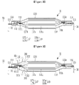
FIG. 2 , abattery cell 11 may include an electrode assembly in which apositive electrode layer 117, anisolation layer 118, and anegative electrode layer 119 are repeatedly stacked in the order of thepositive electrode layer 117, theisolation layer 118, and thenegative electrode layer 119 and acase 110. Thepositive electrode layer 117 includes apositive electrode 117a and apositive electrode tab 117b, and thepositive electrode tab 117b is extended from thepositive electrode 117a and protrudes to one side of thecase 110 to be connected with apositive electrode lead 117c. Thenegative electrode layer 119 includes anegative electrode 119a and anegative electrode tab 119b, and thenegative electrode tab 119b is extended from thenegative electrode 119a and protrudes to the other side of thecase 110 to be connected with anegative electrode lead 119c. Thecase 110 accommodates the electrode assembly. - In
FIGS. 1 and2 , the positive electrode tab and the negative electrode tab protrude in opposite directions, but the present invention is not limited thereto. The present invention is applicable even to a battery system including a battery cell in which a positive electrode tab and a negative electrode tab protrude in the same direction. - The
positive lead 117c is electrically connected to alead electrode 113, thelead electrode 113 and alead electrode 111 are electrically connected through aconductive polymer 112, and thelead electrode 111 is electrically connected to abus bar 32. - In particular, a part of a lower end surface of the lead electrode 113 (a part of a left lower end surface in
FIG. 2 ) is in contact with thepositive electrode tab 117b, another part of the lower end surface of the lead electrode 113 (a part of a right lower end surface inFIG. 2 ) and a part of an upper end surface of the lead electrode 111 (a part of a left upper end surface inFIG. 2 ) overlap each other, and theconductive polymer 112 is located therebetween. - The
negative electrode lead 119c is electrically connected to alead electrode 115, and thelead electrode 115 is connected to abus bar 36. - A
film 114 surrounds a region including a portion in which thelead electrode 111, thelead electrode 113, and theconductive polymer 112 overlap. Afilm 116 surrounds a partial region of thelead electrode 115. - The
case 110 accommodates the electrode assembly, thelead electrode 111 protrudes to the outside through an opening at one side of thecase 110 to be connected to thebus bar 32, and thelead electrode 115 is connected to thebus bar 36 through an opening at the other side of thecase 110. The opening at one side is sealed by thefilm 114, or by thefilm 114 and a sealant, and the opening at the other side may be sealed by thefilm 116, or by thefilm 116 and a sealant. - The plurality of
battery cells 12 to 18 may be implemented in the same structure as that of thebattery cell 11. - Referring back to
FIG. 1 , thebattery system 1 will be described. - The
lead electrode 111 that is the positive electrode of thebattery cell 11 and thelead electrode 121 that is the positive electrode of thebattery cell 12 are connected to thebus bar 32, and thebus bar 32 is connected to apositive electrode 31 of thebattery system 1. Thelead electrodes battery cells lead electrodes battery cells bus bar 36,lead electrodes battery cells lead electrodes battery cells bus bar 33,lead electrodes battery cells lead electrodes battery cells bus bar 35, andlead electrodes battery cells bus bar 34. Thebus bar 34 is connected to anegative electrode 37 of thebattery system 1. - The
BMS 20 may supply a diagnosis voltage between two bus bars among the plurality ofbus bars 32 to 36, and measure resistance of the battery bank. As mentioned above, inFIG. 1 , two adjacent battery cells are connected to each other in parallel to configure one battery bank. However, the invention is not limited thereto, the battery cells are serially connected like the method illustrated inFIG. 1 in the unit of one battery cell, instead of the battery bank, or the battery bank may include at least three battery cells. - The
BMS 20 measures resistance of the plurality of battery banks including two battery cells among the plurality ofbattery cells 11 to 18, and when the resistance of the battery bank is equal to or larger than a predetermined value, theBMS 20 diagnoses that the corresponding battery bank has abnormality. - For example, it is described that the
BMS 20 measures the resistance of the battery bank consisting of twobattery cells battery cells 11 to 18. -
FIG. 3 is a diagram illustrating the case where abnormality occurs in one of a plurality of battery cells. - In
FIG. 3 , gas is generated in thebattery cell 11 and thecase 110 is expanded from indicateddotted lines solid lines - The
BMS 20 supplies a diagnosis voltage between thebus bar 32 and thebus bar 36 through awire 41 and awire 45. In this case, the diagnosis current flowing through thebattery cells wire 41 and thewire 45, and theBMS 20 may measure a diagnosis voltage and the diagnosis current to calculate the resistance of the battery bank. - As illustrated in
FIG. 3 , when an abnormality occurs in thebattery cell 11 among thebattery cells lead electrode 113 and thelead electrode 111 is increased due to an increase in pressure inside thebattery cell 11. This is due to the force acting in the two arrow directions of the drawing by the internal pressure of thebattery cell 11. Then, theconductive polymer 112 is expanded by force acted in both vertical directions. As the gap between the twolead electrodes BMS 20 increases. - By the same method, the
BMS 20 may supply the diagnosis voltage between thebus bar 36 and thebus bar 33 through thewire 45 and thewire 42 in order to diagnose abnormalities of thebattery cells wire 41 and thewire 45 and calculate the resistance of the battery bank. TheBMS 20 may supply the diagnosis voltage between thebus bar 33 and thebus bar 36 through thewire 42 and thewire 44 in order to diagnose abnormalities of thebattery cells wire 42 and thewire 44 and calculate the resistance of the battery bank. TheBMS 20 may supply the diagnosis voltage between thebus bar 35 and thebus bar 34 through thewire 44 and thewire 43 in order to diagnose abnormalities of thebattery cells wire 44 and thewire 43 and calculate the resistance of the battery bank. - The
BMS 20 divides the measured diagnosis current by the supplied diagnosis voltage and calculates the resistance of the corresponding battery bank. In this case, when a resistance increase speed of the battery bank is low, but reaches a threshold value, theBMS 20 may generate an inspection signal. When the increase speed is equal to or lower than a predetermined first reference value, it may be determined that the resistance increase speed is low, and the predetermined reference value may be set according to a design. Further, when the resistance of the battery bank reaches the threshold value at a rapid increase speed, theBMS 20 may generate a warning signal. When the increase speed is larger than the first reference value, theBMS 20 may determine that the resistance increase speed is high. Further, when the resistance of the battery bank reaches the threshold value at a very rapid increase speed, there is a risk of ignition, so that theBMS 20 may generate an evacuation warning signal. When the increase speed is larger than a predetermined second reference value that is larger than the first reference value, theBMS 20 may determine that the resistance increase speed is very high. - The
BMS 20 may stop the operation of thebattery system 1 according to the inspection signal, the warning signal, and the evacuation warning signal, and transmit the stop of the operation of thebattery system 1 to a circuit controlling the vehicle through the CAN communication, and notify a user of an abnormality of thebattery system 1 through a separate device. The inspection signal is a signal to inform the user that the battery system needs to be inspected, the warning signal is a signal to inform the user that the battery system is in a dangerous state and needs replacement, and the evacuation warning signal is a signal to warn the user to evacuate immediately. The response matter according to each signal may be appropriately designed according to the design. -
FIGS. 1 to 3 illustrate that the lead electrode, the conductive polymer, and the lead electrode are located at both sides of the battery cell, but the invention is not limited thereto. -
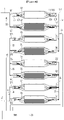
FIG. 4 is a diagram illustrating a battery system according to an exemplary embodiment. - As illustrated in
FIG. 4 , alead electrode 513 is electrically connected to anegative electrode lead 516, aconductive polymer 512 is located between thelead electrode 513 and thelead electrode 515, and thelead electrode 515 is connected to abus bar 36. Afilm 518 surrounds a region including a portion in which thelead electrode 513, theconductive polymer 512, and thelead electrode 515 overlap. Thelead electrode 511 is connected to apositive electrode lead 514 and abus bar 32. Thefilm 517 surrounds a partial region of thelead electrode 511. - A
lead electrode 511 that is a positive electrode of abattery cell 51 and alead electrode 521 that is a positive electrode of abattery cell 52 are connected to thebus bar 32, and thebus bar 32 is connected to thepositive electrode 31 of thebattery system 1. Leadelectrodes battery cells lead electrodes battery cells bus bar 36,lead electrodes 535 and 545 that are the negative electrodes of thebattery cells lead electrodes battery cells bus bar 33,lead electrodes battery cells lead electrodes battery cells bus bar 35, and leadelectrodes battery cells bus bar 34. The bus bar 34 s connected to anegative electrode 37 of thebattery system 1. - Identically to the exemplary embodiment of
FIG. 1 , theBMS 20 of the exemplary embodiment ofFIG. 4 may supply a diagnosis voltage between two bus bars among the plurality ofbus bars 32 to 36, and measure resistance of the battery bank. A detailed description thereof will be omitted. -
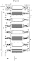
FIG. 5 is a diagram illustrating a battery system according to an exemplary embodiment. - As illustrated in
FIG. 5 , alead electrode 613 is electrically connected to apositive electrode lead 617, aconductive polymer 612 is located between thelead electrode 613 and thelead electrode 611, and thelead electrode 611 is connected to abus bar 32. Alead electrode 616 is electrically connected to anegative electrode lead 618, aconductive polymer 614 is located between thelead electrode 616 and thelead electrode 615, and thelead electrode 615 is connected to abus bar 36. Afilm 619a surrounds a region including a portion in which thelead electrode 613, theconductive polymer 612, and thelead electrode 611 overlap, and afilm 619b surrounds a region including a portion in which thelead electrode 616, theconductive polymer 614, and thelead electrode 615 overlap. - A
lead electrode 611 that is a positive electrode of abattery cell 61 and alead electrode 621 that is a positive electrode of abattery cell 62 are connected to thebus bar 32, and thebus bar 32 is connected to apositive electrode 31 of thebattery system 1. Leadelectrodes battery cells lead electrodes battery cells bus bar 36,lead electrodes battery cells lead electrodes battery cells bus bar 33,lead electrodes battery cells lead electrodes battery cells bus bar 35, and leadelectrodes battery cells bus bar 34. The bus bar 34 s connected to anegative electrode 37 of thebattery system 1. - Identically to the exemplary embodiment of
FIG. 1 , theBMS 20 of the exemplary embodiment ofFIG. 5 may supply a diagnosis voltage between two bus bars among the plurality ofbus bars 32 to 36, and measure resistance of the battery bank. A detailed description thereof will be omitted. - In the foregoing exemplary embodiment, the
BMS 20 detects abnormality based on an increase speed of resistance, but the invention is not limited thereto, and the present invention may detect that there is abnormality in a battery cell or a battery bank having a resistance value equal to or larger than a predetermined threshold value compared to other battery cells or battery bank. - The battery system according to the exemplary embodiment is applicable to an Energy Storage System (ESS), as well as a vehicle, and when the signal generated from the
BMS 20 interlocks with the firefighting equipment, a fire suppression operation may be performed when ignition occurs due to abnormality of the ESS. For example, a fire alarm device may be operated and a fire door may be activated. - While this invention has been described in connection with what is presently considered to be practical exemplary embodiments, it is to be understood that the invention is not limited to the disclosed embodiments.
Claims (10)
- A battery cell, comprising:an electrode assembly;a case configured to accommodate the electrode assembly;a first lead electrode electrically connected to at least one of two electrode tabs of the electrode assembly;a conductive polymer including a first surface that is in contact with a first surface of the first lead electrode; anda second lead electrode including a first surface that is in contact with a second surface of the conductive polymer,wherein the first lead electrode and the second lead electrode are positioned such that an increase a gap between the first lead electrode and the second lead electrodecorresponds to an increase in resistance between the first lead electrode and the second lead electrode.
- The battery cell of claim 1, further comprising:
a film configured to surround a region including a portion in which the first lead electrode, the conductive polymer, and the second lead electrode overlap. - The battery cell of claim 1, wherein:
the second lead electrode protrudes to an exterior of the case and is connected to a bus bar. - A battery system, comprising:a plurality of battery cells; anda battery management system,wherein each of the a plurality of battery cells includes:an electrode assembly;a case configured to accommodate the electrode assembly;a first lead electrode electrically connected to at least one of two electrode tabs of the electrode assembly;a conductive polymer including a first surface that is in contact with a first surface of the first lead electrode; anda second lead electrode including a first surface that is in contact with a second surface of the conductive polymer,wherein the battery management system is configured to:detect an increase in resistance of at least one of the plurality of battery cells; anddiagnose an abnormality based on the detected increase in resistance.
- The battery management system of claim 4, wherein:
the battery management system is configured to generate an inspection signal in response to a resistance increase speed of at least one of the plurality of battery cells reaching a predetermined threshold value that is equal to or smaller than a first reference value. - The battery management system of claim 5, wherein:
the battery management system is configured to generate a warning signal in response to the resistance increase speed of at least one of the plurality of battery cells reaching the predetermined threshold value at a higher speed than the first reference value. - The battery management system of claim 5, wherein:
the battery management system is configured to generate an evacuation warning signal in response to the resistance increase speed of at least one of the plurality of battery cells reaching the predetermined threshold value by a second reference value or more that is larger than the first reference value. - The battery management system of claim 4, wherein:each of the plurality of battery cells further includes a film configured to surround a region including a portion in which the first lead electrode, the conductive polymer, and the second lead electrode overlap.
- The battery management system of claim 4, wherein:
the second lead electrode protrudes to an exterior of the case and is connected to a bus bar. - The battery management system of claim 4, wherein:
the battery management system is configured to:supply a diagnosis voltage to both ends of at least one of the plurality of battery cells;measure a diagnosis current flowing in said at least one of the plurality of battery cells; andcalculate a resistance of said at least one of the plurality of battery cells.
Applications Claiming Priority (2)
| Application Number | Priority Date | Filing Date | Title |
|---|---|---|---|
| KR1020200056952A KR20210138913A (en) | 2020-05-13 | 2020-05-13 | Battery cell and battery system comprising the same |
| PCT/KR2021/004999 WO2021230516A1 (en) | 2020-05-13 | 2021-04-21 | Battery cell and battery system comprising same |
Publications (1)
| Publication Number | Publication Date |
|---|---|
| EP4068467A1 true EP4068467A1 (en) | 2022-10-05 |
Family
ID=78525207
Family Applications (1)
| Application Number | Title | Priority Date | Filing Date |
|---|---|---|---|
| EP21804477.4A Pending EP4068467A1 (en) | 2020-05-13 | 2021-04-21 | Battery cell and battery system comprising same |
Country Status (6)
| Country | Link |
|---|---|
| US (1) | US20220416314A1 (en) |
| EP (1) | EP4068467A1 (en) |
| JP (1) | JP7381029B2 (en) |
| KR (1) | KR20210138913A (en) |
| CN (1) | CN114930611A (en) |
| WO (1) | WO2021230516A1 (en) |
Family Cites Families (7)
| Publication number | Priority date | Publication date | Assignee | Title |
|---|---|---|---|---|
| US8669003B2 (en) * | 2006-04-03 | 2014-03-11 | Lg Chem, Ltd. | Lithium secondary battery improved safety and capacity |
| US20090162738A1 (en) * | 2007-12-25 | 2009-06-25 | Luxia Jiang | Battery system with heated terminals |
| US8361646B2 (en) * | 2010-03-15 | 2013-01-29 | Electronvault, Inc. | Modular interconnection system |
| WO2018200487A1 (en) * | 2017-04-27 | 2018-11-01 | University Of Houston System | Stretchable fabric based electrode-polymer electrolyte battery |
| KR102268402B1 (en) * | 2017-08-29 | 2021-06-24 | 주식회사 엘지에너지솔루션 | The Pouch Type Secondary Battery |
| KR102288121B1 (en) * | 2017-09-07 | 2021-08-11 | 주식회사 엘지에너지솔루션 | The Pouch Type Secondary Battery |
| US10549640B2 (en) | 2017-11-09 | 2020-02-04 | Ford Global Technologies, Llc | Mechanically amplified battery cell pressure sensor |
-
2020
- 2020-05-13 KR KR1020200056952A patent/KR20210138913A/en active Search and Examination
-
2021
- 2021-04-21 EP EP21804477.4A patent/EP4068467A1/en active Pending
- 2021-04-21 WO PCT/KR2021/004999 patent/WO2021230516A1/en unknown
- 2021-04-21 CN CN202180008406.2A patent/CN114930611A/en active Pending
- 2021-04-21 JP JP2022518347A patent/JP7381029B2/en active Active
- 2021-04-21 US US17/787,618 patent/US20220416314A1/en active Pending
Also Published As
| Publication number | Publication date |
|---|---|
| CN114930611A (en) | 2022-08-19 |
| WO2021230516A1 (en) | 2021-11-18 |
| JP2022550027A (en) | 2022-11-30 |
| JP7381029B2 (en) | 2023-11-15 |
| US20220416314A1 (en) | 2022-12-29 |
| KR20210138913A (en) | 2021-11-22 |
Similar Documents
| Publication | Publication Date | Title |
|---|---|---|
| EP2171824B1 (en) | Method of deactivating faulty battery cells | |
| JP2015521347A (en) | Cover film for galvanic element, electrochemical power storage device, electrochemical power storage system, flexible film for galvanic element cover, and method for calculating state parameters of electrochemical power storage device | |
| EP3840083B1 (en) | Thermal runaway detection system and battery system | |
| EP3904142A1 (en) | Vehicle battery fire detection device and detection method | |
| KR20130137389A (en) | Apparatus and method for checking current sensor abnormality in battery pack | |
| US20210194072A1 (en) | Thermal runaway detection system and battery system | |
| JP2011119157A (en) | Battery power source device and battery power source system | |
| US20220126698A1 (en) | Vehicle battery fire sensing apparatus and method | |
| KR20160113888A (en) | Battery pack | |
| US11316210B2 (en) | Control unit for a battery module or system | |
| US11799138B2 (en) | Apparatus for detecting thermal runaway of battery for electric vehicle | |
| US20220093984A1 (en) | Battery protection apparatus and battery system including the same | |
| US20130252051A1 (en) | Battery system | |
| JP5092268B2 (en) | Leak detection device for power system | |
| CN106458038B (en) | It runs the method for Storage Unit, implement the battery management system of this method | |
| KR20220049142A (en) | Apparatus of detecting thermal runaway for electric vehicle | |
| EP4068467A1 (en) | Battery cell and battery system comprising same | |
| JP2014048281A (en) | Electric power unit and failure detection circuit | |
| JP2005322471A (en) | Detection device for detecting defect state of battery safety valve, and battery and assembled battery having detection device | |
| TWI565172B (en) | Battery monitoring system and method thereof | |
| JP7381987B2 (en) | Battery pack abnormality detection device | |
| KR20220028991A (en) | Apparatus of detecting thermal runaway for electric vehicle | |
| CN114690042A (en) | Power battery safety monitoring device and vehicle | |
| US20140335384A1 (en) | Battery, motor vehicle and method for operating the battery | |
| EP3657592B1 (en) | Control unit for a battery module or system |
Legal Events
| Date | Code | Title | Description |
|---|---|---|---|
| STAA | Information on the status of an ep patent application or granted ep patent |
Free format text: STATUS: THE INTERNATIONAL PUBLICATION HAS BEEN MADE |
|
| PUAI | Public reference made under article 153(3) epc to a published international application that has entered the european phase |
Free format text: ORIGINAL CODE: 0009012 |
|
| STAA | Information on the status of an ep patent application or granted ep patent |
Free format text: STATUS: REQUEST FOR EXAMINATION WAS MADE |
|
| 17P | Request for examination filed |
Effective date: 20220701 |
|
| AK | Designated contracting states |
Kind code of ref document: A1 Designated state(s): AL AT BE BG CH CY CZ DE DK EE ES FI FR GB GR HR HU IE IS IT LI LT LU LV MC MK MT NL NO PL PT RO RS SE SI SK SM TR |
|
| DAV | Request for validation of the european patent (deleted) | ||
| DAX | Request for extension of the european patent (deleted) |