EP4068462A1 - Fuel cell jig comprising film-type pressure sensor and method of measuring swelling of fuel cell by using same - Google Patents
Fuel cell jig comprising film-type pressure sensor and method of measuring swelling of fuel cell by using same Download PDFInfo
- Publication number
- EP4068462A1 EP4068462A1 EP21851235.8A EP21851235A EP4068462A1 EP 4068462 A1 EP4068462 A1 EP 4068462A1 EP 21851235 A EP21851235 A EP 21851235A EP 4068462 A1 EP4068462 A1 EP 4068462A1
- Authority
- EP
- European Patent Office
- Prior art keywords
- battery cell
- film
- jig
- type pressure
- pressure sensors
- Prior art date
- Legal status (The legal status is an assumption and is not a legal conclusion. Google has not performed a legal analysis and makes no representation as to the accuracy of the status listed.)
- Pending
Links
- 230000008961 swelling Effects 0.000 title claims abstract description 24
- 238000000034 method Methods 0.000 title claims abstract description 16
- 239000000446 fuel Substances 0.000 title 2
- 238000003825 pressing Methods 0.000 claims description 12
- 239000000758 substrate Substances 0.000 claims description 12
- 238000003860 storage Methods 0.000 claims description 6
- 238000007599 discharging Methods 0.000 claims 1
- 230000002159 abnormal effect Effects 0.000 abstract description 9
- 230000007850 degeneration Effects 0.000 abstract description 8
- 238000005516 engineering process Methods 0.000 abstract description 3
- 239000000463 material Substances 0.000 description 4
- HBBGRARXTFLTSG-UHFFFAOYSA-N Lithium ion Chemical compound [Li+] HBBGRARXTFLTSG-UHFFFAOYSA-N 0.000 description 2
- 230000008901 benefit Effects 0.000 description 2
- 238000011156 evaluation Methods 0.000 description 2
- 239000010408 film Substances 0.000 description 2
- 230000001965 increasing effect Effects 0.000 description 2
- 230000001939 inductive effect Effects 0.000 description 2
- 229910001416 lithium ion Inorganic materials 0.000 description 2
- 238000011160 research Methods 0.000 description 2
- WHXSMMKQMYFTQS-UHFFFAOYSA-N Lithium Chemical compound [Li] WHXSMMKQMYFTQS-UHFFFAOYSA-N 0.000 description 1
- XAGFODPZIPBFFR-UHFFFAOYSA-N aluminium Chemical compound [Al] XAGFODPZIPBFFR-UHFFFAOYSA-N 0.000 description 1
- 229910052782 aluminium Inorganic materials 0.000 description 1
- 238000009530 blood pressure measurement Methods 0.000 description 1
- 230000006835 compression Effects 0.000 description 1
- 238000007906 compression Methods 0.000 description 1
- 238000000354 decomposition reaction Methods 0.000 description 1
- 230000006866 deterioration Effects 0.000 description 1
- 238000011161 development Methods 0.000 description 1
- 238000010586 diagram Methods 0.000 description 1
- 230000000694 effects Effects 0.000 description 1
- 238000003912 environmental pollution Methods 0.000 description 1
- 239000002803 fossil fuel Substances 0.000 description 1
- 238000010438 heat treatment Methods 0.000 description 1
- 229910052744 lithium Inorganic materials 0.000 description 1
- 230000007774 longterm Effects 0.000 description 1
- 238000004519 manufacturing process Methods 0.000 description 1
- 238000005259 measurement Methods 0.000 description 1
- 238000012986 modification Methods 0.000 description 1
- 230000004048 modification Effects 0.000 description 1
- 238000013021 overheating Methods 0.000 description 1
- 229920000642 polymer Polymers 0.000 description 1
- 238000010248 power generation Methods 0.000 description 1
- 230000003252 repetitive effect Effects 0.000 description 1
- 238000000926 separation method Methods 0.000 description 1
- 239000010409 thin film Substances 0.000 description 1
Images


Classifications
-
- H—ELECTRICITY
- H01—ELECTRIC ELEMENTS
- H01M—PROCESSES OR MEANS, e.g. BATTERIES, FOR THE DIRECT CONVERSION OF CHEMICAL ENERGY INTO ELECTRICAL ENERGY
- H01M10/00—Secondary cells; Manufacture thereof
- H01M10/42—Methods or arrangements for servicing or maintenance of secondary cells or secondary half-cells
- H01M10/4285—Testing apparatus
-
- G—PHYSICS
- G01—MEASURING; TESTING
- G01B—MEASURING LENGTH, THICKNESS OR SIMILAR LINEAR DIMENSIONS; MEASURING ANGLES; MEASURING AREAS; MEASURING IRREGULARITIES OF SURFACES OR CONTOURS
- G01B5/00—Measuring arrangements characterised by the use of mechanical techniques
- G01B5/30—Measuring arrangements characterised by the use of mechanical techniques for measuring the deformation in a solid, e.g. mechanical strain gauge
-
- G—PHYSICS
- G01—MEASURING; TESTING
- G01R—MEASURING ELECTRIC VARIABLES; MEASURING MAGNETIC VARIABLES
- G01R31/00—Arrangements for testing electric properties; Arrangements for locating electric faults; Arrangements for electrical testing characterised by what is being tested not provided for elsewhere
- G01R31/36—Arrangements for testing, measuring or monitoring the electrical condition of accumulators or electric batteries, e.g. capacity or state of charge [SoC]
- G01R31/385—Arrangements for measuring battery or accumulator variables
- G01R31/3865—Arrangements for measuring battery or accumulator variables related to manufacture, e.g. testing after manufacture
-
- H—ELECTRICITY
- H01—ELECTRIC ELEMENTS
- H01M—PROCESSES OR MEANS, e.g. BATTERIES, FOR THE DIRECT CONVERSION OF CHEMICAL ENERGY INTO ELECTRICAL ENERGY
- H01M10/00—Secondary cells; Manufacture thereof
- H01M10/04—Construction or manufacture in general
- H01M10/0481—Compression means other than compression means for stacks of electrodes and separators
-
- H—ELECTRICITY
- H01—ELECTRIC ELEMENTS
- H01M—PROCESSES OR MEANS, e.g. BATTERIES, FOR THE DIRECT CONVERSION OF CHEMICAL ENERGY INTO ELECTRICAL ENERGY
- H01M10/00—Secondary cells; Manufacture thereof
- H01M10/42—Methods or arrangements for servicing or maintenance of secondary cells or secondary half-cells
- H01M10/48—Accumulators combined with arrangements for measuring, testing or indicating the condition of cells, e.g. the level or density of the electrolyte
-
- Y—GENERAL TAGGING OF NEW TECHNOLOGICAL DEVELOPMENTS; GENERAL TAGGING OF CROSS-SECTIONAL TECHNOLOGIES SPANNING OVER SEVERAL SECTIONS OF THE IPC; TECHNICAL SUBJECTS COVERED BY FORMER USPC CROSS-REFERENCE ART COLLECTIONS [XRACs] AND DIGESTS
- Y02—TECHNOLOGIES OR APPLICATIONS FOR MITIGATION OR ADAPTATION AGAINST CLIMATE CHANGE
- Y02E—REDUCTION OF GREENHOUSE GAS [GHG] EMISSIONS, RELATED TO ENERGY GENERATION, TRANSMISSION OR DISTRIBUTION
- Y02E60/00—Enabling technologies; Technologies with a potential or indirect contribution to GHG emissions mitigation
- Y02E60/10—Energy storage using batteries
Definitions
- the present invention relates to a battery cell jig including a film-type pressure sensor, and a method for measuring a swelling of a battery cell.
- lithium secondary batteries such as lithium ion batteries and lithium ion polymer batteries having advantages such as high energy density, discharge voltage, and output stability.
- Such a secondary battery is formed in a structure such that an electrode assembly including a positive electrode, a negative electrode, and a separator disposed therebetween is built in a battery case, and positive and negative electrode tabs are welded to two electrode leads and are sealed to be exposed to the outside of the battery case.
- the electrode tab is electrically connected to the external device through contact with the external device, and the secondary battery supplies power to the external device through the electrode tab or receives power from the external device.
- gas may be generated inside the secondary battery.
- overheated battery may generate gas and promote the decomposition reaction of battery elements, thereby causing continuous heating, gas generation, and a swelling phenomenon. This phenomenon also appears in the slow deterioration process of secondary batteries due to long-term use.
- an aspect of the present invention provides a battery cell jig including a film-type pressure sensor, and a method for measuring a swelling of a battery cell using the same.
- a battery cell jig including a film-type pressure sensor.
- a battery cell jig according to the present invention includes: first and second plates which have a battery cell therebetween and press two surfaces of the battery cell; bolts and nuts which fix the first and second plates to press the battery cell; a charge and discharge unit which is electrically connected to the battery cell; and a sensor unit which is positioned between the battery cell and the first plate and measures a pressure that is changed when the battery cell is charged or discharged.
- the sensor unit has a structure where n film-type pressure sensors are arranged on a substrate (the n is an integer equal to or greater than 2).
- the battery cell jig according to the present invention further includes: an output unit which is connected to the sensor unit and outputs a pressure value of the battery cell; and a storage unit which stores an output value which is output from the output unit.
- the n film-type pressure sensors may be connected to each other by a flexible print circuit (FPC) pattern, and pressure values measured in the n film-type pressure sensors may be collected as one output value and the output value is then output.
- the n film-type pressure sensors may be arranged on a front surface of the substrate and may be uniformly arranged along a first direction and a second direction.
- each of the film-type pressure sensors may be a pressure sensitive resistor (PSR) sensor.
- PSR pressure sensitive resistor
- the sensor unit of the battery cell jig according to the present invention may be arranged on one side surface of the battery cell and may further include a pressing plate at a space between the sensor unit and the first plate. At this time, a coil spring may be arranged between the pressing plate and the first plate.
- a plurality of battery cells may be laminated and accommodated between the first and second plates, and the plurality of battery cells may be electrically connected to each other in series or in parallel.
- the present invention provides a method for measuring a swelling of a battery cell using the above-described battery cell jig.
- the method for measuring a swelling of a battery cell according to the present invention includes measuring a swelling of a battery cell by inducing a swelling of the battery cell according to charge and discharge by arranging the battery cell on the battery cell jig according to claim 1, and sensing a pressure change of the battery cell using the film-type pressure sensors of the sensor unit.
- the measuring of the swelling of the battery cell may include collecting pressure values measured in n film-type pressure sensors as one output value and outputting the output value.
- the pressure change of the battery cell can be easily measured using n film-type pressure sensors (n is an integer equal to or greater than 2).
- the battery cell jig of the present invention can reduce the volume of the measuring apparatus and can prevent the abnormal degeneration of the battery cell by the difference in pressure for each location of the battery cell.
- the present invention relates to a battery cell jig including a film-type pressure sensor, and a method for measuring a swelling of a battery cell.
- the pressure measurement jig for measuring the pressure change of the conventional battery cell has a large weight and volume, and accordingly, there is a spatial limitation in the battery evaluation. Further, when evaluating a battery, if the existing pressure sensor is used, the difference in pressure occurs for each location of the battery cell by the thickness of the pressure sensor itself, thereby causing abnormal degeneration of the battery cell.
- the inventors of the present invention invented a battery cell jig for reducing the volume of a measuring apparatus and preventing abnormal degeneration of a battery cell due to the pressure difference for each location of the battery cell, and a method of measuring a swelling of a battery cell using the same.
- the battery cell jig of the present invention can reduce the volume of the measuring apparatus and can prevent the abnormal degeneration of the battery cell by the difference in pressure for each location of the battery cell.
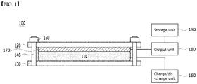
- FIG. 1 is a schematic view of a battery cell jig according to the present invention
- FIG. 3 is a schematic view showing a sensor unit of a battery cell jig according to the present invention.
- a battery cell jig 100 includes: first and second plates 120 and 130 which have a battery cell therebetween and press two surfaces of the battery cell; bolts 140 and nuts 150 which fix the first and second plates 120 and 130 to press the battery cell 110; a charge and discharge unit 160 which is electrically connected to the battery cell 110; and a sensor unit 170 which is positioned between the battery cell 110 and the first plate 120 and measures a pressure that is changed when the battery cell 110 is charged or discharged.
- the sensor unit 170 may have a structure where n film-type pressure sensors are arranged on a substrate.
- the n is an integer equal to or greater than 2.
- the battery cell 110 which is interposed between the first and second plates 120 and 130, may be a pouch-type unit cell.
- the pouch type unit cell may have a structure that an electrode assembly having a positive electrode/ separator/ negative electrode structure is embedded in an exterior material of the laminate sheet in a state that is connected to electrode leads formed outside the exterior material. Further, the electrode leads may be drawn to the outside of the sheet and may be extended in the same or opposite direction to each other.
- first and second plates 120 and 130 may be general plates which are used when evaluating charge/discharge characteristics of the battery cell 110, for example, aluminum plates.
- the battery cell jig 100 measures the pressure change of the battery cell 110 using film-type pressure sensors 172 during the charge/discharge of the battery cell 110.
- the film-type pressure sensor 172 is a pressure sensitive resistor (PSR) sensor and can sense pressure or force, and is a sensor for measuring the changed value of resistance according to the change of pressure or force applied to the surface of the PSR sensor.
- the PSR sensor is a thin film type and can reduce the volume of an apparatus for measuring the pressure of the battery cell 110 and can prevent abnormal degeneration of the battery cell 110 by the pressure difference for each location of the battery cell 110.
- the sensor unit 170 of the battery cell jig 100 includes a substrate and film-type pressure sensors 172.
- the substrate may be made of an insulating flexible material and may have a size corresponding to the area of one surface of the battery cell 110.
- the film-type pressure sensor 172 may be disposed on the front surface of the substrate 171.
- the film-type pressure sensors 172 are arranged on the front surface of the substrate 171 and are uniformly arranged along the first direction and the second direction.
- the first direction may refer to the row direction
- the second direction may refer to the column direction.
- n film-type pressure sensors 172 may be uniformly arranged along the first direction and the second direction of the substrate 171 so that the sensor unit 170 can evenly sense the entire area of the battery cell 110. It is illustrated that there are 18 film-type pressure sensors 172, but the number of the film-type pressure sensors 172 may be selectable in the range of 2 to 100 or 5 to 50.
- the n film-type pressure sensors may be connected to each other in a flexible print circuit (FPC) pattern.
- the sensor unit 170 may have a structure that n film-type pressure sensors 172 are arranged on an insulating, flexible substrate, and the film-type pressure sensors 172 are connected by an electronic circuit.
- pressure values, which are measured in the n film-type pressure sensors 172 connected in the FPC pattern are collected as one output value, and the output value is output.
- the pressure values, which are measured in the n film-type pressure sensors 172 are not individually output, and the sum of the pressure values measured in the n film-type pressure sensors 172 is output.
- the output value may be s + 2s + 3s + ... + ns.
- the conventional FSR pressure sensor had a limitation in being used as a sensor for measuring the pressure of the battery cell 110 because maximum measurable pressure range was narrow.
- the pressure values, which are measured in a plurality of film-type pressure sensors 172 can be collected as one output value, the measurable pressure range can be widened.
- the battery cell jig 100 for measuring a swelling of a battery cell may further include a charge/discharge unit 160 which is electrically connected to the battery cell 110.
- the charge/discharge unit 160 may supply power for charge to the battery cell 110 or receive discharge power from the battery cell 110.
- supplying power to the battery cell 110 is not limited to supplying power which is sufficient for fully charging the battery cell 110. The same may be applied to the meaning of receiving discharge power from the battery cell 110, and thus repeated description thereof is omitted here.
- the battery cell jig 100 further includes an output unit 180 which is connected to the sensor unit 170 and outputs the pressure value of the battery cell 110 and a storage unit 190 which stores the output value which is output from the output unit 180.
- the output unit 180 may numerically calculate and display the change in pressure which is applied from the battery cell 110 based on the signal inputted from the n film-type pressure sensors 172, and may output the change in pressure, which is applied from the battery cell 110, in real time.
- the storage unit 190 may receive the output value from the output unit 180 and store the output value and may store information on the swelling result of the battery cell 110 and build a database based on the information. For example, information on the pressure value for the driving condition of the charge/discharge unit may be made and stored as a table or a graph. Such measurement data can be used as the basis for predicting the swelling degree or input value of the battery cell 110 when various charge/discharge conditions of the charge/discharge unit 160 are combined.
- FIG. 3 is a schematic view of a battery cell jig according to another embodiment of the present invention.
- the battery cell jig 200 according to the present invention further includes a pressing plate 225.
- the sensor unit 270 has a structure that is arranged on one side surface of the battery cell 210, and the battery cell jig 200 according to the present invention may further include the pressing plate 225 between the sensor unit 270 and the first plate 220.
- the pressing plate 225 is a plate for applying constant pressure to the battery cell 210 and may have a structure which is fastened by bolts 240 and nuts 250 between first and second plates 220 and 230 as in the first and second plates 220 and 230. Further, in order to the pressing plate 225 to apply constant pressure to the battery cell 210, at least one coil spring 226 may be arranged between the pressing plate 225 and the first plate 220.
- the coil spring 226 may be a compression spring as a spring with a force resistant to the compressive force and is configured to apply constant pressure to the pressing plate 225.
- the battery cell 210 is accommodated in the battery cell jig 200, and the battery cell 210 is repeatedly charged and discharged, the battery cell is swollen. At this time, as the battery cell 210 is swollen, the pressing plate 225 is pushed up, and at the same time, the sensor unit 270 measures the pressure which is the swollen value of the battery cell.
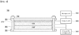
- FIG. 4 is a schematic view of a battery cell jig according to further another embodiment of the present invention.
- the battery cell jig 300 has a structure where a plurality of battery cells 310 and 310' are laminated.
- a plurality of battery cells 310 and 310' are laminated and accommodated between the first and second plates 320 and 330, and the plurality of battery cells 310 and 310' may be electrically connected to each other in series or in parallel.
- the present invention is not limited thereto, and in some cases, it is possible to independently apply power source to each of the battery cells 310 and 310'.
- the plurality of battery cells 310 and 310' show a structure where 2 battery cells are laminated, and the number of battery cells may be selected, for example, in the range of 2 to 10.
- the increased status of the pressure can be recognized and analyzed by comparing with the result of measuring only one battery cell 310.
- 2 battery cells 310 and 310' are laminated and the pressure change is measured, and it is possible to recognize whether the pressure has doubled or the pressure increase was suppressed/amplified, compared to the case of measuring only one battery cell 310.
- the present invention provides a method for measuring a swelling of a battery cell using the above-described battery cell jig.
- the method for measuring a swelling of a battery cell according to the present invention includes measuring a swelling of a battery cell by inducing a swelling of the battery cell according to charge and discharge by arranging the battery cell on the battery cell jig according to claim 1, and sensing a pressure change of the battery cell using the film-type pressure sensors of the sensor unit.
- the battery cell to be measured is arranged between first and second plates, and a sensor unit is seated on one surface of the battery cell. Further, the separation distance of the first and second plates is fixed by using bolts and nuts. Thereafter, charge/discharge is repeatedly performed by applying a voltage to the battery cell using the charge/discharge unit.
- the sensor unit can measure the pressure change according thereto.
- the measuring of the swelling of the battery cell may include collecting pressure values measured in n film-type pressure sensors as one output value and outputting the output value.
- n film-type pressure sensors are connected to each other in a FPC pattern, and pressure values, which are measured by the n film-type pressure sensors, can be collected as one output value to thereby be outputted. Namely, the pressure values, which are measured in the n film-type pressure sensors, are not individually output, and the sum of the pressure values measured in the n film-type pressure sensors is output.
- the battery cell jig of the present invention can reduce the volume of the measuring apparatus and can prevent the abnormal degeneration of the battery cell by the difference in pressure for each location of the battery cell.
Abstract
Description
- This application claims the benefit of priority based on
Korean Patent Application No. 10-2020-0095681, filed on July 31, 2020 - The present invention relates to a battery cell jig including a film-type pressure sensor, and a method for measuring a swelling of a battery cell.
- In recent years, as the price of energy sources increases due to the depletion of fossil fuels and the interest of environmental pollution is amplified, the demand for environmentally friendly alternative energy sources has become an indispensable factor for future life. As such, various researches on power generation technologies such as nuclear power, solar power, wind power, and tidal power have been continued, and electric power storage devices for more efficient use of such generated energy have also been attracting much attention.
- In particular, with the development of technology and demand for mobile devices, the demand for batteries as energy sources is rapidly increasing, and accordingly, a lot of researches on batteries capable of meeting various demands have been conducted.
- Typically, in terms of the shape of the battery, there is a high demand for a prismatic secondary battery and a pouch-type secondary battery that can be applied to products such as mobile phones with a small thickness. In terms of materials, there is a high demand for lithium secondary batteries such as lithium ion batteries and lithium ion polymer batteries having advantages such as high energy density, discharge voltage, and output stability.
- Such a secondary battery is formed in a structure such that an electrode assembly including a positive electrode, a negative electrode, and a separator disposed therebetween is built in a battery case, and positive and negative electrode tabs are welded to two electrode leads and are sealed to be exposed to the outside of the battery case. The electrode tab is electrically connected to the external device through contact with the external device, and the secondary battery supplies power to the external device through the electrode tab or receives power from the external device.
- As the battery is operated in an abnormal state by overcharge, overdischarge, overheating, and external impact, etc., gas may be generated inside the secondary battery. For example, overheated battery may generate gas and promote the decomposition reaction of battery elements, thereby causing continuous heating, gas generation, and a swelling phenomenon. This phenomenon also appears in the slow deterioration process of secondary batteries due to long-term use. As such, in order to manufacture a battery cell having uniform charge/discharge characteristics, it is necessary to measure the pressure change according to the volume change of the battery cell.
- Conventionally, a dedicated device was used to measure the pressure change of the battery cell during charge/discharge.
- However, since the conventional equipment for measuring the pressure of battery cells has a large weight and volume, there is a spatial limitation in the battery evaluation. Further, when evaluating a battery, if the existing pressure sensor is used, the difference in pressure occurs for each location of the battery cell by the thickness of the pressure sensor, thereby causing abnormal degeneration of the battery cell.
- The present invention is believed to solve at least some of the above problems. For example, an aspect of the present invention provides a battery cell jig including a film-type pressure sensor, and a method for measuring a swelling of a battery cell using the same.
- The present invention is believed to solve at least some of the above problems. For example, an aspect of the present invention provides a battery cell jig including a film-type pressure sensor. In one example, a battery cell jig according to the present invention includes: first and second plates which have a battery cell therebetween and press two surfaces of the battery cell; bolts and nuts which fix the first and second plates to press the battery cell; a charge and discharge unit which is electrically connected to the battery cell; and a sensor unit which is positioned between the battery cell and the first plate and measures a pressure that is changed when the battery cell is charged or discharged. Herein, the sensor unit has a structure where n film-type pressure sensors are arranged on a substrate (the n is an integer equal to or greater than 2).
- In one example, the battery cell jig according to the present invention further includes: an output unit which is connected to the sensor unit and outputs a pressure value of the battery cell; and a storage unit which stores an output value which is output from the output unit.
- In a specific example, the n film-type pressure sensors may be connected to each other by a flexible print circuit (FPC) pattern, and pressure values measured in the n film-type pressure sensors may be collected as one output value and the output value is then output. At this time, the n film-type pressure sensors may be arranged on a front surface of the substrate and may be uniformly arranged along a first direction and a second direction.
- Further, each of the film-type pressure sensors may be a pressure sensitive resistor (PSR) sensor.
- In another example, the sensor unit of the battery cell jig according to the present invention may be arranged on one side surface of the battery cell and may further include a pressing plate at a space between the sensor unit and the first plate. At this time, a coil spring may be arranged between the pressing plate and the first plate.
- In another example, a plurality of battery cells may be laminated and accommodated between the first and second plates, and the plurality of battery cells may be electrically connected to each other in series or in parallel.
- Further, the present invention provides a method for measuring a swelling of a battery cell using the above-described battery cell jig. In one example, the method for measuring a swelling of a battery cell according to the present invention includes measuring a swelling of a battery cell by inducing a swelling of the battery cell according to charge and discharge by arranging the battery cell on the battery cell jig according to claim 1, and sensing a pressure change of the battery cell using the film-type pressure sensors of the sensor unit.
- At this time, the measuring of the swelling of the battery cell may include collecting pressure values measured in n film-type pressure sensors as one output value and outputting the output value.
- According to a battery cell jig including a film-type pressure sensor, and a method for measuring a swelling of a battery cell of the present invention, the pressure change of the battery cell can be easily measured using n film-type pressure sensors (n is an integer equal to or greater than 2). In particular, the battery cell jig of the present invention can reduce the volume of the measuring apparatus and can prevent the abnormal degeneration of the battery cell by the difference in pressure for each location of the battery cell.
-
-
FIG. 1 is a schematic view of a battery cell jig according to an embodiment of the present invention. -
FIG. 2 is a schematic diagram showing a sensor unit of a battery cell jig according to one embodiment of the present invention. -
FIG. 3 is a schematic view of a battery cell jig according to another embodiment of the present invention. -
FIG. 4 is a schematic view of a battery cell jig according to further another embodiment of the present invention. - As the inventive concept allows for various changes and numerous embodiments, particular embodiments will be illustrated in the drawings and described in detail in the text. However, this is not intended to limit the present invention to the specific form disclosed, and it should be understood to include all changes, equivalents, and substitutes included in the spirit and scope of the present invention.
- In this application, it should be understood that terms such as "include" or "have" are intended to indicate that there is a feature, number, step, operation, component, part, or a combination thereof described on the specification, and they do not exclude in advance the possibility of the presence or addition of one or more other features or numbers, steps, operations, components, parts or combinations thereof. Also, when a portion such as a layer, a film, an area, a plate, etc. is referred to as being "on" another portion, this includes not only the case where the portion is "directly on" the another portion but also the case where further another portion is interposed therebetween. On the other hand, when a portion such as a layer, a film, an area, a plate, etc. is referred to as being "under" another portion, this includes not only the case where the portion is "directly under" the another portion but also the case where further another portion is interposed therebetween. In addition, to be disposed "on" in the present application may include the case disposed at the bottom as well as the top.
- The present invention relates to a battery cell jig including a film-type pressure sensor, and a method for measuring a swelling of a battery cell.
- As described above, the pressure measurement jig for measuring the pressure change of the conventional battery cell has a large weight and volume, and accordingly, there is a spatial limitation in the battery evaluation. Further, when evaluating a battery, if the existing pressure sensor is used, the difference in pressure occurs for each location of the battery cell by the thickness of the pressure sensor itself, thereby causing abnormal degeneration of the battery cell.
- As such, the inventors of the present invention invented a battery cell jig for reducing the volume of a measuring apparatus and preventing abnormal degeneration of a battery cell due to the pressure difference for each location of the battery cell, and a method of measuring a swelling of a battery cell using the same. Specifically, the battery cell jig of the present invention can reduce the volume of the measuring apparatus and can prevent the abnormal degeneration of the battery cell by the difference in pressure for each location of the battery cell.
-
FIG. 1 is a schematic view of a battery cell jig according to the present invention, andFIG. 3 is a schematic view showing a sensor unit of a battery cell jig according to the present invention. - Referring to
FIGS. 1 and2 , abattery cell jig 100 according to the present invention includes: first andsecond plates bolts 140 andnuts 150 which fix the first andsecond plates battery cell 110; a charge anddischarge unit 160 which is electrically connected to thebattery cell 110; and asensor unit 170 which is positioned between thebattery cell 110 and thefirst plate 120 and measures a pressure that is changed when thebattery cell 110 is charged or discharged. At this time, thesensor unit 170 may have a structure where n film-type pressure sensors are arranged on a substrate. Herein, the n is an integer equal to or greater than 2. - Herein, the
battery cell 110, which is interposed between the first andsecond plates - Further, the first and
second plates battery cell 110, for example, aluminum plates. - In one example, the
battery cell jig 100 according to the present invention measures the pressure change of thebattery cell 110 using film-type pressure sensors 172 during the charge/discharge of thebattery cell 110. Specifically, the film-type pressure sensor 172 is a pressure sensitive resistor (PSR) sensor and can sense pressure or force, and is a sensor for measuring the changed value of resistance according to the change of pressure or force applied to the surface of the PSR sensor. In particular, the PSR sensor is a thin film type and can reduce the volume of an apparatus for measuring the pressure of thebattery cell 110 and can prevent abnormal degeneration of thebattery cell 110 by the pressure difference for each location of thebattery cell 110. - In one example, the
sensor unit 170 of thebattery cell jig 100 according to the present invention includes a substrate and film-type pressure sensors 172. The substrate may be made of an insulating flexible material and may have a size corresponding to the area of one surface of thebattery cell 110. In addition, the film-type pressure sensor 172 may be disposed on the front surface of thesubstrate 171. Specifically, the film-type pressure sensors 172 are arranged on the front surface of thesubstrate 171 and are uniformly arranged along the first direction and the second direction. Here, the first direction may refer to the row direction, and the second direction may refer to the column direction. Namely, n film-type pressure sensors 172 may be uniformly arranged along the first direction and the second direction of thesubstrate 171 so that thesensor unit 170 can evenly sense the entire area of thebattery cell 110. It is illustrated that there are 18 film-type pressure sensors 172, but the number of the film-type pressure sensors 172 may be selectable in the range of 2 to 100 or 5 to 50. - At this time, the n film-type pressure sensors may be connected to each other in a flexible print circuit (FPC) pattern. Namely, the
sensor unit 170 may have a structure that n film-type pressure sensors 172 are arranged on an insulating, flexible substrate, and the film-type pressure sensors 172 are connected by an electronic circuit. - Further, according to the present invention, pressure values, which are measured in the n film-
type pressure sensors 172 connected in the FPC pattern, are collected as one output value, and the output value is output. Namely, the pressure values, which are measured in the n film-type pressure sensors 172, are not individually output, and the sum of the pressure values measured in the n film-type pressure sensors 172 is output. For example, the output value may be s + 2s + 3s + ... + ns. - The conventional FSR pressure sensor had a limitation in being used as a sensor for measuring the pressure of the
battery cell 110 because maximum measurable pressure range was narrow. However, in the case of the present invention, since the pressure values, which are measured in a plurality of film-type pressure sensors 172, can be collected as one output value, the measurable pressure range can be widened. - Further, the
battery cell jig 100 for measuring a swelling of a battery cell according to the present invention may further include a charge/discharge unit 160 which is electrically connected to thebattery cell 110. The charge/discharge unit 160 may supply power for charge to thebattery cell 110 or receive discharge power from thebattery cell 110. Herein, supplying power to thebattery cell 110 is not limited to supplying power which is sufficient for fully charging thebattery cell 110. The same may be applied to the meaning of receiving discharge power from thebattery cell 110, and thus repeated description thereof is omitted here. - Further, the
battery cell jig 100 according to the present invention further includes anoutput unit 180 which is connected to thesensor unit 170 and outputs the pressure value of thebattery cell 110 and astorage unit 190 which stores the output value which is output from theoutput unit 180. - In one example, the
output unit 180 may numerically calculate and display the change in pressure which is applied from thebattery cell 110 based on the signal inputted from the n film-type pressure sensors 172, and may output the change in pressure, which is applied from thebattery cell 110, in real time. Further, thestorage unit 190 may receive the output value from theoutput unit 180 and store the output value and may store information on the swelling result of thebattery cell 110 and build a database based on the information. For example, information on the pressure value for the driving condition of the charge/discharge unit may be made and stored as a table or a graph. Such measurement data can be used as the basis for predicting the swelling degree or input value of thebattery cell 110 when various charge/discharge conditions of the charge/discharge unit 160 are combined. -
FIG. 3 is a schematic view of a battery cell jig according to another embodiment of the present invention. - In another example, the
battery cell jig 200 according to the present invention further includes apressing plate 225. In a specific example, thesensor unit 270 has a structure that is arranged on one side surface of thebattery cell 210, and thebattery cell jig 200 according to the present invention may further include thepressing plate 225 between thesensor unit 270 and thefirst plate 220. - The
pressing plate 225 is a plate for applying constant pressure to thebattery cell 210 and may have a structure which is fastened bybolts 240 andnuts 250 between first andsecond plates second plates pressing plate 225 to apply constant pressure to thebattery cell 210, at least onecoil spring 226 may be arranged between thepressing plate 225 and thefirst plate 220. Thecoil spring 226 may be a compression spring as a spring with a force resistant to the compressive force and is configured to apply constant pressure to thepressing plate 225. - Likewise, when the
battery cell 210 is accommodated in thebattery cell jig 200, and thebattery cell 210 is repeatedly charged and discharged, the battery cell is swollen. At this time, as thebattery cell 210 is swollen, thepressing plate 225 is pushed up, and at the same time, thesensor unit 270 measures the pressure which is the swollen value of the battery cell. -
FIG. 4 is a schematic view of a battery cell jig according to further another embodiment of the present invention. - In another example, the
battery cell jig 300 according to the present invention has a structure where a plurality ofbattery cells 310 and 310' are laminated. In a specific example, a plurality ofbattery cells 310 and 310' are laminated and accommodated between the first andsecond plates battery cells 310 and 310' may be electrically connected to each other in series or in parallel. However, the present invention is not limited thereto, and in some cases, it is possible to independently apply power source to each of thebattery cells 310 and 310'. The plurality ofbattery cells 310 and 310' show a structure where 2 battery cells are laminated, and the number of battery cells may be selected, for example, in the range of 2 to 10. - Likewise, when a plurality of
battery cells 310 and 310' are laminated and the pressure is simultaneously is measured, the increased status of the pressure can be recognized and analyzed by comparing with the result of measuring only onebattery cell 310. For example, 2battery cells 310 and 310' are laminated and the pressure change is measured, and it is possible to recognize whether the pressure has doubled or the pressure increase was suppressed/amplified, compared to the case of measuring only onebattery cell 310. - Further, the present invention provides a method for measuring a swelling of a battery cell using the above-described battery cell jig.
- In one example, the method for measuring a swelling of a battery cell according to the present invention includes measuring a swelling of a battery cell by inducing a swelling of the battery cell according to charge and discharge by arranging the battery cell on the battery cell jig according to claim 1, and sensing a pressure change of the battery cell using the film-type pressure sensors of the sensor unit.
- In a specific example, the battery cell to be measured is arranged between first and second plates, and a sensor unit is seated on one surface of the battery cell. Further, the separation distance of the first and second plates is fixed by using bolts and nuts. Thereafter, charge/discharge is repeatedly performed by applying a voltage to the battery cell using the charge/discharge unit.
- If the battery cell is swollen by repetitive charge/discharge, the first and second plates are pressed by swollen battery cell. Then, the sensor unit can measure the pressure change according thereto.
- Further, the measuring of the swelling of the battery cell may include collecting pressure values measured in n film-type pressure sensors as one output value and outputting the output value. In a specific example, n film-type pressure sensors are connected to each other in a FPC pattern, and pressure values, which are measured by the n film-type pressure sensors, can be collected as one output value to thereby be outputted. Namely, the pressure values, which are measured in the n film-type pressure sensors, are not individually output, and the sum of the pressure values measured in the n film-type pressure sensors is output.
- As such, according to the method of measuring the swelling of the battery cell of the present invention, it is possible to easily measure the pressure change of the battery cell by using n film-type pressure sensors (n is an integer equal to or greater than 2). In particular, the battery cell jig of the present invention can reduce the volume of the measuring apparatus and can prevent the abnormal degeneration of the battery cell by the difference in pressure for each location of the battery cell.
- Although preferred examples of the present invention have been described with reference to drawings, it can be understood that those skilled in the art can make various modifications and changes to the present invention without departing from the spirit and scope of the invention as set forth in the claims below.
- Therefore, the technical scope of the present invention should not be limited to the contents described in the detailed description of the specification but should be defined by the claims.
-
- 100, 200, 300: battery cell jig
- 110, 210, 310, 310': battery cell
- 120, 220, 320: first plate
- 225: pressing plate
- 226: coil spring
- 130, 230, 330: second plate
- 140, 240, 340: bolt
- 150, 250, 350: nut
- 160, 260, 360: charge/discharge unit
- 170, 270, 370: sensor unit
- 171: substrate
- 172: film-type pressure sensor
- 180, 280, 380: output unit
- 190, 290, 390: storage unit
Claims (10)
- A battery cell jig comprising:first and second plates configured to have a battery cell therebetween and press two surfaces of the battery cell;bolts and nuts to fix the first and second plates to press the battery cell;a charge and discharge unit to electrically connect to the battery cell; anda sensor unit to be positioned between the battery cell and the first plate and measures a pressure that is changed when the battery cell is charged or discharged,wherein the sensor unit has a structure where n film-type pressure sensors are arranged on a substrate, andwherein the n is an integer equal to or greater than 2.
- The battery cell jig of claim 1, further comprising:an output unit connected to the sensor unit and outputs a pressure value of the battery cell; anda storage unit configured to store an output value which is output from the output unit.
- The battery cell jig of claim 1, wherein the n film-type pressure sensors are connected to each other by a flexible print circuit (FPC) pattern, and
wherein pressure values measured in the n film-type pressure sensors are collected as one output value and the output value is output. - The battery cell jig of claim 1, wherein the n film-type pressure sensors are arranged on a front surface of the substrate and are uniformly arranged along a first direction and a second direction.
- The battery cell jig of claim 1, wherein each of the n film-type pressure sensors is a pressure sensitive resistor (PSR) sensor.
- The battery cell jig of claim 1, wherein the sensor unit is configured to be arranged on one side surface of the battery cell and further includes a pressing plate at a space between the sensor unit and the first plate.
- The battery cell jig of claim 6, further comprising a coil spring arranged between the pressing plate and the first plate.
- The battery cell jig of claim 1, wherein the first and second plates are configured to have a plurality of battery cells that are laminated and accommodated between the first and second plates, and
wherein the plurality of battery cells are electrically connected to each other in series or in parallel. - A method for measuring a swelling of a battery cell, the method comprising: arranging the battery cell on the battery cell jig according to claim 1, charging and discharging the battery cell to induce the swelling of the battery cell, , and sensing a pressure change of the battery cell using the n film-type pressure sensors of the sensor unit.
- The method of claim 9, further comprising collecting pressure values measured in the n film-type pressure sensors as one output value and outputting the output value.
Applications Claiming Priority (2)
| Application Number | Priority Date | Filing Date | Title |
|---|---|---|---|
| KR1020200095681A KR20220015551A (en) | 2020-07-31 | 2020-07-31 | Cell jig including film type pressure sensor and method for measuring swelling of the battery cell using the same |
| PCT/KR2021/009981 WO2022025705A1 (en) | 2020-07-31 | 2021-07-30 | Fuel cell jig comprising film-type pressure sensor and method of measuring swelling of fuel cell by using same |
Publications (2)
| Publication Number | Publication Date |
|---|---|
| EP4068462A1 true EP4068462A1 (en) | 2022-10-05 |
| EP4068462A4 EP4068462A4 (en) | 2023-09-13 |
Family
ID=80035939
Family Applications (1)
| Application Number | Title | Priority Date | Filing Date |
|---|---|---|---|
| EP21851235.8A Pending EP4068462A4 (en) | 2020-07-31 | 2021-07-30 | Fuel cell jig comprising film-type pressure sensor and method of measuring swelling of fuel cell by using same |
Country Status (5)
| Country | Link |
|---|---|
| US (1) | US20230045364A1 (en) |
| EP (1) | EP4068462A4 (en) |
| KR (1) | KR20220015551A (en) |
| CN (1) | CN114946067A (en) |
| WO (1) | WO2022025705A1 (en) |
Families Citing this family (1)
| Publication number | Priority date | Publication date | Assignee | Title |
|---|---|---|---|---|
| US11359981B2 (en) * | 2020-05-04 | 2022-06-14 | Cirque Corporation | Resistance sensor for battery swell detection |
Family Cites Families (18)
| Publication number | Priority date | Publication date | Assignee | Title |
|---|---|---|---|---|
| US9608299B2 (en) * | 2011-06-08 | 2017-03-28 | Purdue Research Foundation | Battery and battery-sensing apparatuses and methods |
| JP5790219B2 (en) * | 2011-07-12 | 2015-10-07 | トヨタ自動車株式会社 | Battery status detection device |
| DE102014206813B4 (en) * | 2014-04-09 | 2023-11-16 | Robert Bosch Gmbh | Electrical energy storage and method for operating an electrical energy storage |
| KR101741193B1 (en) | 2014-11-28 | 2017-05-29 | 주식회사 엘지화학 | Battery pack |
| EP3377363A4 (en) * | 2015-11-19 | 2019-08-07 | The Regents Of The University Of Michigan | State of battery health estimation based on swelling characteristics |
| JP6206470B2 (en) * | 2015-11-27 | 2017-10-04 | トヨタ自動車株式会社 | All-solid-state secondary battery system |
| US10629966B2 (en) * | 2016-11-02 | 2020-04-21 | Feasible, Inc. | Modular, adaptable holders for sensors and battery cells for physical analysis |
| KR102070684B1 (en) * | 2017-01-24 | 2020-01-29 | 주식회사 엘지화학 | Secondary battery evaluation apparatus |
| CN108448158A (en) * | 2018-04-13 | 2018-08-24 | 河南省超霸新能源科技有限公司 | A kind of soft package lithium battery battery formation clamp |
| KR102261165B1 (en) * | 2018-04-25 | 2021-06-07 | 주식회사 엘지에너지솔루션 | Secondary battery static pressure jig and secondary cell internal pressure control method using the same |
| KR20190124498A (en) * | 2018-04-26 | 2019-11-05 | 한국에너지기술연구원 | High-temperature polymer electrolyte memberance fuel cell stack for optimizing stack operation |
| KR102034771B1 (en) * | 2018-05-11 | 2019-10-22 | 덕양산업 주식회사 | Devices for detecting overcharging electrically |
| KR102290736B1 (en) * | 2018-11-21 | 2021-08-18 | 주식회사 엘지에너지솔루션 | Pressure short testing device for detecting a low voltage battery cell |
| JP6788640B2 (en) * | 2018-08-06 | 2020-11-25 | ミネベアミツミ株式会社 | Deterioration judgment system and deterioration judgment method for secondary batteries |
| US10983170B1 (en) * | 2019-01-11 | 2021-04-20 | Facebook Technologies, Llc | Apparatus and method for in-situ battery swell measurement |
| KR20200095681A (en) | 2019-02-01 | 2020-08-11 | 김현 | Stock buying and selling method based on ten thousand won or one hundred thousand won price and time |
| KR101983849B1 (en) * | 2019-03-11 | 2019-09-03 | 주식회사 나노하이테크 | The testing and measuring system for battery cell |
| EP3883040A1 (en) * | 2020-03-19 | 2021-09-22 | Hilti Aktiengesellschaft | Pouch cell arrangement |
-
2020
- 2020-07-31 KR KR1020200095681A patent/KR20220015551A/en unknown
-
2021
- 2021-07-30 CN CN202180008429.3A patent/CN114946067A/en active Pending
- 2021-07-30 US US17/791,644 patent/US20230045364A1/en active Pending
- 2021-07-30 WO PCT/KR2021/009981 patent/WO2022025705A1/en unknown
- 2021-07-30 EP EP21851235.8A patent/EP4068462A4/en active Pending
Also Published As
| Publication number | Publication date |
|---|---|
| KR20220015551A (en) | 2022-02-08 |
| EP4068462A4 (en) | 2023-09-13 |
| CN114946067A (en) | 2022-08-26 |
| US20230045364A1 (en) | 2023-02-09 |
| WO2022025705A1 (en) | 2022-02-03 |
Similar Documents
| Publication | Publication Date | Title |
|---|---|---|
| EP3483978B1 (en) | Apparatus for predicting deformation of battery module | |
| KR100889244B1 (en) | Secondary Battery Module Having Piezo Sensor | |
| CN108886179B (en) | Battery cell capable of measuring internal temperature of battery cell | |
| CN103457005A (en) | Battery cell with ressure sensitive film sensor | |
| KR20130102707A (en) | Battery cell charge-discharge device with novel structure | |
| KR20140083344A (en) | Pouch type secondary battery | |
| EP4068462A1 (en) | Fuel cell jig comprising film-type pressure sensor and method of measuring swelling of fuel cell by using same | |
| WO2012043059A1 (en) | Battery system | |
| CN114787604B (en) | Device for measuring cell pressure | |
| US20230296676A1 (en) | System for assessment of battery cell dimensional variation | |
| KR20220013101A (en) | Cell jig for measuring swelling of battery cell including ultrasonic sensor and method for measuring swelling of the battery cell using the same | |
| KR20210138883A (en) | Cell jig for detecting swelling of battery cell and method for measuring swelling of the battery cell using the same | |
| US20230120644A1 (en) | Battery module simulation system and method | |
| US20230083153A1 (en) | Battery cell jig that bolt-fastens through uniform pressure | |
| US20230352752A1 (en) | Battery cell jig comprising spacer laminate, apparatus comprising same for measuring volume of battery cell, and method for measuring volume of battery cell using same | |
| US20230073871A1 (en) | Battery cell jig comprising spacer, apparatus comprising same for measuring volume of battery cell, and method for measuring volume of battery cell using same | |
| JP2019175831A (en) | Reaction distribution estimation method of secondary battery | |
| US20230261270A1 (en) | Battery charging and discharging jig with multiple power connections and battery charging and discharging system comprising the same | |
| KR20210100365A (en) | Cell jig, apparatus of evaluating a lithium secondary battery including the same and method of evaluating a lithium secondary battery using the cell jig | |
| WO2024009252A1 (en) | Circular life battery pack | |
| KR20240027442A (en) | Sensing device and cell stack | |
| KR20220004352A (en) | Cell jig with spacer and apparatus of evaluating a secondary battery including the same | |
| KR20190060963A (en) | Secondary battery | |
| KR20200069758A (en) | Battery charge-discharge cycle test after battery crush test apparatus and method | |
| CN113611935A (en) | Lithium cell self discharge testing arrangement |
Legal Events
| Date | Code | Title | Description |
|---|---|---|---|
| STAA | Information on the status of an ep patent application or granted ep patent |
Free format text: STATUS: THE INTERNATIONAL PUBLICATION HAS BEEN MADE |
|
| PUAI | Public reference made under article 153(3) epc to a published international application that has entered the european phase |
Free format text: ORIGINAL CODE: 0009012 |
|
| STAA | Information on the status of an ep patent application or granted ep patent |
Free format text: STATUS: REQUEST FOR EXAMINATION WAS MADE |
|
| 17P | Request for examination filed |
Effective date: 20220627 |
|
| AK | Designated contracting states |
Kind code of ref document: A1 Designated state(s): AL AT BE BG CH CY CZ DE DK EE ES FI FR GB GR HR HU IE IS IT LI LT LU LV MC MK MT NL NO PL PT RO RS SE SI SK SM TR |
|
| A4 | Supplementary search report drawn up and despatched |
Effective date: 20230817 |
|
| RIC1 | Information provided on ipc code assigned before grant |
Ipc: H01M 10/48 20060101ALI20230810BHEP Ipc: H01M 10/04 20060101ALI20230810BHEP Ipc: G01R 31/385 20190101ALI20230810BHEP Ipc: G01B 5/30 20060101ALI20230810BHEP Ipc: H01M 10/42 20060101AFI20230810BHEP |
|
| DAV | Request for validation of the european patent (deleted) | ||
| DAX | Request for extension of the european patent (deleted) |