EP4068461A1 - Pouch-type battery cell allowing supplementing of electrolyte - Google Patents
Pouch-type battery cell allowing supplementing of electrolyte Download PDFInfo
- Publication number
- EP4068461A1 EP4068461A1 EP21828865.2A EP21828865A EP4068461A1 EP 4068461 A1 EP4068461 A1 EP 4068461A1 EP 21828865 A EP21828865 A EP 21828865A EP 4068461 A1 EP4068461 A1 EP 4068461A1
- Authority
- EP
- European Patent Office
- Prior art keywords
- pouch
- battery cell
- shaped battery
- electrolytic solution
- cell according
- Prior art date
- Legal status (The legal status is an assumption and is not a legal conclusion. Google has not performed a legal analysis and makes no representation as to the accuracy of the status listed.)
- Pending
Links
Images


Classifications
-
- H—ELECTRICITY
- H01—ELECTRIC ELEMENTS
- H01M—PROCESSES OR MEANS, e.g. BATTERIES, FOR THE DIRECT CONVERSION OF CHEMICAL ENERGY INTO ELECTRICAL ENERGY
- H01M10/00—Secondary cells; Manufacture thereof
- H01M10/42—Methods or arrangements for servicing or maintenance of secondary cells or secondary half-cells
- H01M10/4242—Regeneration of electrolyte or reactants
-
- H—ELECTRICITY
- H01—ELECTRIC ELEMENTS
- H01M—PROCESSES OR MEANS, e.g. BATTERIES, FOR THE DIRECT CONVERSION OF CHEMICAL ENERGY INTO ELECTRICAL ENERGY
- H01M10/00—Secondary cells; Manufacture thereof
- H01M10/42—Methods or arrangements for servicing or maintenance of secondary cells or secondary half-cells
- H01M10/4235—Safety or regulating additives or arrangements in electrodes, separators or electrolyte
-
- H—ELECTRICITY
- H01—ELECTRIC ELEMENTS
- H01M—PROCESSES OR MEANS, e.g. BATTERIES, FOR THE DIRECT CONVERSION OF CHEMICAL ENERGY INTO ELECTRICAL ENERGY
- H01M10/00—Secondary cells; Manufacture thereof
- H01M10/42—Methods or arrangements for servicing or maintenance of secondary cells or secondary half-cells
- H01M10/425—Structural combination with electronic components, e.g. electronic circuits integrated to the outside of the casing
-
- H—ELECTRICITY
- H01—ELECTRIC ELEMENTS
- H01M—PROCESSES OR MEANS, e.g. BATTERIES, FOR THE DIRECT CONVERSION OF CHEMICAL ENERGY INTO ELECTRICAL ENERGY
- H01M50/00—Constructional details or processes of manufacture of the non-active parts of electrochemical cells other than fuel cells, e.g. hybrid cells
- H01M50/10—Primary casings, jackets or wrappings of a single cell or a single battery
- H01M50/102—Primary casings, jackets or wrappings of a single cell or a single battery characterised by their shape or physical structure
- H01M50/105—Pouches or flexible bags
-
- H—ELECTRICITY
- H01—ELECTRIC ELEMENTS
- H01M—PROCESSES OR MEANS, e.g. BATTERIES, FOR THE DIRECT CONVERSION OF CHEMICAL ENERGY INTO ELECTRICAL ENERGY
- H01M50/00—Constructional details or processes of manufacture of the non-active parts of electrochemical cells other than fuel cells, e.g. hybrid cells
- H01M50/10—Primary casings, jackets or wrappings of a single cell or a single battery
- H01M50/116—Primary casings, jackets or wrappings of a single cell or a single battery characterised by the material
- H01M50/124—Primary casings, jackets or wrappings of a single cell or a single battery characterised by the material having a layered structure
-
- H—ELECTRICITY
- H01—ELECTRIC ELEMENTS
- H01M—PROCESSES OR MEANS, e.g. BATTERIES, FOR THE DIRECT CONVERSION OF CHEMICAL ENERGY INTO ELECTRICAL ENERGY
- H01M50/00—Constructional details or processes of manufacture of the non-active parts of electrochemical cells other than fuel cells, e.g. hybrid cells
- H01M50/20—Mountings; Secondary casings or frames; Racks, modules or packs; Suspension devices; Shock absorbers; Transport or carrying devices; Holders
- H01M50/204—Racks, modules or packs for multiple batteries or multiple cells
- H01M50/207—Racks, modules or packs for multiple batteries or multiple cells characterised by their shape
- H01M50/211—Racks, modules or packs for multiple batteries or multiple cells characterised by their shape adapted for pouch cells
-
- H—ELECTRICITY
- H01—ELECTRIC ELEMENTS
- H01M—PROCESSES OR MEANS, e.g. BATTERIES, FOR THE DIRECT CONVERSION OF CHEMICAL ENERGY INTO ELECTRICAL ENERGY
- H01M50/00—Constructional details or processes of manufacture of the non-active parts of electrochemical cells other than fuel cells, e.g. hybrid cells
- H01M50/60—Arrangements or processes for filling or topping-up with liquids; Arrangements or processes for draining liquids from casings
- H01M50/609—Arrangements or processes for filling with liquid, e.g. electrolytes
- H01M50/618—Pressure control
-
- H—ELECTRICITY
- H01—ELECTRIC ELEMENTS
- H01M—PROCESSES OR MEANS, e.g. BATTERIES, FOR THE DIRECT CONVERSION OF CHEMICAL ENERGY INTO ELECTRICAL ENERGY
- H01M50/00—Constructional details or processes of manufacture of the non-active parts of electrochemical cells other than fuel cells, e.g. hybrid cells
- H01M50/60—Arrangements or processes for filling or topping-up with liquids; Arrangements or processes for draining liquids from casings
- H01M50/673—Containers for storing liquids; Delivery conduits therefor
- H01M50/682—Containers for storing liquids; Delivery conduits therefor accommodated in battery or cell casings
-
- H—ELECTRICITY
- H01—ELECTRIC ELEMENTS
- H01M—PROCESSES OR MEANS, e.g. BATTERIES, FOR THE DIRECT CONVERSION OF CHEMICAL ENERGY INTO ELECTRICAL ENERGY
- H01M50/00—Constructional details or processes of manufacture of the non-active parts of electrochemical cells other than fuel cells, e.g. hybrid cells
- H01M50/60—Arrangements or processes for filling or topping-up with liquids; Arrangements or processes for draining liquids from casings
- H01M50/691—Arrangements or processes for draining liquids from casings; Cleaning battery or cell casings
-
- Y—GENERAL TAGGING OF NEW TECHNOLOGICAL DEVELOPMENTS; GENERAL TAGGING OF CROSS-SECTIONAL TECHNOLOGIES SPANNING OVER SEVERAL SECTIONS OF THE IPC; TECHNICAL SUBJECTS COVERED BY FORMER USPC CROSS-REFERENCE ART COLLECTIONS [XRACs] AND DIGESTS
- Y02—TECHNOLOGIES OR APPLICATIONS FOR MITIGATION OR ADAPTATION AGAINST CLIMATE CHANGE
- Y02E—REDUCTION OF GREENHOUSE GAS [GHG] EMISSIONS, RELATED TO ENERGY GENERATION, TRANSMISSION OR DISTRIBUTION
- Y02E60/00—Enabling technologies; Technologies with a potential or indirect contribution to GHG emissions mitigation
- Y02E60/10—Energy storage using batteries
-
- Y—GENERAL TAGGING OF NEW TECHNOLOGICAL DEVELOPMENTS; GENERAL TAGGING OF CROSS-SECTIONAL TECHNOLOGIES SPANNING OVER SEVERAL SECTIONS OF THE IPC; TECHNICAL SUBJECTS COVERED BY FORMER USPC CROSS-REFERENCE ART COLLECTIONS [XRACs] AND DIGESTS
- Y02—TECHNOLOGIES OR APPLICATIONS FOR MITIGATION OR ADAPTATION AGAINST CLIMATE CHANGE
- Y02P—CLIMATE CHANGE MITIGATION TECHNOLOGIES IN THE PRODUCTION OR PROCESSING OF GOODS
- Y02P70/00—Climate change mitigation technologies in the production process for final industrial or consumer products
- Y02P70/50—Manufacturing or production processes characterised by the final manufactured product
Definitions
- the present invention relates to a pouch-shaped battery cell configured such that replenishment of an electrolytic solution is possible, and more particularly to a pouch-shaped battery cell configured such that replenishment of an electrolytic solution is possible, wherein an inner pouch having an electrolytic solution for replenishment received therein is provided in a battery case, and the electrolytic solution is supplied to an electrode assembly when replenishment of the electrolytic solution is necessary.
- a lithium secondary battery which is capable of being charged and discharged, is appropriately used as a built-in battery cell, since it is unnecessary to replace a battery cell, and has been applied to various kinds of devices with rapid improvement in stability and rapid increase in capacity thereof.
- the lithium secondary battery has been widely used as an energy source for wireless mobile devices, which are small multifunctional products, or wearable devices, which are worn on bodies, and has also been used as an energy source for electric vehicles and hybrid electric vehicles presented as alternatives to existing gasoline and diesel vehicles, which cause air pollution.
- the lithium secondary battery is configured to have a structure in which an electrode assembly, which includes a lithium-based positive electrode, a negative electrode at which occlusion and discharging of lithium ions reversibly occur, and a separator configured to secure insulation of the positive electrode and the negative electrode, and an electrolytic solution configured to provide a transmission path of the lithium ions are received in a battery case.
- an electrode assembly which includes a lithium-based positive electrode, a negative electrode at which occlusion and discharging of lithium ions reversibly occur, and a separator configured to secure insulation of the positive electrode and the negative electrode, and an electrolytic solution configured to provide a transmission path of the lithium ions are received in a battery case.
- a method of additionally injecting the electrolytic solution during use of the lithium secondary battery may be considered.
- the battery cell is disassembled in order to add the electrolytic solution, however, there is a high possibility of the electrode being exposed to air, and there is a problem in that it is difficult to seal the disassembled battery cell again.
- Patent Document 1 discloses an electric device including a surplus electrolytic solution support portion provided at the periphery of a power generation element formed by stacking an electrode layer and an electrolyte layer in order to solve excess and deficiency of an electrolytic solution in an electrode surface due to expansion and contraction of an electrode layer during charging and discharging and a module for electric devices having a pressure transmission medium provided in a space between the surface of the electric device and a case.
- Patent Document 1 when the electrode layer expands, pressure is transmitted to the pressure transmission medium, and, when the pressure transmitted to the pressure transmission medium is transmitted to the surplus electrolytic solution support portion, an electrolytic solution received in the surplus electrolytic solution support portion is discharged.
- the pressure transmission medium as a means configured to discharge the electrolytic solution, is disposed between electrode layers, whereby the capacity of a battery is reduced.
- Patent Document 2 relates to a pouch-shaped secondary battery having an air cap, as an electrolytic solution replenishment member, provided at an inner wall of the pouch-shaped secondary battery, wherein, when the air cap formed inside a battery case is broken, an electrolytic solution received in the air cap is discharged.
- Patent Document 2 a process of providing the air cap having the electrolytic solution received therein at the inside of the battery case is separately required, whereby a manufacturing process is complicated.
- the air cap is configured to be easily broken, whereby the air cap is broken by external impact even before the electrolytic solution may be depleted, and therefore the electrolytic solution received in the air cap may be discharged. Consequently, it is difficult to adjust the point in time at which the electrolytic solution is to be replenished.
- the present invention has been made in view of the above problems, and it is an object of the present invention to provide a pouch-shaped battery cell configured such that replenishment of an electrolytic solution is possible to prevent reduction in lifespan of the pouch-shaped battery cell due to depletion of the electrolytic solution during repeated charging and discharging of the pouch-shaped battery cell.
- a pouch-shaped battery cell to accomplish the above object includes a battery case made of a laminate sheet, an electrode assembly received in the battery case, an inner pouch located on the outer surface of the electrode assembly, the inner pouch having an electrolytic solution for replenishment received therein, and a penetration member configured to penetrate the inner pouch in order to discharge the electrolytic solution for replenishment, wherein the penetration member is configured to be deformed to discharge the electrolytic solution for replenishment received in the inner pouch when a pressure in the battery case increases.
- the electrolytic solution for replenishment may include no film formation additive.
- the inner pouch may be located on at least one of the upper surface or the lower surface of the electrode assembly, the upper surface and the lower surface being outer surfaces of the electrode assembly parallel to an electrode plate of the electrode assembly.
- the inner pouch may include a first surface that faces the electrode assembly, a second surface that faces the penetration member, the second surface being an outer surface of the inner pouch opposite the first surface, and a side surface excluding the first surface and the second surface.
- the penetration member may include a piezoelectric element configured to generate a voltage depending on the pressure in the battery case and an electroactive polymer (EAP) pin configured to be deformed by the voltage generated by the piezoelectric element.
- EAP electroactive polymer
- the EAP pin may be flat in a normal state, and the EAP pin may be bent and deformed in a direction toward the inner pouch when the pressure in the battery case increases.
- the piezoelectric element may have a flat plate shape
- the EAP pin may include a coupling portion coupled to the piezoelectric element and a deformation portion configured to be deformed when the voltage increases.
- the deformation portion may be configured to be bent perpendicular to the coupling portion and may be configured to penetrate the inner pouch.
- the deformation portion may be bent perpendicular to the side surface of the inner pouch and may penetrate the inner pouch.
- the penetration member may include a first EAP pin and a second EAP pin connected to a single piezoelectric element.
- the inner pouch may include a first receiving portion and a second receiving portion partitioned from each other, and a deformation voltage of the first EAP pin configured to penetrate the first receiving portion and a deformation voltage of the second EAP pin configured to penetrate the second receiving portion may be different from each other.
- the present invention provides a battery pack including a battery cell stack configured to receive the pouch-shaped battery cell in plural, wherein each of the pouch-shaped battery cells is arranged in tight contact with an adjacent one of the pouch-shaped battery cells in the battery cell stack.
- a pouch-shaped battery cell according to the present invention is configured to have a structure in which, only when pressure in a battery case increases, replenishment of an electrolytic solution is possible, and therefore, when an electrolytic solution initially injected into the pouch-shaped battery cell is depleted and replenishment of the electrolytic solution is necessary, an electrolytic solution for replenishment may move to an electrode assembly.
- the piezoelectric element may generate voltage even due to an increase in pressure in the pouch-shaped battery cell, and therefore the electroactive polymer may be deformed and may penetrate the inner pouch.
- the electrolytic solution for replenishment is added, as described above, it is possible to prevent an increase in resistance of the pouch-shaped battery cell due to depletion of the electrolytic solution, whereby it is possible to provide a pouch-shaped battery cell having improved cycle characteristics.
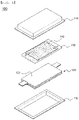
- FIG. 1 is an exploded perspective view of a pouch-shaped battery cell according to the present invention.
- the pouch-shaped battery cell 100 is configured such that an electrode assembly 120, an inner pouch 130, and a penetration member 140 are received in a battery case 110 made of a laminate sheet.
- the battery case 110 shown in FIG. 1 is configured to have a structure in which an upper case and a lower case are separated from each other.
- an integrated battery case configured to have a structure in which the outer perimeter of one side of an upper case and the outer perimeter of one side of a lower case are connected to each other may be used.
- the laminate sheet may be configured to have a structure in which an outer resin layer, an air and moisture blocking metal layer, and a thermally fusible inner resin layer are stacked.
- a polymer resin constituting the outer coating layer may include polyethylene naphthalate (PEN), polyethylene terephthalate (PET), or oriented nylon, which exhibits excellent tensile strength and weather resistance.
- PEN polyethylene naphthalate
- PET polyethylene terephthalate
- oriented nylon which exhibits excellent tensile strength and weather resistance.
- the metal layer may be made of aluminum (Al) or an aluminum alloy in order to exhibit a function of improving strength of the battery case in addition to a function of preventing introduction of foreign matter, such as gas and moisture, or leakage of an electrolytic solution.
- Al aluminum
- Examples of the aluminum alloy may include alloy numbers 8079, 1N30, 8021, 3003, 3004, 3005, 3104, and 3105. These materials may be used alone or in the form of a combination of two or more thereof.
- a polymer resin that exhibits thermal fusibility (thermal adhesiveness), has low hygroscopicity to the electrolytic solution in order to inhibit permeation of the electrolytic solution, and is not expanded or eroded by the electrolytic solution may be used as the inner resin layer. More preferably, the inner resin layer is made of cast polypropylene (CPP).
- CPP cast polypropylene
- the electrode assembly 120 shown in FIG. 1 is a stacked electrode assembly configured to have a structure in which a positive electrode plate and a negative electrode plate are stacked in the state in which a separator is interposed therebetween.
- the structure of the electrode assembly according to the present invention is not limited thereto.
- the electrode assembly may be a stacked and folded type electrode assembly, configured to have a structure in which a plurality of bicells and/or monocells is wound in a state of being disposed on a separation film, a laminated and stacked type electrode assembly, configured to have a structure in which a plurality of bicells and/or monocells is stacked in the state in which a separator is interposed therebetween, or a jelly-roll type electrode assembly, configured to have a structure in which a positive electrode sheet and a negative electrode sheet are wound in the state in which a separator sheet is interposed therebetween.
- a bicell is a battery cell configured to have a structure in which two positive electrodes and one negative electrode are stacked in the state in which separators are interposed therebetween or a battery cell configured to have a structure in which two negative electrodes and one positive electrode are stacked in the state in which separators are interposed therebetween.
- a monocell is a battery cell configured to have a structure in which one positive electrode and one negative electrode are stacked in the state in which a separator is interposed therebetween.
- the penetration member 140 is bent and deformed to discharge an electrolytic solution for replenishment received in the inner pouch 130 when pressure in the battery case increases. That is, it is preferable for the inner pouch 130 and the penetration member 140 to be arranged in tight contact with each other and for the inner pouch 130 and the electrode assembly 120 to be arranged in tight contact with each other such that the penetration member 140 penetrates the inner pouch 130 to move the electrolytic solution for replenishment in a direction toward the electrode assembly.
- the inner pouch 130 may be disposed on the upper surface 121 of the electrode assembly 120, which is an outer surface parallel to the electrodes of the electrode assembly.
- the inner pouch may be disposed on each of the upper surface and the lower surface of the electrode assembly, and the penetration member may be disposed on the outer surface of the inner pouch, in consideration of the amount of the electrolytic solution for replenishment.
- the material for the inner pouch is not particularly restricted as long as the inner pouch is made of a material that does not chemically react with the electrolytic solution and that is easily broken by the penetration member.
- the electrolytic solution for replenishment received in the inner pouch may be easily discharged to the outside, since the inner pouch shrinks due to elastic force thereof.
- the inner pouch shrinks after the electrolytic solution for replenishment is discharged empty space in the battery case increases, whereby pressure in the battery cell may be reduced, and therefore safety of the battery cell may be improved.
- polypropylene PP
- polyethylene PE
- polytetrafluoroethylene PTFE
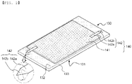
- FIG. 2 is a perspective view of an inner pouch and a penetration member according to a first embodiment, which are the inner pouch and the penetration member shown in FIG. 1 .
- the inner pouch 130 is configured to have a structure including a first surface 131 that faces the electrode assembly 120, a second surface 132 that faces the penetration member 140, the second surface being the outer surface opposite the first surface 131, and a side surface 133 excluding the first surface 131 and the second surface 132, i.e. a rectangular parallelepiped structure.
- each of the first surface 131 and the second surface 132 may include a curved outer perimeter.
- the penetration member 140 includes a piezoelectric element 141 and an electroactive polymer (EAP) pin 142.
- EAP electroactive polymer
- At least one selected from the group consisting of crystal, tourmaline, and Rochelle salt may be used as an example of the piezoelectric element 141.
- mechanical energy may be converted into electrical energy, whereby voltage may be generated.
- the EAP pin is a pin made of an electroactive polymer (EAP), which has a property of shrinking when electricity flows therein.
- EAP pin may be deformed by the voltage generated by the piezoelectric element.
- the battery case may expand due to a heat generation phenomenon and a gas generation phenomenon that occur while the pouch-shaped battery cell is used, whereby pressure in the battery case may be increased.
- the piezoelectric element When the piezoelectric element is pressed by the increased pressure in the battery case, the piezoelectric element may generate voltage. Since the piezoelectric element is electrically connected (not shown) to the EAP pin, the EAP pin may be deformed.
- the piezoelectric element 141 is flat plate shape and is disposed such that the entire portion of the piezoelectric element that faces the second surface 132 of the inner pouch 130 is in tight contact with the second surface 132. Consequently, not only the pressure of gas generated as a result of side reaction between the electrode and the electrolytic solution but also pressure applied by the swollen electrode assembly are transmitted to the piezoelectric element 141 via the inner pouch 130 and act as external force that pushes the piezoelectric element 141.
- a battery pack including a battery cell stack configured to receive a plurality of pouch-shaped battery cells according to the present invention therein and to allow the plurality of pouch-shaped battery cells to be arranged in tight contact with pouch-shaped battery cells adjacent thereto.
- pressure in the pouch-shaped battery cell is several or more times initial pressure in the battery cell.
- the pouch-shaped battery cells are arranged in tight contact with each other in the battery cell stack, swelling of the battery case is limited, whereby pressure in the battery case increased by gas generated therein acts as force that presses the piezoelectric element.
- the through-hole is formed as a result of the EAP pin being deformed and penetrating the inner pouch.
- the electrolytic solution received in the inner pouch moves to the electrode assembly through the through-hole, whereby replenishment of the electrolytic solution is achieved.
- the EAP pin 142 In a normal state, the EAP pin 142 is flat. When pressure in the battery case increases, the EAP pin may be bent and deformed in a direction toward the inner pouch 130.
- the EAP pin 142 includes a coupling portion 142a coupled to the piezoelectric element 141 and a deformation portion 142b configured to be deformed at the time of generation of voltage.
- the deformation portion 142b When the deformation portion 142b is bent perpendicular to the coupling portion 142a, the deformation portion 142b penetrates the second surface 132 of the inner pouch 130, whereby a through-hole is formed in the second surface 132. Consequently, the electrolytic solution for replenishment received in the inner pouch 130 may be discharged in the direction toward the electrode assembly through the through-hole.
- the length of the deformation portion is formed so as to be less than the thickness of the inner pouch.
- FIG. 2 shows the structure in which two EAP pins are disposed at opposite side ends of the piezoelectric element 141.
- a single EAP pin may be coupled to the piezoelectric element, or three or more EAP pins may be coupled to the piezoelectric element in order to rapidly discharge the electrolytic solution for replenishment.
- FIG. 3 is a perspective view of an inner pouch and a penetration member according to a second embodiment.
- a piezoelectric element 241 is flat plate shape and is disposed such that the entire portion of the piezoelectric element that faces a second surface 232 of the inner pouch 230 is in tight contact with the second surface 232.
- An EAP pin 242 includes a coupling portion 242a coupled to the piezoelectric element 241 and a deformation portion 242b configured to be deformed at the time of generation of voltage.
- the coupling portion 242a is located at the upper surface of the flat plate shaped piezoelectric element 241, and the deformation portion 242b is located on the side surface of the piezoelectric element 241 and the side surface 233 of the inner pouch 230.
- the deformation portion 242b is bent perpendicular to the side surface 233 of the inner pouch 230 and penetrates the third surface 233. Consequently, the deformation portion is deformed such that a through-hole is formed in the third surface 233.
- the state in which the deformation portion is deformed is indicated by a dotted line.
- the EAP pin 242 configured such that the deformation portion 242b is disposed so as to penetrate the side surface 233 of the inner pouch 230 is used, there is a merit in that the electrode assembly is not damaged by the bent and deformed EAP pin 242 even though the EAP pin 242 is sharp and long so as to fully penetrate the inner pouch.
- the deformation portion may be longer than the deformation portion of the EAP pin 142 shown in FIG. 2 , whereby a process of forming the through-hole in the inner pouch may be rapidly performed, and a process of injecting the electrolytic solution for replenishment may be performed with improved safety since the side surface of the inner pouch is penetrated.
- FIG. 4 is a perspective view of an inner pouch and a penetration member according to a third embodiment.
- the inner pouch 330 includes a first receiving portion 351 and a second receiving portion 352 partitioned from each other. Consequently, even in the case in which a through-hole is formed in the first receiving portion 351 by a first EAP pin 361 and an electrolytic solution for replenishment is discharged from the first receiving portion 351, the second receiving portion 352 may be maintained in a state in which an electrolytic solution for replenishment is not discharged therefrom.
- the first receiving portion 351 may be maintained in a state in which the electrolytic solution for replenishment is not discharged therefrom. That is, leakage of the electrolytic solution from any one of the first receiving portion 351 and the second receiving portion 352 does not affect the other receiving portion.
- first EAP pin 361 and the second EAP pin 362 may be set so as to have different deformation voltages such that the electrolytic solution is sequentially discharged from the first receiving portion and the second receiving portion.
- the first EAP pin and the second EAP pin may be manufactured using materials having different deformation voltages.
- a piezoelectric element to which the first EAP pin is coupled and a piezoelectric element to which the second EAP pin is coupled may be configured to be separated from each other.
- the pouch-shaped battery cell according to the present invention is configured such that an electrolytic solution that is initially injected includes a film formation additive, and therefore a film is formed on the surface of the positive electrode.
- an electrolytic solution for replenishment that is added includes a film formation additive, however, an additional film is formed, whereby resistance of the pouch-shaped battery cell may increase. Consequently, it is preferable for the electrolytic solution for replenishment to include no film formation additive.
- a pouch-shaped battery cell according to the present invention is configured to have a structure in which, only when pressure in a battery case increases, replenishment of an electrolytic solution is possible, and therefore, when an electrolytic solution initially injected into the pouch-shaped battery cell is depleted and replenishment of the electrolytic solution is necessary, an electrolytic solution for replenishment may move to an electrode assembly.
- the piezoelectric element may generate voltage even due to an increase in pressure in the pouch-shaped battery cell, and therefore the electroactive polymer may be deformed and may penetrate the inner pouch.
Abstract
Description
- This application claims the benefit of priority to
Korean Patent Application No. 2020-0077564 filed on June 25, 2020 - The present invention relates to a pouch-shaped battery cell configured such that replenishment of an electrolytic solution is possible, and more particularly to a pouch-shaped battery cell configured such that replenishment of an electrolytic solution is possible, wherein an inner pouch having an electrolytic solution for replenishment received therein is provided in a battery case, and the electrolytic solution is supplied to an electrode assembly when replenishment of the electrolytic solution is necessary.
- A lithium secondary battery, which is capable of being charged and discharged, is appropriately used as a built-in battery cell, since it is unnecessary to replace a battery cell, and has been applied to various kinds of devices with rapid improvement in stability and rapid increase in capacity thereof.
- For example, the lithium secondary battery has been widely used as an energy source for wireless mobile devices, which are small multifunctional products, or wearable devices, which are worn on bodies, and has also been used as an energy source for electric vehicles and hybrid electric vehicles presented as alternatives to existing gasoline and diesel vehicles, which cause air pollution.
- The lithium secondary battery is configured to have a structure in which an electrode assembly, which includes a lithium-based positive electrode, a negative electrode at which occlusion and discharging of lithium ions reversibly occur, and a separator configured to secure insulation of the positive electrode and the negative electrode, and an electrolytic solution configured to provide a transmission path of the lithium ions are received in a battery case.
- During repeated charging and discharging of the lithium secondary battery, side reaction occurs between the surface of the electrode and the electrolytic solution, whereby the crystal structure of each of the positive electrode and the negative electrode collapses, and the electrolytic solution is depleted. As a result, lifespan of the lithium secondary battery is reduced.
- In particular, mobility of the lithium ions is reduced due to depletion of the electrolytic solution, whereby resistance of the battery cell is increased, and therefore performance of the lithium secondary battery is abruptly deteriorated.
- In order to solve this problem, a method of additionally injecting the electrolytic solution during use of the lithium secondary battery may be considered. In the case in which the battery cell is disassembled in order to add the electrolytic solution, however, there is a high possibility of the electrode being exposed to air, and there is a problem in that it is difficult to seal the disassembled battery cell again.
- As another method, Patent Document 1 discloses an electric device including a surplus electrolytic solution support portion provided at the periphery of a power generation element formed by stacking an electrode layer and an electrolyte layer in order to solve excess and deficiency of an electrolytic solution in an electrode surface due to expansion and contraction of an electrode layer during charging and discharging and a module for electric devices having a pressure transmission medium provided in a space between the surface of the electric device and a case.
- In Patent Document 1, when the electrode layer expands, pressure is transmitted to the pressure transmission medium, and, when the pressure transmitted to the pressure transmission medium is transmitted to the surplus electrolytic solution support portion, an electrolytic solution received in the surplus electrolytic solution support portion is discharged.
- In Patent Document 1, as described above, the pressure transmission medium, as a means configured to discharge the electrolytic solution, is disposed between electrode layers, whereby the capacity of a battery is reduced.
- As another example, Patent Document 2 relates to a pouch-shaped secondary battery having an air cap, as an electrolytic solution replenishment member, provided at an inner wall of the pouch-shaped secondary battery, wherein, when the air cap formed inside a battery case is broken, an electrolytic solution received in the air cap is discharged.
- In Patent Document 2, a process of providing the air cap having the electrolytic solution received therein at the inside of the battery case is separately required, whereby a manufacturing process is complicated. In addition, the air cap is configured to be easily broken, whereby the air cap is broken by external impact even before the electrolytic solution may be depleted, and therefore the electrolytic solution received in the air cap may be discharged. Consequently, it is difficult to adjust the point in time at which the electrolytic solution is to be replenished.
- Therefore, there is a high necessity for technology capable of preventing reduction in capacity of a battery cell while increasing lifespan of the battery cell by the provision of a structure capable of replenishing an electrolytic solution that is depleted during use of a lithium secondary battery and capable of simplifying a manufacturing process.
-
- (Patent Document 1)
Japanese Patent Application Publication No. 2013-134878 (2013.07.08 - (Patent Document 2)
Korean Patent Application Publication No. 2013-0106796 (2013.09.30 - The present invention has been made in view of the above problems, and it is an object of the present invention to provide a pouch-shaped battery cell configured such that replenishment of an electrolytic solution is possible to prevent reduction in lifespan of the pouch-shaped battery cell due to depletion of the electrolytic solution during repeated charging and discharging of the pouch-shaped battery cell.
- A pouch-shaped battery cell according to the present invention to accomplish the above object includes a battery case made of a laminate sheet, an electrode assembly received in the battery case, an inner pouch located on the outer surface of the electrode assembly, the inner pouch having an electrolytic solution for replenishment received therein, and a penetration member configured to penetrate the inner pouch in order to discharge the electrolytic solution for replenishment, wherein the penetration member is configured to be deformed to discharge the electrolytic solution for replenishment received in the inner pouch when a pressure in the battery case increases.
- In the pouch-shaped battery cell according to the present invention, the electrolytic solution for replenishment may include no film formation additive.
- In the pouch-shaped battery cell according to the present invention, the inner pouch may be located on at least one of the upper surface or the lower surface of the electrode assembly, the upper surface and the lower surface being outer surfaces of the electrode assembly parallel to an electrode plate of the electrode assembly.
- In the pouch-shaped battery cell according to the present invention, the inner pouch may include a first surface that faces the electrode assembly, a second surface that faces the penetration member, the second surface being an outer surface of the inner pouch opposite the first surface, and a side surface excluding the first surface and the second surface.
- In the pouch-shaped battery cell according to the present invention, the penetration member may include a piezoelectric element configured to generate a voltage depending on the pressure in the battery case and an electroactive polymer (EAP) pin configured to be deformed by the voltage generated by the piezoelectric element.
- In addition, the EAP pin may be flat in a normal state, and the EAP pin may be bent and deformed in a direction toward the inner pouch when the pressure in the battery case increases.
- In the pouch-shaped battery cell according to the present invention, the piezoelectric element may have a flat plate shape, and the EAP pin may include a coupling portion coupled to the piezoelectric element and a deformation portion configured to be deformed when the voltage increases.
- In the pouch-shaped battery cell according to the present invention, the deformation portion may be configured to be bent perpendicular to the coupling portion and may be configured to penetrate the inner pouch.
- Alternatively, in the pouch-shaped battery cell according to the present invention, the deformation portion may be bent perpendicular to the side surface of the inner pouch and may penetrate the inner pouch.
- In the pouch-shaped battery cell according to the present invention, the penetration member may include a first EAP pin and a second EAP pin connected to a single piezoelectric element.
- In the pouch-shaped battery cell according to the present invention, the inner pouch may include a first receiving portion and a second receiving portion partitioned from each other, and a deformation voltage of the first EAP pin configured to penetrate the first receiving portion and a deformation voltage of the second EAP pin configured to penetrate the second receiving portion may be different from each other.
- In addition, the present invention provides a battery pack including a battery cell stack configured to receive the pouch-shaped battery cell in plural, wherein each of the pouch-shaped battery cells is arranged in tight contact with an adjacent one of the pouch-shaped battery cells in the battery cell stack.
- As is apparent from the above description, a pouch-shaped battery cell according to the present invention is configured to have a structure in which, only when pressure in a battery case increases, replenishment of an electrolytic solution is possible, and therefore, when an electrolytic solution initially injected into the pouch-shaped battery cell is depleted and replenishment of the electrolytic solution is necessary, an electrolytic solution for replenishment may move to an electrode assembly.
- In addition, only a piezoelectric element having an electroactive polymer attached thereto is added together with an inner pouch having an electrolytic solution for replenishment received therein, whereby it is possible to minimize an increase in overall thickness of the pouch-shaped battery cell.
- In addition, since pouch-shaped battery cells are disposed in tight contact with each other to constitute a battery module or a battery pack, the piezoelectric element may generate voltage even due to an increase in pressure in the pouch-shaped battery cell, and therefore the electroactive polymer may be deformed and may penetrate the inner pouch.
- Since, the electrolytic solution for replenishment is added, as described above, it is possible to prevent an increase in resistance of the pouch-shaped battery cell due to depletion of the electrolytic solution, whereby it is possible to provide a pouch-shaped battery cell having improved cycle characteristics.
-
-
FIG. 1 is an exploded perspective view of a pouch-shaped battery cell according to the present invention. -
FIG. 2 is a perspective view of an inner pouch and a penetration member according to a first embodiment. -
FIG. 3 is a perspective view of an inner pouch and a penetration member according to a second embodiment. -
FIG. 4 is a perspective view of an inner pouch and a penetration member according to a third embodiment. - Now, preferred embodiments of the present invention will be described in detail with reference to the accompanying drawings such that the preferred embodiments of the present invention can be easily implemented by a person having ordinary skill in the art to which the present invention pertains. In describing the principle of operation of the preferred embodiments of the present invention in detail, however, a detailed description of known functions and configurations incorporated herein will be omitted when the same may obscure the subject matter of the present invention.
- In addition, the same reference numbers will be used throughout the drawings to refer to parts that perform similar functions or operations. In the case in which one part is said to be connected to another part throughout the specification, not only may the one part be directly connected to the other part, but also, the one part may be indirectly connected to the other part via a further part. In addition, that a certain element is included does not mean that other elements are excluded, but means that such elements may be further included unless mentioned otherwise.
- In addition, a description to embody elements through limitation or addition may be applied to all inventions, unless particularly restricted, and does not limit a specific invention.
- Also, in the description of the invention and the claims of the present application, singular forms are intended to include plural forms unless mentioned otherwise.
- Also, in the description of the invention and the claims of the present application, "or" includes "and" unless mentioned otherwise. Therefore, "including A or B" means three cases, namely, the case including A, the case including B, and the case including A and B.
- In addition, all numeric ranges include the lowest value, the highest value, and all intermediate values therebetween unless the context clearly indicates otherwise.
- Embodiments of the present invention will be described in detail with reference to the accompanying drawings.
-
FIG. 1 is an exploded perspective view of a pouch-shaped battery cell according to the present invention. - Referring to
FIG. 1 , the pouch-shaped battery cell 100 is configured such that anelectrode assembly 120, aninner pouch 130, and apenetration member 140 are received in abattery case 110 made of a laminate sheet. - The
battery case 110 shown inFIG. 1 is configured to have a structure in which an upper case and a lower case are separated from each other. Alternatively, an integrated battery case configured to have a structure in which the outer perimeter of one side of an upper case and the outer perimeter of one side of a lower case are connected to each other may be used. - The laminate sheet may be configured to have a structure in which an outer resin layer, an air and moisture blocking metal layer, and a thermally fusible inner resin layer are stacked.
- It is required for the outer resin layer to exhibit tolerance to an external environment, and therefore more than predetermined tensile strength and weather resistance are necessary. In this aspect, a polymer resin constituting the outer coating layer may include polyethylene naphthalate (PEN), polyethylene terephthalate (PET), or oriented nylon, which exhibits excellent tensile strength and weather resistance.
- The metal layer may be made of aluminum (Al) or an aluminum alloy in order to exhibit a function of improving strength of the battery case in addition to a function of preventing introduction of foreign matter, such as gas and moisture, or leakage of an electrolytic solution. Examples of the aluminum alloy may include alloy numbers 8079, 1N30, 8021, 3003, 3004, 3005, 3104, and 3105. These materials may be used alone or in the form of a combination of two or more thereof.
- A polymer resin that exhibits thermal fusibility (thermal adhesiveness), has low hygroscopicity to the electrolytic solution in order to inhibit permeation of the electrolytic solution, and is not expanded or eroded by the electrolytic solution may be used as the inner resin layer. More preferably, the inner resin layer is made of cast polypropylene (CPP).
- The
electrode assembly 120 shown inFIG. 1 is a stacked electrode assembly configured to have a structure in which a positive electrode plate and a negative electrode plate are stacked in the state in which a separator is interposed therebetween. However, the structure of the electrode assembly according to the present invention is not limited thereto. The electrode assembly may be a stacked and folded type electrode assembly, configured to have a structure in which a plurality of bicells and/or monocells is wound in a state of being disposed on a separation film, a laminated and stacked type electrode assembly, configured to have a structure in which a plurality of bicells and/or monocells is stacked in the state in which a separator is interposed therebetween, or a jelly-roll type electrode assembly, configured to have a structure in which a positive electrode sheet and a negative electrode sheet are wound in the state in which a separator sheet is interposed therebetween. - A bicell is a battery cell configured to have a structure in which two positive electrodes and one negative electrode are stacked in the state in which separators are interposed therebetween or a battery cell configured to have a structure in which two negative electrodes and one positive electrode are stacked in the state in which separators are interposed therebetween. A monocell is a battery cell configured to have a structure in which one positive electrode and one negative electrode are stacked in the state in which a separator is interposed therebetween.
- In the pouch-shaped battery cell according to the present invention, the
penetration member 140 is bent and deformed to discharge an electrolytic solution for replenishment received in theinner pouch 130 when pressure in the battery case increases. That is, it is preferable for theinner pouch 130 and thepenetration member 140 to be arranged in tight contact with each other and for theinner pouch 130 and theelectrode assembly 120 to be arranged in tight contact with each other such that thepenetration member 140 penetrates theinner pouch 130 to move the electrolytic solution for replenishment in a direction toward the electrode assembly. - As shown in
FIG. 1 , therefore, theinner pouch 130 may be disposed on theupper surface 121 of theelectrode assembly 120, which is an outer surface parallel to the electrodes of the electrode assembly. - In addition, unlike what is shown in
FIG. 1 , the inner pouch may be disposed on each of the upper surface and the lower surface of the electrode assembly, and the penetration member may be disposed on the outer surface of the inner pouch, in consideration of the amount of the electrolytic solution for replenishment. - The material for the inner pouch is not particularly restricted as long as the inner pouch is made of a material that does not chemically react with the electrolytic solution and that is easily broken by the penetration member.
- In the case in which an elastic material is used as the inner pouch, the electrolytic solution for replenishment received in the inner pouch may be easily discharged to the outside, since the inner pouch shrinks due to elastic force thereof. In addition, when the inner pouch shrinks after the electrolytic solution for replenishment is discharged, empty space in the battery case increases, whereby pressure in the battery cell may be reduced, and therefore safety of the battery cell may be improved.
- For example, polypropylene (PP), polyethylene (PE), or polytetrafluoroethylene (PTFE) may be used as the material for the inner pouch.
-
FIG. 2 is a perspective view of an inner pouch and a penetration member according to a first embodiment, which are the inner pouch and the penetration member shown inFIG. 1 . - Referring to
FIG. 2 together with theFIG. 1 , theinner pouch 130 is configured to have a structure including afirst surface 131 that faces theelectrode assembly 120, asecond surface 132 that faces thepenetration member 140, the second surface being the outer surface opposite thefirst surface 131, and aside surface 133 excluding thefirst surface 131 and thesecond surface 132, i.e. a rectangular parallelepiped structure. - Alternatively, unlike what is shown in
FIG. 1 , each of thefirst surface 131 and thesecond surface 132 may include a curved outer perimeter. However, it is preferable for each of thefirst surface 131 and thesecond surface 132 to have a size such that the outer perimeter of each of thefirst surface 131 and thesecond surface 132 does not protrude farther than a corresponding one of theupper surface 121 and the lower surface of the electrode assembly. - The
penetration member 140 includes apiezoelectric element 141 and an electroactive polymer (EAP)pin 142. - At least one selected from the group consisting of crystal, tourmaline, and Rochelle salt may be used as an example of the
piezoelectric element 141. When pressure is applied to the piezoelectric element, mechanical energy may be converted into electrical energy, whereby voltage may be generated. - The EAP pin is a pin made of an electroactive polymer (EAP), which has a property of shrinking when electricity flows therein. The EAP pin may be deformed by the voltage generated by the piezoelectric element.
- In a concrete example, the battery case may expand due to a heat generation phenomenon and a gas generation phenomenon that occur while the pouch-shaped battery cell is used, whereby pressure in the battery case may be increased. When the piezoelectric element is pressed by the increased pressure in the battery case, the piezoelectric element may generate voltage. Since the piezoelectric element is electrically connected (not shown) to the EAP pin, the EAP pin may be deformed.
- Specifically, referring to
FIG. 2 , thepiezoelectric element 141 is flat plate shape and is disposed such that the entire portion of the piezoelectric element that faces thesecond surface 132 of theinner pouch 130 is in tight contact with thesecond surface 132. Consequently, not only the pressure of gas generated as a result of side reaction between the electrode and the electrolytic solution but also pressure applied by the swollen electrode assembly are transmitted to thepiezoelectric element 141 via theinner pouch 130 and act as external force that pushes thepiezoelectric element 141. - In a concrete example, it is possible to manufacture a battery pack including a battery cell stack configured to receive a plurality of pouch-shaped battery cells according to the present invention therein and to allow the plurality of pouch-shaped battery cells to be arranged in tight contact with pouch-shaped battery cells adjacent thereto.
- Generally, in the case in which an initial electrolytic solution in a pouch-shaped battery cell is depleted and replenishment of the electrolytic solution is necessary, pressure in the pouch-shaped battery cell is several or more times initial pressure in the battery cell.
- Since the pouch-shaped battery cells are arranged in tight contact with each other in the battery cell stack, swelling of the battery case is limited, whereby pressure in the battery case increased by gas generated therein acts as force that presses the piezoelectric element.
- Consequently, pressure sufficient for the piezoelectric element to generate voltage may be applied to the piezoelectric element, and the EAP pin is deformed by the voltage generated by the piezoelectric element, whereby a through-hole is formed in the inner pouch.
- The through-hole is formed as a result of the EAP pin being deformed and penetrating the inner pouch. The electrolytic solution received in the inner pouch moves to the electrode assembly through the through-hole, whereby replenishment of the electrolytic solution is achieved.
- In a normal state, the
EAP pin 142 is flat. When pressure in the battery case increases, the EAP pin may be bent and deformed in a direction toward theinner pouch 130. TheEAP pin 142 includes acoupling portion 142a coupled to thepiezoelectric element 141 and adeformation portion 142b configured to be deformed at the time of generation of voltage. - When the
deformation portion 142b is bent perpendicular to thecoupling portion 142a, thedeformation portion 142b penetrates thesecond surface 132 of theinner pouch 130, whereby a through-hole is formed in thesecond surface 132. Consequently, the electrolytic solution for replenishment received in theinner pouch 130 may be discharged in the direction toward the electrode assembly through the through-hole. - In order to prevent damage to the electrode assembly due to deformation of the
deformation portion 142b, however, it is preferable for the length of the deformation portion to be formed so as to be less than the thickness of the inner pouch. -
FIG. 2 shows the structure in which two EAP pins are disposed at opposite side ends of thepiezoelectric element 141. Alternatively, a single EAP pin may be coupled to the piezoelectric element, or three or more EAP pins may be coupled to the piezoelectric element in order to rapidly discharge the electrolytic solution for replenishment. However, it is preferable for a plurality of EAP pins to be disposed at different outer perimeters of the piezoelectric element so as to be spaced apart from each other in consideration of the purpose to rapidly supply the electrolytic solution for replenishment to the entire portion of the electrode assembly. -
FIG. 3 is a perspective view of an inner pouch and a penetration member according to a second embodiment. - Referring to
FIG. 3 , apiezoelectric element 241 is flat plate shape and is disposed such that the entire portion of the piezoelectric element that faces asecond surface 232 of theinner pouch 230 is in tight contact with thesecond surface 232. - An
EAP pin 242 includes acoupling portion 242a coupled to thepiezoelectric element 241 and adeformation portion 242b configured to be deformed at the time of generation of voltage. - For the
EAP pin 242 ofFIG. 3 , in a normal state, thecoupling portion 242a is located at the upper surface of the flat plate shapedpiezoelectric element 241, and thedeformation portion 242b is located on the side surface of thepiezoelectric element 241 and theside surface 233 of theinner pouch 230. When pressure is applied to the piezoelectric element and voltage is generated, thedeformation portion 242b is bent perpendicular to theside surface 233 of theinner pouch 230 and penetrates thethird surface 233. Consequently, the deformation portion is deformed such that a through-hole is formed in thethird surface 233. The state in which the deformation portion is deformed is indicated by a dotted line. - In the case in which the
EAP pin 242 configured such that thedeformation portion 242b is disposed so as to penetrate theside surface 233 of theinner pouch 230 is used, there is a merit in that the electrode assembly is not damaged by the bent anddeformed EAP pin 242 even though theEAP pin 242 is sharp and long so as to fully penetrate the inner pouch. - That is, in the case in which the
EAP pin 242 shown inFIG. 3 is used, the deformation portion may be longer than the deformation portion of theEAP pin 142 shown inFIG. 2 , whereby a process of forming the through-hole in the inner pouch may be rapidly performed, and a process of injecting the electrolytic solution for replenishment may be performed with improved safety since the side surface of the inner pouch is penetrated. -
FIG. 4 is a perspective view of an inner pouch and a penetration member according to a third embodiment. - Referring to
FIG. 4 , theinner pouch 330 includes afirst receiving portion 351 and asecond receiving portion 352 partitioned from each other. Consequently, even in the case in which a through-hole is formed in the first receivingportion 351 by afirst EAP pin 361 and an electrolytic solution for replenishment is discharged from the first receivingportion 351, thesecond receiving portion 352 may be maintained in a state in which an electrolytic solution for replenishment is not discharged therefrom. On the other hand, even in the case in which a through-hole is formed in thesecond receiving portion 352 by asecond EAP pin 362 and an electrolytic solution for replenishment is discharged from thesecond receiving portion 352, the first receivingportion 351 may be maintained in a state in which the electrolytic solution for replenishment is not discharged therefrom. That is, leakage of the electrolytic solution from any one of the first receivingportion 351 and thesecond receiving portion 352 does not affect the other receiving portion. - That is, the
first EAP pin 361 and thesecond EAP pin 362 may be set so as to have different deformation voltages such that the electrolytic solution is sequentially discharged from the first receiving portion and the second receiving portion. - For example, the first EAP pin and the second EAP pin may be manufactured using materials having different deformation voltages. Alternatively, a piezoelectric element to which the first EAP pin is coupled and a piezoelectric element to which the second EAP pin is coupled may be configured to be separated from each other.
- Since replenishment of the electrolytic solution is separately performed twice, as described above, it is possible to further improve lifespan characteristics of the pouch-shaped battery cell.
- In a concrete example, the pouch-shaped battery cell according to the present invention is configured such that an electrolytic solution that is initially injected includes a film formation additive, and therefore a film is formed on the surface of the positive electrode. In the case in which an electrolytic solution for replenishment that is added includes a film formation additive, however, an additional film is formed, whereby resistance of the pouch-shaped battery cell may increase. Consequently, it is preferable for the electrolytic solution for replenishment to include no film formation additive.
- Those skilled in the art to which the present invention pertains will appreciate that various applications and modifications are possible within the category of the present invention based on the above description.
-
- 100: Pouch-shaped battery cell
- 110: Battery case
- 120: Electrode assembly
- 121: Upper surface of electrode assembly
- 130, 230, 330: Inner pouches
- 131: First surface
- 132, 232: Second surfaces
- 133, 233: Side surfaces
- 140: Penetration member
- 141, 241: Piezoelectric elements
- 142, 242: Electroactive polymer (EAP) pins
- 142a, 242a: Coupling portions
- 142b, 242b: Deformation portions
- 351: First receiving portion
- 352: Second receiving portion
- 361: First EAP pin
- 362: Second EAP pin
- As is apparent from the above description, a pouch-shaped battery cell according to the present invention is configured to have a structure in which, only when pressure in a battery case increases, replenishment of an electrolytic solution is possible, and therefore, when an electrolytic solution initially injected into the pouch-shaped battery cell is depleted and replenishment of the electrolytic solution is necessary, an electrolytic solution for replenishment may move to an electrode assembly.
- In addition, only a piezoelectric element having an electroactive polymer attached thereto is added together with an inner pouch having an electrolytic solution for replenishment received therein, whereby it is possible to minimize an increase in overall thickness of the pouch-shaped battery cell.
- In addition, since pouch-shaped battery cells are disposed in tight contact with each other to constitute a battery module or a battery pack, the piezoelectric element may generate voltage even due to an increase in pressure in the pouch-shaped battery cell, and therefore the electroactive polymer may be deformed and may penetrate the inner pouch.
- Consequently, it is possible to prevent an increase in resistance of the pouch-shaped battery cell through addition of the electrolytic solution for replenishment, whereby it is possible to provide a pouch-shaped battery cell having improved cycle characteristics.
Claims (12)
- A pouch-shaped battery cell comprising:a battery case made of a laminate sheet;an electrode assembly received in the battery case;an inner pouch located on an outer surface of the electrode assembly, the inner pouch having an electrolytic solution for replenishment received therein; anda penetration member configured to penetrate the inner pouch in order to discharge the electrolytic solution for replenishment,wherein the penetration member is configured to be deformed to discharge the electrolytic solution for replenishment received in the inner pouch when a pressure in the battery case increases.
- The pouch-shaped battery cell according to claim 1, wherein the electrolytic solution for replenishment comprises no film formation additive.
- The pouch-shaped battery cell according to claim 1, wherein the inner pouch is located on at least one of an upper surface or a lower surface of the electrode assembly, the upper surface and the lower surface being outer surfaces of the electrode assembly parallel to an electrode plate of the electrode assembly.
- The pouch-shaped battery cell according to claim 1, wherein the inner pouch comprises:a first surface that faces the electrode assembly;a second surface that faces the penetration member, the second surface being an outer surface of the inner pouch opposite the first surface; anda side surface excluding the first surface and the second surface.
- The pouch-shaped battery cell according to claim 4, wherein the penetration member comprises:A piezoelectric element configured to generate a voltage depending on the pressure in the battery case; andan electroactive polymer (EAP) pin configured to be deformed by the voltage generated by the piezoelectric element.
- The pouch-shaped battery cell according to claim 5, wherein the EAP pin is flat in a normal state, and the EAP pin is bent and deformed in a direction toward the inner pouch when the pressure in the battery case increases.
- The pouch-shaped battery cell according to claim 5, wherein the piezoelectric element has a flat plate shape, and the EAP pin comprises a coupling portion coupled to the piezoelectric element and a deformation portion configured to be deformed when the voltage increases.
- The pouch-shaped battery cell according to claim 7, wherein the deformation portion is configured to be bent perpendicular to the coupling portion and is configured to penetrate the inner pouch.
- The pouch-shaped battery cell according to claim 7, wherein the deformation portion is configured to be bent perpendicular to the side surface of the inner pouch and is configured to penetrate the inner pouch.
- The pouch-shaped battery cell according to claim 5, wherein the penetration member comprises a first EAP pin and a second EAP pin connected to a single piezoelectric element.
- The pouch-shaped battery cell according to claim 10, whereinthe inner pouch comprises a first receiving portion and a second receiving portion partitioned from each other, anda deformation voltage of the first EAP pin configured to penetrate the first receiving portion and a deformation voltage of the second EAP pin configured to penetrate the second receiving portion are different from each other.
- A battery pack comprising a battery cell stack configured to receive the pouch-shaped battery cell according to any one of claims 1 to 11 in plural, wherein each of the pouch-shaped battery cells is arranged in tight contact with an adjacent one of the pouch-shaped battery cells in the battery cell stack.
Applications Claiming Priority (2)
| Application Number | Priority Date | Filing Date | Title |
|---|---|---|---|
| KR1020200077564A KR20220000068A (en) | 2020-06-25 | 2020-06-25 | Pouch-type Battery Cell capable of Replenishing Electrolyte |
| PCT/KR2021/007926 WO2021261932A1 (en) | 2020-06-25 | 2021-06-24 | Pouch-type battery cell allowing supplementing of electrolyte |
Publications (2)
| Publication Number | Publication Date |
|---|---|
| EP4068461A1 true EP4068461A1 (en) | 2022-10-05 |
| EP4068461A4 EP4068461A4 (en) | 2023-07-26 |
Family
ID=79281521
Family Applications (1)
| Application Number | Title | Priority Date | Filing Date |
|---|---|---|---|
| EP21828865.2A Pending EP4068461A4 (en) | 2020-06-25 | 2021-06-24 | Pouch-type battery cell allowing supplementing of electrolyte |
Country Status (6)
| Country | Link |
|---|---|
| US (1) | US20230307807A1 (en) |
| EP (1) | EP4068461A4 (en) |
| JP (1) | JP7418899B2 (en) |
| KR (1) | KR20220000068A (en) |
| CN (1) | CN114730926A (en) |
| WO (1) | WO2021261932A1 (en) |
Families Citing this family (2)
| Publication number | Priority date | Publication date | Assignee | Title |
|---|---|---|---|---|
| KR20230141117A (en) * | 2022-03-31 | 2023-10-10 | 주식회사 엘지에너지솔루션 | Battery case and secondary battery |
| WO2024049225A1 (en) * | 2022-09-01 | 2024-03-07 | 주식회사 엘지에너지솔루션 | Secondary battery and device including same |
Family Cites Families (13)
| Publication number | Priority date | Publication date | Assignee | Title |
|---|---|---|---|---|
| US3445295A (en) * | 1966-09-30 | 1969-05-20 | Honeywell Inc | Ammonia battery |
| KR20100051403A (en) * | 2008-11-07 | 2010-05-17 | 에너그린(주) | Secondary battery including auto supplement solution supplying system |
| JP5603649B2 (en) * | 2010-05-10 | 2014-10-08 | シャープ株式会社 | Secondary battery and solar power generation system, wind power generation system, and vehicle equipped with the secondary battery |
| JP5346839B2 (en) * | 2010-02-15 | 2013-11-20 | シャープ株式会社 | Lithium ion secondary battery |
| KR101313070B1 (en) * | 2010-03-23 | 2013-09-30 | 주식회사 엘지화학 | A case for lithium secondary battery and lithium secondary battery comprising the same |
| JP2012243672A (en) * | 2011-05-23 | 2012-12-10 | Nec Corp | Lithium ion secondary battery |
| JP2013134878A (en) | 2011-12-26 | 2013-07-08 | Nissan Motor Co Ltd | Module for electric device |
| KR101459885B1 (en) | 2012-03-20 | 2014-11-07 | 주식회사 엘지화학 | Pouch-type battery having a air-cap comprising a liquid electrolyte |
| KR101732697B1 (en) * | 2014-09-16 | 2017-05-04 | 에스케이이노베이션 주식회사 | Lithium secondary battery |
| KR101936074B1 (en) * | 2015-05-12 | 2019-01-09 | 주식회사 엘지화학 | Battery Cell Comprising Electrolyte-Containing Member for Supplying Electrolyte |
| EP3367912B1 (en) * | 2015-10-27 | 2018-12-26 | Koninklijke Philips N.V. | Medical probe for ultrasound imaging |
| KR102133048B1 (en) * | 2016-12-01 | 2020-07-13 | 주식회사 엘지화학 | Pouch-typed Secondary Battery Containing Electrolyte Holding Part |
| CN110942422A (en) | 2018-09-21 | 2020-03-31 | 北京市商汤科技开发有限公司 | Image processing method and device and computer storage medium |
-
2020
- 2020-06-25 KR KR1020200077564A patent/KR20220000068A/en active Search and Examination
-
2021
- 2021-06-24 CN CN202180006520.1A patent/CN114730926A/en active Pending
- 2021-06-24 US US17/793,825 patent/US20230307807A1/en active Pending
- 2021-06-24 WO PCT/KR2021/007926 patent/WO2021261932A1/en unknown
- 2021-06-24 JP JP2022535206A patent/JP7418899B2/en active Active
- 2021-06-24 EP EP21828865.2A patent/EP4068461A4/en active Pending
Also Published As
| Publication number | Publication date |
|---|---|
| KR20220000068A (en) | 2022-01-03 |
| CN114730926A (en) | 2022-07-08 |
| JP2023507304A (en) | 2023-02-22 |
| JP7418899B2 (en) | 2024-01-22 |
| WO2021261932A1 (en) | 2021-12-30 |
| US20230307807A1 (en) | 2023-09-28 |
| EP4068461A4 (en) | 2023-07-26 |
Similar Documents
| Publication | Publication Date | Title |
|---|---|---|
| US11437683B2 (en) | Battery cell of venting structure using taping | |
| CN111033799B (en) | Pouch type secondary battery having gas discharge member | |
| US11046206B2 (en) | Battery module with short-circuit unit, and battery pack and vehicle including the same | |
| EP3382771A1 (en) | Secondary battery pouch exterior material, pouch type secondary battery using same, and manufacturing method therefor | |
| JP4920111B2 (en) | Pouch type secondary battery | |
| US20150303425A1 (en) | Secondary battery module | |
| EP3676888B1 (en) | Lead tab for a battery terminal | |
| EP2587566A2 (en) | Rechargeable battery with improved safety | |
| US9653749B2 (en) | Secondary battery and secondary battery pack having the same | |
| EP3486967B1 (en) | Battery cell comprising electrode lead facing outer surface of electrode assembly | |
| EP4068461A1 (en) | Pouch-type battery cell allowing supplementing of electrolyte | |
| US11522249B2 (en) | Pouch-type battery cell including venting member and battery pack including the same | |
| US20230052005A1 (en) | Electrode assembly including disconnection preventing layer and method for manufacturing the same | |
| EP3392933B1 (en) | Secondary battery and method for supplementing electrolyte of secondary battery | |
| KR101533993B1 (en) | Battery Module Having Sheet Member and Film Member | |
| CN111837255B (en) | Secondary battery and battery module | |
| KR20200056376A (en) | Secondary Battery Module | |
| KR20190082180A (en) | Secondary Battery Module | |
| KR20190112582A (en) | Battery cell cartridge having uniformity surface pressure | |
| US20240154217A1 (en) | Secondary Battery, Manufacturing Method Thereof, and Device Including the Same | |
| KR20220067981A (en) | Exterior material for flaxible battery | |
| CN115699443A (en) | Battery cell including electrode tab formed with stress relief portion |
Legal Events
| Date | Code | Title | Description |
|---|---|---|---|
| STAA | Information on the status of an ep patent application or granted ep patent |
Free format text: STATUS: THE INTERNATIONAL PUBLICATION HAS BEEN MADE |
|
| PUAI | Public reference made under article 153(3) epc to a published international application that has entered the european phase |
Free format text: ORIGINAL CODE: 0009012 |
|
| STAA | Information on the status of an ep patent application or granted ep patent |
Free format text: STATUS: REQUEST FOR EXAMINATION WAS MADE |
|
| 17P | Request for examination filed |
Effective date: 20220628 |
|
| AK | Designated contracting states |
Kind code of ref document: A1 Designated state(s): AL AT BE BG CH CY CZ DE DK EE ES FI FR GB GR HR HU IE IS IT LI LT LU LV MC MK MT NL NO PL PT RO RS SE SI SK SM TR |
|
| A4 | Supplementary search report drawn up and despatched |
Effective date: 20230623 |
|
| RIC1 | Information provided on ipc code assigned before grant |
Ipc: H01M 50/10 20210101ALI20230619BHEP Ipc: H01M 50/609 20210101ALI20230619BHEP Ipc: H01M 50/211 20210101ALI20230619BHEP Ipc: H01M 50/105 20210101ALI20230619BHEP Ipc: H01M 50/682 20210101ALI20230619BHEP Ipc: H01M 50/618 20210101ALI20230619BHEP Ipc: H01M 50/124 20210101ALI20230619BHEP Ipc: H01M 50/116 20210101ALI20230619BHEP Ipc: H01M 50/60 20210101ALI20230619BHEP Ipc: H01M 50/691 20210101ALI20230619BHEP Ipc: H01M 10/42 20060101AFI20230619BHEP |
|
| DAV | Request for validation of the european patent (deleted) | ||
| DAX | Request for extension of the european patent (deleted) |