EP4067937A1 - Verfahren zur erkennung von hindernisobjekten sowie zur prognose der veränderung der position bekannter hindernisobjekte anhand von signalen mehrerer sensoren und zur kompression sowie dekompression von zu den obigen zwecken verwendeten sensorsignalen - Google Patents
Verfahren zur erkennung von hindernisobjekten sowie zur prognose der veränderung der position bekannter hindernisobjekte anhand von signalen mehrerer sensoren und zur kompression sowie dekompression von zu den obigen zwecken verwendeten sensorsignalen Download PDFInfo
- Publication number
- EP4067937A1 EP4067937A1 EP22175103.5A EP22175103A EP4067937A1 EP 4067937 A1 EP4067937 A1 EP 4067937A1 EP 22175103 A EP22175103 A EP 22175103A EP 4067937 A1 EP4067937 A1 EP 4067937A1
- Authority
- EP
- European Patent Office
- Prior art keywords
- signal
- feature vector
- sensor
- data
- objects
- Prior art date
- Legal status (The legal status is an assumption and is not a legal conclusion. Google has not performed a legal analysis and makes no representation as to the accuracy of the status listed.)
- Pending
Links
- 238000000034 method Methods 0.000 title claims abstract description 198
- 230000006837 decompression Effects 0.000 title claims abstract description 56
- 238000007906 compression Methods 0.000 title claims abstract description 40
- 230000006835 compression Effects 0.000 title claims abstract description 40
- 230000008859 change Effects 0.000 title description 41
- 230000005540 biological transmission Effects 0.000 claims abstract description 167
- 239000013598 vector Substances 0.000 claims description 815
- 230000001537 neural effect Effects 0.000 claims description 133
- 238000012545 processing Methods 0.000 claims description 117
- 238000001514 detection method Methods 0.000 claims description 93
- 239000000872 buffer Substances 0.000 claims description 60
- 238000005259 measurement Methods 0.000 claims description 53
- 238000000605 extraction Methods 0.000 claims description 47
- 238000013528 artificial neural network Methods 0.000 claims description 44
- 230000008569 process Effects 0.000 claims description 31
- 230000009466 transformation Effects 0.000 claims description 23
- 230000002829 reductive effect Effects 0.000 claims description 7
- 230000001186 cumulative effect Effects 0.000 claims description 2
- GNFTZDOKVXKIBK-UHFFFAOYSA-N 3-(2-methoxyethoxy)benzohydrazide Chemical compound COCCOC1=CC=CC(C(=O)NN)=C1 GNFTZDOKVXKIBK-UHFFFAOYSA-N 0.000 claims 1
- 238000002604 ultrasonography Methods 0.000 abstract description 50
- 230000015572 biosynthetic process Effects 0.000 abstract description 13
- 230000001502 supplementing effect Effects 0.000 abstract description 2
- 238000004393 prognosis Methods 0.000 description 88
- 230000015654 memory Effects 0.000 description 68
- 238000011156 evaluation Methods 0.000 description 33
- 230000000875 corresponding effect Effects 0.000 description 24
- 238000013144 data compression Methods 0.000 description 24
- 230000002457 bidirectional effect Effects 0.000 description 20
- 230000036961 partial effect Effects 0.000 description 20
- 238000002592 echocardiography Methods 0.000 description 19
- 230000002123 temporal effect Effects 0.000 description 19
- 230000005484 gravity Effects 0.000 description 17
- 230000003595 spectral effect Effects 0.000 description 17
- 238000005070 sampling Methods 0.000 description 14
- 101150053531 MNN1 gene Proteins 0.000 description 13
- 230000006870 function Effects 0.000 description 13
- 239000011159 matrix material Substances 0.000 description 12
- 238000003062 neural network model Methods 0.000 description 12
- 101100184475 Candida albicans (strain SC5314 / ATCC MYA-2876) MNN24 gene Proteins 0.000 description 11
- 101000686031 Homo sapiens Proto-oncogene tyrosine-protein kinase ROS Proteins 0.000 description 11
- 101100488151 Kluyveromyces lactis (strain ATCC 8585 / CBS 2359 / DSM 70799 / NBRC 1267 / NRRL Y-1140 / WM37) YEA4 gene Proteins 0.000 description 11
- 101150093457 MNN2 gene Proteins 0.000 description 11
- 102100023347 Proto-oncogene tyrosine-protein kinase ROS Human genes 0.000 description 11
- 230000002596 correlated effect Effects 0.000 description 10
- 238000012546 transfer Methods 0.000 description 10
- 238000004088 simulation Methods 0.000 description 9
- 238000010586 diagram Methods 0.000 description 8
- 230000007704 transition Effects 0.000 description 8
- 101100091482 Caenorhabditis elegans rop-1 gene Proteins 0.000 description 7
- 101100390736 Danio rerio fign gene Proteins 0.000 description 6
- 101100390738 Mus musculus Fign gene Proteins 0.000 description 6
- 238000010276 construction Methods 0.000 description 6
- 230000011664 signaling Effects 0.000 description 6
- 238000012360 testing method Methods 0.000 description 6
- 238000004458 analytical method Methods 0.000 description 5
- 230000008901 benefit Effects 0.000 description 5
- 238000004364 calculation method Methods 0.000 description 5
- 230000001419 dependent effect Effects 0.000 description 5
- 230000004927 fusion Effects 0.000 description 5
- 230000009467 reduction Effects 0.000 description 5
- 238000012549 training Methods 0.000 description 5
- 230000000694 effects Effects 0.000 description 4
- 238000001914 filtration Methods 0.000 description 4
- 230000010354 integration Effects 0.000 description 4
- 238000013507 mapping Methods 0.000 description 4
- 238000012913 prioritisation Methods 0.000 description 4
- 238000013139 quantization Methods 0.000 description 4
- 210000002023 somite Anatomy 0.000 description 4
- 101100396523 Caenorhabditis elegans ife-1 gene Proteins 0.000 description 3
- 101100072264 Caenorhabditis elegans ife-2 gene Proteins 0.000 description 3
- 238000004422 calculation algorithm Methods 0.000 description 3
- 238000005352 clarification Methods 0.000 description 3
- 238000011161 development Methods 0.000 description 3
- 238000009826 distribution Methods 0.000 description 3
- 239000003623 enhancer Substances 0.000 description 3
- 230000006872 improvement Effects 0.000 description 3
- 238000012804 iterative process Methods 0.000 description 3
- 238000003909 pattern recognition Methods 0.000 description 3
- 239000000047 product Substances 0.000 description 3
- 230000004044 response Effects 0.000 description 3
- HEFNNWSXXWATRW-UHFFFAOYSA-N Ibuprofen Chemical compound CC(C)CC1=CC=C(C(C)C(O)=O)C=C1 HEFNNWSXXWATRW-UHFFFAOYSA-N 0.000 description 2
- 238000013459 approach Methods 0.000 description 2
- 238000013473 artificial intelligence Methods 0.000 description 2
- 230000001174 ascending effect Effects 0.000 description 2
- 238000004891 communication Methods 0.000 description 2
- 230000001276 controlling effect Effects 0.000 description 2
- 230000004069 differentiation Effects 0.000 description 2
- 238000010606 normalization Methods 0.000 description 2
- 238000005457 optimization Methods 0.000 description 2
- 230000010076 replication Effects 0.000 description 2
- 230000008054 signal transmission Effects 0.000 description 2
- 238000007619 statistical method Methods 0.000 description 2
- 101710130024 1-aminocyclopropane-1-carboxylate oxidase Proteins 0.000 description 1
- 101710098417 1-aminocyclopropane-1-carboxylate oxidase 1 Proteins 0.000 description 1
- 101710098416 1-aminocyclopropane-1-carboxylate oxidase 2 Proteins 0.000 description 1
- 101710098415 1-aminocyclopropane-1-carboxylate oxidase 3 Proteins 0.000 description 1
- 101710098411 1-aminocyclopropane-1-carboxylate oxidase 4 Proteins 0.000 description 1
- 101710163931 2-oxoglutarate-dependent ethylene/succinate-forming enzyme Proteins 0.000 description 1
- 241001136792 Alle Species 0.000 description 1
- FGUUSXIOTUKUDN-IBGZPJMESA-N C1(=CC=CC=C1)N1C2=C(NC([C@H](C1)NC=1OC(=NN=1)C1=CC=CC=C1)=O)C=CC=C2 Chemical compound C1(=CC=CC=C1)N1C2=C(NC([C@H](C1)NC=1OC(=NN=1)C1=CC=CC=C1)=O)C=CC=C2 FGUUSXIOTUKUDN-IBGZPJMESA-N 0.000 description 1
- 101100328519 Caenorhabditis elegans cnt-2 gene Proteins 0.000 description 1
- 101100063432 Caenorhabditis elegans dim-1 gene Proteins 0.000 description 1
- 206010012335 Dependence Diseases 0.000 description 1
- 101150005287 EPS1 gene Proteins 0.000 description 1
- 241000027294 Fusi Species 0.000 description 1
- 206010028916 Neologism Diseases 0.000 description 1
- 230000003321 amplification Effects 0.000 description 1
- 239000002131 composite material Substances 0.000 description 1
- 230000003247 decreasing effect Effects 0.000 description 1
- 238000013135 deep learning Methods 0.000 description 1
- 230000007547 defect Effects 0.000 description 1
- 230000007812 deficiency Effects 0.000 description 1
- 238000009795 derivation Methods 0.000 description 1
- 238000013461 design Methods 0.000 description 1
- 230000009977 dual effect Effects 0.000 description 1
- 230000007613 environmental effect Effects 0.000 description 1
- 239000000284 extract Substances 0.000 description 1
- 230000003993 interaction Effects 0.000 description 1
- 238000011835 investigation Methods 0.000 description 1
- 238000012886 linear function Methods 0.000 description 1
- 238000007477 logistic regression Methods 0.000 description 1
- 238000010801 machine learning Methods 0.000 description 1
- 238000004519 manufacturing process Methods 0.000 description 1
- 230000006855 networking Effects 0.000 description 1
- 238000003199 nucleic acid amplification method Methods 0.000 description 1
- 230000003287 optical effect Effects 0.000 description 1
- 230000003071 parasitic effect Effects 0.000 description 1
- 230000000737 periodic effect Effects 0.000 description 1
- 230000002688 persistence Effects 0.000 description 1
- 230000010363 phase shift Effects 0.000 description 1
- 230000001681 protective effect Effects 0.000 description 1
- 238000011002 quantification Methods 0.000 description 1
- 230000002441 reversible effect Effects 0.000 description 1
- 238000001228 spectrum Methods 0.000 description 1
- 238000003860 storage Methods 0.000 description 1
- 239000013589 supplement Substances 0.000 description 1
- 230000001960 triggered effect Effects 0.000 description 1
- 238000009827 uniform distribution Methods 0.000 description 1
Images


Classifications
-
- G—PHYSICS
- G01—MEASURING; TESTING
- G01S—RADIO DIRECTION-FINDING; RADIO NAVIGATION; DETERMINING DISTANCE OR VELOCITY BY USE OF RADIO WAVES; LOCATING OR PRESENCE-DETECTING BY USE OF THE REFLECTION OR RERADIATION OF RADIO WAVES; ANALOGOUS ARRANGEMENTS USING OTHER WAVES
- G01S15/00—Systems using the reflection or reradiation of acoustic waves, e.g. sonar systems
- G01S15/88—Sonar systems specially adapted for specific applications
- G01S15/93—Sonar systems specially adapted for specific applications for anti-collision purposes
- G01S15/931—Sonar systems specially adapted for specific applications for anti-collision purposes of land vehicles
-
- G—PHYSICS
- G01—MEASURING; TESTING
- G01N—INVESTIGATING OR ANALYSING MATERIALS BY DETERMINING THEIR CHEMICAL OR PHYSICAL PROPERTIES
- G01N3/00—Investigating strength properties of solid materials by application of mechanical stress
- G01N3/08—Investigating strength properties of solid materials by application of mechanical stress by applying steady tensile or compressive forces
-
- G—PHYSICS
- G01—MEASURING; TESTING
- G01S—RADIO DIRECTION-FINDING; RADIO NAVIGATION; DETERMINING DISTANCE OR VELOCITY BY USE OF RADIO WAVES; LOCATING OR PRESENCE-DETECTING BY USE OF THE REFLECTION OR RERADIATION OF RADIO WAVES; ANALOGOUS ARRANGEMENTS USING OTHER WAVES
- G01S15/00—Systems using the reflection or reradiation of acoustic waves, e.g. sonar systems
- G01S15/66—Sonar tracking systems
-
- G—PHYSICS
- G01—MEASURING; TESTING
- G01S—RADIO DIRECTION-FINDING; RADIO NAVIGATION; DETERMINING DISTANCE OR VELOCITY BY USE OF RADIO WAVES; LOCATING OR PRESENCE-DETECTING BY USE OF THE REFLECTION OR RERADIATION OF RADIO WAVES; ANALOGOUS ARRANGEMENTS USING OTHER WAVES
- G01S15/00—Systems using the reflection or reradiation of acoustic waves, e.g. sonar systems
- G01S15/86—Combinations of sonar systems with lidar systems; Combinations of sonar systems with systems not using wave reflection
-
- G—PHYSICS
- G01—MEASURING; TESTING
- G01S—RADIO DIRECTION-FINDING; RADIO NAVIGATION; DETERMINING DISTANCE OR VELOCITY BY USE OF RADIO WAVES; LOCATING OR PRESENCE-DETECTING BY USE OF THE REFLECTION OR RERADIATION OF RADIO WAVES; ANALOGOUS ARRANGEMENTS USING OTHER WAVES
- G01S15/00—Systems using the reflection or reradiation of acoustic waves, e.g. sonar systems
- G01S15/87—Combinations of sonar systems
- G01S15/876—Combination of several spaced transmitters or receivers of known location for determining the position of a transponder or a reflector
-
- G—PHYSICS
- G01—MEASURING; TESTING
- G01S—RADIO DIRECTION-FINDING; RADIO NAVIGATION; DETERMINING DISTANCE OR VELOCITY BY USE OF RADIO WAVES; LOCATING OR PRESENCE-DETECTING BY USE OF THE REFLECTION OR RERADIATION OF RADIO WAVES; ANALOGOUS ARRANGEMENTS USING OTHER WAVES
- G01S7/00—Details of systems according to groups G01S13/00, G01S15/00, G01S17/00
- G01S7/003—Transmission of data between radar, sonar or lidar systems and remote stations
-
- G—PHYSICS
- G01—MEASURING; TESTING
- G01S—RADIO DIRECTION-FINDING; RADIO NAVIGATION; DETERMINING DISTANCE OR VELOCITY BY USE OF RADIO WAVES; LOCATING OR PRESENCE-DETECTING BY USE OF THE REFLECTION OR RERADIATION OF RADIO WAVES; ANALOGOUS ARRANGEMENTS USING OTHER WAVES
- G01S7/00—Details of systems according to groups G01S13/00, G01S15/00, G01S17/00
- G01S7/52—Details of systems according to groups G01S13/00, G01S15/00, G01S17/00 of systems according to group G01S15/00
- G01S7/523—Details of pulse systems
- G01S7/526—Receivers
- G01S7/53—Means for transforming coordinates or for evaluating data, e.g. using computers
- G01S7/533—Data rate converters
-
- G—PHYSICS
- G01—MEASURING; TESTING
- G01S—RADIO DIRECTION-FINDING; RADIO NAVIGATION; DETERMINING DISTANCE OR VELOCITY BY USE OF RADIO WAVES; LOCATING OR PRESENCE-DETECTING BY USE OF THE REFLECTION OR RERADIATION OF RADIO WAVES; ANALOGOUS ARRANGEMENTS USING OTHER WAVES
- G01S7/00—Details of systems according to groups G01S13/00, G01S15/00, G01S17/00
- G01S7/52—Details of systems according to groups G01S13/00, G01S15/00, G01S17/00 of systems according to group G01S15/00
- G01S7/534—Details of non-pulse systems
-
- G—PHYSICS
- G01—MEASURING; TESTING
- G01S—RADIO DIRECTION-FINDING; RADIO NAVIGATION; DETERMINING DISTANCE OR VELOCITY BY USE OF RADIO WAVES; LOCATING OR PRESENCE-DETECTING BY USE OF THE REFLECTION OR RERADIATION OF RADIO WAVES; ANALOGOUS ARRANGEMENTS USING OTHER WAVES
- G01S7/00—Details of systems according to groups G01S13/00, G01S15/00, G01S17/00
- G01S7/52—Details of systems according to groups G01S13/00, G01S15/00, G01S17/00 of systems according to group G01S15/00
- G01S7/539—Details of systems according to groups G01S13/00, G01S15/00, G01S17/00 of systems according to group G01S15/00 using analysis of echo signal for target characterisation; Target signature; Target cross-section
-
- G—PHYSICS
- G06—COMPUTING; CALCULATING OR COUNTING
- G06N—COMPUTING ARRANGEMENTS BASED ON SPECIFIC COMPUTATIONAL MODELS
- G06N3/00—Computing arrangements based on biological models
- G06N3/02—Neural networks
- G06N3/04—Architecture, e.g. interconnection topology
-
- G—PHYSICS
- G06—COMPUTING; CALCULATING OR COUNTING
- G06N—COMPUTING ARRANGEMENTS BASED ON SPECIFIC COMPUTATIONAL MODELS
- G06N3/00—Computing arrangements based on biological models
- G06N3/02—Neural networks
- G06N3/04—Architecture, e.g. interconnection topology
- G06N3/044—Recurrent networks, e.g. Hopfield networks
-
- G—PHYSICS
- G06—COMPUTING; CALCULATING OR COUNTING
- G06N—COMPUTING ARRANGEMENTS BASED ON SPECIFIC COMPUTATIONAL MODELS
- G06N3/00—Computing arrangements based on biological models
- G06N3/02—Neural networks
- G06N3/04—Architecture, e.g. interconnection topology
- G06N3/045—Combinations of networks
-
- G—PHYSICS
- G06—COMPUTING; CALCULATING OR COUNTING
- G06N—COMPUTING ARRANGEMENTS BASED ON SPECIFIC COMPUTATIONAL MODELS
- G06N3/00—Computing arrangements based on biological models
- G06N3/02—Neural networks
- G06N3/08—Learning methods
-
- H—ELECTRICITY
- H03—ELECTRONIC CIRCUITRY
- H03M—CODING; DECODING; CODE CONVERSION IN GENERAL
- H03M7/00—Conversion of a code where information is represented by a given sequence or number of digits to a code where the same, similar or subset of information is represented by a different sequence or number of digits
- H03M7/30—Compression; Expansion; Suppression of unnecessary data, e.g. redundancy reduction
- H03M7/3082—Vector coding
-
- G—PHYSICS
- G01—MEASURING; TESTING
- G01S—RADIO DIRECTION-FINDING; RADIO NAVIGATION; DETERMINING DISTANCE OR VELOCITY BY USE OF RADIO WAVES; LOCATING OR PRESENCE-DETECTING BY USE OF THE REFLECTION OR RERADIATION OF RADIO WAVES; ANALOGOUS ARRANGEMENTS USING OTHER WAVES
- G01S13/00—Systems using the reflection or reradiation of radio waves, e.g. radar systems; Analogous systems using reflection or reradiation of waves whose nature or wavelength is irrelevant or unspecified
- G01S13/66—Radar-tracking systems; Analogous systems
- G01S13/72—Radar-tracking systems; Analogous systems for two-dimensional tracking, e.g. combination of angle and range tracking, track-while-scan radar
- G01S13/723—Radar-tracking systems; Analogous systems for two-dimensional tracking, e.g. combination of angle and range tracking, track-while-scan radar by using numerical data
-
- G—PHYSICS
- G01—MEASURING; TESTING
- G01S—RADIO DIRECTION-FINDING; RADIO NAVIGATION; DETERMINING DISTANCE OR VELOCITY BY USE OF RADIO WAVES; LOCATING OR PRESENCE-DETECTING BY USE OF THE REFLECTION OR RERADIATION OF RADIO WAVES; ANALOGOUS ARRANGEMENTS USING OTHER WAVES
- G01S13/00—Systems using the reflection or reradiation of radio waves, e.g. radar systems; Analogous systems using reflection or reradiation of waves whose nature or wavelength is irrelevant or unspecified
- G01S13/86—Combinations of radar systems with non-radar systems, e.g. sonar, direction finder
- G01S13/862—Combination of radar systems with sonar systems
-
- G—PHYSICS
- G01—MEASURING; TESTING
- G01S—RADIO DIRECTION-FINDING; RADIO NAVIGATION; DETERMINING DISTANCE OR VELOCITY BY USE OF RADIO WAVES; LOCATING OR PRESENCE-DETECTING BY USE OF THE REFLECTION OR RERADIATION OF RADIO WAVES; ANALOGOUS ARRANGEMENTS USING OTHER WAVES
- G01S17/00—Systems using the reflection or reradiation of electromagnetic waves other than radio waves, e.g. lidar systems
- G01S17/66—Tracking systems using electromagnetic waves other than radio waves
-
- G—PHYSICS
- G01—MEASURING; TESTING
- G01S—RADIO DIRECTION-FINDING; RADIO NAVIGATION; DETERMINING DISTANCE OR VELOCITY BY USE OF RADIO WAVES; LOCATING OR PRESENCE-DETECTING BY USE OF THE REFLECTION OR RERADIATION OF RADIO WAVES; ANALOGOUS ARRANGEMENTS USING OTHER WAVES
- G01S17/00—Systems using the reflection or reradiation of electromagnetic waves other than radio waves, e.g. lidar systems
- G01S17/88—Lidar systems specially adapted for specific applications
- G01S17/93—Lidar systems specially adapted for specific applications for anti-collision purposes
- G01S17/931—Lidar systems specially adapted for specific applications for anti-collision purposes of land vehicles
-
- G—PHYSICS
- G01—MEASURING; TESTING
- G01S—RADIO DIRECTION-FINDING; RADIO NAVIGATION; DETERMINING DISTANCE OR VELOCITY BY USE OF RADIO WAVES; LOCATING OR PRESENCE-DETECTING BY USE OF THE REFLECTION OR RERADIATION OF RADIO WAVES; ANALOGOUS ARRANGEMENTS USING OTHER WAVES
- G01S13/00—Systems using the reflection or reradiation of radio waves, e.g. radar systems; Analogous systems using reflection or reradiation of waves whose nature or wavelength is irrelevant or unspecified
- G01S13/88—Radar or analogous systems specially adapted for specific applications
- G01S13/93—Radar or analogous systems specially adapted for specific applications for anti-collision purposes
- G01S13/931—Radar or analogous systems specially adapted for specific applications for anti-collision purposes of land vehicles
- G01S2013/9323—Alternative operation using light waves
-
- G—PHYSICS
- G01—MEASURING; TESTING
- G01S—RADIO DIRECTION-FINDING; RADIO NAVIGATION; DETERMINING DISTANCE OR VELOCITY BY USE OF RADIO WAVES; LOCATING OR PRESENCE-DETECTING BY USE OF THE REFLECTION OR RERADIATION OF RADIO WAVES; ANALOGOUS ARRANGEMENTS USING OTHER WAVES
- G01S13/00—Systems using the reflection or reradiation of radio waves, e.g. radar systems; Analogous systems using reflection or reradiation of waves whose nature or wavelength is irrelevant or unspecified
- G01S13/88—Radar or analogous systems specially adapted for specific applications
- G01S13/93—Radar or analogous systems specially adapted for specific applications for anti-collision purposes
- G01S13/931—Radar or analogous systems specially adapted for specific applications for anti-collision purposes of land vehicles
- G01S2013/9324—Alternative operation using ultrasonic waves
-
- G—PHYSICS
- G01—MEASURING; TESTING
- G01S—RADIO DIRECTION-FINDING; RADIO NAVIGATION; DETERMINING DISTANCE OR VELOCITY BY USE OF RADIO WAVES; LOCATING OR PRESENCE-DETECTING BY USE OF THE REFLECTION OR RERADIATION OF RADIO WAVES; ANALOGOUS ARRANGEMENTS USING OTHER WAVES
- G01S7/00—Details of systems according to groups G01S13/00, G01S15/00, G01S17/00
- G01S7/02—Details of systems according to groups G01S13/00, G01S15/00, G01S17/00 of systems according to group G01S13/00
- G01S7/41—Details of systems according to groups G01S13/00, G01S15/00, G01S17/00 of systems according to group G01S13/00 using analysis of echo signal for target characterisation; Target signature; Target cross-section
- G01S7/417—Details of systems according to groups G01S13/00, G01S15/00, G01S17/00 of systems according to group G01S13/00 using analysis of echo signal for target characterisation; Target signature; Target cross-section involving the use of neural networks
-
- G—PHYSICS
- G01—MEASURING; TESTING
- G01S—RADIO DIRECTION-FINDING; RADIO NAVIGATION; DETERMINING DISTANCE OR VELOCITY BY USE OF RADIO WAVES; LOCATING OR PRESENCE-DETECTING BY USE OF THE REFLECTION OR RERADIATION OF RADIO WAVES; ANALOGOUS ARRANGEMENTS USING OTHER WAVES
- G01S7/00—Details of systems according to groups G01S13/00, G01S15/00, G01S17/00
- G01S7/52—Details of systems according to groups G01S13/00, G01S15/00, G01S17/00 of systems according to group G01S15/00
- G01S7/52001—Auxiliary means for detecting or identifying sonar signals or the like, e.g. sonar jamming signals
Definitions
- the invention relates to a method for detecting obstacle objects and for predicting the change in the position of known obstacle objects using signals from a number of sensors and for compressing and decompressing sensor signals used for the above purposes, in particular for a vehicle for detecting the area around the vehicle, as is the case, for example provided for parking aids of vehicles.
- the invention relates, among other things, to a method for transmitting data from an ultrasonic sensor system, e.g. for parking aids in vehicles, to a computer system (hereinafter also referred to as control unit) and a corresponding device.
- the basic idea is the detection of potentially relevant structures in the measurement signal and the compression of this measurement signal by transmitting only these identified, potentially relevant structures instead of the measurement signal itself.
- the actual detection of objects, e.g. obstacles to the parking process only takes place after the measurement signal has been reconstructed as a reconstructed measurement signal in the computer system, in which typically several such decompressed measurement signals from several ultrasonic sensor systems come together.
- Ultrasonic sensor systems for parking aids in vehicles are enjoying increasing popularity.
- a desire to transmit more and more data of the actual measurement signal of the ultrasonic sensor to a central computer system in which this with data from other ultrasonic sensor systems and also different types of sensor systems, such as radar systems, are processed by sensor fusion to create so-called surroundings or environmental maps.
- sensor fusion in which this with data from other ultrasonic sensor systems and also different types of sensor systems, such as radar systems, are processed by sensor fusion to create so-called surroundings or environmental maps.
- sensor fusion there is therefore a desire not to carry out object recognition in the ultrasonic sensor system itself, but rather through this sensor fusion in the computer system in order to avoid data loss and thus reduce the probability of incorrect information and thus incorrect decisions and thus accidents.
- the transmission bandwidth of the available sensor data buses is limited. Their replacement should be avoided as they have proven themselves in the field.
- Out of DE-A-4 433 957 is known to emit ultrasonic pulses periodically for obstacle detection and from the transit time to the position of obstacles to close, echoes that remain temporally correlated over several measurement cycles being amplified during the evaluation, while echoes that remain uncorrelated are suppressed.
- a method for decoding a received signal received by an ultrasonic sensor of a motor vehicle in which a transmitted signal of the ultrasonic sensor is sent out in coded form and for decoding the received signal is correlated with a reference signal, with a frequency shift of the received signal compared to the reference signal before correlating the received signal with the reference signal transmission signal is determined and the reception signal is correlated with the transmission signal shifted by the determined frequency shift with respect to its frequency as a reference signal, with the frequency shift of the reception signal being subjected to a Fourier transformation and the frequency shift being determined on the basis of a result of the Fourier transformation.
- a method for providing information that depends on an obstacle object detected in an area surrounding a motor vehicle is known.
- the area surrounding the motor vehicle is detected with a sensor device of the motor vehicle and information is provided at a communication interface in the motor vehicle.
- Raw sensor data is stored in a sensor device-side control unit as information about a free space detected between the sensor device and an obstacle object detected in the surrounding area.
- this raw sensor data is provided at a communication interface connected to the control unit on the sensor device side for transmission to and for further processing by a processing device designed to create a map of the surrounding area.
- the technical teachings of the above protective rights are all based on the idea of already using the ultrasonic sensor to detect an object in the vicinity of the vehicle in the ultrasonic sensor and only then to transmit the object data after the objects have been detected. Here, however, synergy effects are lost when using several ultrasonic transmitters.
- Out of DE-A-10 2013 226 373 a method for sensor connection is known.
- Out of DE-A-10 2013 226 376 a method for operating a sensor system, in particular an ultrasonic sensor system, with an ultrasonic sensor and with a control unit is known. Data is transmitted from the ultrasonic sensor to the control unit in current-modulated form. Data is transmitted from the control device to the at least one ultrasonic sensor in a voltage-modulated manner.
- a device for the unidirectional or bidirectional exchange of data between a measuring unit for measuring a physical quantity and a control/evaluation unit which determines the physical quantity with a specified accuracy using the measurement data provided by the measuring unit, the measuring unit is equipped with the control / evaluation unit connected via a data line.
- the data transmission between a measuring unit and a remote control/evaluation unit is to be optimized, for which purpose at least one compression unit is provided which is assigned to the measuring unit and which compresses the measurement data supplied by the measurement unit in a predetermined cycle in such a way that on the one hand the information content of the measurement data is transmitted to the control/evaluation unit completely or in such a reduced manner via the data line that the physical variable is determined with the specified accuracy and that on the other hand the amount of data transmitted is minimal.
- a method for operating a sensor device of a motor vehicle in which, by means of a sensor, in particular an ultrasonic sensor, the sensor device transmits a transmission signal into an area surrounding the motor vehicle and a signal component of the transmission signal 11 reflected on a target object in the surrounding area 7 is received as a raw echo signal 12 .
- Data is transmitted via a data bus between the sensor and a control unit of the sensor device.
- a measurement variable for the target object is determined by means of the sensor device.
- the raw echo signal is converted into a raw digital echo signal by means of a converter of the sensor, and the raw digital echo signal is transmitted from the sensor via the data bus to the control unit, which by relating the raw digital echo signal to a reference signal corresponding to the transmission signal determines the metric.
- the control unit which by relating the raw digital echo signal to a reference signal corresponding to the transmission signal determines the metric.
- decompression of the data in the control unit is not intended.
- DE-B-10 2018 106 244 and DE-A-10 2019 106 190 (published only after the priority date of the present PCT application) methods for transmitting data via a vehicle bus from an ultrasound system to a data processing device are known, but without describing how the obstacle object detection takes place.
- the invention relates to various methods for compressing in particular sensor signals of an ultrasonic measuring system of a vehicle before these sensor signals are transmitted from the sensors to a data processing unit and for decompressing such transmitted compressed sensor signals in the data processing unit.
- the compression is based on characteristic signal objects or signal curve characteristics of the sensor signals, without these characteristic signal objects or signal curve characteristics being or being able to be recognized as to what type of obstacle object is in the area surrounding the vehicle.
- the physical obstacle objects are only detected in the data processing unit itself, specifically using the decompressed sensor signals of a number of sensors.
- Another focus of the invention is the prognosis of the change in recognized obstacle objects for the duration of a prognosis interval.
- background This measure is that in the environment of a vehicle that is detected today on the basis of ultrasonic signals, there are dead times in which no measurements can be carried out, but rather ultrasonic signals are emitted and, what applies to ultrasonic transducers, echo signals are received after a decay phase.
- the dead times can be relatively considerable since specially encoded ultrasonic signals would have to be used, the processing of which would in turn be more time-critical.
- the invention is therefore based on the object of creating a solution that solves the above task of reducing the bus bandwidth requirement for the transmission of measurement data from the ultrasonic sensor system to the computer system and has other advantages in order to meet the other aforementioned tasks.
- the compression of the sensor signal data is carried out using feature extraction from the sensor signal.
- An overall feature vector signal (feature vector signal) is formed by means of feature extraction on the basis of signal curve characteristics. Signal objects of the sensor signal therefore correspond to the characteristics of this vector signal.
- the signal objects are recognized by means of an artificial neural overall compression network for each feature of the vector signal.
- This neural overall compression network is trained accordingly and generates one or more signal objects.
- These signal objects are advantageously stored in individual memories and reconstructed into individual feature vector signals by means of a set of artificial neural individual reconstruction networks.
- a neural individual reconstruction network is assigned to each memory mentioned above. The sum of all reconstructed individual feature vector signals is then subtracted from the overall feature vector signal, leaving a residual signal of the overall feature vector signal. If this residual feature vector signal is smaller than a predetermined threshold value signal, the process of assigning signal objects to the features of the overall feature vector signal is complete. Otherwise, the previously described is continued iteratively.
- signal object data are then generated which represent the recognized signal objects.
- this representation is much smaller than if the sensor signal were to be transmitted digitally, for example in the form of sampled values.
- the sensor signal data compressed to this extent is then transmitted either by wire or wirelessly to the data processing unit.
- the previously described process of detecting the signal objects can be carried out on the basis of the features of the overall feature vector signal according to steps a) to i) by space or time multiplexing.
- the sensor signal ie, in the case of an ultrasonic receiver or ultrasonic transducer, the electrical signal that has been formed by converting the acoustic ultrasonic received signal, is examined for the presence of specific signal curve characteristics.
- a signal course characteristic is, for example, the increase in the signal level from below a predetermined threshold value to above the threshold value (or vice versa), a local or absolute maximum or a local or absolute minimum.
- a number of signal curve characteristics of this type that follow one another in immediate succession in time result in a signal object.
- the signal curve characteristics are usually stored as sampling-generated parameter values of a feature vector obtained by feature extraction.
- signal objects Using a sequence of feature vectors, which in turn form a feature vector signal, different groups of successive signal curve characteristics can now be identified as signal objects, with a number of such signal objects following one another in time.
- the signal objects correspond to different, actually existing obstacle objects at different distances from the ultrasonic measuring system.
- the individual successive signal objects are gradually recognized from the feature vector signal, which includes all temporally successive signal objects and is referred to below as the overall feature vector signal, and an individual feature vector signal for each recognized signal object reconstructed, which represents this recognized signal object.
- This individual feature vector signal is now subtracted from the overall feature vector signal for each recognized signal object, so that after a finite number of iterations all signal objects of the overall feature vector signal are identified and results in a feature vector residual signal that is below a predetermined threshold.
- the process described above takes place iteratively in that a signal object is recognized from the total feature vector signal by means of the neural signal object recognition network.
- This is typically the signal object that dominates in relation to the respective information in the overall feature vector signal and is stored in a buffer.
- an inverse transformation into the individual feature vector signal by a neural individual reconstruction network assigned to the buffer or by a neural individual reconstruction network common to all buffers
- this is then subtracted from the total feature vector signal and the resulting feature vector residual signal is fed to the neural signal object recognition network, which now recognizes the next signal object, where here again it is the dominant signal object related to the information of the respective current feature vector residual signal.
- This additional signal object is then stored in another buffer.
- the individual feature vector signal then arises, which is now subtracted from the feature vector residual signal. In this way, all signal objects are gradually recognized.
- the individual successive signal objects are gradually recognized from the feature vector signal, which includes all temporally successive signal objects and is referred to below as the overall feature vector signal, and an individual feature vector signal for each recognized signal object reconstructed, which represents this recognized signal object.
- This single feature vector signal is now transformed into the signal object, i.e. into the time domain, by a transformation in the form of an inverse feature extraction.
- This (single) signal object is then subtracted from the sensor signal and the remaining part of the sensor signal is then subjected to feature extraction again in order to be further processed as described above, using the artificial neural networks described above.
- the iterative process of extracting the signal objects is realized in that for each extracted signal object that is supplied by the neural signal object recognition network, after reconstruction as an individual feature vector signal from this signal by transformation into the time domain, a signal object, more precisely the Timing of the sensor signal for this signal object is formed.
- the respective individual feature vector signal back-transformed into the time domain, in particular by means of a transformation that is essentially the inverse of the previous feature extraction.
- the recognized signal object transformed in this way into the time domain is now subtracted from the sensor signal and a residual sensor signal is produced which, after feature extraction, is supplied to the neural signal object recognition network.
- the neural signal object recognition network now recognizes the next dominant signal object and the aforementioned process is continued iteratively. The process ends if the residual sensor signal is less than a specified threshold signal.
- the previously described inverse transformation of the individual feature vector signals formed for recognized signal objects takes place in that the inverse transformation of the individual feature vector signals takes place through a plurality of mutually independent inverse feature extractions.
- the signal object data present after the data compression include a reduced amount of data for identifying a signal object class to which the signal object belongs, compared to both the data for describing the sensor signal and for describing the recognized signal object, and signal object parameter data which, according to the signal object class, describes different variants Describe signal objects to be assigned by this signal object class, such as the overall shape of the signal object (e.g. triangular signal, spread, position within the sensor signal, slope, size, distortion). With these parameters, a significant reduction in the amount of data required to describe a signal object is achieved.
- the overall shape of the signal object e.g. triangular signal, spread, position within the sensor signal, slope, size, distortion
- Signal object data representing the respective signal object acts.
- a symbol is the designation of that class of signal objects to which a recognized signal object is to be assigned.
- the definition of the signal object class is particularly application-dependent. The more signal object classes are defined, the higher the data compression, but the more complex the signal processing in connection with the data compression.
- the representation of the signal objects in the form of symbols results in a massive reduction in the data still to be transmitted.
- this second stage of data compression is preceded by the first data compression stage, in which signal curve characteristics have already been extracted from the curve of the sensor signal, i.e. from the sequence of sampled values.
- the related inventive decompression of compressed sensor signal data which describes a sensor signal
- the essential feature of the decompression is the use of a plurality of artificial neural individual decompression networks, each of which is associated with a signal object of the sensor output signal transmitted in compressed form.
- These neural individual decompression networks generate reconstructed individual feature vector signals that are added and form a reconstructed overall feature vector signal that represents the decompression of the compressed sensor signal data, i.e. ultimately represents the overall feature vector signal that was also used in the formation of the compressed sensor signal data.
- the variant of the invention which relates to the decompression of the previously compressed sensor signal data is suitable for use in combination with the previously implemented method for transmitting the compressed sensor signal data, as described above.
- a map of the surroundings of the vehicle can then be generated on the basis of this recognition, in which the distances of the individual obstacles from the vehicle, their position, in particular location and orientation, types, nature, etc. are specified.
- such an environment map is also understood to be signaling in the vehicle, in which the falling below a minimum distance between obstacle objects and the vehicle is indicated optically and/or acoustically and/or tactilely (steering wheel vibration).
- the starting point for this method is the presence of feature vector signals that represent sensor signals, which in turn originate from one of a number of sensors, by means of which the surroundings of the vehicle are detected. All of these feature vector signals are fed to an artificial neural overall obstacle object recognition network, which uses these features to identify one or more obstacle objects, the descriptive information of which is then stored in various obstacle object memories. There is one obstacle object memory for each obstacle object. Obstacle object feature vector signals are then reconstructed from the obstacle object memories by means of artificial neural individual obstacle object recognition networks respectively assigned to these memories. This is done first by generating intermediate feature vector signals, namely a feature vector signal associated with each obstacle object, all of these signals being added and subtracted from the feature vector signal for the respective obstacle objects to form a residual feature vector signal.
- This iterative process is repeated until the residual feature vector signal generated after each step is small enough, i.e. smaller than a predetermined threshold signal.
- the information about the real obstacle objects actually located in the surroundings of the vehicle is then located in the obstacle object memories. Their parameters such as position, location, orientation, distance from the vehicle, type, condition, etc. can then be displayed if desired.
- a further aspect of the invention relates to the prediction of the change in the identified, actually existing obstacle objects within a forecast interval and up to the submission of updated parameters for the obstacle objects actually existing in the area surrounding the vehicle.
- “Change in an obstacle object” is understood to mean the change in its position and/or location and/or orientation and/or distance from the vehicle.
- the predictions are made by detecting "virtual" obstacle objects.
- a "virtual" obstacle object thus describes the change in a real existing obstacle object within the forecast interval.
- the virtual obstacle object will essentially match the data on the obstacle object that actually exists, which is supplied by the (for example, ultrasonic) measuring system of the vehicle at the beginning of the next forecast period.
- Artificial neural networks are used for this process, which are appropriately trained, reference being made here again to the above-mentioned definition of what is to be understood by “artificial neural network” in the context of this invention.
- This method according to the invention is based on the fact that a distance measuring system has dead times or pauses between individual measurements. In relation to an ultrasonic distance measuring system, this means that a certain amount of time necessarily elapses between the transmission of ultrasonic signals and the reception of the reflected signals.
- the evaluation of the received ultrasonic signals to determine potential obstacle objects in the detection range of the measuring system also takes time. It is now desirable, from the point in time at which the position or positions of one or more obstacle objects have been detected on the basis of a previous measurement until the point in time at which the results of updated measurements (namely the measurements of the next measurement interval) are available, To obtain information about how the position or positions of the obstacle object or objects has changed in the meantime.
- the currently available information about the positions of the obstacle objects is entered into an overall neural prognosis network.
- the changes in the positions of the obstacle objects that are predicted step by step over the course of the forecast interval (this essentially corresponds to the current measurement interval running in parallel) are also entered into this overall forecast network.
- the changes are then in turn fed into the overall neural prognosis network for the next prognosis cycle within one of a plurality of prognosis periods of the prognosis interval.
- the overall prognosis network maps the most probable change for each obstacle object on the basis of stored information obtained during the training phase.
- the contents of the prediction memories can be retrieved to output a generally vectorial representation of the predicted reality of the obstruction object placement after input to a reality simulation neural network.
- the information about the predicted "reality" is usually generated or retrieved at the latest at the end of the forecast interval.
- the prognosis interval comprises a number q of prognosis periods, each prognosis period being subdivided into a number of prognosis cycles, the number of prognosis cycles being equal to the number of obstacle objects detected.
- the prognosis of the change in the obstacle objects can take place both by time multiplex and by space multiplex.
- the invention has been described above with reference in particular to its application to a vehicle.
- the invention relates to distance or range-measuring systems and, in particular, to systems that work on the basis of ultrasound.
- measuring systems that are radar-based can also be operated in terms of data processing as provided according to the invention.
- Optical measuring systems can also be used.
- the computer system of the ultrasonic measuring system can use reconstructed ultrasonic reception signals and additional signals from other sensors, in particular signals from radar sensors, to carry out object recognition of objects in the vicinity of the sensors, and/or the computer system can based on of the detected objects, create an environment map for the sensors or a device of which the sensors are a part.
- artificial neural networks are trained accordingly, specifically by means of training data, as is fundamentally known for the learning phase of neural networks.
- artificial neural networks are any type of artificial intelligence concepts.
- artificial neural networks are used, which are used to generate data and signals formed therefrom with different contents.
- the artificial neural networks are based in a known manner on data analyzes using comparatively large amounts of data, with which the neural networks have been fed in training and learning phases and which result from experimental tests or simulations in advance of being used for the analysis of currently pending input signals (so-called machine learning or deep learning). All types of single- or multi-layer artificial neural networks that are already known and will be used in the future, including those that are self-learning and/or self-structuring in real operation.
- artificial neural network includes all known and future instruments of data/signal analysis and data/signal processing, with which what is defined in the narrower and broader sense under “artificial intelligence” is understood and/or will be understood in the future.
- the artificial neural networks used according to the invention are fed with data obtained experimentally or else with data obtained by simulation in training or learning phases.
- the signal object detection network NN0 is supplied with data that describes the assignment of signal curve characteristics or groups of sequential signal curve characteristics using feature vectors or feature vector signals to the associated signal objects.
- the individual reconstruction networks NN1,NN2,...,NNn are supplied with data which describe the assignment of signal objects to feature vectors or feature vector signals representing them.
- the individual decompression networks ENN1,ENN2,...,ENNn are supplied with data which describe the assignment of signal objects to feature vectors or feature vector signals which represent them.
- the overall obstacle object detection network ANN0 contains data that include the assignment of obstacle objects to signal curve characteristics of a plurality of sensor signals and describe the associated feature vectors or feature vector signals.
- the overall prognosis network DANNO contains data that include the assignment of obstacle objects to signal curve characteristics of a plurality of sensor signals and describe the associated feature vectors or feature vector signals.
- the individual prognosis networks MNN1, MNN2,...,MNNp are supplied with data that describes the assignment of obstacle objects in an environment, e.g.
- the invention is described above and will be described below primarily on the basis of its use in a vehicle whose measuring system is used to examine the surroundings of the vehicle for the existence of obstacle objects. In very general terms, however, the invention relates to a measuring system for determining the distances of the system from individual objects, with the type of transmitted and received signals being able to be diverse.
- the invention is based on the creation of feature vectors and feature vector signals by feature extraction of sensor signals.
- a feature vector signal is a sequence of feature vectors.
- a “feature”, for example a characteristic of the time profile of the signal supplied by the sensor, can be its value (signal level) as a function of time, the value of the first (and/or also higher) derivative of the signal profile over time, the value of the integral of the waveform versus time, the value of the logarithm of the waveform versus time, etc.
- the basis for the creation of the feature vector are therefore various curves that have been formed by, for example, mathematical operations from the time profile of the sensor signal. If these curves are now sampled, several values are given per sampling time, which form the feature vector at a specific point in time. The sequence of such feature vectors then forms the feature vector signal.
- Each feature vector has multiple values (also called parameters). The sequence of these parameters, each associated with one and the same curve, then forms a parameter signal.
- Feature vectors can be understood as a multi-dimensional signal stream of processed sample values and comprise, for example, multi-dimensional sample values of a plurality of signals at respective sampling times.
- the sequence of feature vectors can be referred to as a feature vector signal.
- the signal has several dimensions.
- a signal corresponding to a single, specific dimension of this multi-dimensional feature vector signal is the parameter signal associated with that dimension.
- a first signal curve characteristic An increasing signal level that changes within a certain period of time from a minimum value that is less than a threshold value to a maximum value that is greater than the threshold value is considered as an example of a first signal curve characteristic. It is also assumed that this first signal curve characteristic is followed by an inverse second signal curve characteristic, namely a falling signal level curve.
- the resulting signal object would be a Triangular signal with specific slopes of its flanks and with a specific spread as well as with a specific "centre of gravity" (position of the maximum on the time axis).
- the parameters (or values) of the feature vectors form the parameters (or values) of the feature vectors, the result of which is the feature vector signal representing the triangular signal.
- the signal object "triangle signal” can thus be assigned using the feature vector signal, with the parameters further describing the triangle signal, such as rise/fall of the flanks, position and size of the maximum, etc., also being able to be determined.
- the feature vector signal thus maps the signal object “triangle signal” of the sensor signal.
- both sensors should now detect the ultrasonic echoes of the emissions from both ultrasonic sensors and transmit them in suitably compressed form to the central computer system, in which the received ultrasonic signals are reconstructed.
- the objects are recognized only after the reconstruction (decompression). This also enables the fusion of the ultrasonic sensor data with other sensor systems such as radar, etc.
- a method for transmitting sensor data from a sensor to a computer system is proposed.
- the method is particularly suitable for use in transmitting data of an ultrasonic reception signal from an ultrasonic sensor to a control device as a computer system of a distance measuring system for a vehicle, for example.
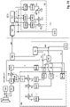
- the procedure is based on 1 explained.
- an ultrasonic burst is first generated and emitted into a free space, typically in the area surrounding the vehicle (step ⁇ of 1 ).
- An ultrasonic burst consists of several successive sound pulses with ultrasonic frequency. This ultrasonic burst is caused by a mechanical oscillator in an ultrasonic transmitter or ultrasonic transducer slowly oscillating and oscillating again.
- the ultrasonic burst thus emitted by the exemplary ultrasonic transducer is then reflected on objects in the vicinity of the vehicle and received by an ultrasonic receiver or the ultrasonic transducer itself as an ultrasonic signal and converted into an electrical reception signal (step ⁇ of 1 ).
- the ultrasound transmitter is particularly preferably identical to the ultrasound receiver and is then referred to below as a transducer.
- the proposed ultrasonic sensor contains a signal processing unit, which now analyzes and compresses the received electrical signal (step ⁇ of 1 ) for the necessary data transfer to minimize and to create free space for said status messages and other control commands from the control unit to the signal processing unit or the ultrasonic sensor system.
- the compressed electrical reception signal is then transmitted to the computer system (step ⁇ of 1 ).
- the method according to the variant described above and the advantageous configurations explained below is thus used to transmit sensor data, in particular an ultrasonic sensor, from a sensor to a computer system, in particular in a vehicle. It begins by emitting an ultrasonic burst (step ⁇ of 1 ). An ultrasonic signal is received and an electrical reception signal is formed (step ⁇ of 1 ) and carrying out a data compression of the received signal (step ⁇ of 1 ) to generate compressed data (step ⁇ of 1 ) and the detection of at least two or three or more predetermined properties.
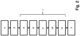
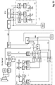
- the electrical reception signal is preferably obtained by sampling (step ya of 2 ) into a sampled received signal consisting of a time-discrete stream of samples.
- Each sample can typically be assigned a sampling time as a time stamp of this sample.
- the compression can be carried out, for example, by a wavelet transformation (step yb of 2 ) take place.
- the received ultrasonic signal in the form of the sampled reception signal can be compared with predetermined signal basic forms, which are stored in a library, for example, by forming a correlation integral (for the definition of this term, e.g. in Wikipedia) between the predetermined signal basic forms and the sampled reception signal.
- the predetermined signal basic forms are also referred to below as signal object classes.
- spectral values themselves represent a stream of time-discrete instantaneous spectral values, with each spectral value being able to be assigned a time stamp.
- An alternative but mathematically equivalent method is to use Optimal filters (English matched filter) for each predetermined signal object class (signal basic form). Since, as a rule, several prototypical signal object classes are used, which can also be subjected to different time spreads, this typically results in a time-discrete stream of multidimensional vectors of spectral values of different prototypical signal object classes and their different respective time spreads, with each of these multidimensional vectors again having a timestamp is assigned. Each of these multidimensional vectors is a so-called feature vector. It is therefore a time-discrete stream of feature vectors. A time stamp is preferably assigned to each of these feature vectors (step yb of the 2 ).
- the feature vector of the spectral values can also be supplemented by values from the past or by values that depend on them, for example time integrals or derivatives or filter values from one or more of these values, etc. This can further increase the dimension of these feature vectors within the feature vector data stream.
- the limitation to a few prototypical signal object classes during the extraction of the feature vectors from the scanned input signal of the ultrasonic sensor makes sense.
- optimal filters English matched filter
- a prototypical signal object class usually consists of a specified spectral coefficient vector, ie a specified prototypical feature vector value.
- the absolute value of a Distance of these properties the elements of the vector of the instantaneous spectral coefficients (feature vector), to at least one prototypical combination of these properties (prototype) in the form of a prototypical signal object class, which is defined by a given prototypical feature vector (prototype or prototype vector) from a library of predetermined prototypical signal object class vectors is symbolized (step yd of 2 ).
- the spectral coefficients of the feature vector are preferably normalized before correlation with the prototypes (step yc of 2 ).
- the distance determined in this distance determination can consist, for example, of the sum of all differences between a spectral coefficient of the specified prototypical feature vector (prototype or prototype vector) of the respective prototype and the corresponding normalized spectral coefficient of the current feature vector of the ultrasonic echo signal.
- a Euclidean distance would be formed by the square root of the sum of the squares of all differences between each spectral coefficient of the given prototypical feature vector (prototypes or prototype vector) of the prototype and the corresponding normalized spectral coefficient of the current feature vector of the ultrasonic echo signal.
- this spacing formation is generally too complex. Other methods of spacing are conceivable.
- a symbol and possibly also a parameter, for example the distance value and/or the amplitude before normalization, can then be assigned to each predefined prototypical feature vector (prototype or prototype vector). If the distance determined in this way falls below a first threshold value and if it is the smallest distance between the current feature vector value and one of the predefined prototypical feature vector values (prototypes or values of the prototype vectors), then its symbol is used as a recognized prototype. This results in a pairing of recognized prototypes and time stamp of the current feature vector.
- the data is then preferably transmitted (step ⁇ of 2 ), here the determined symbol that best symbolizes the recognized prototype and, for example, the distance and the time of occurrence (time stamp) to the computer system only if the amount of this distance is below the first threshold value and the recognized prototype is a prototype to be transmitted. It can be the case that prototypes that cannot be recognized, for example for noise, for example the absence of reflections, etc., are also stored. This data is irrelevant for obstacle detection and should therefore not be transmitted. A prototype is therefore recognized when the amount of the determined distance between the current feature vector value and the specified prototypical feature vector value (prototype or value of the prototype vector) is below this first threshold value (step ye der 2 ).
- an estimated value - for example, the inverse distance between the representative of the prototypical signal object class in the form of the specified prototypical feature vector (prototype or prototype vector) - and the subsequent transmission of the compressed data to the computer system if the absolute value of this estimated value (eg inverse distance) is above a second threshold value or the inverse estimated value is below a first threshold value.
- the signal processing unit of the ultrasonic sensor thus performs data compression of the received signal to generate compressed data.
- This determination of distance is also known as classification from the signal processing of statistical signals.
- classifiers are logistic regression, the cuboid classifier, the distance classifier, the nearest neighbor classifier, the polynomial classifier, the cluster method, artificial neural networks, and latent class analysis.
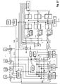
- a classifier example is in 7 shown schematically.
- a physical interface 101 controls an ultrasonic transducer 100, for example, and causes it to emit an ultrasonic transmit pulse or ultrasonic transmit burst, for example.
- the ultrasonic transducer 100 receives the from a not in 7
- the ultrasonic transmission pulse or ultrasonic transmission burst reflected by the obstacle object drawn in has an amplitude change, a delay and typically a distortion which is caused by the nature of the reflecting obstacle object.
- the ultrasonic transducer 100 converts the received reflected ultrasonic wave into an ultrasonic transducer signal 102 .
- the physical interface converts this ultrasonic transducer signal into an ultrasonic echo signal 1, typically by filtering and/or amplification.
- the feature vector extractor 111 extracts signal curve characteristics (features) from this ultrasonic echo signal 1 .
- the physical interface 101 preferably transmits the ultrasonic echo signal 1 to the feature vector extractor 111 as a time-discrete received signal consisting of a sequence of sample values. In this case, a time date (time stamp) is preferably assigned to each sampled value.
- the feature vector extractor 111 has in the example of 7 a plurality of m (where m is a positive integer) matched filters (matched filter 1 to matched filter m).
- m intermediate parameter signals 123 each relating to the presence of one of the respective intermediate parameter signals preferably assigned signal base object, preferably with the aid of a suitable filter (e.g. an optimal filter) from the sequence of sample values of the ultrasonic echo signal 1.
- the resulting intermediate parameter signals 123 are also designed as a time-discrete sequence of respective intermediate parameter signal values, each of which preferably has a date (time stamp ) are correlated. Precisely one time date (time stamp) is thus preferably assigned to each intermediate parameter signal value.
- a subsequent significance increaser 125 carries out a matrix multiplication of the vector of the intermediate parameter signal values of the intermediate parameter signal 123 with a so-called LDA matrix 126 . This is typically determined at the time of construction using methods of statistical signal processing and pattern recognition.
- the significance enhancer generates the feature vector signal 138 in this way. In doing so, it maps the m intermediate parameter signal values to n (where n is an integer) parameter signal values of the feature vector signal 138 .
- the feature vector signal thus typically comprises 138 of n parameter signals. n ⁇ m is preferred.
- feature vector is also often referred to as feature vector in statistical signal theory and in pattern recognition (also referred to below as feature vector).
- the feature vector signal 138 is thus designed, among other things, as a time-discrete sequence of feature vector signal values, each with n parameter signal values of the preferably n parameter signals of the feature vector signal 138, which the parameter signal values and further parameter signal values each have the same time date (time stamp) comprised.
- n is the dimension of the individual feature vector signal values, which are preferably equal from one feature vector value to the next feature vector value.
- a feature vector signal value is a vector with a time stamp that includes a plurality of, preferably n, parameter signal values. This respective time data (time stamp) is assigned to each feature vector signal value formed in this way.
- the evaluation of the time profile of the feature vector signal 138 in the resulting n-dimensional phase space and the closing now follows to a detected signal base object while determining an evaluation value (eg the distance).
- a distance determiner (or classifier) 112 compares the current feature vector signal value of the feature vector signal 138 with a plurality of prototype feature vector signal value prototypes previously stored in a prototype database 115 . This is explained in more detail below.
- the distance determiner (or classifier) 112 determines an evaluation value for each of the examined feature vector signal value prototypes in the prototype database 115, which indicates the extent to which the respective feature vector signal value prototype in the prototype database 115 resembles the current feature vector signal value . This evaluation value is hereinafter referred to as distance.
- the feature vector signal value prototypes are preferably each assigned to exactly one signal basic object.
- the feature vector signal value prototype of the prototype database 115 with the smallest distance to the current feature vector signal value then most closely resembles it. If the distance is less than a specified threshold value, this feature vector signal value prototype in the prototype database 115 represents the signal base object 121 recognized with the highest probability.
- This recognition process is carried out several times in succession, so that a determined signal basic object sequence results from the chronological sequence of the recognized signal basic objects 121 .
- the probable signal object 122 that is present is then determined by determining that sequence of predetermined signal basic object sequences in a signal object database 116 that is most similar to the determined signal basic object sequence.
- a signal object consists of a chronological sequence of basic signal objects.
- a symbol in the signal object database 116 is typically assigned to the signal object in a predefined manner.
- this estimation of the signal basic object sequence can be performed by a Viterbi estimator 113 .
- the Viterbi estimator determines an evaluation value for each of the predefined signal objects in the signal object database 116, the signal objects in the signal object database 116 consisting of predefined sequences of expected basic signal objects and being correlated with a respective symbol.
- the feature vector signal 138 therefore has a time profile.
- An evaluation value eg a distance
- This evaluation value which is again assigned a date (time stamp), is then preferably compared within the Viterbi estimator 113 with a threshold value vector, forming a Boolean result that can have a first and a second value.
- this Boolean result has the first value for this date (time stamp) in time
- the symbol of the signal object and the date (time stamp) assigned to this symbol are transmitted from the sensor to the computer system.
- the recognized signal object 122 is preferably transmitted with its parameters. Possibly further parameters can be transmitted depending on the detected signal object.
- the ultrasonic echo signal 1 is preferably a sequence of quantization vectors—the ultrasonic echo signal values—whose components, the measured parameters, will generally not be completely independent of one another.
- each ultrasonic echo signal value of an ultrasonic echo signal 1 by itself has insufficient selectivity for the precise determination of a signal object in complex contexts. This is precisely the deficiency in the prior art.
- the multidimensional ultrasonic echo signal value data stream is produced in the form of the ultrasonic echo signal 1.
- the multidimensional ultrasonic echo signal 1 obtained in this way in the form of one or more streams of quantization vectors is first divided into individual frames of a defined length, filtered, normalized, then orthogonalized and, if necessary, by a non-linear mapping - e.g. logarithmic processing and cepstrum analysis - suitably distorted.
- a non-linear mapping e.g. logarithmic processing and cepstrum analysis - suitably distorted.
- a significance increase of the determined intermediate parameter signal 123 takes place in a significance increase unit 125 for the actual feature vector signal 138 .
- this can be done, for example, by multiplying the multidimensional quantification sector by a so-called predetermined LDA matrix 126 .
- the components of the newly transformed feature vectors obtained in this way are not selected according to real physical or other parameters, but according to maximum significance, which results in said maximum selectivity.
- the LDA matrix 126 is previously calculated offline at the time of construction on the basis of example data streams with known signal object data sets, ie data sets that were obtained with predetermined structures of the signal curve, beforehand by means of a training step.
- the prototypes from sample data streams for the specified prototypical signal curves (prototypical signal basic objects) in the coordinates of the new parameter space are calculated in the construction phase and stored in a prototype database 115 for later recognition.
- this can also contain instructions for a computer system as to what happens in the event of successful or failed recognition of the respective signal basic object prototype is to take place.
- the computer system will be the computer system of the sensor system.
- the feature vector signal values of the feature vector signal 138 which are output by the feature extractor 111 for these prototypical signal curves of the specified signal basic objects of the ultrasonic echo signal 1 in the laboratory, are therefore saved in this prototype database 115 as signal basic object prototypes.
- dummy prototypes are generally also stored in the prototype database 115 of the basic signal object prototypes, which should largely cover all parasitic parameter combinations occurring during operation. Said basic signal object prototypes are stored in the prototype database 115.
- the distance can correspond to that in the distance finder 112 applied methods for each pairing from two different signal basic object prototypes of the prototype database 115 are determined. This then results in a minimum prototype distance. This is stored in the prototype database 115 or in the distance determiner 112, preferably also halved as half the minimum prototype distance.
- this signal basic object prototype is evaluated as recognized. From this point in time it can be ruled out that further distances to other basic signal object prototypes of the prototype database 115 calculated in the course of a continued search can supply even smaller distances. The search can then be aborted, which halves the time on average and thus saves the resources of the sensor.
- dim_cnt stands for the dimension index, which runs through up to the maximum dimension of the feature vector 138 dim.
- FV dim_cnt represents the parameter value of the feature vector signal value of feature vector 138 corresponding to index dim_cnt.
- Cb_cnt stands for the number of the signal basic object prototype in the prototype database 115.
- dim_cnt accordingly stands for the dim_cnt corresponding parameter value of the entry of the signal basic object prototype in the prototype database 115, which is assigned to the signal basic object prototype corresponding to Cb_cnt.
- Dist FV_CbE stands for the minimum Euclidean distance obtained, which is exemplary here. When searching for the smallest Euclidean distance, the number Cb_cnt that produces the smallest distance is noted.
- the degree of confidence for correct recognition is derived from the scatter of the basic data streams taken as a basis for a signal basic object prototype and the distance of the current feature vector value of the feature vector signal 138 from its center of gravity.
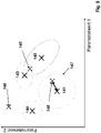
- each feature vector signal value includes a first parameter value and a second parameter value. This is only used here to better illustrate the methodology on a two-dimensional piece of paper. In reality, the feature vector signal values of the feature vector signal 138 are typically always multidimensional.
- Focal points of various prototypes 141,142,143,144 are drawn in. As described above, half the minimum distance between these basic signal object prototypes can now be stored in the prototype database 115 in the prototype database 115 . This would then be a global parameter that would be equally valid for all signal primitive prototypes in the prototype database 115 . This decision is made using this minimum distance. However, it presupposes that the scattering of the signal basic object prototypes, which are marked by their centers of gravity 141, 142, 143, 144, are more or less identical. If the distance determination (or other evaluation) by the distance determiner 112 (or classifier) is optimal, then this is also the case. This would correspond to a circle around the center of gravity 141,142,142,144 of each of the signal basic object prototypes in the prototype database 115.
- a further improvement in the recognition performance can be achieved if the spread for the signal basic object prototype in the prototype database 115 is modeled by an ellipse.
- the main axis diameter of the scattering ellipse and its tilting relative to the coordinate system in the prototype database 115 for preferably each of the basic signal object prototypes in the prototype database 115 must be stored.
- the disadvantage is another massive increase in computing power and memory requirements.
- the position of the by the distance detector 112 in the exemplary two-dimensional parameter space 8 determined current feature vector signal values of the feature vector signal 138 can now be extremely different. It is thus conceivable that a first such feature vector signal value 146 is too far away from the center of gravity coordinates 141 , 142 , 143 , 144 of the center of gravity of any basic signal object prototype in the prototype database 115 .
- This distance threshold value can be, for example, the said minimum half prototype distance. It can also be the case that the scattering ranges of the signal basic object prototypes overlap around their respective focal points 143, 142 and, for example, a second determined current feature vector signal value 145 of the feature vector signal 138 lies in the overlapping range.
- a hypothesis list can contain both signal primitive prototypes with different probabilities as an attached parameter (for different distances). It is then not a basic signal object that is passed to the Viterbi estimator 113 as the most probable one, but rather a vector of possible basic signal objects that are present to the Viterbi estimator 113 passed. From the chronological sequence of these hypothesis lists, the Viterbi estimator then searches for the possible sequence that has the greatest probability of one of the predetermined signal basic object sequences in its signal object database compared to all possible paths through the signal basic objects 121 recognized as possible by the distance detector 112 by the Viterbi estimator 113 has received hypothesis lists. In such a path, exactly one recognized signal basic object prototype of this hypothesis list must be run through this path for each hypothesis list.
- the current feature vector signal value 148 is in the scatter range (threshold ellipsoid) 147 around the center of gravity 141 of a single signal basic object prototype 141, which is thus reliably recognized by the distance detector 112 and passed on to the Viterbi estimator 113 as a recognized signal basic object 121.
- the number of assembler instructions that must be executed to compute a vector component is approximately 8 steps.
- the smallest distance between two signal basic object prototypes in the prototype database 115 is precalculated and stored in the prototype database 115 or in the distance detector 112.
- the mean search time for the distance finder 112 is thus halved.
- Further optimizations can be undertaken if the prototype database 115 is sorted according to the statistical occurrence of the signal basic object prototypes in real ultrasonic echo signals 1 . In this way it can be ensured that the most frequent signal basic object prototypes are found much faster, which further shortens the computing time of the distance determiner or classifier 112 and further reduces the power consumption.
- a _ cb cb _ no *
- a _ distance + 4 cb _ no * FV _ dimensions * 8th + 10 + 4
- the two additional assembler commands are necessary to check whether the determined distance between the current feature vector signal value and the currently examined signal basic object prototype of the prototype database 115 is below half the smallest distance between the signal basic object prototypes of the prototype database 115.
- the number CB_Anz of signal basic object prototype entries in the prototype database 115 for mobile and energy self-sufficient applications is limited to 4000 prototype database entries of signal basic object prototypes in the prototype database 115 or even less.
- the number of feature vector signal values per second within feature vector signal 138 is reduced by filtering in feature vector extractor 111 and lowering the sampling rate in feature vector extractor 111 .
- Said distance finder or classifier 112 which executes an average HMM detection method, is now used with a prototype database 115 with just under a tenth of the entries, e.g. with 4000 entries CbE and furthermore with 24 feature vector signal dimensions (i.e. 24 parameter signals) operated.
- the search is terminated when the distance of the current feature vector signal value to the processed signal basic object prototype of the prototype database 115 is below half the smallest prototype database entry distance, the effort is at least halved with suitable sorting of the prototype database 115.
- the search area can be restricted by pre-selection.
- the need to reduce the size of the prototype database 115 has advantages and disadvantages: A reduction in the number of entries in the prototype database 115 increases both the false acceptance rate FAR, i.e. the wrong signal basic object prototypes that are accepted as signal basic object prototypes, and the false rejection rate FRR, i.e. the signal basic object prototypes that are actually present that are not recognized.
- FAR false acceptance rate
- FRR false rejection rate
- the previous history i.e. the previously recognized signal basic object prototypes
- the distance determiner 112 can be used by the distance determiner 112 when forming hypotheses.
- a suitable model for this is the so-called Hidden Markov Model HMM.
- a confidence level and a distance from the measured current feature vector signal value of the feature vector signal 138 can thus be derived for each signal basic object prototype, which can also be further processed by the Viterbi estimator 113 . It also makes sense to output a list of hypotheses for each of the detected basic signal object prototypes 121, which list contains, for example, the ten most probable basic signal object prototypes with the respective probability and reliability of the detection.
- Viterbi estimator 113 Since not every temporal and spatial signal basic object sequence can be assigned to a signal object, it is possible to use a Viterbi estimator 113 to evaluate the chronological succession of the hypothesis lists of the subsequent frames.
- the signal basic object prototype sequence path through the consecutive hypothesis lists that has the highest probability and is present in the signal object database 116 of the Viterbi estimator 113 is to be found.
- such a prototype can be entered into a signal object database 116 using a learning program in the form of an entry consisting of a predetermined sequence of signal basic object prototypes; allows a keyboard.
- the most probable of the predefined sequences of signal basic object prototypes for a sequence of recognized signal basic object prototypes 121 can be determined from the sequence of the hypothesis lists of the distance determiner or the classifier 112. This also applies in particular if individual signal basic object prototypes were incorrectly recognized by the distance detector or the classifier 112 due to measurement errors. In this respect, it is very useful for the Viterbi estimator 113 to take over sequences of signal basic object prototype hypothesis lists from the distance determiner or classifier 112, as described above. The result is the signal object 122 recognized as the most probable or, analogously to the previously described emission calculation of the distance estimator or classifier 112, a signal object hypothesis list.
- Viterbi estimator 113 search accesses the signal object database 116 .
- the signal object database 116 is fed on the one hand by a learning tool and on the other hand by a tool in which these sequences of signal basic object prototypes can be defined by textual input. The possibility of a download in production is only mentioned here for the sake of completeness.
- the basis of the sequence recognition for the time sequence of the signal basic object prototypes in the Viterbi estimator 119 is a hidden Markov model, for example.
- the model is made up of different states. in the in 9 given example, these states are symbolized by numbered circles. In the example in question 9 the circles are numbered from Z1 to Z6. In between the states have transitions. These transitions are in the 9 denoted by the letter a and two indices i, j.
- the first index i designates the number of the source node, the second index j the number of the destination node.
- there are also transitions a ii or a jj which lead back to the start node.
- a probability of actually observing a k-th observable b k results from the sequence. This results in sequences of observables that can be observed with probabilities bk that can be calculated in advance.
- Every Hidden Markov Model consists of unobservable states q i .
- the transition probability aij exists between two states q i and q j .
- n stands for a discrete point in time. The transition thus takes place between step n with state q i and step n+1 with state q j .
- the emission distribution b i (Ge) depends on the state q i . As already explained, this is the probability of observing the elementary gesture Ge (the observable) when the system (Hidden Markov Model) is in state q i : p ge
- the initial states must be defined. This is done by a probability vector ⁇ i . Then it can be stated that a state q i with probability ⁇ i is an initial state: p q i 1 ⁇ ⁇ i
- a new model must be created for each sequence of signal primitive object prototypes.
- the observation probability for a temporal observation sequence of signal basic object prototypes G e ⁇ ge 1 , ge 2 , ... ge N to be determined.
- the probability p, dependent on the model M, the temporal sequence of states Q and the temporal observation sequence Ge, of observing this sequence of states Q is: p G e ⁇
- Q ⁇ , M p ge 1 , ge 2 , ... ge N
- q 1 , q 2 , ... .. q N p ge 1
- the probability of detecting a signal object is equal to a sequence of basic signal object prototypes (see also 10 ): p G e ⁇
- M j ⁇ Alles Q k p G e ⁇
- the most probable signal object model (signal object) for the observed emission Ge is determined by this summation of the individual probabilities over all possible paths Q k that lead to this observed sequence of signal basic object prototypes Ge.
- M j ⁇ Alles Q k p G e ⁇
- the calculation is carried out by recursive calculation.
- the probability of this path is a mathematical product. Therefore, a logarithmic calculation reduces the problem to a pure summation problem.
- the probability of detecting a signal object which corresponds to the detection of a model M j , corresponds to the determination of the most probable signal object model for the observed emission X. This is now carried out exclusively via the best possible path Q best p G e ⁇
- prototype database 115 contains only signal primitive prototypes.
- the detected signal objects are transmitted with the detected parameters instead of the samples. This leads to a compression of the data without leaving the signal character.
- the ultrasonic sensor then transmits the data compressed in this way, preferably only the codes (symbols) of the prototypes recognized in this way, their amplitude and/or time extension and the time of occurrence (time stamp), to the computer system.
- this prioritization does not relate to the prioritization relative to other bus users.
- the data connection between the sensor and the computer system of the vehicle is usually a point-to-point connection. Rather, the prioritization is to be understood here in terms of which datum of the data ascertained by the sensor system must be transmitted as the first control unit in terms of time.
- Reports of safety-critical errors from the sensor to the computer system have the highest priority, since they are highly likely to affect the validity of the measurement data from the ultrasonic sensor.
- This data is sent from the sensor to the computer system.
- Requests from the computer system to carry out safety-related self-tests have the second highest priority. Such commands are sent from the computer system to the sensor.
- the third-highest priority is the data from the ultrasonic sensor itself, since the latency must not be increased. All other data has lower priority for transmission over the data bus.
- the method for transmitting sensor data in particular from an ultrasonic sensor, from a sensor to a computer system, in particular in a vehicle, comprising the transmission of an ultrasonic burst with a beginning 57 and end 56 of the transmission of the ultrasonic burst and comprising receiving an ultrasonic signal and forming a received signal for a receiving time T E at least from the end 56 of the Transmission of the ultrasonic burst and including the transmission of the compressed data via a data bus, in particular a single-wire data bus, to the computer system is designed in such a way that the transmission 54 of the data from the sensor to the computer system is started with a start command 53 from the computer system to the ultrasonic sensor via the Data bus and before the end 56 of the transmission of the ultrasonic burst begins or after a start command 53 from the computer system to the sensor via the data bus and before the beginning 57 of the transmission of the ultrasonic burst begins.
- the transmission 54 then takes place periodically after the start command 53 until the end of the data
- a further variant of the proposed method thus provides for the formation of a feature vector signal (stream of feature vectors with n feature vector values and n as the dimension of the feature vector) from the received signal as the first step in data compression.
- a feature vector signal can include multiple analog and digital data signals. It therefore represents a chronological sequence of more or less complex data/signal structures. In the simplest case, it can be understood as a vectorial signal consisting of several partial signals.
- An envelope signal of the received signal (ultrasonic echo signal) can also be formed, which can then be a partial signal within the feature vector signal 138 .
- the signal can be used as an emitted ultrasonic signal, which was used to control the driver for the transmitter, or on the other hand, for example, a signal that was measured at the transmitter and thus corresponds better to the sound wave actually emitted can be used.
- a matched filter is a filter that optimizes the signal-to-noise ratio (SNR).
- SNR signal-to-noise ratio
- the predefined signal objects are to be recognized in the disturbed ultrasound reception signal.
- correlation filter, signal-matched filter (SAF) or just matched filter are also frequently found in the literature.
- the matched filter is used to optimally determine the presence (detection) of the amplitude and/or location of a known waveform, i.e. the predetermined signal object, in the presence of noise (parameter estimation). This interference can be, for example, signals from other ultrasonic transmitters and/or ground echoes.
- the optimal filter output signals are then preferably partial signals within the feature vector signal.
- Certain events can be signaled in separate partial signals of the feature vector signal. These events are signal primitives within the meaning of this invention. Signal basic objects therefore do not include signal shapes, such as square pulses or wavelets or wave trains, but prominent points in the course of the received signal and/or in the course of signals derived from it, such as an envelope signal (ultrasonic echo signal), which, for example, by filtering can be obtained from the received signal.
- an envelope signal ultrasonic echo signal
- Another signal which can be a partial signal of the feature vector signal, can signal, for example, whether the envelope of the received signal, the Ultrasonic echo signal crosses a predetermined third threshold. It is therefore a signal that signals the presence of a signal basic object within the received signal and thus the feature vector signal.
- Another signal which can be a partial signal of the feature vector signal, can signal, for example, whether the envelope of the received signal, the ultrasonic echo signal, crosses a predetermined fourth threshold value, which can be identical to the third threshold value, in an ascending manner. It is therefore a signal that signals the presence of a signal basic object within the received signal and thus the feature vector signal.
- Another signal which can be a partial signal of the feature vector signal, can signal, for example, whether the envelope of the received signal, the ultrasonic echo signal, falls below a predetermined fifth threshold value, which can be identical to the third or fourth threshold value crosses. It is therefore a signal that signals the presence of a signal basic object within the received signal and thus the feature vector signal.
- Another signal which can be a partial signal of the feature vector signal, can signal, for example, whether the envelope of the received signal, the ultrasonic echo signal, has a maximum above a sixth threshold value that is identical to the aforementioned third to fifth threshold values can, has. It is therefore a signal that signals the presence of a signal basic object within the received signal and thus the feature vector signal.
- Another signal which can be a partial signal of the feature vector signal, can signal, for example, whether the envelope of the received signal, the ultrasonic echo signal, has a minimum above a seventh threshold value, which is identical to the aforementioned third to sixth threshold values can, has. It is therefore a signal that signals the presence of a signal basic object within the received signal and thus the feature vector signal.
- the at least one preceding maximum of the ultrasonic echo signal is at a minimum distance from the minimum in order to avoid detection of noise.
- Other filters are conceivable at this point.
- It can also be checked whether the time interval between this minimum and a preceding maximum is greater than a first minimum time interval. The fulfillment of these conditions sets a flag or signal, which itself is preferably a partial signal of the feature vector signal.
- the feature vector signal can also be transformed into a significant feature vector signal, e.g. by a linear mapping or a matrix polynomial of a higher order, in a significance increase stage. In practice, however, it has been shown that this is not yet necessary, at least for today's requirements.
- signal objects are recognized and classified into recognized signal object classes within the received signal on the basis of the feature vector signal or the significant feature vector signal.
- the signal object for which the optimal filter is designed to detect can be considered recognized.
- other parameters are preferably also taken into account. For example, an ultrasonic burst was sent with increasing frequency during the burst (called chirp-up), an echo is also expected that has this modulation property.
- the signal form of the ultrasonic echo signal for example a triangular signal form of the ultrasonic echo signal
- the system can then differentiate between intrinsic echoes and extraneous echoes, as a result of which one and the same signal form is assigned to two different signal objects, namely intrinsic echoes and extraneous echoes.
- the transmission of the intrinsic echoes via the data bus from the sensor to the computer system preferably takes place with priority over the transmission of the external echoes, since the former are generally relevant to safety and the latter are generally not relevant to safety.
- At least one signal object parameter is assigned to each recognized signal object or is determined for this signal object.
- This is preferably a time stamp that indicates when the signal object was received.
- the time stamp can relate, for example, to the time at which the signal object begins in the received signal or the time it ends or the time position of the time focus of the signal object, etc.
- Other signal object parameters such as amplitude, aspect ratio, etc. are also conceivable.
- at least one of the assigned signal object parameters is thus transmitted together with a symbol for the at least one recognized signal object class.
- the signal object parameter is preferably a time value as a time stamp and specifies a time position that is suitable for being able to deduce the (receipt) time since the transmission of a previous ultrasonic burst.
- a determined distance of an object is preferably determined from this later as a function of a time value determined and transmitted in this way.
- the prioritized transmission of the recognized signal object classes follows in the form of associated symbols with time stamps, preferably together with the associated signal object parameters.
- the transfer can also in more complex data structures (records). For example, it is conceivable to first transmit the times of the recognized safety-relevant signal objects (eg identified obstacles) and then the recognized signal object classes of the safety-relevant signal objects. This further reduces the latency.
- the method according to the invention comprises at least one variant of determining a chirp value as an associated signal object parameter which indicates whether the detected signal object is an echo of an ultrasonic transmission burst with a chirp up or a chirp down or a no-chirp property.
- Chirp-up means that the frequency of the received signal increases within the signal object.
- Chirp down means that the frequency of the received signal falls within the signal object.
- No-chirp means that the frequency of the received signal remains essentially the same within the signal object.
- a confidence signal is thus also generated by forming the correlation, e.g. by forming a time-continuous or time-discrete correlation integral, between the received signal or instead of the received signal with a signal derived from the received signal on the one hand and a reference signal, for example the ultrasonic transmission signal or another expected wavelet, on the other hand.
- the confidence signal is then typically a partial signal of the feature vector signal, that is to say a component of the feature vector which consists of a sequence of vector sampling values (feature vector values).
- a phase signal is also formed on this basis, which indicates the phase shift, for example of the received signal or a signal formed therefrom (e.g. the confidence signal) compared to a reference signal, for example the ultrasonic transmission signal and/or another reference signal.
- the phase signal is then typically also a partial signal of the feature vector signal, ie a component of the feature vector, which consists of a sequence of vector samples.
- a phase confidence signal can be formed by forming the correlation between the phase signal or a signal derived therefrom and a reference signal and used as a partial signal of the feature vector signal.
- the phase confidence signal is then typically also a partial signal of the feature vector signal, that is to say a component of the feature vector, which consists of a sequence of vector samples.
- phase confidence signal When evaluating the feature vector signal, it can then be useful to compare the phase confidence signal with one or more threshold values to generate a discretized phase confidence signal, which itself is again a partial signal of the feature vector signal can be.
- the feature vector signal and/or the significant feature vector signal can be evaluated in such a way that one or more distance values are formed between the feature vector signal and one or more signal object prototype values for recognizable signal object classes .
- a distance value can be boolean, binary, discrete, digital or analog. All distance values are preferably combined with one another in a non-linear function.
- a received chirp-down echo in the form of a triangle can be discarded. This discarding is a non-linear process within the meaning of the invention.
- the triangle in the received signal can be different.
- this affects the amplitude of the triangle in the received signal.
- the optimum filter assigned to this triangular signal supplies a signal above a predetermined one ninth threshold.
- this signal object class can be assigned to a recognized signal object at the time it was exceeded.
- At least one signal object class is wavelets, which are estimated and thus detected by estimation devices (e.g. optimal filters) and/or estimation methods (e.g. estimation programs running in a digital signal processor).
- estimation devices e.g. optimal filters
- estimation methods e.g. estimation programs running in a digital signal processor.
- wavelet designates functions that can be used as a basis for a continuous or a discrete wavelet transformation.
- the word "wavelet” is a neologism of the French “ondelette” meaning "small wave” and translated into English partly literally (“onde” ⁇ "wave”) and partly phonetically (“-lette” ⁇ "-let”) became.
- wavelet was coined in the 1980s in geophysics (Jean Morlet, Alex Grossmann) for functions that generalize the short-time Fourier transform, but since the late 1980s it has been used exclusively in its current meaning.
- 1990s there was a veritable wavelet boom, triggered by the discovery of compact, continuous (up to any order of differentiability) and orthogonal wavelets by Ingrid Daubechies (1988) and the development of the fast wavelet transform (FWT) algorithm using MultiResolution Analysis (MRA) by Stephane Mallat and Yves Meyer (1989).
- MRA MultiResolution Analysis
- wavelets that have an integral other than 0 should also be permissible.
- the rectangular and triangular wavelets described below should be mentioned here as an example. This further interpretation of the term "wavelet” is widespread in the American language area and is therefore well known. This further interpretation should also apply here.
- wavelets with an integral of 0 are the Haar wavelet (Alfred Haar 1909), the Daubechies wavelets named after Ingrid Daubechies (around 1990), the Coiflet wavelets also constructed by her and the more theoretically significant Meyer wavelet ( Yves Meyer, around 1988).
- wavelets for spaces of any dimension usually a tensor product of a one-dimensional wavelet basis is used. Due to the fractal nature of the two-scale equation in MRA, most wavelets have complicated shapes, most are not closed-form. This is of particular importance because the feature vector signal mentioned above is multidimensional and therefore allows the use of multidimensional wavelets for signal object detection.
- a special variant of the proposed method is therefore the use of multidimensional wavelets with more than two dimensions for signal object detection.
- the use of appropriate optimal filters to detect such wavelets with more than two dimensions is proposed, to optionally supplement the feature vector signal with further partial signals suitable for recognition.
- a particularly suitable wavelet is, for example, a triangular wavelet. This is characterized by a start time, a temporally essentially linear increase in the wavelet amplitude up to a maximum of the amplitude and a temporally following the maximum of the triangular wavelet, an essentially linear decrease in the wavelet amplitude up to a end of the triangle wavelet.
- a rectangular wavelet is characterized by a starting point in time of the rectangular wavelet, which is followed by an increase in the wavelet amplitude with a first temporal steepness up to a first plateau point in time.
- the first plateau time of the rectangular wavelet is followed by a persistence of the wavelet amplitude with a second steepness of the wavelet amplitude up to a second plateau time of the rectangular wavelet.
- the second plateau point in time is followed by a fall with a third steepness over time up to the end of the rectangular wavelet.
- the amount of the second slope over time is less than 10% of the amount of the first slope over time and less than 10% of the amount of the third slope over time.
- the time shift of the relevant wavelet of the recognized signal object is used as a signal object parameter. For example, this shift can be determined by correlation. It is further proposed that when wavelets are used, the point in time at which the level of the output of an optimal filter suitable for detecting the relevant wavelet is exceeded is preferably used via a predefined tenth threshold value for this signal object or this wavelet.
- the ultrasonic echo signal (the envelope curve) of the received signal and/or a phase signal and/or a confidence signal etc. are preferably evaluated.
- Another possible signal object parameter that can be determined is a temporal compression or expansion of the relevant wavelet of the detected signal object. Likewise, an amplitude of the wavelet of the detected signal object can be determined.
- the recognition process can be assigned to the various signal objects that come into question for a section of the received signal, which score values indicate which probability is assigned to the presence of this signal object in accordance with the estimation algorithm used.
- score values can be assigned to the various signal objects that come into question for a section of the received signal, which score values indicate which probability is assigned to the presence of this signal object in accordance with the estimation algorithm used.
- Such a score value is binary in the simplest case.
- the score is preferably a complex, real or integer number. It can be the determined distance, for example.
- the data of the recognized signal object class and the assigned data such as time stamps and score values of the respective recognized signal object classes, ie the assigned signal object parameters, are preferably transmitted according to the first-in-first-out (FIFO) principle. This ensures that the data of the reflections of the closest objects are always transmitted first, so that the safety-critical case of the vehicle colliding with an obstacle is prioritized according to probability.
- FIFO first-in-first-out
- error states of the sensor can also be transmitted. This can also happen during a reception time T E , when the sensor uses self-test devices to determine that there is a defect and that the previously transmitted data could potentially be faulty. This ensures that the computer system can learn about a change in the evaluation of the measurement data at the earliest possible point in time and can discard it or treat it differently. This is of particular importance for emergency braking systems, since emergency braking is a safety-critical intervention that may only be initiated if the underlying data has a corresponding trust value.
- the transmission of the measurement data ie, for example, the date of the recognized signal object class and/or the transmission of the at least one assigned signal object parameter, is therefore postponed and therefore given a lower priority.
- the transmission would be aborted if an error occurred in the sensor. In some cases, however, it can also be the case that an error appears possible but is not definitely present. In this respect, the continuation of a transfer may be indicated in such cases.
- the Sensor errors that are critical to safety are therefore preferably transmitted with a higher priority.
- certain points in time in the course of the received signal can also be considered as a basic signal object within the meaning of the invention, which can be used for data compression and instead of samples of the received signal can be transmitted.
- This subset in the set of possible signal basic objects is referred to below as signal instants.
- the signal instants are therefore a special form of the signal basic objects within the meaning of the invention.
- a first possible signal point in time and thus a basic signal object is when the amplitude of the ultrasonic echo signal 1 crosses the amplitude of an eleventh threshold value signal SW in an increasing direction.
- a second possible signal point in time and thus a basic signal object is when the amplitude of the ultrasonic echo signal 1 crosses the amplitude of a twelfth threshold value signal SW in a descending direction.
- a third possible signal point in time and thus a signal base object is a maximum of the amplitude of the ultrasonic echo signal 1 above the amplitude of a thirteenth threshold value signal SW.
- a fourth possible signal point in time and thus a signal base object is a minimum of the amplitude of the ultrasonic echo signal 1 above the amplitude of a fourteenth threshold value signal SW.
- signal-time-type-specific threshold value signals SW may be used for these four exemplary types of signal times and for other types of signal times.
- the signal object of a triangular wavelet consists of the predefined sequence of three basic signal objects, which are recognized and replaced by a symbol and are preferably transmitted as this symbol together with the time of its occurrence, the time stamp.
- this exceeding of the said minimum level at the output of the said optimal filter is a further example of a fifth possible signal point in time and thus a further possible signal basic object.
- the resulting grouping and chronological sequence of detected basic signal objects can itself, for example by a Viterbi decoder, as a predefined, expected grouping or chronological sequence of basic signal objects recognized and can thus represent a basic signal object itself.
- a sixth possible signal point in time and thus a basic signal object is the occurrence of such a predefined grouping and/or chronological sequence of other basic signal objects.
- the symbol of this recognized summary signal object class and at least one assigned signal object parameter are preferably transmitted instead of the transmission of the individual basic signal objects, since this saves considerable data bus capacity.
- the data (symbol) of the signal object class of a signal object is transmitted, which is a predefined time sequence and/or grouping of other signal basic objects.
- at least one signal object class (symbol) of at least one of these other signal basic objects is not transmitted.
- a chronological grouping of basic signal objects is present in particular when the chronological distance between these basic signal objects does not exceed a predefined distance.
- the propagation time of the signal in the matched filter should be considered.
- the matched filter should be slower than the comparators.
- the change in the output signal of the optimum filter should therefore be in a fixed temporal relationship to the occurrence of the relevant signal times.
- a method is therefore proposed here for the transmission of sensor data, in particular an ultrasonic sensor, from a sensor to a computer system, in particular in a vehicle, which starts with the transmission of an ultrasonic burst and the reception of an ultrasonic signal and the formation of a time-discrete received signal consisting of a sequence of samples begins.
- a date time stamp
- At least two parameter signals are determined in each case relating to the presence of a basic signal object assigned to the respective parameter signal with the aid of at least one suitable filter (eg an optimal filter) from the sequence of samples of the received signal.
- the resulting parameter signals are also in the form of a time-discrete sequence of respective parameter signal values (feature vector values), which are each correlated with a date (time stamp).
- each parameter signal value feature vector value
- These parameter signals together are referred to below as the feature vector signal.
- the feature vector signal is thus in the form of a time-discrete sequence of feature vector signal values each having n parameter signal values, which consist of the parameter signal values and further parameter signal values each having the same date (time stamp).
- n is the dimensionality of the individual feature vector signal values, which are preferably the same from one feature vector value to the next feature vector value.
- This respective time data (time stamp) is assigned to each feature vector signal value formed in this way.
- a signal object consists of a chronological sequence of basic signal objects. A predefined symbol is typically assigned to the signal object. In other words, it is checked here whether the point to which the n-dimensional feature vector signal in the n-dimensional phase space points, on its way through the n-dimensional phase space in a predetermined time sequence, is at predetermined points in this n-dimensional phase space closer than a predetermined maximum distance approaches.
- the feature vector signal thus has a time profile.
- An evaluation value (eg a distance) is then calculated, which can, for example, reflect the probability of the existence of a specific sequence.
- This evaluation value which is again assigned a date (time stamp) is then compared with a threshold value vector, forming a Boolean result that can have a first and a second value. If this boolean result for this date in time (timestamp) has the first value, the symbol of the signal object and the date (time stamp) associated with this symbol are transmitted from the sensor to the computer system. If necessary, further parameters can be transmitted depending on the detected signal object.
- the reconstruction of a reconstructed ultrasonic echo signal model 610 from the detected signal objects 122 is particularly advantageous.
- This ultrasonic echo signal model 610 is generated from the summing linear superimposed signal curve models of the individual detected signal objects. It is then subtracted from the ultrasonic echo signal 1. A residual signal 660 is thereby formed.
- signal objects similar to the selected signal object recognized with a higher probability are better suppressed.
- the weaker signal objects stand out better in the residual signal 660 and can be recognized better (see also 18 ).
- a subtraction of the ultrasonic echo signal model 610 reconstructed from the detected signal objects from the ultrasonic echo signal 1 to form a residual signal 660 is therefore preferably also provided.
- the residual signal 660 formed in this way is then used again to form the feature vector signal 138 and the next signal object is recognized with the next higher probability. Since the signal object recognized first was removed from the input signal according to its weighting, it can no longer influence this recognition. Thus, this form of recognition delivers a better result.
- this detection method is usually slower. Therefore, it makes sense to carry out a first direct object recognition without subtraction while the measurement is still running and then, after recording all sampled values of an ultrasonic echo response of the surroundings of the vehicle, after the emission of an ultrasonic pulse or an ultrasonic burst, a repeated pattern recognition with subtraction of the Ultrasonic Echo Signal Model 610, which takes longer but is more accurate.
- this reducing classification of the ultrasonic echo signal 1 into signal objects using the ultrasonic echo signal model 610 is then ended, when the magnitudes of the samples of the residual signal 660 are below the magnitudes of a predetermined threshold curve.
- the data is transmitted in the vehicle via a serial, bidirectional single-wire data bus.
- the electrical return line is preferably ensured by the body of the vehicle.
- the sensor data are preferably sent to the computer system in a current-modulated manner.
- the data for controlling the sensor are preferably sent to the sensor in voltage-modulated form by the computer system. It was recognized that the use of a PSI5 data bus and/or a DSI3 data bus is particularly suitable for data transmission. Furthermore, it was recognized that it is particularly advantageous to transmit the data to the computer system at a transmission rate of> 200 kbit/s and from the computer system to the at least one sensor at a transmission rate> 10 kbit/s, preferably 20 kbit/s .
- the transmission of data from the sensor to the computer system should be modulated with a transmission current on the data bus, the current strength of which should be less than 50 mA, preferably less than 5 mA, preferably less than 2.5 mA.
- the current strength of which should be less than 50 mA, preferably less than 5 mA, preferably less than 2.5 mA.
- the proposed method for transmitting sensor data is carried out as follows: It begins by emitting an ultrasonic burst. An ultrasonic signal is then received, ie typically a reflection and the formation of a time-discrete received signal consisting of a temporal sequence of sampled values. A date (time stamp) is assigned to each sample. This typically reflects the time of sampling. On the basis of this data stream, a first parameter signal of a first property is determined with the aid of a first filter from the sequence of samples of the received signal.
- the parameter signal is preferably in the form of a time-discrete sequence of parameter signal values.
- Exactly one date is assigned to each parameter signal value.
- This date preferably corresponds to the most recent chronological date of a sample value that was used to form this respective parameter signal value.
- At least one other is preferably determined at the same time parameter signal of a property assigned to this additional parameter signal using an additional filter assigned to this additional parameter signal from the sequence of sampled values of the received signal, the additional parameter signals each being in the form of time-discrete sequences of additional parameter signal values.
- each additional parameter signal value is assigned the same time date (time stamp) as the corresponding parameter signal value.
- the first parameter signal and the further parameter signals are collectively referred to below as a feature vector signal.
- This feature vector signal (or also parameter vector signal) thus represents a time-discrete sequence of feature vector signal values, which consist of the parameter signal values and further parameter signal values each with the same chronological date (time stamp).
- time stamp a chronological date
- each feature vector signal value formed in this way can be assigned this respective time data (time stamp).
- the feature vector signal values of a date are then preferably compared quasi-continuously with a threshold vector, which is preferably a prototype vector, with formation of a Boolean result that can have a first and a second value.
- a threshold vector which is preferably a prototype vector
- Boolean result that can have a first and a second value.
- the Boolean result has a first value
- all further feature vector signal values can be checked.
- Other classifiers are also conceivable.
- a comparison with several different threshold value vectors is also possible. These threshold value vectors therefore represent the prototypes of predetermined signal forms. They come from the said library. A symbol is again preferably assigned to each threshold value vector.
- the last step in this case is the transmission of the symbol and possibly also the feature vector signal values and the time date (time stamp) assigned to the symbol or the feature vector signal value from the sensor to the computer system if the Boolean result has the first value for this chronological date (time stamp).
- a sensor system is therefore proposed, with at least one computer system that is able to carry out one of the methods presented above and with at least two sensors that are also able to carry out one of the methods presented above, so that these at least two Sensors can communicate with the computer system through signal object detection and are also able to transmit extraneous echoes in a compact form and to provide this additional information to the computer system.
- the sensor system is typically provided for the data transmission between the at least two sensors and the computer system to take place or be able to take place in accordance with the methods described above.
- one ultrasound reception signal ie at least two ultrasound reception signals, is typically compressed using one of the previously proposed methods and transmitted to the computer system.
- the at least two received ultrasound signals become reconstructed received ultrasound signals within the computer system reconstructed.
- the computer system then carries out object recognition of objects in the vicinity of the sensors with the aid of reconstructed ultrasound reception signals. In contrast to the prior art, the sensors do not carry out this object recognition.
- the computer system preferably additionally carries out an object recognition of objects in the vicinity of the sensors with the aid of the reconstructed ultrasound reception signals and additional signals from other sensors, in particular the signals from radar sensors.
- the computer system preferably creates an environment map for the sensors or a device, of which the sensors are a part, based on the detected objects.
- the proposed ultrasonic sensor system thus preferably comprises an ultrasonic transducer 100, a feature extractor 111 and with an estimator 150, 151 or classifier and a physical interface 101.
- the ultrasonic transducer 100 is preferably provided and/or set up to receive an acoustic ultrasonic wave signal and an ultrasonic transducer signal dependent thereon 102 to form.
- the feature vector extractor 111 is provided and/or set up to form a feature vector signal 138 from the ultrasonic transducer signal 102 .
- the ultrasonic sensor system is preferably set up and provided to use the estimator 151, 150 to recognize signal objects in the ultrasonic echo signal 1 and to classify them into signal object classes, with a signal object class also being able to include only one signal object.
- Each signal object 122 thus recognized and classified is preferably assigned at least one assigned signal object parameter and a symbol corresponding to the signal object class assigned to this signal object, or at least one assigned signal object parameter and a symbol for this signal object are determined for each signal object 122 thus recognized and classified. At least the symbol of a recognized signal object class 122 and at least the one associated signal object parameter of this recognized signal object class 122 are transmitted to a higher-level computer system via a data bus.
- the estimator 150 preferably has a distance determiner 112 and a prototype database 115 . Likewise, the estimator 150 preferably has a Viterbi estimator and a signal object database. Also, the estimator 151 can use a neural network model.
- the compression method described above corresponds to an associated decompression method, which is preferably used for decompressing ultrasonic reception data compressed and transmitted in this signal-object-oriented manner in the control computer after they have been received from the sensor via the data bus.
- an ultrasonic echo signal model is provided, which initially has no signal ( Figure 15a ).
- This ultrasonic echo signal model is now slowly filled in for each signal object by successive addition of the respective prototypical, parameterized signal curve of the signal objects 160 contained in the ultrasonic reception data, and the ultrasonic echo signal model 610 is approximated to the measured signal curve.
- the reconstructed received ultrasonic signal is preferably formed from the summed up signal courses of the signal courses of the prototypical signal objects recognized by the sensor on the basis of the ultrasonic echo signal model in the control computer of the sensor. echo signal) can happen.
- This reconstructed ultrasonic reception signal (reconstructed ultrasonic echo signal) can then be used much better in the control computer for more complicated processes such as sensor fusion than supposed obstacle object data, which are transmitted from the sensor to the control unit.
- Such a compressed transmission of data via the data bus between the sensor and the computer system reduces the data bus load and thus the criticality with regard to EMC requirements and also creates free data bus capacities, e.g. during the reception time for the transmission of control commands from the computer system to the sensor and for the transmission of status information and other data from the sensor to the computer system.
- the proposed prioritization ensures that security-relevant data are transmitted first so that there are no unnecessary dead times for the sensor.
- Figure 3a shows the course over time of a conventional ultrasonic echo signal 1 and its conventional evaluation in freely selected units for the coordinate system axes.
- a threshold value signal SW is carried along.
- the envelope signal (ultrasonic echo signal 1) of the ultrasonic received signal exceeds the threshold signal SW, the output 2 is set to logical 1. It is a temporal analog interface with a digital output level. The further evaluation is then taken over in the control unit of the sensor. Signaling errors or controlling the sensor is not possible via this analog interface, which corresponds to the prior art.
- Figure 3b shows the course over time of a conventional ultrasonic echo signal 1 and its conventional evaluation in freely selected units for the coordinate system axes.
- a threshold value signal SW is carried along.
- the envelope signal (ultrasonic echo signal 1) of the ultrasonic received signal exceeds the threshold value signal SW, the output 2 is now set to a level corresponding to the amplitude of the detected reflection. It is a temporal analog interface with an analog output level.
- the further evaluation is then taken over in the control unit of the sensor. A signalling of errors or control of the sensor is not possible via this analog interface, which corresponds to the state of the art.
- 3d the principle of symbolic signal transmission is explained. Instead of the signal off 3c only two types of triangle objects are transferred here as an example. Specifically, these are a first triangle object A for the chirp-up case and a second triangle object B for the chirp-down case. At the same time, the point in time and the amplitude of the triangular object are transmitted. If the signal is now reconstructed on the basis of this data, a corresponding signal is obtained 3d . The signal components that did not correspond to the triangular signals were removed from this signal. This means that unrecognized signal components are discarded and data is massively compressed.
- Figure 4e shows the conventional analog transmission of the points of intersection of the ultrasonic echo signal 1 of the ultrasonic received signal with the threshold signal SW.
- Fig. 4f shows the transmission of analyzed data after complete reception of the ultrasonic echo.
- Fig. 4g shows the transmission of compressed data, with symbols for signal basic objects being transmitted largely without compression in this example.
- Figure 5h shows the transmission of compressed data, symbols for signal basic objects being compressed into symbols for signal objects in this example.
- a first triangular object 59 is recognized and transmitted with a time sequence of exceeding a threshold value, which characterizes this, followed by a maximum and falling below a threshold value.
- a double peak with saddle point 60 above the threshold signal is detected.
- distinctive Here is the sequence of the threshold value signal SW being exceeded by the ultrasonic echo signal 1 followed by a maximum of the ultrasonic echo signal 1 followed by a minimum above the threshold value signal SW followed by a maximum above the threshold value signal SW followed by falling below the threshold value signal SW
- the symbol for this double peak with saddle point is transmitted.
- a time stamp is also transmitted.
- Other parameters of the double peak with saddle point are preferably also transmitted, such as the positions of the maxima and the minimum or a scaling factor.
- a triangular signal is then recognized again as the signal base object as the threshold value signal SW being exceeded by the ultrasonic echo signal 1, followed by a maximum of the ultrasonic echo signal 1, followed by the threshold value signal SW being undershot by the ultrasonic echo signal 1.
- a double peak is then recognized again, but the minimum of the ultrasonic echo signal 1 is now below the threshold value signal SW.
- This dual peak can therefore be treated as a separate signal object, for example, if necessary. As can easily be seen, this treatment of the signal leads to a massive data reduction.
- the position of the by the distance determination 112 in the two-dimensional parameter space in this embodiment 8 determined current feature vector signal values of the feature vector signal 138 can be very different. It is thus conceivable that such a first feature vector signal value 146 is too far away from the center of gravity coordinates 141 , 142 , 143 , 144 of the center of gravity of any basic signal object prototype in the prototype database 115 .
- This distance threshold value can, for example, be the said minimum half prototype distance among the signal basic object prototypes of the prototype database 115. It can also be the case that the scattering ranges of signal basic object prototypes in the prototype database 115 overlap around their respective focal points 143, 142 and a second determined current feature vector signal value 145 of the feature vector signal 138 lies in such an overlapping range.
- a hypothesis list can contain both signal primitive object prototypes with different probabilities because of different distances as an attached parameter. These probabilities are preferably represented by the distances.
- a (single) basic signal object is then not transferred to the Viterbi estimator 113 as the most probable, but rather a vector of basic signal objects that may be present is transferred to the Viterbi estimator 113 .
- the Viterbi estimator 113 selects the possible sequence that has the greatest probability of one of the predetermined signal basic object sequences in its signal object database compared to all possible paths through the signal basic objects 121 recognized as possible by the distance detector 112 by the Viterbi estimator 113 hypotheses lists received. In such a path, exactly one recognized signal basic object prototype of this hypothesis list must be run through this path for each hypothesis list.
- the current feature vector signal value 148 is in the scatter range (threshold ellipsoid) 147 around the center of gravity 141 of a single signal basic object prototype 141, which is thus reliably recognized by the distance detector 112 and passed on to the Viterbi estimator 113 as a recognized signal basic object 121.
- the distance determiner 112 preferably compares each resulting feature vector signal value of the feature vector signal 138 with each signal basic object prototype in the prototype database 115.
- the prototype database 115 contains an entry for each of the signal basic object prototypes in the prototype database 115 with a focus vector, e.g. 141,142,143,144 of the respective signal basic object prototype of the prototype database 115.
- a distance between the currently examined feature vector signal value of the feature vector signal 138 and the currently examined centroid vector of the prototype database 115 is calculated by the distance determiner 112.
- the distance determiner 112 can also evaluate the similarity between the focus vector, e.g.
- the distance determiner 112 determines whether a focus vector, e.g. which centroid vector e.g. 141,142,143,144 of the basic signal object prototypes in the prototype database 115 is most similar to the current feature vector signal value of the feature vector signal 138, i.e. has the smallest distance. If necessary, the distance determiner 112 determines a list of focus vectors, e.g.
- 9 12 serves to explain the HMM method used by the Viterbi estimator 113 to identify the signal object as the most probable sequence of signal basic object prototypes based on a sequence of recognized signal basic object prototypes 121 as a recognized signal object 122. the 9 is explained in the text above.
- 11 shows a preferred state sequence in the Viterbi estimator 113 for the continuous detection of one of signal objects, as is typically necessary for the detection of autonomous driving tasks. the 11 is explained in the text above.
- FIG. 1 shows an alternative embodiment with an estimator 151 implemented as a neural network model.
- the data interface, the data bus and the control unit are not shown for the sake of simplicity.
- the ultrasonic transducer 100 is controlled and measured by a physical interface 101 by means of an ultrasonic transducer signal 102 .
- the physical interface 101 is used to drive the ultrasonic transducer 100 and to process the ultrasonic transducer signal 102 received by the ultrasonic transducer 100 to form the ultrasonic echo signal 1 for the subsequent signal object classification.
- the ultrasonic echo signal 1 is preferably a digitized signal from a chronological sequence of sampled values.
- the feature vector extractor 111 again has various devices, here by way of example n optimal filters (optimal filter 1 to optimal filter n, with n being a positive integer).
- the outputs of the optimal filters form the intermediate parameter signal 123.
- integrators, filters, differentiators, logarithmic circuits and/or other signal-processing sub-devices and combinations thereof, depending on the application can also be used, which then generate the n-dimensional intermediate parameter signal 123.
- An advantageously used significance enhancer serves to map the n-dimensional space of the intermediate parameter signal 123 onto an m-dimensional space of the feature vector signal 138 .
- m is a positive integer.
- m is smaller than n.
- this serves to maximize the selectivity of the parameter values from which each feature vector signal value of the feature vector signal 138 results.
- This is preferably done by a linear mapping with the help of an offset value determined in the laboratory using statistical methods, which is added to the values of the intermediate parameter signal, and a so-called LDA matrix, with which the respective vector of the respective sampling values of the intermediate parameter signals 123 is multiplied to form the feature vector signal 138 in each case.
- the estimator 151 attempts to recognize the signal objects in the data stream of the feature vector signal values of the feature vector signal 138 with the aid of a neural network model 151 .
- the basic signal object prototypes and the signal objects are encoded via the networking of the nodes within the neural network model and its parameterization within the neural network model.
- the estimator 151 then outputs the recognized signal objects 122 .
- an ultrasonic echo signal model is generated that has no signal. ( 13a ).
- the ultrasound echo signal model is parameterized with a model parameter SA, which is correlated, for example, with the time t since the transmission of the ultrasound pulse or burst.
- This ultrasonic echo signal model is then preferably suitably parameterized by adding the first signal object 160 transmitted from the sensor to the control unit with data transmission priority 1, which describes a triangular shape with chirp-down A ( Figure 13b ).
- the second signal object 161 in triangular form with chirp-up characteristic B, transmitted with data transmission priority 2, is not taken into account here for the reconstruction of the chirp-down signal.
- the third signal object 162 in double peak form with chirp-up characteristic B, transmitted with data transmission priority 3, is not taken into account here for the reconstruction of the chirp-down signal.
- the ultrasonic echo signal model that has already been supplemented is then supplemented, suitably parameterized, preferably by adding the fourth signal object 163, which is transmitted from the sensor to the control unit with data transmission priority 4 and describes a triangular shape with chirp-down A ( 13c ).
- the ultrasonic echo signal model that has already been supplemented is then supplemented, suitably parameterized, preferably by adding the fifth signal object 164, which is transmitted from the sensor to the control unit with data transmission priority 5 and describes a triangular shape with chirp-down A ( Figure 13d ).
- the sixth signal object 165 in double-peak form with chirp-up characteristic B, transmitted with data transmission priority 6, is not taken into account here for the reconstruction of the chirp-down signal.
- the resulting reconstructed envelope signal is the reconstructed chirp-down ultrasonic echo signal.
- the ultrasonic echo signal decompressed and reconstructed in this way is then typically used for object recognition in the control unit or at another location in the vehicle.
- an ultrasonic echo signal model is generated that has no signal. ( 14a ).
- the ultrasound echo signal model is parameterized with a model parameter SA, which is correlated, for example, with the time t since the transmission of the ultrasound pulse or burst.
- the first signal object 160 in triangular form with chirp-down characteristic A, transmitted with data transmission priority 1, is not taken into account here for the reconstruction of the chirp-up signal.
- This ultrasonic echo signal model is then preferably suitably parameterized by adding the second signal object 161 transmitted from the sensor to the control unit with data transmission priority 2, which describes a triangular shape with chirp-up B ( Figure 14b ).
- This ultrasonic echo signal model is then preferably suitably parameterized by adding the third signal object 161 transmitted from the sensor to the control unit with data transmission priority 3, which describes a double peak shape with chirp-up B ( Figure 14c ).
- the fourth signal object 162 in triangular form with chirp-down characteristic A, transmitted with data transmission priority 4, is not taken into account here for the reconstruction of the chirp-up signal.
- the fifth signal object 163 in triangular form with chirp-down characteristic A, transmitted with data priority 5, is not taken into account here for the reconstruction of the chirp-up signal.
- This ultrasonic echo signal model is then preferably suitably parameterized by adding the sixth signal object 165 transmitted from the sensor to the control unit with data transmission priority 6, which describes a triangular shape with chirp-up B ( Figure 14d ).
- the resulting reconstructed envelope signal is the reconstructed chirp-up ultrasonic echo signal.
- the ultrasonic echo signal decompressed and reconstructed in this way is then typically used for object recognition in the control unit or at another location in the vehicle.
- Figs. 15 and 16 show the decompression of the transmitted envelope signal (ultrasonic echo signal 1) of the ultrasonic received signal with chirp-up signals and chirp-down signals.
- an ultrasonic echo signal model is generated that has no signal.
- the ultrasound echo signal model is parameterized with a model parameter SA, which is correlated, for example, with the time t since the transmission of the ultrasound pulse or burst.
- This ultrasonic echo signal model is then preferably suitably parameterized by adding the first signal object 160 transmitted from the sensor to the control unit with data transmission priority 1, which describes a triangular shape with chirp-down A ( Figure 15b ).
- This ultrasonic echo signal model is then preferably suitably parameterized by adding the second signal object 161 transmitted from the sensor to the control unit with data transmission priority 2, which describes a triangular shape with chirp-up B ( Figure 15c ).
- This ultrasonic echo signal model is then preferably suitably parameterized by adding the third signal object 162 transmitted from the sensor to the control unit with data transmission priority 3, which describes a double peak shape with chirp-up B ( Figure 15d ).
- This ultrasonic echo signal model is then preferably suitably parameterized by adding the fourth signal object 163 transmitted from the sensor to the control unit with data transmission priority 4, which describes a triangular shape with chirp-down A (FIG. 16d).
- This ultrasonic echo signal model is then preferably suitably parameterized by adding the fifth signal object 164 transmitted from the sensor to the control unit with data transmission priority 5, which describes a triangular shape with chirp-down A ( 16f ).
- This ultrasonic echo signal model is then preferred by adding it to the one transmitted from the sensor to the control unit with data transmission priority 6 sixth signal object 165, which describes a triangular shape with chirp-up B, suitably parameterized ( 16g ).
- the resulting reconstructed envelope signal is the reconstructed chirp-up/chirp-down ultrasonic echo signal.
- the ultrasonic echo signal decompressed and reconstructed in this way is then typically used for object recognition in the control unit or at another location in the vehicle.
- the reconstructor 600 explained in terms of its function can be used not only in the control unit, but also in the sensor itself prior to the data transmission.
- the reconstructor 600 generates a reconstructed ultrasonic echo signal model 610 as in FIGS Figs. 13 to 17 presented according to purpose. This is subtracted from the previously received ultrasonic echo signal 1 in a subtractor 602 .
- the ultrasonic echo signal 1 is preferably stored in the form of digital sampled values in a memory 601, preferably in a chronological order.
- a stored sample value corresponds to the Ultrasound echo signal 1 preferably with exactly one value of the reconstructed ultrasound echo signal model 610, which is preferably also stored in a reconstruction memory 603.
- Reconstruction memory 603 may be part of reconstructor 600 .
- This additional feedback branch 600,610,603,602,601 can also be used for other classifiers, such as for the device in FIG 12 be used.
- In 20 is a similar device as in 18 shown, although the arrangement of the blocks of 19 in 20 is changed.
- the system initially includes the data compression of sensor signal data from sensors S1, S2, Sm based on signal curve characteristics, this data compression taking place without examining or being able to examine which real obstacle objects exist on the basis of the sensor signals.
- the sensor signal data compressed in this way is transmitted via a data bus to a data processing unit in which the data is decompressed, the obstacle objects that actually exist are recognized and their changes are predicted during a number of prediction intervals.
- the results of the investigations can be signaled by means of a display, specifically either optically and/or acoustically and/or by displaying pictograms or the like symbolizing the obstacle objects identified. and/or tactile.
- FIG. 22 shows the reception and compression of the ultrasonic signals in an ultrasonic sensor with a driver DK for a US converter TR and with a receiver RX, the transmission of the compressed data via a data bus DB to a data processing unit ECU and the decompression of the compressed data in the data processing unit ECU.
- the ultrasonic transducer TR is controlled by the driver DR, which for this purpose receives control signals from the data processing unit ECU, for example.
- the receiver RX connected to the ultrasonic converter TR and to the driver DR prepares the received ultrasonic signals in such a way that a feature extraction FE connected to the receiver RX can be carried out.
- the result of the feature extraction FE is an overall feature vector signal F0, which is stored in a zeroth buffer IM0.
- This zeroth buffer IM0 transfers the total feature vector signal F1 to a zeroth adder A0, from which the total feature vector signal F1 is passed to an artificial neural signal object recognition network NN0, which is trained to recognize individual signal objects from the total feature vector signal F1.
- the ultrasonic sensor also includes a first buffer IM1 and a second buffer IM2 and more, in 1 buffers, not shown, with increasing numbering, up to an nth buffer IMn.
- n is a natural number greater than or equal to 2 and represents the number of storable, recognizable signal objects.
- the zeroth buffer IM0 to the nth buffer IMn are controlled by a recognition controller RC, which in turn is controlled by a system controller SCU.
- the first buffer IM1 stores a first recognized signal object O1.
- the second buffer IM2 stores a second recognized signal object O2.
- the nth buffer IMn stores an nth recognized signal object On.
- the first detected signal object O1 is transferred from the first buffer IM1 to a first artificial neural individual reconstruction network NN1 as an input value.
- the second recognized signal object O2 is transferred from the second buffer IM2 to a second artificial neural individual reconstruction network NN2 as an input value.
- the nth recognized signal object On is passed from the nth buffer IMn to an nth individual artificial neural reconstruction network NNn as an input value.
- the first individual neural reconstruction network NN1 reconstructs a first reconstructed individual feature vector signal R1 from the first recognized signal object O1.
- the second neural individual reconstruction network NN2 reconstructs a second reconstructed individual feature vector signal R2 from the second recognized signal object O2.
- the nth neural individual reconstruction network NNn reconstructs an nth reconstructed individual feature vector signal Rn from the nth recognized signal object On.
- the reconstructed individual feature vector signals R1,R2,...,Rn are summed to form a reconstructed overall feature vector signal RF.
- the nth reconstructed individual feature vector signal Rn is added to an (n-1)th reconstructed individual feature vector signal Rn-1 at an nth adder An.
- each ith reconstructed single feature vector signal is added at an ith summer to an (i-1)th reconstructed feature vector signal, where i is any natural number between 1 and n.
- the second reconstructed discrete feature vector signal R2 is added at a second summer A2 and the first reconstructed discrete feature vector signal R1 is added at a first summer A1.
- the result of adding all the reconstructed single feature vector signals is a reconstructed feature vector signal RF.
- the reconstructed feature vector signal RF is subtracted from the total feature vector signal F1 at the zeroth summer A0.
- the result is a feature vector residual signal F2, which is passed from the zeroth summer A0 as an input to the signal object recognition neural network NN0.
- the neural signal object recognition network NN0 recognizes the objects from the feature vector residual signal F2.
- the first detected signal object O1 is transferred to the first buffer IM1.
- the second recognized signal object O2 is transferred to the second buffer IM2 and so on until finally the nth recognized signal object On is transferred to the nth buffer IMn.
- the subtraction of the reconstructed feature vector signal RF from the total feature vector signal F1 and the subsequent object recognition and reconstruction of the total feature vector signal F1 using the neural individual reconstruction networks NN1,NN2,...,NNn is carried out until the reconstructed feature vector signal RF is identical to the total feature vector signal F1 , i.e. until the feature vector residue signal F2 equals zero. This means that the signal objects from the overall feature vector signal F1 were correctly recognized by the neural signal object recognition network NN0.
- the first detected signal object O1 is transferred from the first buffer IM1 to an ultrasonic transmitter controller TU.
- the second detected signal object O2 is transferred from the second buffer IM2 to the ultrasonic transmitter controller TU.
- the nth recognized signal object On is transferred from the nth buffer IMn to the ultrasonic transmitter controller TU.
- the ultrasonic transmitter controller TU transfers the compressed, recognized signal objects to a data bus interface TRU of the data bus DB, via which the compressed data are transmitted to a data bus interface TRE of the data processing unit ECU.
- the recognition control RC and the ultrasonic transmitter control TU are controlled by the ultrasonic system control SCU via an internal data bus IDB.
- the data bus interface TRE of the data processing unit ECU transfers the data received via the data bus DB to a controller TEC of the data processing unit ECU.
- the controller TEC of the data processing unit ECU transfers the data received via the data bus interface TRE and representing a first transmitted signal object E1 to a first buffer store EM1 and the data received via the data bus interface TRE and representing a second transmitted signal object E2 to a second buffer store EM2 the data processing unit ECU.
- the received data representing an i-th transmitted signal object are transmitted to an i-th buffer of the data processing unit ECU, i being a natural number between 2 and n.
- n is the number of storable, recognized signal objects.
- the received data representing an nth transmitted signal object En is transmitted to an nth intermediate memory EMn of the data processing unit ECU.
- the first transmitted signal object E1 is transferred from the first buffer store EM1 in the data processing unit ECU to a first neural individual decompression network ENN1 in the data processing unit ECU as an input value.
- the second transmitted signal object E2 is transferred from the second buffer store EM2 in the data processing unit ECU to a second neural individual decompression network ENN2 in the data processing unit ECU as an input value.
- the nth transmitted signal object En is transferred from the nth buffer store EMn in the data processing unit ECU to an nth neural individual decompression network ENNn in the data processing unit ECU as an input value.
- the neural individual reconstruction networks ENN1,ENN2,...,ENNn of the data processing unit ECU are parameterized in exactly the same way as the corresponding neural individual reconstruction networks NN1,NN2,...,NNn in the ultrasonic sensor.
- the first neural individual decompression network ENN1 of the data processing unit ECU is parameterized in exactly the same way as the first neural individual reconstruction network NN1 in the ultrasonic sensor.
- the second neural individual decompression network ENN2 of the data processing unit ECU is parameterized in exactly the same way as the second neural individual reconstruction network NN2.
- the i-th neural individual decompression network is ENNn of the data processing unit ECU parameterized in the same way as the i-th individual neural reconstruction network NNn in the ultrasonic sensor, where i is a natural number between 1 and n.
- the nth neural individual decompression network ENNn of the data processing unit ECU is parameterized in exactly the same way as the nth neural individual reconstruction network NNn.
- n corresponds to the number of storable, recognizable objects.
- the first neural individual decompression network ENN1 of the data processing unit ECU reconstructs a first reconstructed individual feature vector signal ER1 from the transmitted data for the first transmitted signal object E1.
- the second neural individual decompression network ENN2 of the data processing unit ECU reconstructs a second reconstructed individual feature vector signal ER2 from the transmitted data for the second transmitted signal object E2.
- the nth neural individual decompression network ENNn of the data processing unit ECU reconstructs an nth reconstructed individual feature vector signal ERn from the transmitted data for the nth transmitted signal object En.
- the first reconstructed individual feature vector signal ER1 in the data processing unit ECU and the second reconstructed individual feature vector signal ER2 in the data processing unit ECU and all further reconstructed individual feature vector signals in the data processing unit ECU up to and including the nth reconstructed individual feature vector signal ERn are summed to form a reconstructed overall feature vector signal ER in the data processing unit ECU.
- the nth reconstructed individual feature vector signal ERn is added to an (n-1)th reconstructed individual feature vector signal ERn-1 at an nth adder ESn in the data processing unit ECU.
- each i-th reconstructed individual feature vector signal is added to an i-th summer of the data processing unit ECU to form an (i-1)-th reconstructed individual feature vector signal, where i is any natural number between 1 and n.
- the second reconstructed individual feature vector signal ER2 is added at a second adder ES2 of the data processing unit ECU and that The first reconstructed individual feature vector signal ER1 is added at a first adder ES1 in the data processing unit ECU.
- the result of adding all the reconstructed individual feature vector signals is the reconstructed overall feature vector signal ER of the data processing unit ECU.
- the sensor signal coming from the receiver RX of the US sensor is stored in the buffer IM0.
- this signal object is stored in a buffer provided for this purpose and the individual feature vector R1,R2,...,Rn is generated by a neural individual reconstruction network NN1,NN2, assigned to the buffer. ..,NNn.
- the individual feature vector signal in question is then transformed back into the time domain, specifically with the aid of a so-to-speak “inverse” feature extraction IFE, which leads to a representation of the signal object in the time domain, ie to a curve.
- This curve progression is now subtracted from the sensor signal, so that a residual sensor signal is formed which, after feature extraction FE, is supplied to the signal object recognition network as a total feature vector residual signal.
- the process described above is then repeated accordingly.
- the previously described iterative process of successive individual extraction of signal objects can also be carried out in a corresponding manner for the above based on 22 described data compression process.
- an individual feature vector signal is subtracted step by step from the total feature vector signal. This can also be done by using only a single neural individual reconstruction network instead of associating a separate individual reconstruction network with each buffer.
- REK is in 23 indicated which components belong to the so-called reconstructor, which is used, for example, in 19 denoted by reference numeral 600.
- the dashed block corresponds to REK in 23 according to the reconstructor 600 19 .
- the reconstruction memory 603 corresponds to the reconstruction memory RSP 19 .
- the structure of the reconstructor REK according to 23 can also be used, for example, to carry out this process in parallel instead of a serial sequential signal object extraction or detection. This is in 25 shown.
- the neural signal object recognition network NN0 is connected to the individual buffers IM1, IM2, . . . , IMn via separate lines in each case.
- the inverse transformation of the individual feature vector signals R1,R2,Rn-1,Rn generated by the neural individual reconstruction networks NN1,NN2,...,NNn into the time domain is again carried out by separate inverse feature extractions IFE1,IFE2,IFEn-1,IFEn.
- the sum of all the inverse-transformed signal objects ie the corresponding curves
- the result can, but does not necessarily have to be, stored in a reconstruction memory RSP.
- the basis of the embodiment according to 25 shown possibility of parallel processing of the signal object extraction can be in an analogous manner in the embodiments according to Figs. 22 to 24 realize.
- the neural signal object recognition network NN0 would then be connected to the buffers IM1, IM2, . . . , IMn by separate lines.
- FIGs. 26 and 27 Based on Figs. 26 and 27 the detection of obstacle objects based on the reconstructed overall feature vector signals EF1,EF2,...,EFm of a number of sensors S1,S2,S3,...,Sm is described below, with in 27 Furthermore, in the form of a block diagram, a model part (right part of the 27 ) is shown, with which predictions about the change in the obstacle objects with regard to their relative position to a vehicle due to a relative movement of both can be specified.
- FIG. 26 shows a number of sensors S1, S2, S3,..., Sm, whose compressed sensor signal data are transmitted to a data processing unit ECU.
- This data processing unit ECU may be the same as the aforementioned data processing unit or a separate one.
- a reconstruction and thus a decompression of the sensor signal data is assigned to the transmitted compressed sensor signal data of each sensor (see SR1ER,SR2ER,SR3ER,...,SRmER).
- the input variables 27 are several, here m, reconstructed overall feature vector signals ER of the data processing unit ECU for m different sensors S1, S2, S3,..., Sm or m different sensor systems. To avoid confusion with the references ER1 to Ern 22 to be avoided are those reconstructed at different points in time Overall feature vector signals of the m sensors S1 to Sm are denoted by the reference symbols EF1, EF2 to EFm.
- the reconstructed total feature vector signals EF1,EF2 to EFm representing the signals of the various sensors S1,S2,S3,...,Sm (hereinafter referred to as total feature vector signals of a sensor) are processed to identify obstacle objects HO1,HO2,.. .,Hop to recognize.
- the model part based on the obstacle objects HO1,HO2,...,HOp detected in the real part, predictions are made about the spatial positions of the obstacle objects between the measurement times, which can be read out with a higher sampling rate.
- the problem that is to be solved is that, despite not arbitrarily short time intervals between the ultrasonic measurements between the transmission of successive ultrasonic pulses (burst), a statement is to be made about the change in the obstacle objects with regard to their position relative to the vehicle.
- the model part simulates reality, so to speak, so that the vehicle can also navigate between the ultrasonic measurements during autonomous driving, i.e. without ultrasonic pulses being emitted at specific times.
- the actual measuring rate should be selected as high as possible in order to compare the model with the real measured values after each measurement and thus keep it as close as possible to reality. This comparison takes place through the interaction between the real part and the model part.
- This in 27 The block diagram shown can preferably be implemented in a data processing unit ECU such as an ultrasonic measurement system control unit of a vehicle.
- the method in the real part runs cyclically in recognition periods EP, which are subdivided into cycles (see 28 ).
- a first reconstructed feature vector signal EV1 of the real part is subtracted at a first adder RS1.
- the term “sensor” is used in this text as a more compact form of expression. However, the person skilled in the art is aware that a sensor system can also behave like a sensor, so that the designation "sensor” always also means “sensor system”.
- the result of the subtraction is the first corrected feature vector signal EC1 as an input value for an overall obstacle detection neural network ANNO.
- the value of the first reconstructed feature vector signal EV1 is therefore set to zero, so that it does not produce any change in this phase.
- a second reconstructed feature vector signal EV2 is subtracted from the reconstructed total feature vector signal EF2 of the second sensor S2 at a second adder RS2.
- the result of the subtraction is the second corrected feature vector signal EC2 as an input value for the overall obstacle detection neural network ANNO.
- the value of the second reconstructed feature vector signal EV2 is therefore set to zero, so that it does not produce any change in this phase.
- a third reconstructed feature vector signal EV3 is subtracted from the reconstructed overall feature vector signal EF3 of the third sensor S3 at a third adder RS3.
- the result of the subtraction is the third corrected feature vector signal EC3 as an input value for the overall obstacle detection neural network ANNO. So only the result of the subtraction is passed on to the overall neural obstacle detection network ANNO, the deviates from the already existing obstacle object detection result in the form of the third reconstructed feature vector signal EV3.
- the value of the third reconstructed feature vector signal EV3 is therefore set to zero, so that it does not produce any change in this phase.
- An mth reconstructed feature vector signal EVm is subtracted from a reconstructed total feature vector signal EFm of the mth sensor Sm at an mth adder RSm.
- the result of the subtraction is the m-th corrected feature vector signal ECm as an input value for the overall obstacle detection neural network ANNO.
- the variable m represents the number of sensors.
- the overall neural obstacle detection network ANNO recognizes a most likely dominant obstacle object HO1, HO2, . . . HOp from the corrected feature vector signals EC1 to ECm.
- the first obstacle object HO1 detected by the overall obstacle detection network ANNO in the first cycle is stored in a first buffer store EO1 of the real part. This changes the first reconstructed feature vector signal EV1, which will be explained later.
- the second obstacle object HO2 detected in the second cycle by the overall obstacle detection network ANNO is stored in a second buffer EO2 of the real part.
- the second reconstructed feature vector signal EV2 changes, which will be explained later.
- the p-th obstacle object HOp recognized by the overall obstacle detection network ANNO in the p-th cycle is stored in a p-th buffer EOp of the real part.
- variable p here represents the number of detected obstacle objects and thus the number of cycles per detection period.
- a first neural individual obstacle object detection network RNN1 of the real part reconstructs from the information stored in the first buffer EO1 m feature vector signals RO11 to RO1m, which at least partially represent the first detected obstacle object HO1 (hereinafter referred to as the feature vector signal of the first detected obstacle object) and which together with other feature vector signals RO22,. ..,ROp1 serve to correct the input of the total feature vector signal EF1,EF2,...,EFm of the sensors S1,S2,...,Sm, which will be described further below.
- the first obstacle object HO1 representing m reconstructed feature vector signals RO11 to RO1m of the first obstacle object HO1 include a reconstructed feature vector signal RO11 of the first obstacle object HO1 to correct the total feature vector signal EF1 of the first sensor S1 and a reconstructed feature vector signal RO12 of the first obstacle object HO1 to correct the total feature vector signal EF2 of the second Sensor S2 and a reconstructed feature vector signal RO13 of the first obstacle object HO1 to correct the total feature vector signal EF3 of the third sensor S3, etc., up to a reconstructed feature vector signal RO1m of the first obstacle object HO1 to correct the total feature vector signal EFm of the mth sensor Sm first neural single obstacle object detection network RNN1 a reconstructed feature vector signal RO1 of the first obstacle object HO1 for all m sensors S1 to Sm.
- This reconstructed feature vector signal RO1 of the first obstacle object HO1 for all m sensors S1 to Sm represents a model idea of an obstacle object with recognized properties, such as position in space, orientation, object type, direction of movement, object speed, etc.
- This is preferably at least partially a cascade of the others reconstructed Feature vector signals RO11 to RO1m of the first obstacle object HO1 for the m sensors S1 to Sm in a common column vector.
- the reconstructed feature vector signal RO1 of the first obstacle object HO1 for all m sensors S1 to Sm is temporarily stored in a first obstacle object memory SP1 at the end of the first cycle.
- the output of the first obstacle object memory SP1 is the first reconstructed and stored feature vector signal ROS1 of the first obstacle object HO1.
- a second neural single obstacle object detection network RNN2 of the real part reconstructs from the information stored in the second buffer EO2 m feature vector signals RO21 to RO2m, which at least partially represent the second obstacle object HO2 (hereinafter referred to as the feature vector signal of the second recognized obstacle object) and which together with other feature vector signals RO21,.. .,ROp are used to correct the input of the composite feature vector signal EF1,EF2,...,EFm of the sensors S1,S2,...,Sm, as will be described later.
- the second obstacle object HO2 representing m reconstructed feature vector signals RO21 to RO2m of the second obstacle object HO2 include a reconstructed feature vector signal RO21 of the second obstacle object HO2 to correct the total feature vector signal EF1 of the first sensor S1 and a reconstructed feature vector signal RO22 of the second obstacle object HO2 to correct the total feature vector signal EF2 of the second sensor S2 and a reconstructed feature vector signal RO23 of the second obstacle object HO2 to correct the overall feature vector signal EF3 of the third sensor S3, etc., up to a reconstructed feature vector signal RO2m of the second obstacle object HO2 to correct the overall feature vector signal EFm of the mth sensor Sm second neural single obstacle object detection network RNN2 out a reconstructed feature vector signal RO2 of the second obstacle object HO2 for all m sensors S1 to Sm.
- This reconstructed feature vector signal RO2 of the second obstacle object HO2 for every m sensors S1 to Sm represents a model idea of an obstacle object with recognized properties, such as position in space, orientation, object type, direction of movement, object speed, etc.
- This is preferably at least partially a cascading of the other reconstructed feature vector signals R21 to R2m of the second obstacle object HO2 for the m sensors S1 to Sm in a common column vector.
- the reconstructed feature vector signal RO2 of the second obstacle object HO2 for all m sensors S1 to Sm is temporarily stored in a second obstacle object memory SP2 at the end of the second cycle.
- the output of the second obstacle object memory SP2 is the second reconstructed and stored feature vector signal ROS2 of the second obstacle object HO2.
- a p-th neural single obstacle object detection network RNNp of the real part reconstructs from the information stored in the p-th buffer EO2 m feature vector signals ROp1 to ROpmm due to at least partially represent the first recognized obstacle object HO1 (hereinafter referred to as the feature vector signal of the first recognized obstacle object) and together with other feature vector signals ROp1 serve to correct the input of the total feature vector signal EF1,EF2,...,EFm of the sensors S1,S2,...Sm, which will be described further below.
- the p-th single obstacle object recognition neural network RNNp outputs a reconstructed feature vector signal ROp of the p-th obstacle object HOp for all m sensors S1 to Sm.
- This reconstructed feature vector signal ROp of the pth obstacle object HOp for all m sensors S1 to Sm represents a model idea of an obstacle object with recognized properties, such as position in space, orientation, object type, direction of movement, object speed, etc.
- This is preferably at least partially a cascade the other reconstructed feature vector signals Rp1 to Rpm of the p-th obstacle object HOp for the m sensors S1 to Sm in a common column vector.
- the reconstructed feature vector signal ROp of the pth obstacle object HOp for all m sensors S1 to Sm is temporarily stored in a pth obstacle object memory SPp at the end of the pth cycle.
- the output of the p-th obstacle object store SPp is the p-th reconstructed and stored feature vector signal ROSp of the p-th obstacle object HOp.
- the first reconstructed feature vector signal EV1 is the sum of the reconstructed feature vector signal RO11 of the first obstacle object HO1 for the first sensor S1 and the reconstructed feature vector signal RO21 of the second obstacle object HO2 for the first sensor S1 and from all other reconstructed feature vector signals RO31 to ROp1 for the first sensor S1 up to the reconstructed feature vector signal ROp1 of the p-th obstacle object HOp for the first sensor S1.
- the second reconstructed feature vector signal EV2 is the sum of the reconstructed feature vector signal RO12 of the first obstacle object HO1 for the second sensor S2 and the reconstructed feature vector signal RO22 of the second obstacle object HO2 for the second sensor S2 and from all other reconstructed feature vector signals RO32 to ROp2 for the second sensor S2 up to the reconstructed feature vector signal Op2 of the p-th obstacle object HOp for the second sensor S2.
- the third reconstructed feature vector signal EV3 is the sum of the reconstructed feature vector signal RO13 of the first obstacle object HO1 for the third sensor S3 and the reconstructed feature vector signal RO23 of the second obstacle object HO2 for the third sensor S3 and from all other reconstructed feature vector signals RO33 to ROp3 for the third sensor S3 up to the reconstructed feature vector signal ROp3 of the p-th obstacle object HOp for the third sensor S3.
- the mth reconstructed feature vector signal EVm is the sum of the reconstructed feature vector signal RO1m of the first obstacle object HO1 for the mth sensor Sm and the reconstructed feature vector signal RO2m of the second obstacle object HO2 for the mth sensor Sm and from all further reconstructed feature vector signals RO3m bis ROpm for the m-th sensor Sm to the reconstructed feature vector signal ROpm of the p-th obstacle object HOp for the m-th sensor Sm.
- the obstacle object memories SP1 to SPp contain reconstructed feature vector signals ROS1 to ROSp for the first to p-th obstacle objects HO1, HO2,...,HOp.
- the obstacle object memory SP1 to SPp can be read out in order to display the obstacle objects that actually exist, e.g. in an environment map. Based on this content of the obstacle object memories SP1 to SPp, the model part described below forms a forecast of the change in the obstacle objects for the period up to the next point in time at which results (obstacle object change) based on measurements are available.
- the obstacle object memories SP1 to SPp are controlled by a memory controller SPC.
- the memory controller SPC sets the output vectors, i.e. the reconstructed feature vector signals ROS1 to ROSp, to zero at certain times of the forecast described in the following part.
- the model part Based on the current recognition result and previous recognition results, the model part now predicts the further development of the reconstructed feature vector signals ROS1 to ROSp of the first to p-th obstacle objects HO1,HO2,...,HOp.
- the memory controller SPC sets the output vectors, i.e. the reconstructed feature vector signals ROS1 to ROSp, to zero during the prognosis, so that the model part works independently of the real part. Only when new measured values and thus new reconstructed feature vector signals ROS1 to ROSp are available in the real part after a retransmitted ultrasound pulse does the memory controller SPC convert the output vectors of the object storage SP1 to SPp to these reconstructed feature vector signals ROS1 to ROSp. As a result, the model part gets updated values from reality and the forecasts can be improved.
- prognosis is made in prognosis periods PP1,PP2,...,PPq, each of which is subdivided into prognosis cycles PZ1,PZ2,...,PZp, the number of which is equal to the number of obstacle objects HO1,HO2,...,HOp. For better clarification, this is in 28 shown (see description of 28 )
- An oscillator OSC generates a time base vector TBV (neither shown in the drawing).
- the time base vector TBV is transferred both to the neural overall obstacle object detection network ANNO of the real part and the neural individual reconstruction networks NN1 to NNp of the real part and to an overall prognosis network DANNO and to several individual prognosis networks MNN1,...,MNNp.
- the time base vector TBV enables the forecast to be clocked and updated over time.
- the overall neural prognosis network DANNO is parameterized in the same way as the overall neural obstacle object detection network ANNO. It is used together with other artificial neural individual prognosis networks MNN1,...,MNNp to predict the change in the obstacle objects HO1,HO2,...,HOp for the Duration of the forecast interval.
- the change in an obstacle object is referred to below as a virtual obstacle object or as a virtually recognized obstacle object.
- a second reconstructed feature vector signal RV12 of the first virtual obstacle object HO1 is subtracted from the reconstructed feature vector signal ROS1 of the first obstacle object HO1 at a first adder MS1 of the model part.
- the result of the subtraction is an input value in the form of the first prognosis feature vector signal PV1 for the overall prognosis neural network DANNO.
- the second reconstructed feature vector signal RV12 of the first virtual obstacle object HO1 has the value 0 and may be reset to zero at this point in time.
- a second reconstructed feature vector signal RV22 of the second virtual obstacle object HO2 is subtracted from the reconstructed feature vector signal ROS2 of the second obstacle object HO2 at a second adder MS2 of the model part.
- the result of the subtraction is an input value in the form of the second prediction feature vector signal PV2 for the overall prediction neural network DANNO.
- the second reconstructed feature vector signal RV22 of the second virtual obstacle object HO2 has the value 0 and may be reset to zero at this point in time.
- the procedure is analogous with the feature vector signal of the third obstacle object HO3 up to and including the feature vector signal of the (p ⁇ 1)th obstacle object HOp. However, for reasons of clarity, this is in the 27 not shown.
- a second reconstructed feature vector signal RVp2 of the p-th virtual obstacle object HOp is subtracted from the reconstructed and stored feature vector signal ROSp of the p-th obstacle object HOp at a p-th adder MSp of the model part.
- the result of the subtraction is an input value in the form of the p-th prognosis feature vector signal PVp for the overall prognosis neural network DANNO.
- the second reconstructed feature vector signal RVp2 of the p-th virtual obstacle object HOp has the value 0 and is optionally reset to zero at this point in time.
- the overall prognosis neural network DANNO receives the reconstructed feature vector signals ROS1 to ROSp of all p obstacle objects HOp as input vectors.
- the overall neural prognosis network DANNO thus has information about the prognosis and the reality at its disposal.
- the overall prognosis neural network DANNO outputs a first virtually identified obstacle object VEO1 and a second virtually identified obstacle object VEO2 and so on up to a p-th virtually identified obstacle object VEOp.
- These are vectorial signals that describe the detected obstacle objects in time and/or space multiplex.
- the values of these signals can represent, for example, the object type, the object position, the object orientation and other object properties.
- the first, the second and the p-th prognosis cycle PZ1,PZ2,...,PZp are briefly described below.
- the third to (p-1)-th prognosis cycle runs analogously, but for reasons of clarity in the 27 is not shown.
- the neural overall prognosis network DANNO recognizes the first virtually recognized obstacle object VEO1.
- the first virtually recognized obstacle object VEO1 is stored in a first buffer VM1 of the model part.
- a first artificial neural individual prognosis network MNN1 of the model part reconstructs a first reconstructed feature vector signal RV11 of the first obstacle object VEO1 from the first virtually identified obstacle object virtual obstacle object.
- the first reconstructed feature vector signal RV11 of the first virtual obstacle object is stored in a first prediction memory SPRV1.
- this stored first reconstructed feature vector signal RV11 of the first virtual obstacle object is subtracted from the currently calculated first reconstructed feature vector signal RV11 of the first virtual obstacle object at a summer.
- the result is a second reconstructed feature vector signal RV12 of the first virtual obstacle object. This therefore represents the deviation from the previous forecast period.
- the current first reconstructed feature vector signal RV11 of the first virtual obstacle object then overwrites the content in the first forecast memory SPRV1. As a result, changes over time, such as those required to calculate speeds, are taken into account in the prognosis.
- the second reconstructed feature vector signal RV12 of the first virtual obstacle object is then subtracted from the first reconstructed feature vector signal ROS1 of the first obstacle object stored in the obstacle object memory SP1, thereby obtaining the first predicted feature vector signal PV1. This ends the first forecasting cycle.
- the neural overall prognosis network DANNO recognizes the second virtually recognized obstacle object VEO2.
- the second virtually recognized obstacle object VEO2 is stored in a second buffer VM2 of the model part.
- a second artificial neural individual prognosis network MNN2 of the model part reconstructs a first reconstructed feature vector signal RV21 of the second virtual obstacle object from the second virtually detected obstacle object VEO2.
- the first reconstructed feature vector signal RV21 of the second virtual obstacle object is stored in a second prediction memory SPRV2.
- this stored first reconstructed feature vector signal RV21 of the second virtual obstacle object is added to a summer by the currently calculated first reconstructed feature vector signal RV21 des second virtual obstacle object subtracted.
- the result is a second reconstructed feature vector signal RV22 of the second virtual obstacle object.
- This therefore represents the deviation from the previous forecast period.
- the current first reconstructed feature vector signal RV21 of the second virtual obstacle object then overwrites the content in the second forecast memory SPRV2.
- changes over time such as those required to calculate speeds, are taken into account in the prognosis.
- the second reconstructed feature vector signal RV22 of the second virtual obstacle object is then subtracted from the first reconstructed feature vector signal ROS2 of the second obstacle object stored in the obstacle object memory SP1, thereby obtaining the second predicted feature vector signal PV2. This ends the second forecasting cycle.
- the overall prognosis network THEN0 recognizes the pth virtually recognized obstacle object VEOo.
- the pth virtually recognized obstacle object VEOp is stored in a pth buffer VMp of the model part.
- a pth artificial neural individual prognosis network MNNp of the model part reconstructs a first reconstructed feature vector signal RVp1 of the pth virtual obstacle object from the pth virtually recognized obstacle object VEOp.
- the first reconstructed feature vector signal RVp1 of the p-th virtual obstacle object is stored in a p-th prediction memory SPRVp.
- this stored first reconstructed feature vector signal RVp1 of the pth virtual obstacle object is subtracted at a summer from the currently calculated first reconstructed feature vector signal RVp1 of the pth virtual obstacle object.
- the result is a second reconstructed feature vector signal RVp2 of the p-th virtual obstacle object. This therefore represents the deviation from the previous forecast period.
- the current first reconstructed feature vector signal RVp1 of the p-th virtual obstacle object then overwrites the content in the p-th prediction memory SPRVp. thereby become changes over time, such as those required to calculate speeds, are taken into account in the prognosis.
- the second reconstructed feature vector signal RVp2 of the p th virtual obstacle object is then subtracted from the first reconstructed feature vector signal ROSp of the p th virtual obstacle object stored in the obstacle object memory SP1 as described, thereby obtaining the p th predicted feature vector signal PVp. This ends the pth forecast cycle.
- An artificial neural reality simulation network MNN0 of the model part reconstructs a virtually formed reality simulation feature vector signal VRV from the first virtually identified obstacle object VEO1, the second virtually identified obstacle object VEO2 and all other virtually identified obstacle objects VEO3 to VEOp-1 up to and including the p-th virtually identified obstacle object VEOp
- VRV virtually formed reality simulation feature vector signal
- the reality model feature vector signal VRV and thus the memories VM1,VM2,...,VMp can be read out at any time. They contain information that can be evaluated about the spatial position of detected objects at times that lie between the transmitted ultrasonic pulses.
- the t-axis shows that measurement or detection intervals ⁇ T follow each other. If the invention is used in an ultrasonic measuring system, an ultrasonic transmission signal is generated per interval ⁇ T, whereupon the ultrasonic transducer that assumes the function of both transmission and reception then decays. The reception phase per interval ⁇ T then follows this decay phase.
- a prognosis interval can be interpreted in such a way that it has the same duration as the previously mentioned intervals ⁇ T.
- the prognosis interval EP is subdivided into individual prognosis periods PP1,PP2,...,PPq, with q being a natural number greater than 2.
- prognosis cycles PZ1,PZ2,...,PZp which are equal to the number of recognized obstacle objects.
- the prediction of the change in recognized obstacle objects can begin with the second interval ⁇ T at the earliest. Since the prognosis is based on "experiences from the past", it makes sense to start the prognosis at a later point in time, but not too late. This ultimately depends on the application.
Landscapes
- Engineering & Computer Science (AREA)
- Remote Sensing (AREA)
- Radar, Positioning & Navigation (AREA)
- Physics & Mathematics (AREA)
- General Physics & Mathematics (AREA)
- Computer Networks & Wireless Communication (AREA)
- Theoretical Computer Science (AREA)
- General Health & Medical Sciences (AREA)
- Health & Medical Sciences (AREA)
- Life Sciences & Earth Sciences (AREA)
- Computational Linguistics (AREA)
- Biomedical Technology (AREA)
- Computing Systems (AREA)
- General Engineering & Computer Science (AREA)
- Evolutionary Computation (AREA)
- Mathematical Physics (AREA)
- Software Systems (AREA)
- Data Mining & Analysis (AREA)
- Biophysics (AREA)
- Molecular Biology (AREA)
- Artificial Intelligence (AREA)
- Acoustics & Sound (AREA)
- Chemical & Material Sciences (AREA)
- Analytical Chemistry (AREA)
- Biochemistry (AREA)
- Immunology (AREA)
- Pathology (AREA)
- Measurement Of Velocity Or Position Using Acoustic Or Ultrasonic Waves (AREA)
- Traffic Control Systems (AREA)
Applications Claiming Priority (3)
| Application Number | Priority Date | Filing Date | Title |
|---|---|---|---|
| DE102019106204.7A DE102019106204B4 (de) | 2019-03-12 | 2019-03-12 | Ultraschallsystem mit zentralisierter Objekterkennung auf Basis von dekomprimierten Ultraschallsignalen mehrerer Sensoren und zugehöriges Kompressionsverfahren |
| PCT/EP2020/056727 WO2020182963A2 (de) | 2019-03-12 | 2020-03-12 | Verfahren zur erkennung von hindernisobjekten sowie zur prognose der veränderung der position bekannter hindernisobjekte anhand von signalen mehrerer sensoren und zur kompression sowie dekompression von zu den obigen zwecken verwendeten sensorsignalen |
| EP20711159.2A EP3938807A2 (de) | 2019-03-12 | 2020-03-12 | Verfahren zur erkennung von hindernisobjekten sowie zur prognose der veränderung der position bekannter hindernisobjekte anhand von signalen mehrerer sensoren und zur kompression sowie dekompression von zu den obigen zwecken verwendeten sensorsignalen |
Related Parent Applications (1)
| Application Number | Title | Priority Date | Filing Date |
|---|---|---|---|
| EP20711159.2A Division EP3938807A2 (de) | 2019-03-12 | 2020-03-12 | Verfahren zur erkennung von hindernisobjekten sowie zur prognose der veränderung der position bekannter hindernisobjekte anhand von signalen mehrerer sensoren und zur kompression sowie dekompression von zu den obigen zwecken verwendeten sensorsignalen |
Publications (1)
| Publication Number | Publication Date |
|---|---|
| EP4067937A1 true EP4067937A1 (de) | 2022-10-05 |
Family
ID=69810872
Family Applications (3)
| Application Number | Title | Priority Date | Filing Date |
|---|---|---|---|
| EP20711159.2A Pending EP3938807A2 (de) | 2019-03-12 | 2020-03-12 | Verfahren zur erkennung von hindernisobjekten sowie zur prognose der veränderung der position bekannter hindernisobjekte anhand von signalen mehrerer sensoren und zur kompression sowie dekompression von zu den obigen zwecken verwendeten sensorsignalen |
| EP22175103.5A Pending EP4067937A1 (de) | 2019-03-12 | 2020-03-12 | Verfahren zur erkennung von hindernisobjekten sowie zur prognose der veränderung der position bekannter hindernisobjekte anhand von signalen mehrerer sensoren und zur kompression sowie dekompression von zu den obigen zwecken verwendeten sensorsignalen |
| EP22175074.8A Pending EP4071513A1 (de) | 2019-03-12 | 2020-03-12 | Verfahren zur erkennung von hindernisobjekten sowie zur prognose der veränderung der position bekannter hindernisobjekte anhand von signalen mehrerer sensoren und zur kompresion sowie dekompression von zu den obigen zwecken verwendeten sensorsignalen |
Family Applications Before (1)
| Application Number | Title | Priority Date | Filing Date |
|---|---|---|---|
| EP20711159.2A Pending EP3938807A2 (de) | 2019-03-12 | 2020-03-12 | Verfahren zur erkennung von hindernisobjekten sowie zur prognose der veränderung der position bekannter hindernisobjekte anhand von signalen mehrerer sensoren und zur kompression sowie dekompression von zu den obigen zwecken verwendeten sensorsignalen |
Family Applications After (1)
| Application Number | Title | Priority Date | Filing Date |
|---|---|---|---|
| EP22175074.8A Pending EP4071513A1 (de) | 2019-03-12 | 2020-03-12 | Verfahren zur erkennung von hindernisobjekten sowie zur prognose der veränderung der position bekannter hindernisobjekte anhand von signalen mehrerer sensoren und zur kompresion sowie dekompression von zu den obigen zwecken verwendeten sensorsignalen |
Country Status (4)
| Country | Link |
|---|---|
| EP (3) | EP3938807A2 (zh) |
| CN (1) | CN113826027A (zh) |
| DE (1) | DE102019106204B4 (zh) |
| WO (1) | WO2020182963A2 (zh) |
Families Citing this family (26)
| Publication number | Priority date | Publication date | Assignee | Title |
|---|---|---|---|---|
| DE102019106204B4 (de) | 2019-03-12 | 2023-04-27 | Elmos Semiconductor Se | Ultraschallsystem mit zentralisierter Objekterkennung auf Basis von dekomprimierten Ultraschallsignalen mehrerer Sensoren und zugehöriges Kompressionsverfahren |
| CN112305535A (zh) * | 2020-11-04 | 2021-02-02 | 港赢科人工智能科技江苏有限公司 | 一种汽车主动测距机构 |
| DE102021121157A1 (de) | 2021-01-04 | 2022-07-07 | Elmos Semiconductor Se | Verfahren zum Betrieb eines trilaterationsbasierenden Ultraschallsensorsystems mit Kalman-Filterung und Lösungsclusterung |
| CN117581115A (zh) | 2021-08-13 | 2024-02-20 | 艾尔默斯半导体欧洲股份公司 | 采用卡尔曼滤波和解聚类的基于三边定位的超声传感器系统 |
| DE102022117277A1 (de) * | 2022-07-12 | 2024-01-18 | Valeo Schalter Und Sensoren Gmbh | Verfahren zum trainieren eines neuronalen netzes |
| DE102022005056B3 (de) | 2022-08-10 | 2024-02-08 | Elmos Semiconductor Se | Modifizierte UART Datenübertragung für die zeitnahe Datenübertragung von Echodaten an ein übergeordnetes Rechnersystem mit Fehlererkennung |
| US20240053459A1 (en) | 2022-08-10 | 2024-02-15 | Elmos Semiconductor Se | Modified uart interface and uart data transmission for real-time data transmission of echo data to a higher-level computer system |
| DE102022005040B3 (de) | 2022-08-10 | 2024-02-08 | Elmos Semiconductor Se | Modifizierte UART Schnittstelle für die zeitnahe Datenübertragung von Echodaten an ein übergeordnetes Rechnersystem und Kommandoempfang in einer Kommandophase |
| DE102022005043B3 (de) | 2022-08-10 | 2024-02-08 | Elmos Semiconductor Se | Modifizierte UART Schnittstelle für die zeitnahe Datenübertragung von Echodaten und Signalisierung der Ultraschallmessphase an ein übergeordnetes Rechnersystem |
| DE102022005054B3 (de) | 2022-08-10 | 2024-02-08 | Elmos Semiconductor Se | Modifizierte UART-Datenübertragung für die zeitnahe Datenübertragung von Echodaten und Diagnosedaten an ein übergeordnetes Rechnersystem |
| DE102022005052B3 (de) | 2022-08-10 | 2024-02-08 | Elmos Semiconductor Se | Modifizierte kommandogesteuerte UART-Datenübertragung für die zeitnahe Datenübertragung von Echodaten an ein übergeordnetes Rechnersystem |
| DE102022005041B3 (de) | 2022-08-10 | 2024-02-08 | Elmos Semiconductor Se | Modifizierte UART Schnittstelle für die zeitnahe Datenübertragung von Echodaten an ein übergeordnetes Rechnersystem mittels eines Empfangssignals in einer Ultraschallmessphase |
| DE102022005038B3 (de) | 2022-08-10 | 2024-02-08 | Elmos Semiconductor Se | Modifizierte UART Schnittstelle für die zeitnahe Datenübertragung von Echodaten eines Ultraschallsensors mit echoamplitudenabhängiger Pulszeitdauer an ein übergeordnetes Rechnersystem |
| DE102022005044B3 (de) | 2022-08-10 | 2024-02-08 | Elmos Semiconductor Se | Modifizierte UART Schnittstelle für die zeitnahe Datenübertragung von Echodaten von vier Echos an ein übergeordnetes Rechnersystem |
| DE102022005055B3 (de) | 2022-08-10 | 2024-02-08 | Elmos Semiconductor Se | Modifizierte UART-Datenübertragung für die zeitnahe Datenübertragung von Echodaten von vier Echos an ein übergeordnetes Rechnersystem |
| DE102022005053B3 (de) | 2022-08-10 | 2024-02-08 | Elmos Semiconductor Se | Modifizierte UART-Datenübertragung für die zeitnahe schwellwertgesteuerte Datenübertragung von Echodaten an ein übergeordnetes Rechnersystem |
| DE102022005050B3 (de) | 2022-08-10 | 2024-02-08 | Elmos Semiconductor Se | Modifizierte frequenzsynchronisierte UART-Datenübertragung für die zeitnahe Datenübertragung von Echodaten an ein übergeordnetes Rechnersystem |
| DE102022005042B3 (de) | 2022-08-10 | 2024-02-08 | Elmos Semiconductor Se | Modifizierte UART Schnittstelle für die zeitnahe Datenübertragung von Echodaten an ein übergeordnetes Rechnersystem mittels Signalisierung in einer Ultraschallmessphase |
| DE102022005049B3 (de) | 2022-08-10 | 2024-02-08 | Elmos Semiconductor Se | Modifizierte UART Datenübertragung für die zeitnahe Datenübertragung von Echodaten und weiterer Daten an ein übergeordnetes Rechnersystem |
| DE102022120105B3 (de) | 2022-08-10 | 2024-02-08 | Elmos Semiconductor Se | Modifizierte UART-Schnittstelle für die zeitnahe Datenübertragung von Echodaten an ein übergeordnetes Rechnersystem |
| DE102022005045B3 (de) | 2022-08-10 | 2024-02-08 | Elmos Semiconductor Se | Modifizierte UART Schnittstelle für die zeitnahe Datenübertragung von Echodaten und Signalisierung von Diagnosedaten an ein übergeordnetes Rechnersystem |
| DE102022120106B3 (de) | 2022-08-10 | 2024-02-08 | Elmos Semiconductor Se | Modifizierte UART-Datenübertragung für die zeitnahe Datenübertragung von Echodaten an ein übergeordnetes Rechnersystem |
| DE102022005039B3 (de) | 2022-08-10 | 2024-02-08 | Elmos Semiconductor Se | Modifizierte, mittels Synchronisationssignal UART-Taktfrequenz synchronisierte UART-Schnittstelle für die zeitnahe Datenübertragung von Echodaten an ein übergeordnetes Rechnersystem |
| DE102022005047B3 (de) | 2022-08-10 | 2024-02-08 | Elmos Semiconductor Se | Modifizierte UART Datenübertragung für die zeitnahe Datenübertragung von Echodaten und Symbolen an ein übergeordnetes Rechnersystem |
| CN115982079B (zh) * | 2023-02-14 | 2023-06-09 | 北京智联安科技有限公司 | 一种应用于激光雷达片内的总线结构 |
| CN116594018B (zh) * | 2023-07-17 | 2023-10-24 | 青岛直升机航空有限公司 | 一种直升机飞行障碍物报警系统及方法 |
Citations (21)
| Publication number | Priority date | Publication date | Assignee | Title |
|---|---|---|---|---|
| DE4433957A1 (de) | 1994-09-23 | 1996-03-28 | Mayser Gmbh & Co | Verfahren zur Ultraschall-Hinderniserkennung |
| DE10024959A1 (de) | 2000-05-22 | 2001-12-20 | Endress Hauser Gmbh Co | Vorrichtung zum unidirektionalen oder bidirektionalen Austausch von Daten |
| US20060250297A1 (en) | 2005-05-06 | 2006-11-09 | Ford Global Technologies, Llc | System and method for preemptively sensing an object and selectively operating both a collision countermeasure system and a parking assistance system aboard an automotive vehicle |
| WO2012016834A1 (de) | 2010-08-05 | 2012-02-09 | Valeo Schalter Und Sensoren Gmbh | Verfahren und vorrichtung zu auswertung eines echosignals zur fahrzeugumfelderfassung sowie zugehörige vorrichtung zur fahrzeugumfelderfassung |
| DE102010041424A1 (de) | 2010-09-27 | 2012-03-29 | Robert Bosch Gmbh | Verfahren zum Erfassen eines Umfelds eines Fahrzeugs |
| DE102011085286A1 (de) | 2011-10-27 | 2012-08-02 | Robert Bosch Gmbh | Verfahren zur Erfassung der Umgebung eines Fahrzeugs mittels Ultraschall |
| DE102012015967A1 (de) | 2012-08-11 | 2014-05-15 | Valeo Schalter Und Sensoren Gmbh | Verfahren zum Dekodieren eines von einem Ultraschallsensor eines Kraftfahrzeugs empfangenen Empfangssignals, Fahrerassistenzeinrichtung und Kraftfahrzeug |
| WO2014108300A1 (de) | 2013-01-14 | 2014-07-17 | Robert Bosch Gmbh | Vorrichtung und verfahren zur umfeldsensorik |
| DE102013015402A1 (de) | 2013-09-17 | 2015-04-02 | Valeo Schalter Und Sensoren Gmbh | Verfahren zum Betreiben einer Sensorvorrichtung eines Kraftfahrzeugs, Sensor für ein Kraftfahrzeug, Sensorvorrichtung und Kraftfahrzeug |
| DE102013226373A1 (de) | 2013-12-18 | 2015-06-18 | Sandvik Materials Technology Deutschland Gmbh | Verfahren und Vorrichtung zum Herstellen von Bitumenblöcken |
| DE102013226376A1 (de) | 2013-12-18 | 2015-06-18 | Robert Bosch Gmbh | Verfahren zur Sensoranbindung |
| DE102015104934A1 (de) | 2015-03-31 | 2016-10-06 | Valeo Schalter Und Sensoren Gmbh | Verfahren zum Bereitstellen von Freirauminformationen in einem Umgebungsbereich eines Kraftfahrzeugs als Sensor-Rohdaten an einer Kommunikationsschnittstelle, Sensoreinrichtung, Verarbeitungseinrichtung und Kraftfahrzeug |
| DE102017123051B3 (de) | 2017-01-17 | 2018-02-15 | Elmos Semiconductor Aktiengesellschaft | Echokodierung und -Dekodierung von Ultraschallsignalen unter Verwendung von dreiwertigen Chirp-Signalen durch Vorzeichenermittlung der Frequenzänderung |
| DE102017123050B3 (de) | 2017-01-17 | 2018-02-15 | Elmos Semiconductor Aktiengesellschaft | Echokodierung und -Dekodierung von Ultraschallsignalen unter Verwendung von dreiwertigen Chirp-Signalen durch Schwellwertvergleich der Frequenzänderung |
| WO2018106805A1 (en) * | 2016-12-09 | 2018-06-14 | William Marsh Rice University | Signal recovery via deep convolutional networks |
| US20180314985A1 (en) * | 2017-04-24 | 2018-11-01 | Virginia Tech Intellectual Properties, Inc. | Learning and deploying compression of radio signals |
| WO2018210966A1 (de) | 2017-05-16 | 2018-11-22 | Elmos Semiconductor Aktiengesellschaft | Verfahren zur übertragung von daten über einen fahrzeugdatenbus von einem ultraschallsystem zu einer datenverarbeitungsvorrichtung |
| DE102018106244B3 (de) | 2018-03-16 | 2019-06-27 | Elmos Semiconductor Aktiengesellschaft | Verfahren zur periodisch fortlaufenden Übertragung von komprimierten Daten eines Ultraschallsensorsystems in einem Fahrzeug |
| DE102019105651A1 (de) * | 2018-03-16 | 2019-09-19 | Elmos Semiconductor Aktiengesellschaft | Klassifikation von Signalobjekten innerhalb von Ultraschallempfangssignalen und komprimierten Übertragung von Symbolen als Repräsentanten dieser Signalobjekte an eine Rechnereinheit zur Objekterkennung |
| DE102019106190A1 (de) | 2018-03-16 | 2019-09-19 | Elmos Semiconductor Aktiengesellschaft | Dekompression von Ultraschallsignalen die mittels Signalobjektklassen komprimiert wurden |
| DE102019106204A1 (de) | 2019-03-12 | 2020-09-17 | Elmos Semiconductor Se | Dekompression von Ultraschallsignalen die mittels Signalobjektklassen komprimiert wurden |
Family Cites Families (3)
| Publication number | Priority date | Publication date | Assignee | Title |
|---|---|---|---|---|
| US10198655B2 (en) * | 2017-01-24 | 2019-02-05 | Ford Global Technologies, Llc | Object detection using recurrent neural network and concatenated feature map |
| DE102017108348B3 (de) * | 2017-04-20 | 2018-06-21 | Valeo Schalter Und Sensoren Gmbh | Konfiguration eines Sensorsystems mit einem neuronalen Netzwerk für ein Kraftfahrzeug |
| US10836379B2 (en) * | 2018-03-23 | 2020-11-17 | Sf Motors, Inc. | Multi-network-based path generation for vehicle parking |
-
2019
- 2019-03-12 DE DE102019106204.7A patent/DE102019106204B4/de active Active
-
2020
- 2020-03-12 CN CN202080035116.2A patent/CN113826027A/zh active Pending
- 2020-03-12 EP EP20711159.2A patent/EP3938807A2/de active Pending
- 2020-03-12 WO PCT/EP2020/056727 patent/WO2020182963A2/de active Search and Examination
- 2020-03-12 EP EP22175103.5A patent/EP4067937A1/de active Pending
- 2020-03-12 EP EP22175074.8A patent/EP4071513A1/de active Pending
Patent Citations (23)
| Publication number | Priority date | Publication date | Assignee | Title |
|---|---|---|---|---|
| DE4433957A1 (de) | 1994-09-23 | 1996-03-28 | Mayser Gmbh & Co | Verfahren zur Ultraschall-Hinderniserkennung |
| DE10024959A1 (de) | 2000-05-22 | 2001-12-20 | Endress Hauser Gmbh Co | Vorrichtung zum unidirektionalen oder bidirektionalen Austausch von Daten |
| US20060250297A1 (en) | 2005-05-06 | 2006-11-09 | Ford Global Technologies, Llc | System and method for preemptively sensing an object and selectively operating both a collision countermeasure system and a parking assistance system aboard an automotive vehicle |
| WO2012016834A1 (de) | 2010-08-05 | 2012-02-09 | Valeo Schalter Und Sensoren Gmbh | Verfahren und vorrichtung zu auswertung eines echosignals zur fahrzeugumfelderfassung sowie zugehörige vorrichtung zur fahrzeugumfelderfassung |
| DE102010041424A1 (de) | 2010-09-27 | 2012-03-29 | Robert Bosch Gmbh | Verfahren zum Erfassen eines Umfelds eines Fahrzeugs |
| DE102011085286A1 (de) | 2011-10-27 | 2012-08-02 | Robert Bosch Gmbh | Verfahren zur Erfassung der Umgebung eines Fahrzeugs mittels Ultraschall |
| DE102012015967A1 (de) | 2012-08-11 | 2014-05-15 | Valeo Schalter Und Sensoren Gmbh | Verfahren zum Dekodieren eines von einem Ultraschallsensor eines Kraftfahrzeugs empfangenen Empfangssignals, Fahrerassistenzeinrichtung und Kraftfahrzeug |
| WO2014108300A1 (de) | 2013-01-14 | 2014-07-17 | Robert Bosch Gmbh | Vorrichtung und verfahren zur umfeldsensorik |
| DE102013015402A1 (de) | 2013-09-17 | 2015-04-02 | Valeo Schalter Und Sensoren Gmbh | Verfahren zum Betreiben einer Sensorvorrichtung eines Kraftfahrzeugs, Sensor für ein Kraftfahrzeug, Sensorvorrichtung und Kraftfahrzeug |
| DE102013226376A1 (de) | 2013-12-18 | 2015-06-18 | Robert Bosch Gmbh | Verfahren zur Sensoranbindung |
| DE102013226373A1 (de) | 2013-12-18 | 2015-06-18 | Sandvik Materials Technology Deutschland Gmbh | Verfahren und Vorrichtung zum Herstellen von Bitumenblöcken |
| DE102015104934A1 (de) | 2015-03-31 | 2016-10-06 | Valeo Schalter Und Sensoren Gmbh | Verfahren zum Bereitstellen von Freirauminformationen in einem Umgebungsbereich eines Kraftfahrzeugs als Sensor-Rohdaten an einer Kommunikationsschnittstelle, Sensoreinrichtung, Verarbeitungseinrichtung und Kraftfahrzeug |
| WO2018106805A1 (en) * | 2016-12-09 | 2018-06-14 | William Marsh Rice University | Signal recovery via deep convolutional networks |
| DE102017123050B3 (de) | 2017-01-17 | 2018-02-15 | Elmos Semiconductor Aktiengesellschaft | Echokodierung und -Dekodierung von Ultraschallsignalen unter Verwendung von dreiwertigen Chirp-Signalen durch Schwellwertvergleich der Frequenzänderung |
| DE102017123052B3 (de) | 2017-01-17 | 2018-02-15 | Elmos Semiconductor Aktiengesellschaft | Echokodierung und -Dekodierung von Ultraschallsignalen unter Verwendung von zweiwertigen Chirp-Signalen durch Schwellwertvergleich der Frequenzänderung |
| DE102017123049B3 (de) | 2017-01-17 | 2018-02-15 | Elmos Semiconductor Aktiengesellschaft | Echokodierung und -Dekodierung von Ultraschallsignalen unter Verwendung von zweiwertigen Chirp-Signalen durch Vorzeichenermittlung der Frequenzänderung |
| DE102017123051B3 (de) | 2017-01-17 | 2018-02-15 | Elmos Semiconductor Aktiengesellschaft | Echokodierung und -Dekodierung von Ultraschallsignalen unter Verwendung von dreiwertigen Chirp-Signalen durch Vorzeichenermittlung der Frequenzänderung |
| US20180314985A1 (en) * | 2017-04-24 | 2018-11-01 | Virginia Tech Intellectual Properties, Inc. | Learning and deploying compression of radio signals |
| WO2018210966A1 (de) | 2017-05-16 | 2018-11-22 | Elmos Semiconductor Aktiengesellschaft | Verfahren zur übertragung von daten über einen fahrzeugdatenbus von einem ultraschallsystem zu einer datenverarbeitungsvorrichtung |
| DE102018106244B3 (de) | 2018-03-16 | 2019-06-27 | Elmos Semiconductor Aktiengesellschaft | Verfahren zur periodisch fortlaufenden Übertragung von komprimierten Daten eines Ultraschallsensorsystems in einem Fahrzeug |
| DE102019105651A1 (de) * | 2018-03-16 | 2019-09-19 | Elmos Semiconductor Aktiengesellschaft | Klassifikation von Signalobjekten innerhalb von Ultraschallempfangssignalen und komprimierten Übertragung von Symbolen als Repräsentanten dieser Signalobjekte an eine Rechnereinheit zur Objekterkennung |
| DE102019106190A1 (de) | 2018-03-16 | 2019-09-19 | Elmos Semiconductor Aktiengesellschaft | Dekompression von Ultraschallsignalen die mittels Signalobjektklassen komprimiert wurden |
| DE102019106204A1 (de) | 2019-03-12 | 2020-09-17 | Elmos Semiconductor Se | Dekompression von Ultraschallsignalen die mittels Signalobjektklassen komprimiert wurden |
Non-Patent Citations (1)
| Title |
|---|
| "Wavelet", 22 March 2017 (2017-03-22), XP002785208, Retrieved from the Internet <URL:https://de.wikipedia.org/w/index.php?title=Wavelet&oldid=163843365> [retrieved on 20180927] * |
Also Published As
| Publication number | Publication date |
|---|---|
| WO2020182963A2 (de) | 2020-09-17 |
| CN113826027A (zh) | 2021-12-21 |
| DE102019106204A1 (de) | 2020-09-17 |
| EP4071513A1 (de) | 2022-10-12 |
| DE102019106204B4 (de) | 2023-04-27 |
| EP3938807A2 (de) | 2022-01-19 |
| WO2020182963A3 (de) | 2020-11-12 |
Similar Documents
| Publication | Publication Date | Title |
|---|---|---|
| EP4067937A1 (de) | Verfahren zur erkennung von hindernisobjekten sowie zur prognose der veränderung der position bekannter hindernisobjekte anhand von signalen mehrerer sensoren und zur kompression sowie dekompression von zu den obigen zwecken verwendeten sensorsignalen | |
| DE102019106190B4 (de) | Dekompression von Ultraschallsignalen die mittels Signalobjektklassen basierender Annäherung komprimiert wurden | |
| DE112018001825B3 (de) | Verfahren zur Übertragung von Daten über einen Fahrzeugdatenbus von einem Ultraschallsystem zu einer Datenverarbeitungsvorrichtung | |
| DE102019105651B4 (de) | Klassifikation von Signalobjekten innerhalb von Ultraschallempfangssignalen und komprimierte Übertragung von Symbolen als Repräsentanten dieser Signalobjekte an eine Rechnereinheit zur Objekterkennung | |
| DE602005000603T2 (de) | Verfahren zur Bestimmung von Wahrscheinlichkeitsparametern für ein veränderliches Zustandsraummodell | |
| DE102018106244B3 (de) | Verfahren zur periodisch fortlaufenden Übertragung von komprimierten Daten eines Ultraschallsensorsystems in einem Fahrzeug | |
| EP2951804A1 (de) | Erstellen eines umfeldmodells für ein fahrzeug | |
| DE102019209457A1 (de) | Verfahren zum Trainieren eines künstlichen neuronalen Netzes, künstliches neuronales Netz, Verwendung eines künstlichen neuronalen Netzes sowie entsprechendes Computerprogramm, maschinenlesbares Speichermedium und entsprechende Vorrichtung | |
| DE102018010258A1 (de) | Klassifikation von Signalobjekten innerhalb von Ultraschallempfangssignalen und komprimierten Übertragung von Symbolen als Repräsentanten dieser Signalobjekte an eine Rechnereinheit zur Objekterkennung | |
| DE102018106251A1 (de) | Verfahren komprimierten Übertragung von Daten eines Ultraschallsensorsystems durch Nichtübertragung erkannter unwichtiger Signalobjekte auf Basis von mindestens zwei Parametersignalen | |
| DE102020119954A1 (de) | Verfahren zum Erzeugen einer Belegungsgitterkarte für zumindest ein statisches Objekt, Computerprogrammprodukt, computerlesbares Speichermedium sowie Assistenzsystem | |
| DE102019009130A1 (de) | Approximierendes Kompressionsverfahren für Ultraschallsensordaten | |
| DE102020200499A1 (de) | Verfahren zum Generieren von gelabelten Daten, insbesondere für das Training eines neuronalen Netzes, unter Verwendung ungelabelter, partitionierter Stichproben | |
| DE102019106432A1 (de) | Verfahren komprimierten Übertragung von Daten eines Ultraschallsensorsystems durch Nichtübertragung erkannter unwichtiger Signalobjekte | |
| DE102018010257A1 (de) | Klassifikation von Signalobjekten innerhalb von Ultraschallempfangssignalen und komprimierten Übertragung von Symbolen als Repräsentanten dieser Signalobjekte an eine Rechnereinheit zur Objekterkennung | |
| DE102018010254A1 (de) | Klassifikation von Signalobjekten innerhalb von Ultraschallempfangssignalen und komprimierten Übertragung von Symbolen als Repräsentanten dieser Signalobjekte an eine Rechnereinheit zur Objekterkennung | |
| DE102018010255A1 (de) | Klassifikation von Signalobjekten innerhalb von Ultraschallempfangssignalen und komprimierten Übertragung von Symbolen als Repräsentanten dieser Signalobjekte an eine Rechnereinheit zur Objekterkennung | |
| DE102018010260A1 (de) | Klassifikation von Signalobjekten innerhalb von Ultraschallempfangssignalen und komprimierten Übertragung von Symbolen als Repräsentanten dieser Signalobjekte an eine Rechnereinheit zur Objekterkennung | |
| DE102018010261A1 (de) | Klassifikation von Signalobjekten innerhalb von Ultraschallempfangssignalen und komprimierten Übertragung von Symbolen als Repräsentanten dieser Signalobjekte an eine Rechnereinheit zur Objekterkennung | |
| DE102018106247A1 (de) | Klassifikation von Signalobjekten innerhalb von Ultraschallempfangssignalen und komprimierten Übertragung von Symbolen als Repräsentanten dieser Signalobjekte an eine Rechnereinheit zur Objekterkennung | |
| DE102019009129A1 (de) | Beendigungsverfahren für ein approximierendes Kompressionsverfahren für Ultraschallsensordaten | |
| WO2022129266A1 (de) | Verfahren zur detektion zumindest eines objektes einer umgebung mittels reflexionssignalen eines radar-sensorsystems | |
| DE102020208309A1 (de) | Verfahren und Vorrichtung zum Erstellen eines maschinellen Lernsystems | |
| DE102019220615A1 (de) | Verfahren und Vorrichtung zum Erkennen und Klassifizieren von Objekten | |
| DE102019006676B3 (de) | Verfahren zur Überwachung von Funktionen eines Systems und Überwachungssystems |
Legal Events
| Date | Code | Title | Description |
|---|---|---|---|
| PUAI | Public reference made under article 153(3) epc to a published international application that has entered the european phase |
Free format text: ORIGINAL CODE: 0009012 |
|
| STAA | Information on the status of an ep patent application or granted ep patent |
Free format text: STATUS: THE APPLICATION HAS BEEN PUBLISHED |
|
| AC | Divisional application: reference to earlier application |
Ref document number: 3938807 Country of ref document: EP Kind code of ref document: P |
|
| AK | Designated contracting states |
Kind code of ref document: A1 Designated state(s): AL AT BE BG CH CY CZ DE DK EE ES FI FR GB GR HR HU IE IS IT LI LT LU LV MC MK MT NL NO PL PT RO RS SE SI SK SM TR |
|
| STAA | Information on the status of an ep patent application or granted ep patent |
Free format text: STATUS: REQUEST FOR EXAMINATION WAS MADE |
|
| 17P | Request for examination filed |
Effective date: 20230403 |
|
| RBV | Designated contracting states (corrected) |
Designated state(s): AL AT BE BG CH CY CZ DE DK EE ES FI FR GB GR HR HU IE IS IT LI LT LU LV MC MK MT NL NO PL PT RO RS SE SI SK SM TR |
|
| STAA | Information on the status of an ep patent application or granted ep patent |
Free format text: STATUS: EXAMINATION IS IN PROGRESS |
|
| 17Q | First examination report despatched |
Effective date: 20240312 |