EP4067937A1 - Method for detecting obstacle objects and for predicting the change in position of known obstacle objects on the basis of signals from several sensors and for compression and decompression of sensor signals used for the above purposes - Google Patents
Method for detecting obstacle objects and for predicting the change in position of known obstacle objects on the basis of signals from several sensors and for compression and decompression of sensor signals used for the above purposes Download PDFInfo
- Publication number
- EP4067937A1 EP4067937A1 EP22175103.5A EP22175103A EP4067937A1 EP 4067937 A1 EP4067937 A1 EP 4067937A1 EP 22175103 A EP22175103 A EP 22175103A EP 4067937 A1 EP4067937 A1 EP 4067937A1
- Authority
- EP
- European Patent Office
- Prior art keywords
- signal
- feature vector
- sensor
- data
- objects
- Prior art date
- Legal status (The legal status is an assumption and is not a legal conclusion. Google has not performed a legal analysis and makes no representation as to the accuracy of the status listed.)
- Pending
Links
- 238000000034 method Methods 0.000 title claims abstract description 198
- 230000006837 decompression Effects 0.000 title claims abstract description 56
- 238000007906 compression Methods 0.000 title claims abstract description 40
- 230000006835 compression Effects 0.000 title claims abstract description 40
- 230000008859 change Effects 0.000 title description 41
- 230000005540 biological transmission Effects 0.000 claims abstract description 167
- 239000013598 vector Substances 0.000 claims description 815
- 230000001537 neural effect Effects 0.000 claims description 133
- 238000012545 processing Methods 0.000 claims description 117
- 238000001514 detection method Methods 0.000 claims description 93
- 239000000872 buffer Substances 0.000 claims description 60
- 238000005259 measurement Methods 0.000 claims description 53
- 238000000605 extraction Methods 0.000 claims description 47
- 238000013528 artificial neural network Methods 0.000 claims description 44
- 230000008569 process Effects 0.000 claims description 31
- 230000009466 transformation Effects 0.000 claims description 23
- 230000002829 reductive effect Effects 0.000 claims description 7
- 230000001186 cumulative effect Effects 0.000 claims description 2
- GNFTZDOKVXKIBK-UHFFFAOYSA-N 3-(2-methoxyethoxy)benzohydrazide Chemical compound COCCOC1=CC=CC(C(=O)NN)=C1 GNFTZDOKVXKIBK-UHFFFAOYSA-N 0.000 claims 1
- 238000002604 ultrasonography Methods 0.000 abstract description 50
- 230000015572 biosynthetic process Effects 0.000 abstract description 13
- 230000001502 supplementing effect Effects 0.000 abstract description 2
- 238000004393 prognosis Methods 0.000 description 88
- 230000015654 memory Effects 0.000 description 68
- 238000011156 evaluation Methods 0.000 description 33
- 230000000875 corresponding effect Effects 0.000 description 24
- 238000013144 data compression Methods 0.000 description 24
- 230000002457 bidirectional effect Effects 0.000 description 20
- 230000036961 partial effect Effects 0.000 description 20
- 238000002592 echocardiography Methods 0.000 description 19
- 230000002123 temporal effect Effects 0.000 description 19
- 230000005484 gravity Effects 0.000 description 17
- 230000003595 spectral effect Effects 0.000 description 17
- 238000005070 sampling Methods 0.000 description 14
- 101150053531 MNN1 gene Proteins 0.000 description 13
- 230000006870 function Effects 0.000 description 13
- 239000011159 matrix material Substances 0.000 description 12
- 238000003062 neural network model Methods 0.000 description 12
- 101100184475 Candida albicans (strain SC5314 / ATCC MYA-2876) MNN24 gene Proteins 0.000 description 11
- 101000686031 Homo sapiens Proto-oncogene tyrosine-protein kinase ROS Proteins 0.000 description 11
- 101100488151 Kluyveromyces lactis (strain ATCC 8585 / CBS 2359 / DSM 70799 / NBRC 1267 / NRRL Y-1140 / WM37) YEA4 gene Proteins 0.000 description 11
- 101150093457 MNN2 gene Proteins 0.000 description 11
- 102100023347 Proto-oncogene tyrosine-protein kinase ROS Human genes 0.000 description 11
- 230000002596 correlated effect Effects 0.000 description 10
- 238000012546 transfer Methods 0.000 description 10
- 238000004088 simulation Methods 0.000 description 9
- 238000010586 diagram Methods 0.000 description 8
- 230000007704 transition Effects 0.000 description 8
- 101100091482 Caenorhabditis elegans rop-1 gene Proteins 0.000 description 7
- 101100390736 Danio rerio fign gene Proteins 0.000 description 6
- 101100390738 Mus musculus Fign gene Proteins 0.000 description 6
- 238000010276 construction Methods 0.000 description 6
- 230000011664 signaling Effects 0.000 description 6
- 238000012360 testing method Methods 0.000 description 6
- 238000004458 analytical method Methods 0.000 description 5
- 230000008901 benefit Effects 0.000 description 5
- 238000004364 calculation method Methods 0.000 description 5
- 230000001419 dependent effect Effects 0.000 description 5
- 230000004927 fusion Effects 0.000 description 5
- 230000009467 reduction Effects 0.000 description 5
- 238000012549 training Methods 0.000 description 5
- 230000000694 effects Effects 0.000 description 4
- 238000001914 filtration Methods 0.000 description 4
- 230000010354 integration Effects 0.000 description 4
- 238000013507 mapping Methods 0.000 description 4
- 238000012913 prioritisation Methods 0.000 description 4
- 238000013139 quantization Methods 0.000 description 4
- 210000002023 somite Anatomy 0.000 description 4
- 101100396523 Caenorhabditis elegans ife-1 gene Proteins 0.000 description 3
- 101100072264 Caenorhabditis elegans ife-2 gene Proteins 0.000 description 3
- 238000004422 calculation algorithm Methods 0.000 description 3
- 238000005352 clarification Methods 0.000 description 3
- 238000011161 development Methods 0.000 description 3
- 238000009826 distribution Methods 0.000 description 3
- 239000003623 enhancer Substances 0.000 description 3
- 230000006872 improvement Effects 0.000 description 3
- 238000012804 iterative process Methods 0.000 description 3
- 238000003909 pattern recognition Methods 0.000 description 3
- 239000000047 product Substances 0.000 description 3
- 230000004044 response Effects 0.000 description 3
- HEFNNWSXXWATRW-UHFFFAOYSA-N Ibuprofen Chemical compound CC(C)CC1=CC=C(C(C)C(O)=O)C=C1 HEFNNWSXXWATRW-UHFFFAOYSA-N 0.000 description 2
- 238000013459 approach Methods 0.000 description 2
- 238000013473 artificial intelligence Methods 0.000 description 2
- 230000001174 ascending effect Effects 0.000 description 2
- 238000004891 communication Methods 0.000 description 2
- 230000001276 controlling effect Effects 0.000 description 2
- 230000004069 differentiation Effects 0.000 description 2
- 238000010606 normalization Methods 0.000 description 2
- 238000005457 optimization Methods 0.000 description 2
- 230000010076 replication Effects 0.000 description 2
- 230000008054 signal transmission Effects 0.000 description 2
- 238000007619 statistical method Methods 0.000 description 2
- 101710130024 1-aminocyclopropane-1-carboxylate oxidase Proteins 0.000 description 1
- 101710098417 1-aminocyclopropane-1-carboxylate oxidase 1 Proteins 0.000 description 1
- 101710098416 1-aminocyclopropane-1-carboxylate oxidase 2 Proteins 0.000 description 1
- 101710098415 1-aminocyclopropane-1-carboxylate oxidase 3 Proteins 0.000 description 1
- 101710098411 1-aminocyclopropane-1-carboxylate oxidase 4 Proteins 0.000 description 1
- 101710163931 2-oxoglutarate-dependent ethylene/succinate-forming enzyme Proteins 0.000 description 1
- 241001136792 Alle Species 0.000 description 1
- FGUUSXIOTUKUDN-IBGZPJMESA-N C1(=CC=CC=C1)N1C2=C(NC([C@H](C1)NC=1OC(=NN=1)C1=CC=CC=C1)=O)C=CC=C2 Chemical compound C1(=CC=CC=C1)N1C2=C(NC([C@H](C1)NC=1OC(=NN=1)C1=CC=CC=C1)=O)C=CC=C2 FGUUSXIOTUKUDN-IBGZPJMESA-N 0.000 description 1
- 101100328519 Caenorhabditis elegans cnt-2 gene Proteins 0.000 description 1
- 101100063432 Caenorhabditis elegans dim-1 gene Proteins 0.000 description 1
- 206010012335 Dependence Diseases 0.000 description 1
- 101150005287 EPS1 gene Proteins 0.000 description 1
- 241000027294 Fusi Species 0.000 description 1
- 206010028916 Neologism Diseases 0.000 description 1
- 230000003321 amplification Effects 0.000 description 1
- 239000002131 composite material Substances 0.000 description 1
- 230000003247 decreasing effect Effects 0.000 description 1
- 238000013135 deep learning Methods 0.000 description 1
- 230000007547 defect Effects 0.000 description 1
- 230000007812 deficiency Effects 0.000 description 1
- 238000009795 derivation Methods 0.000 description 1
- 238000013461 design Methods 0.000 description 1
- 230000009977 dual effect Effects 0.000 description 1
- 230000007613 environmental effect Effects 0.000 description 1
- 239000000284 extract Substances 0.000 description 1
- 230000003993 interaction Effects 0.000 description 1
- 238000011835 investigation Methods 0.000 description 1
- 238000012886 linear function Methods 0.000 description 1
- 238000007477 logistic regression Methods 0.000 description 1
- 238000010801 machine learning Methods 0.000 description 1
- 238000004519 manufacturing process Methods 0.000 description 1
- 230000006855 networking Effects 0.000 description 1
- 238000003199 nucleic acid amplification method Methods 0.000 description 1
- 230000003287 optical effect Effects 0.000 description 1
- 230000003071 parasitic effect Effects 0.000 description 1
- 230000000737 periodic effect Effects 0.000 description 1
- 230000002688 persistence Effects 0.000 description 1
- 230000010363 phase shift Effects 0.000 description 1
- 230000001681 protective effect Effects 0.000 description 1
- 238000011002 quantification Methods 0.000 description 1
- 230000002441 reversible effect Effects 0.000 description 1
- 238000001228 spectrum Methods 0.000 description 1
- 238000003860 storage Methods 0.000 description 1
- 239000013589 supplement Substances 0.000 description 1
- 230000001960 triggered effect Effects 0.000 description 1
- 238000009827 uniform distribution Methods 0.000 description 1
Images


Classifications
-
- G—PHYSICS
- G01—MEASURING; TESTING
- G01S—RADIO DIRECTION-FINDING; RADIO NAVIGATION; DETERMINING DISTANCE OR VELOCITY BY USE OF RADIO WAVES; LOCATING OR PRESENCE-DETECTING BY USE OF THE REFLECTION OR RERADIATION OF RADIO WAVES; ANALOGOUS ARRANGEMENTS USING OTHER WAVES
- G01S15/00—Systems using the reflection or reradiation of acoustic waves, e.g. sonar systems
- G01S15/88—Sonar systems specially adapted for specific applications
- G01S15/93—Sonar systems specially adapted for specific applications for anti-collision purposes
- G01S15/931—Sonar systems specially adapted for specific applications for anti-collision purposes of land vehicles
-
- G—PHYSICS
- G01—MEASURING; TESTING
- G01N—INVESTIGATING OR ANALYSING MATERIALS BY DETERMINING THEIR CHEMICAL OR PHYSICAL PROPERTIES
- G01N3/00—Investigating strength properties of solid materials by application of mechanical stress
- G01N3/08—Investigating strength properties of solid materials by application of mechanical stress by applying steady tensile or compressive forces
-
- G—PHYSICS
- G01—MEASURING; TESTING
- G01S—RADIO DIRECTION-FINDING; RADIO NAVIGATION; DETERMINING DISTANCE OR VELOCITY BY USE OF RADIO WAVES; LOCATING OR PRESENCE-DETECTING BY USE OF THE REFLECTION OR RERADIATION OF RADIO WAVES; ANALOGOUS ARRANGEMENTS USING OTHER WAVES
- G01S15/00—Systems using the reflection or reradiation of acoustic waves, e.g. sonar systems
- G01S15/66—Sonar tracking systems
-
- G—PHYSICS
- G01—MEASURING; TESTING
- G01S—RADIO DIRECTION-FINDING; RADIO NAVIGATION; DETERMINING DISTANCE OR VELOCITY BY USE OF RADIO WAVES; LOCATING OR PRESENCE-DETECTING BY USE OF THE REFLECTION OR RERADIATION OF RADIO WAVES; ANALOGOUS ARRANGEMENTS USING OTHER WAVES
- G01S15/00—Systems using the reflection or reradiation of acoustic waves, e.g. sonar systems
- G01S15/86—Combinations of sonar systems with lidar systems; Combinations of sonar systems with systems not using wave reflection
-
- G—PHYSICS
- G01—MEASURING; TESTING
- G01S—RADIO DIRECTION-FINDING; RADIO NAVIGATION; DETERMINING DISTANCE OR VELOCITY BY USE OF RADIO WAVES; LOCATING OR PRESENCE-DETECTING BY USE OF THE REFLECTION OR RERADIATION OF RADIO WAVES; ANALOGOUS ARRANGEMENTS USING OTHER WAVES
- G01S15/00—Systems using the reflection or reradiation of acoustic waves, e.g. sonar systems
- G01S15/87—Combinations of sonar systems
- G01S15/876—Combination of several spaced transmitters or receivers of known location for determining the position of a transponder or a reflector
-
- G—PHYSICS
- G01—MEASURING; TESTING
- G01S—RADIO DIRECTION-FINDING; RADIO NAVIGATION; DETERMINING DISTANCE OR VELOCITY BY USE OF RADIO WAVES; LOCATING OR PRESENCE-DETECTING BY USE OF THE REFLECTION OR RERADIATION OF RADIO WAVES; ANALOGOUS ARRANGEMENTS USING OTHER WAVES
- G01S7/00—Details of systems according to groups G01S13/00, G01S15/00, G01S17/00
- G01S7/003—Transmission of data between radar, sonar or lidar systems and remote stations
-
- G—PHYSICS
- G01—MEASURING; TESTING
- G01S—RADIO DIRECTION-FINDING; RADIO NAVIGATION; DETERMINING DISTANCE OR VELOCITY BY USE OF RADIO WAVES; LOCATING OR PRESENCE-DETECTING BY USE OF THE REFLECTION OR RERADIATION OF RADIO WAVES; ANALOGOUS ARRANGEMENTS USING OTHER WAVES
- G01S7/00—Details of systems according to groups G01S13/00, G01S15/00, G01S17/00
- G01S7/52—Details of systems according to groups G01S13/00, G01S15/00, G01S17/00 of systems according to group G01S15/00
- G01S7/523—Details of pulse systems
- G01S7/526—Receivers
- G01S7/53—Means for transforming coordinates or for evaluating data, e.g. using computers
- G01S7/533—Data rate converters
-
- G—PHYSICS
- G01—MEASURING; TESTING
- G01S—RADIO DIRECTION-FINDING; RADIO NAVIGATION; DETERMINING DISTANCE OR VELOCITY BY USE OF RADIO WAVES; LOCATING OR PRESENCE-DETECTING BY USE OF THE REFLECTION OR RERADIATION OF RADIO WAVES; ANALOGOUS ARRANGEMENTS USING OTHER WAVES
- G01S7/00—Details of systems according to groups G01S13/00, G01S15/00, G01S17/00
- G01S7/52—Details of systems according to groups G01S13/00, G01S15/00, G01S17/00 of systems according to group G01S15/00
- G01S7/534—Details of non-pulse systems
-
- G—PHYSICS
- G01—MEASURING; TESTING
- G01S—RADIO DIRECTION-FINDING; RADIO NAVIGATION; DETERMINING DISTANCE OR VELOCITY BY USE OF RADIO WAVES; LOCATING OR PRESENCE-DETECTING BY USE OF THE REFLECTION OR RERADIATION OF RADIO WAVES; ANALOGOUS ARRANGEMENTS USING OTHER WAVES
- G01S7/00—Details of systems according to groups G01S13/00, G01S15/00, G01S17/00
- G01S7/52—Details of systems according to groups G01S13/00, G01S15/00, G01S17/00 of systems according to group G01S15/00
- G01S7/539—Details of systems according to groups G01S13/00, G01S15/00, G01S17/00 of systems according to group G01S15/00 using analysis of echo signal for target characterisation; Target signature; Target cross-section
-
- G—PHYSICS
- G06—COMPUTING; CALCULATING OR COUNTING
- G06N—COMPUTING ARRANGEMENTS BASED ON SPECIFIC COMPUTATIONAL MODELS
- G06N3/00—Computing arrangements based on biological models
- G06N3/02—Neural networks
- G06N3/04—Architecture, e.g. interconnection topology
-
- G—PHYSICS
- G06—COMPUTING; CALCULATING OR COUNTING
- G06N—COMPUTING ARRANGEMENTS BASED ON SPECIFIC COMPUTATIONAL MODELS
- G06N3/00—Computing arrangements based on biological models
- G06N3/02—Neural networks
- G06N3/04—Architecture, e.g. interconnection topology
- G06N3/044—Recurrent networks, e.g. Hopfield networks
-
- G—PHYSICS
- G06—COMPUTING; CALCULATING OR COUNTING
- G06N—COMPUTING ARRANGEMENTS BASED ON SPECIFIC COMPUTATIONAL MODELS
- G06N3/00—Computing arrangements based on biological models
- G06N3/02—Neural networks
- G06N3/04—Architecture, e.g. interconnection topology
- G06N3/045—Combinations of networks
-
- G—PHYSICS
- G06—COMPUTING; CALCULATING OR COUNTING
- G06N—COMPUTING ARRANGEMENTS BASED ON SPECIFIC COMPUTATIONAL MODELS
- G06N3/00—Computing arrangements based on biological models
- G06N3/02—Neural networks
- G06N3/08—Learning methods
-
- H—ELECTRICITY
- H03—ELECTRONIC CIRCUITRY
- H03M—CODING; DECODING; CODE CONVERSION IN GENERAL
- H03M7/00—Conversion of a code where information is represented by a given sequence or number of digits to a code where the same, similar or subset of information is represented by a different sequence or number of digits
- H03M7/30—Compression; Expansion; Suppression of unnecessary data, e.g. redundancy reduction
- H03M7/3082—Vector coding
-
- G—PHYSICS
- G01—MEASURING; TESTING
- G01S—RADIO DIRECTION-FINDING; RADIO NAVIGATION; DETERMINING DISTANCE OR VELOCITY BY USE OF RADIO WAVES; LOCATING OR PRESENCE-DETECTING BY USE OF THE REFLECTION OR RERADIATION OF RADIO WAVES; ANALOGOUS ARRANGEMENTS USING OTHER WAVES
- G01S13/00—Systems using the reflection or reradiation of radio waves, e.g. radar systems; Analogous systems using reflection or reradiation of waves whose nature or wavelength is irrelevant or unspecified
- G01S13/66—Radar-tracking systems; Analogous systems
- G01S13/72—Radar-tracking systems; Analogous systems for two-dimensional tracking, e.g. combination of angle and range tracking, track-while-scan radar
- G01S13/723—Radar-tracking systems; Analogous systems for two-dimensional tracking, e.g. combination of angle and range tracking, track-while-scan radar by using numerical data
-
- G—PHYSICS
- G01—MEASURING; TESTING
- G01S—RADIO DIRECTION-FINDING; RADIO NAVIGATION; DETERMINING DISTANCE OR VELOCITY BY USE OF RADIO WAVES; LOCATING OR PRESENCE-DETECTING BY USE OF THE REFLECTION OR RERADIATION OF RADIO WAVES; ANALOGOUS ARRANGEMENTS USING OTHER WAVES
- G01S13/00—Systems using the reflection or reradiation of radio waves, e.g. radar systems; Analogous systems using reflection or reradiation of waves whose nature or wavelength is irrelevant or unspecified
- G01S13/86—Combinations of radar systems with non-radar systems, e.g. sonar, direction finder
- G01S13/862—Combination of radar systems with sonar systems
-
- G—PHYSICS
- G01—MEASURING; TESTING
- G01S—RADIO DIRECTION-FINDING; RADIO NAVIGATION; DETERMINING DISTANCE OR VELOCITY BY USE OF RADIO WAVES; LOCATING OR PRESENCE-DETECTING BY USE OF THE REFLECTION OR RERADIATION OF RADIO WAVES; ANALOGOUS ARRANGEMENTS USING OTHER WAVES
- G01S17/00—Systems using the reflection or reradiation of electromagnetic waves other than radio waves, e.g. lidar systems
- G01S17/66—Tracking systems using electromagnetic waves other than radio waves
-
- G—PHYSICS
- G01—MEASURING; TESTING
- G01S—RADIO DIRECTION-FINDING; RADIO NAVIGATION; DETERMINING DISTANCE OR VELOCITY BY USE OF RADIO WAVES; LOCATING OR PRESENCE-DETECTING BY USE OF THE REFLECTION OR RERADIATION OF RADIO WAVES; ANALOGOUS ARRANGEMENTS USING OTHER WAVES
- G01S17/00—Systems using the reflection or reradiation of electromagnetic waves other than radio waves, e.g. lidar systems
- G01S17/88—Lidar systems specially adapted for specific applications
- G01S17/93—Lidar systems specially adapted for specific applications for anti-collision purposes
- G01S17/931—Lidar systems specially adapted for specific applications for anti-collision purposes of land vehicles
-
- G—PHYSICS
- G01—MEASURING; TESTING
- G01S—RADIO DIRECTION-FINDING; RADIO NAVIGATION; DETERMINING DISTANCE OR VELOCITY BY USE OF RADIO WAVES; LOCATING OR PRESENCE-DETECTING BY USE OF THE REFLECTION OR RERADIATION OF RADIO WAVES; ANALOGOUS ARRANGEMENTS USING OTHER WAVES
- G01S13/00—Systems using the reflection or reradiation of radio waves, e.g. radar systems; Analogous systems using reflection or reradiation of waves whose nature or wavelength is irrelevant or unspecified
- G01S13/88—Radar or analogous systems specially adapted for specific applications
- G01S13/93—Radar or analogous systems specially adapted for specific applications for anti-collision purposes
- G01S13/931—Radar or analogous systems specially adapted for specific applications for anti-collision purposes of land vehicles
- G01S2013/9323—Alternative operation using light waves
-
- G—PHYSICS
- G01—MEASURING; TESTING
- G01S—RADIO DIRECTION-FINDING; RADIO NAVIGATION; DETERMINING DISTANCE OR VELOCITY BY USE OF RADIO WAVES; LOCATING OR PRESENCE-DETECTING BY USE OF THE REFLECTION OR RERADIATION OF RADIO WAVES; ANALOGOUS ARRANGEMENTS USING OTHER WAVES
- G01S13/00—Systems using the reflection or reradiation of radio waves, e.g. radar systems; Analogous systems using reflection or reradiation of waves whose nature or wavelength is irrelevant or unspecified
- G01S13/88—Radar or analogous systems specially adapted for specific applications
- G01S13/93—Radar or analogous systems specially adapted for specific applications for anti-collision purposes
- G01S13/931—Radar or analogous systems specially adapted for specific applications for anti-collision purposes of land vehicles
- G01S2013/9324—Alternative operation using ultrasonic waves
-
- G—PHYSICS
- G01—MEASURING; TESTING
- G01S—RADIO DIRECTION-FINDING; RADIO NAVIGATION; DETERMINING DISTANCE OR VELOCITY BY USE OF RADIO WAVES; LOCATING OR PRESENCE-DETECTING BY USE OF THE REFLECTION OR RERADIATION OF RADIO WAVES; ANALOGOUS ARRANGEMENTS USING OTHER WAVES
- G01S7/00—Details of systems according to groups G01S13/00, G01S15/00, G01S17/00
- G01S7/02—Details of systems according to groups G01S13/00, G01S15/00, G01S17/00 of systems according to group G01S13/00
- G01S7/41—Details of systems according to groups G01S13/00, G01S15/00, G01S17/00 of systems according to group G01S13/00 using analysis of echo signal for target characterisation; Target signature; Target cross-section
- G01S7/417—Details of systems according to groups G01S13/00, G01S15/00, G01S17/00 of systems according to group G01S13/00 using analysis of echo signal for target characterisation; Target signature; Target cross-section involving the use of neural networks
-
- G—PHYSICS
- G01—MEASURING; TESTING
- G01S—RADIO DIRECTION-FINDING; RADIO NAVIGATION; DETERMINING DISTANCE OR VELOCITY BY USE OF RADIO WAVES; LOCATING OR PRESENCE-DETECTING BY USE OF THE REFLECTION OR RERADIATION OF RADIO WAVES; ANALOGOUS ARRANGEMENTS USING OTHER WAVES
- G01S7/00—Details of systems according to groups G01S13/00, G01S15/00, G01S17/00
- G01S7/52—Details of systems according to groups G01S13/00, G01S15/00, G01S17/00 of systems according to group G01S15/00
- G01S7/52001—Auxiliary means for detecting or identifying sonar signals or the like, e.g. sonar jamming signals
Definitions
- the invention relates to a method for detecting obstacle objects and for predicting the change in the position of known obstacle objects using signals from a number of sensors and for compressing and decompressing sensor signals used for the above purposes, in particular for a vehicle for detecting the area around the vehicle, as is the case, for example provided for parking aids of vehicles.
- the invention relates, among other things, to a method for transmitting data from an ultrasonic sensor system, e.g. for parking aids in vehicles, to a computer system (hereinafter also referred to as control unit) and a corresponding device.
- the basic idea is the detection of potentially relevant structures in the measurement signal and the compression of this measurement signal by transmitting only these identified, potentially relevant structures instead of the measurement signal itself.
- the actual detection of objects, e.g. obstacles to the parking process only takes place after the measurement signal has been reconstructed as a reconstructed measurement signal in the computer system, in which typically several such decompressed measurement signals from several ultrasonic sensor systems come together.
- Ultrasonic sensor systems for parking aids in vehicles are enjoying increasing popularity.
- a desire to transmit more and more data of the actual measurement signal of the ultrasonic sensor to a central computer system in which this with data from other ultrasonic sensor systems and also different types of sensor systems, such as radar systems, are processed by sensor fusion to create so-called surroundings or environmental maps.
- sensor fusion in which this with data from other ultrasonic sensor systems and also different types of sensor systems, such as radar systems, are processed by sensor fusion to create so-called surroundings or environmental maps.
- sensor fusion there is therefore a desire not to carry out object recognition in the ultrasonic sensor system itself, but rather through this sensor fusion in the computer system in order to avoid data loss and thus reduce the probability of incorrect information and thus incorrect decisions and thus accidents.
- the transmission bandwidth of the available sensor data buses is limited. Their replacement should be avoided as they have proven themselves in the field.
- Out of DE-A-4 433 957 is known to emit ultrasonic pulses periodically for obstacle detection and from the transit time to the position of obstacles to close, echoes that remain temporally correlated over several measurement cycles being amplified during the evaluation, while echoes that remain uncorrelated are suppressed.
- a method for decoding a received signal received by an ultrasonic sensor of a motor vehicle in which a transmitted signal of the ultrasonic sensor is sent out in coded form and for decoding the received signal is correlated with a reference signal, with a frequency shift of the received signal compared to the reference signal before correlating the received signal with the reference signal transmission signal is determined and the reception signal is correlated with the transmission signal shifted by the determined frequency shift with respect to its frequency as a reference signal, with the frequency shift of the reception signal being subjected to a Fourier transformation and the frequency shift being determined on the basis of a result of the Fourier transformation.
- a method for providing information that depends on an obstacle object detected in an area surrounding a motor vehicle is known.
- the area surrounding the motor vehicle is detected with a sensor device of the motor vehicle and information is provided at a communication interface in the motor vehicle.
- Raw sensor data is stored in a sensor device-side control unit as information about a free space detected between the sensor device and an obstacle object detected in the surrounding area.
- this raw sensor data is provided at a communication interface connected to the control unit on the sensor device side for transmission to and for further processing by a processing device designed to create a map of the surrounding area.
- the technical teachings of the above protective rights are all based on the idea of already using the ultrasonic sensor to detect an object in the vicinity of the vehicle in the ultrasonic sensor and only then to transmit the object data after the objects have been detected. Here, however, synergy effects are lost when using several ultrasonic transmitters.
- Out of DE-A-10 2013 226 373 a method for sensor connection is known.
- Out of DE-A-10 2013 226 376 a method for operating a sensor system, in particular an ultrasonic sensor system, with an ultrasonic sensor and with a control unit is known. Data is transmitted from the ultrasonic sensor to the control unit in current-modulated form. Data is transmitted from the control device to the at least one ultrasonic sensor in a voltage-modulated manner.
- a device for the unidirectional or bidirectional exchange of data between a measuring unit for measuring a physical quantity and a control/evaluation unit which determines the physical quantity with a specified accuracy using the measurement data provided by the measuring unit, the measuring unit is equipped with the control / evaluation unit connected via a data line.
- the data transmission between a measuring unit and a remote control/evaluation unit is to be optimized, for which purpose at least one compression unit is provided which is assigned to the measuring unit and which compresses the measurement data supplied by the measurement unit in a predetermined cycle in such a way that on the one hand the information content of the measurement data is transmitted to the control/evaluation unit completely or in such a reduced manner via the data line that the physical variable is determined with the specified accuracy and that on the other hand the amount of data transmitted is minimal.
- a method for operating a sensor device of a motor vehicle in which, by means of a sensor, in particular an ultrasonic sensor, the sensor device transmits a transmission signal into an area surrounding the motor vehicle and a signal component of the transmission signal 11 reflected on a target object in the surrounding area 7 is received as a raw echo signal 12 .
- Data is transmitted via a data bus between the sensor and a control unit of the sensor device.
- a measurement variable for the target object is determined by means of the sensor device.
- the raw echo signal is converted into a raw digital echo signal by means of a converter of the sensor, and the raw digital echo signal is transmitted from the sensor via the data bus to the control unit, which by relating the raw digital echo signal to a reference signal corresponding to the transmission signal determines the metric.
- the control unit which by relating the raw digital echo signal to a reference signal corresponding to the transmission signal determines the metric.
- decompression of the data in the control unit is not intended.
- DE-B-10 2018 106 244 and DE-A-10 2019 106 190 (published only after the priority date of the present PCT application) methods for transmitting data via a vehicle bus from an ultrasound system to a data processing device are known, but without describing how the obstacle object detection takes place.
- the invention relates to various methods for compressing in particular sensor signals of an ultrasonic measuring system of a vehicle before these sensor signals are transmitted from the sensors to a data processing unit and for decompressing such transmitted compressed sensor signals in the data processing unit.
- the compression is based on characteristic signal objects or signal curve characteristics of the sensor signals, without these characteristic signal objects or signal curve characteristics being or being able to be recognized as to what type of obstacle object is in the area surrounding the vehicle.
- the physical obstacle objects are only detected in the data processing unit itself, specifically using the decompressed sensor signals of a number of sensors.
- Another focus of the invention is the prognosis of the change in recognized obstacle objects for the duration of a prognosis interval.
- background This measure is that in the environment of a vehicle that is detected today on the basis of ultrasonic signals, there are dead times in which no measurements can be carried out, but rather ultrasonic signals are emitted and, what applies to ultrasonic transducers, echo signals are received after a decay phase.
- the dead times can be relatively considerable since specially encoded ultrasonic signals would have to be used, the processing of which would in turn be more time-critical.
- the invention is therefore based on the object of creating a solution that solves the above task of reducing the bus bandwidth requirement for the transmission of measurement data from the ultrasonic sensor system to the computer system and has other advantages in order to meet the other aforementioned tasks.
- the compression of the sensor signal data is carried out using feature extraction from the sensor signal.
- An overall feature vector signal (feature vector signal) is formed by means of feature extraction on the basis of signal curve characteristics. Signal objects of the sensor signal therefore correspond to the characteristics of this vector signal.
- the signal objects are recognized by means of an artificial neural overall compression network for each feature of the vector signal.
- This neural overall compression network is trained accordingly and generates one or more signal objects.
- These signal objects are advantageously stored in individual memories and reconstructed into individual feature vector signals by means of a set of artificial neural individual reconstruction networks.
- a neural individual reconstruction network is assigned to each memory mentioned above. The sum of all reconstructed individual feature vector signals is then subtracted from the overall feature vector signal, leaving a residual signal of the overall feature vector signal. If this residual feature vector signal is smaller than a predetermined threshold value signal, the process of assigning signal objects to the features of the overall feature vector signal is complete. Otherwise, the previously described is continued iteratively.
- signal object data are then generated which represent the recognized signal objects.
- this representation is much smaller than if the sensor signal were to be transmitted digitally, for example in the form of sampled values.
- the sensor signal data compressed to this extent is then transmitted either by wire or wirelessly to the data processing unit.
- the previously described process of detecting the signal objects can be carried out on the basis of the features of the overall feature vector signal according to steps a) to i) by space or time multiplexing.
- the sensor signal ie, in the case of an ultrasonic receiver or ultrasonic transducer, the electrical signal that has been formed by converting the acoustic ultrasonic received signal, is examined for the presence of specific signal curve characteristics.
- a signal course characteristic is, for example, the increase in the signal level from below a predetermined threshold value to above the threshold value (or vice versa), a local or absolute maximum or a local or absolute minimum.
- a number of signal curve characteristics of this type that follow one another in immediate succession in time result in a signal object.
- the signal curve characteristics are usually stored as sampling-generated parameter values of a feature vector obtained by feature extraction.
- signal objects Using a sequence of feature vectors, which in turn form a feature vector signal, different groups of successive signal curve characteristics can now be identified as signal objects, with a number of such signal objects following one another in time.
- the signal objects correspond to different, actually existing obstacle objects at different distances from the ultrasonic measuring system.
- the individual successive signal objects are gradually recognized from the feature vector signal, which includes all temporally successive signal objects and is referred to below as the overall feature vector signal, and an individual feature vector signal for each recognized signal object reconstructed, which represents this recognized signal object.
- This individual feature vector signal is now subtracted from the overall feature vector signal for each recognized signal object, so that after a finite number of iterations all signal objects of the overall feature vector signal are identified and results in a feature vector residual signal that is below a predetermined threshold.
- the process described above takes place iteratively in that a signal object is recognized from the total feature vector signal by means of the neural signal object recognition network.
- This is typically the signal object that dominates in relation to the respective information in the overall feature vector signal and is stored in a buffer.
- an inverse transformation into the individual feature vector signal by a neural individual reconstruction network assigned to the buffer or by a neural individual reconstruction network common to all buffers
- this is then subtracted from the total feature vector signal and the resulting feature vector residual signal is fed to the neural signal object recognition network, which now recognizes the next signal object, where here again it is the dominant signal object related to the information of the respective current feature vector residual signal.
- This additional signal object is then stored in another buffer.
- the individual feature vector signal then arises, which is now subtracted from the feature vector residual signal. In this way, all signal objects are gradually recognized.
- the individual successive signal objects are gradually recognized from the feature vector signal, which includes all temporally successive signal objects and is referred to below as the overall feature vector signal, and an individual feature vector signal for each recognized signal object reconstructed, which represents this recognized signal object.
- This single feature vector signal is now transformed into the signal object, i.e. into the time domain, by a transformation in the form of an inverse feature extraction.
- This (single) signal object is then subtracted from the sensor signal and the remaining part of the sensor signal is then subjected to feature extraction again in order to be further processed as described above, using the artificial neural networks described above.
- the iterative process of extracting the signal objects is realized in that for each extracted signal object that is supplied by the neural signal object recognition network, after reconstruction as an individual feature vector signal from this signal by transformation into the time domain, a signal object, more precisely the Timing of the sensor signal for this signal object is formed.
- the respective individual feature vector signal back-transformed into the time domain, in particular by means of a transformation that is essentially the inverse of the previous feature extraction.
- the recognized signal object transformed in this way into the time domain is now subtracted from the sensor signal and a residual sensor signal is produced which, after feature extraction, is supplied to the neural signal object recognition network.
- the neural signal object recognition network now recognizes the next dominant signal object and the aforementioned process is continued iteratively. The process ends if the residual sensor signal is less than a specified threshold signal.
- the previously described inverse transformation of the individual feature vector signals formed for recognized signal objects takes place in that the inverse transformation of the individual feature vector signals takes place through a plurality of mutually independent inverse feature extractions.
- the signal object data present after the data compression include a reduced amount of data for identifying a signal object class to which the signal object belongs, compared to both the data for describing the sensor signal and for describing the recognized signal object, and signal object parameter data which, according to the signal object class, describes different variants Describe signal objects to be assigned by this signal object class, such as the overall shape of the signal object (e.g. triangular signal, spread, position within the sensor signal, slope, size, distortion). With these parameters, a significant reduction in the amount of data required to describe a signal object is achieved.
- the overall shape of the signal object e.g. triangular signal, spread, position within the sensor signal, slope, size, distortion
- Signal object data representing the respective signal object acts.
- a symbol is the designation of that class of signal objects to which a recognized signal object is to be assigned.
- the definition of the signal object class is particularly application-dependent. The more signal object classes are defined, the higher the data compression, but the more complex the signal processing in connection with the data compression.
- the representation of the signal objects in the form of symbols results in a massive reduction in the data still to be transmitted.
- this second stage of data compression is preceded by the first data compression stage, in which signal curve characteristics have already been extracted from the curve of the sensor signal, i.e. from the sequence of sampled values.
- the related inventive decompression of compressed sensor signal data which describes a sensor signal
- the essential feature of the decompression is the use of a plurality of artificial neural individual decompression networks, each of which is associated with a signal object of the sensor output signal transmitted in compressed form.
- These neural individual decompression networks generate reconstructed individual feature vector signals that are added and form a reconstructed overall feature vector signal that represents the decompression of the compressed sensor signal data, i.e. ultimately represents the overall feature vector signal that was also used in the formation of the compressed sensor signal data.
- the variant of the invention which relates to the decompression of the previously compressed sensor signal data is suitable for use in combination with the previously implemented method for transmitting the compressed sensor signal data, as described above.
- a map of the surroundings of the vehicle can then be generated on the basis of this recognition, in which the distances of the individual obstacles from the vehicle, their position, in particular location and orientation, types, nature, etc. are specified.
- such an environment map is also understood to be signaling in the vehicle, in which the falling below a minimum distance between obstacle objects and the vehicle is indicated optically and/or acoustically and/or tactilely (steering wheel vibration).
- the starting point for this method is the presence of feature vector signals that represent sensor signals, which in turn originate from one of a number of sensors, by means of which the surroundings of the vehicle are detected. All of these feature vector signals are fed to an artificial neural overall obstacle object recognition network, which uses these features to identify one or more obstacle objects, the descriptive information of which is then stored in various obstacle object memories. There is one obstacle object memory for each obstacle object. Obstacle object feature vector signals are then reconstructed from the obstacle object memories by means of artificial neural individual obstacle object recognition networks respectively assigned to these memories. This is done first by generating intermediate feature vector signals, namely a feature vector signal associated with each obstacle object, all of these signals being added and subtracted from the feature vector signal for the respective obstacle objects to form a residual feature vector signal.
- This iterative process is repeated until the residual feature vector signal generated after each step is small enough, i.e. smaller than a predetermined threshold signal.
- the information about the real obstacle objects actually located in the surroundings of the vehicle is then located in the obstacle object memories. Their parameters such as position, location, orientation, distance from the vehicle, type, condition, etc. can then be displayed if desired.
- a further aspect of the invention relates to the prediction of the change in the identified, actually existing obstacle objects within a forecast interval and up to the submission of updated parameters for the obstacle objects actually existing in the area surrounding the vehicle.
- “Change in an obstacle object” is understood to mean the change in its position and/or location and/or orientation and/or distance from the vehicle.
- the predictions are made by detecting "virtual" obstacle objects.
- a "virtual" obstacle object thus describes the change in a real existing obstacle object within the forecast interval.
- the virtual obstacle object will essentially match the data on the obstacle object that actually exists, which is supplied by the (for example, ultrasonic) measuring system of the vehicle at the beginning of the next forecast period.
- Artificial neural networks are used for this process, which are appropriately trained, reference being made here again to the above-mentioned definition of what is to be understood by “artificial neural network” in the context of this invention.
- This method according to the invention is based on the fact that a distance measuring system has dead times or pauses between individual measurements. In relation to an ultrasonic distance measuring system, this means that a certain amount of time necessarily elapses between the transmission of ultrasonic signals and the reception of the reflected signals.
- the evaluation of the received ultrasonic signals to determine potential obstacle objects in the detection range of the measuring system also takes time. It is now desirable, from the point in time at which the position or positions of one or more obstacle objects have been detected on the basis of a previous measurement until the point in time at which the results of updated measurements (namely the measurements of the next measurement interval) are available, To obtain information about how the position or positions of the obstacle object or objects has changed in the meantime.
- the currently available information about the positions of the obstacle objects is entered into an overall neural prognosis network.
- the changes in the positions of the obstacle objects that are predicted step by step over the course of the forecast interval (this essentially corresponds to the current measurement interval running in parallel) are also entered into this overall forecast network.
- the changes are then in turn fed into the overall neural prognosis network for the next prognosis cycle within one of a plurality of prognosis periods of the prognosis interval.
- the overall prognosis network maps the most probable change for each obstacle object on the basis of stored information obtained during the training phase.
- the contents of the prediction memories can be retrieved to output a generally vectorial representation of the predicted reality of the obstruction object placement after input to a reality simulation neural network.
- the information about the predicted "reality" is usually generated or retrieved at the latest at the end of the forecast interval.
- the prognosis interval comprises a number q of prognosis periods, each prognosis period being subdivided into a number of prognosis cycles, the number of prognosis cycles being equal to the number of obstacle objects detected.
- the prognosis of the change in the obstacle objects can take place both by time multiplex and by space multiplex.
- the invention has been described above with reference in particular to its application to a vehicle.
- the invention relates to distance or range-measuring systems and, in particular, to systems that work on the basis of ultrasound.
- measuring systems that are radar-based can also be operated in terms of data processing as provided according to the invention.
- Optical measuring systems can also be used.
- the computer system of the ultrasonic measuring system can use reconstructed ultrasonic reception signals and additional signals from other sensors, in particular signals from radar sensors, to carry out object recognition of objects in the vicinity of the sensors, and/or the computer system can based on of the detected objects, create an environment map for the sensors or a device of which the sensors are a part.
- artificial neural networks are trained accordingly, specifically by means of training data, as is fundamentally known for the learning phase of neural networks.
- artificial neural networks are any type of artificial intelligence concepts.
- artificial neural networks are used, which are used to generate data and signals formed therefrom with different contents.
- the artificial neural networks are based in a known manner on data analyzes using comparatively large amounts of data, with which the neural networks have been fed in training and learning phases and which result from experimental tests or simulations in advance of being used for the analysis of currently pending input signals (so-called machine learning or deep learning). All types of single- or multi-layer artificial neural networks that are already known and will be used in the future, including those that are self-learning and/or self-structuring in real operation.
- artificial neural network includes all known and future instruments of data/signal analysis and data/signal processing, with which what is defined in the narrower and broader sense under “artificial intelligence” is understood and/or will be understood in the future.
- the artificial neural networks used according to the invention are fed with data obtained experimentally or else with data obtained by simulation in training or learning phases.
- the signal object detection network NN0 is supplied with data that describes the assignment of signal curve characteristics or groups of sequential signal curve characteristics using feature vectors or feature vector signals to the associated signal objects.
- the individual reconstruction networks NN1,NN2,...,NNn are supplied with data which describe the assignment of signal objects to feature vectors or feature vector signals representing them.
- the individual decompression networks ENN1,ENN2,...,ENNn are supplied with data which describe the assignment of signal objects to feature vectors or feature vector signals which represent them.
- the overall obstacle object detection network ANN0 contains data that include the assignment of obstacle objects to signal curve characteristics of a plurality of sensor signals and describe the associated feature vectors or feature vector signals.
- the overall prognosis network DANNO contains data that include the assignment of obstacle objects to signal curve characteristics of a plurality of sensor signals and describe the associated feature vectors or feature vector signals.
- the individual prognosis networks MNN1, MNN2,...,MNNp are supplied with data that describes the assignment of obstacle objects in an environment, e.g.
- the invention is described above and will be described below primarily on the basis of its use in a vehicle whose measuring system is used to examine the surroundings of the vehicle for the existence of obstacle objects. In very general terms, however, the invention relates to a measuring system for determining the distances of the system from individual objects, with the type of transmitted and received signals being able to be diverse.
- the invention is based on the creation of feature vectors and feature vector signals by feature extraction of sensor signals.
- a feature vector signal is a sequence of feature vectors.
- a “feature”, for example a characteristic of the time profile of the signal supplied by the sensor, can be its value (signal level) as a function of time, the value of the first (and/or also higher) derivative of the signal profile over time, the value of the integral of the waveform versus time, the value of the logarithm of the waveform versus time, etc.
- the basis for the creation of the feature vector are therefore various curves that have been formed by, for example, mathematical operations from the time profile of the sensor signal. If these curves are now sampled, several values are given per sampling time, which form the feature vector at a specific point in time. The sequence of such feature vectors then forms the feature vector signal.
- Each feature vector has multiple values (also called parameters). The sequence of these parameters, each associated with one and the same curve, then forms a parameter signal.
- Feature vectors can be understood as a multi-dimensional signal stream of processed sample values and comprise, for example, multi-dimensional sample values of a plurality of signals at respective sampling times.
- the sequence of feature vectors can be referred to as a feature vector signal.
- the signal has several dimensions.
- a signal corresponding to a single, specific dimension of this multi-dimensional feature vector signal is the parameter signal associated with that dimension.
- a first signal curve characteristic An increasing signal level that changes within a certain period of time from a minimum value that is less than a threshold value to a maximum value that is greater than the threshold value is considered as an example of a first signal curve characteristic. It is also assumed that this first signal curve characteristic is followed by an inverse second signal curve characteristic, namely a falling signal level curve.
- the resulting signal object would be a Triangular signal with specific slopes of its flanks and with a specific spread as well as with a specific "centre of gravity" (position of the maximum on the time axis).
- the parameters (or values) of the feature vectors form the parameters (or values) of the feature vectors, the result of which is the feature vector signal representing the triangular signal.
- the signal object "triangle signal” can thus be assigned using the feature vector signal, with the parameters further describing the triangle signal, such as rise/fall of the flanks, position and size of the maximum, etc., also being able to be determined.
- the feature vector signal thus maps the signal object “triangle signal” of the sensor signal.
- both sensors should now detect the ultrasonic echoes of the emissions from both ultrasonic sensors and transmit them in suitably compressed form to the central computer system, in which the received ultrasonic signals are reconstructed.
- the objects are recognized only after the reconstruction (decompression). This also enables the fusion of the ultrasonic sensor data with other sensor systems such as radar, etc.
- a method for transmitting sensor data from a sensor to a computer system is proposed.
- the method is particularly suitable for use in transmitting data of an ultrasonic reception signal from an ultrasonic sensor to a control device as a computer system of a distance measuring system for a vehicle, for example.
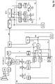
- the procedure is based on 1 explained.
- an ultrasonic burst is first generated and emitted into a free space, typically in the area surrounding the vehicle (step ⁇ of 1 ).
- An ultrasonic burst consists of several successive sound pulses with ultrasonic frequency. This ultrasonic burst is caused by a mechanical oscillator in an ultrasonic transmitter or ultrasonic transducer slowly oscillating and oscillating again.
- the ultrasonic burst thus emitted by the exemplary ultrasonic transducer is then reflected on objects in the vicinity of the vehicle and received by an ultrasonic receiver or the ultrasonic transducer itself as an ultrasonic signal and converted into an electrical reception signal (step ⁇ of 1 ).
- the ultrasound transmitter is particularly preferably identical to the ultrasound receiver and is then referred to below as a transducer.
- the proposed ultrasonic sensor contains a signal processing unit, which now analyzes and compresses the received electrical signal (step ⁇ of 1 ) for the necessary data transfer to minimize and to create free space for said status messages and other control commands from the control unit to the signal processing unit or the ultrasonic sensor system.
- the compressed electrical reception signal is then transmitted to the computer system (step ⁇ of 1 ).
- the method according to the variant described above and the advantageous configurations explained below is thus used to transmit sensor data, in particular an ultrasonic sensor, from a sensor to a computer system, in particular in a vehicle. It begins by emitting an ultrasonic burst (step ⁇ of 1 ). An ultrasonic signal is received and an electrical reception signal is formed (step ⁇ of 1 ) and carrying out a data compression of the received signal (step ⁇ of 1 ) to generate compressed data (step ⁇ of 1 ) and the detection of at least two or three or more predetermined properties.
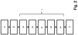
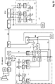
- the electrical reception signal is preferably obtained by sampling (step ya of 2 ) into a sampled received signal consisting of a time-discrete stream of samples.
- Each sample can typically be assigned a sampling time as a time stamp of this sample.
- the compression can be carried out, for example, by a wavelet transformation (step yb of 2 ) take place.
- the received ultrasonic signal in the form of the sampled reception signal can be compared with predetermined signal basic forms, which are stored in a library, for example, by forming a correlation integral (for the definition of this term, e.g. in Wikipedia) between the predetermined signal basic forms and the sampled reception signal.
- the predetermined signal basic forms are also referred to below as signal object classes.
- spectral values themselves represent a stream of time-discrete instantaneous spectral values, with each spectral value being able to be assigned a time stamp.
- An alternative but mathematically equivalent method is to use Optimal filters (English matched filter) for each predetermined signal object class (signal basic form). Since, as a rule, several prototypical signal object classes are used, which can also be subjected to different time spreads, this typically results in a time-discrete stream of multidimensional vectors of spectral values of different prototypical signal object classes and their different respective time spreads, with each of these multidimensional vectors again having a timestamp is assigned. Each of these multidimensional vectors is a so-called feature vector. It is therefore a time-discrete stream of feature vectors. A time stamp is preferably assigned to each of these feature vectors (step yb of the 2 ).
- the feature vector of the spectral values can also be supplemented by values from the past or by values that depend on them, for example time integrals or derivatives or filter values from one or more of these values, etc. This can further increase the dimension of these feature vectors within the feature vector data stream.
- the limitation to a few prototypical signal object classes during the extraction of the feature vectors from the scanned input signal of the ultrasonic sensor makes sense.
- optimal filters English matched filter
- a prototypical signal object class usually consists of a specified spectral coefficient vector, ie a specified prototypical feature vector value.
- the absolute value of a Distance of these properties the elements of the vector of the instantaneous spectral coefficients (feature vector), to at least one prototypical combination of these properties (prototype) in the form of a prototypical signal object class, which is defined by a given prototypical feature vector (prototype or prototype vector) from a library of predetermined prototypical signal object class vectors is symbolized (step yd of 2 ).
- the spectral coefficients of the feature vector are preferably normalized before correlation with the prototypes (step yc of 2 ).
- the distance determined in this distance determination can consist, for example, of the sum of all differences between a spectral coefficient of the specified prototypical feature vector (prototype or prototype vector) of the respective prototype and the corresponding normalized spectral coefficient of the current feature vector of the ultrasonic echo signal.
- a Euclidean distance would be formed by the square root of the sum of the squares of all differences between each spectral coefficient of the given prototypical feature vector (prototypes or prototype vector) of the prototype and the corresponding normalized spectral coefficient of the current feature vector of the ultrasonic echo signal.
- this spacing formation is generally too complex. Other methods of spacing are conceivable.
- a symbol and possibly also a parameter, for example the distance value and/or the amplitude before normalization, can then be assigned to each predefined prototypical feature vector (prototype or prototype vector). If the distance determined in this way falls below a first threshold value and if it is the smallest distance between the current feature vector value and one of the predefined prototypical feature vector values (prototypes or values of the prototype vectors), then its symbol is used as a recognized prototype. This results in a pairing of recognized prototypes and time stamp of the current feature vector.
- the data is then preferably transmitted (step ⁇ of 2 ), here the determined symbol that best symbolizes the recognized prototype and, for example, the distance and the time of occurrence (time stamp) to the computer system only if the amount of this distance is below the first threshold value and the recognized prototype is a prototype to be transmitted. It can be the case that prototypes that cannot be recognized, for example for noise, for example the absence of reflections, etc., are also stored. This data is irrelevant for obstacle detection and should therefore not be transmitted. A prototype is therefore recognized when the amount of the determined distance between the current feature vector value and the specified prototypical feature vector value (prototype or value of the prototype vector) is below this first threshold value (step ye der 2 ).
- an estimated value - for example, the inverse distance between the representative of the prototypical signal object class in the form of the specified prototypical feature vector (prototype or prototype vector) - and the subsequent transmission of the compressed data to the computer system if the absolute value of this estimated value (eg inverse distance) is above a second threshold value or the inverse estimated value is below a first threshold value.
- the signal processing unit of the ultrasonic sensor thus performs data compression of the received signal to generate compressed data.
- This determination of distance is also known as classification from the signal processing of statistical signals.
- classifiers are logistic regression, the cuboid classifier, the distance classifier, the nearest neighbor classifier, the polynomial classifier, the cluster method, artificial neural networks, and latent class analysis.
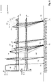
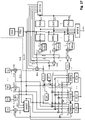
- a classifier example is in 7 shown schematically.
- a physical interface 101 controls an ultrasonic transducer 100, for example, and causes it to emit an ultrasonic transmit pulse or ultrasonic transmit burst, for example.
- the ultrasonic transducer 100 receives the from a not in 7
- the ultrasonic transmission pulse or ultrasonic transmission burst reflected by the obstacle object drawn in has an amplitude change, a delay and typically a distortion which is caused by the nature of the reflecting obstacle object.
- the ultrasonic transducer 100 converts the received reflected ultrasonic wave into an ultrasonic transducer signal 102 .
- the physical interface converts this ultrasonic transducer signal into an ultrasonic echo signal 1, typically by filtering and/or amplification.
- the feature vector extractor 111 extracts signal curve characteristics (features) from this ultrasonic echo signal 1 .
- the physical interface 101 preferably transmits the ultrasonic echo signal 1 to the feature vector extractor 111 as a time-discrete received signal consisting of a sequence of sample values. In this case, a time date (time stamp) is preferably assigned to each sampled value.
- the feature vector extractor 111 has in the example of 7 a plurality of m (where m is a positive integer) matched filters (matched filter 1 to matched filter m).
- m intermediate parameter signals 123 each relating to the presence of one of the respective intermediate parameter signals preferably assigned signal base object, preferably with the aid of a suitable filter (e.g. an optimal filter) from the sequence of sample values of the ultrasonic echo signal 1.
- the resulting intermediate parameter signals 123 are also designed as a time-discrete sequence of respective intermediate parameter signal values, each of which preferably has a date (time stamp ) are correlated. Precisely one time date (time stamp) is thus preferably assigned to each intermediate parameter signal value.
- a subsequent significance increaser 125 carries out a matrix multiplication of the vector of the intermediate parameter signal values of the intermediate parameter signal 123 with a so-called LDA matrix 126 . This is typically determined at the time of construction using methods of statistical signal processing and pattern recognition.
- the significance enhancer generates the feature vector signal 138 in this way. In doing so, it maps the m intermediate parameter signal values to n (where n is an integer) parameter signal values of the feature vector signal 138 .
- the feature vector signal thus typically comprises 138 of n parameter signals. n ⁇ m is preferred.
- feature vector is also often referred to as feature vector in statistical signal theory and in pattern recognition (also referred to below as feature vector).
- the feature vector signal 138 is thus designed, among other things, as a time-discrete sequence of feature vector signal values, each with n parameter signal values of the preferably n parameter signals of the feature vector signal 138, which the parameter signal values and further parameter signal values each have the same time date (time stamp) comprised.
- n is the dimension of the individual feature vector signal values, which are preferably equal from one feature vector value to the next feature vector value.
- a feature vector signal value is a vector with a time stamp that includes a plurality of, preferably n, parameter signal values. This respective time data (time stamp) is assigned to each feature vector signal value formed in this way.
- the evaluation of the time profile of the feature vector signal 138 in the resulting n-dimensional phase space and the closing now follows to a detected signal base object while determining an evaluation value (eg the distance).
- a distance determiner (or classifier) 112 compares the current feature vector signal value of the feature vector signal 138 with a plurality of prototype feature vector signal value prototypes previously stored in a prototype database 115 . This is explained in more detail below.
- the distance determiner (or classifier) 112 determines an evaluation value for each of the examined feature vector signal value prototypes in the prototype database 115, which indicates the extent to which the respective feature vector signal value prototype in the prototype database 115 resembles the current feature vector signal value . This evaluation value is hereinafter referred to as distance.
- the feature vector signal value prototypes are preferably each assigned to exactly one signal basic object.
- the feature vector signal value prototype of the prototype database 115 with the smallest distance to the current feature vector signal value then most closely resembles it. If the distance is less than a specified threshold value, this feature vector signal value prototype in the prototype database 115 represents the signal base object 121 recognized with the highest probability.
- This recognition process is carried out several times in succession, so that a determined signal basic object sequence results from the chronological sequence of the recognized signal basic objects 121 .
- the probable signal object 122 that is present is then determined by determining that sequence of predetermined signal basic object sequences in a signal object database 116 that is most similar to the determined signal basic object sequence.
- a signal object consists of a chronological sequence of basic signal objects.
- a symbol in the signal object database 116 is typically assigned to the signal object in a predefined manner.
- this estimation of the signal basic object sequence can be performed by a Viterbi estimator 113 .
- the Viterbi estimator determines an evaluation value for each of the predefined signal objects in the signal object database 116, the signal objects in the signal object database 116 consisting of predefined sequences of expected basic signal objects and being correlated with a respective symbol.
- the feature vector signal 138 therefore has a time profile.
- An evaluation value eg a distance
- This evaluation value which is again assigned a date (time stamp), is then preferably compared within the Viterbi estimator 113 with a threshold value vector, forming a Boolean result that can have a first and a second value.
- this Boolean result has the first value for this date (time stamp) in time
- the symbol of the signal object and the date (time stamp) assigned to this symbol are transmitted from the sensor to the computer system.
- the recognized signal object 122 is preferably transmitted with its parameters. Possibly further parameters can be transmitted depending on the detected signal object.
- the ultrasonic echo signal 1 is preferably a sequence of quantization vectors—the ultrasonic echo signal values—whose components, the measured parameters, will generally not be completely independent of one another.
- each ultrasonic echo signal value of an ultrasonic echo signal 1 by itself has insufficient selectivity for the precise determination of a signal object in complex contexts. This is precisely the deficiency in the prior art.
- the multidimensional ultrasonic echo signal value data stream is produced in the form of the ultrasonic echo signal 1.
- the multidimensional ultrasonic echo signal 1 obtained in this way in the form of one or more streams of quantization vectors is first divided into individual frames of a defined length, filtered, normalized, then orthogonalized and, if necessary, by a non-linear mapping - e.g. logarithmic processing and cepstrum analysis - suitably distorted.
- a non-linear mapping e.g. logarithmic processing and cepstrum analysis - suitably distorted.
- a significance increase of the determined intermediate parameter signal 123 takes place in a significance increase unit 125 for the actual feature vector signal 138 .
- this can be done, for example, by multiplying the multidimensional quantification sector by a so-called predetermined LDA matrix 126 .
- the components of the newly transformed feature vectors obtained in this way are not selected according to real physical or other parameters, but according to maximum significance, which results in said maximum selectivity.
- the LDA matrix 126 is previously calculated offline at the time of construction on the basis of example data streams with known signal object data sets, ie data sets that were obtained with predetermined structures of the signal curve, beforehand by means of a training step.
- the prototypes from sample data streams for the specified prototypical signal curves (prototypical signal basic objects) in the coordinates of the new parameter space are calculated in the construction phase and stored in a prototype database 115 for later recognition.
- this can also contain instructions for a computer system as to what happens in the event of successful or failed recognition of the respective signal basic object prototype is to take place.
- the computer system will be the computer system of the sensor system.
- the feature vector signal values of the feature vector signal 138 which are output by the feature extractor 111 for these prototypical signal curves of the specified signal basic objects of the ultrasonic echo signal 1 in the laboratory, are therefore saved in this prototype database 115 as signal basic object prototypes.
- dummy prototypes are generally also stored in the prototype database 115 of the basic signal object prototypes, which should largely cover all parasitic parameter combinations occurring during operation. Said basic signal object prototypes are stored in the prototype database 115.
- the distance can correspond to that in the distance finder 112 applied methods for each pairing from two different signal basic object prototypes of the prototype database 115 are determined. This then results in a minimum prototype distance. This is stored in the prototype database 115 or in the distance determiner 112, preferably also halved as half the minimum prototype distance.
- this signal basic object prototype is evaluated as recognized. From this point in time it can be ruled out that further distances to other basic signal object prototypes of the prototype database 115 calculated in the course of a continued search can supply even smaller distances. The search can then be aborted, which halves the time on average and thus saves the resources of the sensor.
- dim_cnt stands for the dimension index, which runs through up to the maximum dimension of the feature vector 138 dim.
- FV dim_cnt represents the parameter value of the feature vector signal value of feature vector 138 corresponding to index dim_cnt.
- Cb_cnt stands for the number of the signal basic object prototype in the prototype database 115.
- dim_cnt accordingly stands for the dim_cnt corresponding parameter value of the entry of the signal basic object prototype in the prototype database 115, which is assigned to the signal basic object prototype corresponding to Cb_cnt.
- Dist FV_CbE stands for the minimum Euclidean distance obtained, which is exemplary here. When searching for the smallest Euclidean distance, the number Cb_cnt that produces the smallest distance is noted.
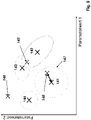
- the degree of confidence for correct recognition is derived from the scatter of the basic data streams taken as a basis for a signal basic object prototype and the distance of the current feature vector value of the feature vector signal 138 from its center of gravity.
- each feature vector signal value includes a first parameter value and a second parameter value. This is only used here to better illustrate the methodology on a two-dimensional piece of paper. In reality, the feature vector signal values of the feature vector signal 138 are typically always multidimensional.
- Focal points of various prototypes 141,142,143,144 are drawn in. As described above, half the minimum distance between these basic signal object prototypes can now be stored in the prototype database 115 in the prototype database 115 . This would then be a global parameter that would be equally valid for all signal primitive prototypes in the prototype database 115 . This decision is made using this minimum distance. However, it presupposes that the scattering of the signal basic object prototypes, which are marked by their centers of gravity 141, 142, 143, 144, are more or less identical. If the distance determination (or other evaluation) by the distance determiner 112 (or classifier) is optimal, then this is also the case. This would correspond to a circle around the center of gravity 141,142,142,144 of each of the signal basic object prototypes in the prototype database 115.
- a further improvement in the recognition performance can be achieved if the spread for the signal basic object prototype in the prototype database 115 is modeled by an ellipse.
- the main axis diameter of the scattering ellipse and its tilting relative to the coordinate system in the prototype database 115 for preferably each of the basic signal object prototypes in the prototype database 115 must be stored.
- the disadvantage is another massive increase in computing power and memory requirements.
- the position of the by the distance detector 112 in the exemplary two-dimensional parameter space 8 determined current feature vector signal values of the feature vector signal 138 can now be extremely different. It is thus conceivable that a first such feature vector signal value 146 is too far away from the center of gravity coordinates 141 , 142 , 143 , 144 of the center of gravity of any basic signal object prototype in the prototype database 115 .
- This distance threshold value can be, for example, the said minimum half prototype distance. It can also be the case that the scattering ranges of the signal basic object prototypes overlap around their respective focal points 143, 142 and, for example, a second determined current feature vector signal value 145 of the feature vector signal 138 lies in the overlapping range.
- a hypothesis list can contain both signal primitive prototypes with different probabilities as an attached parameter (for different distances). It is then not a basic signal object that is passed to the Viterbi estimator 113 as the most probable one, but rather a vector of possible basic signal objects that are present to the Viterbi estimator 113 passed. From the chronological sequence of these hypothesis lists, the Viterbi estimator then searches for the possible sequence that has the greatest probability of one of the predetermined signal basic object sequences in its signal object database compared to all possible paths through the signal basic objects 121 recognized as possible by the distance detector 112 by the Viterbi estimator 113 has received hypothesis lists. In such a path, exactly one recognized signal basic object prototype of this hypothesis list must be run through this path for each hypothesis list.
- the current feature vector signal value 148 is in the scatter range (threshold ellipsoid) 147 around the center of gravity 141 of a single signal basic object prototype 141, which is thus reliably recognized by the distance detector 112 and passed on to the Viterbi estimator 113 as a recognized signal basic object 121.
- the number of assembler instructions that must be executed to compute a vector component is approximately 8 steps.
- the smallest distance between two signal basic object prototypes in the prototype database 115 is precalculated and stored in the prototype database 115 or in the distance detector 112.
- the mean search time for the distance finder 112 is thus halved.
- Further optimizations can be undertaken if the prototype database 115 is sorted according to the statistical occurrence of the signal basic object prototypes in real ultrasonic echo signals 1 . In this way it can be ensured that the most frequent signal basic object prototypes are found much faster, which further shortens the computing time of the distance determiner or classifier 112 and further reduces the power consumption.
- a _ cb cb _ no *
- a _ distance + 4 cb _ no * FV _ dimensions * 8th + 10 + 4
- the two additional assembler commands are necessary to check whether the determined distance between the current feature vector signal value and the currently examined signal basic object prototype of the prototype database 115 is below half the smallest distance between the signal basic object prototypes of the prototype database 115.
- the number CB_Anz of signal basic object prototype entries in the prototype database 115 for mobile and energy self-sufficient applications is limited to 4000 prototype database entries of signal basic object prototypes in the prototype database 115 or even less.
- the number of feature vector signal values per second within feature vector signal 138 is reduced by filtering in feature vector extractor 111 and lowering the sampling rate in feature vector extractor 111 .
- Said distance finder or classifier 112 which executes an average HMM detection method, is now used with a prototype database 115 with just under a tenth of the entries, e.g. with 4000 entries CbE and furthermore with 24 feature vector signal dimensions (i.e. 24 parameter signals) operated.
- the search is terminated when the distance of the current feature vector signal value to the processed signal basic object prototype of the prototype database 115 is below half the smallest prototype database entry distance, the effort is at least halved with suitable sorting of the prototype database 115.
- the search area can be restricted by pre-selection.
- the need to reduce the size of the prototype database 115 has advantages and disadvantages: A reduction in the number of entries in the prototype database 115 increases both the false acceptance rate FAR, i.e. the wrong signal basic object prototypes that are accepted as signal basic object prototypes, and the false rejection rate FRR, i.e. the signal basic object prototypes that are actually present that are not recognized.
- FAR false acceptance rate
- FRR false rejection rate
- the previous history i.e. the previously recognized signal basic object prototypes
- the distance determiner 112 can be used by the distance determiner 112 when forming hypotheses.
- a suitable model for this is the so-called Hidden Markov Model HMM.
- a confidence level and a distance from the measured current feature vector signal value of the feature vector signal 138 can thus be derived for each signal basic object prototype, which can also be further processed by the Viterbi estimator 113 . It also makes sense to output a list of hypotheses for each of the detected basic signal object prototypes 121, which list contains, for example, the ten most probable basic signal object prototypes with the respective probability and reliability of the detection.
- Viterbi estimator 113 Since not every temporal and spatial signal basic object sequence can be assigned to a signal object, it is possible to use a Viterbi estimator 113 to evaluate the chronological succession of the hypothesis lists of the subsequent frames.
- the signal basic object prototype sequence path through the consecutive hypothesis lists that has the highest probability and is present in the signal object database 116 of the Viterbi estimator 113 is to be found.
- such a prototype can be entered into a signal object database 116 using a learning program in the form of an entry consisting of a predetermined sequence of signal basic object prototypes; allows a keyboard.
- the most probable of the predefined sequences of signal basic object prototypes for a sequence of recognized signal basic object prototypes 121 can be determined from the sequence of the hypothesis lists of the distance determiner or the classifier 112. This also applies in particular if individual signal basic object prototypes were incorrectly recognized by the distance detector or the classifier 112 due to measurement errors. In this respect, it is very useful for the Viterbi estimator 113 to take over sequences of signal basic object prototype hypothesis lists from the distance determiner or classifier 112, as described above. The result is the signal object 122 recognized as the most probable or, analogously to the previously described emission calculation of the distance estimator or classifier 112, a signal object hypothesis list.
- Viterbi estimator 113 search accesses the signal object database 116 .
- the signal object database 116 is fed on the one hand by a learning tool and on the other hand by a tool in which these sequences of signal basic object prototypes can be defined by textual input. The possibility of a download in production is only mentioned here for the sake of completeness.
- the basis of the sequence recognition for the time sequence of the signal basic object prototypes in the Viterbi estimator 119 is a hidden Markov model, for example.
- the model is made up of different states. in the in 9 given example, these states are symbolized by numbered circles. In the example in question 9 the circles are numbered from Z1 to Z6. In between the states have transitions. These transitions are in the 9 denoted by the letter a and two indices i, j.
- the first index i designates the number of the source node, the second index j the number of the destination node.
- there are also transitions a ii or a jj which lead back to the start node.
- a probability of actually observing a k-th observable b k results from the sequence. This results in sequences of observables that can be observed with probabilities bk that can be calculated in advance.
- Every Hidden Markov Model consists of unobservable states q i .
- the transition probability aij exists between two states q i and q j .
- n stands for a discrete point in time. The transition thus takes place between step n with state q i and step n+1 with state q j .
- the emission distribution b i (Ge) depends on the state q i . As already explained, this is the probability of observing the elementary gesture Ge (the observable) when the system (Hidden Markov Model) is in state q i : p ge
- the initial states must be defined. This is done by a probability vector ⁇ i . Then it can be stated that a state q i with probability ⁇ i is an initial state: p q i 1 ⁇ ⁇ i
- a new model must be created for each sequence of signal primitive object prototypes.
- the observation probability for a temporal observation sequence of signal basic object prototypes G e ⁇ ge 1 , ge 2 , ... ge N to be determined.
- the probability p, dependent on the model M, the temporal sequence of states Q and the temporal observation sequence Ge, of observing this sequence of states Q is: p G e ⁇
- Q ⁇ , M p ge 1 , ge 2 , ... ge N
- q 1 , q 2 , ... .. q N p ge 1
- the probability of detecting a signal object is equal to a sequence of basic signal object prototypes (see also 10 ): p G e ⁇
- M j ⁇ Alles Q k p G e ⁇
- the most probable signal object model (signal object) for the observed emission Ge is determined by this summation of the individual probabilities over all possible paths Q k that lead to this observed sequence of signal basic object prototypes Ge.
- M j ⁇ Alles Q k p G e ⁇
- the calculation is carried out by recursive calculation.
- the probability of this path is a mathematical product. Therefore, a logarithmic calculation reduces the problem to a pure summation problem.
- the probability of detecting a signal object which corresponds to the detection of a model M j , corresponds to the determination of the most probable signal object model for the observed emission X. This is now carried out exclusively via the best possible path Q best p G e ⁇
- prototype database 115 contains only signal primitive prototypes.
- the detected signal objects are transmitted with the detected parameters instead of the samples. This leads to a compression of the data without leaving the signal character.
- the ultrasonic sensor then transmits the data compressed in this way, preferably only the codes (symbols) of the prototypes recognized in this way, their amplitude and/or time extension and the time of occurrence (time stamp), to the computer system.
- this prioritization does not relate to the prioritization relative to other bus users.
- the data connection between the sensor and the computer system of the vehicle is usually a point-to-point connection. Rather, the prioritization is to be understood here in terms of which datum of the data ascertained by the sensor system must be transmitted as the first control unit in terms of time.
- Reports of safety-critical errors from the sensor to the computer system have the highest priority, since they are highly likely to affect the validity of the measurement data from the ultrasonic sensor.
- This data is sent from the sensor to the computer system.
- Requests from the computer system to carry out safety-related self-tests have the second highest priority. Such commands are sent from the computer system to the sensor.
- the third-highest priority is the data from the ultrasonic sensor itself, since the latency must not be increased. All other data has lower priority for transmission over the data bus.
- the method for transmitting sensor data in particular from an ultrasonic sensor, from a sensor to a computer system, in particular in a vehicle, comprising the transmission of an ultrasonic burst with a beginning 57 and end 56 of the transmission of the ultrasonic burst and comprising receiving an ultrasonic signal and forming a received signal for a receiving time T E at least from the end 56 of the Transmission of the ultrasonic burst and including the transmission of the compressed data via a data bus, in particular a single-wire data bus, to the computer system is designed in such a way that the transmission 54 of the data from the sensor to the computer system is started with a start command 53 from the computer system to the ultrasonic sensor via the Data bus and before the end 56 of the transmission of the ultrasonic burst begins or after a start command 53 from the computer system to the sensor via the data bus and before the beginning 57 of the transmission of the ultrasonic burst begins.
- the transmission 54 then takes place periodically after the start command 53 until the end of the data
- a further variant of the proposed method thus provides for the formation of a feature vector signal (stream of feature vectors with n feature vector values and n as the dimension of the feature vector) from the received signal as the first step in data compression.
- a feature vector signal can include multiple analog and digital data signals. It therefore represents a chronological sequence of more or less complex data/signal structures. In the simplest case, it can be understood as a vectorial signal consisting of several partial signals.
- An envelope signal of the received signal (ultrasonic echo signal) can also be formed, which can then be a partial signal within the feature vector signal 138 .
- the signal can be used as an emitted ultrasonic signal, which was used to control the driver for the transmitter, or on the other hand, for example, a signal that was measured at the transmitter and thus corresponds better to the sound wave actually emitted can be used.
- a matched filter is a filter that optimizes the signal-to-noise ratio (SNR).
- SNR signal-to-noise ratio
- the predefined signal objects are to be recognized in the disturbed ultrasound reception signal.
- correlation filter, signal-matched filter (SAF) or just matched filter are also frequently found in the literature.
- the matched filter is used to optimally determine the presence (detection) of the amplitude and/or location of a known waveform, i.e. the predetermined signal object, in the presence of noise (parameter estimation). This interference can be, for example, signals from other ultrasonic transmitters and/or ground echoes.
- the optimal filter output signals are then preferably partial signals within the feature vector signal.
- Certain events can be signaled in separate partial signals of the feature vector signal. These events are signal primitives within the meaning of this invention. Signal basic objects therefore do not include signal shapes, such as square pulses or wavelets or wave trains, but prominent points in the course of the received signal and/or in the course of signals derived from it, such as an envelope signal (ultrasonic echo signal), which, for example, by filtering can be obtained from the received signal.
- an envelope signal ultrasonic echo signal
- Another signal which can be a partial signal of the feature vector signal, can signal, for example, whether the envelope of the received signal, the Ultrasonic echo signal crosses a predetermined third threshold. It is therefore a signal that signals the presence of a signal basic object within the received signal and thus the feature vector signal.
- Another signal which can be a partial signal of the feature vector signal, can signal, for example, whether the envelope of the received signal, the ultrasonic echo signal, crosses a predetermined fourth threshold value, which can be identical to the third threshold value, in an ascending manner. It is therefore a signal that signals the presence of a signal basic object within the received signal and thus the feature vector signal.
- Another signal which can be a partial signal of the feature vector signal, can signal, for example, whether the envelope of the received signal, the ultrasonic echo signal, falls below a predetermined fifth threshold value, which can be identical to the third or fourth threshold value crosses. It is therefore a signal that signals the presence of a signal basic object within the received signal and thus the feature vector signal.
- Another signal which can be a partial signal of the feature vector signal, can signal, for example, whether the envelope of the received signal, the ultrasonic echo signal, has a maximum above a sixth threshold value that is identical to the aforementioned third to fifth threshold values can, has. It is therefore a signal that signals the presence of a signal basic object within the received signal and thus the feature vector signal.
- Another signal which can be a partial signal of the feature vector signal, can signal, for example, whether the envelope of the received signal, the ultrasonic echo signal, has a minimum above a seventh threshold value, which is identical to the aforementioned third to sixth threshold values can, has. It is therefore a signal that signals the presence of a signal basic object within the received signal and thus the feature vector signal.
- the at least one preceding maximum of the ultrasonic echo signal is at a minimum distance from the minimum in order to avoid detection of noise.
- Other filters are conceivable at this point.
- It can also be checked whether the time interval between this minimum and a preceding maximum is greater than a first minimum time interval. The fulfillment of these conditions sets a flag or signal, which itself is preferably a partial signal of the feature vector signal.
- the feature vector signal can also be transformed into a significant feature vector signal, e.g. by a linear mapping or a matrix polynomial of a higher order, in a significance increase stage. In practice, however, it has been shown that this is not yet necessary, at least for today's requirements.
- signal objects are recognized and classified into recognized signal object classes within the received signal on the basis of the feature vector signal or the significant feature vector signal.
- the signal object for which the optimal filter is designed to detect can be considered recognized.
- other parameters are preferably also taken into account. For example, an ultrasonic burst was sent with increasing frequency during the burst (called chirp-up), an echo is also expected that has this modulation property.
- the signal form of the ultrasonic echo signal for example a triangular signal form of the ultrasonic echo signal
- the system can then differentiate between intrinsic echoes and extraneous echoes, as a result of which one and the same signal form is assigned to two different signal objects, namely intrinsic echoes and extraneous echoes.
- the transmission of the intrinsic echoes via the data bus from the sensor to the computer system preferably takes place with priority over the transmission of the external echoes, since the former are generally relevant to safety and the latter are generally not relevant to safety.
- At least one signal object parameter is assigned to each recognized signal object or is determined for this signal object.
- This is preferably a time stamp that indicates when the signal object was received.
- the time stamp can relate, for example, to the time at which the signal object begins in the received signal or the time it ends or the time position of the time focus of the signal object, etc.
- Other signal object parameters such as amplitude, aspect ratio, etc. are also conceivable.
- at least one of the assigned signal object parameters is thus transmitted together with a symbol for the at least one recognized signal object class.
- the signal object parameter is preferably a time value as a time stamp and specifies a time position that is suitable for being able to deduce the (receipt) time since the transmission of a previous ultrasonic burst.
- a determined distance of an object is preferably determined from this later as a function of a time value determined and transmitted in this way.
- the prioritized transmission of the recognized signal object classes follows in the form of associated symbols with time stamps, preferably together with the associated signal object parameters.
- the transfer can also in more complex data structures (records). For example, it is conceivable to first transmit the times of the recognized safety-relevant signal objects (eg identified obstacles) and then the recognized signal object classes of the safety-relevant signal objects. This further reduces the latency.
- the method according to the invention comprises at least one variant of determining a chirp value as an associated signal object parameter which indicates whether the detected signal object is an echo of an ultrasonic transmission burst with a chirp up or a chirp down or a no-chirp property.
- Chirp-up means that the frequency of the received signal increases within the signal object.
- Chirp down means that the frequency of the received signal falls within the signal object.
- No-chirp means that the frequency of the received signal remains essentially the same within the signal object.
- a confidence signal is thus also generated by forming the correlation, e.g. by forming a time-continuous or time-discrete correlation integral, between the received signal or instead of the received signal with a signal derived from the received signal on the one hand and a reference signal, for example the ultrasonic transmission signal or another expected wavelet, on the other hand.
- the confidence signal is then typically a partial signal of the feature vector signal, that is to say a component of the feature vector which consists of a sequence of vector sampling values (feature vector values).
- a phase signal is also formed on this basis, which indicates the phase shift, for example of the received signal or a signal formed therefrom (e.g. the confidence signal) compared to a reference signal, for example the ultrasonic transmission signal and/or another reference signal.
- the phase signal is then typically also a partial signal of the feature vector signal, ie a component of the feature vector, which consists of a sequence of vector samples.
- a phase confidence signal can be formed by forming the correlation between the phase signal or a signal derived therefrom and a reference signal and used as a partial signal of the feature vector signal.
- the phase confidence signal is then typically also a partial signal of the feature vector signal, that is to say a component of the feature vector, which consists of a sequence of vector samples.
- phase confidence signal When evaluating the feature vector signal, it can then be useful to compare the phase confidence signal with one or more threshold values to generate a discretized phase confidence signal, which itself is again a partial signal of the feature vector signal can be.
- the feature vector signal and/or the significant feature vector signal can be evaluated in such a way that one or more distance values are formed between the feature vector signal and one or more signal object prototype values for recognizable signal object classes .
- a distance value can be boolean, binary, discrete, digital or analog. All distance values are preferably combined with one another in a non-linear function.
- a received chirp-down echo in the form of a triangle can be discarded. This discarding is a non-linear process within the meaning of the invention.
- the triangle in the received signal can be different.
- this affects the amplitude of the triangle in the received signal.
- the optimum filter assigned to this triangular signal supplies a signal above a predetermined one ninth threshold.
- this signal object class can be assigned to a recognized signal object at the time it was exceeded.
- At least one signal object class is wavelets, which are estimated and thus detected by estimation devices (e.g. optimal filters) and/or estimation methods (e.g. estimation programs running in a digital signal processor).
- estimation devices e.g. optimal filters
- estimation methods e.g. estimation programs running in a digital signal processor.
- wavelet designates functions that can be used as a basis for a continuous or a discrete wavelet transformation.
- the word "wavelet” is a neologism of the French “ondelette” meaning "small wave” and translated into English partly literally (“onde” ⁇ "wave”) and partly phonetically (“-lette” ⁇ "-let”) became.
- wavelet was coined in the 1980s in geophysics (Jean Morlet, Alex Grossmann) for functions that generalize the short-time Fourier transform, but since the late 1980s it has been used exclusively in its current meaning.
- 1990s there was a veritable wavelet boom, triggered by the discovery of compact, continuous (up to any order of differentiability) and orthogonal wavelets by Ingrid Daubechies (1988) and the development of the fast wavelet transform (FWT) algorithm using MultiResolution Analysis (MRA) by Stephane Mallat and Yves Meyer (1989).
- MRA MultiResolution Analysis
- wavelets that have an integral other than 0 should also be permissible.
- the rectangular and triangular wavelets described below should be mentioned here as an example. This further interpretation of the term "wavelet” is widespread in the American language area and is therefore well known. This further interpretation should also apply here.
- wavelets with an integral of 0 are the Haar wavelet (Alfred Haar 1909), the Daubechies wavelets named after Ingrid Daubechies (around 1990), the Coiflet wavelets also constructed by her and the more theoretically significant Meyer wavelet ( Yves Meyer, around 1988).
- wavelets for spaces of any dimension usually a tensor product of a one-dimensional wavelet basis is used. Due to the fractal nature of the two-scale equation in MRA, most wavelets have complicated shapes, most are not closed-form. This is of particular importance because the feature vector signal mentioned above is multidimensional and therefore allows the use of multidimensional wavelets for signal object detection.
- a special variant of the proposed method is therefore the use of multidimensional wavelets with more than two dimensions for signal object detection.
- the use of appropriate optimal filters to detect such wavelets with more than two dimensions is proposed, to optionally supplement the feature vector signal with further partial signals suitable for recognition.
- a particularly suitable wavelet is, for example, a triangular wavelet. This is characterized by a start time, a temporally essentially linear increase in the wavelet amplitude up to a maximum of the amplitude and a temporally following the maximum of the triangular wavelet, an essentially linear decrease in the wavelet amplitude up to a end of the triangle wavelet.
- a rectangular wavelet is characterized by a starting point in time of the rectangular wavelet, which is followed by an increase in the wavelet amplitude with a first temporal steepness up to a first plateau point in time.
- the first plateau time of the rectangular wavelet is followed by a persistence of the wavelet amplitude with a second steepness of the wavelet amplitude up to a second plateau time of the rectangular wavelet.
- the second plateau point in time is followed by a fall with a third steepness over time up to the end of the rectangular wavelet.
- the amount of the second slope over time is less than 10% of the amount of the first slope over time and less than 10% of the amount of the third slope over time.
- the time shift of the relevant wavelet of the recognized signal object is used as a signal object parameter. For example, this shift can be determined by correlation. It is further proposed that when wavelets are used, the point in time at which the level of the output of an optimal filter suitable for detecting the relevant wavelet is exceeded is preferably used via a predefined tenth threshold value for this signal object or this wavelet.
- the ultrasonic echo signal (the envelope curve) of the received signal and/or a phase signal and/or a confidence signal etc. are preferably evaluated.
- Another possible signal object parameter that can be determined is a temporal compression or expansion of the relevant wavelet of the detected signal object. Likewise, an amplitude of the wavelet of the detected signal object can be determined.
- the recognition process can be assigned to the various signal objects that come into question for a section of the received signal, which score values indicate which probability is assigned to the presence of this signal object in accordance with the estimation algorithm used.
- score values can be assigned to the various signal objects that come into question for a section of the received signal, which score values indicate which probability is assigned to the presence of this signal object in accordance with the estimation algorithm used.
- Such a score value is binary in the simplest case.
- the score is preferably a complex, real or integer number. It can be the determined distance, for example.
- the data of the recognized signal object class and the assigned data such as time stamps and score values of the respective recognized signal object classes, ie the assigned signal object parameters, are preferably transmitted according to the first-in-first-out (FIFO) principle. This ensures that the data of the reflections of the closest objects are always transmitted first, so that the safety-critical case of the vehicle colliding with an obstacle is prioritized according to probability.
- FIFO first-in-first-out
- error states of the sensor can also be transmitted. This can also happen during a reception time T E , when the sensor uses self-test devices to determine that there is a defect and that the previously transmitted data could potentially be faulty. This ensures that the computer system can learn about a change in the evaluation of the measurement data at the earliest possible point in time and can discard it or treat it differently. This is of particular importance for emergency braking systems, since emergency braking is a safety-critical intervention that may only be initiated if the underlying data has a corresponding trust value.
- the transmission of the measurement data ie, for example, the date of the recognized signal object class and/or the transmission of the at least one assigned signal object parameter, is therefore postponed and therefore given a lower priority.
- the transmission would be aborted if an error occurred in the sensor. In some cases, however, it can also be the case that an error appears possible but is not definitely present. In this respect, the continuation of a transfer may be indicated in such cases.
- the Sensor errors that are critical to safety are therefore preferably transmitted with a higher priority.
- certain points in time in the course of the received signal can also be considered as a basic signal object within the meaning of the invention, which can be used for data compression and instead of samples of the received signal can be transmitted.
- This subset in the set of possible signal basic objects is referred to below as signal instants.
- the signal instants are therefore a special form of the signal basic objects within the meaning of the invention.
- a first possible signal point in time and thus a basic signal object is when the amplitude of the ultrasonic echo signal 1 crosses the amplitude of an eleventh threshold value signal SW in an increasing direction.
- a second possible signal point in time and thus a basic signal object is when the amplitude of the ultrasonic echo signal 1 crosses the amplitude of a twelfth threshold value signal SW in a descending direction.
- a third possible signal point in time and thus a signal base object is a maximum of the amplitude of the ultrasonic echo signal 1 above the amplitude of a thirteenth threshold value signal SW.
- a fourth possible signal point in time and thus a signal base object is a minimum of the amplitude of the ultrasonic echo signal 1 above the amplitude of a fourteenth threshold value signal SW.
- signal-time-type-specific threshold value signals SW may be used for these four exemplary types of signal times and for other types of signal times.
- the signal object of a triangular wavelet consists of the predefined sequence of three basic signal objects, which are recognized and replaced by a symbol and are preferably transmitted as this symbol together with the time of its occurrence, the time stamp.
- this exceeding of the said minimum level at the output of the said optimal filter is a further example of a fifth possible signal point in time and thus a further possible signal basic object.
- the resulting grouping and chronological sequence of detected basic signal objects can itself, for example by a Viterbi decoder, as a predefined, expected grouping or chronological sequence of basic signal objects recognized and can thus represent a basic signal object itself.
- a sixth possible signal point in time and thus a basic signal object is the occurrence of such a predefined grouping and/or chronological sequence of other basic signal objects.
- the symbol of this recognized summary signal object class and at least one assigned signal object parameter are preferably transmitted instead of the transmission of the individual basic signal objects, since this saves considerable data bus capacity.
- the data (symbol) of the signal object class of a signal object is transmitted, which is a predefined time sequence and/or grouping of other signal basic objects.
- at least one signal object class (symbol) of at least one of these other signal basic objects is not transmitted.
- a chronological grouping of basic signal objects is present in particular when the chronological distance between these basic signal objects does not exceed a predefined distance.
- the propagation time of the signal in the matched filter should be considered.
- the matched filter should be slower than the comparators.
- the change in the output signal of the optimum filter should therefore be in a fixed temporal relationship to the occurrence of the relevant signal times.
- a method is therefore proposed here for the transmission of sensor data, in particular an ultrasonic sensor, from a sensor to a computer system, in particular in a vehicle, which starts with the transmission of an ultrasonic burst and the reception of an ultrasonic signal and the formation of a time-discrete received signal consisting of a sequence of samples begins.
- a date time stamp
- At least two parameter signals are determined in each case relating to the presence of a basic signal object assigned to the respective parameter signal with the aid of at least one suitable filter (eg an optimal filter) from the sequence of samples of the received signal.
- the resulting parameter signals are also in the form of a time-discrete sequence of respective parameter signal values (feature vector values), which are each correlated with a date (time stamp).
- each parameter signal value feature vector value
- These parameter signals together are referred to below as the feature vector signal.
- the feature vector signal is thus in the form of a time-discrete sequence of feature vector signal values each having n parameter signal values, which consist of the parameter signal values and further parameter signal values each having the same date (time stamp).
- n is the dimensionality of the individual feature vector signal values, which are preferably the same from one feature vector value to the next feature vector value.
- This respective time data (time stamp) is assigned to each feature vector signal value formed in this way.
- a signal object consists of a chronological sequence of basic signal objects. A predefined symbol is typically assigned to the signal object. In other words, it is checked here whether the point to which the n-dimensional feature vector signal in the n-dimensional phase space points, on its way through the n-dimensional phase space in a predetermined time sequence, is at predetermined points in this n-dimensional phase space closer than a predetermined maximum distance approaches.
- the feature vector signal thus has a time profile.
- An evaluation value (eg a distance) is then calculated, which can, for example, reflect the probability of the existence of a specific sequence.
- This evaluation value which is again assigned a date (time stamp) is then compared with a threshold value vector, forming a Boolean result that can have a first and a second value. If this boolean result for this date in time (timestamp) has the first value, the symbol of the signal object and the date (time stamp) associated with this symbol are transmitted from the sensor to the computer system. If necessary, further parameters can be transmitted depending on the detected signal object.
- the reconstruction of a reconstructed ultrasonic echo signal model 610 from the detected signal objects 122 is particularly advantageous.
- This ultrasonic echo signal model 610 is generated from the summing linear superimposed signal curve models of the individual detected signal objects. It is then subtracted from the ultrasonic echo signal 1. A residual signal 660 is thereby formed.
- signal objects similar to the selected signal object recognized with a higher probability are better suppressed.
- the weaker signal objects stand out better in the residual signal 660 and can be recognized better (see also 18 ).
- a subtraction of the ultrasonic echo signal model 610 reconstructed from the detected signal objects from the ultrasonic echo signal 1 to form a residual signal 660 is therefore preferably also provided.
- the residual signal 660 formed in this way is then used again to form the feature vector signal 138 and the next signal object is recognized with the next higher probability. Since the signal object recognized first was removed from the input signal according to its weighting, it can no longer influence this recognition. Thus, this form of recognition delivers a better result.
- this detection method is usually slower. Therefore, it makes sense to carry out a first direct object recognition without subtraction while the measurement is still running and then, after recording all sampled values of an ultrasonic echo response of the surroundings of the vehicle, after the emission of an ultrasonic pulse or an ultrasonic burst, a repeated pattern recognition with subtraction of the Ultrasonic Echo Signal Model 610, which takes longer but is more accurate.
- this reducing classification of the ultrasonic echo signal 1 into signal objects using the ultrasonic echo signal model 610 is then ended, when the magnitudes of the samples of the residual signal 660 are below the magnitudes of a predetermined threshold curve.
- the data is transmitted in the vehicle via a serial, bidirectional single-wire data bus.
- the electrical return line is preferably ensured by the body of the vehicle.
- the sensor data are preferably sent to the computer system in a current-modulated manner.
- the data for controlling the sensor are preferably sent to the sensor in voltage-modulated form by the computer system. It was recognized that the use of a PSI5 data bus and/or a DSI3 data bus is particularly suitable for data transmission. Furthermore, it was recognized that it is particularly advantageous to transmit the data to the computer system at a transmission rate of> 200 kbit/s and from the computer system to the at least one sensor at a transmission rate> 10 kbit/s, preferably 20 kbit/s .
- the transmission of data from the sensor to the computer system should be modulated with a transmission current on the data bus, the current strength of which should be less than 50 mA, preferably less than 5 mA, preferably less than 2.5 mA.
- the current strength of which should be less than 50 mA, preferably less than 5 mA, preferably less than 2.5 mA.
- the proposed method for transmitting sensor data is carried out as follows: It begins by emitting an ultrasonic burst. An ultrasonic signal is then received, ie typically a reflection and the formation of a time-discrete received signal consisting of a temporal sequence of sampled values. A date (time stamp) is assigned to each sample. This typically reflects the time of sampling. On the basis of this data stream, a first parameter signal of a first property is determined with the aid of a first filter from the sequence of samples of the received signal.
- the parameter signal is preferably in the form of a time-discrete sequence of parameter signal values.
- Exactly one date is assigned to each parameter signal value.
- This date preferably corresponds to the most recent chronological date of a sample value that was used to form this respective parameter signal value.
- At least one other is preferably determined at the same time parameter signal of a property assigned to this additional parameter signal using an additional filter assigned to this additional parameter signal from the sequence of sampled values of the received signal, the additional parameter signals each being in the form of time-discrete sequences of additional parameter signal values.
- each additional parameter signal value is assigned the same time date (time stamp) as the corresponding parameter signal value.
- the first parameter signal and the further parameter signals are collectively referred to below as a feature vector signal.
- This feature vector signal (or also parameter vector signal) thus represents a time-discrete sequence of feature vector signal values, which consist of the parameter signal values and further parameter signal values each with the same chronological date (time stamp).
- time stamp a chronological date
- each feature vector signal value formed in this way can be assigned this respective time data (time stamp).
- the feature vector signal values of a date are then preferably compared quasi-continuously with a threshold vector, which is preferably a prototype vector, with formation of a Boolean result that can have a first and a second value.
- a threshold vector which is preferably a prototype vector
- Boolean result that can have a first and a second value.
- the Boolean result has a first value
- all further feature vector signal values can be checked.
- Other classifiers are also conceivable.
- a comparison with several different threshold value vectors is also possible. These threshold value vectors therefore represent the prototypes of predetermined signal forms. They come from the said library. A symbol is again preferably assigned to each threshold value vector.
- the last step in this case is the transmission of the symbol and possibly also the feature vector signal values and the time date (time stamp) assigned to the symbol or the feature vector signal value from the sensor to the computer system if the Boolean result has the first value for this chronological date (time stamp).
- a sensor system is therefore proposed, with at least one computer system that is able to carry out one of the methods presented above and with at least two sensors that are also able to carry out one of the methods presented above, so that these at least two Sensors can communicate with the computer system through signal object detection and are also able to transmit extraneous echoes in a compact form and to provide this additional information to the computer system.
- the sensor system is typically provided for the data transmission between the at least two sensors and the computer system to take place or be able to take place in accordance with the methods described above.
- one ultrasound reception signal ie at least two ultrasound reception signals, is typically compressed using one of the previously proposed methods and transmitted to the computer system.
- the at least two received ultrasound signals become reconstructed received ultrasound signals within the computer system reconstructed.
- the computer system then carries out object recognition of objects in the vicinity of the sensors with the aid of reconstructed ultrasound reception signals. In contrast to the prior art, the sensors do not carry out this object recognition.
- the computer system preferably additionally carries out an object recognition of objects in the vicinity of the sensors with the aid of the reconstructed ultrasound reception signals and additional signals from other sensors, in particular the signals from radar sensors.
- the computer system preferably creates an environment map for the sensors or a device, of which the sensors are a part, based on the detected objects.
- the proposed ultrasonic sensor system thus preferably comprises an ultrasonic transducer 100, a feature extractor 111 and with an estimator 150, 151 or classifier and a physical interface 101.
- the ultrasonic transducer 100 is preferably provided and/or set up to receive an acoustic ultrasonic wave signal and an ultrasonic transducer signal dependent thereon 102 to form.
- the feature vector extractor 111 is provided and/or set up to form a feature vector signal 138 from the ultrasonic transducer signal 102 .
- the ultrasonic sensor system is preferably set up and provided to use the estimator 151, 150 to recognize signal objects in the ultrasonic echo signal 1 and to classify them into signal object classes, with a signal object class also being able to include only one signal object.
- Each signal object 122 thus recognized and classified is preferably assigned at least one assigned signal object parameter and a symbol corresponding to the signal object class assigned to this signal object, or at least one assigned signal object parameter and a symbol for this signal object are determined for each signal object 122 thus recognized and classified. At least the symbol of a recognized signal object class 122 and at least the one associated signal object parameter of this recognized signal object class 122 are transmitted to a higher-level computer system via a data bus.
- the estimator 150 preferably has a distance determiner 112 and a prototype database 115 . Likewise, the estimator 150 preferably has a Viterbi estimator and a signal object database. Also, the estimator 151 can use a neural network model.
- the compression method described above corresponds to an associated decompression method, which is preferably used for decompressing ultrasonic reception data compressed and transmitted in this signal-object-oriented manner in the control computer after they have been received from the sensor via the data bus.
- an ultrasonic echo signal model is provided, which initially has no signal ( Figure 15a ).
- This ultrasonic echo signal model is now slowly filled in for each signal object by successive addition of the respective prototypical, parameterized signal curve of the signal objects 160 contained in the ultrasonic reception data, and the ultrasonic echo signal model 610 is approximated to the measured signal curve.
- the reconstructed received ultrasonic signal is preferably formed from the summed up signal courses of the signal courses of the prototypical signal objects recognized by the sensor on the basis of the ultrasonic echo signal model in the control computer of the sensor. echo signal) can happen.
- This reconstructed ultrasonic reception signal (reconstructed ultrasonic echo signal) can then be used much better in the control computer for more complicated processes such as sensor fusion than supposed obstacle object data, which are transmitted from the sensor to the control unit.
- Such a compressed transmission of data via the data bus between the sensor and the computer system reduces the data bus load and thus the criticality with regard to EMC requirements and also creates free data bus capacities, e.g. during the reception time for the transmission of control commands from the computer system to the sensor and for the transmission of status information and other data from the sensor to the computer system.
- the proposed prioritization ensures that security-relevant data are transmitted first so that there are no unnecessary dead times for the sensor.
- Figure 3a shows the course over time of a conventional ultrasonic echo signal 1 and its conventional evaluation in freely selected units for the coordinate system axes.
- a threshold value signal SW is carried along.
- the envelope signal (ultrasonic echo signal 1) of the ultrasonic received signal exceeds the threshold signal SW, the output 2 is set to logical 1. It is a temporal analog interface with a digital output level. The further evaluation is then taken over in the control unit of the sensor. Signaling errors or controlling the sensor is not possible via this analog interface, which corresponds to the prior art.
- Figure 3b shows the course over time of a conventional ultrasonic echo signal 1 and its conventional evaluation in freely selected units for the coordinate system axes.
- a threshold value signal SW is carried along.
- the envelope signal (ultrasonic echo signal 1) of the ultrasonic received signal exceeds the threshold value signal SW, the output 2 is now set to a level corresponding to the amplitude of the detected reflection. It is a temporal analog interface with an analog output level.
- the further evaluation is then taken over in the control unit of the sensor. A signalling of errors or control of the sensor is not possible via this analog interface, which corresponds to the state of the art.
- 3d the principle of symbolic signal transmission is explained. Instead of the signal off 3c only two types of triangle objects are transferred here as an example. Specifically, these are a first triangle object A for the chirp-up case and a second triangle object B for the chirp-down case. At the same time, the point in time and the amplitude of the triangular object are transmitted. If the signal is now reconstructed on the basis of this data, a corresponding signal is obtained 3d . The signal components that did not correspond to the triangular signals were removed from this signal. This means that unrecognized signal components are discarded and data is massively compressed.
- Figure 4e shows the conventional analog transmission of the points of intersection of the ultrasonic echo signal 1 of the ultrasonic received signal with the threshold signal SW.
- Fig. 4f shows the transmission of analyzed data after complete reception of the ultrasonic echo.
- Fig. 4g shows the transmission of compressed data, with symbols for signal basic objects being transmitted largely without compression in this example.
- Figure 5h shows the transmission of compressed data, symbols for signal basic objects being compressed into symbols for signal objects in this example.
- a first triangular object 59 is recognized and transmitted with a time sequence of exceeding a threshold value, which characterizes this, followed by a maximum and falling below a threshold value.
- a double peak with saddle point 60 above the threshold signal is detected.
- distinctive Here is the sequence of the threshold value signal SW being exceeded by the ultrasonic echo signal 1 followed by a maximum of the ultrasonic echo signal 1 followed by a minimum above the threshold value signal SW followed by a maximum above the threshold value signal SW followed by falling below the threshold value signal SW
- the symbol for this double peak with saddle point is transmitted.
- a time stamp is also transmitted.
- Other parameters of the double peak with saddle point are preferably also transmitted, such as the positions of the maxima and the minimum or a scaling factor.
- a triangular signal is then recognized again as the signal base object as the threshold value signal SW being exceeded by the ultrasonic echo signal 1, followed by a maximum of the ultrasonic echo signal 1, followed by the threshold value signal SW being undershot by the ultrasonic echo signal 1.
- a double peak is then recognized again, but the minimum of the ultrasonic echo signal 1 is now below the threshold value signal SW.
- This dual peak can therefore be treated as a separate signal object, for example, if necessary. As can easily be seen, this treatment of the signal leads to a massive data reduction.
- the position of the by the distance determination 112 in the two-dimensional parameter space in this embodiment 8 determined current feature vector signal values of the feature vector signal 138 can be very different. It is thus conceivable that such a first feature vector signal value 146 is too far away from the center of gravity coordinates 141 , 142 , 143 , 144 of the center of gravity of any basic signal object prototype in the prototype database 115 .
- This distance threshold value can, for example, be the said minimum half prototype distance among the signal basic object prototypes of the prototype database 115. It can also be the case that the scattering ranges of signal basic object prototypes in the prototype database 115 overlap around their respective focal points 143, 142 and a second determined current feature vector signal value 145 of the feature vector signal 138 lies in such an overlapping range.
- a hypothesis list can contain both signal primitive object prototypes with different probabilities because of different distances as an attached parameter. These probabilities are preferably represented by the distances.
- a (single) basic signal object is then not transferred to the Viterbi estimator 113 as the most probable, but rather a vector of basic signal objects that may be present is transferred to the Viterbi estimator 113 .
- the Viterbi estimator 113 selects the possible sequence that has the greatest probability of one of the predetermined signal basic object sequences in its signal object database compared to all possible paths through the signal basic objects 121 recognized as possible by the distance detector 112 by the Viterbi estimator 113 hypotheses lists received. In such a path, exactly one recognized signal basic object prototype of this hypothesis list must be run through this path for each hypothesis list.
- the current feature vector signal value 148 is in the scatter range (threshold ellipsoid) 147 around the center of gravity 141 of a single signal basic object prototype 141, which is thus reliably recognized by the distance detector 112 and passed on to the Viterbi estimator 113 as a recognized signal basic object 121.
- the distance determiner 112 preferably compares each resulting feature vector signal value of the feature vector signal 138 with each signal basic object prototype in the prototype database 115.
- the prototype database 115 contains an entry for each of the signal basic object prototypes in the prototype database 115 with a focus vector, e.g. 141,142,143,144 of the respective signal basic object prototype of the prototype database 115.
- a distance between the currently examined feature vector signal value of the feature vector signal 138 and the currently examined centroid vector of the prototype database 115 is calculated by the distance determiner 112.
- the distance determiner 112 can also evaluate the similarity between the focus vector, e.g.
- the distance determiner 112 determines whether a focus vector, e.g. which centroid vector e.g. 141,142,143,144 of the basic signal object prototypes in the prototype database 115 is most similar to the current feature vector signal value of the feature vector signal 138, i.e. has the smallest distance. If necessary, the distance determiner 112 determines a list of focus vectors, e.g.
- 9 12 serves to explain the HMM method used by the Viterbi estimator 113 to identify the signal object as the most probable sequence of signal basic object prototypes based on a sequence of recognized signal basic object prototypes 121 as a recognized signal object 122. the 9 is explained in the text above.
- 11 shows a preferred state sequence in the Viterbi estimator 113 for the continuous detection of one of signal objects, as is typically necessary for the detection of autonomous driving tasks. the 11 is explained in the text above.
- FIG. 1 shows an alternative embodiment with an estimator 151 implemented as a neural network model.
- the data interface, the data bus and the control unit are not shown for the sake of simplicity.
- the ultrasonic transducer 100 is controlled and measured by a physical interface 101 by means of an ultrasonic transducer signal 102 .
- the physical interface 101 is used to drive the ultrasonic transducer 100 and to process the ultrasonic transducer signal 102 received by the ultrasonic transducer 100 to form the ultrasonic echo signal 1 for the subsequent signal object classification.
- the ultrasonic echo signal 1 is preferably a digitized signal from a chronological sequence of sampled values.
- the feature vector extractor 111 again has various devices, here by way of example n optimal filters (optimal filter 1 to optimal filter n, with n being a positive integer).
- the outputs of the optimal filters form the intermediate parameter signal 123.
- integrators, filters, differentiators, logarithmic circuits and/or other signal-processing sub-devices and combinations thereof, depending on the application can also be used, which then generate the n-dimensional intermediate parameter signal 123.
- An advantageously used significance enhancer serves to map the n-dimensional space of the intermediate parameter signal 123 onto an m-dimensional space of the feature vector signal 138 .
- m is a positive integer.
- m is smaller than n.
- this serves to maximize the selectivity of the parameter values from which each feature vector signal value of the feature vector signal 138 results.
- This is preferably done by a linear mapping with the help of an offset value determined in the laboratory using statistical methods, which is added to the values of the intermediate parameter signal, and a so-called LDA matrix, with which the respective vector of the respective sampling values of the intermediate parameter signals 123 is multiplied to form the feature vector signal 138 in each case.
- the estimator 151 attempts to recognize the signal objects in the data stream of the feature vector signal values of the feature vector signal 138 with the aid of a neural network model 151 .
- the basic signal object prototypes and the signal objects are encoded via the networking of the nodes within the neural network model and its parameterization within the neural network model.
- the estimator 151 then outputs the recognized signal objects 122 .
- an ultrasonic echo signal model is generated that has no signal. ( 13a ).
- the ultrasound echo signal model is parameterized with a model parameter SA, which is correlated, for example, with the time t since the transmission of the ultrasound pulse or burst.
- This ultrasonic echo signal model is then preferably suitably parameterized by adding the first signal object 160 transmitted from the sensor to the control unit with data transmission priority 1, which describes a triangular shape with chirp-down A ( Figure 13b ).
- the second signal object 161 in triangular form with chirp-up characteristic B, transmitted with data transmission priority 2, is not taken into account here for the reconstruction of the chirp-down signal.
- the third signal object 162 in double peak form with chirp-up characteristic B, transmitted with data transmission priority 3, is not taken into account here for the reconstruction of the chirp-down signal.
- the ultrasonic echo signal model that has already been supplemented is then supplemented, suitably parameterized, preferably by adding the fourth signal object 163, which is transmitted from the sensor to the control unit with data transmission priority 4 and describes a triangular shape with chirp-down A ( 13c ).
- the ultrasonic echo signal model that has already been supplemented is then supplemented, suitably parameterized, preferably by adding the fifth signal object 164, which is transmitted from the sensor to the control unit with data transmission priority 5 and describes a triangular shape with chirp-down A ( Figure 13d ).
- the sixth signal object 165 in double-peak form with chirp-up characteristic B, transmitted with data transmission priority 6, is not taken into account here for the reconstruction of the chirp-down signal.
- the resulting reconstructed envelope signal is the reconstructed chirp-down ultrasonic echo signal.
- the ultrasonic echo signal decompressed and reconstructed in this way is then typically used for object recognition in the control unit or at another location in the vehicle.
- an ultrasonic echo signal model is generated that has no signal. ( 14a ).
- the ultrasound echo signal model is parameterized with a model parameter SA, which is correlated, for example, with the time t since the transmission of the ultrasound pulse or burst.
- the first signal object 160 in triangular form with chirp-down characteristic A, transmitted with data transmission priority 1, is not taken into account here for the reconstruction of the chirp-up signal.
- This ultrasonic echo signal model is then preferably suitably parameterized by adding the second signal object 161 transmitted from the sensor to the control unit with data transmission priority 2, which describes a triangular shape with chirp-up B ( Figure 14b ).
- This ultrasonic echo signal model is then preferably suitably parameterized by adding the third signal object 161 transmitted from the sensor to the control unit with data transmission priority 3, which describes a double peak shape with chirp-up B ( Figure 14c ).
- the fourth signal object 162 in triangular form with chirp-down characteristic A, transmitted with data transmission priority 4, is not taken into account here for the reconstruction of the chirp-up signal.
- the fifth signal object 163 in triangular form with chirp-down characteristic A, transmitted with data priority 5, is not taken into account here for the reconstruction of the chirp-up signal.
- This ultrasonic echo signal model is then preferably suitably parameterized by adding the sixth signal object 165 transmitted from the sensor to the control unit with data transmission priority 6, which describes a triangular shape with chirp-up B ( Figure 14d ).
- the resulting reconstructed envelope signal is the reconstructed chirp-up ultrasonic echo signal.
- the ultrasonic echo signal decompressed and reconstructed in this way is then typically used for object recognition in the control unit or at another location in the vehicle.
- Figs. 15 and 16 show the decompression of the transmitted envelope signal (ultrasonic echo signal 1) of the ultrasonic received signal with chirp-up signals and chirp-down signals.
- an ultrasonic echo signal model is generated that has no signal.
- the ultrasound echo signal model is parameterized with a model parameter SA, which is correlated, for example, with the time t since the transmission of the ultrasound pulse or burst.
- This ultrasonic echo signal model is then preferably suitably parameterized by adding the first signal object 160 transmitted from the sensor to the control unit with data transmission priority 1, which describes a triangular shape with chirp-down A ( Figure 15b ).
- This ultrasonic echo signal model is then preferably suitably parameterized by adding the second signal object 161 transmitted from the sensor to the control unit with data transmission priority 2, which describes a triangular shape with chirp-up B ( Figure 15c ).
- This ultrasonic echo signal model is then preferably suitably parameterized by adding the third signal object 162 transmitted from the sensor to the control unit with data transmission priority 3, which describes a double peak shape with chirp-up B ( Figure 15d ).
- This ultrasonic echo signal model is then preferably suitably parameterized by adding the fourth signal object 163 transmitted from the sensor to the control unit with data transmission priority 4, which describes a triangular shape with chirp-down A (FIG. 16d).
- This ultrasonic echo signal model is then preferably suitably parameterized by adding the fifth signal object 164 transmitted from the sensor to the control unit with data transmission priority 5, which describes a triangular shape with chirp-down A ( 16f ).
- This ultrasonic echo signal model is then preferred by adding it to the one transmitted from the sensor to the control unit with data transmission priority 6 sixth signal object 165, which describes a triangular shape with chirp-up B, suitably parameterized ( 16g ).
- the resulting reconstructed envelope signal is the reconstructed chirp-up/chirp-down ultrasonic echo signal.
- the ultrasonic echo signal decompressed and reconstructed in this way is then typically used for object recognition in the control unit or at another location in the vehicle.
- the reconstructor 600 explained in terms of its function can be used not only in the control unit, but also in the sensor itself prior to the data transmission.
- the reconstructor 600 generates a reconstructed ultrasonic echo signal model 610 as in FIGS Figs. 13 to 17 presented according to purpose. This is subtracted from the previously received ultrasonic echo signal 1 in a subtractor 602 .
- the ultrasonic echo signal 1 is preferably stored in the form of digital sampled values in a memory 601, preferably in a chronological order.
- a stored sample value corresponds to the Ultrasound echo signal 1 preferably with exactly one value of the reconstructed ultrasound echo signal model 610, which is preferably also stored in a reconstruction memory 603.
- Reconstruction memory 603 may be part of reconstructor 600 .
- This additional feedback branch 600,610,603,602,601 can also be used for other classifiers, such as for the device in FIG 12 be used.
- In 20 is a similar device as in 18 shown, although the arrangement of the blocks of 19 in 20 is changed.
- the system initially includes the data compression of sensor signal data from sensors S1, S2, Sm based on signal curve characteristics, this data compression taking place without examining or being able to examine which real obstacle objects exist on the basis of the sensor signals.
- the sensor signal data compressed in this way is transmitted via a data bus to a data processing unit in which the data is decompressed, the obstacle objects that actually exist are recognized and their changes are predicted during a number of prediction intervals.
- the results of the investigations can be signaled by means of a display, specifically either optically and/or acoustically and/or by displaying pictograms or the like symbolizing the obstacle objects identified. and/or tactile.
- FIG. 22 shows the reception and compression of the ultrasonic signals in an ultrasonic sensor with a driver DK for a US converter TR and with a receiver RX, the transmission of the compressed data via a data bus DB to a data processing unit ECU and the decompression of the compressed data in the data processing unit ECU.
- the ultrasonic transducer TR is controlled by the driver DR, which for this purpose receives control signals from the data processing unit ECU, for example.
- the receiver RX connected to the ultrasonic converter TR and to the driver DR prepares the received ultrasonic signals in such a way that a feature extraction FE connected to the receiver RX can be carried out.
- the result of the feature extraction FE is an overall feature vector signal F0, which is stored in a zeroth buffer IM0.
- This zeroth buffer IM0 transfers the total feature vector signal F1 to a zeroth adder A0, from which the total feature vector signal F1 is passed to an artificial neural signal object recognition network NN0, which is trained to recognize individual signal objects from the total feature vector signal F1.
- the ultrasonic sensor also includes a first buffer IM1 and a second buffer IM2 and more, in 1 buffers, not shown, with increasing numbering, up to an nth buffer IMn.
- n is a natural number greater than or equal to 2 and represents the number of storable, recognizable signal objects.
- the zeroth buffer IM0 to the nth buffer IMn are controlled by a recognition controller RC, which in turn is controlled by a system controller SCU.
- the first buffer IM1 stores a first recognized signal object O1.
- the second buffer IM2 stores a second recognized signal object O2.
- the nth buffer IMn stores an nth recognized signal object On.
- the first detected signal object O1 is transferred from the first buffer IM1 to a first artificial neural individual reconstruction network NN1 as an input value.
- the second recognized signal object O2 is transferred from the second buffer IM2 to a second artificial neural individual reconstruction network NN2 as an input value.
- the nth recognized signal object On is passed from the nth buffer IMn to an nth individual artificial neural reconstruction network NNn as an input value.
- the first individual neural reconstruction network NN1 reconstructs a first reconstructed individual feature vector signal R1 from the first recognized signal object O1.
- the second neural individual reconstruction network NN2 reconstructs a second reconstructed individual feature vector signal R2 from the second recognized signal object O2.
- the nth neural individual reconstruction network NNn reconstructs an nth reconstructed individual feature vector signal Rn from the nth recognized signal object On.
- the reconstructed individual feature vector signals R1,R2,...,Rn are summed to form a reconstructed overall feature vector signal RF.
- the nth reconstructed individual feature vector signal Rn is added to an (n-1)th reconstructed individual feature vector signal Rn-1 at an nth adder An.
- each ith reconstructed single feature vector signal is added at an ith summer to an (i-1)th reconstructed feature vector signal, where i is any natural number between 1 and n.
- the second reconstructed discrete feature vector signal R2 is added at a second summer A2 and the first reconstructed discrete feature vector signal R1 is added at a first summer A1.
- the result of adding all the reconstructed single feature vector signals is a reconstructed feature vector signal RF.
- the reconstructed feature vector signal RF is subtracted from the total feature vector signal F1 at the zeroth summer A0.
- the result is a feature vector residual signal F2, which is passed from the zeroth summer A0 as an input to the signal object recognition neural network NN0.
- the neural signal object recognition network NN0 recognizes the objects from the feature vector residual signal F2.
- the first detected signal object O1 is transferred to the first buffer IM1.
- the second recognized signal object O2 is transferred to the second buffer IM2 and so on until finally the nth recognized signal object On is transferred to the nth buffer IMn.
- the subtraction of the reconstructed feature vector signal RF from the total feature vector signal F1 and the subsequent object recognition and reconstruction of the total feature vector signal F1 using the neural individual reconstruction networks NN1,NN2,...,NNn is carried out until the reconstructed feature vector signal RF is identical to the total feature vector signal F1 , i.e. until the feature vector residue signal F2 equals zero. This means that the signal objects from the overall feature vector signal F1 were correctly recognized by the neural signal object recognition network NN0.
- the first detected signal object O1 is transferred from the first buffer IM1 to an ultrasonic transmitter controller TU.
- the second detected signal object O2 is transferred from the second buffer IM2 to the ultrasonic transmitter controller TU.
- the nth recognized signal object On is transferred from the nth buffer IMn to the ultrasonic transmitter controller TU.
- the ultrasonic transmitter controller TU transfers the compressed, recognized signal objects to a data bus interface TRU of the data bus DB, via which the compressed data are transmitted to a data bus interface TRE of the data processing unit ECU.
- the recognition control RC and the ultrasonic transmitter control TU are controlled by the ultrasonic system control SCU via an internal data bus IDB.
- the data bus interface TRE of the data processing unit ECU transfers the data received via the data bus DB to a controller TEC of the data processing unit ECU.
- the controller TEC of the data processing unit ECU transfers the data received via the data bus interface TRE and representing a first transmitted signal object E1 to a first buffer store EM1 and the data received via the data bus interface TRE and representing a second transmitted signal object E2 to a second buffer store EM2 the data processing unit ECU.
- the received data representing an i-th transmitted signal object are transmitted to an i-th buffer of the data processing unit ECU, i being a natural number between 2 and n.
- n is the number of storable, recognized signal objects.
- the received data representing an nth transmitted signal object En is transmitted to an nth intermediate memory EMn of the data processing unit ECU.
- the first transmitted signal object E1 is transferred from the first buffer store EM1 in the data processing unit ECU to a first neural individual decompression network ENN1 in the data processing unit ECU as an input value.
- the second transmitted signal object E2 is transferred from the second buffer store EM2 in the data processing unit ECU to a second neural individual decompression network ENN2 in the data processing unit ECU as an input value.
- the nth transmitted signal object En is transferred from the nth buffer store EMn in the data processing unit ECU to an nth neural individual decompression network ENNn in the data processing unit ECU as an input value.
- the neural individual reconstruction networks ENN1,ENN2,...,ENNn of the data processing unit ECU are parameterized in exactly the same way as the corresponding neural individual reconstruction networks NN1,NN2,...,NNn in the ultrasonic sensor.
- the first neural individual decompression network ENN1 of the data processing unit ECU is parameterized in exactly the same way as the first neural individual reconstruction network NN1 in the ultrasonic sensor.
- the second neural individual decompression network ENN2 of the data processing unit ECU is parameterized in exactly the same way as the second neural individual reconstruction network NN2.
- the i-th neural individual decompression network is ENNn of the data processing unit ECU parameterized in the same way as the i-th individual neural reconstruction network NNn in the ultrasonic sensor, where i is a natural number between 1 and n.
- the nth neural individual decompression network ENNn of the data processing unit ECU is parameterized in exactly the same way as the nth neural individual reconstruction network NNn.
- n corresponds to the number of storable, recognizable objects.
- the first neural individual decompression network ENN1 of the data processing unit ECU reconstructs a first reconstructed individual feature vector signal ER1 from the transmitted data for the first transmitted signal object E1.
- the second neural individual decompression network ENN2 of the data processing unit ECU reconstructs a second reconstructed individual feature vector signal ER2 from the transmitted data for the second transmitted signal object E2.
- the nth neural individual decompression network ENNn of the data processing unit ECU reconstructs an nth reconstructed individual feature vector signal ERn from the transmitted data for the nth transmitted signal object En.
- the first reconstructed individual feature vector signal ER1 in the data processing unit ECU and the second reconstructed individual feature vector signal ER2 in the data processing unit ECU and all further reconstructed individual feature vector signals in the data processing unit ECU up to and including the nth reconstructed individual feature vector signal ERn are summed to form a reconstructed overall feature vector signal ER in the data processing unit ECU.
- the nth reconstructed individual feature vector signal ERn is added to an (n-1)th reconstructed individual feature vector signal ERn-1 at an nth adder ESn in the data processing unit ECU.
- each i-th reconstructed individual feature vector signal is added to an i-th summer of the data processing unit ECU to form an (i-1)-th reconstructed individual feature vector signal, where i is any natural number between 1 and n.
- the second reconstructed individual feature vector signal ER2 is added at a second adder ES2 of the data processing unit ECU and that The first reconstructed individual feature vector signal ER1 is added at a first adder ES1 in the data processing unit ECU.
- the result of adding all the reconstructed individual feature vector signals is the reconstructed overall feature vector signal ER of the data processing unit ECU.
- the sensor signal coming from the receiver RX of the US sensor is stored in the buffer IM0.
- this signal object is stored in a buffer provided for this purpose and the individual feature vector R1,R2,...,Rn is generated by a neural individual reconstruction network NN1,NN2, assigned to the buffer. ..,NNn.
- the individual feature vector signal in question is then transformed back into the time domain, specifically with the aid of a so-to-speak “inverse” feature extraction IFE, which leads to a representation of the signal object in the time domain, ie to a curve.
- This curve progression is now subtracted from the sensor signal, so that a residual sensor signal is formed which, after feature extraction FE, is supplied to the signal object recognition network as a total feature vector residual signal.
- the process described above is then repeated accordingly.
- the previously described iterative process of successive individual extraction of signal objects can also be carried out in a corresponding manner for the above based on 22 described data compression process.
- an individual feature vector signal is subtracted step by step from the total feature vector signal. This can also be done by using only a single neural individual reconstruction network instead of associating a separate individual reconstruction network with each buffer.
- REK is in 23 indicated which components belong to the so-called reconstructor, which is used, for example, in 19 denoted by reference numeral 600.
- the dashed block corresponds to REK in 23 according to the reconstructor 600 19 .
- the reconstruction memory 603 corresponds to the reconstruction memory RSP 19 .
- the structure of the reconstructor REK according to 23 can also be used, for example, to carry out this process in parallel instead of a serial sequential signal object extraction or detection. This is in 25 shown.
- the neural signal object recognition network NN0 is connected to the individual buffers IM1, IM2, . . . , IMn via separate lines in each case.
- the inverse transformation of the individual feature vector signals R1,R2,Rn-1,Rn generated by the neural individual reconstruction networks NN1,NN2,...,NNn into the time domain is again carried out by separate inverse feature extractions IFE1,IFE2,IFEn-1,IFEn.
- the sum of all the inverse-transformed signal objects ie the corresponding curves
- the result can, but does not necessarily have to be, stored in a reconstruction memory RSP.
- the basis of the embodiment according to 25 shown possibility of parallel processing of the signal object extraction can be in an analogous manner in the embodiments according to Figs. 22 to 24 realize.
- the neural signal object recognition network NN0 would then be connected to the buffers IM1, IM2, . . . , IMn by separate lines.
- FIGs. 26 and 27 Based on Figs. 26 and 27 the detection of obstacle objects based on the reconstructed overall feature vector signals EF1,EF2,...,EFm of a number of sensors S1,S2,S3,...,Sm is described below, with in 27 Furthermore, in the form of a block diagram, a model part (right part of the 27 ) is shown, with which predictions about the change in the obstacle objects with regard to their relative position to a vehicle due to a relative movement of both can be specified.
- FIG. 26 shows a number of sensors S1, S2, S3,..., Sm, whose compressed sensor signal data are transmitted to a data processing unit ECU.
- This data processing unit ECU may be the same as the aforementioned data processing unit or a separate one.
- a reconstruction and thus a decompression of the sensor signal data is assigned to the transmitted compressed sensor signal data of each sensor (see SR1ER,SR2ER,SR3ER,...,SRmER).
- the input variables 27 are several, here m, reconstructed overall feature vector signals ER of the data processing unit ECU for m different sensors S1, S2, S3,..., Sm or m different sensor systems. To avoid confusion with the references ER1 to Ern 22 to be avoided are those reconstructed at different points in time Overall feature vector signals of the m sensors S1 to Sm are denoted by the reference symbols EF1, EF2 to EFm.
- the reconstructed total feature vector signals EF1,EF2 to EFm representing the signals of the various sensors S1,S2,S3,...,Sm (hereinafter referred to as total feature vector signals of a sensor) are processed to identify obstacle objects HO1,HO2,.. .,Hop to recognize.
- the model part based on the obstacle objects HO1,HO2,...,HOp detected in the real part, predictions are made about the spatial positions of the obstacle objects between the measurement times, which can be read out with a higher sampling rate.
- the problem that is to be solved is that, despite not arbitrarily short time intervals between the ultrasonic measurements between the transmission of successive ultrasonic pulses (burst), a statement is to be made about the change in the obstacle objects with regard to their position relative to the vehicle.
- the model part simulates reality, so to speak, so that the vehicle can also navigate between the ultrasonic measurements during autonomous driving, i.e. without ultrasonic pulses being emitted at specific times.
- the actual measuring rate should be selected as high as possible in order to compare the model with the real measured values after each measurement and thus keep it as close as possible to reality. This comparison takes place through the interaction between the real part and the model part.
- This in 27 The block diagram shown can preferably be implemented in a data processing unit ECU such as an ultrasonic measurement system control unit of a vehicle.
- the method in the real part runs cyclically in recognition periods EP, which are subdivided into cycles (see 28 ).
- a first reconstructed feature vector signal EV1 of the real part is subtracted at a first adder RS1.
- the term “sensor” is used in this text as a more compact form of expression. However, the person skilled in the art is aware that a sensor system can also behave like a sensor, so that the designation "sensor” always also means “sensor system”.
- the result of the subtraction is the first corrected feature vector signal EC1 as an input value for an overall obstacle detection neural network ANNO.
- the value of the first reconstructed feature vector signal EV1 is therefore set to zero, so that it does not produce any change in this phase.
- a second reconstructed feature vector signal EV2 is subtracted from the reconstructed total feature vector signal EF2 of the second sensor S2 at a second adder RS2.
- the result of the subtraction is the second corrected feature vector signal EC2 as an input value for the overall obstacle detection neural network ANNO.
- the value of the second reconstructed feature vector signal EV2 is therefore set to zero, so that it does not produce any change in this phase.
- a third reconstructed feature vector signal EV3 is subtracted from the reconstructed overall feature vector signal EF3 of the third sensor S3 at a third adder RS3.
- the result of the subtraction is the third corrected feature vector signal EC3 as an input value for the overall obstacle detection neural network ANNO. So only the result of the subtraction is passed on to the overall neural obstacle detection network ANNO, the deviates from the already existing obstacle object detection result in the form of the third reconstructed feature vector signal EV3.
- the value of the third reconstructed feature vector signal EV3 is therefore set to zero, so that it does not produce any change in this phase.
- An mth reconstructed feature vector signal EVm is subtracted from a reconstructed total feature vector signal EFm of the mth sensor Sm at an mth adder RSm.
- the result of the subtraction is the m-th corrected feature vector signal ECm as an input value for the overall obstacle detection neural network ANNO.
- the variable m represents the number of sensors.
- the overall neural obstacle detection network ANNO recognizes a most likely dominant obstacle object HO1, HO2, . . . HOp from the corrected feature vector signals EC1 to ECm.
- the first obstacle object HO1 detected by the overall obstacle detection network ANNO in the first cycle is stored in a first buffer store EO1 of the real part. This changes the first reconstructed feature vector signal EV1, which will be explained later.
- the second obstacle object HO2 detected in the second cycle by the overall obstacle detection network ANNO is stored in a second buffer EO2 of the real part.
- the second reconstructed feature vector signal EV2 changes, which will be explained later.
- the p-th obstacle object HOp recognized by the overall obstacle detection network ANNO in the p-th cycle is stored in a p-th buffer EOp of the real part.
- variable p here represents the number of detected obstacle objects and thus the number of cycles per detection period.
- a first neural individual obstacle object detection network RNN1 of the real part reconstructs from the information stored in the first buffer EO1 m feature vector signals RO11 to RO1m, which at least partially represent the first detected obstacle object HO1 (hereinafter referred to as the feature vector signal of the first detected obstacle object) and which together with other feature vector signals RO22,. ..,ROp1 serve to correct the input of the total feature vector signal EF1,EF2,...,EFm of the sensors S1,S2,...,Sm, which will be described further below.
- the first obstacle object HO1 representing m reconstructed feature vector signals RO11 to RO1m of the first obstacle object HO1 include a reconstructed feature vector signal RO11 of the first obstacle object HO1 to correct the total feature vector signal EF1 of the first sensor S1 and a reconstructed feature vector signal RO12 of the first obstacle object HO1 to correct the total feature vector signal EF2 of the second Sensor S2 and a reconstructed feature vector signal RO13 of the first obstacle object HO1 to correct the total feature vector signal EF3 of the third sensor S3, etc., up to a reconstructed feature vector signal RO1m of the first obstacle object HO1 to correct the total feature vector signal EFm of the mth sensor Sm first neural single obstacle object detection network RNN1 a reconstructed feature vector signal RO1 of the first obstacle object HO1 for all m sensors S1 to Sm.
- This reconstructed feature vector signal RO1 of the first obstacle object HO1 for all m sensors S1 to Sm represents a model idea of an obstacle object with recognized properties, such as position in space, orientation, object type, direction of movement, object speed, etc.
- This is preferably at least partially a cascade of the others reconstructed Feature vector signals RO11 to RO1m of the first obstacle object HO1 for the m sensors S1 to Sm in a common column vector.
- the reconstructed feature vector signal RO1 of the first obstacle object HO1 for all m sensors S1 to Sm is temporarily stored in a first obstacle object memory SP1 at the end of the first cycle.
- the output of the first obstacle object memory SP1 is the first reconstructed and stored feature vector signal ROS1 of the first obstacle object HO1.
- a second neural single obstacle object detection network RNN2 of the real part reconstructs from the information stored in the second buffer EO2 m feature vector signals RO21 to RO2m, which at least partially represent the second obstacle object HO2 (hereinafter referred to as the feature vector signal of the second recognized obstacle object) and which together with other feature vector signals RO21,.. .,ROp are used to correct the input of the composite feature vector signal EF1,EF2,...,EFm of the sensors S1,S2,...,Sm, as will be described later.
- the second obstacle object HO2 representing m reconstructed feature vector signals RO21 to RO2m of the second obstacle object HO2 include a reconstructed feature vector signal RO21 of the second obstacle object HO2 to correct the total feature vector signal EF1 of the first sensor S1 and a reconstructed feature vector signal RO22 of the second obstacle object HO2 to correct the total feature vector signal EF2 of the second sensor S2 and a reconstructed feature vector signal RO23 of the second obstacle object HO2 to correct the overall feature vector signal EF3 of the third sensor S3, etc., up to a reconstructed feature vector signal RO2m of the second obstacle object HO2 to correct the overall feature vector signal EFm of the mth sensor Sm second neural single obstacle object detection network RNN2 out a reconstructed feature vector signal RO2 of the second obstacle object HO2 for all m sensors S1 to Sm.
- This reconstructed feature vector signal RO2 of the second obstacle object HO2 for every m sensors S1 to Sm represents a model idea of an obstacle object with recognized properties, such as position in space, orientation, object type, direction of movement, object speed, etc.
- This is preferably at least partially a cascading of the other reconstructed feature vector signals R21 to R2m of the second obstacle object HO2 for the m sensors S1 to Sm in a common column vector.
- the reconstructed feature vector signal RO2 of the second obstacle object HO2 for all m sensors S1 to Sm is temporarily stored in a second obstacle object memory SP2 at the end of the second cycle.
- the output of the second obstacle object memory SP2 is the second reconstructed and stored feature vector signal ROS2 of the second obstacle object HO2.
- a p-th neural single obstacle object detection network RNNp of the real part reconstructs from the information stored in the p-th buffer EO2 m feature vector signals ROp1 to ROpmm due to at least partially represent the first recognized obstacle object HO1 (hereinafter referred to as the feature vector signal of the first recognized obstacle object) and together with other feature vector signals ROp1 serve to correct the input of the total feature vector signal EF1,EF2,...,EFm of the sensors S1,S2,...Sm, which will be described further below.
- the p-th single obstacle object recognition neural network RNNp outputs a reconstructed feature vector signal ROp of the p-th obstacle object HOp for all m sensors S1 to Sm.
- This reconstructed feature vector signal ROp of the pth obstacle object HOp for all m sensors S1 to Sm represents a model idea of an obstacle object with recognized properties, such as position in space, orientation, object type, direction of movement, object speed, etc.
- This is preferably at least partially a cascade the other reconstructed feature vector signals Rp1 to Rpm of the p-th obstacle object HOp for the m sensors S1 to Sm in a common column vector.
- the reconstructed feature vector signal ROp of the pth obstacle object HOp for all m sensors S1 to Sm is temporarily stored in a pth obstacle object memory SPp at the end of the pth cycle.
- the output of the p-th obstacle object store SPp is the p-th reconstructed and stored feature vector signal ROSp of the p-th obstacle object HOp.
- the first reconstructed feature vector signal EV1 is the sum of the reconstructed feature vector signal RO11 of the first obstacle object HO1 for the first sensor S1 and the reconstructed feature vector signal RO21 of the second obstacle object HO2 for the first sensor S1 and from all other reconstructed feature vector signals RO31 to ROp1 for the first sensor S1 up to the reconstructed feature vector signal ROp1 of the p-th obstacle object HOp for the first sensor S1.
- the second reconstructed feature vector signal EV2 is the sum of the reconstructed feature vector signal RO12 of the first obstacle object HO1 for the second sensor S2 and the reconstructed feature vector signal RO22 of the second obstacle object HO2 for the second sensor S2 and from all other reconstructed feature vector signals RO32 to ROp2 for the second sensor S2 up to the reconstructed feature vector signal Op2 of the p-th obstacle object HOp for the second sensor S2.
- the third reconstructed feature vector signal EV3 is the sum of the reconstructed feature vector signal RO13 of the first obstacle object HO1 for the third sensor S3 and the reconstructed feature vector signal RO23 of the second obstacle object HO2 for the third sensor S3 and from all other reconstructed feature vector signals RO33 to ROp3 for the third sensor S3 up to the reconstructed feature vector signal ROp3 of the p-th obstacle object HOp for the third sensor S3.
- the mth reconstructed feature vector signal EVm is the sum of the reconstructed feature vector signal RO1m of the first obstacle object HO1 for the mth sensor Sm and the reconstructed feature vector signal RO2m of the second obstacle object HO2 for the mth sensor Sm and from all further reconstructed feature vector signals RO3m bis ROpm for the m-th sensor Sm to the reconstructed feature vector signal ROpm of the p-th obstacle object HOp for the m-th sensor Sm.
- the obstacle object memories SP1 to SPp contain reconstructed feature vector signals ROS1 to ROSp for the first to p-th obstacle objects HO1, HO2,...,HOp.
- the obstacle object memory SP1 to SPp can be read out in order to display the obstacle objects that actually exist, e.g. in an environment map. Based on this content of the obstacle object memories SP1 to SPp, the model part described below forms a forecast of the change in the obstacle objects for the period up to the next point in time at which results (obstacle object change) based on measurements are available.
- the obstacle object memories SP1 to SPp are controlled by a memory controller SPC.
- the memory controller SPC sets the output vectors, i.e. the reconstructed feature vector signals ROS1 to ROSp, to zero at certain times of the forecast described in the following part.
- the model part Based on the current recognition result and previous recognition results, the model part now predicts the further development of the reconstructed feature vector signals ROS1 to ROSp of the first to p-th obstacle objects HO1,HO2,...,HOp.
- the memory controller SPC sets the output vectors, i.e. the reconstructed feature vector signals ROS1 to ROSp, to zero during the prognosis, so that the model part works independently of the real part. Only when new measured values and thus new reconstructed feature vector signals ROS1 to ROSp are available in the real part after a retransmitted ultrasound pulse does the memory controller SPC convert the output vectors of the object storage SP1 to SPp to these reconstructed feature vector signals ROS1 to ROSp. As a result, the model part gets updated values from reality and the forecasts can be improved.
- prognosis is made in prognosis periods PP1,PP2,...,PPq, each of which is subdivided into prognosis cycles PZ1,PZ2,...,PZp, the number of which is equal to the number of obstacle objects HO1,HO2,...,HOp. For better clarification, this is in 28 shown (see description of 28 )
- An oscillator OSC generates a time base vector TBV (neither shown in the drawing).
- the time base vector TBV is transferred both to the neural overall obstacle object detection network ANNO of the real part and the neural individual reconstruction networks NN1 to NNp of the real part and to an overall prognosis network DANNO and to several individual prognosis networks MNN1,...,MNNp.
- the time base vector TBV enables the forecast to be clocked and updated over time.
- the overall neural prognosis network DANNO is parameterized in the same way as the overall neural obstacle object detection network ANNO. It is used together with other artificial neural individual prognosis networks MNN1,...,MNNp to predict the change in the obstacle objects HO1,HO2,...,HOp for the Duration of the forecast interval.
- the change in an obstacle object is referred to below as a virtual obstacle object or as a virtually recognized obstacle object.
- a second reconstructed feature vector signal RV12 of the first virtual obstacle object HO1 is subtracted from the reconstructed feature vector signal ROS1 of the first obstacle object HO1 at a first adder MS1 of the model part.
- the result of the subtraction is an input value in the form of the first prognosis feature vector signal PV1 for the overall prognosis neural network DANNO.
- the second reconstructed feature vector signal RV12 of the first virtual obstacle object HO1 has the value 0 and may be reset to zero at this point in time.
- a second reconstructed feature vector signal RV22 of the second virtual obstacle object HO2 is subtracted from the reconstructed feature vector signal ROS2 of the second obstacle object HO2 at a second adder MS2 of the model part.
- the result of the subtraction is an input value in the form of the second prediction feature vector signal PV2 for the overall prediction neural network DANNO.
- the second reconstructed feature vector signal RV22 of the second virtual obstacle object HO2 has the value 0 and may be reset to zero at this point in time.
- the procedure is analogous with the feature vector signal of the third obstacle object HO3 up to and including the feature vector signal of the (p ⁇ 1)th obstacle object HOp. However, for reasons of clarity, this is in the 27 not shown.
- a second reconstructed feature vector signal RVp2 of the p-th virtual obstacle object HOp is subtracted from the reconstructed and stored feature vector signal ROSp of the p-th obstacle object HOp at a p-th adder MSp of the model part.
- the result of the subtraction is an input value in the form of the p-th prognosis feature vector signal PVp for the overall prognosis neural network DANNO.
- the second reconstructed feature vector signal RVp2 of the p-th virtual obstacle object HOp has the value 0 and is optionally reset to zero at this point in time.
- the overall prognosis neural network DANNO receives the reconstructed feature vector signals ROS1 to ROSp of all p obstacle objects HOp as input vectors.
- the overall neural prognosis network DANNO thus has information about the prognosis and the reality at its disposal.
- the overall prognosis neural network DANNO outputs a first virtually identified obstacle object VEO1 and a second virtually identified obstacle object VEO2 and so on up to a p-th virtually identified obstacle object VEOp.
- These are vectorial signals that describe the detected obstacle objects in time and/or space multiplex.
- the values of these signals can represent, for example, the object type, the object position, the object orientation and other object properties.
- the first, the second and the p-th prognosis cycle PZ1,PZ2,...,PZp are briefly described below.
- the third to (p-1)-th prognosis cycle runs analogously, but for reasons of clarity in the 27 is not shown.
- the neural overall prognosis network DANNO recognizes the first virtually recognized obstacle object VEO1.
- the first virtually recognized obstacle object VEO1 is stored in a first buffer VM1 of the model part.
- a first artificial neural individual prognosis network MNN1 of the model part reconstructs a first reconstructed feature vector signal RV11 of the first obstacle object VEO1 from the first virtually identified obstacle object virtual obstacle object.
- the first reconstructed feature vector signal RV11 of the first virtual obstacle object is stored in a first prediction memory SPRV1.
- this stored first reconstructed feature vector signal RV11 of the first virtual obstacle object is subtracted from the currently calculated first reconstructed feature vector signal RV11 of the first virtual obstacle object at a summer.
- the result is a second reconstructed feature vector signal RV12 of the first virtual obstacle object. This therefore represents the deviation from the previous forecast period.
- the current first reconstructed feature vector signal RV11 of the first virtual obstacle object then overwrites the content in the first forecast memory SPRV1. As a result, changes over time, such as those required to calculate speeds, are taken into account in the prognosis.
- the second reconstructed feature vector signal RV12 of the first virtual obstacle object is then subtracted from the first reconstructed feature vector signal ROS1 of the first obstacle object stored in the obstacle object memory SP1, thereby obtaining the first predicted feature vector signal PV1. This ends the first forecasting cycle.
- the neural overall prognosis network DANNO recognizes the second virtually recognized obstacle object VEO2.
- the second virtually recognized obstacle object VEO2 is stored in a second buffer VM2 of the model part.
- a second artificial neural individual prognosis network MNN2 of the model part reconstructs a first reconstructed feature vector signal RV21 of the second virtual obstacle object from the second virtually detected obstacle object VEO2.
- the first reconstructed feature vector signal RV21 of the second virtual obstacle object is stored in a second prediction memory SPRV2.
- this stored first reconstructed feature vector signal RV21 of the second virtual obstacle object is added to a summer by the currently calculated first reconstructed feature vector signal RV21 des second virtual obstacle object subtracted.
- the result is a second reconstructed feature vector signal RV22 of the second virtual obstacle object.
- This therefore represents the deviation from the previous forecast period.
- the current first reconstructed feature vector signal RV21 of the second virtual obstacle object then overwrites the content in the second forecast memory SPRV2.
- changes over time such as those required to calculate speeds, are taken into account in the prognosis.
- the second reconstructed feature vector signal RV22 of the second virtual obstacle object is then subtracted from the first reconstructed feature vector signal ROS2 of the second obstacle object stored in the obstacle object memory SP1, thereby obtaining the second predicted feature vector signal PV2. This ends the second forecasting cycle.
- the overall prognosis network THEN0 recognizes the pth virtually recognized obstacle object VEOo.
- the pth virtually recognized obstacle object VEOp is stored in a pth buffer VMp of the model part.
- a pth artificial neural individual prognosis network MNNp of the model part reconstructs a first reconstructed feature vector signal RVp1 of the pth virtual obstacle object from the pth virtually recognized obstacle object VEOp.
- the first reconstructed feature vector signal RVp1 of the p-th virtual obstacle object is stored in a p-th prediction memory SPRVp.
- this stored first reconstructed feature vector signal RVp1 of the pth virtual obstacle object is subtracted at a summer from the currently calculated first reconstructed feature vector signal RVp1 of the pth virtual obstacle object.
- the result is a second reconstructed feature vector signal RVp2 of the p-th virtual obstacle object. This therefore represents the deviation from the previous forecast period.
- the current first reconstructed feature vector signal RVp1 of the p-th virtual obstacle object then overwrites the content in the p-th prediction memory SPRVp. thereby become changes over time, such as those required to calculate speeds, are taken into account in the prognosis.
- the second reconstructed feature vector signal RVp2 of the p th virtual obstacle object is then subtracted from the first reconstructed feature vector signal ROSp of the p th virtual obstacle object stored in the obstacle object memory SP1 as described, thereby obtaining the p th predicted feature vector signal PVp. This ends the pth forecast cycle.
- An artificial neural reality simulation network MNN0 of the model part reconstructs a virtually formed reality simulation feature vector signal VRV from the first virtually identified obstacle object VEO1, the second virtually identified obstacle object VEO2 and all other virtually identified obstacle objects VEO3 to VEOp-1 up to and including the p-th virtually identified obstacle object VEOp
- VRV virtually formed reality simulation feature vector signal
- the reality model feature vector signal VRV and thus the memories VM1,VM2,...,VMp can be read out at any time. They contain information that can be evaluated about the spatial position of detected objects at times that lie between the transmitted ultrasonic pulses.
- the t-axis shows that measurement or detection intervals ⁇ T follow each other. If the invention is used in an ultrasonic measuring system, an ultrasonic transmission signal is generated per interval ⁇ T, whereupon the ultrasonic transducer that assumes the function of both transmission and reception then decays. The reception phase per interval ⁇ T then follows this decay phase.
- a prognosis interval can be interpreted in such a way that it has the same duration as the previously mentioned intervals ⁇ T.
- the prognosis interval EP is subdivided into individual prognosis periods PP1,PP2,...,PPq, with q being a natural number greater than 2.
- prognosis cycles PZ1,PZ2,...,PZp which are equal to the number of recognized obstacle objects.
- the prediction of the change in recognized obstacle objects can begin with the second interval ⁇ T at the earliest. Since the prognosis is based on "experiences from the past", it makes sense to start the prognosis at a later point in time, but not too late. This ultimately depends on the application.
Abstract
Die Erfindung betrifft ein Verfahren zum Betreiben eines Ultraschallsensors, den zugehörigen Sensor, die Datenübertragung an ein Rechnersystem und die das zugehörige Dekompressionsverfahren im Rechnersystem, das den Ultraschallsensor steuert. Das Kompressionsverfahren umfasst die Schritte des Erfassens eines Ultraschallempfangssignals eines Ultraschallwandlers, das Bereitstellen eines signalfreien Ultraschall-Echo-Signal-Modells (610), das mindestens einmalige optional mehrfach wiederholende Durchführen der folgenden Schritte der Subtraktion eines rekonstruierten Ultraschall-Echo-Signalmodells (610) von dem Ultraschallempfangssignal (1) und der Bildung eines Restsignals (660), des Schritts der Durchführung eines Verfahren zur Erkennung von Signalobjekten im Restsignal (660), der Ergänzung des Ultraschall-Echo-Signal-Modells (610) um den parametrisierten Signalverlauf eines ein erkannten Signalobjekts (600 bis 605); sowie das Beenden der Wiederholung dieser Schritte, wenn die Betragswerte des Restsignals unter den Betragswerten eines vorgegeben Schwellwertsignals liegen. Es folgt die Übertragung zumindest eines Teils der erkannten Signalobjekte in Form von Symbolen für diese erkannten Signalobjekte an das Rechnersystem und dort das Verwenden zumindest eines Teils der erkannten Signalobjekte. Bevorzugt werden diese im Rechnersystem zu einem rekonstruierten Ultraschall-Echo-Signal-Modell rekonstruiert.The invention relates to a method for operating an ultrasonic sensor, the associated sensor, data transmission to a computer system and the associated decompression method in the computer system that controls the ultrasonic sensor. The compression method comprises the steps of detecting an ultrasonic reception signal of an ultrasonic transducer, providing a signal-free ultrasonic echo signal model (610), performing the following steps of subtracting a reconstructed ultrasonic echo signal model (610) at least once, optionally repeating it several times the ultrasound received signal (1) and the formation of a residual signal (660), the step of carrying out a method for detecting signal objects in the residual signal (660), supplementing the ultrasound echo signal model (610) with the parameterized signal curve of a detected one signal object (600 to 605); and terminating the repetition of these steps when the magnitude values of the residual signal are below the magnitude values of a predetermined threshold signal. At least some of the recognized signal objects are then transmitted in the form of symbols for these recognized signal objects to the computer system and at least some of the recognized signal objects are used there. These are preferably reconstructed in the computer system to form a reconstructed ultrasound echo signal model.
Description
Die vorliegende Patentanmeldung nimmt die Priorität der
Die Erfindung betrifft ein Verfahren zur Erkennung von Hindernisobjekten sowie zur Prognose der Veränderung der Position bekannter Hindernisobjekte anhand von Signalen mehrerer Sensoren und zur Kompression sowie Dekompression von zu den obigen Zwecken verwendeten Sensorsignalen, insbesondere für ein Fahrzeug zur Erfassung des Umfelds des Fahrzeugs, wie dies beispielsweise bei Einparkhilfen von Fahrzeugen vorgesehen ist.The invention relates to a method for detecting obstacle objects and for predicting the change in the position of known obstacle objects using signals from a number of sensors and for compressing and decompressing sensor signals used for the above purposes, in particular for a vehicle for detecting the area around the vehicle, as is the case, for example provided for parking aids of vehicles.
Die Erfindung betrifft unter anderem ein Verfahren zur Übertragung von Daten eines Ultraschallsensorsystems für z.B. Einparkhilfen in Fahrzeugen an ein Rechnersystem (nachfolgend auch mit Steuergerät bezeichnet) und eine entsprechende Vorrichtung. Grundgedanke ist die Erkennung von potenziell relevanten Strukturen im Messsignal und die Kompression dieses Messsignals durch Übertragung nur dieser erkannten, potenziell relevanten Strukturen anstelle des Messsignals selbst. Die eigentliche Erkennung von Objekten, z.B. Hindernissen für den Einparkvorgang, findet erst nach Rekonstruktion des Messsignals als rekonstruiertes Messsignal im Rechnersystem statt, in dem typischerweise mehrere solche dekomprimierte Messsignale mehrerer Ultraschallsensorsysteme zusammenkommen.The invention relates, among other things, to a method for transmitting data from an ultrasonic sensor system, e.g. for parking aids in vehicles, to a computer system (hereinafter also referred to as control unit) and a corresponding device. The basic idea is the detection of potentially relevant structures in the measurement signal and the compression of this measurement signal by transmitting only these identified, potentially relevant structures instead of the measurement signal itself. The actual detection of objects, e.g. obstacles to the parking process, only takes place after the measurement signal has been reconstructed as a reconstructed measurement signal in the computer system, in which typically several such decompressed measurement signals from several ultrasonic sensor systems come together.
Ultraschallsensorsysteme für Einparkhilfen in Fahrzeugen erfreuen sich zunehmender Beliebtheit. Hierbei besteht der Wunsch, immer mehr Daten des eigentlichen Messsignals des Ultraschallsensors an ein zentrales Rechnersystem zu übertragen, in dem diese mit Daten anderer Ultraschallsensorsysteme und auch andersartiger Sensorsysteme, z.B. Radarsystemen, durch Sensor-Fusion zur Erstellung sogenannter Umgebungs- oder Umweltkarten aufge- und verarbeitet werden. Es besteht daher der Wunsch, eine Objekterkennung nicht im Ultraschallsensorsystem selbst, sondern durch eben diese Sensorfusion erst im Rechnersystem vorzunehmen, um Datenverluste zu vermeiden und so die Wahrscheinlichkeit für Fehlinformationen und damit Fehlentscheidungen und somit für Unfälle abzusenken. Gleichzeitig ist aber die Übertragungsbandbreite der verfügbaren Sensordatenbusse begrenzt. Deren Austausch soll vermieden werden, da sie sich im Feld bewährt haben. Es besteht daher gleichzeitig der Wunsch, die Menge der zu übertragenden Daten nicht ansteigen zu lassen. Kurzum: Der Informationsgehalt der Daten und deren Relevanz für die spätere im Rechnersystem ablaufende Hinderniserkennung (Objekterkennung) muss gesteigert werden, ohne die Datenrate zu sehr anheben zu müssen oder, was noch besser wäre, ohne die Datenrate überhaupt vergrößern zu müssen. Ganz im Gegenteil: Bevorzugt sollte der Datenratenbedarf sogar gesenkt werden, um Datenratenkapazitäten für die Übermittlung von Statusdaten und Selbsttestinformationen des Ultraschallsensorsystems an das Rechnersystem zuzulassen, was im Rahmen der Funktionalen Sicherheit (FuSi) zwingend erforderlich ist. Diesem Problem widmet sich die Erfindung.Ultrasonic sensor systems for parking aids in vehicles are enjoying increasing popularity. Here, there is a desire to transmit more and more data of the actual measurement signal of the ultrasonic sensor to a central computer system, in which this with data from other ultrasonic sensor systems and also different types of sensor systems, such as radar systems, are processed by sensor fusion to create so-called surroundings or environmental maps. There is therefore a desire not to carry out object recognition in the ultrasonic sensor system itself, but rather through this sensor fusion in the computer system in order to avoid data loss and thus reduce the probability of incorrect information and thus incorrect decisions and thus accidents. At the same time, however, the transmission bandwidth of the available sensor data buses is limited. Their replacement should be avoided as they have proven themselves in the field. At the same time, therefore, there is a desire not to allow the amount of data to be transmitted to increase. In short: The information content of the data and its relevance for the subsequent obstacle detection (object detection) running in the computer system must be increased without having to increase the data rate too much or, what would be even better, without having to increase the data rate at all. On the contrary: the data rate requirement should preferably even be reduced in order to allow data rate capacities for the transmission of status data and self-test information from the ultrasonic sensor system to the computer system, which is absolutely necessary in the context of functional safety (FuSi). The invention addresses this problem.
Im Stand der Technik sind bereits verschiedene Methoden der Bearbeitung eines Ultraschallsensorsignals bekannt.Various methods of processing an ultrasonic sensor signal are already known in the prior art.
Aus
Aus
Aus
Aus
Aus
Aus
Die technischen Lehren der obigen Schutzrechte sind allesamt von dem Gedanken geleitet, die Erkennung eines Objekts im Umfeld des Fahrzeugs mit Hilfe des Ultraschallsensors bereits im Ultraschallsensor durchzuführen und dann erst die Objektdaten nach Erkennung der Objekte zu übertragen. Hierbei gehen jedoch Synergieeffekte bei der Verwendung mehrerer Ultraschallsender verloren.The technical teachings of the above protective rights are all based on the idea of already using the ultrasonic sensor to detect an object in the vicinity of the vehicle in the ultrasonic sensor and only then to transmit the object data after the objects have been detected. Here, however, synergy effects are lost when using several ultrasonic transmitters.
Aus
Aus
Aus
Aus
Aus
In
Insbesondere betrifft die Erfindung verschiedene Verfahren zur Kompression von insbesondere Sensorsignalen eines Ultraschall-Messsystems eines Fahrzeugs vor der Übertragung dieser Sensorsignale von den Sensoren an eine Datenverarbeitungseinheit und zur Dekompression derartig übertragener komprimierter Sensorsignale in der Datenverarbeitungseinheit. Dabei sei hervorgehoben, dass die Kompression anhand von charakteristischen Signalobjekten bzw. Signalverlaufscharakteristika der Sensorsignale erfolgt, ohne dass anhand dieser charakteristischen Signalobjekte bzw. Signalverlaufscharakteristika erkannt wird bzw. erkannt werden könnte, welcher Typ von Hindernisobjekt sich im Umfeld des Fahrzeuges befindet. Vielmehr erfolgt gemäß einem weiteren erfindungsgemäßen Vorschlag, der weiter unten ebenfalls beschrieben werden wird, die Erkennung der physikalischen Hindernisobjekte erst in der Datenverarbeitungseinheit selbst, und zwar anhand der dekomprimierten Sensorsignale mehrerer Sensoren.In particular, the invention relates to various methods for compressing in particular sensor signals of an ultrasonic measuring system of a vehicle before these sensor signals are transmitted from the sensors to a data processing unit and for decompressing such transmitted compressed sensor signals in the data processing unit. It should be emphasized that the compression is based on characteristic signal objects or signal curve characteristics of the sensor signals, without these characteristic signal objects or signal curve characteristics being or being able to be recognized as to what type of obstacle object is in the area surrounding the vehicle. Rather, according to a further proposal according to the invention, which will also be described further below, the physical obstacle objects are only detected in the data processing unit itself, specifically using the decompressed sensor signals of a number of sensors.
Einen weiteren Schwerpunkt der Erfindung bildet die Prognose der Veränderung erkannter Hindernisobjekte für die Dauer eines Prognoseintervalls. Hintergrund dieser Maßnahme ist, dass bei der heutzutage auf Basis von Ultraschallsignalen erfassten Umgebung eines Fahrzeugs Totzeiten existieren, in denen keine Messungen durchgeführt werden können, sondern vielmehr Ultraschallsignale ausgesendet und, was für Ultraschall-Transducer gilt, nach einer Ausschwingphase Echosignale empfangen werden. Insbesondere dann, wenn die Umgebung des Fahrzeugs, die untersucht werden soll, auch einen Fernbereich aufweisen soll, können die Totzeiten verhältnismäßig beträchtlich sein, da speziell kodierte Ultraschallsignale verwendet werden müssten, deren Verarbeitung wiederum zeitkritischer wäre.Another focus of the invention is the prognosis of the change in recognized obstacle objects for the duration of a prognosis interval. background This measure is that in the environment of a vehicle that is detected today on the basis of ultrasonic signals, there are dead times in which no measurements can be carried out, but rather ultrasonic signals are emitted and, what applies to ultrasonic transducers, echo signals are received after a decay phase. In particular when the area around the vehicle that is to be examined is also to have a long range, the dead times can be relatively considerable since specially encoded ultrasonic signals would have to be used, the processing of which would in turn be more time-critical.
Der Erfindung liegt daher die Aufgabe zugrunde, eine Lösung zu schaffen, die die obige Aufgabe der Senkung des Bedarfs an Busbandbreite für die Übertragung von Messdaten vom Ultraschallsensorsystem zum Rechnersystem löst und weitere Vorteile aufweist, um den anderen zuvor genannten Aufgabenstellungen gerecht zu werden.The invention is therefore based on the object of creating a solution that solves the above task of reducing the bus bandwidth requirement for the transmission of measurement data from the ultrasonic sensor system to the computer system and has other advantages in order to meet the other aforementioned tasks.
Diese Aufgabe wird erfindungsgemäß durch ein Verfahren nach einem der Ansprüche 1 bis 4, 7, 10 und 12 gelöst. Einzelne Ausgestaltung der Erfindung sind Gegenstand der Unteransprüche.According to the invention, this object is achieved by a method according to one of
Zur Lösung dieser Aufgabe wird gemäß einer ersten Variante der Erfindung ein Verfahren zur Übertragung von Sensorsignalen von einem Sender zu einer Datenverarbeitungseinheit vorgeschlagen, und zwar insbesondere zur Anwendung in einem Fahrzeug und insbesondere zur Übertragung von Ultraschall-Sensorsignalen von einem Ultraschallsensor zu einer Datenverarbeitungseinheit, wobei bei dem Verfahren
- ein Sensorsignal eines Sensors S1,S2, S3,...,Sn bereitgestellt wird,
- das Sensorsignal beschreibende Sensorsignaldaten komprimiert von dem Sensor S1,S2,S3,...,Sn zu der Datenverarbeitungseinheit ECU drahtlos oder drahtgebunden übertragen werden,
- wobei zur Komprimierung der das Sensorsignal beschreibenden Sensorsignaldaten
- mittels einer Merkmalsextraktion FE aus dem Sensorsignal Signalverlaufscharakteristika extrahiert werden,
- aus den extrahierten Signalverlaufscharakteristika ein Gesamtmerkmalsvektorsignal F1 gebildet wird,
- den Merkmalen des Gesamtmerkmalsvektorsignals F1 Signalobjekte zugeordnet werden, indem
- a) mittels eines künstlichen neuronalen Signalobjekterkennungsnetzes NN0 zu jedem Merkmal ein Signalobjekt erkannt wird,
- b) für jedes erkannte Signalobjekt mittels eines anderen von mehreren künstlichen neuronalen Einzelrekonstruktionsnetzen NN1,NN2,...,NNn ein rekonstruiertes Einzelmerkmalsvektorsignal R1,R2,Rn-1,Rn erzeugt wird,
- c) die Summe aller rekonstruierten Einzelmerkmalsvektorsignale R1, R2,Rn-1,Rn von dem Gesamtmerkmalsvektorsignal F1 zur Bildung eines Merkmalsvektorrestsignals F2 subtrahiert wird,
- d) sofern das Merkmalsvektorrestsignal F2 kleiner ist als ein vorgegebenes Schwellwertsignal, die Zuordnung von Signalobjekten zu den Merkmalen des Gesamtmerkmalsvektorsignals F1 beendet wird,
- e) andernfalls das Merkmalsvektorrestsignal F2 zur Erkennung weiterer potentieller Signalobjekte dem neuronalen Signalobjekterkennungsnetz NN0 zugeführt wird,
- f) für jedes erkannte weitere potentielle Signalobjekt mittels eines der neuronalen Einzelrekonstruktionsnetzen NN1,NN2,...,NNn ein rekonstruiertes Einzelmerkmalsvektorsignal R1,R2,Rn-1,Rn erzeugt wird,
- g) die Summe aller dieser in Schritt f) rekonstruierten Einzelmerkmalsvektorsignale R1,R2,Rn-1,Rn von dem Gesamtmerkmalsvektorsignal F1 zur Bildung eines aktualisierten Merkmalsvektorrestsignals F2 subtrahiert wird,
- h) die Schritte e) bis g) wiederholt werden, bis das jeweils aktualisierte Merkmalsvektorrestsignal F2 kleiner ist als das vorgegebene Schwellwertsignal und
- i) die Zuordnung von Signalobjekten zu den Merkmalen des Gesamtmerkmalsvektorsignals F1 beendet wird,
- für jedes erkannte Signalobjekt dieses repräsentierende Signalobjektdaten erzeugt werden und
- diese Signalobjektdaten an die Datenverarbeitungseinheit ECU übertragen werden.
- a sensor signal of a sensor S1,S2, S3,...,Sn is provided,
- Sensor signal data describing the sensor signal are transmitted in compressed form from the sensor S1, S2, S3,..., Sn to the data processing unit ECU, wirelessly or by wire,
- wherein for compressing the sensor signal data describing the sensor signal
- signal curve characteristics are extracted from the sensor signal by means of a feature extraction FE,
- an overall feature vector signal F1 is formed from the extracted signal curve characteristics,
- signal objects are assigned to the features of the overall feature vector signal F1 by
- a) a signal object is recognized for each feature by means of an artificial neural signal object recognition network NN0,
- b) a reconstructed individual feature vector signal R1,R2,Rn-1,Rn is generated for each recognized signal object by means of another of several artificial neural individual reconstruction networks NN1,NN2,...,NNn,
- c) the sum of all reconstructed individual feature vector signals R1, R2,Rn-1,Rn is subtracted from the total feature vector signal F1 to form a feature vector residual signal F2,
- d) if the residual feature vector signal F2 is smaller than a predetermined threshold value signal, the assignment of signal objects to the features of the overall feature vector signal F1 is terminated,
- e) otherwise the residual feature vector signal F2 is supplied to the neural signal object recognition network NN0 for the recognition of further potential signal objects,
- f) a reconstructed individual feature vector signal R1,R2,Rn-1,Rn is generated for each additional potential signal object identified by means of one of the neural individual reconstruction networks NN1,NN2,...,NNn,
- g) the sum of all these individual feature vector signals R1,R2,Rn-1,Rn reconstructed in step f) is subtracted from the overall feature vector signal F1 to form an updated residual feature vector signal F2,
- h) steps e) to g) are repeated until the respectively updated residual feature vector signal F2 is smaller than the predetermined threshold value signal and
- i) the assignment of signal objects to the features of the overall feature vector signal F1 is terminated,
- signal object data representing this are generated for each recognized signal object and
- these signal object data are transmitted to the data processing unit ECU.
Bei der Erfindung gemäß dieser Variante wird die Kompression der Sensorsignaldaten anhand einer Merkmalsextraktion (Feature Extraction) aus dem Sensorsignal durchgeführt. Anhand von Signalverlaufscharakteristika wird mittels der Merkmalsextraktion ein Gesamtmerkmalsvektorsignal (Feature-Vektor-Signal) gebildet. Den Merkmalen dieses Vektorsignals entsprechen also Signalobjekte des Sensorsignals. Die Signalobjekte werden dabei mittels eines künstlichen neuronalen Gesamtkompressionsnetzes für jedes Merkmal des Vektorsignals erkannt. Dieses neuronale Gesamtkompressionsnetz ist entsprechend trainiert und erzeugt ein oder mehrere Signalobjekte. Diese Signalobjekte werden vorteilhafterweise in einzelnen Speichern abgespeichert und mittels eines Satzes von künstlichen neuronalen Einzelrekonstruktionsnetzen zu Einzelmerkmalsvektorsignalen rekonstruiert. Jedem zuvor genannten Speicher ist dabei ein neuronales Einzelrekonstruktionsnetz zugeordnet. Die Summe aller rekonstruierten Einzelmerkmalsvektorsignale wird dann von dem Gesamtmerkmalsvektorsignal subtrahiert, so dass ein Restsignal des Gesamtmerkmalsvektorsignals verbleibt. Ist dieses Merkmalsvektorrestsignal kleiner als ein vorgegebenes Schwellwertsignal, ist der Prozess der Zuordnung von Signalobjekten zu den Merkmalen des Gesamtmerkmalsvektorsignals abgeschlossen. Andernfalls wird der zuvor beschriebene iterativ fortgesetzt.In the case of the invention according to this variant, the compression of the sensor signal data is carried out using feature extraction from the sensor signal. An overall feature vector signal (feature vector signal) is formed by means of feature extraction on the basis of signal curve characteristics. Signal objects of the sensor signal therefore correspond to the characteristics of this vector signal. The signal objects are recognized by means of an artificial neural overall compression network for each feature of the vector signal. This neural overall compression network is trained accordingly and generates one or more signal objects. These signal objects are advantageously stored in individual memories and reconstructed into individual feature vector signals by means of a set of artificial neural individual reconstruction networks. A neural individual reconstruction network is assigned to each memory mentioned above. The sum of all reconstructed individual feature vector signals is then subtracted from the overall feature vector signal, leaving a residual signal of the overall feature vector signal. If this residual feature vector signal is smaller than a predetermined threshold value signal, the process of assigning signal objects to the features of the overall feature vector signal is complete. Otherwise, the previously described is continued iteratively.
Am Ende des zuvor beschriebenen Prozesses werden dann Signalobjektdaten erzeugt, die die erkannten Signalobjekte repräsentieren. Diese Repräsentation ist von der Datenmenge her betrachtet wesentlich geringer als wenn man das Sensorsignal beispielsweise in Form von Abtastwerten digital übertragen wollte. Die Übertragung der insoweit komprimierten Sensorsignaldaten erfolgt dann entweder drahtgebunden oder drahtlos an die Datenverarbeitungseinheit.At the end of the process described above, signal object data are then generated which represent the recognized signal objects. In terms of the amount of data, this representation is much smaller than if the sensor signal were to be transmitted digitally, for example in the form of sampled values. The sensor signal data compressed to this extent is then transmitted either by wire or wirelessly to the data processing unit.
Der zuvor beschriebene Prozess der Erkennung der Signalobjekte kann auf Basis der Merkmale des Gesamtmerkmalsvektorsignals gemäß den Schritten a) bis i) durch Raum- oder Zeitmultiplexen erfolgen.The previously described process of detecting the signal objects can be carried out on the basis of the features of the overall feature vector signal according to steps a) to i) by space or time multiplexing.
Das Sensorsignal, also im Falle eines Ultraschallempfängers bzw. Ultraschalltransducers das elektrische Signal, das durch Wandlung des akustischen Ultraschallempfangssignals gebildet worden ist, wird auf das Vorhandensein bestimmter Signalverlaufscharakteristika hin untersucht. Ein Signalverlaufscharakteristikum ist beispielsweise der Anstieg des Signalpegels von unterhalb eines vorgegebenen Schwellwert bis oberhalb des Schwellwerts (oder umgekehrt), ein lokales oder absolutes Maximum oder ein lokales oder absolutes Minimum. Mehrere derartige zeitlich unmittelbar aufeinanderfolgende Signalverlaufscharakteristika ergeben ein Signalobjekt. Die Signalverlaufscharakteristika sind im Regelfall als durch Abtastung erzeugte Parameterwerte eines Merkmalsvektors (englisch: Feature Vector) abgelegt, der durch eine Merkmalsextraktion (englisch: Feature Extraction) erlangt worden sind. Anhand einer Folge von Merkmalsvektoren, die ihrerseits ein Merkmalsvektorsignal bilden, lassen sich nun verschiedene Gruppen von aufeinanderfolgenden Signalverlaufscharakteristika als Signalobjekte erkennen, wobei mehrere derartige Signalobjekte zeitlich aufeinanderfolgen. Im Falle eines Ultraschall-Messsystems entsprechen die Signalobjekte unterschiedlichen real existierenden Hindernisobjekten in unterschiedlichen Abständen zum Ultraschall-Messsystem.The sensor signal, ie, in the case of an ultrasonic receiver or ultrasonic transducer, the electrical signal that has been formed by converting the acoustic ultrasonic received signal, is examined for the presence of specific signal curve characteristics. A signal course characteristic is, for example, the increase in the signal level from below a predetermined threshold value to above the threshold value (or vice versa), a local or absolute maximum or a local or absolute minimum. A number of signal curve characteristics of this type that follow one another in immediate succession in time result in a signal object. The signal curve characteristics are usually stored as sampling-generated parameter values of a feature vector obtained by feature extraction. Using a sequence of feature vectors, which in turn form a feature vector signal, different groups of successive signal curve characteristics can now be identified as signal objects, with a number of such signal objects following one another in time. In the case of an ultrasonic measuring system, the signal objects correspond to different, actually existing obstacle objects at different distances from the ultrasonic measuring system.
Bei der Komprimierung der das Sensorsignal beschreibenden Sensorsignaldaten (Abtastwerte des Sensorsignals) wird gemäß einer ersten Variante aus dem Merkmalsvektorsignal, das sämtliche zeitlich aufeinanderfolgende Signalobjekte umfasst und nachfolgend als Gesamtmerkmalsvektorsignal bezeichnet wird, nach und nach die einzelnen aufeinanderfolgenden Signalobjekte erkannt und für jedes erkannte Signalobjekt ein Einzelmerkmalsvektorsignal rekonstruiert, der dieses erkannte Signalobjekt repräsentiert. Dieses Einzelmerkmalsvektorsignal wird nun für jedes erkannte Signalobjekt vom Gesamtmerkmalsvektorsignal abgezogen, so dass nach einer endlichen Anzahl von Iterationen sämtliche Signalobjekte des Gesamtmerkmalsvektorsignals identifiziert sind und sich ein Merkmalsvektorrestsignal ergibt, das unterhalb einer vorgegebenen Schwelle liegt.When compressing the sensor signal data (sampling values of the sensor signal) describing the sensor signal, according to a first variant, the individual successive signal objects are gradually recognized from the feature vector signal, which includes all temporally successive signal objects and is referred to below as the overall feature vector signal, and an individual feature vector signal for each recognized signal object reconstructed, which represents this recognized signal object. This individual feature vector signal is now subtracted from the overall feature vector signal for each recognized signal object, so that after a finite number of iterations all signal objects of the overall feature vector signal are identified and results in a feature vector residual signal that is below a predetermined threshold.
Der zuvor beschriebene Prozess erfolgt gemäß einer Variante des erfindungsgemäßen Verfahrens iterativ, indem aus dem Gesamtmerkmalsvektorsignal mittels des neuronalen Signalobjekterkennungsnetzes jeweils ein Signalobjekt erkannt wird. Hierbei handelt es sich typischerweise um das bezogen auf die jeweiligen Informationen im Gesamtmerkmalsvektorsignal dominierende Signalobjekt, das in einen Zwischenspeicher abgespeichert wird. Nach einer Rücktransformation in das Einzelmerkmalsvektorsignal (durch ein dem Zwischenspeicher zugeordnetes neuronales Einzelrekonstruktionsnetz oder durch ein für sämtliche Zwischenspeicher gemeinsames neuronales Einzelrekonstruktionsnetz) wird dieses dann vom Gesamtmerkmalsvektorsignal subtrahiert und das sich so ergebende Merkmalsvektorrestsignal wird dem neuronalen Signalobjekterkennungsnetz zugeführt, das nun das nächste Signalobjekt erkennt, wobei es sich auch hier wiederum um das bezogen auf die Informationen des jeweils aktuellen Merkmalsvektorrestsignals dominante Signalobjekt handelt. Dieses weitere Signalobjekt wird dann in einen anderen Zwischenspeicher abgelegt. Nach Rücktransformation als Einzelmerkmalsvektorsignal durch ein diesem Speicher zugeordnetes neuronales Einzelrekonstruktionsnetz entsteht dann das Einzelmerkmalsvektorsignal, das nun von dem Merkmalsvektorrestsignal subtrahiert wird. Auf diese Art und Weise werden nach und nach alle Signalobjekte erkannt.According to a variant of the method according to the invention, the process described above takes place iteratively in that a signal object is recognized from the total feature vector signal by means of the neural signal object recognition network. This is typically the signal object that dominates in relation to the respective information in the overall feature vector signal and is stored in a buffer. After an inverse transformation into the individual feature vector signal (by a neural individual reconstruction network assigned to the buffer or by a neural individual reconstruction network common to all buffers), this is then subtracted from the total feature vector signal and the resulting feature vector residual signal is fed to the neural signal object recognition network, which now recognizes the next signal object, where here again it is the dominant signal object related to the information of the respective current feature vector residual signal. This additional signal object is then stored in another buffer. After inverse transformation as an individual feature vector signal by a neural individual reconstruction network assigned to this memory, the individual feature vector signal then arises, which is now subtracted from the feature vector residual signal. In this way, all signal objects are gradually recognized.
In dieser Hinsicht wird mit der Erfindung ein Verfahren zur Übertragung von Sensorsignalen von einem Sender zu einer Datenverarbeitungseinheit bei einem Messystem, insbesondere für eine Abstandsmessung und insbesondere zur Anwendung in einem Fahrzeug und insbesondere zur Übertragung von Ultraschall-Sensorsignalen von einem Ultraschallsensor zu einer Datenverarbeitungseinheit eines Ultraschall-Messsystems vorgeschlagen, wobei bei dem Verfahren
- ein Sensorsignal eines Sensors S1,S2, S3,...,Sm bereitgestellt wird,
- das Sensorsignal beschreibende Sensorsignaldaten komprimiert von dem Sensor S1,S2,S3,...,Sm zu der Datenverarbeitungseinheit ECU drahtlos oder drahtgebunden übertragen werden,
- wobei zur Komprimierung der das Sensorsignal beschreibenden Sensorsignaldaten
- mittels einer Merkmalsextraktion FE aus dem Sensorsignal Signalverlaufscharakteristika extrahiert werden,
- aus den extrahierten Signalverlaufscharakteristika ein Gesamtmerkmalsvektorsignal F1 gebildet wird,
- den Merkmalen des Gesamtmerkmalsvektorsignals F1 Signalobjekte zugeordnet werden, indem
- a) mittels eines künstlichen neuronalen Signalobjekterkennungsnetzes NN0 anhand der Merkmale des Gesamtmerkmalsvektorsignals F1 ein Signalobjekt erkannt wird,
- b) das erkannte Signalobjekt repräsentierende Daten in einem Zwischenspeicher IM1,IM2,...,IMn abgespeichert werden,
- c) für das erkannte Signalobjekt mittels eines gemeinsamen künstlichen neuronalen Einzelkonstruktionsnetzes NN1,NN2,...,NNn oder mittels eines jeweils anderen von mehreren künstlichen neuronalen Einzelrekonstruktionsnetzen NN1,NN2,...,NNn ein rekonstruiertes Einzelmerkmalsvektorsignal R1,R2,Rn-1,Rn erzeugt wird,
- d) das rekonstruierte Einzelmerkmalsvektorsignal R1,R2,Rn-1,Rn zur Bildung eines Merkmalsvektorrestsignals F2 von dem Gesamtmerkmalsvektorsignal F1 subtrahiert wird,
- e) sofern das Merkmalsvektorrestsignal F2 kleiner ist als ein vorgegebenes Schwellwertsignal, die Zuordnung von Signalobjekten zu den Merkmalen des Gesamtmerkmalsvektorsignals F1 beendet wird,
- f) andernfalls das Merkmalsvektorrestsignal F2 zur Erkennung eines weiteren potentiellen Signalobjekts dem neuronalen Signalobjekterkennungsnetz NN0 zugeführt wird,
- g) die Schritte b) bis f) wiederholt werden, bis das jeweils aktualisierte Merkmalsvektorrestsignal F2 kleiner ist als das vorgegebene Schwellwertsignal, und
- h) die Zuordnung von Signalobjekten zu den Merkmalen des Gesamtmerkmalsvektorsignals F1 beendet wird und
- für jedes erkannte Signalobjekt dieses repräsentierende Signalobjektdaten erzeugt werden und
- diese Signalobjektdaten an die Datenverarbeitungseinheit ECU übertragen werden.
- a sensor signal of a sensor S1,S2, S3,...,Sm is provided,
- The sensor signal data describing the sensor signal are transmitted in compressed form from the sensor S1, S2, S3,..., Sm to the data processing unit ECU, wirelessly or by wire,
- wherein for compressing the sensor signal data describing the sensor signal
- signal curve characteristics are extracted from the sensor signal by means of a feature extraction FE,
- an overall feature vector signal F1 is formed from the extracted signal curve characteristics,
- signal objects are assigned to the features of the overall feature vector signal F1 by
- a) a signal object is recognized by means of an artificial neural signal object recognition network NN0 based on the features of the overall feature vector signal F1,
- b) data representing the recognized signal object are stored in a buffer IM1,IM2,...,IMn,
- c) a reconstructed individual feature vector signal R1,R2,Rn-1 for the recognized signal object by means of a common artificial neural individual construction network NN1,NN2,...,NNn or by means of a different one of several artificial neural individual reconstruction networks NN1,NN2,...,NNn ,Rn is generated,
- d) the reconstructed individual feature vector signal R1,R2,Rn-1,Rn is subtracted from the total feature vector signal F1 to form a feature vector residual signal F2,
- e) if the residual feature vector signal F2 is smaller than a predetermined threshold value signal, the assignment of signal objects to the features of the overall feature vector signal F1 is terminated,
- f) otherwise the residual feature vector signal F2 is supplied to the neural signal object recognition network NN0 for recognition of a further potential signal object,
- g) steps b) to f) are repeated until the respectively updated residual feature vector signal F2 is smaller than the predetermined threshold value signal, and
- h) the assignment of signal objects to the features of the overall feature vector signal F1 is terminated and
- signal object data representing this are generated for each recognized signal object and
- these signal object data are transmitted to the data processing unit ECU.
In einer weiteren Ausprägung der Erfindung betrifft diese ein Verfahren zur Übertragung von Sensorsignalen von einem Sender zu einer Datenverarbeitungseinheit bei einem Messystem, insbesondere für eine Abstandsmessung und insbesondere zur Anwendung in einem Fahrzeug und insbesondere zur Übertragung von Ultraschall-Sensorsignalen von einem Ultraschallsensor zu einer Datenverarbeitungseinheit eines Ultraschall-Messsystems, wobei bei dem Verfahren
- ein Sensorsignal eines Sensors S1,S2, S3,...,Sm bereitgestellt wird,
- das Sensorsignal beschreibende Sensorsignaldaten komprimiert von dem Sensor S1,S2,S3,...,Sm zu der Datenverarbeitungseinheit ECU drahtlos oder drahtgebunden übertragen werden,
- wobei zur Komprimierung der das Sensorsignal beschreibenden Sensorsignaldaten
- mittels einer Merkmalsextraktion FE aus dem Sensorsignal Signalverlaufscharakteristika extrahiert werden,
- aus den extrahierten Signalverlaufscharakteristika ein Gesamtmerkmalsvektorsignal F0 gebildet wird,
- den Merkmalen des Gesamtmerkmalsvektorsignals F0 Signalobjekte zugeordnet werden, indem
- a) mittels eines künstlichen neuronalen Signalobjekterkennungsnetzes NN0 anhand der Merkmale des Gesamtmerkmalsvektorsignals F0 ein Signalobjekt erkannt wird,
- b) das erkannte Signalobjekt repräsentierende Daten in einem Zwischenspeicher IM1,IM2,...,IMn abgespeichert werden,
- c) für das erkannte Signalobjekt mittels eines gemeinsamen künstlichen neuronalen Einzelkonstruktionsnetzes NN1,NN2,...,NNn oder mittels eines jeweils anderen von mehreren künstlichen neuronalen Einzelrekonstruktionsnetzen NN1,NN2,...,NNn ein rekonstruiertes Einzelmerkmalsvektorsignal R1,R2,Rn-1,Rn erzeugt wird,
- d) das rekonstruierte Einzelmerkmalsvektorsignal R1,R2,Rn-1,Rn in ein Signalobjekt rücktransformiert wird, und zwar insbesondere mittels einer invers zur Merkmalsextraktion FE des Sensorsignals erfolgenden Transformation IFE,
- e) das rücktransformierte Signalobjekt von dem Sensorsignal zur Bildung eines Restsensorsignals subtrahiert wird,
- f) sofern das Restsensorsignal kleiner ist als ein vorgegebenes Schwellwertsignal, die Zuordnung von Signalobjekten zu den Merkmalen des Gesamtmerkmalsvektorsignals F0 beendet wird,
- g) andernfalls mittels einer Merkmalsextraktion FE aus dem Restsensorsignal Signalverlaufscharakteristika extrahiert werden und aus diesen ein Gesamtmerkmalsvektorrestsignal F0 gebildet wird,
- h) ausgehend von dem jeweils aktuellen Gesamtmerkmalsvektorrestsignal F0 die Schritte a) bis g) wiederholt werden, bis das Restsensorsignal kleiner ist als ein vorgegebenes Schwellwertsignal, und
- i) die Zuordnung von Signalobjekten zu den Merkmalen des Gesamtmerkmalsvektorsignals F0 beendet wird und
- für jedes erkannte Signalobjekt dieses repräsentierende Signalobjektdaten erzeugt werden und
- diese Signalobjektdaten an die Datenverarbeitungseinheit ECU übertragen werden.
- a sensor signal of a sensor S1,S2, S3,...,Sm is provided,
- The sensor signal data describing the sensor signal are transmitted in compressed form from the sensor S1, S2, S3,..., Sm to the data processing unit ECU, wirelessly or by wire,
- wherein for compressing the sensor signal data describing the sensor signal
- signal curve characteristics are extracted from the sensor signal by means of a feature extraction FE,
- an overall feature vector signal F0 is formed from the extracted signal curve characteristics,
- signal objects are assigned to the features of the overall feature vector signal F0 by
- a) a signal object is recognized by means of an artificial neural signal object recognition network NN0 based on the features of the overall feature vector signal F0,
- b) data representing the recognized signal object are stored in a buffer IM1,IM2,...,IMn,
- c) for the recognized signal object by means of a common artificial neural individual construction network NN1,NN2,...,NNn or a reconstructed individual feature vector signal R1,R2,Rn-1,Rn is generated by means of a different one of several artificial neural individual reconstruction networks NN1,NN2,...,NNn,
- d) the reconstructed individual feature vector signal R1,R2,Rn-1,Rn is retransformed into a signal object, in particular by means of a transformation IFE taking place inversely to the feature extraction FE of the sensor signal,
- e) the inverse-transformed signal object is subtracted from the sensor signal to form a residual sensor signal,
- f) if the residual sensor signal is smaller than a predetermined threshold value signal, the assignment of signal objects to the features of the overall feature vector signal F0 is terminated,
- g) otherwise, by means of a feature extraction FE, signal curve characteristics are extracted from the residual sensor signal and an overall feature vector residual signal F0 is formed from these,
- h) starting from the respective current overall feature vector residual signal F0, steps a) to g) are repeated until the residual sensor signal is smaller than a predetermined threshold value signal, and
- i) the assignment of signal objects to the features of the overall feature vector signal F0 is terminated and
- signal object data representing this are generated for each recognized signal object and
- these signal object data are transmitted to the data processing unit ECU.
Bei der Komprimierung der das Sensorsignal beschreibenden Sensorsignaldaten (Abtastwerte des Sensorsignals) wird gemäß einer weiteren Variante aus dem Merkmalsvektorsignal, das sämtliche zeitlich aufeinanderfolgende Signalobjekte umfasst und nachfolgend als Gesamtmerkmalsvektorsignal bezeichnet wird, nach und nach die einzelnen aufeinanderfolgenden Signalobjekte erkannt und für jedes erkannte Signalobjekt ein Einzelmerkmalsvektorsignal rekonstruiert, das dieses erkannte Signalobjekt repräsentiert. Dieses Einzelmerkmalsvektorsignal wird nun durch eine Transformation in Form einer inversen Feature-Extraktion in das Signalobjekt, also in den Zeitbereich, transformiert. Dieses (Einzel-)Signalobjekt wird dann von dem Sensorsignal subtrahiert und der verbleibende Teil des Sensorsignals wird dann wieder einer Feature-Extraktion unterzogen, um dann, wie oben beschrieben, weiter verarbeitet zu werden, und zwar unter Nutzung der oben beschriebenen künstlichen neuronalen Netze.During the compression of the sensor signal data describing the sensor signal (sampling values of the sensor signal), according to a further variant, the individual successive signal objects are gradually recognized from the feature vector signal, which includes all temporally successive signal objects and is referred to below as the overall feature vector signal, and an individual feature vector signal for each recognized signal object reconstructed, which represents this recognized signal object. This single feature vector signal is now transformed into the signal object, i.e. into the time domain, by a transformation in the form of an inverse feature extraction. This (single) signal object is then subtracted from the sensor signal and the remaining part of the sensor signal is then subjected to feature extraction again in order to be further processed as described above, using the artificial neural networks described above.
Gemäß einer weiteren Ausprägung der Erfindung betrifft diese ein Verfahren zur Übertragung von Sensorsignalen von einem Sender zu einer Datenverarbeitungseinheit, bei einem Messsystem, insbesondere für eine Abstandsmessung und insbesondere zur Anwendung in einem Fahrzeug und insbesondere zur Übertragung von Ultraschall-Sensorsignalen von einem Ultraschallsensor zu einer Datenverarbeitungseinheit, wobei bei dem Verfahren
- ein Sensorsignal eines Sensors S1,S2, S3,...,Sm bereitgestellt wird,
- das Sensorsignal beschreibende Sensorsignaldaten komprimiert von dem Sensor S1,S2,S3,...,Sm zu der Datenverarbeitungseinheit ECU drahtlos oder drahtgebunden übertragen werden,
- wobei zur Komprimierung der das Sensorsignal beschreibenden Sensorsignaldaten
- mittels einer Merkmalsextraktion FE aus dem Sensorsignal Signalverlaufscharakteristika extrahiert werden,
- aus den extrahierten Signalverlaufscharakteristika ein Gesamtmerkmalsvektorsignal F1 gebildet wird,
- den Merkmalen des Gesamtmerkmalsvektorsignals F1 Signalobjekte zugeordnet werden, indem
- a) mittels eines künstlichen neuronalen Signalobjekterkennungsnetzes NN0 anhand der Merkmale des Gesamtmerkmalsvektorsignals F1 ein Signalobjekt erkannt wird,
- b) für das erkannte Signalobjekt mittels eines anderen von mehreren künstlichen neuronalen Einzelrekonstruktionsnetzen NN1,NN2,...,NNn ein rekonstruiertes Einzelmerkmalsvektorsignal R1,R2,Rn-1,Rn erzeugt wird,
- c) die Summe aller rekonstruierten Einzelmerkmalsvektorsignale R1,R2,Rn-1,Rn als Summeneinzelmerkmalsvektorsignal RF gebildet wird,
- d) dieses Summeneinzelmerkmalsvektorsignal RF in Signalobjekte rücktransformiert wird, und zwar insbesondere mittels eines invers zur Merkmalsextraktion FE des Sensorsignals erfolgenden Transformation IFE,
- e) die rücktransformierten Signalobjekte von dem Sensorsignal zur Bildung eines Restsensorsignals subtrahiert werden,
- f) sofern das Restsensorsignal kleiner ist als ein vorgegebenes Schwellwertsignal, die Zuordnung von Signalobjekten zu den Merkmalen des Gesamtmerkmalsvektorsignals F0 beendet wird,
- g) andernfalls mittels einer Merkmalsextraktion FE aus dem Restsensorsignal Signalverlaufscharakteristika extrahiert werden und aus diesen ein Gesamtmerkmalsvektorrestsignal F0 gebildet wird,
- h) ausgehend von dem jeweils aktuellen Gesamtmerkmalsvektorrestsignal F0 die Schritte a) bis g) wiederholt werden, bis das Restsensorsignal kleiner ist als ein vorgegebenes Schwellwertsignal, und
- i) die Zuordnung von Signalobjekten zu den Merkmalen des Gesamtmerkmalsvektorsignals F0 beendet wird und
- für jedes erkannte Signalobjekt dieses repräsentierende Signalobjektdaten erzeugt werden und
- diese Signalobjektdaten an die Datenverarbeitungseinheit ECU übertragen werden.
- a sensor signal of a sensor S1,S2, S3,...,Sm is provided,
- The sensor signal data describing the sensor signal are transmitted in compressed form from the sensor S1, S2, S3,..., Sm to the data processing unit ECU, wirelessly or by wire,
- wherein for compressing the sensor signal data describing the sensor signal
- signal curve characteristics are extracted from the sensor signal by means of a feature extraction FE,
- an overall feature vector signal F1 is formed from the extracted signal curve characteristics,
- signal objects are assigned to the features of the overall feature vector signal F1 by
- a) a signal object is recognized by means of an artificial neural signal object recognition network NN0 based on the features of the overall feature vector signal F1,
- b) a reconstructed individual feature vector signal R1,R2,Rn-1,Rn is generated for the recognized signal object by means of another of several artificial neural individual reconstruction networks NN1,NN2,...,NNn,
- c) the sum of all reconstructed individual feature vector signals R1,R2,Rn-1,Rn is formed as a sum individual feature vector signal RF,
- d) this cumulative individual feature vector signal RF is retransformed into signal objects, in particular by means of a transformation IFE taking place inversely to the feature extraction FE of the sensor signal,
- e) the inverse-transformed signal objects are subtracted from the sensor signal to form a residual sensor signal,
- f) if the residual sensor signal is smaller than a predetermined threshold value signal, the assignment of signal objects to the features of the overall feature vector signal F0 is terminated,
- g) otherwise, by means of a feature extraction FE, signal curve characteristics are extracted from the residual sensor signal and an overall feature vector residual signal F0 is formed from these,
- h) starting from the respective current overall feature vector residual signal F0, steps a) to g) are repeated until the residual sensor signal is smaller than a predetermined threshold value signal, and
- i) the assignment of signal objects to the features of the overall feature vector signal F0 is terminated and
- signal object data representing this are generated for each recognized signal object and
- these signal object data are transmitted to the data processing unit ECU.
Bei einer weiteren Alternative des erfindungsgemäßen Datenkompressionsverfahrens wird der iterative Prozess der Extraktion der Signalobjekte dadurch realisiert, dass für jedes extrahierte Signalobjekt, das von dem neuronalen Signalobjekterkennungsnetz geliefert wird, nach der Rekonstruktion als Einzelmerkmalsvektorsignal aus diesem durch Transformation in den Zeitbereich ein Signalobjekt, genauer gesagt der Zeitverlauf des Sensorsignals für dieses Signalobjekt, gebildet wird. Hierzu wird das jeweilige Einzelmerkmalsvektorsignal in den Zeitbereich rücktransformiert, und zwar insbesondere mittels einer Transformation, die im Wesentlichen invers zur vorherigen Merkmalsextraktion abläuft. Das so in den Zeitbereich transformierte erkannte Signalobjekt wird nun von dem Sensorsignal subtrahiert und es entsteht ein Restsensorsignal, das nach einer Merkmalsextraktion dem neuronalen Signalobjekterkennungsnetz zugeführt wird. Das neuronale Signalobjekterkennungsnetz erkennt nun das nächste dominante Signalobjekt und der zuvor genannte Prozess wird iterativ fortgesetzt. Der Prozess ist beendet, sofern das Restsensorsignal kleiner ist als ein vorgegebenes Schwellwertsignal.In a further alternative of the data compression method according to the invention, the iterative process of extracting the signal objects is realized in that for each extracted signal object that is supplied by the neural signal object recognition network, after reconstruction as an individual feature vector signal from this signal by transformation into the time domain, a signal object, more precisely the Timing of the sensor signal for this signal object is formed. For this purpose, the respective individual feature vector signal back-transformed into the time domain, in particular by means of a transformation that is essentially the inverse of the previous feature extraction. The recognized signal object transformed in this way into the time domain is now subtracted from the sensor signal and a residual sensor signal is produced which, after feature extraction, is supplied to the neural signal object recognition network. The neural signal object recognition network now recognizes the next dominant signal object and the aforementioned process is continued iteratively. The process ends if the residual sensor signal is less than a specified threshold signal.
Bei einer weiteren Variante des erfindungsgemäßen Datenkompressionsverfahrens erfolgt die zuvor beschriebene Rücktransformation der für erkannte Signalobjekte gebildeten Einzelmerkmalsvektorsignale, indem die Rücktransformation der Einzelmerkmalsvektorsignale durch mehrere voneinander unabhängige inverse Merkmalsextraktionen erfolgt.In a further variant of the data compression method according to the invention, the previously described inverse transformation of the individual feature vector signals formed for recognized signal objects takes place in that the inverse transformation of the individual feature vector signals takes place through a plurality of mutually independent inverse feature extractions.
Für sämtliche vorgenannten Varianten des Datenkompressionsverfahrens gilt, dass sowohl mit mehreren neuronalen Einzelkompressionsnetzen als auch mit einem einzigen neuronalen Einzelkompressionsnetz gearbeitet werden kann.For all the aforementioned variants of the data compression method, it is possible to work both with a plurality of individual neural compression networks and with a single individual neural compression network.
Die nach der Datenkompression vorliegenden Signalobjektdaten umfassen eine gegenüber sowohl den Daten zur Beschreibung des Sensorsignals als auch zur Beschreibung des erkannten Signalobjekts reduzierten Menge an Daten zur Kennung einer Signalobjektklasse, zu der das Signalobjekt gehört, und Signalobjektparameterdaten, die die gemäß der Signalobjektklasse zur Beschreibung unterschiedlicher Varianten von dieser Signalobjektklasse zuzuordnenden Signalobjekte beschreiben, wie z.B. die Gesamtform des Signalobjekts (beispielsweise Dreiecksignal, Spreizung, Lage innerhalb des Sensorsignals, Steigung, Größe, Verzerrung). Mit diesen Parametern wird eine deutliche Reduktion der für die Beschreibung eines Signalobjekts erforderlichen Datenmenge erzielt.The signal object data present after the data compression include a reduced amount of data for identifying a signal object class to which the signal object belongs, compared to both the data for describing the sensor signal and for describing the recognized signal object, and signal object parameter data which, according to the signal object class, describes different variants Describe signal objects to be assigned by this signal object class, such as the overall shape of the signal object (e.g. triangular signal, spread, position within the sensor signal, slope, size, distortion). With these parameters, a significant reduction in the amount of data required to describe a signal object is achieved.
Den einzelnen Signalobjekten werden nun Symbole zugeordnet, bei denen es sich insoweit um das jeweilige Signalobjekt repräsentierende Signalobjektdaten handelt. Ein Symbol ist die Bezeichnung derjenigen Klasse von Signalobjekten, der ein erkanntes Signalobjekt zuzuordnen ist. Beispielsweise existiert eine Signalobjektklasse für Dreieck-Signalobjekte und eine andere Klasse für beispielsweise Rechteck-Signalobjekte. Dies sei nur beispielhaft gesagt und darf nicht als abschließende Aufzählung der Signalobjektklassen verstanden werden. Die Definition der Signalobjektklasse ist insbesondere applikationsabhängig. Je mehr Signalobjektklasse definiert werden, umso höher ist die Datenkompression, umso aufwendiger allerdings auch ist die Signalverarbeitung im Zusammenhang mit der Datenkompression.Symbols are now assigned to the individual signal objects, which are signal object data representing the respective signal object acts. A symbol is the designation of that class of signal objects to which a recognized signal object is to be assigned. For example, there is a signal object class for triangle signal objects and another class for, for example, square signal objects. This is only said as an example and must not be understood as an exhaustive enumeration of the signal object classes. The definition of the signal object class is particularly application-dependent. The more signal object classes are defined, the higher the data compression, but the more complex the signal processing in connection with the data compression.
Durch die Darstellung der Signalobjekte in Form von Symbolen (Signalobjektdaten) kommt es zu einer massiven Reduktion von noch zu übertragenden Daten. Dieser zweiten Stufe der Datenkomprimierung ist, wie weiter oben beschrieben, die erste Datenkompressionsstufe vorgeschaltet, bei der aus dem Verlauf des Sensorsignals, d.h. aus der Folge von Abtastwerten bereits Signalverlaufscharakteristika extrahiert worden sind.The representation of the signal objects in the form of symbols (signal object data) results in a massive reduction in the data still to be transmitted. As described above, this second stage of data compression is preceded by the first data compression stage, in which signal curve characteristics have already been extracted from the curve of the sensor signal, i.e. from the sequence of sampled values.
In weiterer vorteilhafter Ausgestaltung der Erfindung kann nun die Dekomprimierung in der Datenverarbeitungseinheit grundsätzlich invers zu dem oberen beschriebenen Prozess erfolgen. Dieser Prozess betrifft gemäß einer auch als selbstständige Variante der Erfindung zu betrachtenden Variante ein Verfahren zur Dekomprimierung von ein Sensorsignal beschreibenden komprimierten Sensorsignaldaten eines Sensors S1,S2,S3,...,Sn, insbesondere zur Anwendung in einem Fahrzeug und insbesondere von ein Ultraschall-Sensorsignal eines Ultraschallsensors beschreibenden, komprimierten Sensorsignaldaten, wobei bei dem Verfahren
- ein Sensorsignal beschreibende komprimierte Sensorsignaldaten bereitgestellt werden, wobei die Sensorsignaldaten Signalobjekte repräsentieren, denen Signalverlaufscharakteristika des Sensorsignals zugeordnet sind, welche mittels einer Merkmalsextraktion FE aus dem Sensorsignal extrahiert sind und die Merkmale eines Gesamtmerkmalsvektorsignals F1 bilden,
- für jedes Signalobjekt die das jeweilige Signalobjekt beschreibenden Daten einem anderen von mehreren künstlichen neuronalen Einzeldekompressionsnetzen ENN1,ENN2,...,ENNn zugeführt werden oder aus den jeweils ein Signalobjekt beschreibenden Daten das jeweilige Signalobjekt erzeugt und dieses einem anderen von mehreren künstlichen neuronalen Einzeldekompressionsnetzen ENN1,ENN2,...,ENNn zugeführt wird, wobei die neuronalen Einzeldekompressionsnetze ENN1,ENN2,...,ENNn Parametrisierungen aufweisen, die gleich den Parametrisierungen von künstlichen neuronalen Netzen sind, die bei der Komprimierung der Sensorsignaldaten eingesetzt worden sind,
- von jedem neuronalen Einzeldekompressionsnetz ENN1,ENN2,...,ENNn ein rekonstruiertes Einzelmerkmalsvektorsignal ER1,ER2,...,ERn gebildet wird und
- die rekonstruierten Einzelmerkmalsvektorsignale ER1,ER2,...,ERn zur Bildung eines das Gesamtmerkmalsvektorsignal F1 repräsentierenden, rekonstruierten Gesamtmerkmalsvektorsignals ER summiert werden, welches die Dekomprimierung der komprimierten Sensorsignaldaten repräsentiert.
- Compressed sensor signal data describing a sensor signal are provided, the sensor signal data representing signal objects to which signal curve characteristics of the sensor signal are assigned, which are extracted from the sensor signal by means of a feature extraction FE and form the features of an overall feature vector signal F1,
- for each signal object, the data describing the respective signal object are supplied to another of several artificial neural individual decompression networks ENN1,ENN2,...,ENNn or the respective signal object is generated from the data describing a signal object and this is sent to another of several artificial neural individual decompression networks ENN1, ENN2,...,ENNn is supplied, with the neural individual decompression networks ENN1,ENN2,...,ENNn having parameterizations which are the same as the parameterizations of artificial neural networks that have been used in the compression of the sensor signal data,
- a reconstructed individual feature vector signal ER1,ER2,...,ERn is formed by each neural individual decompression network ENN1,ENN2,...,ENNn and
- the reconstructed individual feature vector signals ER1,ER2,...,ERn are summed to form a reconstructed overall feature vector signal ER representing the overall feature vector signal F1, which represents the decompression of the compressed sensor signal data.
Die diesbezügliche erfindungsgemäße Dekomprimierung von komprimierten Sensorsignaldaten, die ein Sensorsignal beschreiben, basiert darauf, dass die Kompression der Sensorsignaldaten anhand von Merkmalsvektorsignalen des Sensorsignals selbst erfolgt. Die Dekomprimierung weist als wesentliches Merkmal den Einsatz mehrerer künstlicher neuronaler Einzeldekompressionsnetze auf, von denen jedes einem in komprimierter Form übertragenen Signalobjekt des Sensorausgangssignals zugeordnet ist. Diese neuronalen Einzeldekompressionsnetze erzeugen rekonstruierte Einzelmerkmalsvektorsignale, die addiert werden und ein rekonstruiertes Gesamtmerkmalsvektorsignal bilden, welches die Dekomprimierung der komprimierten Sensorsignaldaten repräsentiert, also letztendlich das Gesamtmerkmalsvektorsignal repräsentiert, das auch bei der Bildung der komprimierten Sensorsignaldaten Verwendung gefunden hat.The related inventive decompression of compressed sensor signal data, which describes a sensor signal, is based on the compression of the sensor signal data taking place using feature vector signals of the sensor signal itself. The essential feature of the decompression is the use of a plurality of artificial neural individual decompression networks, each of which is associated with a signal object of the sensor output signal transmitted in compressed form. These neural individual decompression networks generate reconstructed individual feature vector signals that are added and form a reconstructed overall feature vector signal that represents the decompression of the compressed sensor signal data, i.e. ultimately represents the overall feature vector signal that was also used in the formation of the compressed sensor signal data.
Auch hinsichtlich der zuvor beschriebenen Dekompression von komprimierten Sensorsignaldaten ist es möglich, dass die Bildung der rekonstruierten Einzelmerkmalsvektorsignale ER1,ER2,...,ERn durch Raum- oder Zeitmultiplexen erfolgt.With regard to the previously described decompression of compressed sensor signal data, it is also possible for the reconstructed individual feature vector signals ER1, ER2, . . . , ERn to be formed by space or time multiplexing.
Wie bereits oben beschrieben, eignet sich die Variante der Erfindung, die die Dekompression der zuvor komprimierten Sensorsignaldaten betrifft, zur Verwendung in Kombination mit dem vorher durchgeführten Verfahren zur Übertragung der komprimierten Sensorsignaldaten, wie es oben beschrieben ist.As already described above, the variant of the invention which relates to the decompression of the previously compressed sensor signal data is suitable for use in combination with the previously implemented method for transmitting the compressed sensor signal data, as described above.
Wie bereits weiter oben erläutert, erfolgt nach der Erfindung die Erkennung physikalischer Hindernisobjekte in der Umgebung eines Fahrzeugs anhand der Sensorsignale mehrerer Sensoren. Anhand dieser Erkennung kann dann eine Umfeldkarte des Fahrzeugs erzeugt werden, in der die Abstände der einzelnen Hindernisse vom Fahrzeug, deren Position, insbesondere Lage und Orientierung, Typen, Beschaffenheit etc. angegeben wird. Als eine derartige Umfeldkarte wird im Sinne der Erfindung auch eine Signalisierung im Fahrzeug aufgefasst, bei der die Unterschreitung eines Mindestabstands von Hindernisobjekten zum Fahrzeug optisch und/oder akustisch und/oder taktil (Lenkradvibration) angezeigt wird.As already explained above, according to the invention, physical obstacle objects in the vicinity of a vehicle are detected using the sensor signals from a number of sensors. A map of the surroundings of the vehicle can then be generated on the basis of this recognition, in which the distances of the individual obstacles from the vehicle, their position, in particular location and orientation, types, nature, etc. are specified. In the sense of the invention, such an environment map is also understood to be signaling in the vehicle, in which the falling below a minimum distance between obstacle objects and the vehicle is indicated optically and/or acoustically and/or tactilely (steering wheel vibration).
Hinsichtlich der Erkennung der Existenz von Hindernisobjekten im Umfeld eines Fahrzeugs betrifft die Erfindung gemäß einer weiteren Alternative ein Verfahren zur Erkennung der Existenz von Hindernisobjekten in einem an ein Fahrzeug angrenzenden Erfassungsbereich, insbesondere in der Umgebung eines Fahrzeugs, anhand von von mehreren Sensoren, insbesondere von mehreren Ultraschallsensoren, gelieferten Sensorsignalen, wobei bei dem Verfahren
- A) für jeden Sensor mittels einer Merkmalsextaktion aus dessen Sensorsignal Signalverlaufscharakteristika extrahiert und aus diesen Merkmalen ein das Sensorsignal repräsentierendes Merkmalsvektorsignal EF1,EF2,EF3,...,EFm gebildet wird,
- B) die Merkmalsvektorsignale EF1,EF2,EF3,...,EFm einem künstlichen neuronalen Gesamthindernisobjekterkennungsnetz ANN0 als Eingabesignale zugeführt werden, das anhand der Merkmale des Merkmalsvektorsignals EF1,EF2,EF3,...,EFm mindestens ein Hindernisobjekt erkennt und dieses Hindernisobjekt beschreibende Informationen pro Hindernisobjekt in einem separaten Hindernisobjektspeicher EO1,EO2,...,EOp abspeichert,
- C) die Informationen jedes Hindernisobjektsspeichers EO1,EO2,...,EOp in einem diesem zugeordneten künstlichen neuronalen Einzelhindernisobjekterkennungsnetz RNN1,RNN2,...,RNNp als Eingabedaten eingegeben werden,
- D) jedes neuronale Einzelhindernisobjekterkennungsnetz RNN1,RNN2,...,RNNp ein das Hindernisobjekt des betreffenden Hindernisobjektspeichers EO1,EO2,...,EOp repräsentierendes Hindernisobjekt-Merkmalsvektorsignal RO1,RO2,...,ROp und eine mit der Anzahl der Sensoren identische Anzahl von Zwischen-Merkmalsvektorsignalen (ROij mit i = 1, 2, ..., p, mit p gleich der Anzahl der Hindernisobjekte, und mit j = 1, 2, ..., m, mit m gleich der Anzahl der Sensoren) ausgibt, von denen jedes einem einzigen Sensor S1,S2,S3,...,Sm zugeordnet ist,
- E) für jeden Sensor S1,S2,S3,...,Sm die von den neuronalen Einzelhindernisobjekterkennungsnetzen RNN1,RNN2,...,RNNp ausgegebenen Zwischen-Merkmalsvektorsignalen (RO ij mit i = 1, 2, ..., p, mit p gleich der Anzahl der Hindernisobjekte, und mit j = 1, 2, ..., m, mit m gleich der Anzahl der Sensoren) zur Bildung eines korrigierten Merkmalsvektorsignals EV1,EV2,EV3,...,EVm addiert werden,
- F) für jeden Sensor S1,S2,S3,...,Sm ein Restmerkmalsvektorsignal EC1,EC2,EC3,...,ECm gebildet wird, indem das korrigierte Merkmalsvektorsignal EV1,EV2,EV3,...,EVm von dem Merkmalsvektorsignal RC1,RC2,RC3,...,RCm subtrahiert wird,
- G) die Schritte B) bis F) unter Verwendung des jeweils aktualisierten Restmerkmalsvektorsignals EC1,EC2,EC3,...,ECm wiederholt werden, sofern das Restmerkmalsvektorsignal EC1,EC2,EC3,...,ECm größer ist als ein Schwellwertsignal, und
- H) andernfalls die von den neuronalen Unternetzen RNN1,RNN2,...,RNNp ausgegebenen Hindernisobjekt-Merkmalsvektorsignale RO1,RO2,...,ROp jeweils ein Hindernisobjekt repräsentieren und anhand der Hindernisobjekt-Merkmalsvektorsignale RO1,RO2,...,ROp potentielle, in dem Erfassungsbereich befindliche Hindernisobjekte insbesondere hinsichtlich Position, Lage und/oder Orientierung und/oder hinsichtlich ihrer Typen, ihrer Beschaffenheiten und/oder ihrer Abstände zum Fahrzeug bestimmt werden.
- A) signal curve characteristics are extracted for each sensor by means of a feature extraction from its sensor signal and a feature vector signal EF1,EF2,EF3,...,EFm representing the sensor signal is formed from these features,
- B) the feature vector signals EF1,EF2,EF3,...,EFm are supplied as input signals to an artificial neural overall obstacle object recognition network ANN0 which recognizes at least one obstacle object based on the features of the feature vector signal EF1,EF2,EF3,...,EFm and stores information describing this obstacle object per obstacle object in a separate obstacle object memory EO1,EO2,...,EOp,
- C) the information of each obstacle object memory EO1,EO2,...,EOp is entered as input data in an artificial neural individual obstacle object recognition network RNN1,RNN2,...,RNNp assigned to it,
- D) each neural individual obstacle object detection network RNN1,RNN2,...,RNNp an obstacle object feature vector signal RO1,RO2,...,ROp representing the obstacle object of the relevant obstacle object memory EO1,EO2,...,EOp and one identical to the number of sensors Number of intermediate feature vector signals (ROij with i = 1, 2, ..., p, with p equal to the number of obstacle objects, and with j = 1, 2, ..., m, with m equal to the number of sensors) outputs, each of which is associated with a single sensor S1,S2,S3,...,Sm,
- E) for each sensor S1,S2,S3,...,Sm the intermediate feature vector signals (RO ij with i = 1, 2,..., p, with p equal to the number of obstacle objects, and with j = 1, 2, ..., m, with m equal to the number of sensors) are added to form a corrected feature vector signal EV1,EV2,EV3,...,EVm,
- F) for each sensor S1,S2,S3,...,Sm a residual feature vector signal EC1,EC2,EC3,...,ECm is formed by subtracting the corrected feature vector signal EV1,EV2,EV3,...,EVm from the feature vector signal RC1,RC2,RC3,...,RCm is subtracted,
- G) steps B) to F) are repeated using the respectively updated residual feature vector signal EC1,EC2,EC3,...,ECm if the residual feature vector signal EC1,EC2,EC3,...,ECm is greater than a threshold value signal, and
- H) otherwise the obstacle object feature vector signals RO1,RO2,...,ROp output by the neural subnets RNN1,RNN2,...,RNNp each represent an obstacle object and based on the obstacle object feature vector signals RO1,RO2,...,ROp potential obstacle objects located in the detection area are determined in particular with regard to position, location and/or orientation and/or with regard to their types, their properties and/or their distances from the vehicle.
Ausgangspunkt bei diesem Verfahren ist das Vorliegen von Merkmalsvektorsignalen, die Sensorsignale repräsentieren, welche ihrerseits von jeweils einem von mehreren Sensoren stammen, mittels derer das Umfeld des Fahrzeugs erfasst wird. All diese Merkmalsvektorsignale werden einem künstlichen neuronale Gesamthindernisobjekterkennungsnetz zugeführt, das anhand dieser Merkmale ein oder mehrere Hindernisobjekte erkennt, deren beschreibende Informationen dann in verschiedenen Hindernisobjektspeichern abgespeichert werden. Pro Hindernisobjekt existiert ein Hindernisobjektspeicher. Aus den Hindernisobjektspeichern wird dann mittels diesen Speichern jeweils zugeordneten künstlichen neuronalen Einzelhindernisobjekterkennungsnetzen Hindernisobjekt-Merkmalsvektorsignale rekonstruiert. Dies erfolgt zunächst durch Erzeugung von Zwischen-Merkmalsvektorsignalen, und zwar für jedes Hindernisobjekt ein diesem zugeordnetes Merkmalsvektorsignal, wobei all diese Signale addiert werden und zur Bildung eines Restmerkmalsvektorsignals von dem Merkmalsvektorsignal für die jeweiligen Hindernisobjekte subtrahiert wird. Dieser iterative Prozess wird solange wiederholt, bis das nach jedem Schritt erzeugte Restmerkmalsvektorsignal klein genug ist, also kleiner als ein vorgegebenes Schwellsignal ist. Dann befinden sich in den Hindernisobjektspeichern diejenigen Informationen über die tatsächlich im Umfeld des Fahrzeugs befindlichen realen Hindernisobjekte. Deren Parameter wie beispielsweise Position, Lage, Orientierung, Abstand zum Fahrzeug, Typ, Beschaffenheit etc. lassen sich dann auf Wunsch anzeigen.The starting point for this method is the presence of feature vector signals that represent sensor signals, which in turn originate from one of a number of sensors, by means of which the surroundings of the vehicle are detected. All of these feature vector signals are fed to an artificial neural overall obstacle object recognition network, which uses these features to identify one or more obstacle objects, the descriptive information of which is then stored in various obstacle object memories. There is one obstacle object memory for each obstacle object. Obstacle object feature vector signals are then reconstructed from the obstacle object memories by means of artificial neural individual obstacle object recognition networks respectively assigned to these memories. This is done first by generating intermediate feature vector signals, namely a feature vector signal associated with each obstacle object, all of these signals being added and subtracted from the feature vector signal for the respective obstacle objects to form a residual feature vector signal. This iterative process is repeated until the residual feature vector signal generated after each step is small enough, i.e. smaller than a predetermined threshold signal. The information about the real obstacle objects actually located in the surroundings of the vehicle is then located in the obstacle object memories. Their parameters such as position, location, orientation, distance from the vehicle, type, condition, etc. can then be displayed if desired.
Ein weiterer Aspekt der Erfindung betrifft die Vorhersage der Veränderung der erkannten, real existierenden Hindernisobjekte innerhalb eines Prognoseintervalls und bis zur Vorlage aktualisierter Parameter für die im Umfeld des Fahrzeugs real existierenden Hindernisobjekte. Unter "Veränderung eines Hindernisobjekts" wird die Veränderung von dessen Position und/oder Lage und/oder Orientierung und/oder Abstand zum Fahrzeug verstanden. In der Prognosephase werden die Vorhersagen durch Erkennung "virtueller" Hindernisobjekte durchgeführt. Ein "virtuelles" Hindernisobjekt beschreibt also die Veränderung eines real existierenden Hindernisobjekts innerhalb des Prognoseintervalls. Im Idealfall wird also am Ende des Prognoseintervalls das virtuelle Hindernisobjekt im Wesentlichen mit den Daten zum real existierenden Hindernisobjekt übereinstimmen, die von dem (beispielsweise Ultraschall-)Messsystem des Fahrzeugs zu Beginn der nächsten Prognoseperiode geliefert werden. Für diesen Prozess werden wiederum künstliche neuronale Netze eingesetzt, die entsprechend trainiert sind, wobei an dieser Stelle nochmals auf die weiter oben genannte Definition dessen verwiesen werden soll, was im Rahmen dieser Erfindung unter "künstlichem neuronalen Netz" zu verstehen ist.A further aspect of the invention relates to the prediction of the change in the identified, actually existing obstacle objects within a forecast interval and up to the submission of updated parameters for the obstacle objects actually existing in the area surrounding the vehicle. “Change in an obstacle object” is understood to mean the change in its position and/or location and/or orientation and/or distance from the vehicle. In the forecasting phase the predictions are made by detecting "virtual" obstacle objects. A "virtual" obstacle object thus describes the change in a real existing obstacle object within the forecast interval. Ideally, at the end of the forecast interval, the virtual obstacle object will essentially match the data on the obstacle object that actually exists, which is supplied by the (for example, ultrasonic) measuring system of the vehicle at the beginning of the next forecast period. Artificial neural networks are used for this process, which are appropriately trained, reference being made here again to the above-mentioned definition of what is to be understood by “artificial neural network” in the context of this invention.
Gemäß einer weiteren Variante der Erfindung betrifft diese ein Verfahren zur für die Dauer eines Prognoseintervalls zu erfolgenden Vorhersage einer potentiellen Veränderung eines Hindernisobjekts insbesondere hinsichtlich Position, Lage und/oder Orientierung und/oder hinsichtlich ihrer Typen, ihrer Beschaffenheiten und/oder ihrer Abstände zu einem Entfernungsmesssystem insbesondere eines Fahrzeugs, innerhalb eines an ein Fahrzeug angrenzenden Erfassungsbereich und insbesondere zur Vorhersage einer auf Grund einer Relativbewegung von Hindernisobjekt und dem Entfernungsmesssystem erfolgenden Veränderung des Abstands des Hindernisobjekts zu dem Entfernungsmesssystem, wobei bei dem Verfahren
- I. das Prognoseintervall EP in mehrere aufeinanderfolgende Prognoseperioden PP1,PP2,...,PPq unterteilt ist und jede Prognoseperiode PP1,PP2,...,PPq in eine der Anzahl der Hindernisobjekte im Erfassungsbereich gleichende Anzahl von aufeinanderfolgenden Prognosezyklen PZ1,PZ2,...,PZp unterteilt ist, wobei pro Prognoseperiode PP1,PP2,...,PPq die Veränderung des Hindernisobjekts relativ zum Entfernungsmesssystem gegenüber der in der vorherigen Prognoseperiode PP1,PP2,...,PPq vorhergesagten Veränderung prognostiziert wird,
- II. vor Beginn und/oder zu Beginn und/oder mit Beginn eines jeden Prognoseintervalls EP und damit für die erste Prognoseperiode PP1 für jedes Hindernisobjekt ein Hindernisobjekt-Merkmalsvektorsignal RO1,RO2,...,ROp bereitgestellt wird, das Informationen über ein Hindernisobjekt wie z.B. dessen Position, insbesondere Lage und/oder Orientierung und/oder Abstand relativ zum Entfernungsmesssystem zur einem Zeitpunkt repräsentiert, zu dem das Hindernisobjekt-Merkmalsvektorsignal RO1,RO2,...,ROp anhand von aktuell vorgenommenen Messungen mindestens eines den Erfassungsbereich hinsichtlich der potentiellen Existenz von Hindernissen erfassenden Sensoren S1,S2,S3,...,Sm insbesondere mindestens eines Ultraschallsensors, ermittelt worden ist,
- III. die Hindernisobjekt-Merkmalsvektorsignale RO1,RO2,...,ROp in ein künstliches neuronales Gesamtprognosenetz DANNO eingegeben werden,
- IV. das neuronale Gesamtprognosenetz DANNO für jedes Hindernisobjekt dessen innerhalb des Prognosezyklus PZ1,PZ2,...,PZp der aktuellen Prognoseperiode PP1,PP2,...,PPq angenommenen Position repräsentierende Prognoseinformationen VEO1,VEO2,...,VEOp erzeugt,
- V. die Prognoseinformation VEO1,VEO2,...,VEOp für jedes Hindernisobjekt in einem Prognosespeicher VM1,VM2,...,VMp abgespeichert werden,
- VI. für jedes Hindernisobjekt die im Prognosespeicher VM1,VM2,...,VMp aktuell gespeicherten Informationen einem anderen von mehreren künstlichen neuronalen Einzelprognosenetzes MNN1,MNN2,...,MNNp zugeführt werden,
- VII. jedes neuronale Einzelprognosenetz MNN1,MNN2,...,MNNp ein Zwischenprognosemerkmalsvektorsignal RV11,RV12,...,RVp1 erzeugt, das die für die Dauer eines Prognosezyklus PZ1,PZ2,...,PZp prognostizierte Veränderung des betreffenden Hindernisobjekts HO1,HO2,...,HOp repräsentiert,
- VIII. für jedes Hindernisobjekt HO1,HO2,...,HOp das Hindernisobjekt-Merkmalsvektorsignal RO1,RO2,...,ROp mittels des Zwischenprognosemerkmalsvektors RV11,RV12,...,RVp1 verändert wird,
- IX. das derart veränderte Hindernisobjekt-Merkmalsvektorsignal RO1,RO2,...,ROp dem Gesamtprognosenetz DANNO zugeführt wird,
- X. die Schritte III. bis IX. pro Prognoseperiode PP1,PP2,...,PPq für sämtliche Hindernisobjekte HO1,HO2,...,HOp zeitgleich durchgeführt wird oder sequentiell, und zwar für jeden Prognosezyklus PZ1,PZ2,...,PZp für ein anderes Hindernisobjekt HO1,HO2,...,HOp, wobei die Reihenfolge, in der die Veränderung der Hindernisobjekte HO1,HO2,...,HOp untersucht wird, jeweils gleich bleibt, durchgeführt wird, und
- XI. spätestens am Ende des Prognoseintervalls EP die Inhalte der Prognosespeicher VM1,VM2,...,VMp einem künstlichen neuronalen Realitätsnachbildungsnetz MNN0 zugeführt werden, das ein Realitätsnachbildungsmerkmalsvektorsignal VRV ausgibt, das die prognostizierte aktuelle Veränderung der Hindernisobjekte HO1,HO2,...,HOp repräsentiert.
- I. the prognosis interval EP is divided into several consecutive prognosis periods PP1,PP2,...,PPq and each prognosis period PP1,PP2,...,PPq is divided into a number of consecutive prognosis cycles PZ1,PZ2,. ..,PZp is subdivided, with the change in the obstacle object relative to the distance measuring system being predicted per forecast period PP1,PP2,...,PPq compared to the change predicted in the previous forecast period PP1,PP2,...,PPq,
- II. before the beginning and/or at the beginning and/or at the beginning of each forecast interval EP and thus for the first forecast period PP1 for each Obstacle object an obstacle object feature vector signal RO1,RO2,...,ROp is provided, which represents information about an obstacle object such as its position, in particular location and/or orientation and/or distance relative to the distance measuring system at a point in time at which the obstacle object Feature vector signal RO1,RO2,...,ROp has been determined on the basis of currently performed measurements of at least one sensor S1,S2,S3,...,Sm, in particular at least one ultrasonic sensor, that detects the detection area with regard to the potential existence of obstacles,
- III. the obstacle object feature vector signals RO1,RO2,...,ROp are input into an artificial neural overall prognosis network DANNO,
- IV. the overall neural prognosis network DANNO generates for each obstacle object its position within the prognosis cycle PZ1,PZ2,...,PZp of the current prognosis period PP1,PP2,...,PPq representing prognosis information VEO1,VEO2,...,VEOp,
- V. the prognosis information VEO1,VEO2,...,VEOp for each obstacle object is stored in a prognosis memory VM1,VM2,...,VMp,
- VI. for each obstacle object, the information currently stored in the forecast memory VM1,VM2,...,VMp is supplied to another of several artificial neural individual forecast networks MNN1,MNN2,...,MNNp,
- VII. each neural individual prognosis network MNN1,MNN2,...,MNNp generates an intermediate prognosis feature vector signal RV11,RV12,...,RVp1, which predicts the change in the relevant obstacle object HO1 for the duration of a prognosis cycle PZ1,PZ2,...,PZp, HO2,...,HOp represents,
- VIII. for each obstacle object HO1,HO2,...,HOp the obstacle object feature vector signal RO1,RO2,...,ROp is changed by means of the intermediate forecast feature vector RV11,RV12,...,RVp1,
- IX. the obstacle object feature vector signal RO1,RO2,...,ROp changed in this way is fed to the overall prognosis network DANNO,
- X. the steps III. to IX. per forecast period PP1,PP2,...,PPq for all obstacle objects HO1,HO2,...,HOp is carried out simultaneously or sequentially, specifically for each forecast cycle PZ1,PZ2,...,PZp for another obstacle object HO1,HO2 ,...,HOp, whereby the order in which the change in the obstacle objects HO1,HO2,...,HOp is examined remains the same, and
- XI. at the latest at the end of the forecast interval EP the contents of the forecast memory VM1,VM2,...,VMp are fed to an artificial neural reality simulation network MNN0, which outputs a reality simulation feature vector signal VRV, which represents the predicted current change in the obstacle objects HO1,HO2,...,HOp .
Grundlage dieses erfindungsgemäßen Verfahrens ist der Umstand, dass ein Entfernungsmesssystem Tot- bzw. Pausenzeiten zwischen einzelnen Messungen aufweist. Auf ein Ultraschall-Entfernungsmesssystem bezogen bedeutet dies, dass zwischen dem Aussenden von Ultraschallsignalen und dem Empfang der reflektierten Signale notwendigerweise eine gewisse Zeit verstreicht. Auch die Auswertung der empfangenen Ultraschallsignale zur Ermittlung von potentiellen Hindernisobjekten im Erfassungsbereich des Messsystems erfordert Zeit. Es ist nun wünschenswert, ab dem Zeitpunkt, zu dem auf Grund einer vorherigen Messung die Position bzw. Positionen eines oder mehrerer Hindernisobjekte detektiert worden sind, bis zu dem Zeitpunkt, an dem die Ergebnisse aktualisierter Messungen (nämlich der Messungen des nächsten Messintervalls) vorliegen, Informationen darüber zu erlangen, wie sich in der Zwischenzeit die Position bzw. die Positionen des bzw. der Hindernisobjekte verändert hat.This method according to the invention is based on the fact that a distance measuring system has dead times or pauses between individual measurements. In relation to an ultrasonic distance measuring system, this means that a certain amount of time necessarily elapses between the transmission of ultrasonic signals and the reception of the reflected signals. The evaluation of the received ultrasonic signals to determine potential obstacle objects in the detection range of the measuring system also takes time. It is now desirable, from the point in time at which the position or positions of one or more obstacle objects have been detected on the basis of a previous measurement until the point in time at which the results of updated measurements (namely the measurements of the next measurement interval) are available, To obtain information about how the position or positions of the obstacle object or objects has changed in the meantime.
Dies wird mit Hilfe von mehreren künstlichen neuronalen Netzen erzielt, die entsprechend trainiert sind. Die aktuell vorliegenden Informationen über die Positionen der Hindernisobjekte werden in ein neuronales Gesamtprognosenetz eingegeben. In dieses Gesamtprognosenetz werden auch die sich im Laufe des Prognoseintervalls (dies entspricht im Wesentlichen dem parallellaufenden aktuellen Messintervall) schrittweise prognostizierten Veränderungen der Positionen der Hindernisobjekte eingegeben. Das neuronale Gesamtprognosenetz erzeugt Prognoseinformationen für jedes Hindernisobjekt, die in einem jeweiligen Prognosespeicher abgelegt werden. Aus diesen Prognoseinformationen werden in der Anzahl an Hindernisobjekten gleichenden Anzahl von neuronalen Einzelprognosenetzen Zwischenprognosemerkmalsvektorsignale erzeugt, die die Veränderung beschreiben. Die Veränderungen werden dann wiederum für den nächsten Prognosezyklus innerhalb einer von mehreren Prognoseperioden des Prognoseintervalls in das neuronale Gesamtprognosenetz eingespeist. Das Gesamtprognosenetz bildet auf Grund gespeicherter Informationen, die es in der Trainingsphase erlangt hat, die wahrscheinlichste Veränderung für jedes Hindernisobjekt ab. Zu jedem Zeitpunkt dieses Prozesses können die Inhalte der Prognosespeicher abgerufen werden, um nach Eingabe in ein neuronales Realitätsnachbildungsnetz eine im Allgemeinen vektorielle Darstellung der prognostizierten Realität der Anordnung der Hindernisobjekte auszugeben. Die Informationen über die prognostizierte "Realität" werden im Regelfall spätestens am Ende des Prognoseintervalls erzeugt bzw. abgerufen. Das Prognoseintervall umfasst ein Anzahl q von Prognoseperioden, wobei jede Prognoseperiode in eine Anzahl von Prognosezyklen unterteilt ist, wobei die Anzahl der Prognosezyklen gleich der Anzahl der erkannten Hindernisobjekte ist. Die Prognose der Veränderung der Hindernisobjekte kann sowohl per Zeitmultiplex als auch per Raummultiplex erfolgen.This is achieved with the help of several artificial neural networks that are trained accordingly. The currently available information about the positions of the obstacle objects is entered into an overall neural prognosis network. The changes in the positions of the obstacle objects that are predicted step by step over the course of the forecast interval (this essentially corresponds to the current measurement interval running in parallel) are also entered into this overall forecast network. Generates the overall prediction neural network Prognosis information for each obstacle object, which is stored in a respective prognosis memory. From this forecast information, intermediate forecast feature vector signals describing the change are generated in the same number of neural individual forecast networks as the number of obstacle objects. The changes are then in turn fed into the overall neural prognosis network for the next prognosis cycle within one of a plurality of prognosis periods of the prognosis interval. The overall prognosis network maps the most probable change for each obstacle object on the basis of stored information obtained during the training phase. At any point in this process, the contents of the prediction memories can be retrieved to output a generally vectorial representation of the predicted reality of the obstruction object placement after input to a reality simulation neural network. The information about the predicted "reality" is usually generated or retrieved at the latest at the end of the forecast interval. The prognosis interval comprises a number q of prognosis periods, each prognosis period being subdivided into a number of prognosis cycles, the number of prognosis cycles being equal to the number of obstacle objects detected. The prognosis of the change in the obstacle objects can take place both by time multiplex and by space multiplex.
Die Erfindung wurde vorstehend anhand insbesondere ihrer Anwendung bei einem Fahrzeug beschrieben. Ganz allgemein betrifft die Erfindung Abstands- bzw. Entfernungsmesssysteme und insbesondere solche Systeme, die auf Ultraschallbasis arbeiten. Aber auch Messsysteme, die radarbasiert sind, lassen sich hinsichtlich der Datenverarbeitung so betreiben, wie nach der Erfindung vorgesehen. Auch optische Messsysteme lassen sich einsetzen.The invention has been described above with reference in particular to its application to a vehicle. In very general terms, the invention relates to distance or range-measuring systems and, in particular, to systems that work on the basis of ultrasound. However, measuring systems that are radar-based can also be operated in terms of data processing as provided according to the invention. Optical measuring systems can also be used.
Die obige Aufgabe wird erfindungsgemäß ferner alternativ mittels eines Verfahrens zum Betreiben eines Ultraschallsensors mit den folgenden Schritten gelöst:
- Erfassen eines Ultraschallempfangssignals,
- Bereitstellen eines signalfreien Ultraschall-Echo-Signal-
Modells 610, - mindestens einmaliges optional wiederholendes Durchführen der folgenden Schritte:
- Subtraktion eines rekonstruierten Ultraschall-Echo-
Signalmodells 610von dem Ultraschallempfangssignal 1 und Bildung eines Restsignals 660, - Durchführung eines Verfahrens zur Erkennung von
Signalobjekten im Restsignal 660, - Ergänzung des Ultraschall-Echo-Signal-Modells 610
(Fign. 15b bis 15h) , um den Signalverlauf eines erkannten Signalobjekts 600 bis 605,
- Subtraktion eines rekonstruierten Ultraschall-Echo-
- Beenden der Wiederholung dieser Schritte, wenn die Betragswerte des Restsignals unter den Betragswerten eines vorgegeben Schwellwertsignals liegen,
- Übertragen von Symbolen für zumindest einen Teil der erkannten Signalobjekte und optionales Verwenden dieser Informationen,
- detecting an ultrasonic received signal,
- providing a signal-free ultrasonic
echo signal model 610, - performing the following steps at least once, optionally repeatedly:
- Subtraction of a reconstructed ultrasonic
echo signal model 610 from the receivedultrasonic signal 1 and formation of aresidual signal 660, - Implementation of a method for detecting signal objects in the
residual signal 660, - Addition to the Ultrasonic Echo Signal Model 610
(Figs. 15b to 15h) , to display the signal curve of a detectedsignal object 600 to 605,
- Subtraction of a reconstructed ultrasonic
- ending the repetition of these steps if the magnitude values of the residual signal are below the magnitude values of a predetermined threshold signal,
- Transmission of symbols for at least part of the detected signal objects and optional use of this information,
Ferner wird zur Lösung der oben genannten Aufgabe erfindungsgemäß ein Ultraschallsensorsystem vorgeschlagen mit
- einem ersten Ultraschallsensor und
- mit mindestens einem zweiten Ultraschallsensor und
- mit einem Rechnersystem,
- wobei jeder dieser mindestens zwei Ultraschallsensoren jeweils ein Verfahren zur Übertragung von Sensordaten von dem jeweiligen Ultraschallsensor zu dem Rechnersystem ausführt, dass die folgenden Schritte umfasst:
- Aussenden eines Ultraschall-Bursts α und
- Empfangen eines Ultraschallsignals und bilden eines Ultraschallempfangssignals β und
- Durchführen einer Datenkompression des Ultraschallempfangssignals zur Erzeugung komprimierter Daten γ unter Verwendung eines rekonstruierten Ultraschall-Echo-
Signalmodells 610 und - Übertragen der komprimierten Daten an das Rechnersystem δ,
- wobei innerhalb des Rechnersystems die komprimierten mindestens zwei Ultraschallempfangssignale mit Hilfe eines rekonstruierten Ultraschall-Echo-Signalmodells zu rekonstruierten Ultraschallempfangssignalen dekomprimiert oder rekonstruiert werden und
- wobei das Rechnersystem mit Hilfe dieser rekonstruierten Ultraschallempfangssignale eine Objekterkennung von Objekten im Umfeld der Ultraschallsensoren durchführt.
- a first ultrasonic sensor and
- with at least one second ultrasonic sensor and
- with a computer system
- each of these at least two ultrasonic sensors executing a method for transmitting sensor data from the respective ultrasonic sensor to the computer system, which comprises the following steps:
- Sending out an ultrasonic burst α and
- Receiving an ultrasonic signal and forming an ultrasonic received signal β and
- Performing data compression of the received ultrasound signal to generate compressed data γ using a reconstructed ultrasound
echo signal model 610 and - transferring the compressed data to the computer system δ,
- wherein within the computer system the compressed at least two ultrasonic reception signals are generated with the aid of a reconstructed ultrasonic echo signal model be decompressed or reconstructed into reconstructed ultrasound reception signals and
- the computer system carrying out object recognition of objects in the vicinity of the ultrasonic sensors with the aid of these reconstructed ultrasonic reception signals.
In vorteilhafter Weiterbildung der Erfindung gemäß dieser Variante kann das das Rechnersystem des Ultraschallmesssystems mit Hilfe von rekonstruierten Ultraschallempfangssignalen und zusätzlichen Signalen weiterer Sensoren, insbesondere Signalen von Radar-Sensoren, eine Objekterkennung von Objekten im Umfeld der Sensoren durchführen, und/oder kann das Rechnersystem aus Basis der erkannten Objekte eine Umfeldkarte für die Sensoren oder eine Vorrichtung, deren Teil die Sensoren sind, erstellen.In an advantageous development of the invention according to this variant, the computer system of the ultrasonic measuring system can use reconstructed ultrasonic reception signals and additional signals from other sensors, in particular signals from radar sensors, to carry out object recognition of objects in the vicinity of the sensors, and/or the computer system can based on of the detected objects, create an environment map for the sensors or a device of which the sensors are a part.
Die im Rahmen der Erfindung genannten künstlichen neuronalen Netze sind entsprechend trainiert, und zwar mittels Trainingsdaten, wie es für die Lernphase neuronaler Netze grundsätzlich bekannt ist. Im Rahmen dieser Erfindung handelt es sich bei künstlichen neuronalen Netzen um jedwede Art von Konzepten künstlicher Intelligenz. Nach der Erfindung werden künstliche neuronale Netze eingesetzt, die zur Erzeugung von Daten und daraus gebildeten Signalen mit verschiedenen Inhalten genutzt werden. Die künstlichen neuronalen Netze setzen in bekannter Weise auf Datenanalysen anhand von vergleichsweise großen Datenmengen auf, mit denen die neuronalen Netze in Trainings- und Lernphasen gespeist worden sind und die aus experimentellen Tests oder Simulationen im Vorfeld des Einsatzes zur Analyse aktuell anstehender Eingangssignale resultieren (sogenanntes machine learning oder deep learning). Es können sämtliche Typen von ein- oder mehrlagigen bereits bekannten und zukünftigen künstlichen neuronalen Netzen eingesetzt werden, auch solche, die im realen Betrieb selbstlernend und/oder sich selbststrukturierend sind. Unter dem Begriff "künstliches neuronales Netz" fallen im Sinne der Erfindung sämtliche bekannte und zukünftige Instrumente der Daten-/Signal-Analyse und Daten-/Signal-Verarbeitung, mit denen sich das, was im engeren und weiteren Sinne unter "künstlicher Intelligenz" verstanden wird und/oder zukünftig noch verstanden werden wird, realisieren lässt.The artificial neural networks mentioned within the scope of the invention are trained accordingly, specifically by means of training data, as is fundamentally known for the learning phase of neural networks. In the context of this invention, artificial neural networks are any type of artificial intelligence concepts. According to the invention, artificial neural networks are used, which are used to generate data and signals formed therefrom with different contents. The artificial neural networks are based in a known manner on data analyzes using comparatively large amounts of data, with which the neural networks have been fed in training and learning phases and which result from experimental tests or simulations in advance of being used for the analysis of currently pending input signals (so-called machine learning or deep learning). All types of single- or multi-layer artificial neural networks that are already known and will be used in the future, including those that are self-learning and/or self-structuring in real operation. In the context of the invention, the term "artificial neural network" includes all known and future instruments of data/signal analysis and data/signal processing, with which what is defined in the narrower and broader sense under "artificial intelligence" is understood and/or will be understood in the future.
Die erfindungsgemäß genutzten künstlichen neuronalen Netze werden in Trainings- bzw. Lernphasen mit experimentell gewonnenen oder aber auch mit durch Simulation gewonnenen Daten gespeist. So wird beispielsweise das Signalobjekt erkennungsnetz NN0 mit Daten versorgt, die die Zuordnung von Signalverlaufscharakteristika oder von Gruppen von sequentiellen Signalverlaufscharakteristika anhand von Merkmalsvektoren oder Merkmalsvektorsignalen zu den zugehörigen Signalobjekten beschreiben. Die Einzelrekonstruktionsnetze NN1,NN2,...,NNn werden mit Daten versorgt, die die Zuordnung von Signalobjekten zu diese repräsentierenden Merkmalsvektoren oder Merkmalsvektorsignalen beschreiben. Die Einzeldekompressionsnetze ENN1,ENN2,...,ENNn werden mit Daten gespeist, die die Zuordnung von Signalobjekten zu diese repräsentierenden Merkmalsvektoren oder Merkmalsvektorsignalen beschreiben. Das Gesamthindernisobjekterkennungsnetz ANN0 enthält Daten, die die Zuordnung von Hindernisobjekten zu Signalverlaufscharakteristika mehrerer Sensorsignale umfassen und die zugehörigen Merkmalsvektoren oder Merkmalsvektorsignale beschreiben. Die Einzelhindernisobjekterkennungsnetze RNN1, RNN2, ..., RNNp werden mit Daten versorgt, die die Zuordnung von Hindernisobjekten zu Merkmalsvektoren oder Merkmalsvektorsignalen beschreiben, die wiederum Signalverlaufscharakteristika mehrerer Sensorsignale repräsentieren.The artificial neural networks used according to the invention are fed with data obtained experimentally or else with data obtained by simulation in training or learning phases. For example, the signal object detection network NN0 is supplied with data that describes the assignment of signal curve characteristics or groups of sequential signal curve characteristics using feature vectors or feature vector signals to the associated signal objects. The individual reconstruction networks NN1,NN2,...,NNn are supplied with data which describe the assignment of signal objects to feature vectors or feature vector signals representing them. The individual decompression networks ENN1,ENN2,...,ENNn are supplied with data which describe the assignment of signal objects to feature vectors or feature vector signals which represent them. The overall obstacle object detection network ANN0 contains data that include the assignment of obstacle objects to signal curve characteristics of a plurality of sensor signals and describe the associated feature vectors or feature vector signals. The individual obstacle object detection networks RNN1, RNN2, .
Das Gesamtprognosenetz DANNO enthält Daten, die die Zuordnung von Hindernisobjekten zu Signalverlaufscharakteristika mehrerer Sensorsignale umfassen und die zugehörigen Merkmalsvektoren oder Merkmalsvektorsignale beschreiben. Die Einzelprognosenetze MNN1,MNN2,...,MNNp sind mit Daten versorgt, die die Zuordnung von Hindernisobjekten in einem Umfeld z.B. eines Fahrzeugs zu einem Gesamtmerkmalsvektor oder Gesamtmerkmalsvektorsignal beschreiben, das sämtliche Hindernisobjekte im Umfeld repräsentiert.The overall prognosis network DANNO contains data that include the assignment of obstacle objects to signal curve characteristics of a plurality of sensor signals and describe the associated feature vectors or feature vector signals. The individual prognosis networks MNN1, MNN2,...,MNNp are supplied with data that describes the assignment of obstacle objects in an environment, e.g.
Im Folgenden werden verschiedene Einzelheiten und Maßnahmen beschrieben, die im Zusammenhang mit der Ausführung der Verfahren nach der Erfindung eingesetzt werden können. Die Erfindung ist vorstehend bzw. wird nachfolgend vornehmlich anhand ihrer Verwendung bei einem Fahrzeug beschrieben, dessen Messsystem der Untersuchung des Umfelds des Fahrzeugs auf die Existenz von Hindernisobjekten dient. Ganz allgemein betrifft die Erfindung allerdings ein Messsystem zur Ermittlung der Abstände des Systems zu einzelnen Objekten, wobei die Art der ausgesendeten und empfangenen Signale vielfältig sein kann.In the following various details and measures are described, which are related to the implementation of the methods according to the invention can be used. The invention is described above and will be described below primarily on the basis of its use in a vehicle whose measuring system is used to examine the surroundings of the vehicle for the existence of obstacle objects. In very general terms, however, the invention relates to a measuring system for determining the distances of the system from individual objects, with the type of transmitted and received signals being able to be diverse.
Die Erfindung beruht auf der Erstellung von Merkmalsvektoren und Merkmalsvektorsignalen durch eine Merkmalsextraktion (Feature Extraction) von Sensorsignalen.The invention is based on the creation of feature vectors and feature vector signals by feature extraction of sensor signals.
Ein Beispiel für die Erstellung eines Merkmalsvektorsignals wird nachfolgend beschrieben. Bei einem Merkmalsvektorsignal handelt es sich um eine Folge von Merkmalsvektoren. Ein "Merkmal" beispielsweise ein Charakteristikum des zeitlichen Verlaufs des vom Sensor gelieferten Signals kann dessen Wert (Signalpegel) in Abhängigkeit von der Zeit, den Wert der ersten (und/oder auch höheren) Ableitung des Signalverlaufs über der Zeit, den Wert des Integrals des Signalverlaufs über der Zeit, den Wert des Logarithmus des Signalverlaufs über der Zeit etc. umfassen. Grundlage für die Erstellung des Merkmalsvektors sind also verschiedene Kurven, die durch beispielsweise mathematische Operationen aus dem zeitlichen Verlauf des Sensorsignals gebildet worden sind. Werden nun diese Kurven abgetastet, so sind pro Abtastzeitpunkt mehrere Werte gegeben, die den Merkmalsvektor zu einem bestimmten Zeitpunkt bilden. Die Folge solcher Merkmalsvektoren bildet dann das Merkmalsvektorsignal. Jeder Merkmalsvektor weist mehrere Werte (auch als Parameter bezeichnet) auf. Die Folge dieser jeweils ein und derselben Kurven zugeordneten Parameter bildet dann ein Parametersignal.An example of creating a feature vector signal is described below. A feature vector signal is a sequence of feature vectors. A "feature", for example a characteristic of the time profile of the signal supplied by the sensor, can be its value (signal level) as a function of time, the value of the first (and/or also higher) derivative of the signal profile over time, the value of the integral of the waveform versus time, the value of the logarithm of the waveform versus time, etc. The basis for the creation of the feature vector are therefore various curves that have been formed by, for example, mathematical operations from the time profile of the sensor signal. If these curves are now sampled, several values are given per sampling time, which form the feature vector at a specific point in time. The sequence of such feature vectors then forms the feature vector signal. Each feature vector has multiple values (also called parameters). The sequence of these parameters, each associated with one and the same curve, then forms a parameter signal.
Anders ausgedrückt kann man eine Merkmalsvektorextraktion auch wie folgt beschreiben:
- Das zu verarbeitende Signal wird z.B. durch Differentiation, Integration, Filterung, Verzerrung, Verzögerung, Schwellwertvergleich aufbereitet. Hierdurch steigt typischerweise die Dimensionalität des Signals
von 1 drastisch, beispielsweise auf 24 und mehr an. Was genau gemacht wird, ist dabei unerheblich. Die Feature-Extraktion ist sehr anwendungsspezifisch. - Die einzelnen Vektordimensionen der so erzeugten Feature-Vektoren haben bezüglich der typischerweise verwendeten Testdatensätze in der Regel keine optimale Signifikanz. Eine optimale Signifikanz liegt dann vor, wenn in dem erlaubten Parameterbereich einer einzelnen Dimension der Feature-
Vektoren 50% der Feature-Vektoren bezüglich dieses Parameters oberhalb eines Schwellwerts in der Mitte des Bereiches liegen und 50% unterhalb. Um die maximale Signifikanz zu erreichen, wird die Dimension des Feature-Vektors typischerweise durch Multiplikation mit einer LDA-Matrix reduziert und der Feature-Vektor verzerrt und gedreht, so dass diese Signifikanz hergestellt wird.
- The signal to be processed is prepared, for example, by differentiation, integration, filtering, distortion, delay, and threshold value comparison. This typically drastically increases the dimensionality of the signal from 1, for example to 24 and more. Exactly what is done is irrelevant. Feature extraction is very application specific.
- The individual vector dimensions of the feature vectors generated in this way generally do not have optimal significance with regard to the test data sets that are typically used. An optimal significance exists when in the allowed parameter range of a single dimension of the
feature vectors 50% of the feature vectors with respect to this parameter are above a threshold value in the middle of the range and 50% are below. Typically, to achieve maximum significance, the dimension of the feature vector is reduced by multiplying it by an LDA matrix, and the feature vector is skewed and rotated to produce this significance.
Merkmalsvektoren können als mehrdimensionaler Signalstrom von verarbeiteten Abtastwerten verstanden werden und weisen z.B. mehrdimensional Abtastwerte von mehreren Signalen auf, und zwar zu jeweiligen Abtastzeitpunkten. Die Abfolge von Merkmalsvektoren kann man als Merkmalsvektorsignal bezeichnen. Das Signal hat mehrere Dimensionen. Ein Signal, das einer einzigen, bestimmen Dimension dieses mehrdimensionalen Merkmalsvektorsignals entspricht, ist das dieser Dimension zugeordnete Parametersignal.Feature vectors can be understood as a multi-dimensional signal stream of processed sample values and comprise, for example, multi-dimensional sample values of a plurality of signals at respective sampling times. The sequence of feature vectors can be referred to as a feature vector signal. The signal has several dimensions. A signal corresponding to a single, specific dimension of this multi-dimensional feature vector signal is the parameter signal associated with that dimension.
Der obige Prozess und insbesondere die Korrespondenz zwischen einem Signalverlaufscharakteristikum, einem Signalobjekt und den Merkmalen hierfür in einem Merkmalsvektor bzw. in einem Merkmalsvektorsignal soll nachfolgend nochmals anhand eines konkreten Beispiels beschrieben werden.The above process and in particular the correspondence between a signal profile characteristic, a signal object and the features for this in a feature vector or in a feature vector signal will be described again below using a specific example.
Ein ansteigender Signalpegel, der sich innerhalb einer bestimmten Zeitspanne ausgehend von einem Minimalwert, der kleiner als ein Schwellwert ist, bis zu einem Maximalwert, der größer als der Schwellwert ist, verändert, sei als Beispiel für ein erstes Signalverlaufscharakteristikum betrachtet. Es sei ferner angenommen, dass sich an dieses erste Signalverlaufscharakteristikum ein dazu inverses zweites Signalverlaufscharakteristikum, nämlich ein abfallender Signalpegelverlauf anschließt. Das sich daraus ergebende Signalobjekt wäre also ein Dreieck-Signal mit bestimmten Steigungen seiner Flanken und mit bestimmter Spreizung sowie mit einem bestimmten "Schwerpunkt" (Lage des Maximums auf der Zeitachse). Die zu Abtastzeitpunkten dieses Dreieck-Signals sowie seiner sich durch z.B. mathematische Operationen ergebenden Kurvenverläufe (siehe die oben angegebenen Beispiele für derartige mathematische Operationen) bilden dann die Parameter (oder Werte) der Merkmalsvektoren, deren Folge das das Dreieck-Signal repräsentierenden Merkmalsvektorsignal ist. Anhand des Merkmalsvektorsignals kann also das Signalobjekt "Dreieck-Signal" zugeordnet werden, wobei auch die das Dreieck-Signal weiter beschreibenden Parameter wie z.B. Steigung/Abfall der Flanken, Lage und Größe des Maximums etc. bestimmbar sind. Insoweit bildet also das Merkmalsvektorsignal das Signalobjekt "Dreieck-Signal" des Sensorsignals ab. Bei der Übertragung der Daten des Sensorsignals brauchen also nun lediglich noch ein Symbol für die Signalobjektklasse "Dreieck-Signal" und einige wenige weitere Parameter für eine nähere Beschreibung der konkreten Ausgestaltung des Dreieck-Signals übertragen zu werden. Damit einher geht also eine massive Datenkompression mit den bereits weiter oben beschriebenen Vorteilen des gesamten Hindernisobjekterkennungssystems.An increasing signal level that changes within a certain period of time from a minimum value that is less than a threshold value to a maximum value that is greater than the threshold value is considered as an example of a first signal curve characteristic. It is also assumed that this first signal curve characteristic is followed by an inverse second signal curve characteristic, namely a falling signal level curve. The resulting signal object would be a Triangular signal with specific slopes of its flanks and with a specific spread as well as with a specific "centre of gravity" (position of the maximum on the time axis). The parameters (or values) of the feature vectors form the parameters (or values) of the feature vectors, the result of which is the feature vector signal representing the triangular signal. The signal object "triangle signal" can thus be assigned using the feature vector signal, with the parameters further describing the triangle signal, such as rise/fall of the flanks, position and size of the maximum, etc., also being able to be determined. To this extent, the feature vector signal thus maps the signal object “triangle signal” of the sensor signal. When transmitting the data of the sensor signal, only a symbol for the signal object class "triangle signal" and a few other parameters need to be transmitted for a more detailed description of the specific design of the triangular signal. This is accompanied by massive data compression with the advantages of the entire obstacle object detection system already described above.
Wie oben erläutert, sind die technischen Lehren aus dem Stand der Technik allesamt von dem Gedanken geleitet, die Erkennung eines Hindernisobjekts im Umfeld des Fahrzeugs bereits im Ultraschallsensor durchzuführen und dann erst die Objektdaten nach Erkennung der Hindernisobjekte zu übertragen. Da hierbei jedoch Synergieeffekte bei der Verwendung mehrerer Ultraschallsender verloren gehen, wurde im Rahmen der Erfindung erkannt, dass es nicht sinnvoll ist, nur die Echo-Daten des Ultraschallsensors selbst, sondern die Daten aller Ultraschallsensoren zu übertragen und erst in einem zentralen Rechnersystem (Datenverarbeitungseinheit) die Daten mehrerer Sensoren auszuwerten. Hierfür muss die Kompression der Daten für die Übertragung über einen Datenbus mit geringerer Busbandbreite aber anders erfolgen als im Stand der Technik. Hierdurch können dann Synergieeffekte erschlossen werden. So ist es beispielsweise denkbar, dass ein Fahrzeug mehr als einen Ultraschallsensor aufweist. Um die beiden Sensoren unterscheiden zu können, ist es sinnvoll, wenn diese beiden Sensoren mit unterschiedlicher Codierung senden. Im Gegensatz zum Stand der Technik sollen beide Sensoren aber nun die Ultraschallechos der Abstrahlungen beider Ultraschallsensoren erfassen und geeignet komprimiert an das zentrale Rechnersystem übertragen, in dem die Ultraschallempfangssignale rekonstruiert werden. Erst nach der Rekonstruktion (Dekompression) erfolgt die Erkennung der Objekte. Dies ermöglicht zudem die Fusion der Ultraschallsensordaten mit weiteren Sensorsystemen wie z.B. Radar usw.As explained above, the technical teachings from the prior art are all guided by the idea of already carrying out the detection of an obstacle object in the vicinity of the vehicle in the ultrasonic sensor and only then transmitting the object data after the obstacle objects have been detected. However, since synergy effects are lost when using several ultrasonic transmitters, it was recognized within the scope of the invention that it does not make sense to only transmit the echo data of the ultrasonic sensor itself, but the data of all ultrasonic sensors and only in a central computer system (data processing unit) evaluate the data from multiple sensors. For this purpose, however, the compression of the data for transmission via a data bus with a lower bus bandwidth must take place differently than in the prior art. In this way, synergy effects can then be developed. For example, it is conceivable that a vehicle has more than one ultrasonic sensor. In order to be able to distinguish between the two sensors, it makes sense if these two Send sensors with different coding. In contrast to the prior art, however, both sensors should now detect the ultrasonic echoes of the emissions from both ultrasonic sensors and transmit them in suitably compressed form to the central computer system, in which the received ultrasonic signals are reconstructed. The objects are recognized only after the reconstruction (decompression). This also enables the fusion of the ultrasonic sensor data with other sensor systems such as radar, etc.
Es wird ein Verfahren zur Übertragung von Sensordaten von einem Sensor zu einem Rechnersystem vorgeschlagen. Besonders geeignet ist das Verfahren für die Verwendung zur Übertragung von Daten eines Ultraschallempfangssignals von einem Ultraschallsensor an ein Steuergerät als Rechnersystem eines Entfernungsmesssystems für z.B. ein Fahrzeug. Das Verfahren wird anhand der
Gemäß einem Ausführungsbeispiel des Verfahrens wird zunächst ein Ultraschall-Burst erzeugt und in einen Freiraum, typischerweise in das Umfeld des Fahrzeugs ausgesendet (Schritt α der
Das Verfahren gemäß der zuvor beschriebenen Variante und der nachfolgend erläuterten vorteilhaften Ausgestaltungen dient somit zur Übertragung von Sensordaten, insbesondere eines Ultraschallsensors, von einem Sensor zu einem Rechnersystem, insbesondere in einem Fahrzeug. Es beginnt mit dem Aussenden eines Ultraschall-Bursts (Schritt α der
Durch die fortlaufende zeitliche Verschiebung ergibt sich somit auch eine zeitliche Dimension. Hierdurch kann der Feature-Vektor der Spektralwerte auch um Werte der Vergangenheit oder um Werte, die von diesen abhängen, beispielsweise zeitliche Integrale oder Ableitungen oder Filterwerte von einem oder mehreren dieser Werte etc., ergänzt werden. Dies kann die Dimension dieser Feature-Vektoren innerhalb des Feature-Vektor-Datenstroms weiter erhöhen. Um den Aufwand im Folgenden klein zu halten, ist daher die Beschränkung auf wenige prototypische Signalobjektklassen während der Extraktion der Feature-Vektoren aus dem abgetasteten Eingangssignal des Ultraschallsensors sinnvoll. Somit können dann beispielsweise Optimalfilter (englisch matched filter) verwendet werden, um fortlaufend das Auftreten dieser prototypischen Signalobjektklassen im Empfangssignal zu überwachen.Due to the ongoing time shift, there is also a time dimension. In this way, the feature vector of the spectral values can also be supplemented by values from the past or by values that depend on them, for example time integrals or derivatives or filter values from one or more of these values, etc. This can further increase the dimension of these feature vectors within the feature vector data stream. In order to keep the effort small in the following, the limitation to a few prototypical signal object classes during the extraction of the feature vectors from the scanned input signal of the ultrasonic sensor makes sense. Thus, for example, optimal filters (English matched filter) can then be used in order to continuously monitor the occurrence of these prototypical signal object classes in the received signal.
Als besonders einfache prototypische Signalobjektklassen können hier beispielhaft das gleichschenklige Dreieck und die Doppelspitze genannt werden. Eine prototypische Signalobjektklasse besteht dabei in der Regel aus einem vorgegebenen Spektralkoeffizientenvektor, also einem vorgegebenen prototypischen Feature-Vektor-Wert.The isosceles triangle and the double peak can be mentioned here as examples of particularly simple prototypical signal object classes. A prototypical signal object class usually consists of a specified spectral coefficient vector, ie a specified prototypical feature vector value.
Für die Bestimmung der Relevanz der Spektralkoeffizienten eines Feature-Vektors eines Ultraschall-Echo-Signals erfolgt die Bestimmung des Betrags eines Abstands dieser Eigenschaften, der Elemente des Vektors der momentanen Spektralkoeffizienten (Feature-Vektor), zu zumindest einer prototypischen Kombination dieser Eigenschaften (Prototyp) in Form einer prototypischen Signalobjektklasse, die durch einen vorgegebenen prototypischen Feature-Vektor (Prototyp oder Prototypenvektor) aus einer Bibliothek von vorgegebenen prototypischen Signalobjektklassen-Vektoren symbolisiert wird (Schritt yd der
Es erfolgt also eine quantitative Erfassung des Vorliegens einer Kombination von Eigenschaften unter Bildung eines Schätzwertes - hier z.B. des inversen Abstands zwischen dem Repräsentanten der prototypischen Signalobjektklasse in Form des vorgegebenen prototypischen Feature-Vektors (Prototyp oder Prototypenvektor) - und das anschließende Übertragen der komprimierten Daten an das Rechnersystem, wenn der Betrag dieses Schätzwertes (z.B. inverser Abstand) über einem zweiten Schwellwert bzw. der inverse Schätzwert unter einem ersten Schwellwert liegt. Die Signalverarbeitungseinheit des Ultraschallsensors führt somit eine Datenkompression des Empfangssignals zur Erzeugung komprimierter Daten aus.There is therefore a quantitative detection of the presence of a combination of properties with the formation of an estimated value - here, for example, the inverse distance between the representative of the prototypical signal object class in the form of the specified prototypical feature vector (prototype or prototype vector) - and the subsequent transmission of the compressed data to the computer system if the absolute value of this estimated value (eg inverse distance) is above a second threshold value or the inverse estimated value is below a first threshold value. The signal processing unit of the ultrasonic sensor thus performs data compression of the received signal to generate compressed data.
Zur besseren Klarheit soll die Abstandermittlung (im Zusammenhang mit z.B. Klassifikatoren) hier nochmals erläutert werden.For better clarity, the distance determination (in connection with e.g. classifiers) should be explained again here.
Diese Abstandsermittlung ist auch als Klassifikation aus der Signalverarbeitung statistischer Signale bekannt. Als Klassifikatorbeispiele seien hier die logistische Regression, der Quader-Klassifikator, der Abstandsklassifikator, der Nächste-Nachbarn-Klassifikator, der Polynomklassifikator, das Clusterverfahren, künstliche neuronale Netze, latente Klassenanalyse genannt.This determination of distance is also known as classification from the signal processing of statistical signals. Examples of classifiers are logistic regression, the cuboid classifier, the distance classifier, the nearest neighbor classifier, the polynomial classifier, the cluster method, artificial neural networks, and latent class analysis.
Ein Klassifikator-Beispiel ist in
Eine physikalische Schnittstelle 101 steuert z.B. einen Ultraschallwandler 100 an und veranlasst diesen zum Aussenden eines z.B. Ultraschallsendepulses oder Ultraschallsendebursts. Der Ultraschallwandler 100 empfängt den von einem nicht in
Ein nachfolgender Signifikanzsteigerer 125 führt eine Matrixmultiplikation des Vektors der Zwischenparametersignalwerte des Zwischenparametersignals 123 mit einer sogenannten LDA-Matrix 126 durch. Diese wird typischerweise zum Konstruktionszeitpunkt mittels Methoden der statistischen Signalverarbeitung und der Mustererkennung ermittelt. Der Signifikanzsteigerer erzeugt auf diese Weise das Feature-Vektor-Signal 138. Hierbei bildet er die m Zwischenparametersignalwerte auf n (mit n als ganzer Zahl) Parametersignalwerte des Feature-Vektor-Signals 138 ab. Typischerweise umfasst also das Feature-Vektor-Signal 138 aus n Parametersignalen. Bevorzugt ist n<m. An dieser Stelle sei angemerkt, dass der Begriff "Feature-Vektor" in der statistischen Signaltheorie und in der Mustererkennung auch oft als Merkmalsvektor bezeichnet wird (nachfolgend auch mit Feature-Vektor bezeichnet). Das Feature-Vektor-Signal 138 ist somit u.a. als zeitdiskrete Folge von Feature-Vektor-Signalwerten mit jeweils n Parametersignalwerten der bevorzugt n Parametersignale des Feature-Vektor-signals 138 ausgebildet, die die Parametersignalwerte und weitere Parametersignalwerte mit jeweils gleichem zeitlichem Datum (Zeitstempel) umfassten. Hierbei ist n die Dimension der einzelnen Feature-Vektor-Signalwerte, die bevorzugt von einem Feature-Vektorwert zum nächsten Feature-Vektorwert gleich sind. Ein Feature-Vektor-Signalwert ist in diesem Sinne ein Vektor mit einem Zeitstempel, der mehrere, bevorzugt n, Parametersignalwerte umfasst. Jedem so gebildeten Feature-Vektor-Signalwert wird dieses jeweilige zeitliche Datum (Zeitstempel) zugeordnet.A subsequent significance increaser 125 carries out a matrix multiplication of the vector of the intermediate parameter signal values of the
Es folgt nun die Auswertung des zeitlichen Verlaufs des Feature-Vektor-Signals 138 in dem sich ergebenden n-dimensionalen Phasenraum sowie das Schließen auf ein erkanntes Signalgrundobjekt unter Ermittlung eines Bewertungswerts (z.B. des Abstands).The evaluation of the time profile of the
Hierzu vergleicht ein Abstandsermittler (oder Klassifikator) 112 den aktuellen Feature-Vektor-Signalwert des Feature-Vektor-Signals 138 mit einer Mehrzahl von prototypischen, zuvor in einer Prototypendatenbank 115 abgespeicherten Feature-Vektor-Signalwert-Prototypen. Dies wird im Folgenden noch detaillierter erläutert. Der Abstandsermittler (oder Klassifikator) 112 ermittelt dabei einen Bewertungswert für jeden der untersuchten Feature-Vektor-Signalwert-Prototypen der Prototypendatenbank 115, der angibt, inwieweit der jeweilige Feature-Vektor-Signalwert-Prototyp der Prototypendatenbank 115 dem aktuellen Feature-Vektor-Signalwert gleicht. Dieser Bewertungswert wird im Folgenden als Abstand bezeichnet. Bevorzugt sind die Feature-Vektor-Signalwert-Prototypen jeweils bevorzugt genau einem Signalgrundobjekt zugeordnet. Der Feature-Vektor-Signalwert-Prototyp der Prototypendatenbank 115 mit dem kleinsten Abstand zu dem aktuellen Feature-Vektor-Signalwert gleicht diesem dann am besten. Ist der Abstand kleiner als ein vorgegebener Schwellwert, so repräsentiert dieser Feature-Vektor-Signalwert-Prototyp der Prototypendatenbank 115 das mit höchster Wahrscheinlichkeit erkannte Signalgrundobjekt 121.For this purpose, a distance determiner (or classifier) 112 compares the current feature vector signal value of the
Dieser Erkennungsprozess wird mehrmals hintereinander ausgeführt, so dass sich eine ermittelte Signalgrundobjektfolge aus der zeitlichen Folge der erkannten Signalgrundobjekte 121 ergibt.This recognition process is carried out several times in succession, so that a determined signal basic object sequence results from the chronological sequence of the recognized signal
Dann folgt die Ermittlung des wahrscheinlich vorliegenden Signalobjekts 122 durch Ermittlung derjenigen Folge vorgegebener Signalgrundobjektfolgen einer Signalobjektdatenbank 116, die der ermittelten Signalgrundobjektfolge am ähnlichsten ist. Wie zuvor erläutert, besteht dabei ein Signalobjekt, aus einer zeitlichen Abfolge von Signalgrundobjekten. Dem Signalobjekt ist dabei typischerweise vordefiniert ein Symbol in der Signalobjektdatenbank 116 zugeordnet.The probable signal object 122 that is present is then determined by determining that sequence of predetermined signal basic object sequences in a
Beispielsweise kann diese Schätzung der Signalgrundobjektabfolge durch einen Viterbi-Schätzer 113 erfolgen. Im einfachsten Fall wird die Anzahl der innerhalb eines vorgegebenen Zeitraums erkannten Signalgrundobjekte, die entsprechend ihrer Position in der Folge der erkannten Signalgrundobjekte mit der Position eines erwarteten Signalgrundobjekts in einer in der Signalobjektdatenbank 116 als vorgegebenes Signalobjekt vorgegebenen erwarteten Folge von Signalgrundobjekten übereinstimmen minus der Anzahl der innerhalb des vorgegebenen Zeitraums erkannten Signalgrundobjekte, die entsprechend ihrer Position in der Folge der erkannten Signalgrundobjekte mit der Position eines erwarteten Signalgrundobjekts in einer in der Signalobjektdatenbank 116 als vorgegebenes Signalobjekt vorgegebenen erwarteten Folge von Signalgrundobjekten nicht übereinstimmen, als Bewertungswert für die Übereinstimmung genommen. Auf diese Weise ermittelt der Viterbi-Schätzer für jedes der vorgegebenen Signalobjekte der Signalobjektdatenbank 116 einen Bewertungswert, wobei die Signalobjekte der Signalobjektdatenbank 116 aus vorgegebenen Folgen von erwarteten Signalgrundobjekten bestehen und mit einem jeweiligen Symbol korreliert sind.For example, this estimation of the signal basic object sequence can be performed by a Viterbi estimator 113 . In the simplest case, the number of within a predetermined period of time recognized basic signal objects which, according to their position in the sequence of recognized basic signal objects, correspond to the position of an expected basic signal object in an expected sequence of basic signal objects preset as a preset signal object in
Anders ausgedrückt wird hier geprüft, ob der Punkt, auf den das n-dimensionale Feature-Vektor-Signal 138 im n-dimensionalen Phasenraum zeigt, bei seinem Wege durch den n-dimensionalen Phasenraum in vorbestimmter zeitlicher Abfolge sich vorbestimmten Punkten in diesem n-dimensionalen Phasenraum näher als ein vorgegebener Maximalabstand nähert. Das Feature-Vektor-Signal 138 hat also einen einem zeitlichen Verlauf. Es wird dann ein Bewertungswert (z.B. ein Abstand) berechnet, der beispielsweise der Wahrscheinlichkeit für das Vorliegen einer bestimmten Abfolge wiedergeben kann. Es erfolgt dann bevorzugt innerhalb des Viterbi-Schätzers 113 der Vergleich dieses Bewertungswerts, dem wieder ein zeitliches Datum (Zeitstempel) zugeordnet ist, mit einem Schwellwertvektor unter Bildung eines booleschen Resultats, das einen ersten und einen zweiten Wert haben kann. Wenn dieses boolesche Resultat für dieses zeitliche Datum (Zeitstempel) den ersten Wert hat, erfolgt ein Übertragen des Symbols des Signalobjekts und des diesem Symbol zugeordneten zeitlichen Datums (Zeitstempel) von dem Sensor zu dem Rechnersystem. Hierdurch wird das erkanntes Signalobjekt 122 bevorzugt mit seinen Parametern übertragen. Gegebenenfalls können je nach erkanntem Signalobjekt weitere Parameter übertragen werden.In other words, it is checked here whether the point to which the n-dimensional
An dieser Stelle soll zur besseren Klarheit nochmals auf die Verarbeitung des Feature-Vektors-Signals 138 eingegangen werden. Bevorzugt ist das Ultraschall-Echo-Signal 1 eine Folge von Quantisierungsvektoren - den Ultraschall-Echo-Signalwerten -, deren Komponenten, die gemessenen Parameter, im Allgemeinen aber nicht vollkommen unabhängig voneinander sein werden. Jeder Ultraschall-Echo-Signalwert eines Ultraschall-Echo-Signals 1 für sich weist in der Regel eine zu geringe Selektivität für die genaue Signalobjektermittlung in komplexen Zusammenhängen auf. Genau dies ist der Mangel im Stand der Technik. Durch die Erstellung eines oder mehrerer solcher Quantisierungsvektoren aus dem kontinuierlichen Strom analoger physikalischer Werte des Ultraschall-Echo-Signals 1 in typischerweise regelmäßigen oder regulären Zeitabständen durch das physikalische Interface 101 (siehe
Dieses so gewonnene mehrdimensionale Ultraschall-Echo-Signal 1 in Form eines oder mehrerer Ströme von Quantisierungsvektoren wird in einem ersten Bearbeitungsschritt zunächst in einzelne Frames definierter Länge unterteilt, gefiltert, normiert, dann orthogonalisiert und gegebenenfalls durch eine nichtlineare Abbildung - z.B. Logarithmierung und Cepstrum-Analyse - geeignet verzerrt. Dies ist durch den Block der Optimalfilter in der Feature-Vektor-Extraktor 111 der
Der nun folgende Schritt der Erkennung in dem Abstandsermittler (bzw. Klassifikator) 112 kann beispielsweise auf unterschiedliche Weisen durchgeführt werden:
- a) durch ein Neuronales Netz oder
- b) durch einen HMM-Erkenner
- c) durch ein Petri-Netz
- a) by a neural network or
- b) by an HMM recognizer
- c) by a Petri net
Hier wird wieder beispielhaft der HMM-Erkenner (
Mit Hilfe der besagten vordefinierten LDA-Matrix 126 wird der Zwischenparameterdatenstrom 123 so vom mehrdimensionalen Eingangsparameterraum auf einen neuen Parameterraum durch den Signifikanzsteigerer 125 abgebildet, wodurch seine Selektivität maximal wird. Die Komponenten der dabei gewonnenen neuen transformierten Merkmalsvektoren werden hierbei nicht nach realen physikalischen oder sonstigen Parametern, sondern nach maximaler Signifikanz ausgewählt, was besagte maximale Selektivität zur Folge hat.The HMM recognizer (
With the aid of said predefined LDA matrix 126, the intermediate
Die LDA-Matrix 126 wird in der Regel zuvor zum Konstruktionszeitpunkt auf Grund von Beispieldatenströmen mit bekannten Signalobjektdatensätzen, also Datensätzen, die mit vorgegeben Strukturen des Signalverlaufs gewonnen wurden, zuvor durch einen Trainingsschritt offline berechnet.As a rule, the LDA matrix 126 is previously calculated offline at the time of construction on the basis of example data streams with known signal object data sets, ie data sets that were obtained with predetermined structures of the signal curve, beforehand by means of a training step.
Wenn dafür gesorgt wird, dass alle Elemente der des vom Abstandsermittler (bzw. dem Klassifikator) 112 durchgeführten Verfahren zumindest lokal umkehrbare Funktionen ausführen, so können Abweichungen des Signalverlaufs in Form einer annähernd linearen Transformationsfunktion berücksichtigt werden.If it is ensured that all elements of the method carried out by the distance detector (or the classifier) 112 execute at least locally reversible functions, then deviations in the signal curve can be taken into account in the form of an approximately linear transformation function.
Die Prototypen aus Beispieldatenströmen für die vorgegebenen prototypischen Signalverläufe (prototypische Signalgrundobjekte) in den Koordinaten des neuen Parameterraumes werden in der Konstruktionsphase berechnet und in einer Prototypendatenbank 115 für die spätere Wiedererkennung hinterlegt. Diese kann neben diesen statistischen Daten auch Anweisungen für ein Rechnersystem enthalten, was bei einer erfolgreichen bzw. fehlgeschlagenen Erkennung des jeweiligen Signalgrundobjektprototyps geschehen soll. In der Regel wird es sich bei dem Rechnersystem um das Rechnersystem des Sensorsystems handeln.The prototypes from sample data streams for the specified prototypical signal curves (prototypical signal basic objects) in the coordinates of the new parameter space are calculated in the construction phase and stored in a
Die Feature-Vektor-Signalwerte des Feature-Vektor-Signals 138, die von dem Feature-Extractor 111 für diese prototypischen Signalverläufe der vorgegebenen Signalgrundobjekte des Ultraschall-Echo-Signals 1 im Labor ausgegeben werden, werden also in dieser Prototypendatenbank 115 als Signalgrundobjektprototypen gesichert.The feature vector signal values of the
Im späteren Betrieb werden die Feature-Vektor-Signalwerte des Feature-Vektor-Signals 138 nun mit diesen vorab eingespeicherten, d.h. erlernten Signalgrundobjektprototypen 115 beispielsweise durch Berechnung des euklidischen Abstands zwischen einem Quantisierungsvektor in den Koordinaten des neuen Parameterraumes und allen diesen zuvor abgespeicherten Signalgrundobjektprototypen 115 in dem Abstandsermittler 112 verglichen. Hierbei werden mindestens zwei Erkennungen geleistet:
- 1. Entspricht der erkannte Feature-Vektor-Wert des Feature-
Vektorsignals 138 einem der vorgespeicherten Signalgrundobjektprototypen derPrototypendatenbank 115 oder nicht und mit welcher Wahrscheinlichkeit und Zuverlässigkeit? - 2. Wenn es einer der bereits gespeicherten Signalgrundobjektprototypen der
Prototypendatenbank 115 ist, welcher es ist und mit welcher Wahrscheinlichkeit und Zuverlässigkeit?
- 1. Does the detected feature vector value of the
feature vector signal 138 correspond to one of the pre-stored signal primitive prototypes of theprototype database 115 or not, and with what probability and reliability? - 2. If it is one of the
prototype database 115 signal primitives already stored, which is it and with what probability and reliability?
Um die erste Erkennung zu leisten, werden in der Regel auch Dummy-Prototypen in der Prototypendatenbank 115 der Signalgrundobjektprototypen abgespeichert, die alle im Betrieb vorkommenden parasitären Parameterkombinationen weitestgehend abdecken sollten. Die Abspeicherung besagter Signalgrundobjektprototypen geschieht in der Prototypendatenbank 115.In order to provide the first recognition, dummy prototypes are generally also stored in the
Für die Signalgrundobjektprototypen der Prototypendatenbank 115 kann zum Konstruktionszeitpunkt der Abstand entsprechend dem im Abstandsermittler 112 angewandten Verfahren für jede Paarung aus zwei verschiedenen Signalgrundobjektprototypen der Prototypendatenbank 115 ermittelt werden. Es ergibt sich dann ein minimaler Prototypenabstand. Dieser wird in der Prototypendatenbank 115 oder im Abstandsermittler 112 bevorzugt ebenfalls halbiert als halber minimaler Prototypenabstand abgelegt.For the signal basic object prototypes of the
Wird beispielsweise dieser minimale halbe Prototypenabstand durch den von der Abstandsermittler 112 ermittelten Abstand zwischen dem aktuellen Feature-Vektor-Signalwert des Feature-Vektorsignals 138 und einem Signalgrundobjektprototypen der Prototypendatenbank 115 unterschritten, so wird dieser Signalgrundobjektprototyp als erkannt gewertet. Es kann ab diesem Zeitpunkt ausgeschlossen werden, dass weitere im Verlauf einer weiter fortgesetzten Suche berechnete Abstände zu anderen Signalgrundobjektprototypen der Prototypendatenbank 115 noch kleinere Abstände liefern können. Die Suche kann dann abgebrochen werden, was die Zeit im Mittel halbiert und somit die Ressourcen des Sensors schont.If, for example, the distance between the current feature vector signal value of the
Die Berechnung des minimalen euklidischen Abstands kann dabei beispielsweise nach der folgenden Formel: 
Dabei steht dim_cnt für den Dimensions-Index, der bis zur maximalen Dimension des Feature-Vektors 138 dim durchläuft.Here dim_cnt stands for the dimension index, which runs through up to the maximum dimension of the
FVdim_cnt steht für die den Parameterwert des Feature-Vektors-Signalwerts des Feature-Vektors 138 entsprechend des Index dim_cnt.FV dim_cnt represents the parameter value of the feature vector signal value of
Cb_cnt steht für die Nummer des Signalgrundobjektprototyps in der Prototypendatenbank 115.Cb_cnt stands for the number of the signal basic object prototype in the
CbCB_cnt,dim_cnt steht dementsprechend für den dim_cnt entsprechenden Parameterwert des Eintrags des Signalgrundobjektprototypen in der Prototypendatenbank 115, der dem Cb_cnt entsprechenden Signalgrundobjektprototypen zugeordnet ist.Cb CB_cnt , dim_cnt accordingly stands for the dim_cnt corresponding parameter value of the entry of the signal basic object prototype in the
DistFV_CbE steht für die erhaltene hier beispielhafte minimale euklidische Distanz. Bei der Suche nach der kleinsten euklidischen Distanz wird die Nummer Cb_cnt gemerkt, die den kleinsten Abstand produziert.Dist FV_CbE stands for the minimum Euclidean distance obtained, which is exemplary here. When searching for the smallest Euclidean distance, the number Cb_cnt that produces the smallest distance is noted.
Zur Verdeutlichung wird ein z.B. Assembler-Code angeführt:
Anfang des Codes
beginning of the code
Das Vertrauensmaß für eine richtige Erkennung leitet sich aus der Streuung der zugrunde gelegten Basisdatenströme für einen Signalgrundobjektprototypen und dem Abstand des aktuellen Feature-Vektor-Werts des Feature-Vektorsignals 138 von deren Schwerpunkt her.The degree of confidence for correct recognition is derived from the scatter of the basic data streams taken as a basis for a signal basic object prototype and the distance of the current feature vector value of the feature vector signal 138 from its center of gravity.
Es sind Schwerpunkte verschiedener Prototypen 141,142,143,144 eingezeichnet. In der Prototypendatenbank 115 kann nun, wie oben beschrieben, der halbe minimale Abstand dieser Signalgrundobjektprototypen in der Prototypendatenbank 115 eingespeichert sein. Dies wäre dann ein globaler Parameter, der für alle Signalgrundobjektprototypen der Prototypendatenbank 115 gleichermaßen gültig wäre. Diese Entscheidung wird mit Hilfe dieses minimalen Abstands durchgeführt. Sie setzt aber voraus, dass die Streuungen der Signalgrundobjektprototypen, die durch ihre Schwerpunktlagen 141,142,143,144 markiert sind, mehr oder weniger identisch sind. Ist die Abstandsermittlung (oder sonstige Bewertung) durch den Abstandsermittler 112 (oder Klassifikator) optimal, so ist dies auch der Fall. Dies entspräche einem Kreis um den Schwerpunkt 141,142,142,144 jedes der Signalgrundobjektprototypen der Prototypendatenbank 115.Focal points of various prototypes 141,142,143,144 are drawn in. As described above, half the minimum distance between these basic signal object prototypes can now be stored in the
Das lässt sich in der Realität aber nur selten erzielen. Eine Verbesserung der Erkennungsleistung lässt sich daher erzielen, wenn die Streubreite für den Signalgrundobjektprototypen der Prototypendatenbank 115 jeweils mitabgespeichert würde. Dies entspräche einem Kreis um jeden der Signalgrundobjektprototypen der Prototypendatenbank 115 mit einem für den Signalgrundobjektprototypen spezifischen Radius. Der Nachteil ist ein Anstieg der Rechenleistung.In reality, however, this can only rarely be achieved. An improvement in the recognition performance can therefore be achieved if the spread for the signal basic object prototypes in the
Eine weitere Verbesserung der Erkennungsleistung lässt sich erzielen, wenn die Streubreite für den Signalgrundobjektprototypen der Prototypendatenbank 115 durch eine Ellipse modelliert wird. Hierzu müssen statt des Radius wie zuvor nun die Hauptachsendurchmesser der Streu-Ellipse und deren Verkippung gegen das Koordinatensystem in der Prototypendatenbank 115 für bevorzugt jeden der Signalgrundobjektprototypen der Prototypendatenbank 115 abgespeichert werden. Der Nachteil ist ein weiterer, massiver Anstieg der Rechenleistung und des Speicherbedarfes.A further improvement in the recognition performance can be achieved if the spread for the signal basic object prototype in the
Natürlich lässt sich die Berechnung noch weiter verkomplizieren, was aber in der Regel den Aufwand nur massiv steigert und die Erkennerleistung für die Signalgrundobjektprototypen der Prototypendatenbank 115 nicht mehr wesentlich anhebt.Of course, the calculation can be further complicated, but this usually only massively increases the effort and no longer significantly increases the recognition performance for the basic signal object prototypes in the
Es wird daher hier empfohlen, auf die einfachste der beschriebenen Möglichkeiten zurückgreifen.It is therefore recommended here to use the simplest of the options described.
Die Lage der durch den Abstandsermittler 112 in dem beispielhaft zweidimensionalen Parameterraum der
Im besten Fall liegt der aktuelle Feature-Vektor-Signalwert 148 im Streubereich (Schwellwertellipsoid) 147 um den Schwerpunkt 141 eines einzigen Signalgrundobjektprototyps 141 der damit sicher durch den Abstandsermittler 112 erkannt und als erkanntes Signalgrundobjekt 121 an den Viterbi-Schätzer 113 weitergegeben wird.In the best case, the current feature
Es ist denkbar zur verbesserten Modellierung des Streubereichs eines einzelnen Signalgrundobjektprototyps, diesen durch mehrere hier kreisförmige Signalgrundobjektprototypen mit zugehörigen Streubereichen zu modellieren. Es können also mehrere Signalgrundobjektprototypen der Prototypendatenbank 115 denselben Signalgrundobjektprototypen im Verständnis einer Signalgrundobjektklasse darstellen. Die Gefahr dabei ist, dass sich Auf Grund der Aufteilung der Wahrscheinlichkeit eines Signalgrundobjektprototypens auf mehrere solcher Subsignalgrundobjektprototypen die Wahrscheinlichkeit des einzelnen Subsignalgrundobjektprototyps kleiner werden kann als die eines anderen Signalgrundobjektprototyp, dessen Wahrscheinlichkeit kleiner war als die des Ursprungssignalgrundobjektprototyps. Somit kann sich dieser andere Signalgrundobjektprototyp möglicherweise fälschlich durchsetzen.It is conceivable for improved modeling of the scattering range of a single signal basic object prototype to model it by several signal basic object prototypes, which are circular here, with associated scattering ranges. It is thus possible for a number of signal basic object prototypes in the
Ein wesentliches Problem stellt des Weiteren die Rechenleistung dar, die zur Verfügung gestellt werden muss, um die Signalgrundobjektprototypen der Prototypendatenbank 115 sicher zu erkennen. Dies soll noch ein wenig diskutiert werden:
Ein entscheidender Punkt ist, dass der Rechenaufwand mit Cb_anz ∗ dim, also mit der Anzahl der Code-Book und der Dimension steigt.Furthermore, the computing power that must be made available in order to reliably identify the signal basic object prototypes in the
A crucial point is that the computational effort increases with Cb_anz ∗ dim, i.e. with the number of code books and the dimension.
Bei einem nicht optimierten HMM-Erkenner beträgt die Anzahl der Assembler-befehle, die ausgeführt werden müssen, um eine Vektorkomponente zu berechnen, ca. 8 Schritte.For a non-optimized HMM recognizer, the number of assembler instructions that must be executed to compute a vector component is approximately 8 steps.
Die Anzahl A_Abst der notwendigen Assembler-Schritte zur Berechnung des Abstands eines einzelnen Signalgrundobjektprototyps CbE der Prototypendatenbank zu einem einzelnen Feature-Vektorsignalwert FV wird in etwa wie folgt berechnet: ![]()
![]()
Dies führt zur Anzahl A_CB der Assembler-Schritte für die Ermittlung des Signalgrundobjektprototyps der Prototypendatenbank 115 mit dem geringsten Abstand: ![]()
![]()
Am Beispiel eines mittlerer HMM-Erkenners mit 50000 Signalgrundobjektprototypen (Anzahl der Signalgrundobjektprototyp-Einträge in der Prototypendatenbank=CB_anz) und 24 FV_Dimensionen (Anzahl der Parameterwerte in einem Feature-Vektor-Signalwert=Feature-Vektor-Dimension= FV_Dimension) beträgt die Anzahl der Schritte: 
Bei einer relativ niedrigen Abtastrate von 8kHz = 8000 FV pro Sekunde (Feature-Vektorsignalwerte des Feature-Vektorsignals 124 pro Sekunde) benötigt man schon eine Rechenleistung von 8GIpS (8 Milliarden Instruktionen pro Sekunde).With a relatively low sampling rate of 8kHz = 8000 FV per second (feature vector signal values of the feature vector signal 124 per second), a computing power of 8GIpS (8 billion instructions per second) is required.
In Anbetracht der Herausforderungen zur Energieeinsparung in der Elektromobilität und/oder zur Reduktion des CO2-Fotoprint ist dies nicht akzeptabel.This is unacceptable in view of the challenges of saving energy in electromobility and/or reducing the CO2 photo print.
Im Falle der Durchführung eines optimierten HMM-Erkennungsverfahrens durch den Abstandsermittler bzw. den Klassifikator 112 wird daher, wie bereits erwähnt, der kleinste Abstand zwischen zwei Signalgrundobjektprototypen der Prototypendatenbank 115 vorberechnet und in der Prototypendatenbank 115 oder in dem Abstandsermittler 112 abgelegt. Dies hat den Vorteil, dass die Suche dann durch den Abstandsermittler 112 abgebrochen werden kann, wenn ein Abstand zwischen einem aktuellen Feature-Vektor-Signalwert des Feature-Vektor-Signals 138 und einem Signalgrundobjektprototypen der Prototypendatenbank 115 durch den Abstandsermittler 112 gefunden wurde, der kleiner als die Hälfte dieses kleinsten Abstands ist. Damit halbiert sich die mittlere Suchzeit für den Abstandsermittler 112. Weitere Optimierungen können vorgenommen werden, wenn die Prototypendatenbank 115 nach dem statistischen Vorkommen der Signalgrundobjektprototypen in realen Ultraschall-Echo-Signalen 1 sortiert wird. Hierdurch kann sichergestellt werden, dass die häufigsten Signalgrundobjektprototypen wesentlich schneller gefunden werden, was die Rechenzeit des Abstandsermittlers bzw. Klassifikators 112 weiter verkürzt und den Stromverbrauch weiter senkt.If an optimized HMM detection method is carried out by the distance detector or the
Für einen Abstandsermittler, der einen dermaßen optimierten HMM-Erkennungsprozess ausführt, stellt sich der Rechenleistungsbedarf nun wie folgt dar:
Wieder sind es 8 Schritte zur Berechnung des Abstands einer Vektor-Komponente. Die Schritte zur Berechnung des Abstands A_Abst eines Signalgrundobjektprototyp-Eintrags CbE in der Prototypendatenbank 115 zum aktuellen Feature-Vektorsignalwert FV des Feature-Vektorsignals 138 sind wieder: ![]()
Again, there are 8 steps to calculate the distance of a vector component. The steps for calculating the distance A_Abst of a signal basic object prototype entry CbE in the ![]()
Die Anzahl der Schritte für die Ermittlung des Signalgrundobjektprototypen-Eintrags der Prototypendatenbank 115 mit dem geringsten Abstand A_CB mit Optimierung ist ein wenig höher: ![]()
![]()
Die zwei zusätzlichen Assembler-Befehle sind notwendig, um zu prüfen, ob sich der ermittelte Abstand zwischen dem aktuellen Feature-Vektorsignalwert und dem gerade untersuchten Signalgrundobjektprototypen der Prototypendatenbank 115 unterhalb des halben kleinsten Abstands zwischen den Signalgrundobjektprototypen der Prototypendatenbank 115 befindet.The two additional assembler commands are necessary to check whether the determined distance between the current feature vector signal value and the currently examined signal basic object prototype of the
Des Weiteren wird die Anzahl CB_Anz der Signalgrundobjektprototyp-Einträge der Prototypendatenbank 115 für mobile und energieautarke Applikationen auf 4000 Prototypendatenbank-Einträge von Signalgrundobjektprototypen in der Prototypendatenbank 115 oder noch geringer beschränkt.Furthermore, the number CB_Anz of signal basic object prototype entries in the
Außerdem wird die Anzahl der Feature-Vektorsignalwerte pro Sekunde innerhalb des Feature-Vektor-Signals 138 durch die Filterung in dem Feature-Vektor-Extraktor 111 und Absenkung der Abtastrate in dem Feature-Vektor-Extraktor 111 abgesenkt.In addition, the number of feature vector signal values per second within
Dies wird an einem einfachen Beispiel erläutert:
Der besagte Abstandsermittler oder Klassifikator 112, der ein mittleres HMM-Erkennungsverfahren ausführt, wird nun mit einer Prototypendatenbank 115 mit nur noch einem knappen Zehntel der Einträge z.B. mit 4000 Einträgen CbE und weiterhin mit 24 Feature-Vektor-Signal-Dimensionen (also 24 Parametersignalen) betrieben.This is explained using a simple example:
Said distance finder or
Die Anzahl der Schritte beträgt nun 
Bei einer Absenkung der Feature-Vektorsignalwert-Rate auf 100 Feature-Vektorsignalwerte pro Sekunde, extrahiert aus einem 10 ms Zeitfenstern in dem Feature-Vektor-Extraktor 111 über beispielsweise je 80 Abtastwerte, und Abbruch der Suche wenn der Abstand des aktuellen Feature-Vektor-Signalwerts zur dem bearbeiteten Signalgrundobjektprototypen der Prototypendatenbank 115 unterhalb des halben kleinsten Prototypendatenbank-Eintrag-Abstands liegt, ergibt sich mindestens eine Halbierung des Aufwands bei geeigneter Sortierung der Prototypendatenbank 115.When the feature vector signal value rate is reduced to 100 feature vector signal values per second, extracted from a 10 ms time window in the
Die erforderliche Rechenleistung sinkt dann auf <33DSP-Mips (33 Millionen Operationen pro Sekunde). In der Realität führt die Prototypendatenbank-Sortierung zu noch geringeren Rechenleistungsbedarfen von beispielsweise 30 Mips. Damit erst wird das System real-time fähig und in ein einzelnes IC und damit in einen Sensor überhaupt integrierbar.The required computing power then drops to <33DSP-Mips (33 million operations per second). In reality, the prototype database sorting leads to even lower computing power requirements of, for example, 30 Mips. Only then does the system become real-time capable and can be integrated into a single IC and thus into a sensor at all.
Durch Vorselektion kann der Suchraum eingeschränkt werden. Eine Voraussetzung ist dabei eine Gleichverteilung der Daten = Schwerpunkte der Quadranten im geometrischen Quadrantenzentrum.The search area can be restricted by pre-selection. A prerequisite is a uniform distribution of the data = focal points of the quadrants in the geometric quadrant center.
Die notwendige Verringerung des Umfangs der Prototypendatenbank 115 hat Vor- und Nachteile:
Eine Verringerung der Eintragsanzahl der Prototypendatenbank 115 erhöht sowohl die False-Acceptance-Rate FAR, also die falschen Signalgrundobjektprototypen, die als Signalgrundobjektprototypen akzeptiert werden, als auch die False-Rejection-Rate FRR, also die tatsächlich vorhandenen Signalgrundobjektprototypen, die nicht erkannt werden.The need to reduce the size of the
A reduction in the number of entries in the
Auf der anderen Seite verringert sich hierdurch der Ressourcenbedarf (Rechenleistung, Chip-Flächen, Speicher, Stromverbrauch etc.).On the other hand, this reduces the resource requirements (computing power, chip areas, memory, power consumption, etc.).
Darüber hinaus kann die Vorgeschichte, d.h. die zuvor erkannten Signalgrundobjektprototypen, bei der Hypothesenbildung durch den Abstandsermittler 112 herangezogen werden. Ein geeignetes Modell hierfür ist das so genannte Hidden-Markov-Model HMM.In addition, the previous history, i.e. the previously recognized signal basic object prototypes, can be used by the
Für jeden Signalgrundobjektprototypen lässt sich somit ein Vertrauensmaß und ein Abstand zum gemessenen aktuellen Feature-Vektor-Signalwert des Feature-Vektor-Signals 138 herleiten, die vom Viterbi-Schätzer 113 auch weiterverarbeitet werden können. Auch ist es sinnvoll, jeweils eine Hypothesenliste für die erkannten Signalgrundobjektprototypen 121 auszugeben, die beispielsweise die zehn wahrscheinlichsten Signalgrundobjektprototypen mit der jeweiligen Wahrscheinlichkeit und Zuverlässigkeit der Erkennung enthält.A confidence level and a distance from the measured current feature vector signal value of the
Da nicht jede zeitliche wie räumliche Signalgrundobjektsequenz einem Signalobjekt zugeordnet werden kann, ist es möglich, die zeitliche Aufeinanderfolge der Hypothesenlisten der aufeinanderfolgenden Frames durch einen Viterbi-Schätzer 113 auszuwerten.Since not every temporal and spatial signal basic object sequence can be assigned to a signal object, it is possible to use a Viterbi estimator 113 to evaluate the chronological succession of the hypothesis lists of the subsequent frames.
Hierbei ist der Signalgrundobjektprototypen-Sequenzpfad durch die aufeinanderfolgenden Hypothesenlisten zu finden, der die höchste Wahrscheinlichkeit hat und in der Signalobjektdatenbank 116 des Viterbi-Schätzers 113 vorhanden ist.Here, the signal basic object prototype sequence path through the consecutive hypothesis lists that has the highest probability and is present in the
Auch hierbei werden wiederum mindestens zwei Erkennungen geleistet:
- 1. Ist die wahrscheinlichste Folge von Signalgrundobjektprototypen eine der bereits eingespeicherten Folge von Signalgrundobjektprototypen oder nicht und mit welcher Wahrscheinlichkeit und Zuverlässigkeit?
- 2. Wenn sie eine der bereits gespeicherten Folge von Signalgrundobjektprototypen ist, welche ist es und mit welcher Wahrscheinlichkeit und Zuverlässigkeit?
- 1. Is the most probable sequence of signal basic object prototypes one of the already stored sequence of signal basic object prototypes or not and with what probability and reliability?
- 2. If it is one of the sequence of signal primitive prototypes already stored, which one is it and with what probability and reliability?
Hierzu kann zum einen durch ein Lernprogramm ein solcher Prototype in Form eines Eintrags bestehend aus einer vorgegeben Folge von Signalgrundobjektprototypen eine Signalobjektdatenbank 116 eingegeben werden, zum anderen kann dies auch manuell über ein Type-In-Tool erfolgen, das die Eingabe dieser Folgen von Signalgrundobjektprototypen über eine Tastatur ermöglicht.For this purpose, on the one hand, such a prototype can be entered into a
Mittels des Viterbi-Schätzers 113, kann aus der Abfolge der Hypothesenlisten des Abstandsermittlers bzw. des Klassifikators 112 die wahrscheinlichste der vordefinierten Folgen von Signalgrundobjektprototypen für eine Folge von erkannten Signalgrundobjektprototypen 121 ermittelt werden. Die gilt insbesondere auch dann, wenn einzelne Signalgrundobjektprototypen auf Grund von Messfehlern durch den Abstandsermittler bzw. den Klassifikator 112 falsch erkannt wurden. Insofern ist eine Übernahme von Folgen von Signalgrundobjektprototypenhypothesenlisten vom Abstandsermittler bzw. Klassifikator 112, wie oben beschrieben, durch den Viterbi-Schätzer 113 sehr sinnvoll. Das Ergebnis ist das als wahrscheinlichstes erkanntes Signalobjekt 122 oder analog zur zuvor beschriebenen Emissionsberechnung des Abstandsschätzers bzw. Klassifikators 112 eine Signalobjekthypothesenliste.Using the Viterbi estimator 113, the most probable of the predefined sequences of signal basic object prototypes for a sequence of recognized signal
Als letztes sei die funktionale Komponente der Signalobjekt-Erkennungs-Maschine betrachtet. Diese ist in
Basis der Sequenzerkennung für die zeitliche Folge der Signalgrundobjektprototypen im Viterbi-Schätzer 119 ist beispielhaft ein Hidden-Markov-Modell. Das Modell baut sich aus verschiedenen Zuständen auf. In dem in
Wichtig ist dabei, dass ein jedes Hidden-Markov-Modell aus nicht beobachtbaren Zuständen qi besteht. Zwischen zwei Zuständen qi und qj besteht die Übergangswahrscheinlichkeit aij.It is important that every Hidden Markov Model consists of unobservable states q i . The transition probability aij exists between two states q i and q j .
Somit lässt sich die Wahrscheinlichkeit p für den Übergang von qi auf qj schreiben als: ![]()
![]()
Dabei steht n für einen diskreten Zeitpunkt. Der Übergang findet also zwischen dem Schritt n mit Zustand qi und dem Schritt n+1 mit dem Zustand qj statt.n stands for a discrete point in time. The transition thus takes place between step n with state q i and step n+1 with state q j .
Die Emissionsverteilung bi(Ge) hängt vom Zustand qi ab. Wie bereits erläutert, ist dies die Wahrscheinlichkeit, die Elementargeste Ge (die Observable) zu beobachten, wenn sich das System (Hidden-Markov-Modell) im Zustand qi befindet: ![]()
![]()
Um das System starten zu können, müssen die Anfangszustände festgelegt sein. Dies geschieht durch einen Wahrscheinlichkeitsvektor πi. Danach lässt sich angeben, dass ein Zustand qi mit der Wahrscheinlichkeit πi ein Anfangszustand ist: ![]()
![]()
Wichtig ist, dass für jede Folge von Signalgrundobjektprototypen ein neues Modell erstellt werden muss. In einem Modell M soll die Beobachtungswahrscheinlichkeit für eine zeitliche Beobachtungsfolge von Signalgrundobjektprototypen ![]()
![]()
Dies entspricht einer nicht unmittelbar beobachtbaren zeitlichen Zustandsfolge, die der folgenden Folge entspricht: ![]()
![]()
Die von dem Modell M, der zeitlichen Zustandsfolge Q und der zeitlichen Beobachtungsfolge Ge abhängige Wahrscheinlichkeit p, diese Zustandsfolge Q zu beobachten, ist: 
Damit ergibt sich als Wahrscheinlichkeit einer Zustandsfolge 
Somit ergibt sich als Wahrscheinlichkeit für die Erkennung eines Signalobjekts gleich einer Folge von Signalgrundobjektprototypen (siehe auch 
Dabei erfolgt die Bestimmung des wahrscheinlichsten Signalobjekt-Modells (Signalobjekt) für die beobachtete Emission Ge durch diese Summation der Einzelwahrscheinlichkeiten über alle möglichen Pfade Qk, die zu dieser beobachteten Folge von Signalgrundobjektprototypen Ge führen. 
Die Summierung über alle möglichen Pfade Q ist auf Grund des möglichen Rechenaufwands nicht unproblematisch. In der Regel wird daher sehr frühzeitig abgebrochen. Es wird daher vorgeschlagen, nur den wahrscheinlichsten Pfad Qk zu nutzen. Dies wird im Folgenden diskutiert.The summation over all possible paths Q is not unproblematic due to the possible computational effort. As a rule, therefore, very early canceled. It is therefore proposed to use only the most probable path Q k . This is discussed below.
Die Berechnung erfolgt durch rekursive Berechnung. Die Wahrscheinlichkeit an(i) zum Zeitpunkt n das System im Zustand qi zu beobachten lässt sich wie folgt berechnen: 
Hierbei wird über alle S möglichen Pfade summiert, die in den Zustand qi+1 hineinführenIn this case, summation is carried out over all S possible paths that lead to the state q i+1
Es wird dabei angenommen, dass die Gesamtwahrscheinlichkeit in den Zustand qi n+1 zu gelangen vom besten Pfad dominiert wird. Dann kann die Summe mit geringem Fehler vereinfacht werden. ![]()
![]()
Durch Rückverfolgung vom letzten Zustand aus erhält man nun den besten Pfad.Backtracking from the last state now gives the best path.
Die Wahrscheinlichkeit dieses Pfades ist ein mathematisches Produkt. Daher reduziert eine logarithmische Berechnung das Problem auf ein reines Summationsproblem. Dabei entspricht die Wahrscheinlichkeit für die Erkennung eines Signalobjekts, was der Erkennung eines Modells Mj entspricht, der Bestimmung des wahrscheinlichsten Signalobjekt-Modells für die beobachtete Emission X. Diese erfolgt nun ausschließlich über den besten möglichen Pfad Qbest 
Diese wird damit zu 
Es ist nun von besonderer Bedeutung, dass die Prototypendatenbank 115 nur Signalgrundobjektprototypen enthält.It is now of particular importance that the
Die erkannten Signalobjekte werden mit den erkannten Parametern anstelle der Abtastwerte übertragen. Dies führt zu einer Kompression der Daten ohne den Signalcharakter zu verlassen.The detected signal objects are transmitted with the detected parameters instead of the samples. This leads to a compression of the data without leaving the signal character.
Es ist von besonderer Wichtigkeit, dass hier keine Erkennung von Hindernisobjekten stattfindet, die sich im Umfeld des Fahrzeugs befinden. Vielmehr werden Strukturen innerhalb des Ultraschall-Echo-Signals 1 erkannt und zur Komprimierung genutzt.It is of particular importance that there is no detection of obstacle objects in the vicinity of the vehicle. Rather, structures within the
Erst dies ermöglicht die bewertungsfreie Rekonstruktion des Signals im Steuergerät nach dem Empfang der Daten.Only this enables the evaluation-free reconstruction of the signal in the control unit after receiving the data.
Im Gegensatz zum Stand der Technik ist es also nicht das Ziel der vorliegenden Erfindung, Hindernisobjekte, die sich im Umfeld des Fahrzeugs befinden zu detektieren und zu Klassifizieren und dadurch eine Datenkompression herbeizuführen, sondern das Ultraschall-Echos-Signal 1 selbst möglichst verlustfrei durch Beschränkung auf anwendungsrelevante Signalformbestanteile zu komprimieren und zu übertragen.In contrast to the prior art, it is therefore not the aim of the present invention to detect and classify obstacle objects that are in the vicinity of the vehicle and thereby bring about data compression, but rather to generate the
Der Ultraschallsensor überträgt dann die so komprimierten Daten, bevorzugt nur die Kodierungen (Symbole) der so erkannten Prototypen, deren Amplitude und/oder zeitliche Streckung und den Auftretenszeitpunkt (Zeitstempel), an das Rechnersystem. Hierdurch wird die EMV Belastung durch die Datenübertragung über den Datenbus zwischen Ultraschallsensor und Rechnersystem minimiert und es können Statusdaten des Ultraschallsensors zur Systemfehlererkennung in den zeitlichen Zwischenräumen an das Rechnersystem über den Datenbus zwischen Ultraschallsensor und Rechnersystem übertragen werden, was die Latenzzeit verbessert. Im Zusammenhang mit der Erfindung wurde erkannt, dass des von Vorteil sein kann, die Übertragung der Daten über den Datenbus zu priorisieren. Diese Priorisierung betrifft aber nicht, wie aus dem Stand der Technik bekannt, die Priorisierung gegenüber anderen Busteilnehmern. Vielmehr ist es so, dass es sich bei der Datenverbindung zwischen dem Sensor und dem Rechnersystem, des Fahrzeugs in der Regel um Punkt-zu-Punkt-Verbindungen handelt. Hier ist daher vielmehr die Priorisierung dahingehend zu verstehen, welches Datum der vom Sensorsystem ermittelten Daten zeitlich als erstes Steuergerät übertragen werden muss. Meldungen sicherheitskritischer Fehler des Sensors an das Rechnersystem haben dabei die höchste Priorität, da diese die Gültigkeit der Messdaten des Ultraschallsensors mit hoher Wahrscheinlichkeit beeinträchtigen. Diese Daten werden vom Sensor an das Rechnersystem gesendet. Die zweithöchste Priorität haben Anfragen des Rechnersystems zur Durchführung sicherheitsrelevanter Selbsttests. Solche Befehle werden vom Rechnersystem an den Sensor gesendet. Die dritthöchste Priorität haben die Daten des Ultraschallsensors selbst, da die Latenzzeit nicht erhöht werden darf. Alle anderen Daten haben niedrigere Priorität für die Übertragung über den Datenbus.The ultrasonic sensor then transmits the data compressed in this way, preferably only the codes (symbols) of the prototypes recognized in this way, their amplitude and/or time extension and the time of occurrence (time stamp), to the computer system. This minimizes the EMC load caused by the data transmission via the data bus between the ultrasonic sensor and the computer system, and status data from the ultrasonic sensor can be transmitted to the computer system via the data bus between the ultrasonic sensor and the computer system in the time intervals for system error detection, which improves the latency time. In connection with the invention, it was recognized that it can be advantageous to prioritize the transmission of the data via the data bus. However, as is known from the prior art, this prioritization does not relate to the prioritization relative to other bus users. Rather, it is the case that the data connection between the sensor and the computer system of the vehicle is usually a point-to-point connection. Rather, the prioritization is to be understood here in terms of which datum of the data ascertained by the sensor system must be transmitted as the first control unit in terms of time. Reports of safety-critical errors from the sensor to the computer system have the highest priority, since they are highly likely to affect the validity of the measurement data from the ultrasonic sensor. This data is sent from the sensor to the computer system. Requests from the computer system to carry out safety-related self-tests have the second highest priority. Such commands are sent from the computer system to the sensor. The third-highest priority is the data from the ultrasonic sensor itself, since the latency must not be increased. All other data has lower priority for transmission over the data bus.
Es ist besonders vorteilhaft, wenn das Verfahren zur Übertragung von Sensordaten, insbesondere eines Ultraschallsensors, von einem Sensor zu einem Rechnersystem, insbesondere in einem Fahrzeug, umfassend das Aussenden eines Ultraschall-Bursts mit einem Anfang 57 und Ende 56 des Aussendens des Ultraschall-Bursts und umfassend das Empfangen eines Ultraschallsignals und Bilden eines Empfangssignals für eine Empfangszeit TE zumindest ab dem Ende 56 des Aussendens des Ultraschall-Bursts sowie umfassend das Übertragen der komprimierten Daten über einen Datenbus, insbesondere einen Eindrahtdatenbus, an das Rechnersystem so gestaltet wird, dass die Übertragung 54 der Daten vom Sensor an das Rechnersystem mit einem Startbefehl 53 von dem Rechnersystem an den Ultraschallsensor über den Datenbus und vor dem Ende 56 des Aussendens des Ultraschall-Bursts beginnt oder nach einem Startbefehl 53 von dem Rechnersystem an den Sensor über den Datenbus und vor dem Anfang 57 des Aussendens des Ultraschall-Bursts beginnt. Die Übertragung 54 erfolgt dann nach dem Startbefehl 53 periodisch fortlaufend bis zum Ende der Datenübertragung 58. Dieses Ende der Datenübertragung 58 liegt dann zeitlich nach dem Ende der Empfangszeit TE.It is particularly advantageous if the method for transmitting sensor data, in particular from an ultrasonic sensor, from a sensor to a computer system, in particular in a vehicle, comprising the transmission of an ultrasonic burst with a beginning 57 and end 56 of the transmission of the ultrasonic burst and comprising receiving an ultrasonic signal and forming a received signal for a receiving time T E at least from the
Eine weitere Variante des vorgeschlagenen Verfahrens sieht somit als ersten Schritt der Datenkompression das Bilden eines Feature-Vektor-Signals (Strom von Feature-Vektoren mit n Feature-Vektorwerten und n als Dimension des Feature-Vektors) aus dem Empfangssignal vor. Ein solches Feature-Vektor-Signal kann mehrere analoge und digitale Datensignale umfassen. Es stellt also eine zeitliche Folge von mehr oder weniger komplexen Daten/Signal-Strukturen dar. Im einfachsten Fall kann es als vektorielles Signal bestehend aus mehreren Teilsignalen aufgefasst werden.A further variant of the proposed method thus provides for the formation of a feature vector signal (stream of feature vectors with n feature vector values and n as the dimension of the feature vector) from the received signal as the first step in data compression. Such a feature vector signal can include multiple analog and digital data signals. It therefore represents a chronological sequence of more or less complex data/signal structures. In the simplest case, it can be understood as a vectorial signal consisting of several partial signals.
Beispielsweise kann es sinnvoll sein, eine erste und/oder höhere zeitliche Ableitung des Empfangssignals oder das einfache oder mehrfache Integral des Empfangssignals zu bilden, die dann Teilsignale innerhalb des Feature-Vektor-Signals sind.For example, it can make sense to form a first and/or higher time derivative of the received signal or the simple or multiple integral of the received signal, which are then partial signals within the feature vector signal.
Es kann auch ein Hüllkurvensignal des Empfangssignals (Ultraschall-Echo-Signal) gebildet werden, das dann ein Teilsignal innerhalb des Feature-Vektor-Signals 138 sein kann.An envelope signal of the received signal (ultrasonic echo signal) can also be formed, which can then be a partial signal within the
Des Weiteren kann es sinnvoll sein, das Empfangssignal mit dem ausgesendeten Ultraschallsignal zu falten und so ein Korrelationssignal zu bilden, das dann ein Teilsignal innerhalb des Feature-Vektor-Signals sein kann. Dabei kann zum einen das Signal als ausgesendetes Ultraschallsignal verwendet werden, das zur Ansteuerung des Treibers für den Sender verwendet wurde, oder zum anderen beispielsweise ein Signal verwendet wurde, das am Sender gemessen wurde und so der tatsächlich abgestrahlten Schallwelle besser entspricht.Furthermore, it can be useful to convolve the received signal with the transmitted ultrasound signal and thus form a correlation signal, which can then be a partial signal within the feature vector signal. In doing so, On the one hand, the signal can be used as an emitted ultrasonic signal, which was used to control the driver for the transmitter, or on the other hand, for example, a signal that was measured at the transmitter and thus corresponds better to the sound wave actually emitted can be used.
Schließlich kann es sinnvoll sein, durch Optimalfilter (englisch matched filter) das Auftreten vorbestimmter Signalobjekte zu detektieren und ein Optimalfiltersignal für das jeweilige Signalobjekt einiger der vorbestimmten Signalobjekte zu bilden. Unter Optimalfilter (engl. matched filter) versteht man hierbei ein Filter, welches das Signal-Rausch-Verhältnis (engl. signal to noise ratio, SNR) optimiert. In dem gestörten Ultraschallempfangssignal sollen die vordefinierten Signalobjekte erkannt werden. In der Literatur findet man auch häufig die Bezeichnungen Korrelationsfilter, Signal-angepasstes Filter (SAF) oder nur angepasstes Filter. Das Optimalfilter dient zur optimalen Bestimmung des Vorhandenseins (Detektion) der Amplitude und/oder der Lage einer bekannten Signalform, d.h. des vorbestimmten Signalobjekts, in Gegenwart von Störungen (Parameterschätzung). Diese Störungen können beispielsweise Signale anderer Ultraschallsender und/oder Bodenechos sein.Finally, it can be useful to use matched filters to detect the occurrence of predetermined signal objects and to form an optimal filter signal for the respective signal object of some of the predetermined signal objects. A matched filter is a filter that optimizes the signal-to-noise ratio (SNR). The predefined signal objects are to be recognized in the disturbed ultrasound reception signal. The terms correlation filter, signal-matched filter (SAF) or just matched filter are also frequently found in the literature. The matched filter is used to optimally determine the presence (detection) of the amplitude and/or location of a known waveform, i.e. the predetermined signal object, in the presence of noise (parameter estimation). This interference can be, for example, signals from other ultrasonic transmitters and/or ground echoes.
Die Optimalfilter-Ausgangssignale sind dann bevorzugt Teilsignale innerhalb des Feature-Vektor-Signals.The optimal filter output signals are then preferably partial signals within the feature vector signal.
Bestimmte Ereignisse können in gesonderten Teilsignalen des Feature-Vektor-Signals signalisiert werden. Diese Ereignisse sind Signalgrundobjekte im Sinne dieser Erfindung. Signalgrundobjekte umfassen also nicht Signalformen, wie beispielsweise Rechteck-Pulse oder Wavelets oder Wellenzüge, sondern markante Punkte im Verlauf des Empfangssignals und/oder im Verlauf von daraus abgeleiteten Signalen, wie beispielsweise einem Hüllkurvensignal (Ultraschall-Echo-Signal), das beispielsweise durch Filterung aus dem Empfangssignal gewonnen werden kann.Certain events can be signaled in separate partial signals of the feature vector signal. These events are signal primitives within the meaning of this invention. Signal basic objects therefore do not include signal shapes, such as square pulses or wavelets or wave trains, but prominent points in the course of the received signal and/or in the course of signals derived from it, such as an envelope signal (ultrasonic echo signal), which, for example, by filtering can be obtained from the received signal.
Ein anderes Signal, das ein Teilsignal des Feature-Vektor-Signals sein kann, kann beispielsweise signalisieren, ob die Hüllkurve des Empfangssignals, das Ultraschall-Echo-Signal, einen vorgegeben dritten Schwellwert kreuzt. Es handelt sich also um ein Signal, dass das Vorliegen eines Signalgrundobjekts innerhalb des Empfangssignal und damit des Feature-Vektorsignals signalisiert.Another signal, which can be a partial signal of the feature vector signal, can signal, for example, whether the envelope of the received signal, the Ultrasonic echo signal crosses a predetermined third threshold. It is therefore a signal that signals the presence of a signal basic object within the received signal and thus the feature vector signal.
Ein anderes Signal, das ein Teilsignal des Feature-Vektor-Signals sein kann, kann beispielsweise signalisieren, ob die Hüllkurve des Empfangssignals, das Ultraschall-Echo-Signal, einen vorgegeben vierten Schwellwert, der mit dem dritten Schwellwert identisch sein kann, aufsteigend kreuzt. Es handelt sich also um ein Signal, dass das Vorliegen eines Signalgrundobjekts innerhalb des Empfangssignal und damit des Feature-Vektorsignals signalisiert.Another signal, which can be a partial signal of the feature vector signal, can signal, for example, whether the envelope of the received signal, the ultrasonic echo signal, crosses a predetermined fourth threshold value, which can be identical to the third threshold value, in an ascending manner. It is therefore a signal that signals the presence of a signal basic object within the received signal and thus the feature vector signal.
Ein anderes Signal, das ein Teilsignal des Feature-Vektor-Signals sein kann, kann beispielsweise signalisieren, ob die Hüllkurve des Empfangssignals, das Ultraschall-Echo-Signal, einen vorgegeben fünften Schwellwert, der mit dem dritten oder vierten Schwellwert identisch sein kann, abfallend kreuzt. Es handelt sich also um ein Signal, das das Vorliegen eines Signalgrundobjekts innerhalb des Empfangssignal und damit des Feature-Vektorsignals signalisiert.Another signal, which can be a partial signal of the feature vector signal, can signal, for example, whether the envelope of the received signal, the ultrasonic echo signal, falls below a predetermined fifth threshold value, which can be identical to the third or fourth threshold value crosses. It is therefore a signal that signals the presence of a signal basic object within the received signal and thus the feature vector signal.
Ein anderes Signal, das ein Teilsignal des Feature-Vektor-Signals sein kann, kann beispielsweise signalisieren, ob die Hüllkurve des Empfangssignals, das Ultraschall-Echo-Signal, ein Maximum oberhalb eines sechsten Schwellwerts, der mit den vorgenannten dritten bis fünften Schwellwerten identisch sein kann, aufweist. Es handelt sich also um ein Signal, das das Vorliegen eines Signalgrundobjekts innerhalb des Empfangssignal und damit des Feature-Vektorsignals signalisiert.Another signal, which can be a partial signal of the feature vector signal, can signal, for example, whether the envelope of the received signal, the ultrasonic echo signal, has a maximum above a sixth threshold value that is identical to the aforementioned third to fifth threshold values can, has. It is therefore a signal that signals the presence of a signal basic object within the received signal and thus the feature vector signal.
Ein anderes Signal, das ein Teilsignal des Feature-Vektor-Signals sein kann, kann beispielsweise signalisieren, ob die Hüllkurve des Empfangssignals, das Ultraschall-Echo-Signal, ein Minimum oberhalb eines siebten Schwellwerts, der mit den vorgenannten dritten bis sechsten Schwellwerten identisch sein kann, aufweist. Es handelt sich also um ein Signal, das das Vorliegen eines Signalgrundobjekts innerhalb des Empfangssignal und damit des Feature-Vektorsignals signalisiert.Another signal, which can be a partial signal of the feature vector signal, can signal, for example, whether the envelope of the received signal, the ultrasonic echo signal, has a minimum above a seventh threshold value, which is identical to the aforementioned third to sixth threshold values can, has. It is therefore a signal that signals the presence of a signal basic object within the received signal and thus the feature vector signal.
Dabei wird bevorzugt ausgewertet, ob das zumindest eine vorausgehende Maximum des Ultraschall-Echo-Signals einen Mindestabstand zu dem Minimum hat, um eine Detektion von Rauschen zu vermeiden. Andere Filterungen sind an dieser Stelle denkbar. Auch kann geprüft werden, ob der zeitliche Abstand zwischen diesem Minimum und einem vorausgehenden Maximum größer ist, als ein erster zeitlicher Mindestabstand. Die Erfüllung dieser Bedingungen setzt jeweils ein Flag oder Signal, das selbst wieder bevorzugt ein Teilsignal des Feature-Vektor-Signals ist.In this case, it is preferably evaluated whether the at least one preceding maximum of the ultrasonic echo signal is at a minimum distance from the minimum in order to avoid detection of noise. Other filters are conceivable at this point. It can also be checked whether the time interval between this minimum and a preceding maximum is greater than a first minimum time interval. The fulfillment of these conditions sets a flag or signal, which itself is preferably a partial signal of the feature vector signal.
Ebenso sollte in analoger Weise überprüft werden, ob die zeitlichen und amplitudenmäßigen Abstände der anderen Signalobjekte gewissen Plausibilitätsanforderungen, wie zeitliche Mindestabstände und/oder Mindestabstände in der Amplitude genügen. Auch aus diesen Prüfungen können sich weitere, auch analoge, binäre oder digitale Teilsignale abgeleitet werden, die somit das Feature-Vektor-Signal in seiner Dimensionalität weiter vergrößern.It should also be checked in an analogous manner whether the time and amplitude intervals of the other signal objects meet certain plausibility requirements, such as minimum time intervals and/or minimum amplitude intervals. Further analog, binary or digital partial signals can also be derived from these tests, which thus further increase the dimensionality of the feature vector signal.
Gegebenenfalls kann das Feature-Vektor-Signal in einer Signifikanzsteigerungsstufe noch zu einem signifikanten Feature-Vektor-Signal z.B. durch eine lineare Abbildung oder ein Matrix-Polynom höherer Ordnung noch transformiert werden. In der Praxis hat sich aber gezeigt, dass dies zumindest für die heutigen Anforderungen noch nicht nötig ist.If necessary, the feature vector signal can also be transformed into a significant feature vector signal, e.g. by a linear mapping or a matrix polynomial of a higher order, in a significance increase stage. In practice, however, it has been shown that this is not yet necessary, at least for today's requirements.
Gemäß dem vorgeschlagenen Verfahren folgen das Erkennen von Signalobjekten und deren Klassifizieren in erkannte Signalobjektklassen innerhalb des Empfangssignals auf Basis des Feature-Vektor-Signals oder des signifikanten Feature-Vektor-Signals.According to the proposed method, signal objects are recognized and classified into recognized signal object classes within the received signal on the basis of the feature vector signal or the significant feature vector signal.
Liegt beispielsweise die Amplitude des Ausgangssignals eines Optimalfilters, und damit eines Teilsignals des Feature-Vektor-Signals oberhalb eines gegebenenfalls Optimalfilter spezifischen achten Schwellwerts, so kann das Signalobjekt, für dessen Detektion der Optimalfilter ausgelegt ist, als erkannt gelten. Dabei werden vorzugsweise auch andere Parameter berücksichtigt. Wurde beispielsweise ein Ultraschall-Burst mit ansteigender Frequenz während des Bursts gesendet (genannt Chirp-Up), so wird auch ein Echo erwartet, dass diese Modulationseigenschaft aufweist. Stimmt die Signalform des Ultraschall-Echo-Signals, beispielsweise eine dreieckige Signalform des Ultraschall-Echo-Signals, zeitlich mit einer erwarteten Signalform überein, aber nicht jedoch die Modulationseigenschaft, so handelt es sich eben nicht um ein Echo des Senders, sondern um ein Störsignal, das von anderen Ultraschallsendern herrühren kann oder aus Überreichweiten. Insofern kann das System dann zwischen Eigenechos und Fremdechos unterscheiden, wodurch ein und dieselbe Signalform zwei unterschiedlichen Signalobjekten, nämlich Eigenechos und Fremdechos, zugeordnet wird. Die Übertragung der Eigenechos über den Datenbus vom Sensor zum Rechnersystem erfolgt dabei vorzugsweise priorisiert gegenüber der Übertragung der Fremdechos, da erstere in der Regel sicherheitsrelevant sind und zweite in der Regel nicht sicherheitsrelevant sind.For example, if the amplitude of the output signal of an optimal filter, and thus of a partial signal of the feature vector signal, is above an eighth threshold value that may be specific to an optimal filter, the signal object for which the optimal filter is designed to detect can be considered recognized. In this case, other parameters are preferably also taken into account. For example, an ultrasonic burst was sent with increasing frequency during the burst (called chirp-up), an echo is also expected that has this modulation property. If the signal form of the ultrasonic echo signal, for example a triangular signal form of the ultrasonic echo signal, coincides in time with an expected signal form, but not the modulation property, then it is not an echo of the transmitter, but an interference signal , which can come from other ultrasonic transmitters or from overshooting. In this respect, the system can then differentiate between intrinsic echoes and extraneous echoes, as a result of which one and the same signal form is assigned to two different signal objects, namely intrinsic echoes and extraneous echoes. The transmission of the intrinsic echoes via the data bus from the sensor to the computer system preferably takes place with priority over the transmission of the external echoes, since the former are generally relevant to safety and the latter are generally not relevant to safety.
Typischerweise wird jedem erkannten Signalobjekt zumindest ein Signalobjektparameter zugeordnet oder für dieses Signalobjekt bestimmt. Hierbei handelt es sich bevorzugt um einen Zeitstempel, der angibt, wann das Signalobjekt empfangen wurde. Dabei kann der Zeitstempel sich beispielsweise auf den zeitlichen Beginn des Signalobjekts im Empfangssignal oder das zeitliche Ende oder die zeitliche Lage des zeitlichen Schwerpunkts des Signalobjekts etc. beziehen. Auch sind andere Signalobjektparameter, wie Amplitude, Streckung etc. denkbar. In einer Variante des erfindungsgemäßen Verfahrens wird somit zumindest einer der zugeordneten Signalobjektparameter zusammen mit einem Symbol für die zumindest eine erkannte Signalobjektklasse übertragen. Der Signalobjektparameter ist bevorzugt ein Zeitwert als Zeitstempel und gibt eine zeitliche Position an, die geeignet ist, daraus auf die (Empfangs-)Zeit seit Aussendung eines vorausgegangenen Ultraschall-Bursts schließen zu können. Vorzugsweise erfolgt daraus später die Ermittlung eines ermittelten Abstands eines Objekts in Abhängigkeit von einem derart ermittelten und übertragenen Zeitwert.Typically, at least one signal object parameter is assigned to each recognized signal object or is determined for this signal object. This is preferably a time stamp that indicates when the signal object was received. In this case, the time stamp can relate, for example, to the time at which the signal object begins in the received signal or the time it ends or the time position of the time focus of the signal object, etc. Other signal object parameters such as amplitude, aspect ratio, etc. are also conceivable. In one variant of the method according to the invention, at least one of the assigned signal object parameters is thus transmitted together with a symbol for the at least one recognized signal object class. The signal object parameter is preferably a time value as a time stamp and specifies a time position that is suitable for being able to deduce the (receipt) time since the transmission of a previous ultrasonic burst. A determined distance of an object is preferably determined from this later as a function of a time value determined and transmitted in this way.
Es folgt schließlich das priorisierte Übertragen der erkannten Signalobjektklassen in Form zugeordneter Symbole mit Zeitstempeln vorzugsweise jeweils zusammen mit den zugeordneten Signalobjektparametern. Die Übertragung kann auch in komplexeren Datenstrukturen (englisch: Records) erfolgen. Beispielsweise ist es denkbar, zuerst die Zeitpunkte der erkannten sicherheitsrelevanten Signalobjekte (z.B. identifizierte Hindernisse) zu übertragen und dann die erkannten Signalobjektklassen der sicherheitsrelevanten Signalobjekte. Hierdurch wird die Latenzzeit weiter verringert.Finally, the prioritized transmission of the recognized signal object classes follows in the form of associated symbols with time stamps, preferably together with the associated signal object parameters. The transfer can also in more complex data structures (records). For example, it is conceivable to first transmit the times of the recognized safety-relevant signal objects (eg identified obstacles) and then the recognized signal object classes of the safety-relevant signal objects. This further reduces the latency.
Das erfindungsgemäße Verfahren umfasst zumindest in einer Variante das Ermitteln eines Chirp-Werts als zugeordneten Signalobjektparameter, der angibt, ob es sich bei dem erkannten Signalobjekt um ein Echo eines Ultraschall-Sende-Bursts mit Chirp-Up- oder ein Chirp-Down- oder ein No-Chirp-Eigenschaft handelt. Chirp-Up bedeutet, dass die Frequenz des Empfangssignals innerhalb des Signalobjekts ansteigt. Chirp-Down bedeutet, dass die Frequenz des Empfangssignals innerhalb des Signalobjekts abfällt. No-Chirp bedeutet, dass die Frequenz des Empfangssignals innerhalb des Signalobjekts im Wesentlichen gleich bleibt. An dieser Stelle sei auf
In einer Variante des erfindungsgemäßen Verfahrens wird somit auch ein Confidence-Signal durch Bildung der Korrelation, z.B. durch Bildung eines zeitkontinuierlichen oder zeitdiskreten Korrelationsintegrals, zwischen dem Empfangssignal oder statt des Empfangssignals mit einem aus dem Empfangssignal abgeleiteten Signal einerseits und einem Referenzsignal, beispielsweise dem Ultraschallsendesignal oder einem anderen erwarteten Wavelet, andererseits gebildet. Das Confidence-Signal ist dann typischerweise ein Teilsignal des Feature-Vektor-Signals, also eine Komponente des Feature-Vektors, der aus einer Folge vektorieller Abtastwerte (Feature-Vektor-Werte) besteht.In a variant of the method according to the invention, a confidence signal is thus also generated by forming the correlation, e.g. by forming a time-continuous or time-discrete correlation integral, between the received signal or instead of the received signal with a signal derived from the received signal on the one hand and a reference signal, for example the ultrasonic transmission signal or another expected wavelet, on the other hand. The confidence signal is then typically a partial signal of the feature vector signal, that is to say a component of the feature vector which consists of a sequence of vector sampling values (feature vector values).
In einer Variante des erfindungsgemäßen Verfahrens wird auf dieser Basis auch ein Phasen-Signal gebildet, dass die Phasenverschiebung beispielsweise des Empfangssignals oder eines daraus gebildeten Signals (z.B. des Confidence-Signals) gegenüber einem Referenzsignal, beispielsweise dem Ultraschallsendesignal und/oder einem anderen Referenzsignal angibt. Das Phasen-Signal ist dann typischerweise ebenfalls ein Teilsignal des Feature-Vektor-Signals, also eine Komponente des Feature-Vektors, der aus einer Folge vektorieller Abtastwerte besteht.In a variant of the method according to the invention, a phase signal is also formed on this basis, which indicates the phase shift, for example of the received signal or a signal formed therefrom (e.g. the confidence signal) compared to a reference signal, for example the ultrasonic transmission signal and/or another reference signal. The phase signal is then typically also a partial signal of the feature vector signal, ie a component of the feature vector, which consists of a sequence of vector samples.
In ähnlicher Weise kann in einer weiteren Variante des erfindungsgemäßen Verfahrens ein Phasen-Confidence-Signal durch Bildung der Korrelation zwischen dem Phasen-Signal oder einem daraus abgeleiteten Signal einerseits und einem Referenzsignal gebildet werden und als Teilsignal des Feature-Vektor-Signals verwendet werden. Das Phasen-Confidence-Signal ist dann typischerweise ebenfalls ein Teilsignal des Feature-Vektor-Signals, also eine Komponente des Feature-Vektors, der aus einer Folge vektorieller Abtastwerte besteht.Similarly, in a further variant of the method according to the invention, a phase confidence signal can be formed by forming the correlation between the phase signal or a signal derived therefrom and a reference signal and used as a partial signal of the feature vector signal. The phase confidence signal is then typically also a partial signal of the feature vector signal, that is to say a component of the feature vector, which consists of a sequence of vector samples.
Bei der Auswertung des Feature-Vektor-Signals kann es dann sinnvoll sein, einen Vergleich des Phasen-Confidence-Signals mit einem oder mehreren Schwellwerten zur Erzeugung eines diskretisierten Phasen-Confidence-Signals durchzuführen, das selbst wieder ein Teilsignal des Feature-Vektor-Signals werden kann.When evaluating the feature vector signal, it can then be useful to compare the phase confidence signal with one or more threshold values to generate a discretized phase confidence signal, which itself is again a partial signal of the feature vector signal can be.
Die Auswertung des Feature-Vektor-Signals und/oder des signifikanten Feature-Vektor-Signals kann in einer Variante des vorgeschlagenen Verfahrens so erfolgen, dass ein oder mehrere Abstandswerte zwischen dem Feature-Vektor-Signal und einem oder mehreren Signalobjektprototypenwerten für erkennbare Signalobjektklassen gebildet werden. Ein solcher Abstandswert kann boolesch, binär, diskret, digital oder analog sein. Vorzugsweise werden alle Abstandswerte in einer nichtlinearen Funktion miteinander verknüpft. So kann bei einem erwarteten Chirp-Up-Echo in Dreiecksform ein empfangenes Chirp-Down-Echo in Dreiecksform verworfen werden. Dieses Verwerfen ist im Sinne der Erfindung ein nichtlinearer Vorgang.In one variant of the proposed method, the feature vector signal and/or the significant feature vector signal can be evaluated in such a way that one or more distance values are formed between the feature vector signal and one or more signal object prototype values for recognizable signal object classes . Such a distance value can be boolean, binary, discrete, digital or analog. All distance values are preferably combined with one another in a non-linear function. In the case of an expected chirp-up echo in the form of a triangle, a received chirp-down echo in the form of a triangle can be discarded. This discarding is a non-linear process within the meaning of the invention.
Umgekehrt kann das Dreieck im Empfangssignal unterschiedlich ausgeprägt sein. Dies betrifft zuallererst die Amplitude des Dreiecks im Empfangssignal. Ist die Amplitude im Empfangssignal hinreichend, so liefert beispielsweise das diesem Dreieckssignal zugeordnete Optimalfilter ein Signal oberhalb eines vorgegeben neunten Schwellwerts. In dem Fall kann dann beispielsweise diese Signalobjektklasse (Dreieckssignal) einem erkannten Signalobjekt zum Zeitpunkt des Überschreitens zugeordnet werden. In dem Fall unterschreitet der Abstandswert zwischen dem Feature-Vektor-Signal und dem Prototypen (hier der neunte Schwellwert) einen oder mehrere vorbestimmte, binäre, digitale oder analoge Abstandswerte (hier 0= Kreuzung).Conversely, the triangle in the received signal can be different. First of all, this affects the amplitude of the triangle in the received signal. If the amplitude in the received signal is sufficient, the optimum filter assigned to this triangular signal, for example, supplies a signal above a predetermined one ninth threshold. In that case, for example, this signal object class (triangular signal) can be assigned to a recognized signal object at the time it was exceeded. In this case, the distance value between the feature vector signal and the prototype (here the ninth threshold value) falls below one or more predetermined, binary, digital or analog distance values (here 0=intersection).
Bei einer weiteren Variante des erfindungsgemäßen Verfahrens handelt es sich bei mindestens einer Signalobjektklasse um Wavelets, die durch Schätzvorrichtungen (z.B. Optimalfilter) und/oder Schätzverfahren (z.B. Schätzprogramme, die in einem digitalen Signalprozessor ablaufen) geschätzt und damit detektiert werden. Mit dem Begriff Wavelet werden Funktionen bezeichnet, die einer kontinuierlichen oder einer diskreten Wavelet-Transformation zugrunde gelegt werden können. Das Wort "Wavelet" ist eine Neuschöpfung aus dem französischen "ondelette", das "kleine Welle" bedeutet und teils wörtlich ("onde"→"wave"), teils phonetisch ("-lette"→"-let") ins Englische übertragen wurde. Der Ausdruck "Wavelet" wurde in den 1980er Jahren in der Geophysik (Jean Morlet, Alex Grossmann) für Funktionen geprägt, welche die Kurzzeit-Fourier-Transformation verallgemeinern, wird jedoch seit Ende der 1980er Jahre ausschließlich in der heute üblichen Bedeutung verwendet. In den 1990er Jahren entstand ein regelrechter Wavelet-Boom, ausgelöst durch die Entdeckung von kompakten, stetigen (bis hin zu beliebiger Ordnung der Differenzierbarkeit) und orthogonalen Wavelets durch Ingrid Daubechies (1988) und die Entwicklung des Algorithmus der schnellen Wavelet-Transformation (FWT) mit Hilfe der Multiskalenanalyse (MultiResolution Analysis - MRA) durch Stephane Mallat und Yves Meyer (1989).In a further variant of the method according to the invention, at least one signal object class is wavelets, which are estimated and thus detected by estimation devices (e.g. optimal filters) and/or estimation methods (e.g. estimation programs running in a digital signal processor). The term wavelet designates functions that can be used as a basis for a continuous or a discrete wavelet transformation. The word "wavelet" is a neologism of the French "ondelette" meaning "small wave" and translated into English partly literally ("onde"→"wave") and partly phonetically ("-lette"→"-let") became. The expression "wavelet" was coined in the 1980s in geophysics (Jean Morlet, Alex Grossmann) for functions that generalize the short-time Fourier transform, but since the late 1980s it has been used exclusively in its current meaning. In the 1990s there was a veritable wavelet boom, triggered by the discovery of compact, continuous (up to any order of differentiability) and orthogonal wavelets by Ingrid Daubechies (1988) and the development of the fast wavelet transform (FWT) algorithm using MultiResolution Analysis (MRA) by Stephane Mallat and Yves Meyer (1989).
Im Gegensatz zu den Sinus- und Kosinus-Funktionen der Fourier-Transformation besitzen die meistverwendeten Wavelets nicht nur Lokalität im Frequenzspektrum, sondern auch im Zeitbereich. Dabei ist "Lokalität" im Sinne kleiner Streuung zu verstehen. Die Wahrscheinlichkeitsdichte ist das normierte Betragsquadrat der betrachteten Funktion bzw. von deren Fourier-Transformierten. Dabei ist das Produkt beider Varianzen immer größer als eine Konstante, analog zur Heisenberg'schen Unschärferelation. Aus dieser Einschränkung heraus entstanden in der Funktionalanalysis die Paley-Wiener-Theorie (Raymond Paley, Norbert Wiener), ein Vorläufer der diskreten Wavelet-Transformation, und die Calderón-Zygmund-Theorie (Alberto Calderón, Antoni Zygmund), die der kontinuierlichen Wavelet-Transformation entspricht.In contrast to the sine and cosine functions of the Fourier transform, the most commonly used wavelets are not only local in the frequency spectrum, but also in the time domain. "Locality" is to be understood in the sense of small scattering. The probability density is the normalized square of the absolute value of the function under consideration or of its Fourier transform. The product of both variances is always greater than a constant, analogous to Heisenberg's uncertainty principle. From this limitation, the Paley-Wiener theory (Raymond Paley, Norbert Wiener), a forerunner of the discrete wavelet transformation, and the Calderón-Zygmund theory (Alberto Calderón, Antoni Zygmund), which transformation corresponds.
Das Integral einer Wavelet-Funktion ist zwar immer 0, daher nimmt in der Regel die Wavelet-Funktion die Form von nach außen hinauslaufenden (kleiner werdenden) Wellen (also "Wellchen" = Ondelettes = Wavelets) an. Im Sinne dieser Erfindung sollen aber auch Wavelets zulässig sein, die ein von 0 verschiedenes Integral aufweisen. Hier sei beispielhaft die im Folgenden beschriebenen Rechteck und Dreiecks-Wavelets genannt. Diese weitere Interpretation des Begriffs "Wavelet" ist im amerikanischen Sprachraum verbreitet und von daher bekannt. Diese weitere Interpretation soll auch hier gelten.Although the integral of a wavelet function is always 0, the wavelet function usually assumes the form of outward (decreasing) waves (i.e. "little waves" = ondelettes = wavelets). However, for the purposes of this invention, wavelets that have an integral other than 0 should also be permissible. The rectangular and triangular wavelets described below should be mentioned here as an example. This further interpretation of the term "wavelet" is widespread in the American language area and is therefore well known. This further interpretation should also apply here.
Wichtige Beispiele für Wavelets mit einem Integral von 0 sind das Haar-Wavelet (Alfred Haar 1909), die nach Ingrid Daubechies benannten Daubechies-Wavelets (um 1990), die ebenfalls von ihr konstruierten Coiflet-Wavelets und das eher theoretisch bedeutsame Meyer-Wavelet (Yves Meyer, um 1988).Important examples of wavelets with an integral of 0 are the Haar wavelet (Alfred Haar 1909), the Daubechies wavelets named after Ingrid Daubechies (around 1990), the Coiflet wavelets also constructed by her and the more theoretically significant Meyer wavelet ( Yves Meyer, around 1988).
Wavelets gibt es für Räume beliebiger Dimension, meist wird ein Tensorprodukt einer eindimensionalen Wavelet-Basis verwendet. Auf Grund der fraktalen Natur der Zwei-Skalen-Gleichung in der MRA haben die meisten Wavelets eine komplizierte Gestalt, die meisten haben keine geschlossene Form. Dies ist deswegen von besonderer Bedeutung, da das zuvor erwähnte Feature-Vektor-Signal ja mehrdimensional ist und daher die Verwendung multidimensionaler Wavelets zur Signalobjekterkennung zulässt.There are wavelets for spaces of any dimension, usually a tensor product of a one-dimensional wavelet basis is used. Due to the fractal nature of the two-scale equation in MRA, most wavelets have complicated shapes, most are not closed-form. This is of particular importance because the feature vector signal mentioned above is multidimensional and therefore allows the use of multidimensional wavelets for signal object detection.
Eine besondere Variante des vorgeschlagenen Verfahrens ist daher die Verwendung multidimensionaler Wavelets mit mehr als zwei Dimensionen zur Signalobjekterkennung. Insbesondere wird die Verwendung entsprechender Optimalfilter zur Erkennung solcher Wavelets mit mehr als zwei Dimensionen vorgeschlagen, um das Feature-Vektor-Signal um weitere zur Erkennung geeignete Teilsignale gegebenenfalls zu ergänzen.A special variant of the proposed method is therefore the use of multidimensional wavelets with more than two dimensions for signal object detection. In particular, the use of appropriate optimal filters to detect such wavelets with more than two dimensions is proposed, to optionally supplement the feature vector signal with further partial signals suitable for recognition.
Ein besonders geeignetes Wavelet ist beispielsweise ein Dreiecks-Wavelet. Dieses zeichnet sich durch einen Startzeitpunkt, einen dem Startzeitpunkt zeitlich nachfolgenden, zeitlich im Wesentlichen linearen Anstieg der Wavelet-Amplitude bis zu einem Maximum der Amplitude und einen dem Maximum des Dreiecks-Wavelets zeitlich nachfolgenden, im Wesentlichen linearen Abfall der Wavelet-Amplitude bis zu einem Ende des Dreiecks-Wavelets aus.A particularly suitable wavelet is, for example, a triangular wavelet. This is characterized by a start time, a temporally essentially linear increase in the wavelet amplitude up to a maximum of the amplitude and a temporally following the maximum of the triangular wavelet, an essentially linear decrease in the wavelet amplitude up to a end of the triangle wavelet.
Ein weiteres besonders geeignetes Wavelet ist ein Rechteckwavelet, das im Sinne dieser Erfindung auch trapezförmige Wavelets mit einschließt. Ein Rechteck-Wavelet zeichnet sich durch einen Startzeitpunkt des Rechteck-Wavelets aus, dem ein Anstieg der Wavelet-Amplitude mit einer ersten zeitlichen Steilheit bis zu einem ersten Plateau-Zeitpunkt folgt. Dem ersten Plateau-Zeitpunkt des Rechteck-Wavelets folgt ein Verharren der Wavelet-Amplitude mit einer zweiten Steilheit der Wavelet-Amplitude bis zu einem zweiten Plateau-Zeitpunkt des Rechteck-Wavelets. Dem zweiten Plateau-Zeitpunkt folgt ein Abfall mit einer dritten zeitlichen Steilheit bis zum zeitlichen Ende des Rechteck-Wavelets. Dabei beträgt der Betrag der zweiten zeitlichen Steilheit weniger als 10% des Betrags der ersten zeitlichen Steilheit und weniger als 10% des Betrags der dritten zeitlichen Steilheit.Another particularly suitable wavelet is a rectangular wavelet, which also includes trapezoidal wavelets within the meaning of this invention. A rectangular wavelet is characterized by a starting point in time of the rectangular wavelet, which is followed by an increase in the wavelet amplitude with a first temporal steepness up to a first plateau point in time. The first plateau time of the rectangular wavelet is followed by a persistence of the wavelet amplitude with a second steepness of the wavelet amplitude up to a second plateau time of the rectangular wavelet. The second plateau point in time is followed by a fall with a third steepness over time up to the end of the rectangular wavelet. The amount of the second slope over time is less than 10% of the amount of the first slope over time and less than 10% of the amount of the third slope over time.
Statt der zuvor beschriebenen Wavelets ist auch die Verwendung anderer zweidimensionaler Wavelets, wie beispielsweise eines Sinushalbwellen-Wavelets möglich, das ebenfalls ein Integral ungleich 0 aufweist.Instead of the wavelets described above, it is also possible to use other two-dimensional wavelets, such as a sine half-wave wavelet, which also has an integral not equal to 0.
Es wird vorgeschlagen, dass bei Verwendung von Wavelets die zeitliche Verschiebung des betreffenden Wavelets des erkannten Signalobjekts als ein Signalobjektparameter verwendet wird. Beispielsweise kann durch Korrelation diese Verschiebung ermittelt werden. Es wird weiter vorgeschlagen , dass bei Verwendung von Wavelets der Zeitpunkt der Überschreitung des Pegels des Ausgangs eines zur Detektion des betreffenden Wavelets geeigneten Optimal-filters über einen vordefinierten zehnten Schwellwert für dieses Signalobjekt bzw. dieses Wavelet bevorzugt verwendet wird. Vorzugsweise werden das Ultraschall-Echo-Signal (die Hüllkurve) des Empfangssignals und/oder ein Phasensignal und/oder ein Confidence-Signal etc. ausgewertet.It is proposed that when wavelets are used, the time shift of the relevant wavelet of the recognized signal object is used as a signal object parameter. For example, this shift can be determined by correlation. It is further proposed that when wavelets are used, the point in time at which the level of the output of an optimal filter suitable for detecting the relevant wavelet is exceeded is preferably used via a predefined tenth threshold value for this signal object or this wavelet. The ultrasonic echo signal (the envelope curve) of the received signal and/or a phase signal and/or a confidence signal etc. are preferably evaluated.
Ein weiterer möglicher Signalobjektparameter, der ermittelt werden kann, ist eine zeitliche Kompression oder Dehnung des betreffenden Wavelets des erkannten Signalobjekts. Ebenso kann eine Amplitude des Wavelets des erkannten Signalobjekts ermittelt werden.Another possible signal object parameter that can be determined is a temporal compression or expansion of the relevant wavelet of the detected signal object. Likewise, an amplitude of the wavelet of the detected signal object can be determined.
Im Rahmen der Erfindung wurde erkannt, dass es vorteilhaft ist, die Daten der erkannten Signalobjekte der sehr schnell eintreffenden Echos zuerst vom Sensor zum Rechnersystem zu übertragen und dann erst die nachfolgenden Daten der später erkannten Signalobjekte. Vorzugsweise werden dabei immer zumindest die erkannte Signalobjektklasse und ein Zeitstempel übertragen, der vorzugsweise angeben sollte, wann das Signalobjekt beim Sensor wieder eingetroffen ist. Im Rahmen des Erkennungsprozesses können den verschiedenen Signalobjekten, die für einen Abschnitt des Empfangssignals in Frage kommen, Score-Werte zugeordnet werden, die angeben, welche Wahrscheinlichkeit entsprechend dem verwendeten Schätzalgorithmus dem Vorliegen dieses Signalobjekts zugeordnet wird. Ein solcher Score-Wert ist im einfachsten Fall binär. Vorzugsweise handelt es sich bei dem Score jedoch um eine komplexe, reelle oder Integer-Zahl. Es kann sich beispielsweise um den ermittelten Abstand handeln. Sofern mehrere Signalobjekte einen hohen Score-Wert haben, ist es sinnvoll, in manchen Fällen auch die Daten erkannter Signalobjekte mit niedrigeren Score-Werten zu übertragen. Um dem Rechnersystem die richtige Handhabung zu ermöglichen, sollten für diesen Fall nicht nur das Datum (Symbol) des erkannten Signalobjekts und der Zeitstempel für das jeweilige Signalobjekt übertragen werden, sondern auch der ermittelte Score-Wert. Statt nur Datum (Symbol) des erkannten Signalobjekts und Zeitstempel für das diesem Symbol entsprechende Signalobjekt zu übertragen, kann zusätzlich auch das Datum (Symbol) des Signalobjekts mit dem zweitkleinsten Abstand und dessen Zeitstempel für das diesem zweitwahrscheinlichsten Symbol entsprechende Signalobjekt mit übertragen werden. Somit wird in diesem Fall eine Hypothesenliste aus zwei erkannten Signalobjekten und deren zeitlichen Positionen sowie zusätzlich zugeordneten Score-Werten an das Rechnersystem übertragen. Natürlich ist auch die Übertragung einer Hypothesenliste bestehend aus mehr als zwei Symbolen für mehr als zwei erkannte Signalobjekte und deren zeitlichen Positionen sowie zusätzlich zugeordneten Score-Werte an das Rechnersystem erfolgen.Within the scope of the invention, it was recognized that it is advantageous to first transmit the data of the detected signal objects of the very quickly arriving echoes from the sensor to the computer system and only then the following data of the signal objects detected later. Preferably, at least the recognized signal object class and a time stamp are always transmitted, which should preferably indicate when the signal object arrived at the sensor again. As part of the recognition process, score values can be assigned to the various signal objects that come into question for a section of the received signal, which score values indicate which probability is assigned to the presence of this signal object in accordance with the estimation algorithm used. Such a score value is binary in the simplest case. However, the score is preferably a complex, real or integer number. It can be the determined distance, for example. If several signal objects have a high score value, it makes sense in some cases to also transfer the data of recognized signal objects with lower score values. In order to enable the computer system to handle it correctly, not only the date (symbol) of the detected signal object and the time stamp for the respective signal object should be transmitted in this case, but also the determined score value. Instead of only transmitting the date (symbol) of the recognized signal object and the time stamp for the signal object corresponding to this symbol, the date (symbol) of the signal object with the second smallest distance and its time stamp for the signal object corresponding to this second most likely symbol can also be transmitted be transmitted. In this case, a list of hypotheses consisting of two recognized signal objects and their temporal positions as well as additionally assigned score values is thus transmitted to the computer system. Of course, a hypothesis list consisting of more than two symbols for more than two recognized signal objects and their temporal positions as well as additionally assigned score values is also transmitted to the computer system.
Vorzugsweise erfolgt die Übertragung der Daten der erkannten Signalobjektklasse und der zugeordneten Daten wie beispielsweise Zeitstempel und Score-Werte der jeweiligen erkannten Signalobjektklassen, also der zugeordneten Signalobjektparameter, nach dem First-In-First-Out-(FIFO)-Prinzip. Dies stellt sicher, dass stets die Daten der Reflektionen der am nächsten liegenden Objekte zuerst übertragen werden und so der sicherheitskritische Fall des Zusammenstoßes des Fahrzeugs mit einem Hindernis priorisiert nach Wahrscheinlichkeit bearbeitet wird.The data of the recognized signal object class and the assigned data such as time stamps and score values of the respective recognized signal object classes, ie the assigned signal object parameters, are preferably transmitted according to the first-in-first-out (FIFO) principle. This ensures that the data of the reflections of the closest objects are always transmitted first, so that the safety-critical case of the vehicle colliding with an obstacle is prioritized according to probability.
Neben der Übertragung von Messdaten kann auch die Übertragung von Fehlerzuständen des Sensors erfolgen. Dies kann auch während einer Empfangszeit TE geschehen, wenn der Sensor durch Selbsttestvorrichtungen feststellt, dass ein Defekt vorliegt und die zuvor übertragenen Daten potenziell fehlerhaft sein könnten. Somit wird sichergestellt, dass das Rechnersystem zum frühesten möglichen Zeitpunkt über eine Änderung der Bewertung der Messdaten Kenntnis erlangen kann und diese verwerfen oder anders behandeln kann. Dies ist von besonderer Bedeutung für Notbremssysteme, da eine Notbremsung ein sicherheitskritischer Eingriff ist, der nur dann eingeleitet werden darf, wenn die zugrundeliegenden Daten einen entsprechenden Vertrauenswert besitzen. Dem gegenüber wird daher die Übertragung der Messdaten, also beispielsweise des Datums der erkannten Signalobjektklasse und/oder die Übertragung des mindestens einen zugeordneten Signalobjektparameters zurückgestellt und damit niedriger priorisiert. Natürlich ist ein Abbruch der Übertragung bei Auftreten eines Fehlers im Sensor denkbar. In manchen Fällen kann es aber auch so sein, dass ein Fehler möglich erscheint, aber nicht sicher vorliegt. Insofern ist in solchen Fällen unter Umständen die Fortsetzung einer Übertragung angezeigt. Die Übertragung sicherheitskritischer Fehler des Sensors erfolgt somit vorzugsweise höher priorisiert.In addition to the transmission of measurement data, error states of the sensor can also be transmitted. This can also happen during a reception time T E , when the sensor uses self-test devices to determine that there is a defect and that the previously transmitted data could potentially be faulty. This ensures that the computer system can learn about a change in the evaluation of the measurement data at the earliest possible point in time and can discard it or treat it differently. This is of particular importance for emergency braking systems, since emergency braking is a safety-critical intervention that may only be initiated if the underlying data has a corresponding trust value. In contrast, the transmission of the measurement data, ie, for example, the date of the recognized signal object class and/or the transmission of the at least one assigned signal object parameter, is therefore postponed and therefore given a lower priority. It is of course conceivable that the transmission would be aborted if an error occurred in the sensor. In some cases, however, it can also be the case that an error appears possible but is not definitely present. In this respect, the continuation of a transfer may be indicated in such cases. the Sensor errors that are critical to safety are therefore preferably transmitted with a higher priority.
Neben den bereits beschriebenen Wavelets mit einem Integrationswert von 0 und den zusätzlich hier als Wavelet bezeichneten Signalabschnitten mit einem Integrationswert verschieden von 0 können auch bestimmte Zeitpunkt im Verlauf des Empfangssignals als Signalgrundobjekt im Sinne der Erfindung aufgefasst werden, die zu einer Datenkompression verwendet werden können und anstelle von Abtastwerten des Empfangssignals übertragen werden können. Diese Untermenge in der Menge möglicher Signalgrundobjekte wird im Folgenden als Signalzeitpunkte bezeichnet. Die Signalzeitpunkte sind also im Sinne der Erfindung eine spezielle Form der Signalgrundobjekte.In addition to the wavelets already described with an integration value of 0 and the signal sections also referred to here as wavelets with an integration value other than 0, certain points in time in the course of the received signal can also be considered as a basic signal object within the meaning of the invention, which can be used for data compression and instead of samples of the received signal can be transmitted. This subset in the set of possible signal basic objects is referred to below as signal instants. The signal instants are therefore a special form of the signal basic objects within the meaning of the invention.
Ein erster möglicher Signalzeitpunkt und damit ein Signalgrundobjekt ist ein Kreuzen der Amplitude des Ultraschall-Echo-Signals 1 mit der Amplitude eines elften Schwellwertsignals SW in aufsteigender Richtung.A first possible signal point in time and thus a basic signal object is when the amplitude of the
Ein zweiter möglicher Signalzeitpunkt und damit ein Signalgrundobjekt ist ein Kreuzen der Amplitude des Ultraschall-Echo-Signals 1 mit der Amplitude eines zwölften Schwellwertsignals SW in absteigender Richtung.A second possible signal point in time and thus a basic signal object is when the amplitude of the
Ein dritter möglicher Signalzeitpunkt und damit ein Signalgrundobjekt ist ein Maximum der Amplitude des Ultraschall-Echo-Signals 1 oberhalb der Amplitude eines dreizehnten Schwellwertsignals SW.A third possible signal point in time and thus a signal base object is a maximum of the amplitude of the
Ein vierter möglicher Signalzeitpunkt und damit ein Signalgrundobjekt ist ein Minimum der Amplitude des Ultraschall-Echo-Signals 1 oberhalb der Amplitude eines vierzehnten Schwellwertsignals SW.A fourth possible signal point in time and thus a signal base object is a minimum of the amplitude of the
Gegebenenfalls kann es sinnvoll sein, für diese vier beispielhaften Typen von Signalzeitpunkten und für weitere Typen von Signalzeitpunkten signalzeitpunkttyp-spezifische Schwellwertsignale SW zu verwenden.It may be useful to use signal-time-type-specific threshold value signals SW for these four exemplary types of signal times and for other types of signal times.
Die zeitliche Abfolge von Signalgrundobjekten ist typischerweise nicht beliebig. Dies wird vorteilhaft genutzt, da bevorzugt nicht die Signalgrundobjekte, die einfacherer Natur sind, übertragen werden sollen, sondern erkannte Muster von Abfolgen dieser Signalgrundobjekten, die dann die eigentlichen Signalobjekte darstellen. Wird beispielsweise ein Dreiecks-Wavelet im Ultraschall-Echo-Signal 1 ausreichender Amplitude erwartet, so kann zusätzlich zu einem entsprechenden Mindestpegel am Ausgang eines für die Detektion eines solchen Dreiecks-Wavelets geeigneten Optimal-Filters
- 1. das Auftreten eines ersten möglichen Signalzeitpunkts mit einem Kreuzen der Amplitude des Ultraschall-Echo-
Signals 1 mit der Amplitude eines Schwellwertsignals SW in aufsteigender Richtung und daran zeitlich anschließend - 2. das Auftreten eines dritten möglichen Signalzeitpunkts mit einem Maximum der Amplitude des Ultraschall-Echo-
Signals 1 oberhalb der Amplitude eines Schwellwertsignals SW und daran zeitlich anschließend - 3. das Auftreten eines zweiten möglichen Signalzeitpunkts mit einem Kreuzen der Amplitude des Ultraschall-Echo-
Signals 1 mit der Amplitude eines Schwellwertsignals SW in absteigender Richtung
- 1. The occurrence of a first possible signal point in time with a crossing of the amplitude of the
ultrasonic echo signal 1 with the amplitude of a threshold value signal SW in an increasing direction and subsequent thereto in time - 2. the occurrence of a third possible signal point in time with a maximum of the amplitude of the
ultrasonic echo signal 1 above the amplitude of a threshold value signal SW and subsequent thereto in time - 3. the occurrence of a second possible signal point in time when the amplitude of the
ultrasonic echo signal 1 crosses the amplitude of a threshold value signal SW in a descending direction
in zeitlicher Korrelation zum Überschreiten des besagten Mindestpegels am Ausgang des besagten Optimal-Filters erwartet werden. Das Signalobjekt eines Dreiecks-Wavelets besteht in diesem Beispiel also in der vordefinierten Abfolge dreier Signalgrundobjekte, die erkannt und durch ein Symbol ersetzt und als dieses Symbol bevorzugt zusammen mit seinem Auftretenszeitpunkt, dem Zeitstempel übertragen werden. Dieses Überschreiten des besagten Mindestpegels am Ausgang des besagten Optimal-Filters ist übrigens ein weiteres Beispiel für einen fünften möglichen Signalzeitpunkt und damit ein weiteres mögliches Signalgrundobjekt.are expected in temporal correlation to exceeding said minimum level at the output of said optimal filter. In this example, the signal object of a triangular wavelet consists of the predefined sequence of three basic signal objects, which are recognized and replaced by a symbol and are preferably transmitted as this symbol together with the time of its occurrence, the time stamp. Incidentally, this exceeding of the said minimum level at the output of the said optimal filter is a further example of a fifth possible signal point in time and thus a further possible signal basic object.
Die sich somit ergebende Gruppierung und zeitliche Abfolge von erkannten Signalgrundobjekten kann selbst, beispielsweise durch einen Viterbi-Decoder, als eine vordefinierte, erwartete Gruppierung oder zeitliche Abfolge von Signalgrundobjekten erkannt werden und kann somit selbst wieder ein Signalgrundobjekt darstellen. Somit ist ein sechster möglicher Signalzeitpunkt und damit ein Signalgrundobjekt das Auftreten einer solchen vordefinierten Gruppierung und/oder zeitliche Abfolge von anderen Signalgrundobjekten.The resulting grouping and chronological sequence of detected basic signal objects can itself, for example by a Viterbi decoder, as a predefined, expected grouping or chronological sequence of basic signal objects recognized and can thus represent a basic signal object itself. A sixth possible signal point in time and thus a basic signal object is the occurrence of such a predefined grouping and/or chronological sequence of other basic signal objects.
Wird eine solche Gruppierung von Signalgrundobjekten oder zeitliche Abfolge solcher Signalobjektklassen in Form eines Signalobjekts erkannt, so folgt das Übertragen des Symbols dieser erkannten zusammenfassenden Signalobjektklasse und zumindest des einen zugeordneten Signalobjektparameters vorzugsweise an Stelle der Übertragung der einzelnen Signalgrundobjekte, da hierdurch erhebliche Datenbuskapazität gespart wird. Es mag jedoch auch Fälle geben, in denen beides übertragen wird. Hierbei wird das Datum (Symbol) der Signalobjektklasse eines Signalobjekts übertragen, das eine vordefinierte zeitliche Abfolge und/oder Gruppierung von anderen Signalgrundobjekten ist. Um eine Kompression zu erreichen, ist es vorteilhaft, wenn zumindest eine Signalobjektklasse (Symbol) zumindest eines dieser anderen Signalgrundobjekte nicht übertragen wird.If such a grouping of basic signal objects or a chronological sequence of such signal object classes is recognized in the form of a signal object, the symbol of this recognized summary signal object class and at least one assigned signal object parameter are preferably transmitted instead of the transmission of the individual basic signal objects, since this saves considerable data bus capacity. However, there may be cases where both are transmitted. In this case, the data (symbol) of the signal object class of a signal object is transmitted, which is a predefined time sequence and/or grouping of other signal basic objects. In order to achieve compression, it is advantageous if at least one signal object class (symbol) of at least one of these other signal basic objects is not transmitted.
Eine zeitliche Gruppierung von Signalgrundobjekten liegt insbesondere dann vor, wenn der zeitliche Abstand dieser Signalgrundobjekte einen vordefinierten Abstand nicht überschreitet. Im zuvor erwähnten Beispiel sollte die Laufzeit des Signals im Optimalfilter bedacht werden. Typischerweise dürfte das Optimalfilter langsamer als die Komparatoren sein. Daher sollte der Wechsel im Ausgangssignal des Optimalfilters in einem festen zeitlichen Zusammenhang zu dem zeitlichen Auftreten der relevanten Signalzeitpunkte stehen.A chronological grouping of basic signal objects is present in particular when the chronological distance between these basic signal objects does not exceed a predefined distance. In the example mentioned above, the propagation time of the signal in the matched filter should be considered. Typically, the matched filter should be slower than the comparators. The change in the output signal of the optimum filter should therefore be in a fixed temporal relationship to the occurrence of the relevant signal times.
Es wird hier also ein Verfahren zur Übertragung von Sensordaten, insbesondere eines Ultraschallsensors, von einem Sensor zu einem Rechnersystem, insbesondere in einem Fahrzeug, vorgeschlagen, das mit dem Aussenden eines Ultraschall-Bursts und dem Empfangen eines Ultraschallsignals und dem Bilden eines zeitdiskreten Empfangssignals bestehend aus einer Folge von Abtastwerten beginnt. Jedem Abtastwert ist dabei ein zeitliches Datum (Zeitstempel) zugeordnet. Es folgt die Bestimmung von mindestens zwei Parametersignalen jeweils betreffend das Vorliegen jeweils eines dem jeweiligen Parametersignal zugeordneten Signalgrundobjekts mit Hilfe mindestens eines geeigneten Filters (z.B. eines Optimalfilters) aus der Folge von Abtastwerten des Empfangssignals. Die sich ergebenden Parametersignale (Feature-Vektor-Signale) sind ebenfalls als zeitdiskrete Folge von jeweiligen Parametersignalwerten (Feature-Vektor-Werte) ausgebildet, die jeweils mit einem Datum (Zeitstempel) korreliert sind. Somit ist bevorzugt jedem Parametersignalwert (Feature-Vektor-Wert) genau ein zeitliches Datum (Zeitstempel) zugeordnet. Diese Parametersignale zusammen werden im Folgenden als Feature-Vektor-Signal bezeichnet. Das Feature-Vektor-Signal ist somit als zeitdiskrete Folge von Feature-Vektor-Signalwerten mit jeweils n Parametersignalwerten ausgebildet ist, die aus den Parametersignalwerten und weiteren Parametersignalwerten mit jeweils gleichem zeitlichem Datum (Zeitstempel) bestehen. Hierbei ist n die Dimensionalität der einzelnen Feature-Vektor-Signalwerte, die bevorzugt von einem Feature-Vektorwert zum nächsten Feature-Vektorwert gleich sind. Jedem so gebildeten Feature-Vektor-Signalwert wird dieses jeweilige zeitliche Datum (Zeitstempel) zugeordnet. Es folgt die Auswertung des zeitlichen Verlaufs des Feature-Vektor-Signals in dem sich ergebenden n-dimensionalen Phasenraum sowie das Schließen auf ein erkanntes Signalobjekt unter Ermittlung eines Bewertungswerts (z.B. des Abstands). Wie zuvor erläutert, besteht dabei ein Signalobjekt aus einer zeitlichen Abfolge von Signalgrundobjekten. Dem Signalobjekt ist dabei typischerweise vordefiniert ein Symbol zugeordnet. Anders ausgedrückt wird hier geprüft, ob der Punkt, auf den das n-dimensionale Feature-Vektor-Signal im n-dimensionalen Phasenraum zeigt, bei seinem Wege durch den n-dimensionalen Phasenraum in vorbestimmter zeitlicher Abfolge sich vorbestimmten Punkten in diesem n-dimensionalen Phasenraum näher als ein vorgegebener Maximalabstand nähert. Das Feature-Vektor-Signal hat also einen zeitlichen Verlauf. Es wird dann ein Bewertungswert (z.B. ein Abstand) berechnet, der beispielsweise die Wahrscheinlichkeit für das Vorliegen einer bestimmten Abfolge wiedergeben kann. Es erfolgt dann der Vergleich dieses Bewertungswerts, dem wieder ein zeitliches Datum (Zeitstempel) zugeordnet ist, mit einem Schwellwertvektor unter Bildung eines booleschen Resultats, dass einen ersten und einen zweiten Wert haben kann. Wenn dieses boolesche Resultat für dieses zeitliche Datum (Zeitstempel) den ersten Wert hat, erfolgt ein Übertragen des Symbols des Signalobjekts und des diesem Symbol zugeordneten zeitlichen Datums (Zeitstempel) von dem Sensor zu dem Rechnersystem. Gegebenenfalls können je nach erkanntem Signalobjekt weitere Parameter übertragen werden.A method is therefore proposed here for the transmission of sensor data, in particular an ultrasonic sensor, from a sensor to a computer system, in particular in a vehicle, which starts with the transmission of an ultrasonic burst and the reception of an ultrasonic signal and the formation of a time-discrete received signal consisting of a sequence of samples begins. A date (time stamp) is assigned to each sampling value. At least two parameter signals are determined in each case relating to the presence of a basic signal object assigned to the respective parameter signal with the aid of at least one suitable filter (eg an optimal filter) from the sequence of samples of the received signal. The resulting parameter signals (feature vector signals) are also in the form of a time-discrete sequence of respective parameter signal values (feature vector values), which are each correlated with a date (time stamp). Thus, each parameter signal value (feature vector value) is preferably assigned exactly one chronological data item (time stamp). These parameter signals together are referred to below as the feature vector signal. The feature vector signal is thus in the form of a time-discrete sequence of feature vector signal values each having n parameter signal values, which consist of the parameter signal values and further parameter signal values each having the same date (time stamp). Here n is the dimensionality of the individual feature vector signal values, which are preferably the same from one feature vector value to the next feature vector value. This respective time data (time stamp) is assigned to each feature vector signal value formed in this way. This is followed by the evaluation of the time profile of the feature vector signal in the resulting n-dimensional phase space and the inference of a recognized signal object, with determination of an evaluation value (eg the distance). As explained above, a signal object consists of a chronological sequence of basic signal objects. A predefined symbol is typically assigned to the signal object. In other words, it is checked here whether the point to which the n-dimensional feature vector signal in the n-dimensional phase space points, on its way through the n-dimensional phase space in a predetermined time sequence, is at predetermined points in this n-dimensional phase space closer than a predetermined maximum distance approaches. The feature vector signal thus has a time profile. An evaluation value (eg a distance) is then calculated, which can, for example, reflect the probability of the existence of a specific sequence. This evaluation value, which is again assigned a date (time stamp), is then compared with a threshold value vector, forming a Boolean result that can have a first and a second value. If this boolean result for this date in time (timestamp) has the first value, the symbol of the signal object and the date (time stamp) associated with this symbol are transmitted from the sensor to the computer system. If necessary, further parameters can be transmitted depending on the detected signal object.
Besonders vorteilhaft ist die Rekonstruktion eines rekonstruierten Ultraschall-Echo-Signal-Modells 610 aus den erkannten Signalobjekten 122. Dieses Ultraschall-Echo-Signal-Modells 610 wird aus den summierend linear überlagerten Signalverlaufsmodellen der einzelnen erkannten Signalobjekte erzeugt. Anschließend wird es von dem Ultraschall-Echo-Signal 1 abgezogen. Es wird hierdurch ein Restsignal 660 gebildet. Hierdurch werden dem mit höherer Wahrscheinlichkeit erkanntem selektieren Signalobjekt ähnliche Signalobjekte besser unterdrückt. Die schwächeren Signalobjekte treten in dem Restsignal 660 besser hervor und können besser erkannt werden (siehe auch
Diese Erkennungsmethode ist aber in der Regel langsamer. Daher ist es sinnvoll erst eine direkte erste Objekterkennung ohne Subtraktion schon während der noch laufenden Messung durchzuführen und dann nach Erfassung aller Abtastwerte einer Ultraschall-Echo-Antwort des Umfelds des Fahrzeug in Folge nach dem Aussenden eines Ultraschallpulses oder eines Ultraschallbursts eine nochmalige Mustererkennung mit Subtraktion des Ultraschall-Echo-Signal-Modells 610 durchzuführen, die zwar länger dauert, dafür aber präziser ist.However, this detection method is usually slower. Therefore, it makes sense to carry out a first direct object recognition without subtraction while the measurement is still running and then, after recording all sampled values of an ultrasonic echo response of the surroundings of the vehicle, after the emission of an ultrasonic pulse or an ultrasonic burst, a repeated pattern recognition with subtraction of the Ultrasonic
Bevorzugt wird diese reduzierende Klassifikation des Ultraschall-Echo-Signals 1 in Signalobjekte mit Hilfe des Ultraschall-Echo-Signal-Modells 610 dann beendet, wenn die Beträge der Abtastwerte des Restsignals 660 unter den Beträgen einer vorgegebenen Schwellwertkurve liegen.Preferably, this reducing classification of the
Besonders bevorzugt erfolgt die Datenübertragung im Fahrzeug über einen seriellen bidirektionalen Eindraht-Datenbus. Die elektrische Rückleitung wird hierbei bevorzugt durch die Karosserie des Fahrzeugs sichergestellt. Vorzugsweise werden die Sensordaten strommoduliert an das Rechnersystem gesendet. Die Daten zur Steuerung des Sensors werden durch das Rechnersystem vorzugsweise spannungsmoduliert an den Sensor gesendet. Es wurde erkannt, dass die Verwendung eines PSI5-Datenbusses und/oder eines DSI3-Datenbusses für die Datenübertragung besonders geeignet ist. Des Weiteren wurde erkannt, dass es besonders vorteilhaft ist, die Übertragung der Daten an das Rechnersystem mit einer Übertragungsrate von > 200 kBit/s und vom Rechnersystem zu dem mindestens einen Sensor mit einer Übertragungsrate > 10 kBit/s, vorzugsweise 20 kBit/s vorzunehmen. Des Weiteren wurde erkannt, dass die Übertragung von Daten von dem Sensor an das Rechnersystem mit einem Sendestrom auf den Datenbus moduliert werden sollte, dessen Stromstärke weniger als 50 mA, bevorzugt weniger als 5 mA, bevorzugt weniger als 2,5 mA betragen sollte. Für diese Betriebswerte müssen diese Busse entsprechend angepasst werden. Das Grundprinzip bleibt aber bestehen.In a particularly preferred manner, the data is transmitted in the vehicle via a serial, bidirectional single-wire data bus. In this case, the electrical return line is preferably ensured by the body of the vehicle. The sensor data are preferably sent to the computer system in a current-modulated manner. The data for controlling the sensor are preferably sent to the sensor in voltage-modulated form by the computer system. It was recognized that the use of a PSI5 data bus and/or a DSI3 data bus is particularly suitable for data transmission. Furthermore, it was recognized that it is particularly advantageous to transmit the data to the computer system at a transmission rate of> 200 kbit/s and from the computer system to the at least one sensor at a transmission rate> 10 kbit/s, preferably 20 kbit/s . Furthermore, it was recognized that the transmission of data from the sensor to the computer system should be modulated with a transmission current on the data bus, the current strength of which should be less than 50 mA, preferably less than 5 mA, preferably less than 2.5 mA. These buses must be adjusted accordingly for these operating values. However, the basic principle remains the same.
Für die Durchführung der zuvor beschriebenen Verfahren wird ein Rechnersystem mit einer Datenschnittstelle zu dem besagten Datenbus, vorzugsweise dem besagten Eindrahtdatenbus, benötigt, das die Dekompression der auf diese Weise komprimierten Daten unterstützt. In der Regel wird das Rechnersystem jedoch keine vollständige Dekompression vornehmen, sondern beispielsweise lediglich den Zeitstempel und den erkannten Signalobjekttyp auswerten. Der Sensor, der zur Durchführung eines der zuvor beschrieben Verfahren benötigt wird, weist mindestens einen Sender und mindestens einen Empfänger zur Erzeugung eines Empfangssignals auf, die auch als ein oder mehrere Transducer kombiniert vorliegen können. Des Weiteren weist er zumindest Vorrichtungen zur Verarbeitung und Kompression des Empfangssignals auf sowie eine Datenschnittstelle zur Übertragung der Daten über den Datenbus, vorzugsweise den besagten Eindrahtdatenbus, an das Rechnersystem auf. Für die Kompression weist die Vorrichtung zur Kompression vorzugsweise zumindest eine der folgenden Teilvorrichtungen auf:
- Optimalfilter,
- Komparatoren,
- Schwellwertsignalerzeugungsvorrichtungen zur Erzeugung eines oder mehrerer Schwellwertsignale SW,
- Differenzierer zur Bildung von Ableitungen,
- Integrierer zur Bildung integrierter Signale,
- sonstige Filter,
- Hüllkurvenformer zur Erzeugung eines Hüllkurvensignals (Ultraschall-Echo-Signal) aus dem Empfangssignal,
- Korrelationsfilter zum Vergleich des Empfangssignals oder von daraus abgeleiteten Signalen mit Referenzsignalen.
- optimal filter,
- comparators,
- Threshold signal generating devices for generating one or more threshold signals SW,
- differentiator for the formation of derivatives,
- integrator to form integrated signals,
- other filters,
- Envelope shaper for generating an envelope signal (ultrasonic echo signal) from the received signal,
- Correlation filter for comparing the received signal or signals derived from it with reference signals.
In einer besonders einfachen Form wird das vorgeschlagene Verfahren zur Übertragung von Sensordaten, insbesondere eines Ultraschallsensors, von einem Sensor zu einem Rechnersystem, insbesondere in einem Fahrzeug, wie folgt ausgeführt:
Es beginnt mit dem Aussenden eines Ultraschall-Bursts. Es folgt das Empfangen eines Ultraschallsignals, also typischerweise eine Reflektion und das Bilden eines zeitdiskreten Empfangssignals bestehend aus einer zeitlichen Folge von Abtastwerten. Dabei ist jedem Abtastwert ein zeitliches Datum (Zeitstempel) zugeordnet. Dieses gibt typischerweise den Zeitpunkt der Abtastung wieder. Auf Basis dieses Datenstroms erfolgt die Bestimmung eines ersten Parametersignals einer ersten Eigenschaft mit Hilfe eines ersten Filters aus der Folge von Abtastwerten des Empfangssignals. Bevorzugt wird dabei das Parametersignal wieder als zeitdiskrete Folge von Parametersignalwerten ausgebildet. Jedem Parametersignalwert wird wieder genau ein zeitliches Datum (Zeitstempel) zugeordnet. Bevorzugt entspricht dieses Datum dem jüngsten zeitlichen Datum eines Abtastwertes, der zur Bildung dieses jeweiligen Parametersignalwertes benutzt wurde. Zeitlich parallel dazu erfolgt bevorzugt die Bestimmung mindestens eines weiteren Parametersignals einer diesem weiteren Parametersignal zugeordneten Eigenschaft mit Hilfe eines diesem weiteren Parametersignal zugeordneten weiteren Filters aus der Folge von Abtastwerten des Empfangssignals, wobei die weiteren Parametersignale jeweils wieder als zeitdiskrete Folgen von weiteren Parametersignalwerten ausgebildet sind. Auch hier wird jedem weiteren Parametersignalwert jeweils das gleiche zeitliche Datum (Zeitstempel) wie dem entsprechenden Parametersignalwert zugeordnet.In a particularly simple form, the proposed method for transmitting sensor data, in particular an ultrasonic sensor, from a sensor to a computer system, in particular in a vehicle, is carried out as follows:
It begins by emitting an ultrasonic burst. An ultrasonic signal is then received, ie typically a reflection and the formation of a time-discrete received signal consisting of a temporal sequence of sampled values. A date (time stamp) is assigned to each sample. This typically reflects the time of sampling. On the basis of this data stream, a first parameter signal of a first property is determined with the aid of a first filter from the sequence of samples of the received signal. In this case, the parameter signal is preferably in the form of a time-discrete sequence of parameter signal values. Exactly one date (time stamp) is assigned to each parameter signal value. This date preferably corresponds to the most recent chronological date of a sample value that was used to form this respective parameter signal value. At least one other is preferably determined at the same time parameter signal of a property assigned to this additional parameter signal using an additional filter assigned to this additional parameter signal from the sequence of sampled values of the received signal, the additional parameter signals each being in the form of time-discrete sequences of additional parameter signal values. Here, too, each additional parameter signal value is assigned the same time date (time stamp) as the corresponding parameter signal value.
Das erste Parametersignal und die weiteren Parametersignale werden zusammen im Folgenden als Feature-Vektor-Signal bezeichnet. Dieses Feature-Vektor-Signal (oder auch Parametervektorsignal) stellt somit eine zeitdiskrete Folge von Feature-Vektor-Signalwerten dar, die aus den Parametersignalwerten und weiteren Parametersignalwerten mit jeweils gleichem zeitlichem Datum (Zeitstempel) bestehen. Somit kann jedem so gebildeten Feature-Vektor-Signalwert (= Parametersignalwert) dieses jeweilige zeitliche Datum (Zeitstempel) zugeordnet werden.The first parameter signal and the further parameter signals are collectively referred to below as a feature vector signal. This feature vector signal (or also parameter vector signal) thus represents a time-discrete sequence of feature vector signal values, which consist of the parameter signal values and further parameter signal values each with the same chronological date (time stamp). Thus, each feature vector signal value formed in this way (=parameter signal value) can be assigned this respective time data (time stamp).
Es erfolgt bevorzugt dann quasikontinuierlich der Vergleich der Feature-Vektor-Signalwerte eines zeitlichen Datums (Zeitstempels) mit einem Schwellwertvektor, der bevorzugt ein Prototypenvektor ist, unter Bildung eines booleschen Resultats, dass einen ersten und einen zweiten Wert haben kann, Beispielsweise ist es denkbar, den Betrag des aktuellen Feature-Vektor-Signalwerts, der beispielsweise eine erste Komponente eines Feature-Vektor-Signalwerts darstellt, mit einem fünfzehnten Schwellwert, der eine erste Komponente des Schwellwertvektors darstellt, zu vergleichen und das boolesche Resultat auf einen ersten Wert zusetzen, wenn der Betrag des Feature-Vektor-Signalwerts kleiner ist als dieser fünfzehnte Schwellwert, und auf einen zweiten Wert, wenn das nicht der Fall ist. Hat das boolesche Resultat einen ersten Wert, so ist es dann weiter denkbar, den Betrag des weiteren Feature-Vektor-Signalwerts, der beispielsweise eine weitere Komponente dieses Feature-Vektor-Signals darstellt, mit einem weiteren Schwellwert, der eine weitere Komponente des Schwellwertvektors darstellt, zu vergleichen und das boolesche Resultat auf dem ersten Wert zu belassen, wenn der Betrag des weiteren Feature-Vektor-Signalwerts kleiner ist als dieser weitere Schwellwert, und das boolesche Resultat auf den zweiten Wert zu setzen, wenn dies nicht der Fall ist. Auf diese Weise können alle weiteren Feature-Vektor-Signalwerte überprüft werden. Natürlich sind auch andere Klassifikatoren denkbar. Auch ist der Vergleich mit mehreren verschiedenen Schwellwertvektoren möglich. Diese Schwellwertvektoren stellen also die Prototypen vorgegebener Signalformen dar. Sie entstammen der besagten Bibliothek. Jedem Schwellwertvektor ist wieder bevorzugt ein Symbol zugeordnet.The feature vector signal values of a date (time stamp) are then preferably compared quasi-continuously with a threshold vector, which is preferably a prototype vector, with formation of a Boolean result that can have a first and a second value. For example, it is conceivable compare the magnitude of the current feature vector signal value, representing, for example, a first component of a feature vector signal value, with a fifteenth threshold value, representing a first component of the threshold vector, and set the Boolean result to a first value if the magnitude of the feature vector signal value is less than this fifteenth threshold, and to a second value if it is not. If the Boolean result has a first value, then it is also conceivable to compare the absolute value of the additional feature vector signal value, which represents another component of this feature vector signal, for example, with an additional threshold value, which represents an additional component of the threshold value vector , to compare and leave the boolean result at the first value if the magnitude of the further feature vector signal value is smaller is as this further threshold, and set the boolean result to the second value if this is not the case. In this way, all further feature vector signal values can be checked. Of course, other classifiers are also conceivable. A comparison with several different threshold value vectors is also possible. These threshold value vectors therefore represent the prototypes of predetermined signal forms. They come from the said library. A symbol is again preferably assigned to each threshold value vector.
Als letzter Schritt folgt dann in diesem Fall das Übertragen des Symbols und gegebenenfalls auch der Feature-Vektor-Signalwerte und des dem Symbol bzw. dem Feature-Vektor-Signalwert zugeordneten zeitlichen Datums (Zeitstempels) von dem Sensor zu dem Rechnersystem, wenn das boolesche Resultat für dieses zeitliche Datum (Zeitstempel) den ersten Wert hat.The last step in this case is the transmission of the symbol and possibly also the feature vector signal values and the time date (time stamp) assigned to the symbol or the feature vector signal value from the sensor to the computer system if the Boolean result has the first value for this chronological date (time stamp).
Somit werden alle anderen Daten nicht mehr übertragen. Des Weiteren werden durch die mehrdimensionale Auswertung Störungen vermieden.This means that all other data is no longer transmitted. Furthermore, the multi-dimensional evaluation avoids interference.
Auf dieser Basis wird somit ein Sensorsystem vorgeschlagen, mit mindestens einem Rechnersystem, das zur Durchführung eines der zuvor vorgestellten Verfahren in der Lage ist und mit mindestens zwei Sensoren die ebenfalls zur Durchführung eines der zuvor vorgestellten Verfahren in der Lage sind, so dass diese mindestens zwei Sensoren mit dem Rechnersystem durch Signalobjekterkennung kommunizieren können und auch in die Lage versetzt sind, Fremdechos kompaktiert zu übertragen und diese Informationen zusätzliche dem Rechnersystem zur Verfügung zu stellen. Das Sensorsystem ist dementsprechend dazu typischerweise vorgesehen, dass die Datenübertragung zwischen den mindestens zwei Sensoren und dem Rechnersystem entsprechend den zuvor beschriebenen Verfahren abläuft oder ablaufen kann. Innerhalb der mindestens zwei Sensoren des Sensorsystems wird also typischerweise jeweils ein Ultraschallempfangssignal, also mindestens zwei Ultraschallempfangssignale, mittels eines der zuvor vorgeschlagenen Verfahren komprimiert und an das Rechnersystem übertragen. Dabei werden innerhalb des Rechnersystems die mindestens zwei Ultraschallempfangssignale zu rekonstruierten Ultraschallempfangssignalen rekonstruiert. Das Rechnersystem führt dann mit Hilfe von rekonstruierten Ultraschallempfangssignalen eine Objekterkennung von Objekten im Umfeld der Sensoren durch. Die Sensoren führen diese Objekterkennung im Gegensatz zum Stand der Technik also nicht durch.On this basis, a sensor system is therefore proposed, with at least one computer system that is able to carry out one of the methods presented above and with at least two sensors that are also able to carry out one of the methods presented above, so that these at least two Sensors can communicate with the computer system through signal object detection and are also able to transmit extraneous echoes in a compact form and to provide this additional information to the computer system. Accordingly, the sensor system is typically provided for the data transmission between the at least two sensors and the computer system to take place or be able to take place in accordance with the methods described above. Within the at least two sensors of the sensor system, one ultrasound reception signal, ie at least two ultrasound reception signals, is typically compressed using one of the previously proposed methods and transmitted to the computer system. The at least two received ultrasound signals become reconstructed received ultrasound signals within the computer system reconstructed. The computer system then carries out object recognition of objects in the vicinity of the sensors with the aid of reconstructed ultrasound reception signals. In contrast to the prior art, the sensors do not carry out this object recognition.
Das Rechnersystem führt bevorzugt zusätzlich mit Hilfe der rekonstruierten Ultraschallempfangssignalen und zusätzlicher Signale weiterer Sensoren, insbesondere der Signale von Radar-Sensoren, eine Objekterkennung von Objekten im Umfeld der Sensoren durch.The computer system preferably additionally carries out an object recognition of objects in the vicinity of the sensors with the aid of the reconstructed ultrasound reception signals and additional signals from other sensors, in particular the signals from radar sensors.
Als letzten Schritt erstellt bevorzugt das Rechnersystem aus Basis der erkannten Objekte eine Umfeldkarte für die Sensoren oder eine Vorrichtung, deren Teil die Sensoren sind.As a final step, the computer system preferably creates an environment map for the sensors or a device, of which the sensors are a part, based on the detected objects.
Das vorgeschlagene Ultraschallsensorsystem, wie es beispielhaft in den
Bevorzugt weist der Schätzer 150 einen Abstandsermittler 112 und eine Prototypendatenbank 115 auf. Ebenso weist bevorzugt der Schätzer 150 einen Viterbi-Schätzer und eine Signalobjektdatenbank auf. Auch kann der Schätzer 151 ein neuronales Netzwerkmodell verwenden.The estimator 150 preferably has a
Ein vorgeschlagenes Verfahren zum Betreiben eines Ultraschallsensors umfasst daher die Schritte entsprechend
- Warten auf ein Ultraschallempfangssignal, das vom Grundrauschen verschieden ist,
- Wechsel in einen Zustand "kein Signalobjektgrundprototyp", falls das Ultraschallempfangssignal von Grundrauschen verschieden ist, und Durchführung eines Verfahrens zum Erkennen und zum Klassifizieren von Signalgrundprototypen,
- Wechsel in eine Folge von Zuständen, die den Signalgrundprototypen einer vorgegebenen Folge von Signalgrundprototypen zugeordnet sind, wenn der erste Signalgrundprototyp dieser Folge erkannt wird,
- Folgen der Folge der Signalgrundprototypen bis das Ende der Folge von Signalgrundprototypen erreicht ist,
- Schließen auf das Vorliegen eines dieser Folge von Signalgrundprototypen und auf ein dieser Folge zugeordnetes Signalobjekt, wenn das Ende dieser Folge von Signalgrundprototypen erreicht ist und Signalisierung dieses Signalobjekts,
- Abbruch (nicht in
Fig. 11 eingezeichnet) dieser Folge bei Zeitüberschreitung und/oder bei einfache oder mehrfacher Detektion eines Signalgrundprototypen an einer Position dieser Folge, an der dieser Signalgrundprototyp nicht erwartet wird oder an der in der folgenden Position dieser Signalgrundprototyp nicht erwartet wird, - Rücksprung in den Zustand "kein Signalobjektgrundprototyp".
- Waiting for an ultrasonic received signal that is different from the noise floor,
- Changing to a "no signal object basic prototype" state if the received ultrasonic signal is different from the background noise, and carrying out a method for recognizing and classifying basic signal prototypes,
- changing to a sequence of states associated with the basic signal prototypes of a given sequence of basic signal prototypes when the first basic signal prototype of this sequence is recognized,
- Follow the sequence of basic signal prototypes until the end of the sequence of basic signal prototypes is reached,
- Inferring the presence of one of this sequence of basic signal prototypes and a signal object associated with this sequence when the end of this sequence of basic signal prototypes has been reached and signaling of this signal object,
- abort (not in
11 shown) of this sequence in the event of a timeout and/or in the event of single or multiple detection of a basic signal prototype at a position in this sequence where this basic signal prototype is not expected or at which this basic signal prototype is not expected in the following position, - Return to the "no signal object basic prototype" state.
Dem oben beschriebenen Kompressionsverfahren entspricht ein zugehöriges Dekompressionsverfahren, das bevorzugt zur Dekompression von auf diese signalobjektorientierte Weise komprimierten und übertragenen Ultraschallempfangsdaten im Steuerrechner nach deren Empfang vom Sensor über den Datenbus verwendet wird. Nach dem Empfangen neuer zu dekomprimierenden Daten im Steuerrechner vom Sensor kommend erfolgt ein Bereitstellen eines Ultraschall-Echo-Signal-Modells, das zunächst kein Signal aufweist (
Eine solche komprimierte Übertragung von Daten über den Datenbus zwischen Sensor und Rechnersystem senkt zum einen die Datenbuslast und damit die Kritizität gegenüber EMV-Anforderungen und schafft zum anderen freie Datenbuskapazitäten z.B. während der Empfangszeit für die Übertragung von Steuerbefehlen vom Rechnersystem zum Sensor und zur Übertragung von Statusinformationen und sonstigen Daten vom Sensor zum Rechnersystem. Die vorgeschlagene Priorisierung stellt dabei sicher, dass sicherheitsrelevante Daten zuerst übertragen werden und so keine unnötigen Totzeiten des Sensors entstehen.Such a compressed transmission of data via the data bus between the sensor and the computer system reduces the data bus load and thus the criticality with regard to EMC requirements and also creates free data bus capacities, e.g. during the reception time for the transmission of control commands from the computer system to the sensor and for the transmission of status information and other data from the sensor to the computer system. The proposed prioritization ensures that security-relevant data are transmitted first so that there are no unnecessary dead times for the sensor.
Die Erfindung wird nachfolgend anhand diverser Ausführungsbeispiele und unter Bezugnahme auf die Zeichnung näher erläutert.
-
Fig. 1 zeigt den prinzipiellen Ablauf der Signalkompression und der Übertragung (Beschreibung siehe oben). -
Fig. 2 zeigt detaillierter den prinzipiellen Ablauf der Signalkompression und der Übertragung (Beschreibung siehe oben). -
Fig. 3a zeigt ein herkömmliches Ultraschall-Echo-Signal 1 und dessen konventionelle Auswertung. -
Fig. 3b zeigt ein herkömmliches Ultraschall-Echo-Signal 1 und dessen Auswertung, wobei die Amplitude mitübertragen wird. -
Fig. 3c zeigt ein Ultraschall-Echo-Signal, wobei die Chirp-Richtung enthalten ist. -
Fig. 3d zeigt erkannte Signalobjekte (Dreieckssignale) in dem Signal der Fig. 1c unter Verwurf nicht erkannter Signalanteile. -
Fig. 4e zeigt die bekannte konventionelle Übertragung. -
Fig. 4f zeigt die bekannte Übertragung analysierter Daten nach vollständigem Empfang des Ultraschallechos. -
Fig. 4g zeigt die beanspruchte Übertragung komprimierter Daten, wobei in diesem Beispiel Symbole für Signalgrundobjekte weitestgehend ohne Kompression entsprechend dem Stand der Technik übertragen werden. -
Fig. 5h zeigt die beanspruchte Übertragung komprimierter Daten, wobei in diesem Beispiel Symbole für Signalgrundobjekte zu Symbolen für Signalobjekte komprimiert werden. -
Fig. 6 zeigt die beanspruchte Übertragung komprimierter Daten, wobei in diesem Beispiel Symbole für Signalgrundobjekte zu Symbolen für Signalobjekte komprimiert werden, wobei nicht nur das Hüllkurvensignal (Ultraschall-Echo-Signal) sondern auch das Confidence-Signal ausgewertet wird. -
Fig. 7 zeigt eine Vorrichtung in Form eines Ultraschallsensors mit Erkennung von Signalobjekten die Datenschnittstelle, der Datenbus und das Steuergerät sind zur Vereinfachung nicht eingetragen. -
Fig. 8 dient der Erläuterung der Selektion der Signalgrundobjektprototypen derPrototypendatenbank 115durch den Abstandsermittler 112. - Fig- 9 dient der Erläuterung des HMM-verfahrens, das durch den Viterbi-Schätzer 113 angewandt wird, um das Signalobjekt als wahrscheinlichste Folge von Signalgrundobjektprototypen auf Grund einer Folge
von erkannten Signalgrundobjektprototypen 121 als erkanntes Signalobjekt 122 zu identifizieren. -
Fig. 10 zeigt eine Zustandsabfolge im Viterbi-Schätzer 113 für die Erkennung eines einzelnen Signalobjekts. -
Fig. 11 zeigt eine bevorzugte Zustandsabfolge im Viterbi-Schätzer 113 für die kontinuierliche Erkennung eines von Signalobjekte, wie sie typischerweise für die Erkennung bei Aufgaben des autonomen Fahrens notwendig ist. -
Fig. 12 zeigt eine alternative Ausgestaltung mit einem Schätzer 151, der ein neuronales Netzwerkmodell ausführt. -
Fig. 13 zeigt die Dekompression der übertragenen Hüllkurve des Ultraschallsignals (Ultraschall-Echo-Signal) auf die Chirp-Down-Signalanteile beschränkt. -
Fig. 14 zeigt die Dekompression der übertragenen Hüllkurve des Ultraschallsignals (Ultraschall-Echo-Signal) auf die Chirp-Up-Signalanteil beschränkt. -
Fign. 15 und16 zeigen die Dekompression der übertragenen Hüllkurve des Ultraschallsignals (Ultraschall-Echo-Signal) mit Chirp-Up-Signalanteilen und Chirp-Down-Signalanteilen. -
Fig. 17 zeigt das Originalsignal (a), das rekonstruierte Signal (b) und deren Überlagerung (c). -
Fig. 18 zeigt die Signalverläufe gemäßFig. 17 und zusätzlich noch das Schwellwertsignal, anhand dessen, wie inFig. 18d zu sehen ist, zur Beendigung der Dekompression eingesetzt wird. -
Fig. 19 zeigt eine verbesserte Vorrichtung zur verbesserten Kompression. -
Fig. 20 zeigt eine alternative Verbesserungsvorrichtung zur nochmals verbesserten Signaldatenkompression. -
Fig. 21 zeigt eine Übersicht der Hauptkomponenten eines Sensorsystems zur Erfassung des Umfelds eines Fahrzeugs mit Erkennung von Hindernisobjekten einschließlich der Vorhersage der Veränderung dieser Hindernisobjekte relativ zum Fahrzeug in den Totzeiten des Sensorsystems. -
Fign. 22 zeigen detaillierte Blockschaltdiagramme zur Verdeutlichung verschiedener Verfahren für die Datenkompression (bei jeweils gleichbleibender Datendekompression), wie sie Gegenstand der entsprechend bezeichneten Blöcke derbis 25Fig. 21 sein können. -
Fig. 26 zeigt eine nochmalige Übersichtsdarstellung. -
Fig. 27 zeigt ein Beispiel für ein Blockschaltbild für die Blöcke "Erkennen von p Hindernisobjekten" und "Vorhersagemodell" derFig. 21 bzw. für den mit "Fig. 24 " bezeichneten Block derFig. 26 . -
Fig. 28 zeigt die zeitliche Korrespondenz der Intervalle des Sendens, Ausschwingens und Empfangens bei einem Ultraschall-Transducer des Messsystems und dem Prognoseintervall für die Vorhersage der Veränderung von erkannten realen Hindernisobjekten zwischen zwei aufeinanderfolgenden Zeitpunkten, zu denen die Hindernisobjekte auf Basis von Messwerten geliefert und damit die Prognose aktualisiert wird.
-
1 shows the basic process of signal compression and transmission (description see above). -
2 shows the basic process of signal compression and transmission in more detail (description see above). -
Figure 3a shows a conventionalultrasonic echo signal 1 and its conventional evaluation. -
Figure 3b shows a conventionalultrasonic echo signal 1 and its evaluation, with the amplitude also being transmitted. -
3c shows an ultrasonic echo signal with the chirp direction included. -
3d shows detected signal objects (triangular signals) in the signal of FIG. 1c, discarding unrecognized signal components. -
Figure 4e shows the known conventional transmission. -
Fig. 4f shows the known transmission of analyzed data after complete reception of the ultrasonic echo. -
Fig. 4g shows the claimed transmission of compressed data, symbols for signal basic objects being transmitted largely without compression in accordance with the prior art in this example. -
Figure 5h shows the claimed transmission of compressed data, symbols for signal basic objects being compressed into symbols for signal objects in this example. -
6 shows the claimed transmission of compressed data, symbols for basic signal objects being compressed into symbols for signal objects in this example, with not only the envelope signal (ultrasonic echo signal) but also the confidence signal being evaluated. -
7 shows a device in the form of an ultrasonic sensor with detection of signal objects, the data interface, the data bus and the control unit are not shown for the sake of simplicity. -
8 serves to explain the selection of the signal basic object prototypes in theprototype database 115 by thedistance detector 112. - 9 serves to explain the HMM method used by the Viterbi estimator 113 in order to identify the signal object as the most probable sequence of signal basic object prototypes based on a sequence of recognized signal
basic object prototypes 121 as a recognized signal object 122 . -
10 shows a state sequence in the Viterbi estimator 113 for the detection of a single signal object. -
11 shows a preferred state sequence in the Viterbi estimator 113 for the continuous detection of one of signal objects, as is typically necessary for the detection of autonomous driving tasks. -
12 Figure 15 shows an alternative embodiment with an estimator 151 executing a neural network model. -
13 shows the decompression of the transmitted envelope of the ultrasonic signal (ultrasonic echo signal) restricted to the chirp-down signal components. -
14 shows the decompression of the transmitted envelope of the ultrasonic signal (ultrasonic echo signal) limited to the chirp-up signal portion. -
Figs. 15 and16 show the decompression of the transmitted envelope of the ultrasonic signal (ultrasonic echo signal) with chirp-up signal components and chirp-down signal components. -
17 shows the original signal (a), the reconstructed signal (b) and their superimposition (c). -
18 shows the signal curves according to17 and additionally the threshold value signal, based on which, as inFigure 18d can be seen is used to terminate decompression. -
19 shows an improved device for improved compression. -
20 shows an alternative improvement device for further improved signal data compression. -
21 shows an overview of the main components of a sensor system for detecting the surroundings of a vehicle with detection of obstacle objects including the prediction of the change in these obstacle objects relative to the vehicle in the dead times of the sensor system. -
Figs. 22 to 25 show detailed block circuit diagrams to illustrate different methods for data compression (with data decompression remaining the same in each case), as they are the subject of the correspondingly designated blocks of21 could be. -
26 shows another overview. -
27 shows an example of a block diagram for the "detection of p obstacle objects" and "prediction model" blocks of FIG21 or for the one with "24 " designated block of26 . -
28 shows the chronological correspondence of the intervals of transmission, decay and reception in an ultrasonic transducer of the measuring system and the forecast interval for the prediction of the change in recognized real obstacle objects between two consecutive times at which the obstacle objects are delivered on the basis of measured values and the forecast is thus updated becomes.
In
- Integratoren und/oder
- Differenzierer und/oder
- Filter und/oder
- Logarithmierer und/oder
- FF- und DFFT-Vorrichtungen und/oder
- Korrelatoren und/oder
- Demodulatoren, die ihr Eingangssignal mit einem vorgegebenen Signal multiplizieren und dann filtern, und/oder
- andere signalverarbeitende Teilvorrichtungen und/oder
- deren Kombinationen
- integrators and/or
- Differentiator and/or
- filters and/or
- logarithmic converter and/or
- FF and DFFT devices and/or
- correlators and/or
- Demodulators that multiply their input signal by a given signal and then filter it, and/or
- other signal processing sub-devices and/or
- their combinations
Die Lage der durch die Abstandsermittlung 112 in dem in diesem Ausführungsbeispiel zweidimensionalen Parameterraum der
Im besten Fall liegt der aktuelle Feature-Vektor-Signalwert 148 im Streubereich (Schwellwertellipsoid) 147 um den Schwerpunkt 141 eines einzigen Signalgrundobjektprototyps 141, der damit sicher durch den Abstandsermittler 112 erkannt und als erkanntes Signalgrundobjekt 121 an den Viterbi-Schätzer 113 weitergegeben wird.In the best case, the current feature
Es ist denkbar, zur verbesserten Modellierung des Streubereichs eines einzelnen Signalgrundobjektprototyps, diesen durch mehrere hier kreisförmige Signalgrundobjektprototypen mit zugehörigen Streubereichen zu modellieren. Es können also mehrere Signalgrundobjektprototypen der Prototypendatenbank 115 denselben Signalgrundobjektprototypen einer Signalgrundobjektklasse darstellen.It is conceivable, for improved modeling of the scattering range of a single signal basic object prototype, to model this by means of a plurality of signal basic object prototypes, which are circular in this case, with associated scattering ranges. A number of signal basic object prototypes in the
Der Abstandsermittler 112 vergleicht bevorzugt jeden sich so ergebenden Feature-Vektor-Signalwert des Feature-Vektor-Signals 138 mit jedem Signalgrundobjektprototypen der Prototypendatenbank 115. Die Prototypendatenbank 115 enthält hierfür für jeden der Signalgrundobjektprototypen der Prototypendatenbank 115 einen Eintrag mit einem Schwerpunktvektor z.B. 141,142,143,144 des jeweiligen Signalgrundobjektprototypen der Prototypendatenbank 115. Bevorzugt wird ein Abstand des aktuell untersuchten Feature-Vektor-Signalwerts des Feature-Vektor-Signals 138 zu dem aktuell untersuchten Schwerpunktvektor der Prototypendatenbank 115 durch den Abstandsermittler 112 berechnet. Der Abstandsermittler 112 kann aber auch auf andere Weise eine Bewertung der Ähnlichkeit zwischen dem Schwerpunktvektor z.B. 141,142,143,144 des jeweiligen Signalgrundobjektprototypen der Prototypendatenbank 115 und dem aktuell untersuchten Feature-Vektor-Signalwert des Feature-Vektor-Signals 138 in Form eines Bewertungswerts, der hier der Einfachheit halber stets als Abstand benannt wird, berechnen. Der Abstandsermittler 112 ermittelt auf diese Weise, ob ein Schwerpunktvektor z.B. 141,142,143,144 der Signalgrundobjektprototypen der Prototypendatenbank 115 dem aktuellen Feature-Vektor-Signalwert des Feature-Vektor-Signals 138 ausreichend ähnlich ist, also einen ausreichend geringen Abstand hat und, falls dies der Fall ist, welcher Schwerpunktvektor z.B. 141,142,143,144 der Signalgrundobjektprototypen der Prototypendatenbank 115 dem aktuellen Feature-Vektor-Signalwert des Feature-Vektor-Signals 138 am ähnlichsten ist, also den geringsten Abstand hat. Gegebenenfalls ermittelt der Abstandsermittler 112 eine Liste von Schwerpunktvektoren z.B. 141,142,143,144 der Signalgrundobjektprototypen der Prototypendatenbank 115, die dem aktuellen Feature-Vektor-Signalwert des Feature-Vektor-Signals 138 ausreichend ähnlich sind, also einen ausreichend geringen Abstand haben.The
Als erstes wird ein Ultraschall-Echo-Signal-Modell erzeugt, dass kein Signal aufweist. (
Dann wird dieses Ultraschall-Echo-Signal-Modell bevorzugt durch Addition um das mit Datenübertragungspriorität 1 vom Sensor an das Steuergerät übertragene erste Signalobjekt 160, das eine Dreiecksform mit Chirp-Down A beschreibt, geeignet parametrisiert ergänzt (
Das mit Datenübertragungspriorität 2 übertragene zweite Signalobjekt 161 in Dreiecksform mit Chirp-Up Charakteristik B wird für die Rekonstruktion des Chirp-Down-Signals hier nicht berücksichtigt.The
Das mit Datenübertragungspriorität 3 übertragene dritte Signalobjekt 162 in Doppelspitzenform mit Chirp-Up Charakteristik B wird für die Rekonstruktion des Chirp-Down-Signals hier nicht berücksichtigt.The
Dann wird das bereits ergänzte Ultraschall-Echo-Signal-Modell bevorzugt durch Addition um das mit Datenübertragungspriorität 4 vom Sensor an das Steuergerät übertragene vierte Signalobjekt 163, das eine Dreiecksform mit Chirp-Down A beschreibt, geeignet parametrisiert ergänzt (
Dann wird das bereits ergänzte Ultraschall-Echo-Signal-Modell bevorzugt durch Addition um das mit Datenübertragungspriorität 5 vom Sensor an das Steuergerät übertragene fünfte Signalobjekt 164, das eine Dreiecksform mit Chirp-Down A beschreibt, geeignet parametrisiert ergänzt (
Das mit Datenübertragungspriorität 6 übertragene sechste Signalobjekt 165 in Doppelspitzenform mit Chirp-Up Charakteristik B wird für die Rekonstruktion des Chirp-Down-Signals hier nicht berücksichtigt.The
Das sich ergebende rekonstruierte Hüllkurvensignal ist das rekonstruierte Chirp-Down-Ultraschall-Echo-Signal.The resulting reconstructed envelope signal is the reconstructed chirp-down ultrasonic echo signal.
Anschließend wird das so dekomprimierte und rekonstruierte Ultraschall-Echo-Signal typischerweise für die Objekterkennung im Steuergerät oder an einer anderen Stelle im Fahrzeug verwendet.The ultrasonic echo signal decompressed and reconstructed in this way is then typically used for object recognition in the control unit or at another location in the vehicle.
Als erstes wird ein Ultraschall-Echo-Signal-Modell erzeugt, dass kein Signal aufweist. (
Das mit Datenübertragungspriorität 1 übertragene erste Signalobjekt 160 in Dreiecksform mit Chirp-Down-Charakteristik A wird für die Rekonstruktion des Chirp-Up-Signals hier nicht berücksichtigt.The
Dann wird dieses Ultraschall-Echo-Signal-Modell bevorzugt durch Addition um das mit Datenübertragungspriorität 2 vom Sensor an das Steuergerät übertragene zweite Signalobjekt 161, das eine Dreiecksform mit Chirp-Up B beschreibt, geeignet parametrisiert ergänzt (
Dann wird dieses Ultraschall-Echo-Signal-Modell bevorzugt durch Addition um das mit Datenübertragungspriorität 3 vom Sensor an das Steuergerät übertragene dritte Signalobjekt 161, das eine Doppelspitzenform mit Chirp-Up B beschreibt, geeignet parametrisiert ergänzt (
Das mit Datenübertragungspriorität 4 übertragene vierte Signalobjekt 162 in Dreiecksform mit Chirp-Down-Charakteristik A wird für die Rekonstruktion des Chirp-Up-Signals hier nicht berücksichtigt.The
Das mit Datenpriorität 5 übertragene fünfte Signalobjekt 163 in Dreiecksform mit Chirp-Down-Charakteristik A wird für die Rekonstruktion des Chirp-Up-Signals hier nicht berücksichtigt.The
Dann wird dieses Ultraschall-Echo-Signal-Modell bevorzugt durch Addition um das mit Datenübertragungspriorität 6 vom Sensor an das Steuergerät übertragene sechste Signalobjekt 165, das eine Dreiecksform mit Chirp-Up B beschreibt, geeignet parametrisiert ergänzt (
Das sich ergebende rekonstruierte Hüllkurvensignal ist das rekonstruierte Chirp-Up-Ultraschall-Echo-Signal.The resulting reconstructed envelope signal is the reconstructed chirp-up ultrasonic echo signal.
Anschließend wird das so dekomprimierte und rekonstruierte Ultraschall-Echo-Signal typischer Weise für die Objekterkennung im Steuergerät oder an einer anderen Stelle im Fahrzeug verwendet.The ultrasonic echo signal decompressed and reconstructed in this way is then typically used for object recognition in the control unit or at another location in the vehicle.
Als erstes wird ein Ultraschall-Echo-Signal-Modell erzeugt, dass kein Signal aufweist. (
Dann wird dieses Ultraschall-Echo-Signal-Modell bevorzugt durch Addition um das mit Datenübertragungspriorität 1 vom Sensor an das Steuergerät übertragene erste Signalobjekt 160, das eine Dreiecksform mit Chirp-Down A beschreibt, geeignet parametrisiert ergänzt (
Dann wird dieses Ultraschall-Echo-Signal-Modell bevorzugt durch Addition um das mit Datenübertragungspriorität 2 vom Sensor an das Steuergerät übertragene zweite Signalobjekt 161, das eine Dreiecksform mit Chirp-Up B beschreibt, geeignet parametrisiert ergänzt (
Dann wird dieses Ultraschall-Echo-Signal-Modell bevorzugt durch Addition um das mit Datenübertragungspriorität 3 vom Sensor an das Steuergerät übertragene dritte Signalobjekt 162, das eine Doppelspitzenform mit Chirp-Up B beschreibt, geeignet parametrisiert ergänzt (
Dann wird dieses Ultraschall-Echo-Signal-Modell bevorzugt durch Addition um das mit Datenübertragungspriorität 4 vom Sensor an das Steuergerät übertragene vierte Signalobjekt 163, das eine Dreiecksform mit Chirp-Down A beschreibt, geeignet parametrisiert ergänzt (Fig. 16d).This ultrasonic echo signal model is then preferably suitably parameterized by adding the
Dann wird dieses Ultraschall-Echo-Signal-Modell bevorzugt durch Addition um das mit Datenübertragungspriorität 5 vom Sensor an das Steuergerät übertragene fünfte Signalobjekt 164, das eine Dreiecksform mit Chirp-Down A beschreibt, geeignet parametrisiert ergänzt (
Dann wird dieses Ultraschall-Echo-Signal-Modell bevorzugt durch Addition um das mit Datenübertragungspriorität 6 vom Sensor an das Steuergerät übertragene sechste Signalobjekt 165, das eine Dreiecksform mit Chirp-Up B beschreibt, geeignet parametrisiert ergänzt (
Zur Verdeutlichung ist in
Das sich ergebende rekonstruierte Hüllkurvensignal ist das rekonstruierte Chirp-Up-/Chirp-Down-Ultraschall-Echo-Signal.The resulting reconstructed envelope signal is the reconstructed chirp-up/chirp-down ultrasonic echo signal.
Anschließend wird das so dekomprimierte und rekonstruierte Ultraschall-Echo-Signal typischerweise für die Objekterkennung im Steuergerät oder an einer anderen Stelle im Fahrzeug verwendet.The ultrasonic echo signal decompressed and reconstructed in this way is then typically used for object recognition in the control unit or at another location in the vehicle.
In
In
Eine Übersicht über die Einzelkomponenten eines Systems für die Erkennung von Hindernisobjekten im Umfeld beispielsweise eines Fahrzeugs zeigt
Anhand von
Im Folgenden wird das Empfangen von Ultraschallsignalen und die Signalverarbeitung im Ultraschallsensor beschrieben.The reception of ultrasonic signals and the signal processing in the ultrasonic sensor is described below.
Der Ultraschallwandler TR wird von dem Treiber DR angesteuert, der zu diesem Zweck z.B. von der Datenverarbeitungseinheit ECU Ansteuersignale erhält. Der mit dem Ultraschallwandler TR und mit dem Treiber DR verbundene Empfänger RX bereitet die empfangenen Ultraschallsignale so auf, dass eine an den Empfänger RX angeschlossene Feature-Extraktion FE durchgeführt werden kann. Das Ergebnis der Feature-Extraktion FE ist ein Gesamtmerkmalsvektorsignal F0, das in einem nullten Zwischenspeicher IM0 gespeichert wird. Dieser nullte Zwischenspeicher IM0 übergibt das Gesamtmerkmalsvektorsignal F1 an einen nullten Summierer A0, von dem das Gesamtmerkmalsvektorsignal F1 an ein künstliches neuronales Signalobjekterkennungsnetz NN0 gegeben wird, das trainiert ist, um aus dem Gesamtmerkmalsvektorsignal F1 einzelne Signalobjekte zu erkennen.The ultrasonic transducer TR is controlled by the driver DR, which for this purpose receives control signals from the data processing unit ECU, for example. The receiver RX connected to the ultrasonic converter TR and to the driver DR prepares the received ultrasonic signals in such a way that a feature extraction FE connected to the receiver RX can be carried out. The result of the feature extraction FE is an overall feature vector signal F0, which is stored in a zeroth buffer IM0. This zeroth buffer IM0 transfers the total feature vector signal F1 to a zeroth adder A0, from which the total feature vector signal F1 is passed to an artificial neural signal object recognition network NN0, which is trained to recognize individual signal objects from the total feature vector signal F1.
Der Ultraschallsensor umfasst ferner einen ersten Zwischenspeicher IM1 und einen zweiten Zwischenspeicher IM2 und weitere, in
Der erste Zwischenspeicher IM1 speichert ein erstes erkanntes Signalobjekt O1. Der zweite Zwischenspeicher IM2 speichert ein zweites erkanntes Signalobjekt O2. Der n-te Zwischenspeicher IMn speichert ein n-tes erkanntes Signalobjekt On. Das erste erkannte Signalobjekt O1 wird von dem ersten Zwischenspeicher IM1 an ein erstes künstliches neuronales Einzelrekonstruktionsnetz NN1 als Eingabewert übergeben. Das zweite erkannte Signalobjekt O2 wird von dem zweiten Zwischenspeicher IM2 an ein zweites künstliches neuronales Einzelrekonstruktionsnetz NN2 als Eingabewert übergeben. Das n-te erkannte Signalobjekt On wird von dem n-ten Zwischenspeicher IMn an ein n-tes künstliches neuronales Einzelrekonstruktionsnetz NNn als Eingabewert übergeben.The first buffer IM1 stores a first recognized signal object O1. The second buffer IM2 stores a second recognized signal object O2. The nth buffer IMn stores an nth recognized signal object On. The first detected signal object O1 is transferred from the first buffer IM1 to a first artificial neural individual reconstruction network NN1 as an input value. The second recognized signal object O2 is transferred from the second buffer IM2 to a second artificial neural individual reconstruction network NN2 as an input value. The nth recognized signal object On is passed from the nth buffer IMn to an nth individual artificial neural reconstruction network NNn as an input value.
Das erste neuronale Einzelrekonstruktionsnetz NN1 rekonstruiert aus dem ersten erkannten Signalobjekt O1 ein erstes rekonstruiertes Einzelmerkmalsvektorsignal R1. Das zweite neuronale Einzelrekonstruktionsnetz NN2 rekonstruiert aus dem zweiten erkannten Signalobjekt O2 ein zweites rekonstruiertes Einzelmerkmalsvektorsignal R2. Das n-te neuronale Einzelrekonstruktionsnetz NNn rekonstruiert aus dem n-ten erkannten Signalobjekt On ein n-tes rekonstruiertes Einzelmerkmalsvektorsignal Rn.The first individual neural reconstruction network NN1 reconstructs a first reconstructed individual feature vector signal R1 from the first recognized signal object O1. The second neural individual reconstruction network NN2 reconstructs a second reconstructed individual feature vector signal R2 from the second recognized signal object O2. The nth neural individual reconstruction network NNn reconstructs an nth reconstructed individual feature vector signal Rn from the nth recognized signal object On.
Die rekonstruierten Einzelmerkmalsvektorsignale R1,R2,...,Rn werden zu einem rekonstruierten Gesamtmerkmalsvektorsignal RF summiert. Hierzu wird das n-te rekonstruierte Einzelmerkmalsvektorsignal Rn an einem n-ten Summierer An zu einem (n-1)-ten rekonstruierten Einzelmerkmalsvektorsignal Rn-1 addiert. Entsprechend wird jedes i-te rekonstruierte Einzelmerkmalsvektorsignal an einem i-ten Summierer zu einem (i-1)-ten rekonstruierten Merkmalsvektorsignal addiert, wobei i jede natürliche Zahl zwischen 1 und n ist. Somit wird das zweite rekonstruierte Einzelmerkmalsvektorsignal R2 an einem zweiten Summierer A2 addiert und das erste rekonstruierte Einzelmerkmalsvektorsignal R1 wird an einem ersten Summierer A1 addiert. Das Ergebnis der Addition aller rekonstruierten Einzelmerkmalsvektorsignale ist ein rekonstruiertes Merkmalsvektorsignal RF.The reconstructed individual feature vector signals R1,R2,...,Rn are summed to form a reconstructed overall feature vector signal RF. For this purpose, the nth reconstructed individual feature vector signal Rn is added to an (n-1)th reconstructed individual feature vector signal Rn-1 at an nth adder An. Correspondingly, each ith reconstructed single feature vector signal is added at an ith summer to an (i-1)th reconstructed feature vector signal, where i is any natural number between 1 and n. Thus, the second reconstructed discrete feature vector signal R2 is added at a second summer A2 and the first reconstructed discrete feature vector signal R1 is added at a first summer A1. The result of adding all the reconstructed single feature vector signals is a reconstructed feature vector signal RF.
Der rekonstruierte Merkmalsvektorsignal RF wird an dem nullten Summierer A0 von dem Gesamtmerkmalsvektorsignal F1 subtrahiert. Das Ergebnis ist ein Merkmalsvektorrestsignal F2, das von dem nullten Summierer A0 als Eingabewert an das neuronale Signalobjekterkennungsnetz NN0 übergeben wird.The reconstructed feature vector signal RF is subtracted from the total feature vector signal F1 at the zeroth summer A0. The result is a feature vector residual signal F2, which is passed from the zeroth summer A0 as an input to the signal object recognition neural network NN0.
Das neuronale Signalobjekterkennungsnetz NN0 erkennt aus dem Merkmalsvektorrestsignal F2 die Objekte. Das erste erkannte Signalobjekt O1 wird an den ersten Zwischenspeicher IM1 übergeben. Das zweite erkannte Signalobjekt O2 wird an den zweiten Zwischenspeicher IM2 übergeben und so weiter, bis schließlich das n-te erkannte Signalobjekt On an den n-ten Zwischenspeicher IMn übergeben wird.The neural signal object recognition network NN0 recognizes the objects from the feature vector residual signal F2. The first detected signal object O1 is transferred to the first buffer IM1. The second recognized signal object O2 is transferred to the second buffer IM2 and so on until finally the nth recognized signal object On is transferred to the nth buffer IMn.
Die Subtraktion des rekonstruierten Merkmalsvektorsignals RF von dem Gesamtmerkmalsvektorsignal F1 und die daran anschließende Objekterkennung und Rekonstruktion des Gesamtmerkmalsvektorsignals F1 mit Hilfe der neuronalen Einzelrekonstruktionsnetzen NN1,NN2,...,NNn wird so lange durchgeführt, bis das rekonstruierte Merkmalsvektorsignal RF identisch mit dem Gesamtmerkmalsvektorsignal F1 ist, d.h. bis das Merkmalsvektorrestsignal F2 gleich Null ist. Dies bedeutet, dass die Signalobjekte aus dem Gesamtmerkmalsvektorsignal F1 von dem neuronalen Signalobjekterkennungsnetz NN0 richtig erkannt wurden.The subtraction of the reconstructed feature vector signal RF from the total feature vector signal F1 and the subsequent object recognition and reconstruction of the total feature vector signal F1 using the neural individual reconstruction networks NN1,NN2,...,NNn is carried out until the reconstructed feature vector signal RF is identical to the total feature vector signal F1 , i.e. until the feature vector residue signal F2 equals zero. This means that the signal objects from the overall feature vector signal F1 were correctly recognized by the neural signal object recognition network NN0.
Das erste erkannte Signalobjekt O1 wird von dem ersten Zwischenspeicher IM1 an eine Ultraschall-Sendersteuerung TU übergeben. Das zweite erkannte Signalobjekt O2 wird von dem zweiten Zwischenspeicher IM2 an die Ultraschall-Sendersteuerung TU übergeben. Das n-te erkannte Signalobjekt On wird von dem n-ten Zwischenspeicher IMn an die Ultraschall-Sendersteuerung TU übergeben. Die Ultraschall-Sendersteuerung TU übergibt die komprimierten, erkannten Signalobjekte an eine Datenbus-Schnittstelle TRU des Datenbus DB), über den die komprimierten Daten an eine Datenbus-Schnittstelle TRE der Datenverarbeitungseinheit ECU übertragen werden.The first detected signal object O1 is transferred from the first buffer IM1 to an ultrasonic transmitter controller TU. The second detected signal object O2 is transferred from the second buffer IM2 to the ultrasonic transmitter controller TU. The nth recognized signal object On is transferred from the nth buffer IMn to the ultrasonic transmitter controller TU. The ultrasonic transmitter controller TU transfers the compressed, recognized signal objects to a data bus interface TRU of the data bus DB, via which the compressed data are transmitted to a data bus interface TRE of the data processing unit ECU.
Die Erkennungssteuerung RC und die Ultraschall-Sendersteuerung TU werden über einen internen Datenbus IDB von der Ultraschall-Systemsteuerung SCU angesteuert.The recognition control RC and the ultrasonic transmitter control TU are controlled by the ultrasonic system control SCU via an internal data bus IDB.
Anhand des rechten Teils der
Die Datenbus-Schnittstelle TRE der Datenverarbeitungseinheit ECU übergibt die über den Datenbus DB empfangenen Daten an eine Steuerung TEC der Datenverarbeitungseinheit ECU.The data bus interface TRE of the data processing unit ECU transfers the data received via the data bus DB to a controller TEC of the data processing unit ECU.
Die Steuerung TEC der Datenverarbeitungseinheit ECU übergibt die über die Datenbus-Schnittstelle TRE empfangenen, ein erstes übertragenes Signalobjekt E1 repräsentierenden Daten an einen ersten Zwischenspeicher EM1 und die über die Datenbus-Schnittstelle TRE empfangenen, ein zweites übertragenes Signalobjekt E2 repräsentierenden Daten an einen zweiten Zwischenspeicher EM2 der Datenverarbeitungseinheit ECU. Entsprechend werden die empfangenen, ein i-tes übertragenes Signalobjekt repräsentierenden Daten an einen i-ten Zwischenspeicher der Datenverarbeitungseinheit ECU übertragen, wobei i eine natürliche Zahl zwischen 2 und n ist. Auch hier ist n die Anzahl der speicherbaren, erkannten Signalobjekte. Schließlich werden die empfangenen, ein n-tes übertragenes Signalobjekt En repräsentierenden Daten an einen n-ten Zwischenspeicher EMn der Datenverarbeitungseinheit ECU übertragen.The controller TEC of the data processing unit ECU transfers the data received via the data bus interface TRE and representing a first transmitted signal object E1 to a first buffer store EM1 and the data received via the data bus interface TRE and representing a second transmitted signal object E2 to a second buffer store EM2 the data processing unit ECU. Correspondingly, the received data representing an i-th transmitted signal object are transmitted to an i-th buffer of the data processing unit ECU, i being a natural number between 2 and n. Here, too, n is the number of storable, recognized signal objects. Finally, the received data representing an nth transmitted signal object En is transmitted to an nth intermediate memory EMn of the data processing unit ECU.
Das erste übertragene Signalobjekt E1 wird von dem ersten Zwischenspeicher EM1 der Datenverarbeitungseinheit ECU an ein erstes neuronales Einzeldekompressionsnetz ENN1 der Datenverarbeitungseinheit ECU als Eingabewert übergeben. Das zweite übertragene Signalobjekt E2 wird von dem zweiten Zwischenspeicher EM2 der Datenverarbeitungseinheit ECU an ein zweites neuronales Einzeldekompressionsnetz ENN2 der Datenverarbeitungseinheit ECU als Eingabewert übergeben. Das n-te übertragene Signalobjekt En wird von dem n-ten Zwischenspeicher EMn der Datenverarbeitungseinheit ECU an ein n-tes neuronales Einzeldekompressionsnetz ENNn der Datenverarbeitungseinheit ECU als Eingabewert übergeben.The first transmitted signal object E1 is transferred from the first buffer store EM1 in the data processing unit ECU to a first neural individual decompression network ENN1 in the data processing unit ECU as an input value. The second transmitted signal object E2 is transferred from the second buffer store EM2 in the data processing unit ECU to a second neural individual decompression network ENN2 in the data processing unit ECU as an input value. The nth transmitted signal object En is transferred from the nth buffer store EMn in the data processing unit ECU to an nth neural individual decompression network ENNn in the data processing unit ECU as an input value.
Die neuronalen Einzelrekonstruktionsnetze ENN1,ENN2,...,ENNn der Datenverarbeitungseinheit ECU sind genauso parametrisiert, wie die entsprechenden neuronalen Einzelrekonstruktionsnetze NN1,NN2,...,NNn im Ultraschallsensor. Das erste neuronale Einzeldekompressionsnetz ENN1 der Datenverarbeitungseinheit ECU ist genauso parametrisiert wie das erste neuronale Einzelrekonstruktionsnetz NN1 im Ultraschallsensor. Das zweite neuronale Einzeldekompressionsnetz ENN2 der Datenverarbeitungseinheit ECU ist genauso parametrisiert wie das zweite neuronale Einzelrekonstruktionsnetz NN2. Entsprechend ist das i-te neuronale Einzeldekompressionsnetz ENNn der Datenverarbeitungseinheit ECU genauso parametrisiert wie das i-te neuronale Einzelrekonstruktionsnetz NNn im Ultraschallsensor, wobei i eine natürliche Zahl zwischen 1 und n ist. Schließlich ist das n-te neuronale Einzeldekompressionsnetz ENNn der Datenverarbeitungseinheit ECU genauso parametrisiert wie das n-te neuronale Einzelrekonstruktionsnetz NNn. Auch hier entspricht n der Anzahl der speicherbaren, erkennbaren Objekte.The neural individual reconstruction networks ENN1,ENN2,...,ENNn of the data processing unit ECU are parameterized in exactly the same way as the corresponding neural individual reconstruction networks NN1,NN2,...,NNn in the ultrasonic sensor. The first neural individual decompression network ENN1 of the data processing unit ECU is parameterized in exactly the same way as the first neural individual reconstruction network NN1 in the ultrasonic sensor. The second neural individual decompression network ENN2 of the data processing unit ECU is parameterized in exactly the same way as the second neural individual reconstruction network NN2. Accordingly, the i-th neural individual decompression network is ENNn of the data processing unit ECU parameterized in the same way as the i-th individual neural reconstruction network NNn in the ultrasonic sensor, where i is a natural number between 1 and n. Finally, the nth neural individual decompression network ENNn of the data processing unit ECU is parameterized in exactly the same way as the nth neural individual reconstruction network NNn. Here, too, n corresponds to the number of storable, recognizable objects.
Das erste neuronale Einzeldekompressionsnetz ENN1 der Datenverarbeitungseinheit ECU rekonstruiert aus den übertragenen Daten für das erste übertragene Signalobjekt E1 ein erstes rekonstruiertes Einzelmerkmalsvektorsignal ER1. Das zweite neuronale Einzeldekompressionsnetz ENN2 der Datenverarbeitungseinheit ECU rekonstruiert aus den übertragenen Daten für das zweite übertragene Signalobjekt E2 ein zweites rekonstruiertes Einzelmerkmalsvektorsignal ER2. Das n-te neuronale Einzeldekompressionsnetz ENNn der Datenverarbeitungseinheit ECU rekonstruiert aus den übertragenen Daten für das n-te übertragene Signalobjekt En ein n-tes rekonstruiertes Einzelmerkmalsvektorsignal ERn.The first neural individual decompression network ENN1 of the data processing unit ECU reconstructs a first reconstructed individual feature vector signal ER1 from the transmitted data for the first transmitted signal object E1. The second neural individual decompression network ENN2 of the data processing unit ECU reconstructs a second reconstructed individual feature vector signal ER2 from the transmitted data for the second transmitted signal object E2. The nth neural individual decompression network ENNn of the data processing unit ECU reconstructs an nth reconstructed individual feature vector signal ERn from the transmitted data for the nth transmitted signal object En.
Das erste rekonstruierte Einzelmerkmalsvektorsignal ER1 in der Datenverarbeitungseinheit ECU und das zweite rekonstruierte Einzelmerkmalsvektorsignal ER2 in der Datenverarbeitungseinheit ECU und alle weiteren rekonstruierten Einzelmerkmalsvektorsignale in der Datenverarbeitungseinheit ECU bis einschließlich dem n-ten rekonstruierten Einzelmerkmalsvektorsignals ERn werden zu einem rekonstruierten Gesamtmerkmalsvektorsignal ER in der Datenverarbeitungseinheit ECU summiert.The first reconstructed individual feature vector signal ER1 in the data processing unit ECU and the second reconstructed individual feature vector signal ER2 in the data processing unit ECU and all further reconstructed individual feature vector signals in the data processing unit ECU up to and including the nth reconstructed individual feature vector signal ERn are summed to form a reconstructed overall feature vector signal ER in the data processing unit ECU.
Hierzu wird das n-te rekonstruierte Einzelmerkmalsvektorsignal ERn an einem n-ten Summierer ESn der Datenverarbeitungseinheit ECU zu einem (n-1)-ten rekonstruierten Einzelmerkmalsvektorsignal ERn-1 addiert. Entsprechend wird jedes i-te rekonstruierte Einzelmerkmalsvektorsignal an einem i-ten Summierer der Datenverarbeitungseinheit ECU zu einem (i-1)-ten rekonstruierten Einzelmerkmalsvektorsignal addiert, wobei i jede natürliche Zahl zwischen 1 und n ist. Somit wird das zweite rekonstruierte Einzelmerkmalsvektorsignal ER2 an einem zweiten Summierer ES2 der Datenverarbeitungseinheit ECU addiert und das erste rekonstruierte Einzelmerkmalsvektorsignal ER1 wird an einem ersten Summierer ES1 der Datenverarbeitungseinheit ECU addiert. Das Ergebnis der Addition aller rekonstruierten Einzelmerkmalsvektorsignale ist das rekonstruierte Gesamtmerkmalsvektorsignal ER der Datenverarbeitungseinheit ECU.For this purpose, the nth reconstructed individual feature vector signal ERn is added to an (n-1)th reconstructed individual feature vector signal ERn-1 at an nth adder ESn in the data processing unit ECU. Correspondingly, each i-th reconstructed individual feature vector signal is added to an i-th summer of the data processing unit ECU to form an (i-1)-th reconstructed individual feature vector signal, where i is any natural number between 1 and n. Thus, the second reconstructed individual feature vector signal ER2 is added at a second adder ES2 of the data processing unit ECU and that The first reconstructed individual feature vector signal ER1 is added at a first adder ES1 in the data processing unit ECU. The result of adding all the reconstructed individual feature vector signals is the reconstructed overall feature vector signal ER of the data processing unit ECU.
In
Der zuvor beschriebene iterative Prozess der sukzessiven Einzelextraktion von Signalobjekten kann in entsprechender Weise auch für den obigen anhand von
Mit REK ist in
Anhand von
Der Aufbau des Rekonstruierers REK gemäß
Die anhand des Ausführungsbeispiels gemäß
Will man die Signalobjekterkennung schrittweise, also sukzessive durchführen, wie es anhand der
Anhand der
Innerhalb des Realteils werden die rekonstruierten Gesamtmerkmalsvektorsignale EF1,EF2 bis EFm, die die Signale der verschiedenen Sensoren S1,S2,S3,...,Sm repräsentieren (nachfolgend als Gesamtmerkmalsvektorsignale eines Sensors bezeichnet), verarbeitet, um Hindernisobjekte HO1,HO2,...,HOp zu erkennen. Im Modellteil werden auf Basis der im Realteil erkannten Hindernisobjekte HO1,HO2,...,HOp Vorhersagen über die räumlichen Positionen der Hindernisobjekte zwischen den Messzeitpunkten gemacht, die mit höherer Abtastrate ausgelesen werden können. Das Problem, das damit gelöst werden soll, ist, dass trotz nicht beliebig kurzer Zeitabstände der Ultraschallmessungen zwischen dem Aussenden zeitlich aufeinanderfolgender Ultraschallpulse (Burst) eine Aussage über die Veränderung der Hindernisobjekte hinsichtlich ihrer Lage relativ zum Fahrzeug getroffen werden soll. Der Modellteil simuliert also quasi die Realität, so dass das Fahrzeug beim autonomen Fahren auch zwischen den Ultraschallmessungen navigieren kann, also ohne dass Ultraschallpulse zu bestimmten Zeitpunkten ausgesendet werden. Die tatsächliche Messrate sollte so hoch wie möglich gewählt werden, um das Modell nach jeder Messung mit den realen Messwerten abzugleichen und so möglichst nahe an der Realität zu halten. Dieser Abgleich erfolgt durch das Zusammenspiel zwischen dem Realteil und dem Modellteil. Das in
Zunächst wird das Blockschaltbild des Realteils, also des rechten Teils der
Das Verfahren im Realteil läuft zyklisch in Erkennungsperioden EP ab, die in Zyklen unterteilt sind (siehe
Von einem rekonstruierten Gesamtmerkmalsvektorsignal EF für das Sensorsignal des ersten Sensors S1 (nachfolgend mit Gesamtmerkmalsvektorsignal eines Sensors bezeichnet) wird an einem ersten Summierer RS1 ein erstes rekonstruiertes Merkmalsvektorsignal EV1 des Realteils abgezogen. Als kompaktere Ausdrucksweise wird in diesem Text der Begriff "Sensor" verwendet. Es ist jedoch dem Fachmann bewusst, dass sich auch ein Sensorsystem wie ein Sensor verhalten kann, so dass mit der Bezeichnung "Sensor" immer auch "Sensorsystem" gemeint ist. Das Ergebnis der Subtraktion ist das erste korrigierte Merkmalsvektorsignal EC1 als ein Eingabewert für ein neuronales Gesamthinderniserkennungsnetz ANNO. Es wird also nur das Ergebnis der Subtraktion an das künstliche neuronale Gesamthinderniserkennungsnetz ANNO weitergegeben, das von dem schon vorhandenen Hindernisobjekt-Erkennungsergebnis in Form des ersten rekonstruierten Merkmalsvektorsignals EV1 abweicht. Zu Beginn einer Erkennungsperiode wird der Wert des ersten rekonstruierten Merkmalsvektorsignals EV1 daher auf Null gesetzt, so dass dieser in dieser Phase keine Veränderung erzeugt.From a reconstructed overall feature vector signal EF for the sensor signal of the first sensor S1 (hereinafter referred to as overall feature vector signal of a referred to as sensors) a first reconstructed feature vector signal EV1 of the real part is subtracted at a first adder RS1. The term “sensor” is used in this text as a more compact form of expression. However, the person skilled in the art is aware that a sensor system can also behave like a sensor, so that the designation "sensor" always also means "sensor system". The result of the subtraction is the first corrected feature vector signal EC1 as an input value for an overall obstacle detection neural network ANNO. Only the result of the subtraction that deviates from the already existing obstacle object detection result in the form of the first reconstructed feature vector signal EV1 is forwarded to the artificial neural overall obstacle detection network ANNO. At the beginning of a recognition period, the value of the first reconstructed feature vector signal EV1 is therefore set to zero, so that it does not produce any change in this phase.
Von dem rekonstruierten Gesamtmerkmalsvektorsignal EF2 des zweiten Sensors S2 wird an einem zweiten Summierer RS2 ein zweites rekonstruiertes Merkmalsvektorsignal EV2 abgezogen. Das Ergebnis der Subtraktion ist das zweite korrigierte Merkmalsvektorsignal EC2 als ein Eingabewert für das neuronale Gesamthinderniserkennungsnetz ANNO. Es wird also nur das Ergebnis der Subtraktion an das neuronale Gesamthinderniserkennungsnetz ANNO weitergegeben, das von dem schon vorhandenen Hindernisobjekt-Erkennungsergebnis in Form des zweiten rekonstruierten Merkmalsvektorsignals EV2 abweicht. Zu Beginn einer Erkennungsperiode wird der Wert des zweiten rekonstruierten Merkmalsvektorsignals EV2 daher auf Null gesetzt, so dass dieser in dieser Phase keine Veränderung erzeugt.A second reconstructed feature vector signal EV2 is subtracted from the reconstructed total feature vector signal EF2 of the second sensor S2 at a second adder RS2. The result of the subtraction is the second corrected feature vector signal EC2 as an input value for the overall obstacle detection neural network ANNO. Thus, only the result of the subtraction that deviates from the already existing obstacle object detection result in the form of the second reconstructed feature vector signal EV2 is forwarded to the overall neural obstacle detection network ANNO. At the beginning of a recognition period, the value of the second reconstructed feature vector signal EV2 is therefore set to zero, so that it does not produce any change in this phase.
Von dem rekonstruierten Gesamtmerkmalsvektorsignal EF3 des dritten Sensors S3 wird an einem dritten Summierer RS3 ein drittes rekonstruiertes Merkmalsvektorsignal EV3 abgezogen. Das Ergebnis der Subtraktion ist das dritte korrigierte Merkmalsvektorsignal EC3 als ein Eingabewert für das neuronale Gesamthinderniserkennungsnetz ANNO. Es wird also nur das Ergebnis der Subtraktion an das neuronale Gesamthinderniserkennungsnetz ANNO weitergegeben, das von dem schon vorhandenen Hindernisobjekt-Erkennungsergebnis in Form des dritten rekonstruierten Merkmalsvektorsignals EV3 abweicht. Zu Beginn einer Erkennungsperiode wird der Wert des dritten rekonstruierten Merkmalsvektorsignals EV3 daher auf Null gesetzt, so dass dieser in dieser Phase keine Veränderung erzeugt.A third reconstructed feature vector signal EV3 is subtracted from the reconstructed overall feature vector signal EF3 of the third sensor S3 at a third adder RS3. The result of the subtraction is the third corrected feature vector signal EC3 as an input value for the overall obstacle detection neural network ANNO. So only the result of the subtraction is passed on to the overall neural obstacle detection network ANNO, the deviates from the already existing obstacle object detection result in the form of the third reconstructed feature vector signal EV3. At the beginning of a recognition period, the value of the third reconstructed feature vector signal EV3 is therefore set to zero, so that it does not produce any change in this phase.
Von einem rekonstruierten Gesamtmerkmalsvektorsignal EFm des m-ten Sensors Sm wird an einem m-ten Summierer RSm ein m-tes rekonstruiertes Merkmalsvektorsignal EVm abgezogen. Das Ergebnis der Subtraktion ist das m-te korrigierte Merkmalsvektorsignal ECm als ein Eingabewert für das neuronale Gesamthinderniserkennungsnetz ANNO. Die Variable m repräsentiert hierbei die Anzahl der Sensoren. Es wird also nur das Ergebnis an das neuronale Gesamthinderniserkennungsnetz ANNO weitergegeben, das von dem schon vorhandenen Erkennungsergebnis in Form des m-ten rekonstruierten Merkmalsvektorsignals EVm abweicht. Zu Beginn einer Erkennungsperiode wird der Wert des ersten rekonstruierten Merkmalsvektorsignals EV1 daher auf Null gesetzt, so dass dieser in dieser Phase keine Veränderung erzeugt.An mth reconstructed feature vector signal EVm is subtracted from a reconstructed total feature vector signal EFm of the mth sensor Sm at an mth adder RSm. The result of the subtraction is the m-th corrected feature vector signal ECm as an input value for the overall obstacle detection neural network ANNO. The variable m represents the number of sensors. Thus, only the result that deviates from the already existing recognition result in the form of the mth reconstructed feature vector signal EVm is forwarded to the overall neural obstacle recognition network ANNO. At the beginning of a recognition period, the value of the first reconstructed feature vector signal EV1 is therefore set to zero, so that it does not produce any change in this phase.
Das neuronale Gesamthinderniserkennungsnetz ANNO erkennt innerhalb eines Zyklus aus den korrigierten Merkmalsvektorsignalen EC1 bis ECm ein am wahrscheinlichsten vorliegendes, dominierendes Hindernisobjekt HO1,HO2,...HOp.Within one cycle, the overall neural obstacle detection network ANNO recognizes a most likely dominant obstacle object HO1, HO2, . . . HOp from the corrected feature vector signals EC1 to ECm.
Das im ersten Zyklus durch das Gesamthinderniserkennungsnetz ANNO erkannte erste Hindernisobjekt HO1 wird in einem ersten Zwischenspeicher EO1 des Realteils gespeichert. Dadurch ändert sich das erste rekonstruierte Merkmalsvektorsignal EV1, was später erläutert wird.The first obstacle object HO1 detected by the overall obstacle detection network ANNO in the first cycle is stored in a first buffer store EO1 of the real part. This changes the first reconstructed feature vector signal EV1, which will be explained later.
Das im zweiten Zyklus durch das Gesamthinderniserkennungsnetz ANNO erkannte zweite Hindernisobjekt HO2 wird in einem zweiten Zwischenspeicher EO2 des Realteils gespeichert. Dadurch ändert sich das zweite rekonstruierte Merkmalsvektorsignal EV2, was später erläutert wird.The second obstacle object HO2 detected in the second cycle by the overall obstacle detection network ANNO is stored in a second buffer EO2 of the real part. As a result, the second reconstructed feature vector signal EV2 changes, which will be explained later.
Das im p-ten Zyklus durch das Gesamthinderniserkennungsnetz ANNO erkannte p-te Hindernisobjekt HOp wird in einem p-ten Zwischenspeicher EOp des Realteils gespeichert.The p-th obstacle object HOp recognized by the overall obstacle detection network ANNO in the p-th cycle is stored in a p-th buffer EOp of the real part.
Die Variable p repräsentiert hierbei die Anzahl der erkannten Hindernisobjekte und damit die Anzahl der Zyklen pro Erkennungsperiode.The variable p here represents the number of detected obstacle objects and thus the number of cycles per detection period.
Ein erstes neuronales Einzelhindernisobjekterkennungsnetz RNN1 des Realteils rekonstruiert aus den im ersten Zwischenspeicher EO1 gespeicherten Informationen m Merkmalsvektorsignale RO11 bis RO1m, die das erste erkannte Hindernisobjekt HO1 zumindest teilweise repräsentieren (nachfolgend als Merkmalsvektorsignal des ersten erkannten Hindernisobjekts bezeichnet) und die zusammen mit anderen Merkmalsvektorsignalen RO22,...,ROp1 zur Korrektur der Eingabe des Gesamtmerkmalsvektorsignals EF1,EF2,...,EFm der Sensoren S1,S2,...,Sm dienen, was weiter unten noch beschrieben wird. Die das erste Hindernisobjekt HO1 repräsentierenden m rekonstruierten Merkmalsvektorsignale RO11 bis RO1m des ersten Hindernisobjekts HO1 umfassen ein rekonstruiertes Merkmalsvektorsignal RO11 des ersten Hindernisobjekts HO1 zur Korrektur des Gesamtmerkmalsvektorsignals EF1 des ersten Sensors S1 und ein rekonstruiertes Merkmalsvektorsignal RO12 des ersten Hindernisobjekts HO1 zur Korrektur des Gesamtmerkmalsvektorsignals EF2 des zweiten Sensors S2 und ein rekonstruiertes Merkmalsvektorsignal RO13 des ersten Hindernisobjekts HO1 zur Korrektur des Gesamtmerkmalsvektorsignals EF3 des dritten Sensors S3, etc., bis zu einem rekonstruierten Merkmalsvektorsignal RO1m des ersten Hindernisobjekts HO1 zur Korrektur dess Gesamtmerkmalsvektorsignals EFm des m-ten Sensors Sm. Des Weiteren gibt das erste neuronale Einzelhindernisobjekterkennungsnetz RNN1 ein rekonstruiertes Merkmalsvektorsignal RO1 des ersten Hindernisobjekts HO1 für alle m Sensoren S1 bis Sm aus. Dieses rekonstruierte Merkmalsvektorsignal RO1 des ersten Hindernisobjekts HO1 für alle m Sensoren S1 bis Sm repräsentiert eine modellhafte Vorstellung über ein Hindernisobjekt mit erkannten Eigenschaften, wie beispielsweise Position im Raum, Orientierung, Objektart, Bewegungsrichtung, Objektgeschwindigkeit etc. Bevorzugt ist dieser zumindest teilweise eine Kaskadierung der anderen rekonstruierten Merkmalsvektorsignale RO11 bis RO1m des ersten Hindernisobjekts HO1 für die m Sensoren S1 bis Sm in einem gemeinsamen Spaltenvektor. Wenn hier von Vektoren die Rede ist, ist von Signalen mit Werten die Rede, die diese Werte im Zeit- oder Raummultiplex signalisieren, wobei diese Werte dann ein Tupel bilden, das den Vektor darstellt. Das rekonstruierte Merkmalsvektorsignal RO1 des ersten Hindernisobjekts HO1 für alle m Sensoren S1 bis Sm wird am Ende des ersten Zyklus in einem ersten Hindernisobjektspeicher SP1 zwischengespeichert. Die Ausgabe des ersten Hindernisobjektspeichers SP1 ist das erste rekonstruierte und gespeicherte Merkmalsvektorsignal ROS1 des ersten Hindernisobjekts HO1.A first neural individual obstacle object detection network RNN1 of the real part reconstructs from the information stored in the first buffer EO1 m feature vector signals RO11 to RO1m, which at least partially represent the first detected obstacle object HO1 (hereinafter referred to as the feature vector signal of the first detected obstacle object) and which together with other feature vector signals RO22,. ..,ROp1 serve to correct the input of the total feature vector signal EF1,EF2,...,EFm of the sensors S1,S2,...,Sm, which will be described further below. The first obstacle object HO1 representing m reconstructed feature vector signals RO11 to RO1m of the first obstacle object HO1 include a reconstructed feature vector signal RO11 of the first obstacle object HO1 to correct the total feature vector signal EF1 of the first sensor S1 and a reconstructed feature vector signal RO12 of the first obstacle object HO1 to correct the total feature vector signal EF2 of the second Sensor S2 and a reconstructed feature vector signal RO13 of the first obstacle object HO1 to correct the total feature vector signal EF3 of the third sensor S3, etc., up to a reconstructed feature vector signal RO1m of the first obstacle object HO1 to correct the total feature vector signal EFm of the mth sensor Sm first neural single obstacle object detection network RNN1 a reconstructed feature vector signal RO1 of the first obstacle object HO1 for all m sensors S1 to Sm. This reconstructed feature vector signal RO1 of the first obstacle object HO1 for all m sensors S1 to Sm represents a model idea of an obstacle object with recognized properties, such as position in space, orientation, object type, direction of movement, object speed, etc. This is preferably at least partially a cascade of the others reconstructed Feature vector signals RO11 to RO1m of the first obstacle object HO1 for the m sensors S1 to Sm in a common column vector. When we talk about vectors here, we are talking about signals with values that signal these values in time or space division, these values then forming a tuple that represents the vector. The reconstructed feature vector signal RO1 of the first obstacle object HO1 for all m sensors S1 to Sm is temporarily stored in a first obstacle object memory SP1 at the end of the first cycle. The output of the first obstacle object memory SP1 is the first reconstructed and stored feature vector signal ROS1 of the first obstacle object HO1.
Ein zweites neuronales Einzelhindernisobjekterkennungsnetz RNN2 des Realteils rekonstruiert aus den im zweiten Zwischenspeicher EO2 gespeicherten Informationen m Merkmalsvektorsignale RO21 bis RO2m, die das zweite Hindernisobjekt HO2 zumindest teilweise repräsentieren (nachfolgend als Merkmalsvektorsignal des zweiten erkannten Hindernisobjekts bezeichnet) und die zusammen mit anderen Merkmalsvektorsignalen RO21,...,ROp zur Korrektur der Eingabe des Gesamtmerkmalsvektorsignals EF1,EF2,...,EFm der Sensoren S1,S2,...,Sm dienen, was weiter unten noch beschrieben wird. Die das zweite Hindernisobjekt HO2 repräsentierenden m rekonstruierten Merkmalsvektorsignale RO21 bis RO2m des zweiten Hindernisobjekts HO2 umfassen ein rekonstruiertes Merkmalsvektorsignal RO21 des zweiten Hindernisobjekts HO2 zur Korrektur des Gesamtmerkmalsvektorsignals EF1 des ersten Sensors S1 und ein rekonstruiertes Merkmalsvektorsignal RO22 des zweiten Hindernisobjekts HO2 zur Korrektur des Gesamtmerkmalsvektorsignals EF2 des zweiten Sensors S2 und ein rekonstruiertes Merkmalsvektorsignal RO23 des zweiten Hindernisobjekts HO2 zur Korrektur des Gesamtmerkmalsvektorsignals EF3 des dritten Sensors S3, etc., bis zu einem rekonstruierten Merkmalsvektorsignal RO2m des zweiten Hindernisobjekts HO2 zur Korrektur des Gesamtmerkmalsvektorsignals EFm des m-ten Sensors Sm. Des Weiteren gibt das zweite neuronale Einzelhindernisobjekterkennungsnetz RNN2 ein rekonstruiertes Merkmalsvektorsignal RO2 des zweiten Hindernisobjekts HO2 für alle m Sensoren S1 bis Sm aus. Dieses rekonstruierte Merkmalsvektorsignal RO2 des zweiten Hindernisobjekts HO2 für alle m Sensoren S1 bis Sm repräsentiert eine modellhafte Vorstellung über ein Hindernisobjekt mit erkannten Eigenschaften, wie beispielsweise Position im Raum, Orientierung, Objektart, Bewegungsrichtung, Objektgeschwindigkeit etc. Bevorzugt ist dieser zumindest teilweise eine Kaskadierung der anderen rekonstruierten Merkmalsvektorsignale R21 bis R2m des zweiten Hindernisobjekts HO2 für die m Sensoren S1 bis Sm in einem gemeinsamen Spaltenvektor. Wenn hier von Vektoren die Rede ist, ist von Signalen mit Werten die Rede, die diese Werte im Zeit- oder Raummultiplex signalisieren, wobei diese Werte dann ein Tupel bilden, das den Vektor darstellt. Das rekonstruierte Merkmalsvektorsignal RO2 des zweiten Hindernisobjekts HO2 für alle m Sensoren S1 bis Sm wird am Ende des zweiten Zyklus in einem zweiten Hindernisobjektspeicher SP2 zwischengespeichert. Die Ausgabe des zweiten Hindernisobjektspeichers SP2 ist das zweite rekonstruierte und gespeicherte Merkmalsvektorsignal ROS2 des zweiten Hindernisobjekts HO2.A second neural single obstacle object detection network RNN2 of the real part reconstructs from the information stored in the second buffer EO2 m feature vector signals RO21 to RO2m, which at least partially represent the second obstacle object HO2 (hereinafter referred to as the feature vector signal of the second recognized obstacle object) and which together with other feature vector signals RO21,.. .,ROp are used to correct the input of the composite feature vector signal EF1,EF2,...,EFm of the sensors S1,S2,...,Sm, as will be described later. The second obstacle object HO2 representing m reconstructed feature vector signals RO21 to RO2m of the second obstacle object HO2 include a reconstructed feature vector signal RO21 of the second obstacle object HO2 to correct the total feature vector signal EF1 of the first sensor S1 and a reconstructed feature vector signal RO22 of the second obstacle object HO2 to correct the total feature vector signal EF2 of the second sensor S2 and a reconstructed feature vector signal RO23 of the second obstacle object HO2 to correct the overall feature vector signal EF3 of the third sensor S3, etc., up to a reconstructed feature vector signal RO2m of the second obstacle object HO2 to correct the overall feature vector signal EFm of the mth sensor Sm second neural single obstacle object detection network RNN2 out a reconstructed feature vector signal RO2 of the second obstacle object HO2 for all m sensors S1 to Sm. This reconstructed feature vector signal RO2 of the second obstacle object HO2 for every m sensors S1 to Sm represents a model idea of an obstacle object with recognized properties, such as position in space, orientation, object type, direction of movement, object speed, etc. This is preferably at least partially a cascading of the other reconstructed feature vector signals R21 to R2m of the second obstacle object HO2 for the m sensors S1 to Sm in a common column vector. When we talk about vectors here, we are talking about signals with values that signal these values in time or space division, these values then forming a tuple that represents the vector. The reconstructed feature vector signal RO2 of the second obstacle object HO2 for all m sensors S1 to Sm is temporarily stored in a second obstacle object memory SP2 at the end of the second cycle. The output of the second obstacle object memory SP2 is the second reconstructed and stored feature vector signal ROS2 of the second obstacle object HO2.
Ein p-tes neuronales Einzelhindernisobjekterkennungsnetz RNNp des Realteils rekonstruiert aus den im p-ten Zwischenspeicher EO2 gespeicherten Informationen m Merkmalsvektorsignale ROp1 bis ROpmm due das erste erkannte Hindernisobjekt HO1 zumindest teilweise repräsentieren (nachfolgend als Merkmalsvektorsignal des ersten erkannten Hindernisobjekts bezeichnet) und die zusammen mit anderen Merkmalsvektorsignalen ROp1 zur Korrektur der Eingabe des Gesamtmerkmalsvektorsignals EF1,EF2,...,EFm der Sensoren S1,S2,...Sm dienen, was weiter unten noch beschrieben wird. Die das erste Hindernisobjekt H=1 repräsentierenden m rekonstruierten Merkmalsvektorsignale ROp1 bis ROpm des p-ten Hindernisobjekts HOp umfassen ein rekonstruiertes Merkmalsvektorsignal ROp1 des p-ten Hindernisobjekts HOp zur Korrektur des Gesamtmerkmalsvektorsignals EF1 des ersten Sensors S1 und ein rekonstruiertes Merkmalsvektorsignal ROp2 des p-ten Hindernisobjekts HOp zur Korrektur des Gesamtmerkmalsvektorsignals des zweiten Sensors S2 und ein rekonstruiertes Merkmalsvektorsignal ROp3 des p-ten Hindernisobjekts HOp zur Korrektur des Gesamtmerkmalsvektorsignals EF3 des dritten Sensors S3, etc., bis zu einem rekonstruierten Merkmalsvektorsignal ROpm des p-ten Hindernisobjekts HOp zur Korrektur des Gesamtmerkmalsvektorsignals EFm des m-ten Sensors Sm.A p-th neural single obstacle object detection network RNNp of the real part reconstructs from the information stored in the p-th buffer EO2 m feature vector signals ROp1 to ROpmm due to at least partially represent the first recognized obstacle object HO1 (hereinafter referred to as the feature vector signal of the first recognized obstacle object) and together with other feature vector signals ROp1 serve to correct the input of the total feature vector signal EF1,EF2,...,EFm of the sensors S1,S2,...Sm, which will be described further below. The m reconstructed feature vector signals ROp1 to ROpm of the p-th obstacle object HOp representing the first obstacle object H=1 include a reconstructed feature vector signal ROp1 of the p-th obstacle object HOp to correct the total feature vector signal EF1 of the first sensor S1 and a reconstructed feature vector signal ROp2 of the p-th obstacle object HOp to correct the total feature vector signal of the second sensor S2 and a reconstructed feature vector signal ROp3 of the p-th obstacle object HOp to correct the total feature vector signal EF3 of the third sensor S3, etc., up to a reconstructed feature vector signal ROpm of the p-th obstacle object HOp to correct the total feature vector signal EFm of the mth sensor Sm.
Des Weiteren gibt das p-te neuronale Einzelhindernisobjekterkennungsnetz RNNp ein rekonstruiertes Merkmalsvektorsignal ROp des p-ten Hindernisobjekts HOp für alle m Sensoren S1 bis Sm aus. Dieses rekonstruierte Merkmalsvektorsignal ROp des p-ten Hindernisobjekts HOp für alle m Sensoren S1 bis Sm repräsentiert eine modellhafte Vorstellung über ein Hindernisobjekt mit erkannten Eigenschaften, wie beispielsweise Position im Raum, Orientierung, Objektart, Bewegungsrichtung, Objektgeschwindigkeit etc. Bevorzugt ist dieser zumindest teilweise eine Kaskadierung der anderen rekonstruierten Merkmalsvektorsignale Rp1 bis Rpm des p-ten Hindernisobjekts HOp für die m Sensoren S1 bis Sm in einem gemeinsamen Spaltenvektor. Wenn hier von Vektoren die Rede ist, ist von Signalen mit Werten die Rede, die diese Werte im Zeit- oder Raummultiplex signalisieren, wobei diese Werte dann ein Tupel bilden, das den Vektor darstellt. Das rekonstruierte Merkmalsvektorsignal ROp des p-ten Hindernisobjekts HOp für alle m Sensoren S1 bis Sm wird am Ende des p-ten Zyklus in einem p-ten Hindernisobjektspeicher SPp zwischengespeichert. Die Ausgabe des p-ten Hindernisobjektspeichers SPp ist das p-te rekonstruierte und gespeicherte Merkmalsvektorsignal ROSp des p-ten Hindernisobjekts HOp.Furthermore, the p-th single obstacle object recognition neural network RNNp outputs a reconstructed feature vector signal ROp of the p-th obstacle object HOp for all m sensors S1 to Sm. This reconstructed feature vector signal ROp of the pth obstacle object HOp for all m sensors S1 to Sm represents a model idea of an obstacle object with recognized properties, such as position in space, orientation, object type, direction of movement, object speed, etc. This is preferably at least partially a cascade the other reconstructed feature vector signals Rp1 to Rpm of the p-th obstacle object HOp for the m sensors S1 to Sm in a common column vector. When we talk about vectors here, we are talking about signals with values that signal these values in time or space division, these values then forming a tuple that represents the vector. The reconstructed feature vector signal ROp of the pth obstacle object HOp for all m sensors S1 to Sm is temporarily stored in a pth obstacle object memory SPp at the end of the pth cycle. The output of the p-th obstacle object store SPp is the p-th reconstructed and stored feature vector signal ROSp of the p-th obstacle object HOp.
Das erste rekonstruierte Merkmalsvektorsignal EV1 ist die Summe aus dem rekonstruierten Merkmalsvektorsignal RO11 des ersten Hindernisobjekts HO1 für den ersten Sensor S1 und dem rekonstruierten Merkmalsvektorsignal RO21 des zweiten Hindernisobjekts HO2 für den ersten Sensor S1 und aus allen weiteren rekonstruierten Merkmalsvektorsignalen RO31 bis ROp1 für den ersten Sensor S1 bis zum rekonstruierten Merkmalsvektorsignal ROp1 des p-ten Hindernisobjekts HOp für den ersten Sensor S1.The first reconstructed feature vector signal EV1 is the sum of the reconstructed feature vector signal RO11 of the first obstacle object HO1 for the first sensor S1 and the reconstructed feature vector signal RO21 of the second obstacle object HO2 for the first sensor S1 and from all other reconstructed feature vector signals RO31 to ROp1 for the first sensor S1 up to the reconstructed feature vector signal ROp1 of the p-th obstacle object HOp for the first sensor S1.
Das zweite rekonstruierte Merkmalsvektorsignal EV2 ist die Summe aus dem rekonstruierten Merkmalsvektorsignal RO12 des ersten Hindernisobjekts HO1 für den zweiten Sensor S2 und dem rekonstruierten Merkmalsvektorsignal RO22 des zweiten Hindernisobjekts HO2 für den zweiten Sensor S2 und aus allen weiteren rekonstruierten Merkmalsvektorsignalen RO32 bis ROp2 für den zweiten Sensor S2 bis zum rekonstruierten Merkmalsvektorsignal Op2 des p-ten Hindernisobjekts HOp für den zweiten Sensor S2.The second reconstructed feature vector signal EV2 is the sum of the reconstructed feature vector signal RO12 of the first obstacle object HO1 for the second sensor S2 and the reconstructed feature vector signal RO22 of the second obstacle object HO2 for the second sensor S2 and from all other reconstructed feature vector signals RO32 to ROp2 for the second sensor S2 up to the reconstructed feature vector signal Op2 of the p-th obstacle object HOp for the second sensor S2.
Das dritte rekonstruierte Merkmalsvektorsignal EV3 ist die Summe aus dem rekonstruierten Merkmalsvektorsignal RO13 des ersten Hindernisobjekts HO1 für den dritten Sensor S3 und dem rekonstruierten Merkmalsvektorsignal RO23 des zweiten Hindernisobjekts HO2 für den dritten Sensor S3 und aus allen weiteren rekonstruierten Merkmalsvektorsignalen RO33 bis ROp3 für den dritten Sensor S3 bis zum rekonstruierten Merkmalsvektorsignal ROp3 des p-ten Hindernisobjekts HOp für den dritten Sensor S3.The third reconstructed feature vector signal EV3 is the sum of the reconstructed feature vector signal RO13 of the first obstacle object HO1 for the third sensor S3 and the reconstructed feature vector signal RO23 of the second obstacle object HO2 for the third sensor S3 and from all other reconstructed feature vector signals RO33 to ROp3 for the third sensor S3 up to the reconstructed feature vector signal ROp3 of the p-th obstacle object HOp for the third sensor S3.
Das m-te rekonstruierte Merkmalsvektorsignal EVm ist die Summe aus dem rekonstruierten Merkmalsvektorsignal RO1m des ersten Hindernisobjekts HO1 für den m-ten Sensor Sm und dem rekonstruierten Merkmalsvektorsignal RO2m des zweiten Hindernisobjekts HO2 für den m-ten Sensor Sm und aus allen weiteren rekonstruierten Merkmalsvektorsignalen RO3m bis ROpm für den m-ten Sensor Sm bis zum rekonstruierten Merkmalsvektorsignal ROpm des p-ten Hindernisobjekts HOp für den m-ten Sensor Sm.The mth reconstructed feature vector signal EVm is the sum of the reconstructed feature vector signal RO1m of the first obstacle object HO1 for the mth sensor Sm and the reconstructed feature vector signal RO2m of the second obstacle object HO2 for the mth sensor Sm and from all further reconstructed feature vector signals RO3m bis ROpm for the m-th sensor Sm to the reconstructed feature vector signal ROpm of the p-th obstacle object HOp for the m-th sensor Sm.
Am Ende einer Erkennungsperiode, also nach Durchlauf von p Zyklen, enthalten die Hindernisobjektspeicher SP1 bis SPp rekonstruierte Merkmalsvektorsignale ROS1 bis ROSp für das erste bis p-te Hindernisobjekt HO1,HO2,...,HOp.At the end of a recognition period, ie after running through p cycles, the obstacle object memories SP1 to SPp contain reconstructed feature vector signals ROS1 to ROSp for the first to p-th obstacle objects HO1, HO2,...,HOp.
Die Hindernisobjektspeicher SP1 bis SPp können ausgelesen werden, um die real existierenden Hindernisobjekte z.B. in einer Umfeldkarte anzuzeigen. Der nachfolgend beschriebenen Modellteil bildet auf Basis dieser Inhalte der Hindernisobjektspeicher SP1 bis SPp eine Prognose der Veränderung der Hindernisobjekte für den Zeitraum bis zum nächsten Zeitpunkt, zu dem Ergebnisse (Hindernisobjekt-Veränderung) auf Grund von Messungen vorliegen.The obstacle object memory SP1 to SPp can be read out in order to display the obstacle objects that actually exist, e.g. in an environment map. Based on this content of the obstacle object memories SP1 to SPp, the model part described below forms a forecast of the change in the obstacle objects for the period up to the next point in time at which results (obstacle object change) based on measurements are available.
Die Hindernisobjektspeicher SP1 bis SPp werden von einer Speichersteuerung SPC angesteuert. Die Speichersteuerung SPC setzt die Ausgabevektoren, d.h. die rekonstruierten Merkmalsvektorsignale ROS1 bis ROSp, zu bestimmten Zeitpunkten der im folgenden Teil beschriebenen Prognose zu Null.The obstacle object memories SP1 to SPp are controlled by a memory controller SPC. The memory controller SPC sets the output vectors, i.e. the reconstructed feature vector signals ROS1 to ROSp, to zero at certain times of the forecast described in the following part.
Im Folgenden wird anhand von
Der Modellteil prognostiziert nun auf Grund des aktuellen Erkennungsergebnisses und vorausgegangener Erkennungsergebnisse die weitere Entwicklung der rekonstruierten Merkmalsvektorsignale ROS1 bis ROSp des ersten bis p-ten Hindernisobjekts HO1,HO2,...,HOp.Based on the current recognition result and previous recognition results, the model part now predicts the further development of the reconstructed feature vector signals ROS1 to ROSp of the first to p-th obstacle objects HO1,HO2,...,HOp.
Hierbei setzt die Speichersteuerung SPC die Ausgabevektoren, d.h. die rekonstruierten Merkmalsvektorsignale ROS1 bis ROSp während der Prognose zu Null, so dass der Modellteil unabhängig von dem Realteil arbeitet. Erst, wenn nach einem erneut gesendeten Ultraschallpuls neue Messwerte und somit neue rekonstruierte Merkmalsvektorsignale ROS1 bis ROSp im Realteil vorliegen, stellt die Speichersteuerung SPC die Ausgabevektoren der Objektspeicher SP1 bis SPp auf diese rekonstruierten Merkmalsvektorsignale ROS1 bis ROSp um. Hierdurch bekommt der Modellteil aktualisierte Werte aus der Realität und die Prognosen können verbessert werden.In this case, the memory controller SPC sets the output vectors, i.e. the reconstructed feature vector signals ROS1 to ROSp, to zero during the prognosis, so that the model part works independently of the real part. Only when new measured values and thus new reconstructed feature vector signals ROS1 to ROSp are available in the real part after a retransmitted ultrasound pulse does the memory controller SPC convert the output vectors of the object storage SP1 to SPp to these reconstructed feature vector signals ROS1 to ROSp. As a result, the model part gets updated values from reality and the forecasts can be improved.
Die Prognose erfolgt in Prognoseperioden PP1,PP2,...,PPq, die jeweils in Prognosezyklen PZ1,PZ2,...,PZp, deren Anzahl gleich der Anzahl von Hindernisobjekten HO1,HO2,...,HOp ist, unterteilt sind. Zur besseren Verdeutlichung ist dies in
Ein Oszillator OSC erzeugt einen Zeitbasisvektor TBV (beides in der Zeichnung nicht dargestellt). Der Zeitbasisvektor TBV wird sowohl an das neuronale Gesamthindernisobjekterkennungsnetz ANNO des Realteils und die neuronalen Einzelrekonstruktionsnetze NN1 bis NNp des Realteils als auch an ein Gesamtprognosenetz DANNO und an mehrere Einzelprognosenetze MNN1,...,MNNp übergeben. Der Zeitbasisvektor TBV ermöglicht eine zeitliche Taktung und Fortschreibung der Prognose.An oscillator OSC generates a time base vector TBV (neither shown in the drawing). The time base vector TBV is transferred both to the neural overall obstacle object detection network ANNO of the real part and the neural individual reconstruction networks NN1 to NNp of the real part and to an overall prognosis network DANNO and to several individual prognosis networks MNN1,...,MNNp. The time base vector TBV enables the forecast to be clocked and updated over time.
Das neuronale Gesamtprognosenetz DANNO ist genauso parametrisiert wie das neuronale Gesamthindernisobjekterkennungsnetz ANNO. Es dient zusammen mit weiteren künstlichen neuronalen Einzelprognosenetzen MNN1,...,MNNp der Vorhersage der Veränderung der Hindernisobjekte HO1,HO2,...,HOp für die Dauer des Prognoseintervalls. Die Veränderung eines Hindernisobjekts wird nachfolgend als virtuelles oder als virtuell erkanntes Hindernisobjekt bezeichnet.The overall neural prognosis network DANNO is parameterized in the same way as the overall neural obstacle object detection network ANNO. It is used together with other artificial neural individual prognosis networks MNN1,...,MNNp to predict the change in the obstacle objects HO1,HO2,...,HOp for the Duration of the forecast interval. The change in an obstacle object is referred to below as a virtual obstacle object or as a virtually recognized obstacle object.
Von dem rekonstruierten Merkmalsvektorsignal ROS1 des ersten Hindernisobjekts HO1 wird an einem ersten Summierer MS1 des Modellteils ein zweites rekonstruiertes Merkmalsvektorsignal RV12 des ersten virtuellen Hindernisobjekts HO1 abgezogen. Das Ergebnis der Subtraktion ist ein Eingabewert in Form des ersten Prognosemerkmalsvektorsignals PV1 für das neuronale Gesamtprognosenetz DANNO. Zu Beginn einer Prognoseperiode hat das zweite rekonstruierte Merkmalsvektorsignal RV12 des ersten virtuellen Hindernisobjekts HO1 den Wert 0 und wird gegebenenfalls zu diesem Zeitpunkt auf Null zurückgesetzt.A second reconstructed feature vector signal RV12 of the first virtual obstacle object HO1 is subtracted from the reconstructed feature vector signal ROS1 of the first obstacle object HO1 at a first adder MS1 of the model part. The result of the subtraction is an input value in the form of the first prognosis feature vector signal PV1 for the overall prognosis neural network DANNO. At the beginning of a prognosis period, the second reconstructed feature vector signal RV12 of the first virtual obstacle object HO1 has the value 0 and may be reset to zero at this point in time.
Von dem rekonstruierten Merkmalsvektorsignal ROS2 des zweiten Hindernisobjekts HO2 wird an einem zweiten Summierer MS2 des Modellteils ein zweites rekonstruiertes Merkmalsvektorsignal RV22 des zweiten virtuellen Hindernisobjekts HO2 abgezogen. Das Ergebnis der Subtraktion ist ein Eingabewert in Form des zweiten Prognosemerkmalsvektorsignals PV2 für das neuronale Gesamtprognosenetz DANNO. Zu Beginn einer Prognoseperiode hat das zweite rekonstruierte Merkmalsvektorsignal RV22 des zweiten virtuellen Hindernisobjekts HO2 den Wert 0 und wird gegebenenfalls zu diesem Zeitpunkt auf Null zurückgesetzt.A second reconstructed feature vector signal RV22 of the second virtual obstacle object HO2 is subtracted from the reconstructed feature vector signal ROS2 of the second obstacle object HO2 at a second adder MS2 of the model part. The result of the subtraction is an input value in the form of the second prediction feature vector signal PV2 for the overall prediction neural network DANNO. At the beginning of a prognosis period, the second reconstructed feature vector signal RV22 of the second virtual obstacle object HO2 has the value 0 and may be reset to zero at this point in time.
Analog wird mit dem Merkmalsvektorsignal des dritten Hindernisobjekts HO3 bis einschließlich dem Merkmalsvektorsignal des (p-1)-ten Hindernisobjekts HOp verfahren. Dies ist jedoch aus Übersichtsgründen in der
Schließlich wird von dem rekonstruierten und gespeicherten Merkmalsvektorsignal ROSp des p-ten Hindernisobjekts HOp an einem p-ten Summierer MSp des Modellteils ein zweites rekonstruiertes Merkmalsvektorsignal RVp2 des p-ten virtuellen Hindernisobjekts HOp abgezogen. Das Ergebnis der Subtraktion ist ein Eingabewert in Form des p-ten Prognosemerkmalsvektorsignals PVp für das neuronale Gesamtprognosenetz DANNO. Zu Beginn einer Prognoseperiode hat das zweite rekonstruierte Merkmalsvektorsignal RVp2 des p-ten virtuellen Hindernisobjekts HOp den Wert 0 und wird gegebenenfalls zu diesem Zeitpunkt auf Null zurückgesetzt.Finally, a second reconstructed feature vector signal RVp2 of the p-th virtual obstacle object HOp is subtracted from the reconstructed and stored feature vector signal ROSp of the p-th obstacle object HOp at a p-th adder MSp of the model part. The result of the subtraction is an input value in the form of the p-th prognosis feature vector signal PVp for the overall prognosis neural network DANNO. At the beginning of a forecast period the second reconstructed feature vector signal RVp2 of the p-th virtual obstacle object HOp has the value 0 and is optionally reset to zero at this point in time.
Zusätzlich zu den Prognosemerkmalsvektorsignalen PV1 bis PVp erhält das neuronale Gesamtprognosenetz DANNO als Eingabevektoren die rekonstruierten Merkmalsvektorsignale ROS1 bis ROSp aller p Hindernisobjekte HOp. Das neuronale Gesamtprognosenetz DANNO verfügt somit über Informationen der Prognose und der Realität.In addition to the prognosis feature vector signals PV1 to PVp, the overall prognosis neural network DANNO receives the reconstructed feature vector signals ROS1 to ROSp of all p obstacle objects HOp as input vectors. The overall neural prognosis network DANNO thus has information about the prognosis and the reality at its disposal.
Das neuronale Gesamtprognosenetz DANNO gibt ein erstes virtuell erkanntes Hindernisobjekt VEO1 und ein zweites virtuell erkanntes Hindernisobjekt VEO2 und so weiter bis hin zu einem p-ten virtuell erkannten Hindernisobjekt VEOp aus. Hierbei handelt es sich um vektorielle Signale, die die erkannten Hindernisobjekte im Zeit- und/oder Raummultiplex beschreiben. Die Werte dieser Signale können beispielsweise die Objektart, die Objektposition, die Objektorientierung und andere Objekteigenschaften repräsentieren.The overall prognosis neural network DANNO outputs a first virtually identified obstacle object VEO1 and a second virtually identified obstacle object VEO2 and so on up to a p-th virtually identified obstacle object VEOp. These are vectorial signals that describe the detected obstacle objects in time and/or space multiplex. The values of these signals can represent, for example, the object type, the object position, the object orientation and other object properties.
Zu Beginn sind keine Hindernisobjekte bekannt.At the beginning no obstacle objects are known.
Im Folgenden werden der erste, der zweite und der p-te Prognosezyklus PZ1,PZ2,...,PZp kurz beschrieben. Der dritte bis (p-1)-te Prognosezyklus läuft analog ab, was jedoch aus Gründen der Übersichtlichkeit in der
Im ersten Prognosezyklus PZ1 erkennt das neuronale Gesamtprognosenetz DANNO das erste virtuell erkannte Hindernisobjekt VEO1. Das erste virtuell erkannte Hindernisobjekt VEO1 wird in einem ersten Zwischenspeicher VM1 des Modellteils gespeichert. Ein erstes künstliches neuronales Einzelprognosenetz MNN1 des Modellteils rekonstruiert aus dem ersten virtuell erkannten Hindernisobjekt VEO1 ein erstes rekonstruiertes Merkmalsvektorsignal RV11 des ersten virtuellen Hindernisobjekts. Das erste rekonstruierte Merkmalsvektorsignal RV11 des ersten virtuellen Hindernisobjekts wird in einem ersten Prognosespeicher SPRV1 gespeichert. Im ersten Prognosezyklus der nächsten Prognoseperiode wird dieses gespeicherte erste rekonstruierte Merkmalsvektorsignal RV11 des ersten virtuellen Hindernisobjekts an einem Summierer von dem aktuell berechneten ersten rekonstruierten Merkmalsvektorsignal RV11 des ersten virtuellen Hindernisobjekts abgezogen. Das Ergebnis ist ein zweites rekonstruiertes Merkmalsvektorsignal RV12 des ersten virtuellen Hindernisobjekts. Dieses repräsentiert somit die Abweichung zur vorangegangen Prognoseperiode. Das aktuelle erste rekonstruierte Merkmalsvektorsignal RV11 des ersten virtuellen Hindernisobjekts überschreibt dann den Inhalt im ersten Prognosespeicher SPRV1. Hierdurch werden zeitliche Änderungen, wie sie z.B. zur Berechnung von Geschwindigkeiten notwendig sind, in der Prognose berücksichtigt. Das zweite rekonstruierte Merkmalsvektorsignal RV12 des ersten virtuellen Hindernisobjekts wird dann, wie beschrieben, von dem ersten rekonstruierten und im Hindernisobjektspeicher SP1 gespeicherten Merkmalsvektorsignal ROS1 des ersten Hindernisobjekts abgezogen, wodurch das erste Prognosemerkmalsvektorsignal PV1 erhalten wird. Damit ist der erste Prognosezyklus beendet.In the first prognosis cycle PZ1, the neural overall prognosis network DANNO recognizes the first virtually recognized obstacle object VEO1. The first virtually recognized obstacle object VEO1 is stored in a first buffer VM1 of the model part. A first artificial neural individual prognosis network MNN1 of the model part reconstructs a first reconstructed feature vector signal RV11 of the first obstacle object VEO1 from the first virtually identified obstacle object virtual obstacle object. The first reconstructed feature vector signal RV11 of the first virtual obstacle object is stored in a first prediction memory SPRV1. In the first prognosis cycle of the next prognosis period, this stored first reconstructed feature vector signal RV11 of the first virtual obstacle object is subtracted from the currently calculated first reconstructed feature vector signal RV11 of the first virtual obstacle object at a summer. The result is a second reconstructed feature vector signal RV12 of the first virtual obstacle object. This therefore represents the deviation from the previous forecast period. The current first reconstructed feature vector signal RV11 of the first virtual obstacle object then overwrites the content in the first forecast memory SPRV1. As a result, changes over time, such as those required to calculate speeds, are taken into account in the prognosis. As described, the second reconstructed feature vector signal RV12 of the first virtual obstacle object is then subtracted from the first reconstructed feature vector signal ROS1 of the first obstacle object stored in the obstacle object memory SP1, thereby obtaining the first predicted feature vector signal PV1. This ends the first forecasting cycle.
Im zweiten Prognosezyklus PZ2 erkennt das neuronale Gesamtprognosenetz DANNO das zweite virtuell erkannte Hindernisobjekt VEO2. Das zweite virtuell erkannte Hindernisobjekt VEO2 wird in einem zweiten Zwischenspeicher VM2 des Modellteils gespeichert. Ein zweites künstliches neuronales Einzelprognosenetz MNN2 des Modellteils rekonstruiert aus dem zweiten virtuell erkannten Hindernisobjekt VEO2 ein erstes rekonstruiertes Merkmalsvektorsignal RV21 des zweiten virtuellen Hindernisobjekts. Das erste rekonstruierte Merkmalsvektorsignal RV21 des zweiten virtuellen Hindernisobjekts wird in einem zweiten Prognosespeicher SPRV2 gespeichert. Im zweiten Prognosezyklus der nächsten Prognoseperiode wird dieses gespeicherte erste rekonstruierte Merkmalsvektorsignal RV21 des zweiten virtuellen Hindernisobjekts an einem Summierer von dem aktuell berechneten ersten rekonstruierten Merkmalsvektorsignal RV21 des zweiten virtuellen Hindernisobjekts abgezogen. Das Ergebnis ist ein zweites rekonstruiertes Merkmalsvektorsignal RV22 des zweiten virtuellen Hindernisobjekts. Dieses repräsentiert somit die Abweichung zur vorangegangen Prognoseperiode. Das aktuelle erste rekonstruierte Merkmalsvektorsignal RV21 des zweiten virtuellen Hindernisobjekts überschreibt dann den Inhalt im zweiten Prognosespeicher SPRV2. Hierdurch werden zeitliche Änderungen, wie sie z.B. zur Berechnung von Geschwindigkeiten notwendig sind, in der Prognose berücksichtigt. Das zweite rekonstruierte Merkmalsvektorsignal RV22 des zweiten virtuellen Hindernisobjekts wird dann, wie beschrieben, von dem ersten rekonstruierten und im Hindernisobjektspeicher SP1 gespeicherten Merkmalsvektorsignal ROS2 des zweiten Hindernisobjekts abgezogen, wodurch das zweite Prognosemerkmalsvektorsignal PV2 erhalten wird. Damit ist der zweite Prognosezyklus beendet.In the second prognosis cycle PZ2, the neural overall prognosis network DANNO recognizes the second virtually recognized obstacle object VEO2. The second virtually recognized obstacle object VEO2 is stored in a second buffer VM2 of the model part. A second artificial neural individual prognosis network MNN2 of the model part reconstructs a first reconstructed feature vector signal RV21 of the second virtual obstacle object from the second virtually detected obstacle object VEO2. The first reconstructed feature vector signal RV21 of the second virtual obstacle object is stored in a second prediction memory SPRV2. In the second prognosis cycle of the next prognosis period, this stored first reconstructed feature vector signal RV21 of the second virtual obstacle object is added to a summer by the currently calculated first reconstructed feature vector signal RV21 des second virtual obstacle object subtracted. The result is a second reconstructed feature vector signal RV22 of the second virtual obstacle object. This therefore represents the deviation from the previous forecast period. The current first reconstructed feature vector signal RV21 of the second virtual obstacle object then overwrites the content in the second forecast memory SPRV2. As a result, changes over time, such as those required to calculate speeds, are taken into account in the prognosis. As described, the second reconstructed feature vector signal RV22 of the second virtual obstacle object is then subtracted from the first reconstructed feature vector signal ROS2 of the second obstacle object stored in the obstacle object memory SP1, thereby obtaining the second predicted feature vector signal PV2. This ends the second forecasting cycle.
Im p-ten Prognosezyklus PZp erkennt das Gesamtprognosenetz DANN0 das p-te virtuell erkannte Hindernisobjekt VEOo. Das p-te virtuell erkannte Hindernisobjekt VEOp wird in einem p-ten Zwischenspeicher VMp des Modellteils gespeichert. Ein p-tes künstliches neuronales Einzelprognosenetz MNNp des Modellteils rekonstruiert aus dem p-ten virtuell erkannten Hindernisobjekt VEOp ein erstes rekonstruiertes Merkmalsvektorsignal RVp1 des p-ten virtuellen Hindernisobjekts. Das erste rekonstruierte Merkmalsvektorsignal RVp1 des p-ten virtuellen Hindernisobjekts wird in einem p-ten Prognosespeicher SPRVp gespeichert. Im p-ten Prognosezyklus der nächsten Prognoseperiode wird dieses gespeicherte erste rekonstruierte Merkmalsvektorsignal RVp1 des p-ten virtuellen Hindernisobjekts an einem Summierer von dem aktuell berechneten ersten rekonstruierten Merkmalsvektorsignal RVp1 des p-ten virtuellen Hindernisobjekts abgezogen. Das Ergebnis ist ein zweites rekonstruiertes Merkmalsvektorsignal RVp2 des p-ten virtuellen Hindernisobjekts. Dieses repräsentiert somit die Abweichung zur vorangegangenen Prognoseperiode. Das aktuelle erste rekonstruierte Merkmalsvektorsignal RVp1 des p-ten virtuellen Hindernisobjekts überschreibt dann den Inhalt im p-ten Prognosespeicher SPRVp. Hierdurch werden zeitliche Änderungen, wie sie z.B. zur Berechnung von Geschwindigkeiten notwendig sind, in der Prognose berücksichtigt. Das zweite rekonstruierte Merkmalsvektorsignal RVp2 des p-ten virtuellen Hindernisobjekts wird dann, wie beschrieben, von dem ersten rekonstruierten und im Hindernisobjektspeicher SP1 gespeicherten Merkmalsvektorsignal ROSp des p-ten Hindernisobjekts abgezogen, wodurch das p-te Prognosemerkmalsvektorsignal PVp erhalten wird. Damit ist der p-te Prognosezyklus beendet.In the pth prognosis cycle PZp, the overall prognosis network THEN0 recognizes the pth virtually recognized obstacle object VEOo. The pth virtually recognized obstacle object VEOp is stored in a pth buffer VMp of the model part. A pth artificial neural individual prognosis network MNNp of the model part reconstructs a first reconstructed feature vector signal RVp1 of the pth virtual obstacle object from the pth virtually recognized obstacle object VEOp. The first reconstructed feature vector signal RVp1 of the p-th virtual obstacle object is stored in a p-th prediction memory SPRVp. In the pth prognosis cycle of the next prognosis period, this stored first reconstructed feature vector signal RVp1 of the pth virtual obstacle object is subtracted at a summer from the currently calculated first reconstructed feature vector signal RVp1 of the pth virtual obstacle object. The result is a second reconstructed feature vector signal RVp2 of the p-th virtual obstacle object. This therefore represents the deviation from the previous forecast period. The current first reconstructed feature vector signal RVp1 of the p-th virtual obstacle object then overwrites the content in the p-th prediction memory SPRVp. thereby become changes over time, such as those required to calculate speeds, are taken into account in the prognosis. The second reconstructed feature vector signal RVp2 of the p th virtual obstacle object is then subtracted from the first reconstructed feature vector signal ROSp of the p th virtual obstacle object stored in the obstacle object memory SP1 as described, thereby obtaining the p th predicted feature vector signal PVp. This ends the pth forecast cycle.
Ein künstliches neuronales Realitätsnachbildungsnetz MNN0 des Modellteils rekonstruiert aus dem ersten virtuell erkannten Hindernisobjekt VEO1, dem zweiten virtuell erkannten Hindernisobjekt VEO2 und allen weiteren virtuell erkannten Hindernisobjekten VEO3 bis VEOp-1 bis einschließlich dem p-ten virtuell erkannten Hindernisobjekt VEOp ein virtuell gebildetes Realitätsnachbildungsmerkmalsvektorsignal VRV, das beispielsweise eine mehrdimensionale Umfeldkarte sein kann.An artificial neural reality simulation network MNN0 of the model part reconstructs a virtually formed reality simulation feature vector signal VRV from the first virtually identified obstacle object VEO1, the second virtually identified obstacle object VEO2 and all other virtually identified obstacle objects VEO3 to VEOp-1 up to and including the p-th virtually identified obstacle object VEOp For example, can be a multidimensional environment map.
Das Realitätsnachbildungsmerkmalsvektorsignal VRV und damit die Speicher VM1,VM2,...,VMp können jeder Zeit ausgelesen werden. Sie enthalten auswertbare Informationen über die räumliche Position erkannter Objekte zu Zeitpunkten, die zwischen ausgesandten Ultraschallpulsen liegen.The reality model feature vector signal VRV and thus the memories VM1,VM2,...,VMp can be read out at any time. They contain information that can be evaluated about the spatial position of detected objects at times that lie between the transmitted ultrasonic pulses.
Anhand von
Ein Prognoseintervall kann in erster Näherung dahingehend aufgefasst werden, dass es jeweils die gleiche Dauer wie die zuvor genannten Intervalle ΔT aufweist. Das Prognoseintervall EP ist unterteilt in einzelne Prognoseperioden PP1,PP2,...,PPq, mit q als natürliche Zahl größer 2. Innerhalb jeder Prognoseperiode existieren Prognosezyklen PZ1,PZ2,...,PZp, die gleich der Anzahl der erkannten Hindernisobjekte sind. Die Prognose der Veränderung von erkannten Hindernisobjekten kann frühestens mit dem zweiten Intervall ΔT beginnen. Da die Prognose auf "Erfahrungen aus der Vergangenheit" setzt, ist es zweckmäßig, erst zu einem späteren Zeitpunkt, allerdings auch nicht zu spät, mit der Prognose zu beginnen. Das ist letztendlich applikationsabhängig.In a first approximation, a prognosis interval can be interpreted in such a way that it has the same duration as the previously mentioned intervals ΔT. The prognosis interval EP is subdivided into individual prognosis periods PP1,PP2,...,PPq, with q being a natural number greater than 2. Within each prognosis period, there are prognosis cycles PZ1,PZ2,...,PZp, which are equal to the number of recognized obstacle objects. The prediction of the change in recognized obstacle objects can begin with the second interval ΔT at the earliest. Since the prognosis is based on "experiences from the past", it makes sense to start the prognosis at a later point in time, but not too late. This ultimately depends on the application.
Die Erfindung lässt sich ferner alternativ durch eine der nachfolgend genannten Merkmalsgruppen umschreiben, wobei die Merkmalsgruppen beliebig miteinander kombinierbar sind und auch einzelne Merkmale einer Merkmalsgruppe mit ein oder mehreren Merkmalen einer oder mehrerer anderer Merkmalsgruppen und/oder einer oder mehrerer der zuvor beschriebenen Ausgestaltungen kombinierbar sind.
- 1. Verfahren zur Übertragung von Sensordaten, insbesondere eines Ultraschallsensors, von einem Sensor zu einem Rechnersystem, insbesondere in einem Fahrzeug, aufweisend oder umfassend die Schritte
- Aussenden eines Ultraschall-Bursts,
- Empfangen eines Ultraschallsignals und bilden eines Ultraschallempfangssignals,
- Bilden eines Feature-Vektor-
Signals 138 ausdem Ultraschallempfangssignal 1 oder einem daraus abgeleiteten modifiziertenRestsignal 660, - Auswertung zumindest von Zeitabschnitten (Hamming-Windows) des Feature-Vektor-
Signals 138- durch Bildung zumindest eines binären, digitalen oder analogen Abstandswerts zwischen dem Feature-Vektor-Signal und einem oder mehreren Signalobjektprototypenwerten für erkennbare Signalobjektklassen und Zuordnen einer erkennbaren Signalobjektklasse als erkanntes Signalobjekt, wenn der Betrag des Abstandswerts einen oder mehrere vorbestimmte, binäre, digitale oder analoge Abstandswerte betragsmäßig unterschreitet, und/oder
- durch Zuordnen einer erkennbaren Signalobjektklasse als erkanntes Signalobjekt, insbesondere mittels eines Schätzers 151, mit einem neuronalen Netzwerkmodell und/oder mit einem Petri-Netz,
- Erkennen von Signalobjekten und Klassifizieren dieser Signalobjekte in zuerkannte Signalobjektklassen innerhalb des
Ultraschallempfangssignals 1,- wobei eine Signalobjektklasse auch nur ein Signalobjekt umfassen kann und
- wobei jedem somit erkannten und klassifizierten Signalobjekt 122 zumindest ein zugeordneter Signalobjektparameter und ein Symbol entsprechend der diesem Signalobjekt zuerkannten Signalobjektklasse zugeordnet werden oder
- wobei jedem somit erkannten und klassifizierten Signalobjekt 122 zumindest ein zugeordneter Signalobjektparameter und ein Symbol für dieses Signalobjekt bestimmt werden,
- Übertragen zumindest des Symbols einer erkannten Signalobjektklasse 122 und zumindest des einen zugeordneten Signalobjektparameters dieser erkannten Signalobjektklasse 122.
- 2. Verfahren nach
Ziffer 1, wobei das Übertragen zumindest des Symbols einer erkannten Signalobjektklasse und zumindest des einen zugeordneten Signalobjektparameters dieser erkannten Signalobjektklasse zeitlich priorisiert bezogen auf die zeitliche Versendereihenfolge durch diesen Sensor der Symbole der innerhalb dieses Sensors erkannten Signalobjektklassen und zumindest des der diesen jeweils zugeordneten Signalobjektparameter dieser innerhalb des Sensors erkannten Signalobjektklassen von diesem Sensor zu dem Rechnersystem in einer Punkt-zu-Punktverbindung erfolgt. - 3. Verfahren nach
Ziffer 1oder 2, umfassend den zusätzlichen Schritt des Ermittelns eines Chirp-Werts als zugeordneten Signalobjektparameter, der angibt, ob es sich bei dem erkannten Signalobjekt um ein Echo eines Ultraschall-Sende-Bursts mit Chirp-Up oder ein Chirp-Down oder ein No-Chirp-Eigenschaften handelt. - 4. Verfahren nach einem oder mehreren der Ziffern 1
bis 3, wobei die Klassifizierung mit Hilfe eines neuronalen Netzwerkmodells erfolgt. - 5. Verfahren nach einer oder mehreren der Ziffern 1
bis 4, wobei die Klassifizierung mit Hilfe eines neuronalen Netzwerkmodells erfolgt. - 6. Verfahren nach einer oder mehreren der Ziffern 1
bis 5, wobei die Klassifizierung mit Hilfe eines HMM-Modells erfolgt. - 7. Verfahren nach einer oder mehreren der Ziffern 1
bis 5 umfassend den zusätzlichen Schritt des Erzeugens eines Confidence-Signals durch Bildung einer Korrelation zwischen dem Empfangssignal oder einem daraus abgeleiteten Signal einerseits und einem Referenzsignal andererseits. - 8. Verfahren nach einer oder mehreren der Ziffern 1 bis 7 umfassend den zusätzlichen Schritt des Erzeugens eines Phasen-Signals.
- 9. Verfahren nach
Ziffer 8 umfassend den zusätzlichen Schritt des Erzeugens eines Phasen-Confidence-Signals durch Bildung der Korrelation zwischen dem Phasen-Signal oder einem daraus abgeleiteten Signal einerseits und einem Referenzsignal. - 10. Verfahren nach
Ziffer 9 umfassend den zusätzlichen Schritt des Vergleichs des Phasen-Confidence-Signals mit einem oder mehreren Schwellwerten zur Erzeugung eines diskretisierten Phasen-Confidence-Signals. - 11. Verfahren nach einer oder mehreren der Ziffern 1
bis 10, wobei es sich bei mindestens einer Signalobjektklasse um ein Wavelet handelt. - 12. Verfahren nach
Ziffer 11, wobei das zumindest eine Wavelet ein Dreiecks-Wavelet ist. - 13. Verfahren nach
Ziffer 11oder 12, wobei das zumindest eine Wavelet ein Rechteck-Wavelet ist. - 14. Verfahren nach einer oder mehreren der Ziffern 11
bis 13, wobei das zumindest eine Wavelet ein Sinushalbwellen-Wavelet ist. - 15. Verfahren nach einer oder mehreren der Ziffern 11
bis 14, wobei einer der Signalobjektparameter- eine zeitliche Verschiebung des Wavelets des erkannten Signalobjekts ist oder
- eine zeitliche Kompression oder Dehnung des Wavelets des erkannten Signalobjekts ist oder
- eine Amplitude des Wavelets des erkannten Signalobjekts ist.
- 16. Verfahren nach einer oder mehreren der Ziffern 1
bis 15, wobei die Übertragung von Fehlerzuständen des Sensors- gegenüber der Übertragung der zumindest einen erkannten Signalobjektklasse und/oder
- gegenüber der Übertragung des einen zugeordneten Signalobjektparameters
höher priorisiert erfolgt.
- 17. Verfahren nach einer oder mehreren der Ziffern 1
bis 16, wobei ein Signalobjekt die Kombination von zwei oder drei oder vier oder mehr Signalgrundobjekten umfasst. - 18. Verfahren nach
Ziffer 17, wobei ein Signalgrundobjekt das Kreuzen des Betrags der Amplitude desHüllkurvensignals 1 mit dem Betrag eines Schwellwertsignals SW zu einem Kreuzungszeitpunkt ist. - 19. Verfahren nach
Ziffer 17oder 18, wobei ein Signalgrundobjekt das Kreuzen des Betrags der Amplitude desHüllkurvensignals 1 mit dem Betrag eines Schwellwertsignals SW zu einem Kreuzungszeitpunkt in aufsteigender Richtung ist. - 20. Verfahren nach einer oder mehreren der Ziffern 17
bis 19, wobei ein Signalgrundobjekt das Kreuzen des Betrags der Amplitude desHüllkurvensignals 1 mit dem Betrag eines Schwellwertsignals SW zu einem Kreuzungszeitpunkt in absteigender Richtung ist. - 21. Verfahren nach einer oder mehreren der Ziffern 17
bis 20, wobei ein Signalgrundobjekt ein Maximum des Betrags der Amplitude desHüllkurvensignals 1 oberhalb des Betrags eines Schwellwertsignals SW zu einem Maximalzeitpunkt ist. - 22. Verfahren nach einer oder mehreren der Ziffern 17
bis 21, wobei ein Signalgrundobjekt ein Minimum des Betrags der Amplitude desHüllkurvensignals 1 oberhalb des Betrags eines Schwellwertsignals SW zu einem Minimalzeitpunkt ist. - 23. Verfahren nach einer oder mehreren der Ziffern 17
bis 22, wobei ein Signalgrundobjekt eine vordefinierte zeitliche Abfolge und/oder zeitliche Gruppierung von anderen Signalgrundobjekten ist. - 24. Verfahren nach einer oder mehreren der Ziffern 1
bis 23, wobei das Übertragen zumindest des Symbols einer erkannten Signalobjektklasse und zumindest des einen zugeordneten Signalobjektparameters dieser erkannten Signalobjektklasse die Übertragung der Signalobjektklasse eines Signalobjekts ist, das eine vordefinierte zeitliche Abfolge von anderen Signalobjekten ist, und wobei zumindest eine Signalobjektklasse zumindest eines dieser anderen Signalobjekte nicht übertragen wird. - 25. Verfahren nach einer oder mehreren der Ziffern 1
bis 24 mit den zusätzlichen Schritten- Rekonstruktion eines rekonstruierten Ultraschall-Echo-Signal-
Modells 610 aus erkannten Signalobjekten 122, - Subtraktion des rekonstruierten Ultraschall-Echo-Signal-
Modells 610von dem Ultraschallempfangssignal 1 zur Bildung eines Restsignals 660, Verwendung des Restsignals 660 für die Bildung des Feature-Vektor-Signals 138.
- Rekonstruktion eines rekonstruierten Ultraschall-Echo-Signal-
- 26. Verfahren nach einer oder mehreren der Ziffern 1
bis 25 mit dem zusätzlichen Schritt des Beendens der Klassifikation in Signalobjekte, wenn die Beträge der Abtastwerte desRestsignals 660 unter den Beträgen einer vorgegebenen Schwellwertkurve liegen. - 27. Dekompressionsverfahren, insbesondere zur Dekompression von Ultraschallempfangsdaten, die mittels eines Verfahrens erfahren nach einem oder mehreren der Ziffern 1
bis 26 komprimiert wurden, mit den Schritten- Empfangen der zu dekomprimierenden Daten,
- Bereitstellen eines Ultraschall-Echo-Signal-Modells, dass kein Signal aufweist (
Fig. 13a ), - Ergänzung des Ultraschall-Echo-Signal-Modell durch Addition
von ein Signalobjekt 160, das in den Ultraschallempfangsdaten enthalten ist und vorgegebene Bedingungen erfüllt (Fig. 13b ), wobei keine vorgegebenen Bedingungen möglich sind (Fign. 15 und16 ), - Bilden des rekonstruierten Ultraschallempfangssignals, was in Form der Bildung von Abtastwerten einer rekonstruierten Hüllkurve geschehen kann,
- Verwenden des rekonstruierten Ultraschallempfangssignals.
- 28. Dekompressionsverfahren nach
Ziffer 27 mit dem Schritt des Verwendens des rekonstruierten Ultraschallempfangssignals in einem Fahrzeug für Zwecke des autonomen Fahrens und/oder für Zwecke der Umfeldkartengenerierung. - 29. Sensor, insbesondere Ultraschallsensor, der zur Durchführung eines Verfahrens gemäß einem oder mehreren der Ziffern 1
bis 26 geeignet oder vorgesehen ist. - 30. Rechnersystem,
- das zur Durchführung eines Verfahrens gemäß
den Ziffer 27 oder 28 geeignet und vorgesehen ist oder - zu einem Einsatz zusammen mit einem mit einem Sensor nach
Ziffer 29 vorgesehen ist und dazu geeignet ist von diesem Sensor Daten zu erhalten.
- das zur Durchführung eines Verfahrens gemäß
- 31. Sensorsystem
- mit mindestens einem Rechnersystem nach Ziffer 30 und
- mit mindestens einem Sensor nach
Ziffer 29, - wobei das Rechnersystem zur Durchführung eines Verfahrens gemäß
den Ziffern 27 oder 28 geeignet und/oder vorgesehen ist.
- 32. Sensorsystem
- mit mindestens einem Rechnersystem nach Ziffer 30 und
- mit mindestens zwei Sensoren nach Ziffer 29,
- wobei das Sensorsystem dazu vorgesehen ist, dass die Datenübertragung zwischen den Sensoren und dem Rechnersystem entsprechend einem Verfahren gemäß
den Ziffern 1bis 28 abläuft oder ablaufen kann.
- 33. Sensorsystem nach
Ziffer 32,- wobei innerhalb der Sensoren jeweils ein Ultraschallempfangssignal, also mindestens zwei Ultraschallempfangssignale, mittels eines Verfahrens entsprechend einem Verfahren gemäß einer oder mehreren der Ziffern 1
bis 26 komprimiert und an das Rechnersystem übertragen wird und - wobei innerhalb des Rechnersystems die mindestens zwei Ultraschallempfangssignale durch Dekompression von vom Sensor empfangenen Daten zu rekonstruierten Ultraschallempfangssignalen rekonstruiert werden.
- wobei innerhalb der Sensoren jeweils ein Ultraschallempfangssignal, also mindestens zwei Ultraschallempfangssignale, mittels eines Verfahrens entsprechend einem Verfahren gemäß einer oder mehreren der Ziffern 1
- 34. Sensorsystem nach
Ziffer 32, wobei das Rechnersystem mit Hilfe von rekonstruierten Ultraschallempfangssignalen eine Objekterkennung von Objekten im Umfeld der Sensoren durchführt. - 35. Sensorsystem nach
Ziffer 34, wobei das Rechnersystem mit Hilfe von rekonstruierten Ultraschallempfangssignalen und zusätzlichen Signalen weiterer Sensoren, insbesondere Signalen von Radar-Sensoren, eine Objekterkennung von Objekten im Umfeld der Sensoren durchführt. - 36. Sensorsystem nach
Ziffer 34oder 35, wobei das Rechnersystem aus Basis der erkannten Objekte eine Umfeldkarte für die Sensoren oder eine Vorrichtung, deren Teil die Sensoren sind, erstellt. - 37. Ultraschallsensorsystem (
Fig. 7 )- mit einem Feature-
Extraktor 111, - mit einem Schätzer 150, 151,
- mit einer physikalischen Schnittstelle 101 und
mit einem Ultraschallwandler 100,wobei der Ultraschallwandler 100 dazu vorgesehen und/oder eingerichtet ist, ein akustisches Ultraschallwellensignals zu empfangen und davon abhängigein Ultraschallwandlersignal 102 zu bilden,- wobei der Feature-Vektor-
Extraktor 111 dazu vorgesehen und/oder eingerichtet ist,aus dem Ultraschallwandlersignal 102 oder einem daraus abgeleiteten Signal ein Feature-Vektor-Signal 138 zu bilden, - wobei das Ultraschallsensorsystem dazu eingerichtet und vorgesehen ist, mittels des Schätzers 151,150 Signalobjekte in dem Ultraschallempfangssignal und/oder einem daraus abgeleiteten Ultraschall-Echo-
Signal 1 zu erkennen und in Signalobjektklassen zu klassifizieren,- wobei eine Signalobjektklasse auch nur ein Signalobjekt umfassen kann und
- wobei jedem somit erkannten und klassifizierten Signalobjekt 122 zumindest ein zugeordneter Signalobjektparameter und ein Symbol entsprechend der diesem Signalobjekt zuerkannten Signalobjektklasse zugeordnet werden oder
- wobei jedem somit erkannten und klassifizierten Signalobjekt 122 zumindest ein zugeordneter Signalobjektparameter und ein Symbol für dieses Signalobjekt bestimmt werden und
- zumindest das Symbol einer erkannten Signalobjektklasse 122 und zumindest des einen zugeordneten Signalobjektparameters dieser erkannten Signalobjektklasse 122 an ein übergeordnetes Rechnersystem über einen Datenbus zu übertragen.
- mit einem Feature-
- 38. Ultraschallsensorsystem nach
Ziffer 37, wobei der Schätzer 150einen Abstandsermittler 112 und eine Prototypendatenbank 115 aufweist. - 39. Ultraschallsensorsystem nach
Ziffer 38, wobei der Schätzer 150 einen Viterbi-Schätzer und eine Signalobjektdatenbank aufweist. - 40. Ultraschallsensorsystem nach einer oder mehreren der Ziffern 37
bis 39, wobei der Schätzer 150 ein neuronales Netzwerkmodell verwendet. - 41. Verfahren zum Betreiben eines Ultraschallsensors mit den Schritten
- Warten auf ein Ultraschallempfangssignal, das vom Grundrauschen verschieden ist,
- Wechsel in einen Zustand "kein Signalobjektgrundprototyp" falls das Ultraschallempfangssignal von Grundrauschen verschieden ist, und Durchführung eines Verfahrens zum Erkennen und zum Klassifizieren von Signalgrundprototypen,
- Wechsel in eine Folge von Zuständen, die den Signalgrundprototypen einer vorgegebenen Folge von Signalgrundprototypen zugeordnet sind, wenn der erste Signalgrundprototyp dieser Folge erkannt wird,
- Folgen der Folge der Signalgrundprototypen bis das Ende der Folge von Signalgrundprototypen erreicht ist,
- Schließen auf das Vorliegen eines dieser Folge von Signalgrundprototypen und auf ein dieser Folge zugeordnetes Signalobjekt, wenn das Ende dieser Folge von Signalgrundprototypen erreicht ist und Signalisierung dieses Signalobjekts,
- Abbruch dieser Folge bei Zeitüberschreitung und/oder bei einfacher oder mehrfacher Detektion eines Signalgrundprototypen an einer Position dieser Folge, an der dieser Signalgrundprototyp nicht erwartet wird oder an der in der folgenden Position dieser Signalgrundprototyp nicht erwartet wird,
- Rückspringen in den Zustand "kein Signalobjektgrundprototyp".
- 42. Verfahren zum Betreiben eines Ultraschallsensors mit den Schritten
- Erfassen eines Ultraschallempfangssignals,
- Bereitstellen eines signalfreien Ultraschall-Echo-Signal-Modells 610 (
Fig. 15a ), - mindestens einmaliges optional wiederholendes Durchführen der folgenden Schritte:
- Subtraktion eines rekonstruierten Ultraschall-Echo-
Signalmodells 610von dem Ultraschallempfangssignal 1 und Bildung eines Restsignals 660, - Durchführung eines Verfahrens zur Erkennung von
Signalobjekten im Restsignal 660, - Ergänzung des Ultraschall-Echo-Signal-Modells 610 (
Fign. 15b bis h) um den Signalverlauf eines erkannten Signalobjekts 600 bis 605,
- Subtraktion eines rekonstruierten Ultraschall-Echo-
- Beenden der Wiederholung dieser Schritte, wenn die Betragswerte des Restsignals unter den Betragswerten eines vorgegeben Schwellwertsignals liegen,
- Übertragen von Symbolen für zumindest einen Teil der erkannten Signalobjekte und optionales Verwenden dieser Informationen.
- 43. Ultraschallsensorsystem, insbesondere zur Verwendung in einem Fahrzeug,
- mit einem ersten Ultraschallsensor,
- mit mindestens einem zweiten Ultraschallsensor und
- mit einem Rechnersystem,
- wobei jeder dieser mindestens zwei Ultraschallsensoren jeweils ein Verfahren zur Übertragung von Sensordaten von dem jeweiligen Ultraschallsensor zu dem Rechnersystem ausführt, dass die Schritte
- Aussenden eines Ultraschall-Bursts α und
- Empfangen eines Ultraschallsignals und bilden eines Ultraschallempfangssignals β und
- Durchführen einer Datenkompression des Ultraschallempfangssignals zur Erzeugung komprimierter Daten γ unter Verwendung eines rekonstruierten Ultraschall-Echo-
Signalmodells 610 und - Übertragen der komprimierten Daten an das Rechnersystem δ umfasst und
- wobei innerhalb des Rechnersystems die komprimierten mindestens zwei Ultraschallempfangssignale mit Hilfe eines rekonstruierten Ultra-schall-Echo-Signalmodells (
Fign. 15 und16 ) zu rekonstruierten Ultraschallempfangssignalen dekomprimiert oder rekonstruiert werden und - wobei das Rechnersystem mit Hilfe dieser rekonstruierten Ultraschallempfangssignale eine Objekterkennung von Objekten im Umfeld der Ultraschallsensoren durchführt.
- 44. Ultraschallsensorsystem nach
Ziffer 43, wobei das Rechnersystem mit Hilfe von rekonstruierten Ultraschallempfangssignalen und zusätzlichen Signalen weiterer Sensoren, insbesondere Signalen von Radar-Sensoren, eine Objekterkennung von Objekten im Umfeld der Sensoren durchführt. - 45. Ultraschallsensorsystem nach
Ziffer 43oder 44, wobei das Rechnersystem aus Basis der erkannten Objekte eine Umfeldkarte für die Sensoren oder eine Vorrichtung, deren Teil die Sensoren sind, erstellt. - 46. Verfahren zur Übertragung von Sensordaten, insbesondere eines Ultraschallsensors, von einem Sensor zu einem Rechnersystem, insbesondere in einem Fahrzeug, aufweisend oder umfassend die Schritte
- Aussenden eines Ultraschall-Bursts α,
- Empfangen eines Ultraschallsignals und bilden eines Empfangssignals, insbesondere eines Ultraschallempfangssignals β,
- Durchführen einer Datenkompression des Empfangssignals zur Erzeugung komprimierter Daten γ,
- mit Hilfe eines neuronalen Netzwerkmodells 151 (
Fig. 12 ) und/oder - mit Hilfe eines HMM-Modells (
Fig. 9 undFig. 7 ) und/oder - mit Hilfe eines Petri-Netzes (
Fig. 12 ) und/oder - mit Hilfe eines rekonstruierten Ultraschall-Echo-
Signalmodells 610,
- mit Hilfe eines neuronalen Netzwerkmodells 151 (
- Übertragen der komprimierten Daten an das Rechnersystem δ.
- 47. Verfahren nach
Ziffer 46, wobei die Datenübertragung über einen bidirektionalen Eindraht-Datenbus erfolgt,- bei dem der Sensor die Daten strommoduliert an das Rechnersystem sendet und
- bei dem das Rechnersystem Daten spannungsmoduliert an den Sensor sendet.
- 48. Verfahren nach
Ziffer 46 oder 47 gekennzeichnet durch die Verwendung eines PSI5-Datenbusses und/oder eines DSI3-Datenbusses für die Datenübertragung. - 49. Verfahren nach einer oder mehreren der Ziffern 46
bis 48, wobei die Übertragung der Daten an das Rechnersystem mit einer Übertragungsrate von > 200 kBit/s und vom Rechnersystem zu dem mindestens einen Sensor mit einer Übertragungsrate > 10 kBit/s, vorzugsweise 20 kBit/s erfolgt. - 50. Verfahren nach einer oder mehreren der Ziffern 46
bis 49, wobei zur Übertragung von Daten von dem Sensor an das Rechnersystem ein Sendestrom auf den Datenbus moduliert wird und wobei die Stromstärke des Sendestroms < 50 mA, bevorzugt < 5 mA beträgt. - 51. Sensor, insbesondere Ultraschallsensor, der zur Durchführung eines Verfahrens gemäß einer oder mehreren der der Ziffern 46
bis 50 geeignet oder vorgesehen ist. - 52. Rechnersystem, das zur Durchführung eines Verfahrens gemäß einer oder mehreren der Ziffern 46
bis 50 geeignet oder vorgesehen ist. - 53. Sensorsystem
- mit mindestens einem Rechnersystem nach Ziffer 52 und
- mit mindestens zwei Sensoren nach Ziffer 51,
- wobei das Sensorsystem dazu vorgesehen ist, dass die Datenübertragung zwischen den Sensoren und dem Rechnersystem entsprechend einem Verfahren gemäß einer oder mehreren der Ziffern 46
bis 50 abläuft oder ablaufen kann.
- 54. Sensorsystem nach
Ziffer 53,- wobei innerhalb der Sensoren jeweils ein Ultraschallempfangssignal, also mindestens zwei Ultraschallempfangssignale, mittels eines Verfahrens entsprechend einem Verfahren gemäß einer oder mehreren der Ziffern 46
bis 50 komprimiert und an das Rechnersystem übertragen wird und - wobei innerhalb des Rechnersystems die mindestens zwei Ultraschallempfangssignale zu rekonstruierten Ultraschallempfangssignalen rekonstruiert werden.
- wobei innerhalb der Sensoren jeweils ein Ultraschallempfangssignal, also mindestens zwei Ultraschallempfangssignale, mittels eines Verfahrens entsprechend einem Verfahren gemäß einer oder mehreren der Ziffern 46
- 55. Sensorsystem nach
Ziffer 54, wobei das Rechnersystem mit Hilfe von rekonstruierten Ultraschallempfangssignalen eine Objekterkennung von Objekten im Umfeld der Sensoren durchführt. - 56. Sensorsystem nach
Ziffer 55, wobei das Rechnersystem mit Hilfe von rekonstruierten Ultraschallempfangssignalen und zusätzlichen Signalen weiterer Sensoren, insbesondere Signalen von Radar-Sensoren, eine Objekterkennung von Objekten im Umfeld der Sensoren durchführt. - 57. Sensorsystem nach
Ziffer 55oder 56, wobei das Rechnersystem aus Basis der erkannten Objekte eine Umfeldkarte für die Sensoren oder eine Vorrichtung, deren Teil die Sensoren sind, erstellt. - 58. Verfahren zur Erkennung der Existenz von Hindernisobjekten in einem Erfassungsbereich, insbesondere in einem an ein Fahrzeug angrenzenden Erfassungsbereich, insbesondere in der Umgebung eines Fahrzeugs, anhand von von mehreren, den Erfassungsbereich erfassenden Sensoren, insbesondere von mehreren den Erfassungsbereich erfassenden Ultraschallsensoren, gelieferten Sensorsignalen, wobei bei dem Verfahren
- A) für jeden Sensor mittels einer Merkmalsextaktion aus dessen Sensorsignal Signalverlaufscharakteristika extrahiert und aus diesen Merkmalen ein das Sensorsignal repräsentierendes Merkmalsvektorsignal (EF1,EF2,EF3,...,EFm) gebildet wird,
- B) die Merkmalsvektorsignale (EF1,EF2,EF3,..., EFm) einem künstlichen neuronalen Gesamthindernisobjekterkennungsnetz (ANNO) als Eingabesignale zugeführt werden, das anhand der Merkmale des Merkmalsvektorsignals (EF1,EF2,EF3,...,EFm) mindestens ein Hindernisobjekt erkennt und dieses Hindernisobjekt beschreibende Informationen pro Hindernisobjekt in einem separaten Hindernisobjektspeicher (EO1,EO2,...,EOp) abspeichert,
- C) die Informationen jedes Hindernisobjektsspeichers (EO1,EO2,...,EOp) in einem diesem zugeordneten künstlichen neuronalen Einzelhindernisobjekterkennungsnetz (RNN1,RNN2,...,RNNp) als Eingabedaten eingegeben werden,
- D) jedes neuronale Einzelhindernisobjekterkennungsnetz (RNN1,RNN2,...,RNNp) ein das Hindernisobjekt des betreffenden Hindernisobjektspeichers (EO1,EO2,...,EOp) repräsentierendes Hindernisobjekt-Merkmalsvektorsignal (RO1,RO2,...,ROp) und eine mit der Anzahl der Sensoren identische Anzahl von Zwischen-Merkmalsvektorsignalen (ROij mit i = 1, 2, ..., p, mit p gleich der Anzahl der Hindernisobjekte, und mit j = 1, 2, ..., m, mit m gleich der Anzahl der Sensoren) ausgibt, von denen jedes einem einzigen Sensor (S1,S2,S3,...,Sm) zugeordnet ist,
- E) für jeden Sensor (S1,S2,S3,...,Sm) die von den neuronalen Einzelhindernisobjekterkennungsnetzen (RNN1,RNN2,...,RNNp) ausgegebenen Zwischen-Merkmalsvektorsignalen (RO ij mit i = 1, 2, ..., p, mit p gleich der Anzahl der Hindernisobjekte, und mit j = 1, 2, ..., m, mit m gleich der Anzahl der Sensoren) zur Bildung eines korrigierten Merkmalsvektorsignals (EV1,EV2,EV3,...,EVm) addiert werden,
- F) für jeden Sensor (S1,S2,S3,...,Sm) ein Restmerkmalsvektorsignal (EC1,EC2,EC3,...,ECm) gebildet wird, indem das korrigierte Merkmalsvektorsignal (EV1,EV2,EV3,...,EVm) von dem Merkmalsvektorsignal (EF1, EF2, EF3, ..., EFm) subtrahiert wird,
- G) die Schritte B) bis F) unter Verwendung des jeweils aktualisierten Restmerkmalsvektorsignals (EC1,EC2,EC3,...,ECm) wiederholt werden, sofern das Restmerkmalsvektorsignal (EC1,EC2,EC3,...,ECm) größer ist als ein Schwellwertsignal, und
- H) andernfalls die von den neuronalen Unternetzen (RNN1,RNN2,...,RNNp) ausgegebenen Hindernisobjekt-Merkmalsvektorsignale (RO1,RO2,...,ROp) jeweils ein Hindernisobjekt repräsentieren und anhand der Hindernisobjekt-Merkmalsvektorsignale (RO1,RO2,...,ROp) potentielle, in dem Erfassungsbereich befindliche Hindernisobjekte insbesondere hinsichtlich Position, Lage und/oder Orientierung und/oder hinsichtlich ihrer Typen, ihrer Beschaffenheiten und/oder ihrer Abstände zum Fahrzeug bestimmt werden.
- 59. Verfahren nach
Ziffer 58, wobei das nach einem der Patentansprüche 7bis 9 für jeden Sensor (S1,S2,S3,...,Sm) gebildete rekonstruierte Gesamtmerkmalsvektorsignal (ER) als dem betreffenden Sensor (S1,S2,S3,...,Sm) zugeordnetes Merkmalsvektorsignal (EF1,EF2,EF3,...,EFm) bereitgestellt wird. - 60. Verfahren zur für die Dauer eines Prognoseintervalls zu erfolgenden Vorhersage einer potentiellen Veränderung eines Hindernisobjekts insbesondere hinsichtlich Position, Lage und/oder Orientierung und/oder hinsichtlich ihrer Typen, ihrer Beschaffenheiten und/oder ihrer Abstände zu einem Entfernungsmesssystem insbesondere eines Fahrzeugs, innerhalb eines an ein Fahrzeug angrenzenden Erfassungsbereich und insbesondere zur Vorhersage einer auf Grund einer Relativbewegung von Hindernisobjekt und dem Entfernungsmesssystem erfolgenden Veränderung des Abstands des Hindernisobjekts zu dem Entfernungsmesssystem, wobei bei dem Verfahren
- I. das Prognoseintervall (EP) in mehrere aufeinanderfolgende Prognoseperioden (PP1,PP2,...,PPq) unterteilt ist und jede Prognoseperiode (PP1,PP2,...,PPq) in eine der Anzahl der Hindernisobjekte im Erfassungsbereich gleichende Anzahl von aufeinanderfolgenden Prognosezyklen (PZ1,PZ2,...,PZp) unterteilt ist, wobei pro Prognoseperiode (PP1,PP2,...,PPq) die Veränderung des Hindernisobjekts relativ zum Entfernungsmesssystem gegenüber der in der vorherigen Prognoseperiode (PP1,PP2,...,PPq) vorhergesagten Veränderung prognostiziert wird,
- II. vor Beginn und/oder zu Beginn und/oder mit Beginn eines jeden Prognoseintervalls (EP) und damit für die erste Prognoseperiode (PP1) für jedes Hindernisobjekt ein Hindernisobjekt-Merkmalsvektorsignal (RO1,RO2,...,ROp) bereitgestellt wird, das Informationen über ein Hindernisobjekt wie z.B. dessen Position, insbesondere Lage und/oder Orientierung und/oder Abstand relativ zum Entfernungsmesssystem zur einem Zeitpunkt repräsentiert, zu dem das Hindernisobjekt-Merkmalsvektorsignal (RO1,RO2,...,ROp) anhand von aktuell vorgenommenen Messungen mindestens eines den Erfassungsbereich hinsichtlich der potentiellen Existenz von Hindernissen erfassenden Sensoren (S1,S2,S3,...,Sm) insbesondere mindestens eines Ultraschallsensors, ermittelt worden ist,
- III. die Hindernisobjekt-Merkmalsvektorsignale (RO1,RO2,...,ROp) in ein künstliches neuronales Gesamtprognosenetz (DANNO) eingegeben werden,
- IV. das neuronale Gesamtprognosenetz (DANNO) für jedes Hindernisobjekt dessen innerhalb des Prognosezyklus (PZ1,PZ2,...,PZp) der aktuellen Prognoseperiode (PP1,PP2,...,PPq) angenommenen Position repräsentierende Prognoseinformationen (VEO1,VEO2,...,VEOp) erzeugt,
- V. die Prognoseinformation (VEO1,VEO2,...,VEOp) für jedes Hindernisobjekt in einem Prognosespeicher (VM1,VM2,...,VMp) abgespeichert werden,
- VI. für jedes Hindernisobjekt die im Prognosespeicher (VM1,VM2,...,VMp) aktuell gespeicherten Informationen einem anderen von mehreren künstlichen neuronalen Einzelprognosenetzes (MNN1,MNN2,...,MNNp) zugeführt werden,
- VII. jedes neuronale Einzelprognosenetz (MNN1,MNN2,...,MNNp) ein Zwischenprognosemerkmalsvektorsignal (RV11,RV12,...,RVp1) erzeugt, das die für die Dauer eines Prognosezyklus (PZ1,PZ2,...,PZp) prognostizierte Veränderung des betreffenden Hindernisobjekts (HO1,HO2,...,HOp) repräsentiert,
- VIII. für jedes Hindernisobjekt (HO1,HO2,...,HOp) das Hindernisobjekt-Merkmalsvektorsignal (RO1,RO2,...,ROp) mittels des Zwischenprognosemerkmalsvektors (RV11,RV12,...,RVp1) verändert wird,
- IX. das derart veränderte Hindernisobjekt-Merkmalsvektorsignal (RO1,RO2,...,ROp) dem Gesamtprognosenetz (DANNO) zugeführt wird,
- X. die Schritte III. bis IX. pro Prognoseperiode (PP1,PP2,...,PPq) für sämtliche Hindernisobjekte (HO1,HO2,...,HOp) zeitgleich durchgeführt wird oder sequentiell, und zwar für jeden Prognosezyklus (PZ1,PZ2,...,PZp) für ein anderes Hindernisobjekt (HO1,HO2,...,HOp), wobei die Reihenfolge, in der die Veränderung der Hindernisobjekte (HO1,HO2,...,HOp) untersucht wird, jeweils gleich bleibt, durchgeführt wird, und
- XI. spätestens am Ende des Prognoseintervalls (EP) die Inhalte der Prognosespeicher (VM1,VM2,...,VMp) einem künstlichen neuronalen Realitätsnachbildungsnetz (MNN0) zugeführt werden, das ein Realitätsnachbildungsmerkmalsvektorsignal (VRV) ausgibt, das die prognostizierte aktuelle Veränderung der Hindernisobjekte (HO1,HO2,...,HOp) repräsentiert.
- 61. Verfahren nach
Ziffer 60, wobei die Bereitstellung der Hindernisobjekt-Merkmalsvektorsignal (RO1,RO2,...,ROp) in Schritt II. gemäß dem Verfahren nach einem der Ziffern 58bis 60 erfolgt.
- 1. A method for transmitting sensor data, in particular from an ultrasonic sensor, from a sensor to a computer system, in particular in a vehicle, having or comprising the steps
- sending out an ultrasonic burst,
- receiving an ultrasonic signal and forming an ultrasonic received signal,
- Forming a feature vector signal 138 from the
ultrasonic reception signal 1 or a modifiedresidual signal 660 derived therefrom, - Evaluation of at least time sections (Hamming windows) of the
feature vector signal 138- by forming at least one binary, digital or analog distance value between the feature vector signal and one or more signal object prototype values for recognizable signal object classes and assigning a recognizable signal object class as a recognized signal object if the magnitude of the distance value is one or more predetermined binary, digital or analog distance values falls short in terms of amount, and/or
- by assigning a recognizable signal object class as a recognized signal object, in particular by means of an estimator 151, with a neural network model and/or with a Petri network,
- Recognizing signal objects and classifying these signal objects into assigned signal object classes within the ultrasonic received
signal 1,- where a signal object class can also include only one signal object and
- each thus recognized and classified signal object 122 being assigned at least one assigned signal object parameter and a symbol corresponding to the signal object class assigned to this signal object, or
- at least one assigned signal object parameter and a symbol for this signal object being determined for each signal object 122 thus recognized and classified,
- Transmission of at least the symbol of a recognized signal object class 122 and at least the one associated signal object parameter of this recognized signal object class 122.
- 2. The method according to
paragraph 1, wherein the transmission of at least the symbol of a recognized signal object class and at least the one associated signal object parameter of this recognized signal object class is prioritized in terms of time based on the chronological order in which this sensor sent the symbols of the signal object classes recognized within this sensor and at least the one assigned to them Signal object parameters of these signal object classes recognized within the sensor takes place from this sensor to the computer system in a point-to-point connection. - 3. The method according to
item - 4. Method according to one or more of
numbers 1 to 3, the classification being carried out with the aid of a neural network model. - 5. Method according to one or more of
numbers 1 to 4, the classification being carried out with the aid of a neural network model. - 6. Method according to one or more of
numbers 1 to 5, with the classification being carried out with the aid of an HMM model. - 7. Method according to one or more of
numbers 1 to 5, comprising the additional step of generating a confidence signal by forming a correlation between the received signal or a signal derived therefrom on the one hand and a reference signal on the other hand. - 8. Method according to one or more of the
items 1 to 7, comprising the additional step of generating a phase signal. - 9. The method according to
item 8, comprising the additional step of generating a phase confidence signal by forming the correlation between the phase signal or a signal derived therefrom on the one hand and a reference signal. - 10. The method according to
item 9, comprising the additional step of comparing the phase confidence signal with one or more threshold values to generate a discretized phase confidence signal. - 11. Method according to one or more of
numbers 1 to 10, wherein at least one signal object class is a wavelet. - 12. Method according to
number 11, wherein the at least one wavelet is a triangular wavelet. - 13. Method according to
item - 14. The method according to one or more of
items 11 to 13, wherein the at least one wavelet is a half-sine wavelet. - 15. The method according to one or more of
items 11 to 14, wherein one of the signal object parameters- is a time shift of the wavelet of the detected signal object or
- is a temporal compression or expansion of the wavelet of the detected signal object, or
- is an amplitude of the wavelet of the detected signal object.
- 16. The method according to one or more of
numbers 1 to 15, wherein the transmission of error states of the sensor- to the transmission of the at least one recognized signal object class and/or
- versus the transmission of the one associated signal object parameter
carried out with higher priority.
- 17. Method according to one or more of
numbers 1 to 16, wherein a signal object comprises the combination of two or three or four or more signal basic objects. - 18. Method according to
item 17, wherein a signal basic object is the crossing of the absolute value of the amplitude of theenvelope signal 1 with the absolute value of a threshold value signal SW at a crossing time. - 19. The method according to
paragraph envelope signal 1 with the amount of a Threshold signal SW at a crossing time is in the ascending direction. - 20. Method according to one or more of
items 17 to 19, wherein a signal basic object is the crossing of the absolute value of the amplitude of theenvelope signal 1 with the absolute value of a threshold value signal SW at a crossing point in the descending direction. - 21. Method according to one or more of
numbers 17 to 20, wherein a signal base object is a maximum of the magnitude of the amplitude of theenvelope signal 1 above the magnitude of a threshold value signal SW at a maximum point in time. - 22. Method according to one or more of
items 17 to 21, wherein a signal basic object is a minimum of the magnitude of the amplitude of theenvelope signal 1 above the magnitude of a threshold signal SW at a minimum point in time. - 23. Method according to one or more of
numbers 17 to 22, wherein a signal basic object is a predefined time sequence and/or time grouping of other signal basic objects. - 24. The method according to one or more of
numbers 1 to 23, wherein the transmission of at least the symbol of a recognized signal object class and at least one associated signal object parameter of this recognized signal object class is the transmission of the signal object class of a signal object, which is a predefined time sequence of other signal objects, and wherein at least one signal object class at least one of these other signal objects is not transmitted. - 25. The method of one or more of
items 1 to 24 with the additional steps- Reconstruction of a reconstructed ultrasonic
echo signal model 610 from recognized signal objects 122, - subtraction of the reconstructed ultrasonic
echo signal model 610 from the receivedultrasonic signal 1 to form aresidual signal 660, - Using the
residual signal 660 to form thefeature vector signal 138.
- Reconstruction of a reconstructed ultrasonic
- 26. Method according to one or more of the
numbers 1 to 25 with the additional step of ending the classification into signal objects if the magnitudes of the sampled values of theresidual signal 660 are below the magnitudes of a predetermined threshold value curve. - 27. Decompression method, in particular for the decompression of ultrasound reception data that has been compressed by means of a method according to one or more of
numbers 1 to 26, with the steps- receiving the data to be decompressed,
- Providing an ultrasonic echo signal model that has no signal (
13a ), - Supplementing the ultrasonic echo signal model by adding a
signal object 160, which is contained in the ultrasonic reception data and fulfills predetermined conditions (Figure 13b ), where no predefined conditions are possible (Figs. 15 and16 ), - Forming the reconstructed ultrasonic received signal, which can be done in the form of forming samples of a reconstructed envelope,
- Using the reconstructed received ultrasound signal.
- 28. Decompression method according to
number 27 with the step of using the reconstructed ultrasound reception signal in a vehicle for the purpose of autonomous driving and/or for the purpose of generating a map of the environment. - 29. Sensor, in particular ultrasonic sensor, which is suitable or provided for carrying out a method according to one or more of
numbers 1 to 26. - 30. computer system,
- which is suitable and provided for carrying out a procedure according to
Section - is intended for use together with a sensor according to
Section 29 and is suitable for receiving data from this sensor.
- which is suitable and provided for carrying out a procedure according to
- 31. Sensor system
- with at least one computer system according to
Section 30 and - with at least one sensor according to
Section 29, - the computer system being suitable and/or provided for carrying out a method according to
items
- with at least one computer system according to
- 32. Sensor system
- with at least one computer system according to
Section 30 and - with at least two sensors according to
Section 29, - wherein the sensor system is provided so that the data transmission between the sensors and the computer system takes place or can take place in accordance with a method according to
numbers 1 to 28.
- with at least one computer system according to
- 33. Sensor system according to
paragraph 32,- one ultrasound reception signal, i.e. at least two ultrasound reception signals, being compressed within the sensors by means of a method corresponding to a method according to one or more of the
numbers 1 to 26 and transmitted to the computer system and - wherein, within the computer system, the at least two ultrasonic reception signals are received by decompression of signals received from the sensor Data on reconstructed ultrasound reception signals are reconstructed.
- one ultrasound reception signal, i.e. at least two ultrasound reception signals, being compressed within the sensors by means of a method corresponding to a method according to one or more of the
- 34. Sensor system according to
item 32, wherein the computer system carries out an object recognition of objects in the vicinity of the sensors with the aid of reconstructed ultrasound reception signals. - 35. Sensor system according to
item 34, wherein the computer system uses reconstructed ultrasound reception signals and additional signals from other sensors, in particular signals from radar sensors, to carry out object recognition of objects in the vicinity of the sensors. - 36. Sensor system according to
item - 37. Ultrasonic Sensor System (
7 )- with a
feature extractor 111, - with an estimator 150, 151,
- with a
physical interface 101 and - with an
ultrasonic transducer 100, - wherein the
ultrasonic transducer 100 is provided and/or set up to receive an acoustic ultrasonic wave signal and to form anultrasonic transducer signal 102 dependent thereon, - wherein the
feature vector extractor 111 is provided and/or set up to form a feature vector signal 138 from theultrasonic transducer signal 102 or a signal derived therefrom, - wherein the ultrasonic sensor system is set up and provided to use the estimator 151, 150 to recognize signal objects in the ultrasonic received signal and/or an
ultrasonic echo signal 1 derived therefrom and to classify them into signal object classes,- where a signal object class can also include only one signal object and
- each thus recognized and classified signal object 122 being assigned at least one assigned signal object parameter and a symbol corresponding to the signal object class assigned to this signal object, or
- at least one associated signal object parameter and a symbol for this signal object being determined for each signal object 122 thus recognized and classified, and
- to transmit at least the symbol of a recognized signal object class 122 and at least one associated signal object parameter of this recognized signal object class 122 to a higher-level computer system via a data bus.
- with a
- 38. The ultrasonic sensor system of
paragraph 37, wherein the estimator 150 includes arange finder 112 and aprototype database 115. - 39. The ultrasonic sensor system of
paragraph 38, wherein the estimator 150 comprises a Viterbi estimator and a signal object database. - 40. Ultrasonic sensor system according to one or more of
items 37 to 39, wherein the estimator 150 uses a neural network model. - 41. Method for operating an ultrasonic sensor with the steps
- Waiting for an ultrasonic received signal that is different from the noise floor,
- Change to a state "no signal object basic prototype" if the ultrasonic received signal differs from background noise, and implementation of a method for detecting and classifying signal basic prototypes,
- changing to a sequence of states associated with the basic signal prototypes of a given sequence of basic signal prototypes when the first basic signal prototype of this sequence is recognized,
- Follow the sequence of basic signal prototypes until the end of the sequence of basic signal prototypes is reached,
- Inferring the presence of one of this sequence of basic signal prototypes and a signal object associated with this sequence when the end of this sequence of basic signal prototypes has been reached and signaling of this signal object,
- Termination of this sequence if the time is exceeded and/or if a basic signal prototype is detected once or multiple times at a position in this sequence where this basic signal prototype is not expected or at which this basic signal prototype is not expected in the following position,
- Return to the "no signal object basic prototype" state.
- 42. Method for operating an ultrasonic sensor with the steps
- detecting an ultrasonic received signal,
- Providing a signal-free ultrasonic echo signal model 610 (
Figure 15a ), - performing the following steps at least once, optionally repeatedly:
- Subtraction of a reconstructed ultrasonic
echo signal model 610 from the receivedultrasonic signal 1 and formation of aresidual signal 660, - Implementation of a method for detecting signal objects in the
residual signal 660, - Addition to the Ultrasonic Echo Signal Model 610 (
Figs. 15b to h) the signal curve of a recognizedsignal object 600 to 605,
- Subtraction of a reconstructed ultrasonic
- ending the repetition of these steps if the magnitude values of the residual signal are below the magnitude values of a predetermined threshold signal,
- Transmitting symbols for at least part of the recognized signal objects and optionally using this information.
- 43. Ultrasonic sensor system, in particular for use in a vehicle,
- with a first ultrasonic sensor,
- with at least one second ultrasonic sensor and
- with a computer system
- each of these at least two ultrasonic sensors in each case carrying out a method for transmitting sensor data from the respective ultrasonic sensor to the computer system, that the steps
- Sending out an ultrasonic burst α and
- Receiving an ultrasonic signal and forming an ultrasonic received signal β and
- Performing data compression of the received ultrasound signal to generate compressed data γ using a reconstructed ultrasound
echo signal model 610 and - Transmission of the compressed data to the computer system δ includes and
- wherein within the computer system the compressed at least two ultrasound reception signals are generated with the aid of a reconstructed ultrasound echo signal model (
Figs. 15 and16 ) are decompressed or reconstructed to form reconstructed ultrasound reception signals and - the computer system carrying out object recognition of objects in the vicinity of the ultrasonic sensors with the aid of these reconstructed ultrasonic reception signals.
- 44. Ultrasonic sensor system according to
item 43, wherein the computer system uses reconstructed ultrasonic reception signals and additional signals from other sensors, in particular signals from radar sensors, to carry out object recognition of objects in the vicinity of the sensors. - 45. Ultrasonic sensor system according to
item - 46. A method for transmitting sensor data, in particular from an ultrasonic sensor, from a sensor to a computer system, in particular in a vehicle, having or comprising the steps
- sending out an ultrasonic burst α,
- receiving an ultrasonic signal and forming a received signal, in particular an ultrasonic received signal β,
- Carrying out a data compression of the received signal to generate compressed data γ,
- using a neural network model 151 (
12 ) and or - using an HMM model (
9 and7 ) and or - using a Petri net (
12 ) and or - using a reconstructed ultrasonic
echo signal model 610,
- using a neural network model 151 (
- Transmission of the compressed data to the computer system δ.
- 47. Method according to
number 46, in which the data transmission takes place via a bidirectional single-wire data bus,- in which the sensor sends the data stream-modulated to the computer system and
- in which the computer system sends voltage-modulated data to the sensor.
- 48. Method according to
item - 49. The method according to one or more of
paragraphs 46 to 48, wherein the transmission of the data to the computer system at a transmission rate of> 200 kbit / s and from the computer system to the at least one sensor at a transmission rate> 10 kbit / s, preferably 20 kbit /s done. - 50. The method according to one or more of
items 46 to 49, wherein a transmission stream is used to transmit data from the sensor to the computer system is modulated onto the data bus and the current intensity of the transmission current is <50 mA, preferably <5 mA. - 51. Sensor, in particular ultrasonic sensor, which is suitable or provided for carrying out a method according to one or more of
numbers 46 to 50. - 52. Computer system that is suitable or provided for carrying out a method according to one or more of
items 46 to 50. - 53. Sensor system
- with at least one computer system according to
Section 52 and - with at least two sensors according to
Section 51, - wherein the sensor system is provided for the data transmission between the sensors and the computer system to take place or to take place in accordance with a method according to one or more of
numbers 46 to 50.
- with at least one computer system according to
- 54. Sensor system according to
paragraph 53,- one ultrasound reception signal, i.e. at least two ultrasound reception signals, being compressed within the sensors by means of a method corresponding to a method according to one or more of
numbers 46 to 50 and transmitted to the computer system and - wherein the at least two received ultrasound signals are reconstructed to form reconstructed received ultrasound signals within the computer system.
- one ultrasound reception signal, i.e. at least two ultrasound reception signals, being compressed within the sensors by means of a method corresponding to a method according to one or more of
- 55. Sensor system according to
item 54, wherein the computer system carries out an object recognition of objects in the vicinity of the sensors with the aid of reconstructed ultrasound reception signals. - 56. Sensor system according to
item 55, wherein the computer system uses reconstructed ultrasound reception signals and additional signals from other sensors, in particular signals from radar sensors, to carry out object recognition of objects in the vicinity of the sensors. - 57. Sensor system according to
item - 58. Method for detecting the existence of obstacle objects in a detection area, in particular in a detection area adjacent to a vehicle, in particular in the vicinity of a vehicle, using sensor signals supplied by a plurality of sensors that detect the detection area, in particular by a number of ultrasonic sensors that detect the detection area, where in the procedure
- A) signal curve characteristics are extracted for each sensor by means of a feature extraction from its sensor signal and a feature vector signal (EF1,EF2,EF3,...,EFm) representing the sensor signal is formed from these features,
- B) the feature vector signals (EF1,EF2,EF3,...,EFm) are supplied as input signals to an artificial neural overall obstacle object recognition network (ANNO) which, based on the features of the feature vector signal (EF1,EF2,EF3,...,EFm), generates at least one recognizes an obstacle object and stores this obstacle object-descriptive information per obstacle object in a separate obstacle object memory (EO1,EO2,...,EOp),
- C) the information of each obstacle object memory (EO1,EO2,...,EOp) is entered as input data in an artificial neural individual obstacle object recognition network (RNN1,RNN2,...,RNNp) assigned to it,
- D) each neural individual obstacle object recognition network (RNN1,RNN2,...,RNNp) an obstacle object feature vector signal representing the obstacle object of the relevant obstacle object memory (EO1,EO2,...,EOp). (RO1,RO2,...,ROp) and a number of intermediate feature vector signals (ROij with i = 1, 2, ..., p, with p equal to the number of obstacle objects, and with j = 1, 2, ..., m, with m equal to the number of sensors) each associated with a single sensor (S1,S2,S3,...,Sm),
- E) for each sensor (S1,S2,S3,...,Sm) the intermediate feature vector signals (RO ij with i = 1, 2, ..) output by the neural single obstacle object detection networks (RNN1,RNN2,...,RNNp). ., p, with p equal to the number of obstacle objects, and with j = 1, 2, ..., m, with m equal to the number of sensors) to form a corrected feature vector signal (EV1,EV2,EV3,..., EVm) are added,
- F) a residual feature vector signal (EC1,EC2,EC3,...,ECm) is formed for each sensor (S1,S2,S3,...,Sm) by using the corrected feature vector signal (EV1,EV2,EV3,... ,EVm) is subtracted from the feature vector signal (EF1, EF2, EF3, ..., EFm),
- G) steps B) to F) are repeated using the respectively updated residual feature vector signal (EC1,EC2,EC3,...,ECm) if the residual feature vector signal (EC1,EC2,EC3,...,ECm) is greater than a threshold signal, and
- H) otherwise the obstacle object feature vector signals (RO1,RO2,...,ROp) output by the neural sub-networks (RNN1,RNN2,...,RNNp) each represent an obstacle object and based on the obstacle object feature vector signals (RO1,RO2,. ..,ROp) potential obstacle objects located in the detection area are determined in particular with regard to position, location and/or orientation and/or with regard to their types, their properties and/or their distances from the vehicle.
- 59. The method according to
paragraph 58, wherein the reconstructed overall feature vector signal (ER) formed according to one of Patent Claims 7 to 9 for each sensor (S1, S2, S3,..., Sm) as the relevant sensor (S1, S2, S3,. ..,Sm) associated feature vector signal (EF1,EF2,EF3,...,EFm) is provided. - 60. Method for predicting a potential change in an obstacle object, in particular with regard to position, location and/or orientation and/or with regard to their types, their properties and/or their distances to a distance measuring system, in particular of a vehicle, within a a detection area adjacent to a vehicle and in particular for predicting a change in the distance between the obstacle object and the distance measuring system that occurs as a result of a relative movement of the obstacle object and the distance measuring system, with the method
- I. the forecast interval (EP) is divided into several consecutive forecast periods (PP1,PP2,...,PPq) and each forecast period (PP1,PP2,...,PPq) into a number of consecutive ones equal to the number of obstacle objects in the detection area Forecast cycles (PZ1,PZ2,...,PZp) is subdivided, with the change in the obstacle object relative to the distance measuring system per forecast period (PP1,PP2,...,PPq) compared to that in the previous forecast period (PP1,PP2,... ,PPq) predicted change is forecast,
- II. before the beginning and/or at the beginning and/or at the beginning of each prediction interval (EP) and thus for the first prediction period (PP1) an obstacle object feature vector signal (RO1,RO2,...,ROp) is provided for each obstacle object, which represents information about an obstacle object such as its position, in particular position and/or orientation and/or distance relative to the distance measuring system at a point in time at which the obstacle object feature vector signal (RO1,RO2,...,ROp) based on measurements currently made at least one the detection range with regard to the potential existence of obstacles detecting sensors (S1,S2,S3,...,Sm), in particular at least one ultrasonic sensor, has been determined,
- III. the obstacle object feature vector signals (RO1,RO2,...,ROp) are input to an artificial overall prediction neural network (DANNO),
- IV. the overall neural prognosis network (DANNO) for each obstacle object its assumed position within the prognosis cycle (PZ1,PZ2,...,PZp) of the current prognosis period (PP1,PP2,...,PPq) representing prognosis information (VEO1,VEO2,. ..,VEOp) generated,
- V. the prognosis information (VEO1,VEO2,...,VEOp) for each obstacle object is stored in a prognosis memory (VM1,VM2,...,VMp),
- VI. for each obstacle object, the information currently stored in the forecast memory (VM1,VM2,...,VMp) is fed to another of several artificial neural individual forecast networks (MNN1,MNN2,...,MNNp),
- VII. each individual prediction neural network (MNN1,MNN2,...,MNNp) generates an intermediate prediction feature vector signal (RV11,RV12,...,RVp1), which predicts the values for the duration of a prediction cycle (PZ1,PZ2,...,PZp). represents a change in the relevant obstacle object (HO1,HO2,...,HOp),
- VIII. for each obstacle object (HO1,HO2,...,HOp), the obstacle object feature vector signal (RO1,RO2,...,ROp) is changed by means of the intermediate forecast feature vector (RV11,RV12,...,RVp1),
- IX. the obstacle object feature vector signal (RO1,RO2,...,ROp) changed in this way is fed to the overall prognosis network (DANNO),
- X. the steps III. to IX. per forecast period (PP1,PP2,...,PPq) for all obstacle objects (HO1,HO2,...,HOp) is carried out simultaneously or sequentially, namely for each forecast cycle (PZ1,PZ2,...,PZp) for another obstacle object (HO1,HO2,...,HOp), where the order in which the change of the obstacle objects (HO1,HO2,...,HOp) is examined, remains the same in each case, is carried out, and
- XI. At the latest at the end of the prediction interval (EP), the contents of the prediction memory (VM1,VM2,...,VMp) are fed to an artificial neural reality simulation network (MNN0), which outputs a reality simulation feature vector signal (VRV) that reflects the predicted current change in the obstacle objects (HO1 ,HO2,...,HOp).
- 61. Method according to
item 60, wherein the provision of the obstacle object feature vector signal (RO1,RO2,...,ROp) in step II. takes place according to the method according to one ofitems 58 to 60.
- αa
- Aussenden des Ultraschall-Burstssending out the ultrasonic burst
- ββ
- Empfangen des an einem Hindernisobjekt reflektierten Ultraschall-Bursts und Umwandlung in ein elektrisches EmpfangssignalReceiving the ultrasonic burst reflected from an obstacle object and converting it into an electrical reception signal
- yy
- Kompression des elektrischen EmpfangssignalsCompression of the received electrical signal
- yayeah
- Abtastung des elektrischen Eingangssignals und Bildung eines abgetasteten elektrischen Eingangssignals, wobei bevorzugt jedem Abtastwert des elektrischen Eingangssignals ein Zeitstempel zugeordnet werden kann.Sampling of the electrical input signal and formation of a sampled electrical input signal, it being possible for a time stamp to be assigned to each sampled value of the electrical input signal.
- ybyb
- Ermittlung von mehreren Spektralwerten z.B. durch Optimalfilter (englisch Matched Filter) für prototypische Signalobjektklassen. Diese mehreren Spektralwerte bilden zusammen einen Feature-Vektor. Diese Bildung findet bevorzugt fortlaufend statt, so dass sich ein Strom von Feature-Vektor-Werten ergibt. Jedem Feature-Vektor-Wert kann bevorzugt wieder ein Zeitstempel zugeordnet werden.Determination of several spectral values, e.g. by means of optimal filters (English matched filters) for prototypical signal object classes. These multiple spectral values together form a feature vector. This formation preferably takes place continuously, resulting in a stream of feature vector values. A time stamp can preferably be assigned again to each feature vector value.
- ycyc
- optionale, aber bevorzugt durchgeführte Normierung der Spektralkoeffizienten des jeweiligen Feature-Vektors eines Zeitstempelwerts vor der Korrelation mit den prototypischen Signalobjektklassen in Form von vorgegebenen prototypischen Feature-Vektor-Werten einer Prototypen-Bibliothekoptional, but preferably performed, normalization of the spectral coefficients of the respective feature vector of a time stamp value before correlation with the prototypical signal object classes in the form of predefined prototypical feature vector values of a prototype library
- ydyd
- Abstandsbestimmung zwischen dem aktuellen Feature-Vektor-Wert und den Werten der prototypischen Signalobjektklassen in Form von vorgegebenen prototypischen Feature-Vektor-Werten einer Prototypen-BibliothekDetermining the distance between the current feature vector value and the values of the prototypical signal object classes in the form of predefined prototypical feature vector values of a prototype library
- yeye
- Selektion der ähnlichsten prototypischen Signalobjektklasse in Form eines vorgegebenen prototypischen Feature-Vektor-Wertes einer Prototy-pen-Bibliothek mit bevorzugt minimalem Abstand zum aktuellen Fea-ture-Vektor und Übernahme des Symbols dieser Signalobjektklasse als erkanntes Signalobjekt zusammen mit dem Zeitstempelwert als komprimierte Daten. Gegebenenfalls können weitere Daten, insbesondere Sig-nalobjektparameter, wie z.B. dessen Amplitude mit als komprimierte Daten übernommen werden. Diese komprimierten Daten bilden dann das komprimierte Empfangssignal.Selection of the most similar prototypical signal object class in the form of a given prototypical feature vector value of a prototype library with preferably minimal distance to the current feature vector and taking over the symbol of this signal object class as a recognized signal object together with the timestamp value as compressed data. If necessary, further data, in particular signal object parameters, such as its amplitude can be taken over as compressed data. This compressed data then forms the compressed received signal.
- δδ
- Übertragung des komprimierten elektrischen Empfangssignals an das RechnersystemTransmission of the compressed electrical reception signal to the computer system
- 11
- Hüllkurve des empfangenen Ultraschallsignals, hier auch als Ultraschall-Echo-Signal bezeichnetEnvelope curve of the received ultrasonic signal, also referred to here as an ultrasonic echo signal
- 22
- Ausgangssignal (übermittelte Information) einer IO-Schnittstelle gemäß dem Stand der TechnikOutput signal (transmitted information) of an IO interface according to the prior art
- 33
- übermittelte Information einer LIN-Schnittstelle gemäß dem Stand der Techniktransmitted information of a LIN interface according to the prior art
- 44
-
erster Schnittpunkt des Ultraschall-Echo-Signals 1 mit dem Schwellwert-signal SW in Abwärtsrichtungfirst point of intersection of the
ultrasonic echo signal 1 with the threshold value signal SW in the downward direction - 55
-
erster Schnittpunkt des Ultraschall-Echo-Signals 1 mit des Schwellwert-signals SW in Aufwärtsrichtungfirst point of intersection of the
ultrasonic echo signal 1 with the threshold value signal SW in the upward direction - 66
-
erstes Maximum des Ultraschall-Echo-Signals 1 oberhalb des Schwell-wertsignals SWfirst maximum of the
ultrasonic echo signal 1 above the threshold value signal SW - 77
-
zweiter Schnittpunkt des Ultraschall-Echo-Signals 1 mit dem Schwell-wertsignals SW in Abwärtsrichtungsecond point of intersection of the
ultrasonic echo signal 1 with the threshold value signal SW in the downward direction - 88th
-
zweiter Schnittpunkt des Ultraschall-Echo-Signals 1 mit dem Schwell-wertsignal SW in Aufwärtsrichtungsecond point of intersection of the
ultrasonic echo signal 1 with the threshold value signal SW in the upward direction - 99
-
zweites Maximum des Ultraschall-Echo-Signals 1 oberhalb des Schwell-wertsignals SWsecond maximum of the
ultrasonic echo signal 1 above the threshold value signal SW - 1010
-
erstes Minimum des Ultraschall-Echo-Signals 1 oberhalb des Schwell-wertsignals SWfirst minimum of the
ultrasonic echo signal 1 above the threshold value signal SW - 1111
-
drittes Maximum des Ultraschall-Echo-Signals 1 oberhalb des Schwell-wertsignals SWthird maximum of the
ultrasonic echo signal 1 above the threshold value signal SW - 1212
-
dritter Schnittpunkt des Ultraschall-Echo-Signals 1 mit dem Schwell-wertsignal SW in Abwärtsrichtungthird point of intersection of the
ultrasonic echo signal 1 with the threshold value signal SW in the downward direction - 1313
-
dritter Schnittpunkt des Ultraschall-Echo-Signals 1 mit dem Schwell-wertsignal SW in Aufwärtsrichtungthird point of intersection of the
ultrasonic echo signal 1 with the threshold value signal SW in the upward direction - 1414
-
viertes Maximum des Ultraschall-Echo-Signals 1 oberhalb des Schwell-wertsignals SWFourth maximum of the
ultrasonic echo signal 1 above the threshold value signal SW - 1515
-
vierter Schnittpunkt des Ultraschall-Echo-Signals 1 mit dem Schwellwertsignal SW in Abwärtsrichtungfourth point of intersection of the
ultrasonic echo signal 1 with the threshold value signal SW in the downward direction - 1616
-
vierter Schnittpunkt des Ultraschall-Echo-Signals 1 mit dem Schwellwertsignal SW in AufwärtsrichtungFourth point of intersection of the
ultrasonic echo signal 1 with the threshold value signal SW in the upward direction - 1717
-
fünftes Maximum des Ultraschall-Echo-Signals 1 oberhalb des Schwellwertsignals SWfifth maximum of the
ultrasonic echo signal 1 above the threshold signal SW - 1818
-
fünfter Schnittpunkt des Ultraschall-Echo-Signals 1 mit dem Schwellwertsignal SW in Abwärtsrichtungfifth point of intersection of the
ultrasonic echo signal 1 with the threshold value signal SW in the downward direction - 1919
-
fünfter Schnittpunkt des Ultraschall-Echo-Signal 1 mit dem Schwellwertsignal SW in Aufwärtsrichtungfifth point of intersection of the
ultrasonic echo signal 1 with the threshold value signal SW in the upward direction - 2020
-
sechstes Maximum des Ultraschall-Echo-Signals 1 oberhalb des Schwellwertsignals SWsixth maximum of the
ultrasonic echo signal 1 above the threshold value signal SW - 2121
-
sechster Schnittpunkt des Ultraschall-Echo-Signals 1 mit dem Schwellwertsignal SW in Abwärtsrichtungsixth point of intersection of the
ultrasonic echo signal 1 with the threshold value signal SW in the downward direction - 2222
-
sechster Schnittpunkt des Ultraschall-Echo-Signals 1 mit dem Schwellwertsignal SW in Aufwärtsrichtungsixth point of intersection of the
ultrasonic echo signal 1 with the threshold value signal SW in the upward direction - 2323
-
siebtes Maximum des Ultraschall-Echo-Signals 1 oberhalb des Schwellwertsignals SWseventh maximum of the
ultrasonic echo signal 1 above the threshold signal SW - 2424
-
siebter Schnittpunkt des Ultraschall-Echo-Signals 1 mit dem Schwellwertsignal SW in Abwärtsrichtungseventh point of intersection of the
ultrasonic echo signal 1 with the threshold value signal SW in the downward direction - 2525
- Hüllkurve während des Ultraschall-BurstsEnvelope curve during the ultrasonic burst
- 2626
-
Übertragung der Daten des ersten Schnittpunkts 4 des Ultraschall-Echo-Signals 1 mit dem Schwellwertsignal SW in Abwärtsrichtung über den vorzugsweise bidirektionalen DatenbusTransmission of the data of the first point of
intersection 4 of theultrasonic echo signal 1 with the threshold value signal SW in the downward direction via the preferably bidirectional data bus - 2727
-
Übertragung der Daten des ersten Schnittpunkts 5 des Ultraschall-Echo-Signals 1 mit dem Schwellwertsignal SW in Aufwärtsrichtung über den vorzugsweise bidirektionalen DatenbusTransmission of the data of the first point of
intersection 5 of theultrasonic echo signal 1 with the threshold value signal SW in the upward direction via the preferably bidirectional data bus - 2828
-
Übertragung der Daten des ersten Maximums 6 des Ultraschall-Echo-Signals 1 oberhalb des Schwellwertsignals SW über den vorzugsweise bidirektionalen DatenbusTransmission of the data of the
first maximum 6 of theultrasonic echo signal 1 above the threshold value signal SW via the preferably bidirectional data bus - 2929
-
Übertragung der Daten des zweiten Schnittpunkts 7 des Ultraschall-Echo-Signals 1 mit dem Schwellwertsignal SW in Abwärtsrichtung über den vorzugsweise bidirektionalen DatenbusTransmission of the data of the second point of intersection 7 of the
ultrasonic echo signal 1 with the threshold value signal SW in the downward direction via the preferably bidirectional data bus - 3030
-
Übertragung der Daten des zweiten Schnittpunkts 8 des Ultraschall-Echo-Signals 1 mit dem Schwellwertsignal SW in Aufwärtsrichtung über den vorzugsweise bidirektionalen DatenbusTransmission of the data of the second point of
intersection 8 of theultrasonic echo signal 1 with the threshold value signal SW in the upward direction via the preferably bidirectional data bus - 3131
-
Übertragung der Daten des zweiten Maximums 9 des Ultraschall-Echo-Signals 1 oberhalb des Schwellwertsignals SW und der Daten des ersten Minimums 10 des Ultraschall-Echo-Signals 1 oberhalb der Schwellwert-signal SW über den vorzugsweise bidirektionalen DatenbusTransmission of the data of the
second maximum 9 of theultrasonic echo signal 1 above the threshold signal SW and the data of thefirst minimum 10 of theultrasonic echo signal 1 above the threshold signal SW via the preferably bidirectional data bus - 3232
-
Übertragung der Daten des dritten Maximums 11 des Ultraschall-Echo-Signals 1 oberhalb des Schwellwertsignals SW über den vorzugsweise bidirektionalen DatenbusTransmission of the data of the
third maximum 11 of theultrasonic echo signal 1 above the threshold signal SW via the preferably bidirectional data bus - 3434
-
Übertragung der Daten des dritten Schnittpunkts 12 des Ultraschall-Echo-Signals 1 mit dem Schwellwertsignal SW in Abwärtsrichtung über den vorzugsweise bidirektionalen DatenbusTransmission of the data of the third point of
intersection 12 of theultrasonic echo signal 1 with the threshold value signal SW in the downward direction via the preferably bidirectional data bus - 3535
-
Übertragung der Daten des dritten Schnittpunkts 13 des Ultraschall-Echo-Signals 1 mit dem Schwellwertsignal SW in Aufwärtsrichtung über den vorzugsweise bidirektionalen DatenbusTransmission of the data of the third point of
intersection 13 of theultrasonic echo signal 1 with the threshold value signal SW in the upward direction via the preferably bidirectional data bus - 3636
-
Übertragung der Daten des vierten Maximums 14 des Ultraschall-Echo-Signals 1 oberhalb des Schwellwertsignals SW über den vorzugsweise bidirektionalen DatenbusTransmission of the data of the
fourth maximum 14 of theultrasonic echo signal 1 above the threshold value signal SW via the preferably bidirectional data bus - 3737
-
Übertragung der Daten des vierten Schnittpunkts 15 des Ultraschall-Echo-Signals 1 mit dem Schwellwertsignal SW in Abwärtsrichtung über den vorzugsweise bidirektionalen DatenbusTransmission of the data of the fourth point of
intersection 15 of theultrasonic echo signal 1 with the threshold value signal SW in the downward direction via the preferably bidirectional data bus - 3838
-
Übertragung der Daten des vierten Schnittpunkts 16 des Ultraschall-Echo-Signals 1 mit dem Schwellwertsignal SW in Aufwärtsrichtung über den vorzugsweise bidirektionalen DatenbusTransmission of the data of the fourth point of
intersection 16 of theultrasonic echo signal 1 with the threshold value signal SW in the upward direction via the preferably bidirectional data bus - 3939
-
Übertragung der Daten des fünften Maximums 17 des Ultraschall-Echo-Signal 1 oberhalb des Schwellwertsignals SW über den vorzugsweise bidirektionalen DatenbusTransmission of the data of the
fifth maximum 17 of theultrasonic echo signal 1 above the threshold signal SW via the preferably bidirectional data bus - 4040
-
Übertragung der Daten des fünften Schnittpunkt 18 des Ultraschall-Echo-Signal 1 mit dem Schwellwertsignal SW in Abwärtsrichtung über den vorzugsweise bidirektionalen DatenbusTransmission of the data of the fifth point of
intersection 18 of theultrasonic echo signal 1 with the threshold value signal SW in the downward direction via the preferably bidirectional data bus - 4141
-
Übertragung der Daten des fünften Schnittpunkts 19 des Ultraschall-Echo-Signal 1 mit dem Schwellwertsignal SW in Aufwärtsrichtung über den vorzugsweise bidirektionalen DatenbusTransmission of the data of the fifth point of
intersection 19 of theultrasonic echo signal 1 with the threshold value signal SW in the upward direction via the preferably bidirectional data bus - 4242
-
Übertragung der Daten des sechsten Schnittpunkts 21 des Ultraschall-Echo-Signal 1 mit dem Schwellwertsignal SW in Abwärtsrichtung über den vorzugsweise bidirektionalen DatenbusTransmission of the data of the sixth point of
intersection 21 of theultrasonic echo signal 1 with the threshold value signal SW in the downward direction via the preferably bidirectional data bus - 4343
- Übertragung der Daten der empfangenen Echos auf dem LIN-Bus nach dem Stand der Technik nach Ende des EmpfangsTransmission of the data of the received echoes on the LIN bus according to the prior art after the end of reception
- 4444
- Übertragung von Daten auf dem LIN-Bus nach dem Stand der Technik vor Aussendung des Ultraschall-BurstsState-of-the-art transmission of data on the LIN bus before transmission of the ultrasonic burst
- 4545
- Übertragung von Daten über die IO-Schnittstelle nach dem Stand der Technik vor Aussendung des Ultraschall-BurstsState-of-the-art transmission of data via the IO interface before transmission of the ultrasonic burst
- 4646
- Wirkung des Ultraschall-Sende-bursts auf das Ausgangssignal der IO-Schnittstelle nach dem Stand der TechnikEffect of the ultrasonic transmit burst on the output signal of the prior art IO interface
- 4747
-
Signal des ersten Echos 5, 6, 7 auf der IO-Schnittstelle gem. dem Stand der TechnikSignal of the
first echo - 4848
-
Signal des zweiten Echos 8, 9, 10, 11, 12 auf der IO-Schnittstelle gem. dem Stand der TechnikSignal of the
second echo - 4949
-
Signal des dritten und vierten Echos 13, 14, 15 auf der IO-Schnittstelle gem. dem Stand der TechnikSignal of the third and
fourth echoes - 5050
-
Signal des fünften Echos 16, 17, 18 auf der IO-Schnittstelle gem. dem Stand der TechnikSignal of the
fifth echo - 5151
-
Signal des sechsten Echos 19, 20, 21 auf der IO-Schnittstelle gem. dem Stand der TechnikSignal of the
sixth echo - 5252
-
Signal des siebten Echos 22, 23, 24 auf der IO-Schnittstelle gem. dem Stand der TechnikSignal of the
seventh echo - 5353
- Startbefehl von dem Rechnersystem an den Sensor über den DatenbusStart command from the computer system to the sensor via the data bus
- 5454
- periodische automatische Datenübertragung zwischen Sensor und Rechnersystem vorzugsweise nach DSI3-StandardPeriodic automatic data transmission between sensor and computer system, preferably according to the DSI3 standard
- 5555
- Diagnose-Bits nach dem MesszyklusDiagnostic bits after the measurement cycle
- 5656
-
Ende des Aussendens des Ultraschall-Bursts (Ende des Sende-Bursts). Bevorzugt fällt das Ende des Ultraschall-Bursts mit dem Punkt 4 zusammenEnd of transmission of the ultrasonic burst (end of transmission burst). The end of the ultrasonic burst preferably coincides with
point 4 - 5757
- Anfang des Aussendens des Ultraschall-Bursts (Anfang des Sende-Bursts)Start of transmission of the ultrasonic burst (Start of transmission burst)
- 5858
- Ende der Datenübertragungend of data transfer
- 100100
- Ultraschallwandler, der beispielsweise auch einen separaten Ultraschallsender und einen separaten Ultraschallempfänger umfassen kannUltrasonic transducer, which can also include a separate ultrasonic transmitter and a separate ultrasonic receiver, for example
- 101101
-
physikalische Schnittstelle zum Antreiben des Ultraschallwandlers 100 und zum Aufbereiten des vom Ultraschallwandler 100 empfangenen Ultraschallwandlersignals 102 zum Ultraschall-Echo-Signal 1 für die anschließende Signalobjektklassifikationphysical interface for driving the
ultrasonic transducer 100 and for processing theultrasonic transducer signal 102 received from theultrasonic transducer 100 to form theultrasonic echo signal 1 for the subsequent signal object classification - 102102
- Ultraschallwandlersignalultrasonic transducer signal
- 111111
-
Feature-Vektor-Extraktor 111
Feature Vector Extractor 111 - 112112
- Abstandsermittler (oder Klassifikator)Distance finder (or classifier)
- 113113
- Viterbi-SchätzerViterbi estimator
- 115115
- Prototypendatenbankprototype database
- 116116
- Signalobjektdatenbanksignal object database
- 122122
- erkannte Signalobjekte mit Signalobjektparameternrecognized signal objects with signal object parameters
- 123123
- Zwischenparametersignaleintermediate parameter signals
- 125125
- SignifikanzsteigererSignificance enhancer
- 126126
- LDA-MatrixLDA matrix
- 138138
- Feature-Vektor-Signal oder MerkmalsvektorsignalFeature Vector Signal or Feature Vector Signal
- 141141
-
Schwerpunktkoordinate eines ersten prototypischen Signalgrundobjekts der Prototypendatenban 115Center of gravity coordinates of a first prototypical signal base object of the
prototype database 115 - 142142
-
Schwerpunktkoordinate eines zweiten prototypischen Signalgrundobjekts der Prototypendatenban 115Center of gravity coordinates of a second prototypical signal base object of the
prototype database 115 - 143143
-
Schwerpunktkoordinate eines dritten prototypischen Signalgrundobjekts der Prototypendatenban 115Center of gravity coordinates of a third prototypical signal base object of the
prototype database 115 - 144144
-
Schwerpunktkoordinate eines vierten prototypischen Signalgrundobjekts der Prototypendatenban 115Center of gravity coordinates of a fourth prototypical signal base object of the
prototype database 115 - 145145
-
aktueller Feature-Vektor-Signalwert des Feature-Vektor-Signals 138 in dem Überlappungsbereich der Streubereiche der beiden Signalgrundobjekte der Prototypendatenban 115 mit den Schwerpunktkoordinaten 142 und 143Current feature vector signal value of the
feature vector signal 138 in the overlapping area of the scatter areas of the two signal basic objects of theprototype database 115 with the focal point coordinates 142 and 143 - 146146
-
Feature-Vektor-Signalwert, der zu weit von den Schwerpunktkoordinaten 141,142,143,144 des Schwerpunkts irgendeines Signalgrundobjektprototypen der Prototypendatenbank 115 entfernt liegtFeature vector signal value that is too far from the centroid coordinates 141,142,143,144 of the centroid of any
prototype database 115 signal primitive prototype - 147147
-
Streubereich (Schwellwertellipsoid) 147 um den Schwerpunkt 141 eines einzigen Signalgrundobjektprototyps 141Scatter range (threshold ellipsoid) 147 around the center of
gravity 141 of a single signalbasic object prototype 141 - 148148
-
aktueller Feature-Vektor-Signalwert, der im Streubereich (Schwellwer-tellipsoid) 147 um den Schwerpunkt 141 eines einzigen Signalgrundob-jektprototyps 141 liegt und der damit sicher durch den Abstandsermittler 112 erkannt und als erkanntes Signalgrundobjekt 121 an den Viterbi-Schätzer 113 weitergegeben werden kannCurrent feature vector signal value that is in the scatter range (threshold ellipsoid) 147 around the center of
gravity 141 of a single signalbasic object prototype 141 and which can therefore be reliably recognized by thedistance detector 112 and passed on to the Viterbi estimator 113 as a recognized signalbasic object 121 - 150150
- Schätzer mit einem HMM-ModellEstimator using an HMM model
- 151151
- Schätzer mit einem neuronalen NetzwerkmodellEstimator using a neural network model
- 160160
-
erstes Signalobjekt in Dreiecksform mit Chirp-Down A und Datenüber-tragungspriorität 1first signal object in triangular form with chirp-down A and
data transmission priority 1 - 161161
-
zweites Signalobjekt in Dreiecksform mit Chirp-Up B und Datenübertra-gungspriorität 2second signal object in triangular form with chirp-up B and
data transmission priority 2 - 162162
- drittes Signalobjekt in Doppelspitzenform mit Chirp-Up B und Daten-übertragungspriorität 3 (Curbstone Profil)third signal object in double peak form with chirp-up B and data transmission priority 3 (curbstone profile)
- 163163
-
viertes Signalobjekt in Dreiecksform mit Chirp-Down A und Datenüber-tragungspriorität 4fourth signal object in triangular form with chirp-down A and
data transmission priority 4 - 164164
-
fünftes Signalobjekt in Dreiecksform mit Chirp-Down A und Datenüber-tragungspriorität 5fifth signal object in triangular form with chirp down A and
data transmission priority 5 - 165165
-
sechstes Signalobjekt in Dreiecksform mit Chirp-Up B und Datenüber-tragungspriorität 6sixth signal object in triangular form with chirp-up B and
data transmission priority 6 - 166166
- mit Hilfe von Signalobjekten übertragenes und dekomprimiertes Echo-Signalecho signal transmitted and decompressed with the help of signal objects
- 600600
- Rekonstruiererreconstructor
- 601601
-
Speicher für das Ultra-Schall-Echo-Signal 1. Der Speicher umfasst bevorzugt die Daten des Echos eines Ultraschallpulses oder -burstsMemory for the
ultrasonic echo signal 1. The memory preferably comprises the data of the echo of an ultrasonic pulse or burst - 602602
-
Subtrahierer für die Subtraktion der durch den Rekonstruierer 600 berechneten rekonstruierten Abtastwerte des Ultraschall-Echo-Signals, die das rekonstruierte Ultraschall-Echo-Signal-Modell 610 bilden, von den im Speicher 601 gespeicherten Abtastwerten des Ultraschall-Echo-Sig-nals 1, um das Restsignal 660 zu bilden, das als alternatives Eingangs-signal für den Feature-Vektor-Extraktor 111 an Stelle des Ultraschall-Echo-Signals 1 dientSubtractor for subtracting the reconstructed ultrasonic echo signal samples calculated by the
reconstructor 600, forming the reconstructed ultrasonicecho signal model 610, from the ultrasonic echo signal samples stored in thememory 601 1 to form theresidual signal 660, which serves as an alternative input signal for thefeature vector extractor 111 in place of theultrasonic echo signal 1 - 603603
-
Rekonstruktionsspeicher für das rekonstruierte Ultraschall-Echo-Signal-Modell 610. Der Rekonstruktionsspeicher wird in der Regel als Teil des Rekonstruierers 600 ausgeführtReconstruction memory for the reconstructed ultrasound
echo signal model 610. The reconstruction memory is typically implemented as part of thereconstructor 600 - 610610
- rekonstruiertes Ultraschall-Echo-Signal-Modellreconstructed ultrasonic echo signal model
- 660660
-
Restsignal. Das Restsignal stellt den Kompressionsfehler dar. Je mehr Objekte erkannt werden, desto geringer wird der Kompressionsfehler. Die Kompression wird in der Regel abgebrochen, wenn alle Abtastwerte des Restsignals 660 unterhalb einer Schwellwertkurve für die Kompression liegen. Die entsprechende Abbruchsignalisierung ist in den Figuren nicht eingezeichnet.residual signal. The residual signal represents the compression error. The more objects are detected, the smaller the compression error becomes. Compression is typically terminated when all samples of
residual signal 660 are below a compression threshold curve. The corresponding termination signaling is not shown in the figures. - aa
- Übertragene Informationen für die Übertragung der empfangenen Ultraschallechos mittels einer IO-Schnittstelle aus dem Stand der TechnikTransmitted information for the transmission of the received ultrasonic echoes using a state-of-the-art IO interface
- AA
- erkanntes Signalobjekt mit Chirp-Downdetected signal object with chirp down
- a.u.also
- "arbritrary units" = frei gewählte Einheiten"arbitrary units" = freely chosen units
- BB
- erkanntes Signalobjekt mit Chirp-Updetected signal object with chirp-up
- bb
- Übertragene Informationen für die Übertragung der empfangenen Ultraschallechos mittels einer LIN-Schnittstelle aus dem Stand der TechnikTransmitted information for the transmission of the received ultrasonic echoes using a LIN interface from the prior art
- cc
- Übertragene Informationen für die Übertragung der empfangenen Ultraschallechos mittels des vorgeschlagenen Verfahrens und der vorgeschlagenen Vorrichtung mit Hüllkurve (Ultraschall-Echo-Signal 1) zum VergleichTransmitted information for the transmission of the received ultrasonic echoes by means of the proposed method and the proposed device with an envelope (ultrasonic echo signal 1) for comparison
- di.e
- Übertragene Informationen für die Übertragung der empfangenen Ultraschallechos mittels des vorgeschlagenen Verfahrens und der vorgeschlagenen Vorrichtung ohne HüllkurveTransmitted information for the transmission of the received ultrasonic echoes by means of the proposed method and the proposed device without an envelope
- ee
- schematische Signalformen bei der Übertragung der empfangenen Echo-Informationen mittels einer IO-Schnittstelle aus dem Stand der Technikschematic signal forms in the transmission of the received echo information using an IO interface from the prior art
- EnEn
- Amplitude der Hüllkurve (Ultraschall-Echo-Signal 1) des empfangenen UltraschallsignalsAmplitude of the envelope (ultrasonic echo signal 1) of the received ultrasonic signal
- ff
- schematische Signalformen bei der Übertragung der empfangenen Echo-Informationen mittels einer LIN-Schnittstelle aus dem Stand der Technikschematic signal forms in the transmission of the received echo information using a LIN interface from the prior art
- gG
- schematische Signalformen bei der Übertragung der empfangenen Echo-Informationen mittels einer bidirektionalen Datenschnittstelleschematic signal forms in the transmission of the received echo information by means of a bidirectional data interface
- SASA
-
Speicheradresse im Speicher 601 bzw. Rekonstruktionsspeicher 603. Diese ist typischerweise mit einer Zeit seit dem Aussenden eines Ultra-schallpulses und/oder Ultraschall-Bursts korreliert.Memory address in
memory 601 orreconstruction memory 603. This is typically correlated with a time since the transmission of an ultrasonic pulse and/or ultrasonic burst. - SBSB
- Sende-Bursttransmit burst
- SWSW
- Schwellethreshold
- tt
- Zeittime
- TETE
-
Empfangszeit. Die Empfangszeit beginnt typischerweise mit dem Ende 56 des Aussendens des ultraschall-Bursts. Es ist möglich, mit dem Empfang bereits zuvor zu beginnen. Dies kann aber zu Problemen führen die gegebenenfalls zusätzliche Maßnahmen erfordern.receive time. The reception time typically begins with the
end 56 of the transmission of the ultrasonic burst. It is possible to start receiving earlier. However, this can lead to problems that may require additional measures.
- A0A0
- nullter Summiererzero totalizer
- A1A1
- erster Summiererfirst totalizer
- A2A2
- zweiter Summierersecond summer
- AnOn
- n-ter Summierernth summer
- ANN0ANN0
- neuronales Gesamthinderniserkennungsnetzoverall obstacle detection neural network
- DANN0THEN0
- neuronales Gesamtprognosenetzoverall forecasting neural network
- DBDB
- Datenbusdata bus
- DRDR
- Treiberdriver
- E1E1
- erstes übertragenes Signalobjektfirst transmitted signal object
- E2E2
- zweites übertragenes Signalobjektsecond transmitted signal object
- EC1EC1
- erstes korrigiertes Merkmalsvektorsignalfirst corrected feature vector signal
- EC2EC2
- zweites korrigiertes Merkmalsvektorsignalsecond corrected feature vector signal
- EC3EC3
- drittes korrigiertes Merkmalsvektorsignalthird corrected feature vector signal
- ECmECm
- m-tes korrigiertes Merkmalsvektorsignalmth corrected feature vector signal
- ECUECU
- Datenverarbeitungseinheitdata processing unit
- EF1EF1
- rekonstruiertes Merkmalsvektorsignal des ersten Sensorsreconstructed feature vector signal of the first sensor
- EF2EF2
- rekonstruiertes Merkmalsvektorsignal des zweiten Sensorsreconstructed feature vector signal of the second sensor
- EF3EF3
- rekonstruiertes Merkmalsvektorsignal des dritten Sensorsreconstructed feature vector signal of the third sensor
- EFmEFm
- rekonstruiertes Merkmalsvektorsignal des m-ten Sensorsreconstructed feature vector signal of the mth sensor
- EM1EM1
- erster Zwischenspeicher der Datenverarbeitungseinheitfirst buffer of the data processing unit
- EM2EM2
- zweiter Zwischenspeicher der Datenverarbeitungseinheitsecond buffer of the data processing unit
- EMnEMn
- n-ter Zwischenspeicher der Datenverarbeitungseinheitnth buffer of the data processing unit
- EnEn
- n-tes übertragenes Signalobjektnth transmitted signal object
- ENN1ENN1
- erstes neuronales Einzeldekompressionsnetzfirst single decompression neural network
- ENN2ENN2
- zweites neuronales Einzeldekompressionsnetzsecond single decompression neural network
- ENNnENNn
- n-tes neuronales Einzeldekompressionsnetznth single decompression neural network
- EO1EO1
- erster Zwischenspeicher des Realteilsfirst buffer of the real part
- EO2EO2
- zweiter Zwischenspeicher des Realteilssecond buffer of the real part
- EOpEOp
- p-ter Zwischenspeicher des Realteilsp-th buffer of the real part
- EPEP
- Erkennungsperiode/PrognoseintervallDetection Period/Prediction Interval
- EPS1EPS1
- erster Messzeitpunktfirst measurement time
- EPS2EPS2
- zweiter Messzeitpunktsecond measurement time
- ERHE
- rekonstruiertes Merkmalsvektorsignalreconstructed feature vector signal
- ER1ER1
- erstes rekonstruiertes Merkmalsvektorsignalfirst reconstructed feature vector signal
- ER2ER2
- zweites rekonstruiertes Merkmalsvektorsignalsecond reconstructed feature vector signal
- ERn-1ERn-1
- n-1-tes rekonstruiertes Merkmalsvektorsignaln-1th reconstructed feature vector signal
- ERnERn
- n-tes rekonstruiertes Merkmalsvektorsignalnth reconstructed feature vector signal
- ES1ES1
- erster Summierer der Datenverarbeitungseinheitfirst summer of the data processing unit
- ES2ES2
- zweiter Summierer der Datenverarbeitungseinheitsecond summer of the data processing unit
- ESnESn
- n-ter Summierer der Datenverarbeitungseinheitnth summer of the data processing unit
- EV1EV1
- erstes rekonstruiertes Merkmalsvektorsignal des Realteilsfirst reconstructed feature vector signal of the real part
- EV2EV2
- zweites rekonstruiertes Merkmalsvektorsignal des Realteilssecond reconstructed feature vector signal of the real part
- EV3EV3
- drittes rekonstruiertes Merkmalsvektorsignal des Realteilsthird reconstructed feature vector signal of the real part
- EVmEVm
- m-tes rekonstruierte Merkmalsvektorsignal des Realteilsmth reconstructed feature vector signal of the real part
- F0F0
- nulltes Merkmalsvektorsignalzeroth feature vector signal
- F1F1
- erstes Merkmalsvektorsignalfirst feature vector signal
- F2F2
- zweites Merkmalsvektorsignalsecond feature vector signal
- FEFE
- Feature-Extraktionfeature extraction
- IDBIDB
- interner Datenbusinternal data bus
- IFE1IFE1
- inverse Feature-Extraktioninverse feature extraction
- IFE2IFE2
- inverse Feature-Extraktioninverse feature extraction
- IFEn-1IFEn-1
- inverse Feature-Extraktioninverse feature extraction
- EFEnEFEs
- inverse Feature-Extraktioninverse feature extraction
- IM0IM0
- nullter Zwischenspeicherzero cache
- IM1IM1
- erster Zwischenspeicherfirst cache
- IM2IM2
- zweiter Zwischenspeichersecond cache
- IMnIMn
- n-ter Zwischenspeichernth buffer
- MNN0MNN0
- neuronales Realitätsnachbildungsnetzreality replication neural network
- MNN1MNN1
- erstes neuronales Einzelprognosenetzfirst single-prognosis neural network
- MNN2MNN2
- zweites neuronales Einzelprognosenetzsecond single prediction neural network
- MNNpMNNp
- p-tes neuronales Einzelprognosenetzpth single prediction neural network
- MS1MS1
- erster Summierer des Modellteilsfirst summer of the model part
- MS2MS2
- zweiter Summierer des Modellteilssecond summer of the model part
- MSpMsp
- p-ter Summierer des Modellteilsp-th summer of the model part
- NN0NN0
- neuronales Signalobjekterkennungsnetzsignal object recognition neural network
- NN1NN1
- erstes neuronales Einzelrekonstruktionsnetzfirst single neural reconstruction network
- NN2NN2
- zweites neuronales Einzelrekonstruktionsnetzsecond single reconstruction neural network
- NNnNNn
- n-tes neuronales Einzelrekonstruktionsnetznth single neural reconstruction network
- O1O1
- erstes erkanntes Signalobjektfirst detected signal object
- O2O2
- zweites erkanntes Signalobjektsecond detected signal object
- OnOn
- n-tes erkanntes Signalobjektnth recognized signal object
- PP1PP1
- erste Prognoseperiodefirst forecast period
- PP2PP2
- zweite Prognoseperiodesecond forecast period
- PPmppm
- m-te Prognoseperiodem-th forecast period
- PV1PV1
- erstes Prognosemerkmalsvektorsignalfirst prediction feature vector signal
- PV2PV2
- zweites Prognosemerkmalsvektorsignalsecond prediction feature vector signal
- PVppvp
- p-ter Prognosemerkmalsvektorsignalpth predictive feature vector signal
- PZ1PZ1
- erster Prognosezyklusfirst forecast cycle
- PZ2PZ2
- zweiter Prognosezyklussecond forecasting cycle
- PZnPZn
- n-ter Prognosezyklusnth forecast cycle
- R1R1
- erstes rekonstruiertes Merkmalsvektorsignalfirst reconstructed feature vector signal
- R2R2
- zweites rekonstruierter Merkmalsvektorsignalsecond reconstructed feature vector signal
- RCRC
- Erkennungssteuerungdetection control
- REKREC
- Rekonstruiererreconstructor
- RFRF
- rekonstruiertes Merkmalsvektorsignalreconstructed feature vector signal
- Rn-1Rn-1
- (n-1)-tes rekonstruiertes Merkmalsvektorsignal(n-1)th reconstructed feature vector signal
- Rnmargin
- n-tes rekonstruiertes Merkmalsvektorsignalnth reconstructed feature vector signal
- RNN1RNN1
- erstes neuronales Einzelhinderniserkennungsnetz des Realteilsfirst neural single obstacle detection network of the real part
- RNN2RNN2
- zweites neuronales Einzelhinderniserkennungsnetz des Realteilssecond neural single obstacle detection network of the real part
- RNNpRNNp
- p-tes neuronales Einzelhinderniserkennungsnetz des Realteilsp-th neural single obstacle detection network of the real part
- RO1RO1
- rekonstruiertes Hindernisobjekt-Merkmalsvektorsignal des ersten Objekts für alle m Sensorenreconstructed obstacle object feature vector signal of the first object for all m sensors
- RO2RO2
- rekonstruiertes Hindernisobjekt-Merkmalsvektorsignal des zweiten Objekts für alle m Sensorenreconstructed obstacle object feature vector signal of the second object for all m sensors
- RO11RO11
- rekonstruiertes Hindernisobjekt-Merkmalsvektorsignal des ersten Objekts für den ersten Sensorreconstructed obstacle object feature vector signal of the first object for the first sensor
- RO12RO12
- rekonstruiertes Hindernisobjekt-Merkmalsvektorsignal des ersten Objekts für den zweiten Sensorreconstructed obstacle object feature vector signal of the first object for the second sensor
- RO13RO13
- rekonstruiertes Hindernisobjekt-Merkmalsvektorsignal des ersten Objekts für den dritten Sensorreconstructed obstacle object feature vector signal of the first object for the third sensor
- RO1mRO1m
- rekonstruiertes Hindernisobjekt-Merkmalsvektorsignal des ersten Objekts für den m-ten Sensorreconstructed obstacle object feature vector signal of the first object for the m th sensor
- RO21RO21
- rekonstruiertes Hindernisobjekt-Merkmalsvektorsignal des zweiten Objekts für den ersten Sensorreconstructed obstacle object feature vector signal of the second object for the first sensor
- RO22RO22
- rekonstruiertes Hindernisobjekt-Merkmalsvektorsignal des zweiten Objekts für den zweiten Sensorreconstructed obstacle object feature vector signal of the second object for the second sensor
- RO23RO23
- rekonstruiertes Hindernisobjekt-Merkmalsvektorsignal des zweiten Objekts für den dritten Sensorreconstructed obstacle object feature vector signal of the second object for the third sensor
- RO2mRO2m
- rekonstruiertes Hindernisobjekt-Merkmalsvektorsignal des zweiten Objekts für den m-ten Sensorreconstructed obstacle object feature vector signal of the second object for the m th sensor
- ROpRop
- rekonstruiertes Hindernisobjekt-Merkmalsvektorsignal des p-ten Objekts für alle m Sensorenreconstructed obstacle object feature vector signal of the pth object for all m sensors
- R0p1R0p1
- rekonstruiertes Hindernisobjekt-Merkmalsvektorsignal des p-ten Objekts für den ersten Sensorreconstructed obstacle object feature vector signal of the p th object for the first sensor
- ROp2ROp2
- rekonstruiertes Hindernisobjekt-Merkmalsvektorsignal des p-ten Objekts für den zweiten Sensorreconstructed obstacle object feature vector signal of the p th object for the second sensor
- ROp3ROp3
- rekonstruiertes Hindernisobjekt-Merkmalsvektorsignal des p-ten Objekts für den dritten Sensorreconstructed obstacle object feature vector signal of the p th object for the third sensor
- ROpmROpm
- rekonstruiertes Hindernisobjekt-Merkmalsvektorsignal des p-ten Objekts für den m-ten Sensorreconstructed obstacle object feature vector signal of the p th object for the m th sensor
- ROS1ROS1
- rekonstruiertes und gespeichertes Merkmalsvektorsignal des ersten Hindernisobjektsreconstructed and stored feature vector signal of the first obstacle object
- ROS2ROS2
- rekonstruiertes und gespeichertes Merkmalsvektorsignal des zweiten Hindernisobjektsreconstructed and stored feature vector signal of the second obstacle object
- ROSpROSp
- rekonstruiertes und gespeichertes Merkmalsvektorsignal des p-ten Hindernisobjektsreconstructed and stored feature vector signal of the pth obstacle object
- RS1RS1
- erster Summierer des Realteilsfirst adder of the real part
- RS2RS2
- zweiter Summierer des Realteilssecond adder of the real part
- RS3RS3
- dritter Summierer des Realteilsthird adder of the real part
- RSmRSm
- m-ter Summierer des Realteilsm-th adder of the real part
- RSPRSP
- Rekonstruktionsspeicherreconstruction memory
- RV11RV11
- rekonstruiertes Merkmalsvektorsignal des ersten virtuell erkannten Hindernisobjektsreconstructed feature vector signal of the first virtually detected obstacle object
- RV12RV12
- rekonstruiertes Merkmalsvektorsignal des ersten virtuell erkannten Hindernisobjektsreconstructed feature vector signal of the first virtually detected obstacle object
- RV21RV21
- rekonstruiertes Merkmalsvektorsignal des zweiten virtuell erkannten Hindernisobjektsreconstructed feature vector signal of the second virtually recognized obstacle object
- RV22RV22
- rekonstruiertes Merkmalsvektorsignal des zweiten virtuell erkannten Hindernisobjektsreconstructed feature vector signal of the second virtually recognized obstacle object
- RVp1RVp1
- rekonstruiertes Merkmalsvektorsignal des p-ten virtuell erkannten Hindernisobjektsreconstructed feature vector signal of the p-th virtually recognized obstacle object
- RVp2RVp2
- rekonstruiertes Merkmalsvektorsignal des p-ten virtuell erkannten Hindernisobjektsreconstructed feature vector signal of the p-th virtually recognized obstacle object
- RXRX
- Empfängerrecipient
- S1S1
- erster Sensorfirst sensor
- S2S2
- zweiter Sensorsecond sensor
- S3S3
- dritter Sensorthird sensor
- Smsm
- m-ter Sensormth sensor
- SCESCE
- ECU-SystemsteuerungECU system control
- SCUSCU
- Ultraschall-SystemsteuerungUltrasound control panel
- SP1SP1
- erster Hindernisobjektspeicherfirst obstacle object memory
- SP2SP2
- zweiter Hindernisobjektspeichersecond obstacle object memory
- SPCSpc
- Speichersteuerungmemory control
- SPpSPp
- p-ter Hindernisobjektspeicherp-th obstacle object store
- SPRV1SPRV1
- erster Prognosespeicherfirst forecast store
- SPRV2SPRV2
- zweiter Prognosespeichersecond forecast memory
- SPRVpSPRVp
- p-ter Prognosespeicherp-th prediction store
- TRTR
- Ultraschallwandlerultrasonic transducer
- TECTEC
- Sendersteuerungtransmitter control
- TRUTRU
- Datenbus-Schnittstelledata bus interface
- TUdo
- Ultraschall-SendersteuerungUltrasonic transmitter control
- TRETRE
- Datenbus-Schnittstelledata bus interface
- VEO1VEO1
- erstes virtuell erkanntes Hindernisobjektfirst virtually detected obstacle object
- VEO2VEO2
- zweites virtuell erkanntes Hindernisobjektsecond virtually detected obstacle object
- VEOpVEOp
- p-tes virtuell erkanntes Hindernisobjektp-th virtually recognized obstacle object
- VM1VM1
- erster Zwischenspeicher des Modellteilsfirst buffer of the model part
- VM2VM2
- zweiter Zwischenspeicher des Modellteilssecond buffer of the model part
- VMpVMP
- p-ter Zwischenspeicher des Modellteilsp-th cache of the model part
- VRVVRV
- RealitätsnachbildungsmerkmalsvektorsignalReality Replication Feature Vector Signal
-
DE 4 433 957 A1 DE 4 433 957 A1 -
DE 10 2012 015 967 A1 DE 10 2012 015 967 A1 -
DE 10 2011 085 286 A1 DE 10 2011 085 286 A1 -
DE 10 2015 104 934 A1 DE 10 2015 104 934 A1 -
DE 10 2010 041 424 A1 DE 10 2010 041 424 A1 -
DE 10 2013 226 373 A1 DE 10 2013 226 373 A1 -
DE 10 024 959 A1 DE 10 024 959 A1 -
DE 10 2013 015 402 A1 DE 10 2013 015 402 A1 -
DE 10 2018 106 244 B3 DE 10 2018 106 244 B3 -
DE 10 2019 106 190 A1 DE 10 2019 106 190 A1 -
DE 10 2017 123 049 B3 DE 10 2017 123 049 B3 -
DE 10 2017 123 050 B3 DE 10 2017 123 050 B3 -
DE 10 2017 123 051 B3 DE 10 2017 123 051 B3 -
DE 10 2017 123 052 B3 DE 10 2017 123 052 B3 -
WO 2012/016834 A1WO 2012/016834 A1 -
WO 2014/108300 A1WO 2014/108300 A1 -
WO 2018/210966 A1WO 2018/210966 A1 -
US 2006/0250297 A1U.S. 2006/0250297 A1
Claims (9)
Applications Claiming Priority (3)
| Application Number | Priority Date | Filing Date | Title |
|---|---|---|---|
| DE102019106204.7A DE102019106204B4 (en) | 2019-03-12 | 2019-03-12 | Ultrasound system with centralized object recognition based on decompressed ultrasonic signals from multiple sensors and associated compression method |
| PCT/EP2020/056727 WO2020182963A2 (en) | 2019-03-12 | 2020-03-12 | Method for recognising obstacles and for predicting the change of position of known obstacles by means of signals from a plurality of sensors and for compressing and decompressing sensor signals used for the above purposes |
| EP20711159.2A EP3938807A2 (en) | 2019-03-12 | 2020-03-12 | Method for recognising obstacles and for predicting the change of position of known obstacles by means of signals from a plurality of sensors and for compressing and decompressing sensor signals used for the above purposes |
Related Parent Applications (1)
| Application Number | Title | Priority Date | Filing Date |
|---|---|---|---|
| EP20711159.2A Division EP3938807A2 (en) | 2019-03-12 | 2020-03-12 | Method for recognising obstacles and for predicting the change of position of known obstacles by means of signals from a plurality of sensors and for compressing and decompressing sensor signals used for the above purposes |
Publications (1)
| Publication Number | Publication Date |
|---|---|
| EP4067937A1 true EP4067937A1 (en) | 2022-10-05 |
Family
ID=69810872
Family Applications (3)
| Application Number | Title | Priority Date | Filing Date |
|---|---|---|---|
| EP20711159.2A Pending EP3938807A2 (en) | 2019-03-12 | 2020-03-12 | Method for recognising obstacles and for predicting the change of position of known obstacles by means of signals from a plurality of sensors and for compressing and decompressing sensor signals used for the above purposes |
| EP22175103.5A Pending EP4067937A1 (en) | 2019-03-12 | 2020-03-12 | Method for detecting obstacle objects and for predicting the change in position of known obstacle objects on the basis of signals from several sensors and for compression and decompression of sensor signals used for the above purposes |
| EP22175074.8A Pending EP4071513A1 (en) | 2019-03-12 | 2020-03-12 | Method for the recognition of obstacles and for the prognosis of a change in the position of known obstacles on the basis of signals from several sensors and for compression and decompression of sensor signals used for the above purposes |
Family Applications Before (1)
| Application Number | Title | Priority Date | Filing Date |
|---|---|---|---|
| EP20711159.2A Pending EP3938807A2 (en) | 2019-03-12 | 2020-03-12 | Method for recognising obstacles and for predicting the change of position of known obstacles by means of signals from a plurality of sensors and for compressing and decompressing sensor signals used for the above purposes |
Family Applications After (1)
| Application Number | Title | Priority Date | Filing Date |
|---|---|---|---|
| EP22175074.8A Pending EP4071513A1 (en) | 2019-03-12 | 2020-03-12 | Method for the recognition of obstacles and for the prognosis of a change in the position of known obstacles on the basis of signals from several sensors and for compression and decompression of sensor signals used for the above purposes |
Country Status (4)
| Country | Link |
|---|---|
| EP (3) | EP3938807A2 (en) |
| CN (1) | CN113826027A (en) |
| DE (1) | DE102019106204B4 (en) |
| WO (1) | WO2020182963A2 (en) |
Families Citing this family (26)
| Publication number | Priority date | Publication date | Assignee | Title |
|---|---|---|---|---|
| DE102019106204B4 (en) | 2019-03-12 | 2023-04-27 | Elmos Semiconductor Se | Ultrasound system with centralized object recognition based on decompressed ultrasonic signals from multiple sensors and associated compression method |
| CN112305535A (en) * | 2020-11-04 | 2021-02-02 | 港赢科人工智能科技江苏有限公司 | Automobile active distance measuring mechanism |
| DE102021121157A1 (en) | 2021-01-04 | 2022-07-07 | Elmos Semiconductor Se | Procedure for operating a trilateration-based ultrasonic sensor system with Kalman filtering and solution clustering |
| CN117581115A (en) | 2021-08-13 | 2024-02-20 | 艾尔默斯半导体欧洲股份公司 | Trilateral positioning-based ultrasonic sensor system adopting Kalman filtering and declustering |
| DE102022117277A1 (en) * | 2022-07-12 | 2024-01-18 | Valeo Schalter Und Sensoren Gmbh | METHOD FOR TRAINING A NEURONAL NETWORK |
| DE102022005052B3 (en) | 2022-08-10 | 2024-02-08 | Elmos Semiconductor Se | Modified command-controlled UART data transmission for the timely data transmission of echo data to a higher-level computer system |
| DE102022005045B3 (en) | 2022-08-10 | 2024-02-08 | Elmos Semiconductor Se | Modified UART interface for the timely data transmission of echo data and signaling of diagnostic data to a higher-level computer system |
| DE102022005040B3 (en) | 2022-08-10 | 2024-02-08 | Elmos Semiconductor Se | Modified UART interface for the timely data transmission of echo data to a higher-level computer system and command reception in a command phase |
| DE102022005043B3 (en) | 2022-08-10 | 2024-02-08 | Elmos Semiconductor Se | Modified UART interface for the timely data transmission of echo data and signaling of the ultrasound measurement phase to a higher-level computer system |
| DE102022005053B3 (en) | 2022-08-10 | 2024-02-08 | Elmos Semiconductor Se | Modified UART data transmission for the timely threshold-controlled data transmission of echo data to a higher-level computer system |
| DE102022005050B3 (en) | 2022-08-10 | 2024-02-08 | Elmos Semiconductor Se | Modified frequency-synchronized UART data transmission for the real-time data transmission of echo data to a higher-level computer system |
| US20240053459A1 (en) | 2022-08-10 | 2024-02-15 | Elmos Semiconductor Se | Modified uart interface and uart data transmission for real-time data transmission of echo data to a higher-level computer system |
| DE102022005055B3 (en) | 2022-08-10 | 2024-02-08 | Elmos Semiconductor Se | Modified UART data transmission for the timely data transmission of echo data from four echoes to a higher-level computer system |
| DE102022005047B3 (en) | 2022-08-10 | 2024-02-08 | Elmos Semiconductor Se | Modified UART data transmission for the timely data transmission of echo data and symbols to a higher-level computer system |
| DE102022005042B3 (en) | 2022-08-10 | 2024-02-08 | Elmos Semiconductor Se | Modified UART interface for the timely data transmission of echo data to a higher-level computer system using signaling in an ultrasound measurement phase |
| DE102022120105B3 (en) | 2022-08-10 | 2024-02-08 | Elmos Semiconductor Se | Modified UART interface for the timely data transmission of echo data to a higher-level computer system |
| DE102022005041B3 (en) | 2022-08-10 | 2024-02-08 | Elmos Semiconductor Se | Modified UART interface for the timely data transmission of echo data to a higher-level computer system using a received signal in an ultrasound measurement phase |
| DE102022005038B3 (en) | 2022-08-10 | 2024-02-08 | Elmos Semiconductor Se | Modified UART interface for the timely data transmission of echo data from an ultrasonic sensor with echo amplitude-dependent pulse duration to a higher-level computer system |
| DE102022005049B3 (en) | 2022-08-10 | 2024-02-08 | Elmos Semiconductor Se | Modified UART data transmission for the timely data transmission of echo data and other data to a higher-level computer system |
| DE102022120106B3 (en) | 2022-08-10 | 2024-02-08 | Elmos Semiconductor Se | Modified UART data transmission for the timely data transmission of echo data to a higher-level computer system |
| DE102022005044B3 (en) | 2022-08-10 | 2024-02-08 | Elmos Semiconductor Se | Modified UART interface for the timely data transmission of echo data from four echoes to a higher-level computer system |
| DE102022005056B3 (en) | 2022-08-10 | 2024-02-08 | Elmos Semiconductor Se | Modified UART data transmission for the timely data transmission of echo data to a higher-level computer system with error detection |
| DE102022005039B3 (en) | 2022-08-10 | 2024-02-08 | Elmos Semiconductor Se | Modified UART interface, synchronized using a UART clock frequency synchronization signal, for the real-time data transmission of echo data to a higher-level computer system |
| DE102022005054B3 (en) | 2022-08-10 | 2024-02-08 | Elmos Semiconductor Se | Modified UART data transmission for the timely data transmission of echo data and diagnostic data to a higher-level computer system |
| CN115982079B (en) * | 2023-02-14 | 2023-06-09 | 北京智联安科技有限公司 | Bus structure applied to laser radar chip |
| CN116594018B (en) * | 2023-07-17 | 2023-10-24 | 青岛直升机航空有限公司 | Helicopter flight obstacle alarm system and method |
Citations (21)
| Publication number | Priority date | Publication date | Assignee | Title |
|---|---|---|---|---|
| DE4433957A1 (en) | 1994-09-23 | 1996-03-28 | Mayser Gmbh & Co | Ultrasonic obstacle detection method |
| DE10024959A1 (en) | 2000-05-22 | 2001-12-20 | Endress Hauser Gmbh Co | Device for the unidirectional or bidirectional exchange of data |
| US20060250297A1 (en) | 2005-05-06 | 2006-11-09 | Ford Global Technologies, Llc | System and method for preemptively sensing an object and selectively operating both a collision countermeasure system and a parking assistance system aboard an automotive vehicle |
| WO2012016834A1 (en) | 2010-08-05 | 2012-02-09 | Valeo Schalter Und Sensoren Gmbh | Method and apparatus for evaluating an echo signal for detecting the surroundings of a vehicle and associated apparatus for detecting the surroundings of a vehicle |
| DE102010041424A1 (en) | 2010-09-27 | 2012-03-29 | Robert Bosch Gmbh | Method for detecting an environment of a vehicle |
| DE102011085286A1 (en) | 2011-10-27 | 2012-08-02 | Robert Bosch Gmbh | Method for detecting vicinity of vehicle in parking space, involves detecting and encoding ultrasonic pulses of different frequencies emitted in respective distance range |
| DE102012015967A1 (en) | 2012-08-11 | 2014-05-15 | Valeo Schalter Und Sensoren Gmbh | Method for decoding received signal from ultrasonic sensor of motor vehicle i.e. passenger car, involves determining frequency shift of signal opposite to broadcasting signal before correlation of received signal with reference signal |
| WO2014108300A1 (en) | 2013-01-14 | 2014-07-17 | Robert Bosch Gmbh | Device and method for environmental sensing |
| DE102013015402A1 (en) | 2013-09-17 | 2015-04-02 | Valeo Schalter Und Sensoren Gmbh | Method for operating a sensor device of a motor vehicle, sensor for a motor vehicle, sensor device and motor vehicle |
| DE102013226373A1 (en) | 2013-12-18 | 2015-06-18 | Sandvik Materials Technology Deutschland Gmbh | Method and device for producing bitumen blocks |
| DE102013226376A1 (en) | 2013-12-18 | 2015-06-18 | Robert Bosch Gmbh | Method for sensor connection |
| DE102015104934A1 (en) | 2015-03-31 | 2016-10-06 | Valeo Schalter Und Sensoren Gmbh | Method for providing free space information in a surrounding area of a motor vehicle as sensor raw data at a communication interface, sensor device, processing device and motor vehicle |
| DE102017123052B3 (en) | 2017-01-17 | 2018-02-15 | Elmos Semiconductor Aktiengesellschaft | Echo coding and decoding of ultrasonic signals using bivalent chirp signals by threshold comparison of the frequency change |
| DE102017123051B3 (en) | 2017-01-17 | 2018-02-15 | Elmos Semiconductor Aktiengesellschaft | Echo encoding and decoding of ultrasonic signals using trivalent chirp signals by signing the frequency change |
| WO2018106805A1 (en) * | 2016-12-09 | 2018-06-14 | William Marsh Rice University | Signal recovery via deep convolutional networks |
| US20180314985A1 (en) * | 2017-04-24 | 2018-11-01 | Virginia Tech Intellectual Properties, Inc. | Learning and deploying compression of radio signals |
| WO2018210966A1 (en) | 2017-05-16 | 2018-11-22 | Elmos Semiconductor Aktiengesellschaft | Method for transmitting data via a vehicle data bus from an ultrasonic system to a data processing device |
| DE102018106244B3 (en) | 2018-03-16 | 2019-06-27 | Elmos Semiconductor Aktiengesellschaft | A method for periodically transmitting compressed data of an ultrasonic sensor system in a vehicle |
| DE102019106190A1 (en) | 2018-03-16 | 2019-09-19 | Elmos Semiconductor Aktiengesellschaft | Decompression of ultrasonic signals that have been compressed by means of signal object classes |
| DE102019105651A1 (en) * | 2018-03-16 | 2019-09-19 | Elmos Semiconductor Aktiengesellschaft | Classification of signal objects within ultrasonic reception signals and compressed transmission of symbols as representatives of these signal objects to a computer unit for object recognition |
| DE102019106204A1 (en) | 2019-03-12 | 2020-09-17 | Elmos Semiconductor Se | Decompression of ultrasonic signals that have been compressed using signal object classes |
Family Cites Families (3)
| Publication number | Priority date | Publication date | Assignee | Title |
|---|---|---|---|---|
| US10198655B2 (en) * | 2017-01-24 | 2019-02-05 | Ford Global Technologies, Llc | Object detection using recurrent neural network and concatenated feature map |
| DE102017108348B3 (en) * | 2017-04-20 | 2018-06-21 | Valeo Schalter Und Sensoren Gmbh | Configuration of a sensor system with a neural network for a motor vehicle |
| US10836379B2 (en) * | 2018-03-23 | 2020-11-17 | Sf Motors, Inc. | Multi-network-based path generation for vehicle parking |
-
2019
- 2019-03-12 DE DE102019106204.7A patent/DE102019106204B4/en active Active
-
2020
- 2020-03-12 EP EP20711159.2A patent/EP3938807A2/en active Pending
- 2020-03-12 EP EP22175103.5A patent/EP4067937A1/en active Pending
- 2020-03-12 CN CN202080035116.2A patent/CN113826027A/en active Pending
- 2020-03-12 EP EP22175074.8A patent/EP4071513A1/en active Pending
- 2020-03-12 WO PCT/EP2020/056727 patent/WO2020182963A2/en active Search and Examination
Patent Citations (23)
| Publication number | Priority date | Publication date | Assignee | Title |
|---|---|---|---|---|
| DE4433957A1 (en) | 1994-09-23 | 1996-03-28 | Mayser Gmbh & Co | Ultrasonic obstacle detection method |
| DE10024959A1 (en) | 2000-05-22 | 2001-12-20 | Endress Hauser Gmbh Co | Device for the unidirectional or bidirectional exchange of data |
| US20060250297A1 (en) | 2005-05-06 | 2006-11-09 | Ford Global Technologies, Llc | System and method for preemptively sensing an object and selectively operating both a collision countermeasure system and a parking assistance system aboard an automotive vehicle |
| WO2012016834A1 (en) | 2010-08-05 | 2012-02-09 | Valeo Schalter Und Sensoren Gmbh | Method and apparatus for evaluating an echo signal for detecting the surroundings of a vehicle and associated apparatus for detecting the surroundings of a vehicle |
| DE102010041424A1 (en) | 2010-09-27 | 2012-03-29 | Robert Bosch Gmbh | Method for detecting an environment of a vehicle |
| DE102011085286A1 (en) | 2011-10-27 | 2012-08-02 | Robert Bosch Gmbh | Method for detecting vicinity of vehicle in parking space, involves detecting and encoding ultrasonic pulses of different frequencies emitted in respective distance range |
| DE102012015967A1 (en) | 2012-08-11 | 2014-05-15 | Valeo Schalter Und Sensoren Gmbh | Method for decoding received signal from ultrasonic sensor of motor vehicle i.e. passenger car, involves determining frequency shift of signal opposite to broadcasting signal before correlation of received signal with reference signal |
| WO2014108300A1 (en) | 2013-01-14 | 2014-07-17 | Robert Bosch Gmbh | Device and method for environmental sensing |
| DE102013015402A1 (en) | 2013-09-17 | 2015-04-02 | Valeo Schalter Und Sensoren Gmbh | Method for operating a sensor device of a motor vehicle, sensor for a motor vehicle, sensor device and motor vehicle |
| DE102013226376A1 (en) | 2013-12-18 | 2015-06-18 | Robert Bosch Gmbh | Method for sensor connection |
| DE102013226373A1 (en) | 2013-12-18 | 2015-06-18 | Sandvik Materials Technology Deutschland Gmbh | Method and device for producing bitumen blocks |
| DE102015104934A1 (en) | 2015-03-31 | 2016-10-06 | Valeo Schalter Und Sensoren Gmbh | Method for providing free space information in a surrounding area of a motor vehicle as sensor raw data at a communication interface, sensor device, processing device and motor vehicle |
| WO2018106805A1 (en) * | 2016-12-09 | 2018-06-14 | William Marsh Rice University | Signal recovery via deep convolutional networks |
| DE102017123051B3 (en) | 2017-01-17 | 2018-02-15 | Elmos Semiconductor Aktiengesellschaft | Echo encoding and decoding of ultrasonic signals using trivalent chirp signals by signing the frequency change |
| DE102017123049B3 (en) | 2017-01-17 | 2018-02-15 | Elmos Semiconductor Aktiengesellschaft | Echo encoding and decoding of ultrasonic signals using divalent chirp signals by signing the frequency change |
| DE102017123050B3 (en) | 2017-01-17 | 2018-02-15 | Elmos Semiconductor Aktiengesellschaft | Echo coding and decoding of ultrasonic signals using trivalent chirp signals by threshold comparison of the frequency change |
| DE102017123052B3 (en) | 2017-01-17 | 2018-02-15 | Elmos Semiconductor Aktiengesellschaft | Echo coding and decoding of ultrasonic signals using bivalent chirp signals by threshold comparison of the frequency change |
| US20180314985A1 (en) * | 2017-04-24 | 2018-11-01 | Virginia Tech Intellectual Properties, Inc. | Learning and deploying compression of radio signals |
| WO2018210966A1 (en) | 2017-05-16 | 2018-11-22 | Elmos Semiconductor Aktiengesellschaft | Method for transmitting data via a vehicle data bus from an ultrasonic system to a data processing device |
| DE102018106244B3 (en) | 2018-03-16 | 2019-06-27 | Elmos Semiconductor Aktiengesellschaft | A method for periodically transmitting compressed data of an ultrasonic sensor system in a vehicle |
| DE102019106190A1 (en) | 2018-03-16 | 2019-09-19 | Elmos Semiconductor Aktiengesellschaft | Decompression of ultrasonic signals that have been compressed by means of signal object classes |
| DE102019105651A1 (en) * | 2018-03-16 | 2019-09-19 | Elmos Semiconductor Aktiengesellschaft | Classification of signal objects within ultrasonic reception signals and compressed transmission of symbols as representatives of these signal objects to a computer unit for object recognition |
| DE102019106204A1 (en) | 2019-03-12 | 2020-09-17 | Elmos Semiconductor Se | Decompression of ultrasonic signals that have been compressed using signal object classes |
Non-Patent Citations (1)
| Title |
|---|
| "Wavelet", 22 March 2017 (2017-03-22), XP002785208, Retrieved from the Internet <URL:https://de.wikipedia.org/w/index.php?title=Wavelet&oldid=163843365> [retrieved on 20180927] * |
Also Published As
| Publication number | Publication date |
|---|---|
| DE102019106204B4 (en) | 2023-04-27 |
| EP4071513A1 (en) | 2022-10-12 |
| WO2020182963A2 (en) | 2020-09-17 |
| EP3938807A2 (en) | 2022-01-19 |
| CN113826027A (en) | 2021-12-21 |
| WO2020182963A3 (en) | 2020-11-12 |
| DE102019106204A1 (en) | 2020-09-17 |
Similar Documents
| Publication | Publication Date | Title |
|---|---|---|
| EP4067937A1 (en) | Method for detecting obstacle objects and for predicting the change in position of known obstacle objects on the basis of signals from several sensors and for compression and decompression of sensor signals used for the above purposes | |
| DE102019106190B4 (en) | Decompression of ultrasonic signals compressed using signal object class based approximation | |
| DE112018001825B3 (en) | Method for transmitting data via a vehicle data bus from an ultrasound system to a data processing device | |
| DE102019105651B4 (en) | Classification of signal objects within ultrasonic reception signals and compressed transmission of symbols representing these signal objects to a computer unit for object recognition | |
| EP2951804B1 (en) | Creating a model for the surroundings of a vehicle | |
| DE602005000603T2 (en) | Method for determining probability parameters for a variable state space model | |
| DE102018106244B3 (en) | A method for periodically transmitting compressed data of an ultrasonic sensor system in a vehicle | |
| DE102019209457A1 (en) | Method for training an artificial neural network, artificial neural network, use of an artificial neural network and a corresponding computer program, machine-readable storage medium and corresponding device | |
| DE102018010258A1 (en) | Classification of signal objects within ultrasonic reception signals and compressed transmission of symbols as representatives of these signal objects to a computer unit for object recognition | |
| DE102018106251A1 (en) | Method of compressed transmission of data of an ultrasonic sensor system by non-transmission of detected unimportant signal objects on the basis of at least two parameter signals | |
| DE102020119954A1 (en) | Method for generating an occupancy grid map for at least one static object, computer program product, computer-readable storage medium and assistance system | |
| DE102019009130A1 (en) | Approximating compression method for ultrasonic sensor data | |
| DE102020200499A1 (en) | Method for generating labeled data, in particular for training a neural network, using unlabeled, partitioned samples | |
| DE102019106432A1 (en) | Method of compressed transmission of data of an ultrasonic sensor system by non-transmission of detected unimportant signal objects | |
| DE102018010257A1 (en) | Classification of signal objects within ultrasonic reception signals and compressed transmission of symbols as representatives of these signal objects to a computer unit for object recognition | |
| DE102018010254A1 (en) | Classification of signal objects within ultrasonic reception signals and compressed transmission of symbols as representatives of these signal objects to a computer unit for object recognition | |
| DE102018010255A1 (en) | Classification of signal objects within ultrasonic reception signals and compressed transmission of symbols as representatives of these signal objects to a computer unit for object recognition | |
| DE102018010260A1 (en) | Classification of signal objects within ultrasonic reception signals and compressed transmission of symbols as representatives of these signal objects to a computer unit for object recognition | |
| DE102018010261A1 (en) | Classification of signal objects within ultrasonic reception signals and compressed transmission of symbols as representatives of these signal objects to a computer unit for object recognition | |
| DE102018106247A1 (en) | Classification of signal objects within ultrasonic reception signals and compressed transmission of symbols as representatives of these signal objects to a computer unit for object recognition | |
| DE102019009129A1 (en) | Termination procedure for an approximate compression procedure for ultrasonic sensor data | |
| DE102020208309A1 (en) | Method and device for creating a machine learning system | |
| DE102019006676B3 (en) | Method for monitoring the functions of a system and monitoring system | |
| DE102020105610A1 (en) | I.T. CLOUD-SUPPORTED UNIVERSAL LOSS-FREE DATA COMPRESSION | |
| DE102022121868A1 (en) | Method and assistance device for classifying sensor detections based on point clouds and correspondingly equipped motor vehicle |
Legal Events
| Date | Code | Title | Description |
|---|---|---|---|
| PUAI | Public reference made under article 153(3) epc to a published international application that has entered the european phase |
Free format text: ORIGINAL CODE: 0009012 |
|
| STAA | Information on the status of an ep patent application or granted ep patent |
Free format text: STATUS: THE APPLICATION HAS BEEN PUBLISHED |
|
| AC | Divisional application: reference to earlier application |
Ref document number: 3938807 Country of ref document: EP Kind code of ref document: P |
|
| AK | Designated contracting states |
Kind code of ref document: A1 Designated state(s): AL AT BE BG CH CY CZ DE DK EE ES FI FR GB GR HR HU IE IS IT LI LT LU LV MC MK MT NL NO PL PT RO RS SE SI SK SM TR |
|
| STAA | Information on the status of an ep patent application or granted ep patent |
Free format text: STATUS: REQUEST FOR EXAMINATION WAS MADE |
|
| 17P | Request for examination filed |
Effective date: 20230403 |
|
| RBV | Designated contracting states (corrected) |
Designated state(s): AL AT BE BG CH CY CZ DE DK EE ES FI FR GB GR HR HU IE IS IT LI LT LU LV MC MK MT NL NO PL PT RO RS SE SI SK SM TR |
|
| STAA | Information on the status of an ep patent application or granted ep patent |
Free format text: STATUS: EXAMINATION IS IN PROGRESS |
|
| 17Q | First examination report despatched |
Effective date: 20240312 |