EP4067922B1 - Batterievorrichtung, batterieverwaltungssystem und verfahren zum diagnostizieren des verbindungszustands - Google Patents
Batterievorrichtung, batterieverwaltungssystem und verfahren zum diagnostizieren des verbindungszustands Download PDFInfo
- Publication number
- EP4067922B1 EP4067922B1 EP21880340.1A EP21880340A EP4067922B1 EP 4067922 B1 EP4067922 B1 EP 4067922B1 EP 21880340 A EP21880340 A EP 21880340A EP 4067922 B1 EP4067922 B1 EP 4067922B1
- Authority
- EP
- European Patent Office
- Prior art keywords
- voltage
- battery
- bus
- bar
- wire
- Prior art date
- Legal status (The legal status is an assumption and is not a legal conclusion. Google has not performed a legal analysis and makes no representation as to the accuracy of the status listed.)
- Active
Links
Images

Classifications
-
- G—PHYSICS
- G01—MEASURING; TESTING
- G01R—MEASURING ELECTRIC VARIABLES; MEASURING MAGNETIC VARIABLES
- G01R31/00—Arrangements for testing electric properties; Arrangements for locating electric faults; Arrangements for electrical testing characterised by what is being tested not provided for elsewhere
- G01R31/50—Testing of electric apparatus, lines, cables or components for short-circuits, continuity, leakage current or incorrect line connections
- G01R31/66—Testing of connections, e.g. of plugs or non-disconnectable joints
-
- B—PERFORMING OPERATIONS; TRANSPORTING
- B60—VEHICLES IN GENERAL
- B60L—PROPULSION OF ELECTRICALLY-PROPELLED VEHICLES; SUPPLYING ELECTRIC POWER FOR AUXILIARY EQUIPMENT OF ELECTRICALLY-PROPELLED VEHICLES; ELECTRODYNAMIC BRAKE SYSTEMS FOR VEHICLES IN GENERAL; MAGNETIC SUSPENSION OR LEVITATION FOR VEHICLES; MONITORING OPERATING VARIABLES OF ELECTRICALLY-PROPELLED VEHICLES; ELECTRIC SAFETY DEVICES FOR ELECTRICALLY-PROPELLED VEHICLES
- B60L3/00—Electric devices on electrically-propelled vehicles for safety purposes; Monitoring operating variables, e.g. speed, deceleration or energy consumption
- B60L3/0023—Detecting, eliminating, remedying or compensating for drive train abnormalities, e.g. failures within the drive train
- B60L3/0046—Detecting, eliminating, remedying or compensating for drive train abnormalities, e.g. failures within the drive train relating to electric energy storage systems, e.g. batteries or capacitors
-
- B—PERFORMING OPERATIONS; TRANSPORTING
- B60—VEHICLES IN GENERAL
- B60L—PROPULSION OF ELECTRICALLY-PROPELLED VEHICLES; SUPPLYING ELECTRIC POWER FOR AUXILIARY EQUIPMENT OF ELECTRICALLY-PROPELLED VEHICLES; ELECTRODYNAMIC BRAKE SYSTEMS FOR VEHICLES IN GENERAL; MAGNETIC SUSPENSION OR LEVITATION FOR VEHICLES; MONITORING OPERATING VARIABLES OF ELECTRICALLY-PROPELLED VEHICLES; ELECTRIC SAFETY DEVICES FOR ELECTRICALLY-PROPELLED VEHICLES
- B60L58/00—Methods or circuit arrangements for monitoring or controlling batteries or fuel cells, specially adapted for electric vehicles
- B60L58/10—Methods or circuit arrangements for monitoring or controlling batteries or fuel cells, specially adapted for electric vehicles for monitoring or controlling batteries
- B60L58/18—Methods or circuit arrangements for monitoring or controlling batteries or fuel cells, specially adapted for electric vehicles for monitoring or controlling batteries of two or more battery modules
- B60L58/21—Methods or circuit arrangements for monitoring or controlling batteries or fuel cells, specially adapted for electric vehicles for monitoring or controlling batteries of two or more battery modules having the same nominal voltage
-
- G—PHYSICS
- G01—MEASURING; TESTING
- G01R—MEASURING ELECTRIC VARIABLES; MEASURING MAGNETIC VARIABLES
- G01R27/00—Arrangements for measuring resistance, reactance, impedance, or electric characteristics derived therefrom
- G01R27/02—Measuring real or complex resistance, reactance, impedance, or other two-pole characteristics derived therefrom, e.g. time constant
- G01R27/08—Measuring resistance by measuring both voltage and current
-
- G—PHYSICS
- G01—MEASURING; TESTING
- G01R—MEASURING ELECTRIC VARIABLES; MEASURING MAGNETIC VARIABLES
- G01R31/00—Arrangements for testing electric properties; Arrangements for locating electric faults; Arrangements for electrical testing characterised by what is being tested not provided for elsewhere
- G01R31/36—Arrangements for testing, measuring or monitoring the electrical condition of accumulators or electric batteries, e.g. capacity or state of charge [SoC]
- G01R31/3644—Constructional arrangements
- G01R31/3648—Constructional arrangements comprising digital calculation means, e.g. for performing an algorithm
-
- G—PHYSICS
- G01—MEASURING; TESTING
- G01R—MEASURING ELECTRIC VARIABLES; MEASURING MAGNETIC VARIABLES
- G01R31/00—Arrangements for testing electric properties; Arrangements for locating electric faults; Arrangements for electrical testing characterised by what is being tested not provided for elsewhere
- G01R31/36—Arrangements for testing, measuring or monitoring the electrical condition of accumulators or electric batteries, e.g. capacity or state of charge [SoC]
- G01R31/367—Software therefor, e.g. for battery testing using modelling or look-up tables
-
- G—PHYSICS
- G01—MEASURING; TESTING
- G01R—MEASURING ELECTRIC VARIABLES; MEASURING MAGNETIC VARIABLES
- G01R31/00—Arrangements for testing electric properties; Arrangements for locating electric faults; Arrangements for electrical testing characterised by what is being tested not provided for elsewhere
- G01R31/36—Arrangements for testing, measuring or monitoring the electrical condition of accumulators or electric batteries, e.g. capacity or state of charge [SoC]
- G01R31/382—Arrangements for monitoring battery or accumulator variables, e.g. SoC
- G01R31/3842—Arrangements for monitoring battery or accumulator variables, e.g. SoC combining voltage and current measurements
-
- G—PHYSICS
- G01—MEASURING; TESTING
- G01R—MEASURING ELECTRIC VARIABLES; MEASURING MAGNETIC VARIABLES
- G01R31/00—Arrangements for testing electric properties; Arrangements for locating electric faults; Arrangements for electrical testing characterised by what is being tested not provided for elsewhere
- G01R31/36—Arrangements for testing, measuring or monitoring the electrical condition of accumulators or electric batteries, e.g. capacity or state of charge [SoC]
- G01R31/385—Arrangements for measuring battery or accumulator variables
-
- G—PHYSICS
- G01—MEASURING; TESTING
- G01R—MEASURING ELECTRIC VARIABLES; MEASURING MAGNETIC VARIABLES
- G01R31/00—Arrangements for testing electric properties; Arrangements for locating electric faults; Arrangements for electrical testing characterised by what is being tested not provided for elsewhere
- G01R31/36—Arrangements for testing, measuring or monitoring the electrical condition of accumulators or electric batteries, e.g. capacity or state of charge [SoC]
- G01R31/389—Measuring internal impedance, internal conductance or related variables
-
- G—PHYSICS
- G01—MEASURING; TESTING
- G01R—MEASURING ELECTRIC VARIABLES; MEASURING MAGNETIC VARIABLES
- G01R31/00—Arrangements for testing electric properties; Arrangements for locating electric faults; Arrangements for electrical testing characterised by what is being tested not provided for elsewhere
- G01R31/36—Arrangements for testing, measuring or monitoring the electrical condition of accumulators or electric batteries, e.g. capacity or state of charge [SoC]
- G01R31/392—Determining battery ageing or deterioration, e.g. state of health
-
- G—PHYSICS
- G01—MEASURING; TESTING
- G01R—MEASURING ELECTRIC VARIABLES; MEASURING MAGNETIC VARIABLES
- G01R31/00—Arrangements for testing electric properties; Arrangements for locating electric faults; Arrangements for electrical testing characterised by what is being tested not provided for elsewhere
- G01R31/36—Arrangements for testing, measuring or monitoring the electrical condition of accumulators or electric batteries, e.g. capacity or state of charge [SoC]
- G01R31/396—Acquisition or processing of data for testing or for monitoring individual cells or groups of cells within a battery
-
- G—PHYSICS
- G01—MEASURING; TESTING
- G01R—MEASURING ELECTRIC VARIABLES; MEASURING MAGNETIC VARIABLES
- G01R31/00—Arrangements for testing electric properties; Arrangements for locating electric faults; Arrangements for electrical testing characterised by what is being tested not provided for elsewhere
- G01R31/50—Testing of electric apparatus, lines, cables or components for short-circuits, continuity, leakage current or incorrect line connections
- G01R31/58—Testing of lines, cables or conductors
-
- G—PHYSICS
- G01—MEASURING; TESTING
- G01R—MEASURING ELECTRIC VARIABLES; MEASURING MAGNETIC VARIABLES
- G01R31/00—Arrangements for testing electric properties; Arrangements for locating electric faults; Arrangements for electrical testing characterised by what is being tested not provided for elsewhere
- G01R31/50—Testing of electric apparatus, lines, cables or components for short-circuits, continuity, leakage current or incorrect line connections
- G01R31/66—Testing of connections, e.g. of plugs or non-disconnectable joints
- G01R31/68—Testing of releasable connections, e.g. of terminals mounted on a printed circuit board
-
- H—ELECTRICITY
- H01—ELECTRIC ELEMENTS
- H01M—PROCESSES OR MEANS, e.g. BATTERIES, FOR THE DIRECT CONVERSION OF CHEMICAL ENERGY INTO ELECTRICAL ENERGY
- H01M10/00—Secondary cells; Manufacture thereof
- H01M10/42—Methods or arrangements for servicing or maintenance of secondary cells or secondary half-cells
- H01M10/425—Structural combination with electronic components, e.g. electronic circuits integrated to the outside of the casing
-
- H—ELECTRICITY
- H01—ELECTRIC ELEMENTS
- H01M—PROCESSES OR MEANS, e.g. BATTERIES, FOR THE DIRECT CONVERSION OF CHEMICAL ENERGY INTO ELECTRICAL ENERGY
- H01M10/00—Secondary cells; Manufacture thereof
- H01M10/42—Methods or arrangements for servicing or maintenance of secondary cells or secondary half-cells
- H01M10/48—Accumulators combined with arrangements for measuring, testing or indicating the condition of cells, e.g. the level or density of the electrolyte
- H01M10/482—Accumulators combined with arrangements for measuring, testing or indicating the condition of cells, e.g. the level or density of the electrolyte for several batteries or cells simultaneously or sequentially
-
- H—ELECTRICITY
- H01—ELECTRIC ELEMENTS
- H01M—PROCESSES OR MEANS, e.g. BATTERIES, FOR THE DIRECT CONVERSION OF CHEMICAL ENERGY INTO ELECTRICAL ENERGY
- H01M50/00—Constructional details or processes of manufacture of the non-active parts of electrochemical cells other than fuel cells, e.g. hybrid cells
- H01M50/20—Mountings; Secondary casings or frames; Racks, modules or packs; Suspension devices; Shock absorbers; Transport or carrying devices; Holders
- H01M50/204—Racks, modules or packs for multiple batteries or multiple cells
-
- H—ELECTRICITY
- H01—ELECTRIC ELEMENTS
- H01M—PROCESSES OR MEANS, e.g. BATTERIES, FOR THE DIRECT CONVERSION OF CHEMICAL ENERGY INTO ELECTRICAL ENERGY
- H01M50/00—Constructional details or processes of manufacture of the non-active parts of electrochemical cells other than fuel cells, e.g. hybrid cells
- H01M50/50—Current conducting connections for cells or batteries
- H01M50/502—Interconnectors for connecting terminals of adjacent batteries; Interconnectors for connecting cells outside a battery casing
-
- H—ELECTRICITY
- H01—ELECTRIC ELEMENTS
- H01M—PROCESSES OR MEANS, e.g. BATTERIES, FOR THE DIRECT CONVERSION OF CHEMICAL ENERGY INTO ELECTRICAL ENERGY
- H01M50/00—Constructional details or processes of manufacture of the non-active parts of electrochemical cells other than fuel cells, e.g. hybrid cells
- H01M50/50—Current conducting connections for cells or batteries
- H01M50/569—Constructional details of current conducting connections for detecting conditions inside cells or batteries, e.g. details of voltage sensing terminals
-
- B—PERFORMING OPERATIONS; TRANSPORTING
- B60—VEHICLES IN GENERAL
- B60L—PROPULSION OF ELECTRICALLY-PROPELLED VEHICLES; SUPPLYING ELECTRIC POWER FOR AUXILIARY EQUIPMENT OF ELECTRICALLY-PROPELLED VEHICLES; ELECTRODYNAMIC BRAKE SYSTEMS FOR VEHICLES IN GENERAL; MAGNETIC SUSPENSION OR LEVITATION FOR VEHICLES; MONITORING OPERATING VARIABLES OF ELECTRICALLY-PROPELLED VEHICLES; ELECTRIC SAFETY DEVICES FOR ELECTRICALLY-PROPELLED VEHICLES
- B60L2240/00—Control parameters of input or output; Target parameters
- B60L2240/40—Drive Train control parameters
- B60L2240/54—Drive Train control parameters related to batteries
- B60L2240/547—Voltage
-
- B—PERFORMING OPERATIONS; TRANSPORTING
- B60—VEHICLES IN GENERAL
- B60L—PROPULSION OF ELECTRICALLY-PROPELLED VEHICLES; SUPPLYING ELECTRIC POWER FOR AUXILIARY EQUIPMENT OF ELECTRICALLY-PROPELLED VEHICLES; ELECTRODYNAMIC BRAKE SYSTEMS FOR VEHICLES IN GENERAL; MAGNETIC SUSPENSION OR LEVITATION FOR VEHICLES; MONITORING OPERATING VARIABLES OF ELECTRICALLY-PROPELLED VEHICLES; ELECTRIC SAFETY DEVICES FOR ELECTRICALLY-PROPELLED VEHICLES
- B60L2240/00—Control parameters of input or output; Target parameters
- B60L2240/40—Drive Train control parameters
- B60L2240/54—Drive Train control parameters related to batteries
- B60L2240/549—Current
-
- B—PERFORMING OPERATIONS; TRANSPORTING
- B60—VEHICLES IN GENERAL
- B60L—PROPULSION OF ELECTRICALLY-PROPELLED VEHICLES; SUPPLYING ELECTRIC POWER FOR AUXILIARY EQUIPMENT OF ELECTRICALLY-PROPELLED VEHICLES; ELECTRODYNAMIC BRAKE SYSTEMS FOR VEHICLES IN GENERAL; MAGNETIC SUSPENSION OR LEVITATION FOR VEHICLES; MONITORING OPERATING VARIABLES OF ELECTRICALLY-PROPELLED VEHICLES; ELECTRIC SAFETY DEVICES FOR ELECTRICALLY-PROPELLED VEHICLES
- B60L50/00—Electric propulsion with power supplied within the vehicle
- B60L50/50—Electric propulsion with power supplied within the vehicle using propulsion power supplied by batteries or fuel cells
- B60L50/60—Electric propulsion with power supplied within the vehicle using propulsion power supplied by batteries or fuel cells using power supplied by batteries
- B60L50/64—Constructional details of batteries specially adapted for electric vehicles
-
- B—PERFORMING OPERATIONS; TRANSPORTING
- B60—VEHICLES IN GENERAL
- B60L—PROPULSION OF ELECTRICALLY-PROPELLED VEHICLES; SUPPLYING ELECTRIC POWER FOR AUXILIARY EQUIPMENT OF ELECTRICALLY-PROPELLED VEHICLES; ELECTRODYNAMIC BRAKE SYSTEMS FOR VEHICLES IN GENERAL; MAGNETIC SUSPENSION OR LEVITATION FOR VEHICLES; MONITORING OPERATING VARIABLES OF ELECTRICALLY-PROPELLED VEHICLES; ELECTRIC SAFETY DEVICES FOR ELECTRICALLY-PROPELLED VEHICLES
- B60L58/00—Methods or circuit arrangements for monitoring or controlling batteries or fuel cells, specially adapted for electric vehicles
- B60L58/10—Methods or circuit arrangements for monitoring or controlling batteries or fuel cells, specially adapted for electric vehicles for monitoring or controlling batteries
-
- H—ELECTRICITY
- H01—ELECTRIC ELEMENTS
- H01M—PROCESSES OR MEANS, e.g. BATTERIES, FOR THE DIRECT CONVERSION OF CHEMICAL ENERGY INTO ELECTRICAL ENERGY
- H01M10/00—Secondary cells; Manufacture thereof
- H01M10/42—Methods or arrangements for servicing or maintenance of secondary cells or secondary half-cells
- H01M10/425—Structural combination with electronic components, e.g. electronic circuits integrated to the outside of the casing
- H01M2010/4271—Battery management systems including electronic circuits, e.g. control of current or voltage to keep battery in healthy state, cell balancing
-
- H—ELECTRICITY
- H01—ELECTRIC ELEMENTS
- H01M—PROCESSES OR MEANS, e.g. BATTERIES, FOR THE DIRECT CONVERSION OF CHEMICAL ENERGY INTO ELECTRICAL ENERGY
- H01M2220/00—Batteries for particular applications
- H01M2220/20—Batteries in motive systems, e.g. vehicle, ship, plane
-
- Y—GENERAL TAGGING OF NEW TECHNOLOGICAL DEVELOPMENTS; GENERAL TAGGING OF CROSS-SECTIONAL TECHNOLOGIES SPANNING OVER SEVERAL SECTIONS OF THE IPC; TECHNICAL SUBJECTS COVERED BY FORMER USPC CROSS-REFERENCE ART COLLECTIONS [XRACs] AND DIGESTS
- Y02—TECHNOLOGIES OR APPLICATIONS FOR MITIGATION OR ADAPTATION AGAINST CLIMATE CHANGE
- Y02E—REDUCTION OF GREENHOUSE GAS [GHG] EMISSIONS, RELATED TO ENERGY GENERATION, TRANSMISSION OR DISTRIBUTION
- Y02E60/00—Enabling technologies; Technologies with a potential or indirect contribution to GHG emissions mitigation
- Y02E60/10—Energy storage using batteries
Definitions
- the described technology relates to a battery apparatus, a battery management system, and a method for diagnosing a connection status.
- An electric vehicle or a hybrid vehicle is a vehicle that obtains power by driving a motor mainly using a battery as a power supply.
- the electric vehicles are being actively researched because they are alternatives that can solve pollution and energy problems of internal combustion vehicles.
- Rechargeable batteries are used in various external apparatuses other than the electric vehicles.
- a battery pack in which a plurality of battery modules are connected in series is used. Two adjacent battery modules in the battery pack are connected to each other via a bus-bar. An output terminal of the battery pack is connected via a wire to a switch that controls supply of a current to the battery pack.
- KR 2014 0055065 relates to an apparatus that comprises: a pack voltage measuring unit which measures the voltage of the battery packs; a module voltage measuring unit which measures voltages of each battery module; and a control unit which conducts comparisons between the measured voltages of the battery modules and the battery packs, and determines whether or not the busbar is properly connected.
- Some embodiments may provide a battery apparatus, a battery management system, and a method for diagnosing a connection status, for diagnosing a problem related to a connection status of the battery apparatus.
- a battery apparatus including a battery pack, a switch, a wire, a voltage measuring circuit, and a processor
- the battery pack may include a plurality of battery modules and a bus-bar connecting two battery modules among the plurality of battery modules.
- the switch may control current supply of the battery pack, and the wire may connect the battery pack and the switch.
- the voltage measuring circuit may measure a voltage of the bus-bar, a voltage of the battery pack, and voltages of the plurality of battery modules.
- the processor may diagnose a connection status of the bus-bar and a connection status of the wire based on a current of the battery pack, the voltage of the bus-bar, the voltage of the battery pack, and the voltages of the plurality of battery modules.
- the processor may calculate a resistance of the bus-bar based on the voltage of the bus-bar and the current of the battery pack, and diagnose the connection status of the bus-bar based on the resistance of the bus-bar.
- the processor in response to the resistance of the bus-bar being greater than a threshold, the processor may diagnose that an error has occurred in the connection status of the bus-bar.
- the processor may determine the voltage of the bus-bar based on a voltage between a node at which the bus-bar is connected to one of the two battery modules and a node at which the bus-bar is connected to the other one of the two battery modules.
- the processor may determine a voltage across the wire based on the voltage of the bus-bar, the voltage of the battery pack, and the voltages of the plurality of battery modules, calculate a resistance of the wire based on the voltage across the wire and the current of the battery pack, and diagnose the connection status of the wire based on the resistance of the wire.
- the processor in response to the resistance of the wire being greater than a threshold, the processor may diagnose that an error has occurred in the connection status of the wire.
- the switch may include a first switch and a second switch
- the wire may include a first wire connecting a positive terminal of the battery pack and the first switch, and a second wire connecting a negative terminal of the battery pack and the second switch.
- the voltage across the wire may include a voltage across the first wire and a voltage across the second wire.
- the voltage measuring circuit may measure the voltage of the battery pack based on a voltage between a first node to which the first wire is connected to the first switch and a second node to which the second wire is connected to the second switch.
- the processor may determine the voltage across the wire based on a value obtained by subtracting a sum of the voltages of the plurality of battery modules and the voltage of the bus-bar from the voltage of the battery pack.
- the bus-bar may include a plurality of bus-bars, and each of the bus-bars may connect corresponding two battery modules among the plurality of battery modules.
- the processor may determine the voltage across the wire based on a value obtained by subtracting a sum of the voltages of the plurality of battery modules and a sum of voltages of the plurality of bus-bars from the voltage of the battery pack.
- a method of diagnosing a connection status of a battery pack including a plurality of battery modules may be provided.
- the method may include measuring a current of the battery pack, measuring a voltage of the battery pack, measuring a voltage of each of the plurality of battery modules, measuring a voltage of a bus-bar connecting two battery modules among the plurality of battery modules, and diagnosing a connection status of the bus-bar and a connection status of a wire connected to the battery pack, based on the current of the battery pack, the voltage of the bus-bar, the voltage of the battery pack, and voltages of the plurality of battery modules.
- the diagnosing the connection status may include calculating a resistance of the bus-bar based on the voltage of the bus-bar and the current of the battery pack, and diagnosing the connection status of the bus-bar based on the resistance of the bus-bar.
- the diagnosing the connection status may include determining a voltage across the wire based on the voltage of the bus-bar, the voltage of the battery pack, and the voltage of the plurality of battery modules, calculating a resistance of the wire based on the voltage across the wire and the current of the battery pack, and diagnosing the connection status of the wire based on the resistance of the wire.
- the wire may include a first wire connecting a positive terminal of the battery pack and a first switch for controlling current supply of the battery pack, and a second wire connecting a negative terminal of the battery pack and a second switch for controlling current supply of the battery pack.
- the measuring the voltage of the battery pack may include measuring the voltage of the battery pack based on a voltage between a first node to which the first wire is connected to the first switch and a second node to which the second wire is connected to the second switch.
- a battery management system including the battery apparatus is provided .
- a connection state of a bus-bar and a wire may be diagnosed in the battery apparatus.
- FIG. 1 is a diagram showing a battery apparatus according to an embodiment.
- a battery apparatus 100 has a structure that can be electrically connected to an external apparatus through a positive link terminal DC(+) and a negative link terminal DC(-).
- the battery apparatus 100 may be connected to the external apparatus 10 through the positive link terminal DC(+) and the negative link terminal DC(-).
- the battery apparatus 100 is discharged by operating as a power supply that supplies power to the load.
- the external apparatus operating as the load may be, for example, an electronic device, a mobility apparatus, or an energy storage system (ESS).
- the mobility apparatus may be, for example, a vehicle such as an electric vehicle, a hybrid vehicle, or a smart mobility.
- the battery apparatus 100 includes a battery pack 110, a positive main switch 121, a negative main switch 122, a voltage measuring circuit 130, a current sensor 140, and a processor 150.
- the battery pack 110 has a positive terminal PV(+) and a negative terminal PV(-).
- the battery pack includes a plurality of battery modules (not shown) connected in series between the positive terminal PV(+) and the negative terminal PV(-), and each battery module includes a plurality of battery cells (not shown) connected in series.
- the battery cell may be a rechargeable cell. In this way, the plurality of battery modules may be connected in the battery pack 110 to supply desired power.
- the positive main switch 121 is connected between the positive terminal PV(+) of the battery pack 110 and the positive link terminal DC(+) of the battery apparatus 100.
- the negative main switch 122 is connected between the negative terminal PV(-) of the battery pack 110 and the negative link terminal DC(-) of the battery apparatus 100.
- the switches 121 and 122 may be controlled by the processor 150 to control an electrical connection between the battery pack 110 and the external apparatus. That is, the switches 121 and 122 may control supply of a current of the battery pack 110.
- each of the switches 121 and 122 may be a contactor implemented in a relay.
- each of the switches 121 and 122 may be an electrical switch such as a transistor.
- the battery apparatus 100 may further include driving circuits (not shown) for controlling the switches 121 and 122, respectively.
- the voltage measuring circuit 130 measures a voltage at a predetermined point in the battery apparatus 100.
- the current sensor 140 measures the current of the battery pack 110.
- the current sensor 140 may measure a discharge current of the battery pack 110 (e.g., a current flowing from the positive terminal PV(+) of the battery pack 110 to the positive link terminal DC(+)) or a charging current of the battery pack 110 (e.g., a current flowing from the positive link terminal DC(+) to the positive terminal PV(+) of the battery pack 110).
- a position of the current sensor 140 is not limited thereto.
- the current sensor 140 may be connected between the negative terminal PV(-) of the battery pack and the negative link terminal DC(-).
- the current sensor 140 may be included in the battery pack 110.
- the processor 150 diagnoses a connection status of the battery apparatus 100 based on the voltage measured by the voltage measuring circuit 130 and the current measured by the current sensor 140. In some embodiments, the processor 150 may control operations of the switches 121 and 122.
- the processor 150 may be, for example, a micro controller unit (MCU).
- the processor 150 may form a battery management system.
- the battery management system may further include the voltage measuring circuit 130 or the current sensor 140.
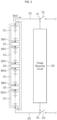
- FIG. 2 is a diagram for explaining voltage measurement of a battery apparatus according to an embodiment
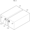
- FIG. 3 is a diagram showing an example of a bus-bar in a battery apparatus according to an embodiment.
- a plurality of battery modules 211, 212, 213, and 214 are connected in series in a battery pack 210. Although four battery modules 211, 212, 213, and 214 are shown in FIG. 2 for convenience of description, the number of battery modules is not limited thereto.
- a bus-bar 221 connects the battery module 211 and the battery module 212
- a bus-bar 222 connects the battery module 212 and the battery module 213
- a bus-bar 223 connects the battery module 213 and the battery module 214.
- a first terminal of the bus-bar 221 may be connected to a node BBP1 corresponding to a negative terminal of the battery module 211
- a second terminal of the bus-bar 221 may be connected to a node BBN1 corresponding to a positive terminal of the battery module 212.
- a first terminal of the bus-bar 222 may be connected to a node BBP2 corresponding to a negative terminal of the battery module 212, and a second terminal of the bus-bar 222 may be connected to a node BBN2 corresponding to a positive terminal of the battery module 213. Furthermore, a first terminal of the bus-bar 223 may be connected to a node BBP3 corresponding to a negative terminal of the battery module 213, and a second terminal of the bus-bar 223 may be connected to a node BBN3 corresponding to a positive terminal of the battery module 214.
- the positive terminal of each battery module may be connected to a positive electrode of the first battery cell among a plurality of battery cells, which are included in the corresponding battery module and are connected in series
- the negative terminal of each battery module may be connected to a negative electrode of the last battery cell among the plurality of battery cells, which are included in the corresponding battery module and are connected in series.
- the bus-bars 221, 222, and 223 may be formed of a material having electrical conductivity.
- the bus-bars 221, 222, and 223 may be formed in various shapes according to a structure of the battery pack 210 or the battery modules 211, 212, 213 and 214.
- the bus-bar 221 may be connected with an electrode terminal 211a of one battery module 211 and an electrode terminal 212a of the other battery module 212 so as to connect the battery module 211 and the battery module 212.
- the electrode terminal 211a of the battery module 211 may be a negative terminal of the battery module 211
- the electrode terminal 212a of the battery module 212 may be a positive terminal of the battery module 212.
- a current supplied from the battery apparatus may be interrupted when the connection is broken due to a defect in the connection status of the bus-bar.
- the positive terminal PV(+) of the battery pack 210 is connected to a positive main switch 241 through a wire 231, and the negative terminal PV(-) of the battery pack 210 is connected to a negative main switch 242 through a wire 232.
- the wire 231 may be connected to the positive main switch 241 at a node W1
- the wire 232 may be connected to the negative main switch 242 at a node W2.
- the positive terminal PV(+) of the battery pack 210 may correspond to a positive terminal of the first battery module 211 among the plurality of battery modules 211, 212, 213, and 214 included in the battery pack 210
- the negative terminal PV(-) of the battery pack 210 may correspond to a negative terminal of the last battery module 214 among the plurality of battery modules 211, 212, 213 and 214 included in the battery pack 210
- the wires 231 and 232 may be provided as a wire harness.
- a current I pack flows through the battery pack 210. That is, the current I pack flows through the plurality of battery modules 211, 212, 213, and 214.
- a voltage measuring circuit 250 measures voltages of the bus-bars 221, 222, and 223.
- the voltage measuring circuit 250 may measure a voltage between the first terminal and the second terminal of each bus-bar as the voltage of the corresponding bus-bar.
- the voltage measuring circuit 250 may measure a voltage between the both terminals of the bus-bar 221, i.e., a voltage between the two nodes BBP1 and BBN1, as a voltage of the bus-bar 221, measure a voltage between the both terminals of the bus-bar 222, i.e., a voltage between the two nodes BBP2 and BBN2, as a voltage of the bus-bar 222, and measure a voltage between the both terminals of the bus-bar 223, i.e., a voltage between the two nodes BBP3 and BBN3, as a voltage of the bus-bar 223.
- the voltage measuring circuit 250 may include a cell voltage monitoring integrated circuit (IC).
- IC cell voltage monitoring integrated circuit
- a plurality of cell voltage monitoring ICs respectively corresponding to a plurality of battery modules may be provided.
- one cell voltage monitoring IC may correspond to at least two battery modules among the plurality of battery modules.
- one of the plurality of battery modules may correspond to two cell voltage monitoring ICs.
- one of the cell voltage monitoring ICs may correspond to some battery cells of the corresponding battery module, and the other one of the cell voltage monitoring ICs may correspond to the remaining battery cells of the corresponding battery module.
- the cell voltage monitoring IC may include a plurality of pins respectively connected to a plurality of battery cells of the battery module and two pins respectively connected to both terminals of the bus-bar. In this case, the cell voltage monitoring IC may measure the voltage of the bus-bar through the two pins respectively connected to both terminals of the bus-bar. Further, the cell voltage monitoring IC may measure a voltage of the battery cell through pins connected to the positive and negative electrodes of the battery cell.
- the processor (e.g., 150 in FIG. 1 ) may diagnose connection statuses of the bus-bars 221, 222, and 223 based on the voltages measured by the voltage measuring circuit 250.
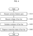
- FIG. 4 is a flowchart showing a method for diagnosing a connection status in a battery apparatus according to an embodiment.
- a processor e.g., 150 in FIG. 1
- a battery management system closes a positive main switch (e.g., 141 in FIG. 2 ) and a negative main switch (e.g., FIG. 142 in FIG. 2 ).
- a current flows through the battery pack (e.g., 210 in FIG. 2 ).
- the processor 150 receives a current of the battery pack measured by a current sensor at S410.
- a voltage measuring circuit 250 measures a voltage of a bus-bar (e.g., 221, 222, or 223 in FIG. 2 ) connecting adjacent battery modules at S420.
- the voltage measuring circuit 250 may measure a voltage between both terminals of the bus-bar 221, 222, or 223 as the voltage of the bus-bar 221, 222, or 223.
- the processor 150 receives the voltages of the bus-bars 221, 222, and 223 from the voltage measuring circuit 250 at S420.
- the processor 150 calculates a resistance of each of the bus-bars 221, 222, and 223 based on the current of the battery pack 210 and the voltage of each of the bus-bars 221, 222, and 223 at S430.
- the voltage measuring circuit 250 may determine, as the resistance of each of the bus-bars 221, 222, and 223, a value obtained by dividing the voltage of each of the bus-bars 221, 222, and 223 by the current of the battery pack 210, as in Equation 1.
- R busbar V busbar I pack
- Equation 1 R busbar denotes the resistance of the busbar, V busbar denotes the voltage of the busbar, and I pack denotes the current of the battery pack.
- the processor 150 diagnoses a connection status of the battery apparatus based on the resistance of each bus-bar and a resistance of a wire at S440. In some embodiments, the processor 150 may determine whether the resistance of each bus-bar is greater than a threshold, and if there is a bus-bar having the resistance greater than the threshold, the processor 150 may diagnose that an error has occurred in the connection status of the corresponding bus-bar. In some embodiments, when diagnosing that the error has occurred in the connection status of the bus-bar, the processor 150 may transmit an error signal to an external apparatus (e.g., a vehicle). Accordingly, a user (e.g., a driver) of the external apparatus may check the error and perform an action corresponding to the error.
- an external apparatus e.g., a vehicle
- an error may occur not only in the connection of the bus-bar, but also in a connection status of wires 231 and 232 connecting the battery pack 210 and the main switches 241 and 242. Accordingly, it may not be possible to accurately diagnose the connection status of the battery apparatus only by diagnosing the connection status of the bus-bar.
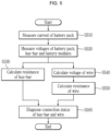
- FIG. 5 is a flowchart showing a method for diagnosing a connection status in a battery apparatus according to another embodiment.
- a processor (e.g., 150 in FIG. 1 ) of the battery management system closes a positive main switch (e.g., 141 in FIG. 2 ) and a negative switch (e.g., FIG. 142 in FIG. 2 ). Then, a current flows through a battery pack (e.g., 210 in FIG. 2 ). Accordingly, the processor 150 receives a current of the battery pack measured by a current sensor at S510.
- a voltage measuring circuit measures a voltage of a bus-bar (e.g., 221, 222, or 223 in FIG. 2 ) connecting adjacent battery modules.
- the voltage measuring circuit 250 may measure a voltage between both terminals of the bus-bar 221, 222, or 223 as the voltage of the bus-bar 221, 222, or 223.
- the processor 150 receives the voltages of the bus-bars 221, 222, and 223 from the voltage measuring circuit 250 at S520.
- the voltage measuring circuit 250 measures a voltage of the battery pack 210 and voltages of battery modules (e.g., 211, 212, 213, and 214 in FIG. 2 ) at S520.
- the voltage measuring circuit 250 may measure the voltage of the battery pack 210 by measuring voltages of nodes at which wires (e.g., 231 and 232 in FIG. 2 ) of the battery pack 210 are connected to the main switches (e.g., 241 and 242 in FIG. 2 ).
- the voltage measuring circuit 250 may measure a voltage between a positive terminal and a negative terminal of each battery module as the voltage of the corresponding battery module.
- the voltage measuring circuit 250 may measure the voltage of each battery module as a sum of voltages of a plurality of battery cells included in the corresponding battery module.
- the processor 150 receives the voltage of the battery pack 210 and the voltages of the battery modules from the voltage measuring circuit 250 at S520.
- the processor 150 calculates a resistance of each of the bus-bars 221, 222, and 223 based on the current of the battery pack 210 and the voltage of each of the bus-bars 221, 222, and 223 at S530. In some embodiments, the processor 150 may calculate the resistance of each of the bus-bars 221, 222, and 223 as described with reference to S430 of FIG. 4 .
- the processor 150 calculates a voltage across the wires 231 and 232 based on the current of the battery pack 210, the voltage of the battery pack 210, and the voltages of the battery modules 211, 212, 213 and 214 at S540.
- the voltage measuring circuit 250 may measure the voltage of the battery pack 210 by measuring a voltage of a node (e.g., W1 in FIG. 2 ) at which the wire 231 is connected to the positive main switch 241 and a voltage of a node (e.g., W2 in FIG. 2 ) at which the wire 232 is connected to the negative main switch 242.
- the voltage measuring circuit 250 may measure a voltage between the two nodes W1 and W2 as the voltage of the battery pack 210.
- the voltage of the battery pack 210 i.e., the voltage between the two nodes W1 and W2 is formed by the voltage across the wires 231 and 232, the voltages of the battery module 211, 212, 213, and 214, and the voltages of the bus-bars 221, 222, and 223, the processor 150 may determine, as the voltage across the two wires 231 and 232, a value obtained by subtracting the voltages of the battery modules 211, 212, 213, and 214, and the voltages of the bus-bars 221, 222, and 223 from the voltage of the battery pack 210, as in Equation 2.
- V module i ⁇ ⁇ i 1 M
- V wire denotes the voltage across the two wires
- V pack denotes the voltage of the battery pack
- V module (i) denotes the voltage of the i-th battery module
- N denotes the number of battery modules included in the battery pack
- V busbar (i) denotes the voltage of the i-th bus-bar
- M denotes the number of bus-bars included in the battery pack. In some embodiments, M may be equal to (N-1).
- the processor 150 calculates a resistance of the wires 231 and 232 based on the current of the battery pack 210 and the voltage across the wires 231 and 232 at S550.
- the voltage measuring circuit 250 may determine, as the resistance of the two wires 231 and 232, a value obtained by dividing the voltage across the wires 231 and 232 by the current of the battery pack 210.
- R wire V wire I pack
- Equation 3 R wire denotes the resistance of the two wires, V wire denotes the voltage across the two wires, and I pack denotes the current of the battery pack.
- the processor 150 diagnoses a connection status of the battery apparatus based on the resistance of each bus-bar and the resistance of the wires at S560. In some embodiments, the processor 150 may determine whether the resistance of each bus-bar is greater than a threshold, and if there is a bus-bar having the resistance greater than the threshold, the processor 150 may diagnose that an error has occurred in the connection status of the corresponding bus-bar. Further, the processor 150 may determine whether the resistance of the wires is greater than a threshold, and if the resistance of the wires is greater than the threshold value, the processor 150 may diagnose that an error has occurred in the connection status of the wires.
- the processor 150 may transmit an error signal to an external apparatus (e.g., a vehicle). Accordingly, a user (e.g., a driver) of the external apparatus may check the error and perform an action corresponding to the error.
- an external apparatus e.g., a vehicle
- connection status of the bus-bar not only the connection status of the bus-bar but also the connection status of the wires connecting the battery pack to the main switches can be diagnosed, so that the connection status of the battery apparatus can be accurately diagnosed.
Landscapes
- Engineering & Computer Science (AREA)
- General Physics & Mathematics (AREA)
- Physics & Mathematics (AREA)
- Chemical Kinetics & Catalysis (AREA)
- Chemical & Material Sciences (AREA)
- Electrochemistry (AREA)
- General Chemical & Material Sciences (AREA)
- Manufacturing & Machinery (AREA)
- Power Engineering (AREA)
- Sustainable Development (AREA)
- Life Sciences & Earth Sciences (AREA)
- Sustainable Energy (AREA)
- Transportation (AREA)
- Mechanical Engineering (AREA)
- Microelectronics & Electronic Packaging (AREA)
- Secondary Cells (AREA)
- Connection Of Batteries Or Terminals (AREA)
- Battery Mounting, Suspending (AREA)
- Charge And Discharge Circuits For Batteries Or The Like (AREA)
Claims (15)
- Batterievorrichtung (100) umfassend:einen Batteriepack (110, 210), umfassend eine Mehrzahl von Batteriemodulen (211, 212, 213, 214) und eine Sammelschiene (221, 222, 223), welche zwei Batteriemodule unter der Mehrzahl von Batteriemodulen (211, 212, 213, 214) verbindet;einen Schalter (121, 122, 241, 242), welcher dazu eingerichtet ist, eine Stromversorgung des Batteriepacks (110, 210) zu steuern;eine Leitung (231, 232), welche den Batteriepack (110, 210) und den Schalter (121, 122, 241, 242) verbindet;eine Spannungsmessschaltung (130), welche dazu eingerichtet ist, eine Spannung der Sammelschiene (221, 222, 223), eine Spannung des Batteriepacks (110, 210) und Spannungen der Mehrzahl von Batteriemodulen (211, 212, 213, 214) zu messen; undeinen Prozessor (150), welcher dazu eingerichtet ist, einen Verbindungsstatus der Sammelschiene (221, 222, 223) und einen Verbindungsstatus der Leitung (231, 232) zu erkennen, auf Grundlage eines Stroms des Batteriepacks (110, 210), der Spannung der Sammelschiene (221, 222, 223), der Spannung des Batteriepacks (110, 210) und der Spannungen der Mehrzahl von Batteriemodulen (211, 212, 213, 214).
- Batterievorrichtung (100) nach Anspruch 1, wobei der Prozessor (150) dazu eingerichtet ist:einen Widerstand der Sammelschiene (221, 222, 223) zu berechnen, auf Grundlage der Spannung der Sammelschiene (221, 222, 223) und des Stroms des Batteriepacks (110, 210); undden Verbindungsstatus der Sammelschiene (221, 222, 223) zu erkennen, auf Grundlage des Widerstands der Sammelschiene (221, 222, 223).
- Batterievorrichtung (100) nach Anspruch 2, wobei der Prozessor (150) dazu eingerichtet ist, zu erkennen, dass ein Fehler in dem Verbindungsstatus der Sammelschiene (221, 222, 223) aufgetreten ist, in Reaktion darauf, dass der Widerstand der Sammelschiene (221, 222, 223) größer als ein Schwellenwert ist.
- Batterievorrichtung (100) nach Anspruch 1, wobei der Prozessor (150) dazu eingerichtet ist, die Spannung der Sammelschiene (221, 222, 223) zu bestimmen, auf Grundlage einer Spannung zwischen einem Knoten, bei welchem die Sammelschiene (221, 222, 223) mit einem der zwei Batteriemodule verbunden ist und einem Knoten, bei welchem die Sammelschiene (221, 222, 223) mit dem anderen der zwei Batteriemodule verbunden ist.
- Batterievorrichtung (100) nach Anspruch 1, wobei der Prozessor (150) dazu eingerichtet ist:eine Spannung über der Leitung (231, 232) zu bestimmen, auf Grundlage der Spannung der Sammelschiene (221, 222, 223), der Spannung des Batteriepacks (110, 210) und der Spannungen der Mehrzahl von Batteriemodulen,einen Widerstand der Leitung zu berechnen, auf Grundlage der Spannung über der Leitung und des Stroms des Batteriepacks (110, 210); undden Verbindungsstatus der Leitung zu erkennen, auf Grundlage des Widerstands der Leitung.
- Batterievorrichtung (100) nach Anspruch 5, wobei der Prozessor (150) dazu eingerichtet ist, zu erkennen, dass ein Fehler in dem Verbindungsstatus der Leitung (231, 232) aufgetreten ist, in Reaktion darauf, dass der Widerstand der Leitung größer als ein Schwellenwert ist.
- Batterievorrichtung (100) nach Anspruch 5, wobei der Schalter einen ersten Schalter (241) und einen zweiten Schalter (242) umfasst,wobei die Leitung eine erste Leitung (231), welche einen positiven Anschluss des Batteriepacks (110, 210) und den ersten Schalter (241) verbindet, und eine zweite Leitung (232) umfasst, welche einen negativen Anschluss des Batteriepacks (110, 210) und den zweiten Schalter (242) verbindet, undwobei die Spannung über der Leitung eine Spannung über der ersten Leitung (231) und eine Spannung über der zweiten Leitung (232) umfasst.
- Batterievorrichtung (100) nach Anspruch 7, wobei die Spannungsmessschaltung dazu eingerichtet ist, die Spannung des Batteriepacks (110, 210) zu messen, auf Grundlage einer Spannung zwischen einem ersten Knoten (W1), an welchem die erste Leitung (231) mit dem ersten Schalter (241) verbunden ist, und einem zweiten Knoten (W2), an welchem die zweite Leitung (232) mit dem zweiten Schalter (242) verbunden ist.
- Batterievorrichtung (100) nach Anspruch 5, wobei der Prozessor (150) dazu eingerichtet ist, die Spannung über der Leitung (231, 232) zu bestimmen, auf Grundlage eines Werts, welcher durch ein Subtrahieren einer Summe der Spannungen der Mehrzahl von Batteriemodulen und der Spannung der Sammelschiene (221, 222, 223) von der Spannung des Batteriepacks (110, 210) erhalten ist.
- Batterievorrichtung (100) nach Anspruch 9, wobei die Sammelschiene (221, 222, 223) eine Mehrzahl von Sammelschienen (221, 222, 223) umfasst, und jede der Sammelschienen jeweilige zwei Batteriemodule unter der Mehrzahl von Batteriemodulen (211, 212, 213, 214) verbindet, und
wobei der Prozessor (150) dazu eingerichtet ist, die Spannung über der Leitung (231, 232) zu bestimmen, auf Grundlage eines Werts, welcher durch ein Subtrahieren einer Summe der Spannungen der Mehrzahl von Batteriemodulen (211, 212, 213, 214) und einer Summe von Spannungen der Mehrzahl von Sammelschienen (221, 222, 223) von der Spannung des Batteriepacks (110, 210) erhalten ist. - Verfahren eines Erkennens eines Verbindungsstatus eines Batteriepacks (110, 120), umfassend eine Mehrzahl von Batteriemodulen, wobei das Verfahren umfasst:ein Messen (S410) eines Stroms des Batteriepacks (110, 210);ein Messen einer Spannung des Batteriepacks (110, 210);ein Messen einer Spannung von jedem der Mehrzahl von Batteriemodulen (211, 212, 213, 214);ein Messen (S420) einer Spannung einer Sammelschiene (221, 222, 223), welche zwei Batteriemodule unter der Mehrzahl von Batteriemodulen (211, 212, 213, 214) verbindet; undein Erkennen (S440) eines Verbindungsstatus der Sammelschiene (221, 222, 223) und eines Verbindungsstatus einer Leitung, welche mit dem Batteriepack (110, 210) verbunden ist, auf Grundlage des Stroms des Batteriepacks (210, 110), der Spannung der Sammelschiene (221, 222, 223), der Spannung des Batteriepacks (110, 210) und Spannungen der Mehrzahl von Batteriemodulen (211, 212, 213, 214).
- Verfahren nach Anspruch 11, wobei das Erkennen des Verbindungsstatus umfasst:ein Berechnen eines Widerstands der Sammelschiene (221, 222, 223), auf Grundlage der Spannung der Sammelschiene und des Stroms des Batteriepacks (110, 210); undein Erkennen (S440) des Verbindungsstatus der Sammelschiene (221, 222, 223), auf Grundlage des Widerstands der Sammelschiene (221, 222, 223).
- Verfahren nach Anspruch 11, wobei das Erkennen des Verbindungsstatus umfasst:ein Bestimmen einer Spannung entlang der Leitung, auf Grundlage der Spannung der Sammelschiene (221, 222, 223), der Spannung des Batteriepacks (110, 210) und der Spannung der Mehrzahl von Batteriemodulen (211, 212, 213, 214);ein Berechnen (S430) eines Widerstands der Leitung, auf Grundlage der Spannung über der Leitung und des Stroms des Batteriepacks (110, 210); undein Erkennen (S440) des Verbindungsstatus der Leitung (231, 232), auf Grundlage des Widerstands der Leitung (231, 232).
- Verfahren nach Anspruch 11, wobei die Leitung (231, 232) eine erste Leitung (231), welche einen positiven Anschluss des Batteriepacks (110, 210) und einen ersten Schalter (241) für ein Steuern einer Stromversorgung des Batteriepacks (110, 210) verbindet, und eine zweite Leitung (232) umfasst, welche einen negativen Anschluss des Batteriepacks (110, 210) und einen zweiten Schalter (242) für ein Steuern einer Stromversorgung des Batteriepacks (110, 210) verbindet, und
wobei das Messen der Spannung des Batteriepacks (110, 210) ein Messen der Spannung des Batteriepacks (110, 210) umfasst, auf Grundlage einer Spannung zwischen einem ersten Knoten (W1), an welchem die erste Leitung (231) mit dem ersten Schalter (241) verbunden ist, und einem zweiten Knoten (W2), an welchem die zweite Leitung (232) mit dem zweiten Schalter (242) verbunden ist. - Batterie-Management-System, umfassend die Batterievorrichtung (100) nach einem der Ansprüche 1 bis 10.
Priority Applications (1)
| Application Number | Priority Date | Filing Date | Title |
|---|---|---|---|
| EP25183428.9A EP4629431A3 (de) | 2020-10-12 | 2021-09-23 | Batterievorrichtung, batterieverwaltungssystem und verfahren zur diagnose des verbindungsstatus |
Applications Claiming Priority (2)
| Application Number | Priority Date | Filing Date | Title |
|---|---|---|---|
| KR1020200131092A KR102807492B1 (ko) | 2020-10-12 | 2020-10-12 | 배터리 장치, 배터리 관리 시스템 및 연결 상태 진단 방법 |
| PCT/KR2021/012928 WO2022080692A1 (ko) | 2020-10-12 | 2021-09-23 | 배터리 장치, 배터리 관리 시스템 및 연결 상태 진단 방법 |
Related Child Applications (1)
| Application Number | Title | Priority Date | Filing Date |
|---|---|---|---|
| EP25183428.9A Division EP4629431A3 (de) | 2020-10-12 | 2021-09-23 | Batterievorrichtung, batterieverwaltungssystem und verfahren zur diagnose des verbindungsstatus |
Publications (3)
| Publication Number | Publication Date |
|---|---|
| EP4067922A1 EP4067922A1 (de) | 2022-10-05 |
| EP4067922A4 EP4067922A4 (de) | 2023-06-28 |
| EP4067922B1 true EP4067922B1 (de) | 2025-06-18 |
Family
ID=81208337
Family Applications (2)
| Application Number | Title | Priority Date | Filing Date |
|---|---|---|---|
| EP21880340.1A Active EP4067922B1 (de) | 2020-10-12 | 2021-09-23 | Batterievorrichtung, batterieverwaltungssystem und verfahren zum diagnostizieren des verbindungszustands |
| EP25183428.9A Pending EP4629431A3 (de) | 2020-10-12 | 2021-09-23 | Batterievorrichtung, batterieverwaltungssystem und verfahren zur diagnose des verbindungsstatus |
Family Applications After (1)
| Application Number | Title | Priority Date | Filing Date |
|---|---|---|---|
| EP25183428.9A Pending EP4629431A3 (de) | 2020-10-12 | 2021-09-23 | Batterievorrichtung, batterieverwaltungssystem und verfahren zur diagnose des verbindungsstatus |
Country Status (8)
| Country | Link |
|---|---|
| US (1) | US12374731B2 (de) |
| EP (2) | EP4067922B1 (de) |
| JP (1) | JP7351494B2 (de) |
| KR (1) | KR102807492B1 (de) |
| CN (1) | CN115004049A (de) |
| ES (1) | ES3035705T3 (de) |
| HU (1) | HUE072030T2 (de) |
| WO (1) | WO2022080692A1 (de) |
Families Citing this family (10)
| Publication number | Priority date | Publication date | Assignee | Title |
|---|---|---|---|---|
| KR102920622B1 (ko) * | 2021-11-04 | 2026-01-29 | 주식회사 엘지에너지솔루션 | 복수의 배터리 뱅크 관리 방법 및 이를 적용한 배터리 시스템 |
| WO2023120186A1 (ja) * | 2021-12-23 | 2023-06-29 | パナソニックIpマネジメント株式会社 | 電池状態分析システム、電池状態分析方法、および電池状態分析プログラム |
| US12306255B2 (en) * | 2022-03-31 | 2025-05-20 | Ablic Inc. | Battery voltage monitoring device |
| KR102609874B1 (ko) * | 2022-12-02 | 2023-12-05 | 한국생산기술연구원 | 저항인자를 활용한 배터리 팩 시스템의 고장 진단방법 |
| KR20240124673A (ko) * | 2023-02-09 | 2024-08-19 | 주식회사 엘지에너지솔루션 | 배터리 관리 장치, 서버 및 이들을 포함하는 배터리 시스템 |
| KR102650615B1 (ko) * | 2023-10-11 | 2024-03-25 | 한국생산기술연구원 | 전기자동차 배터리 시스템의 연결부 내부저항 측정 및 열화진단방법 |
| SE547393C2 (en) * | 2023-11-24 | 2025-09-09 | Scania Cv Ab | A method and control arrangement for diagnosing an electric battery unit |
| KR102903617B1 (ko) * | 2023-12-18 | 2025-12-23 | 모나 주식회사 | 배터리 모듈의 용접 결함 검사장치 |
| KR102851940B1 (ko) * | 2024-02-01 | 2025-08-28 | 경북대학교 산학협력단 | 배터리 진단시스템 및 배터리 진단방법 |
| EP4675286A1 (de) * | 2024-07-05 | 2026-01-07 | Volvo Truck Corporation | Verfahren und computersystem zur diagnose einer elektrischen verbindung in einem stromspeicherpack |
Family Cites Families (21)
| Publication number | Priority date | Publication date | Assignee | Title |
|---|---|---|---|---|
| JP5272978B2 (ja) | 2009-09-02 | 2013-08-28 | 三菱自動車工業株式会社 | バッテリ装置 |
| JP5508180B2 (ja) | 2010-08-02 | 2014-05-28 | 日立ビークルエナジー株式会社 | 蓄電装置、蓄電装置の充放電方法、蓄電装置の運転方法および車両 |
| KR101189582B1 (ko) | 2010-12-01 | 2012-10-11 | 기아자동차주식회사 | 배터리 전압 측정 라인의 단선 검출용 전압 측정 장치 |
| KR101310733B1 (ko) | 2011-01-07 | 2013-09-24 | 주식회사 엘지화학 | 배터리 팩 관리 장치 및 방법 |
| JP5230789B2 (ja) * | 2011-11-25 | 2013-07-10 | 三菱重工業株式会社 | 電池システム |
| KR101889558B1 (ko) * | 2011-12-15 | 2018-08-21 | 현대모비스 주식회사 | 이차전지 배터리의 단선검출장치 |
| CN103308860A (zh) * | 2012-03-15 | 2013-09-18 | 凹凸电子(武汉)有限公司 | 电池故障检测方法、电池故障检测装置及电池管理系统 |
| KR20140055065A (ko) * | 2012-10-30 | 2014-05-09 | 주식회사 엘지화학 | 배터리 팩 관리 장치 및 방법 |
| JP6155854B2 (ja) | 2013-05-31 | 2017-07-05 | 株式会社デンソー | 電池システム |
| JP6442822B2 (ja) | 2013-10-01 | 2018-12-26 | 株式会社Gsユアサ | 異常判定装置 |
| JP6097678B2 (ja) * | 2013-12-18 | 2017-03-15 | 株式会社富士通テレコムネットワークス福島 | 接触不良を検出する充放電試験装置 |
| KR101655377B1 (ko) | 2014-12-05 | 2016-09-07 | 현대오트론 주식회사 | 배터리 버스바의 고장 진단 장치 및 방법 |
| JP6361502B2 (ja) * | 2014-12-26 | 2018-07-25 | トヨタ自動車株式会社 | 電池監視装置 |
| KR20160123173A (ko) * | 2015-04-15 | 2016-10-25 | 삼성전자주식회사 | 부스바의 연결 상태 판단 장치 및 방법 |
| WO2017072949A1 (ja) | 2015-10-30 | 2017-05-04 | 株式会社東芝 | 配線診断装置、電池システム、および電力システム |
| JP2018021880A (ja) | 2016-08-05 | 2018-02-08 | 株式会社デンソーテン | 電圧監視装置および組電池監視システム |
| CN107867186B (zh) * | 2016-09-27 | 2021-02-23 | 华为技术有限公司 | 电动汽车以及电动汽车之间充电的方法 |
| KR102398245B1 (ko) * | 2017-02-06 | 2022-05-13 | 에스케이온 주식회사 | 배터리 팩 및 상기 배터리 팩을 사용한 버스바 개방 여부 감지 방법 |
| KR102348105B1 (ko) * | 2018-01-15 | 2022-01-05 | 주식회사 엘지에너지솔루션 | 버스바의 고장을 진단하기 위한 배터리 관리 시스템 및 방법 |
| KR102627843B1 (ko) | 2018-09-10 | 2024-01-19 | 주식회사 엘지에너지솔루션 | 배터리 관리 장치 |
| US11712968B2 (en) * | 2019-12-18 | 2023-08-01 | Nio Technology (Anhui) Co., Ltd. | Method for detecting damage to battery pack enclosure during a crash event |
-
2020
- 2020-10-12 KR KR1020200131092A patent/KR102807492B1/ko active Active
-
2021
- 2021-09-23 WO PCT/KR2021/012928 patent/WO2022080692A1/ko not_active Ceased
- 2021-09-23 HU HUE21880340A patent/HUE072030T2/hu unknown
- 2021-09-23 EP EP21880340.1A patent/EP4067922B1/de active Active
- 2021-09-23 US US17/790,337 patent/US12374731B2/en active Active
- 2021-09-23 CN CN202180009296.1A patent/CN115004049A/zh active Pending
- 2021-09-23 EP EP25183428.9A patent/EP4629431A3/de active Pending
- 2021-09-23 JP JP2022537119A patent/JP7351494B2/ja active Active
- 2021-09-23 ES ES21880340T patent/ES3035705T3/es active Active
Also Published As
| Publication number | Publication date |
|---|---|
| JP7351494B2 (ja) | 2023-09-27 |
| KR102807492B1 (ko) | 2025-05-13 |
| HUE072030T2 (hu) | 2025-10-28 |
| EP4629431A3 (de) | 2026-01-14 |
| CN115004049A (zh) | 2022-09-02 |
| EP4067922A1 (de) | 2022-10-05 |
| KR20220048213A (ko) | 2022-04-19 |
| EP4067922A4 (de) | 2023-06-28 |
| ES3035705T3 (en) | 2025-09-08 |
| WO2022080692A1 (ko) | 2022-04-21 |
| US12374731B2 (en) | 2025-07-29 |
| EP4629431A2 (de) | 2025-10-08 |
| US20230039404A1 (en) | 2023-02-09 |
| JP2023507965A (ja) | 2023-02-28 |
Similar Documents
| Publication | Publication Date | Title |
|---|---|---|
| EP4067922B1 (de) | Batterievorrichtung, batterieverwaltungssystem und verfahren zum diagnostizieren des verbindungszustands | |
| EP3958006B1 (de) | Batteriediagnosevorrichtung und -verfahren | |
| EP3933415B1 (de) | Vorrichtung zur abschätzung des isolationswiderstandes und batteriesystem damit | |
| CN203166597U (zh) | 用于评估adc操作和电池组电压的系统 | |
| US12111365B2 (en) | Battery apparatus and method for measuring cell voltage | |
| US10333182B2 (en) | Estimation of cell voltage excursion in the presence of battery pack sensing faults | |
| KR20230109916A (ko) | 배터리 상태 추정 방법 및 그 방법을 제공하는 배터리 시스템 | |
| WO2007089047A1 (ja) | 二次電池の監視装置 | |
| EP4001937A1 (de) | Batterievorrichtung, batterieverwaltungssystem und verfahren zur diagnose der versorgungsspannung eines schützes | |
| US12026030B2 (en) | Battery apparatus, battery management system, and method for correcting measured voltage | |
| EP4102245B1 (de) | Batterievorrichtung und verfahren zur diagnose von stromsensoren | |
| EP4401272B1 (de) | Batterievorrichtung, batteriesystem und diagnoseverfahren | |
| KR102839450B1 (ko) | 배터리 장치 및 드리프트 오류 진단 방법 | |
| EP4404426B1 (de) | Batterieverwaltungssystem, verfahren zur konfiguration der vorladungsperiode und batterievorrichtung | |
| KR20210104458A (ko) | 배터리 장치 및 전류 센서 진단 방법 | |
| EP4386406A1 (de) | Batteriediagnoseverfahren und batteriediagnosevorrichtung sowie batteriesystem damit | |
| EP4700407A1 (de) | Batterieverwaltungssystem, batterievorrichtung und verfahren zur diagnose einer zellspannungsmessleitung | |
| KR20220036555A (ko) | 배터리 장치, 배터리 관리 시스템 및 프리차지 전류 측정 방법 | |
| EP4403944A1 (de) | Batterievorrichtung und batterieverwaltungssystem zur isolationswiderstandsmessung | |
| EP4261553A1 (de) | Batterieverwaltungsverfahren und batteriesystem damit | |
| US12584963B2 (en) | Stuck-closed diagnosis method and battery system using the same | |
| EP4246160B1 (de) | Batterieverwaltungsvorrichtung und -verfahren | |
| US20250291002A1 (en) | Abnormality detection system |
Legal Events
| Date | Code | Title | Description |
|---|---|---|---|
| STAA | Information on the status of an ep patent application or granted ep patent |
Free format text: STATUS: THE INTERNATIONAL PUBLICATION HAS BEEN MADE |
|
| PUAI | Public reference made under article 153(3) epc to a published international application that has entered the european phase |
Free format text: ORIGINAL CODE: 0009012 |
|
| STAA | Information on the status of an ep patent application or granted ep patent |
Free format text: STATUS: REQUEST FOR EXAMINATION WAS MADE |
|
| 17P | Request for examination filed |
Effective date: 20220701 |
|
| AK | Designated contracting states |
Kind code of ref document: A1 Designated state(s): AL AT BE BG CH CY CZ DE DK EE ES FI FR GB GR HR HU IE IS IT LI LT LU LV MC MK MT NL NO PL PT RO RS SE SI SK SM TR |
|
| A4 | Supplementary search report drawn up and despatched |
Effective date: 20230531 |
|
| RIC1 | Information provided on ipc code assigned before grant |
Ipc: B60L 58/21 20190101ALI20230524BHEP Ipc: B60L 50/64 20190101ALI20230524BHEP Ipc: B60L 3/00 20190101ALI20230524BHEP Ipc: H01M 50/502 20210101ALI20230524BHEP Ipc: H01M 10/48 20060101ALI20230524BHEP Ipc: G01R 31/396 20190101ALI20230524BHEP Ipc: G01R 31/385 20190101ALI20230524BHEP Ipc: G01R 27/08 20060101ALI20230524BHEP Ipc: G01R 31/389 20190101ALI20230524BHEP Ipc: G01R 31/3842 20190101ALI20230524BHEP Ipc: G01R 31/58 20200101ALI20230524BHEP Ipc: G01R 31/392 20190101ALI20230524BHEP Ipc: G01R 31/66 20200101AFI20230524BHEP |
|
| DAV | Request for validation of the european patent (deleted) | ||
| DAX | Request for extension of the european patent (deleted) | ||
| GRAP | Despatch of communication of intention to grant a patent |
Free format text: ORIGINAL CODE: EPIDOSNIGR1 |
|
| STAA | Information on the status of an ep patent application or granted ep patent |
Free format text: STATUS: GRANT OF PATENT IS INTENDED |
|
| RIC1 | Information provided on ipc code assigned before grant |
Ipc: H01M 50/569 20210101ALI20250204BHEP Ipc: H01M 50/204 20210101ALI20250204BHEP Ipc: H01M 10/42 20060101ALI20250204BHEP Ipc: B60L 58/21 20190101ALI20250204BHEP Ipc: B60L 50/64 20190101ALI20250204BHEP Ipc: B60L 3/00 20190101ALI20250204BHEP Ipc: H01M 50/502 20210101ALI20250204BHEP Ipc: H01M 10/48 20060101ALI20250204BHEP Ipc: G01R 31/396 20190101ALI20250204BHEP Ipc: G01R 31/385 20190101ALI20250204BHEP Ipc: G01R 27/08 20060101ALI20250204BHEP Ipc: G01R 31/389 20190101ALI20250204BHEP Ipc: G01R 31/3842 20190101ALI20250204BHEP Ipc: G01R 31/58 20200101ALI20250204BHEP Ipc: G01R 31/392 20190101ALI20250204BHEP Ipc: G01R 31/66 20200101AFI20250204BHEP |
|
| INTG | Intention to grant announced |
Effective date: 20250220 |
|
| P01 | Opt-out of the competence of the unified patent court (upc) registered |
Free format text: CASE NUMBER: APP_13959/2025 Effective date: 20250321 |
|
| GRAS | Grant fee paid |
Free format text: ORIGINAL CODE: EPIDOSNIGR3 |
|
| GRAA | (expected) grant |
Free format text: ORIGINAL CODE: 0009210 |
|
| STAA | Information on the status of an ep patent application or granted ep patent |
Free format text: STATUS: THE PATENT HAS BEEN GRANTED |
|
| AK | Designated contracting states |
Kind code of ref document: B1 Designated state(s): AL AT BE BG CH CY CZ DE DK EE ES FI FR GB GR HR HU IE IS IT LI LT LU LV MC MK MT NL NO PL PT RO RS SE SI SK SM TR |
|
| REG | Reference to a national code |
Ref country code: GB Ref legal event code: FG4D |
|
| REG | Reference to a national code |
Ref country code: CH Ref legal event code: EP |
|
| REG | Reference to a national code |
Ref country code: DE Ref legal event code: R096 Ref document number: 602021032604 Country of ref document: DE |
|
| REG | Reference to a national code |
Ref country code: CH Ref legal event code: EP |
|
| REG | Reference to a national code |
Ref country code: IE Ref legal event code: FG4D |
|
| REG | Reference to a national code |
Ref country code: ES Ref legal event code: FG2A Ref document number: 3035705 Country of ref document: ES Kind code of ref document: T3 Effective date: 20250908 |
|
| PG25 | Lapsed in a contracting state [announced via postgrant information from national office to epo] |
Ref country code: FI Free format text: LAPSE BECAUSE OF FAILURE TO SUBMIT A TRANSLATION OF THE DESCRIPTION OR TO PAY THE FEE WITHIN THE PRESCRIBED TIME-LIMIT Effective date: 20250618 |
|
| PGFP | Annual fee paid to national office [announced via postgrant information from national office to epo] |
Ref country code: DE Payment date: 20250820 Year of fee payment: 5 |
|
| REG | Reference to a national code |
Ref country code: LT Ref legal event code: MG9D |
|
| PG25 | Lapsed in a contracting state [announced via postgrant information from national office to epo] |
Ref country code: NO Free format text: LAPSE BECAUSE OF FAILURE TO SUBMIT A TRANSLATION OF THE DESCRIPTION OR TO PAY THE FEE WITHIN THE PRESCRIBED TIME-LIMIT Effective date: 20250918 Ref country code: GR Free format text: LAPSE BECAUSE OF FAILURE TO SUBMIT A TRANSLATION OF THE DESCRIPTION OR TO PAY THE FEE WITHIN THE PRESCRIBED TIME-LIMIT Effective date: 20250919 |
|
| PG25 | Lapsed in a contracting state [announced via postgrant information from national office to epo] |
Ref country code: BG Free format text: LAPSE BECAUSE OF FAILURE TO SUBMIT A TRANSLATION OF THE DESCRIPTION OR TO PAY THE FEE WITHIN THE PRESCRIBED TIME-LIMIT Effective date: 20250618 |
|
| PGFP | Annual fee paid to national office [announced via postgrant information from national office to epo] |
Ref country code: HU Payment date: 20250929 Year of fee payment: 5 Ref country code: BE Payment date: 20250820 Year of fee payment: 5 Ref country code: GB Payment date: 20250820 Year of fee payment: 5 |
|
| PG25 | Lapsed in a contracting state [announced via postgrant information from national office to epo] |
Ref country code: HR Free format text: LAPSE BECAUSE OF FAILURE TO SUBMIT A TRANSLATION OF THE DESCRIPTION OR TO PAY THE FEE WITHIN THE PRESCRIBED TIME-LIMIT Effective date: 20250618 |
|
| PGFP | Annual fee paid to national office [announced via postgrant information from national office to epo] |
Ref country code: AT Payment date: 20251020 Year of fee payment: 5 Ref country code: FR Payment date: 20250821 Year of fee payment: 5 |
|
| PG25 | Lapsed in a contracting state [announced via postgrant information from national office to epo] |
Ref country code: RS Free format text: LAPSE BECAUSE OF FAILURE TO SUBMIT A TRANSLATION OF THE DESCRIPTION OR TO PAY THE FEE WITHIN THE PRESCRIBED TIME-LIMIT Effective date: 20250918 |
|
| REG | Reference to a national code |
Ref country code: NL Ref legal event code: MP Effective date: 20250618 |
|
| REG | Reference to a national code |
Ref country code: HU Ref legal event code: AG4A Ref document number: E072030 Country of ref document: HU |
|
| PG25 | Lapsed in a contracting state [announced via postgrant information from national office to epo] |
Ref country code: LV Free format text: LAPSE BECAUSE OF FAILURE TO SUBMIT A TRANSLATION OF THE DESCRIPTION OR TO PAY THE FEE WITHIN THE PRESCRIBED TIME-LIMIT Effective date: 20250618 |
|
| PG25 | Lapsed in a contracting state [announced via postgrant information from national office to epo] |
Ref country code: NL Free format text: LAPSE BECAUSE OF FAILURE TO SUBMIT A TRANSLATION OF THE DESCRIPTION OR TO PAY THE FEE WITHIN THE PRESCRIBED TIME-LIMIT Effective date: 20250618 |
|
| PG25 | Lapsed in a contracting state [announced via postgrant information from national office to epo] |
Ref country code: PT Free format text: LAPSE BECAUSE OF FAILURE TO SUBMIT A TRANSLATION OF THE DESCRIPTION OR TO PAY THE FEE WITHIN THE PRESCRIBED TIME-LIMIT Effective date: 20251020 |
|
| REG | Reference to a national code |
Ref country code: AT Ref legal event code: MK05 Ref document number: 1804655 Country of ref document: AT Kind code of ref document: T Effective date: 20250618 |
|
| PG25 | Lapsed in a contracting state [announced via postgrant information from national office to epo] |
Ref country code: IS Free format text: LAPSE BECAUSE OF FAILURE TO SUBMIT A TRANSLATION OF THE DESCRIPTION OR TO PAY THE FEE WITHIN THE PRESCRIBED TIME-LIMIT Effective date: 20251018 |
|
| PG25 | Lapsed in a contracting state [announced via postgrant information from national office to epo] |
Ref country code: AT Free format text: LAPSE BECAUSE OF FAILURE TO SUBMIT A TRANSLATION OF THE DESCRIPTION OR TO PAY THE FEE WITHIN THE PRESCRIBED TIME-LIMIT Effective date: 20250618 Ref country code: SM Free format text: LAPSE BECAUSE OF FAILURE TO SUBMIT A TRANSLATION OF THE DESCRIPTION OR TO PAY THE FEE WITHIN THE PRESCRIBED TIME-LIMIT Effective date: 20250618 |
|
| PG25 | Lapsed in a contracting state [announced via postgrant information from national office to epo] |
Ref country code: CZ Free format text: LAPSE BECAUSE OF FAILURE TO SUBMIT A TRANSLATION OF THE DESCRIPTION OR TO PAY THE FEE WITHIN THE PRESCRIBED TIME-LIMIT Effective date: 20250618 |
|
| PG25 | Lapsed in a contracting state [announced via postgrant information from national office to epo] |
Ref country code: PL Free format text: LAPSE BECAUSE OF FAILURE TO SUBMIT A TRANSLATION OF THE DESCRIPTION OR TO PAY THE FEE WITHIN THE PRESCRIBED TIME-LIMIT Effective date: 20250618 |
|
| PG25 | Lapsed in a contracting state [announced via postgrant information from national office to epo] |
Ref country code: EE Free format text: LAPSE BECAUSE OF FAILURE TO SUBMIT A TRANSLATION OF THE DESCRIPTION OR TO PAY THE FEE WITHIN THE PRESCRIBED TIME-LIMIT Effective date: 20250618 |
|
| PG25 | Lapsed in a contracting state [announced via postgrant information from national office to epo] |
Ref country code: SK Free format text: LAPSE BECAUSE OF FAILURE TO SUBMIT A TRANSLATION OF THE DESCRIPTION OR TO PAY THE FEE WITHIN THE PRESCRIBED TIME-LIMIT Effective date: 20250618 |
|
| PGFP | Annual fee paid to national office [announced via postgrant information from national office to epo] |
Ref country code: ES Payment date: 20251007 Year of fee payment: 5 |
|
| PG25 | Lapsed in a contracting state [announced via postgrant information from national office to epo] |
Ref country code: RO Free format text: LAPSE BECAUSE OF FAILURE TO SUBMIT A TRANSLATION OF THE DESCRIPTION OR TO PAY THE FEE WITHIN THE PRESCRIBED TIME-LIMIT Effective date: 20250618 |