EP4067805B1 - Heat exchanger and refrigeration system - Google Patents
Heat exchanger and refrigeration system Download PDFInfo
- Publication number
- EP4067805B1 EP4067805B1 EP20906651.3A EP20906651A EP4067805B1 EP 4067805 B1 EP4067805 B1 EP 4067805B1 EP 20906651 A EP20906651 A EP 20906651A EP 4067805 B1 EP4067805 B1 EP 4067805B1
- Authority
- EP
- European Patent Office
- Prior art keywords
- section
- pipe
- heat exchanger
- pipe units
- units
- Prior art date
- Legal status (The legal status is an assumption and is not a legal conclusion. Google has not performed a legal analysis and makes no representation as to the accuracy of the status listed.)
- Active
Links
Images
Classifications
-
- F—MECHANICAL ENGINEERING; LIGHTING; HEATING; WEAPONS; BLASTING
- F28—HEAT EXCHANGE IN GENERAL
- F28F—DETAILS OF HEAT-EXCHANGE AND HEAT-TRANSFER APPARATUS, OF GENERAL APPLICATION
- F28F9/00—Casings; Header boxes; Auxiliary supports for elements; Auxiliary members within casings
- F28F9/02—Header boxes; End plates
- F28F9/0219—Arrangements for sealing end plates into casing or header box; Header box sub-elements
- F28F9/0221—Header boxes or end plates formed by stacked elements
-
- F—MECHANICAL ENGINEERING; LIGHTING; HEATING; WEAPONS; BLASTING
- F25—REFRIGERATION OR COOLING; COMBINED HEATING AND REFRIGERATION SYSTEMS; HEAT PUMP SYSTEMS; MANUFACTURE OR STORAGE OF ICE; LIQUEFACTION SOLIDIFICATION OF GASES
- F25B—REFRIGERATION MACHINES, PLANTS OR SYSTEMS; COMBINED HEATING AND REFRIGERATION SYSTEMS; HEAT PUMP SYSTEMS
- F25B39/00—Evaporators; Condensers
-
- F—MECHANICAL ENGINEERING; LIGHTING; HEATING; WEAPONS; BLASTING
- F28—HEAT EXCHANGE IN GENERAL
- F28D—HEAT-EXCHANGE APPARATUS, NOT PROVIDED FOR IN ANOTHER SUBCLASS, IN WHICH THE HEAT-EXCHANGE MEDIA DO NOT COME INTO DIRECT CONTACT
- F28D1/00—Heat-exchange apparatus having stationary conduit assemblies for one heat-exchange medium only, the media being in contact with different sides of the conduit wall, in which the other heat-exchange medium is a large body of fluid, e.g. domestic or motor car radiators
- F28D1/02—Heat-exchange apparatus having stationary conduit assemblies for one heat-exchange medium only, the media being in contact with different sides of the conduit wall, in which the other heat-exchange medium is a large body of fluid, e.g. domestic or motor car radiators with heat-exchange conduits immersed in the body of fluid
- F28D1/04—Heat-exchange apparatus having stationary conduit assemblies for one heat-exchange medium only, the media being in contact with different sides of the conduit wall, in which the other heat-exchange medium is a large body of fluid, e.g. domestic or motor car radiators with heat-exchange conduits immersed in the body of fluid with tubular conduits
- F28D1/053—Heat-exchange apparatus having stationary conduit assemblies for one heat-exchange medium only, the media being in contact with different sides of the conduit wall, in which the other heat-exchange medium is a large body of fluid, e.g. domestic or motor car radiators with heat-exchange conduits immersed in the body of fluid with tubular conduits the conduits being straight
- F28D1/0535—Heat-exchange apparatus having stationary conduit assemblies for one heat-exchange medium only, the media being in contact with different sides of the conduit wall, in which the other heat-exchange medium is a large body of fluid, e.g. domestic or motor car radiators with heat-exchange conduits immersed in the body of fluid with tubular conduits the conduits being straight the conduits having a non-circular cross-section
- F28D1/05366—Assemblies of conduits connected to common headers, e.g. core type radiators
-
- F—MECHANICAL ENGINEERING; LIGHTING; HEATING; WEAPONS; BLASTING
- F28—HEAT EXCHANGE IN GENERAL
- F28F—DETAILS OF HEAT-EXCHANGE AND HEAT-TRANSFER APPARATUS, OF GENERAL APPLICATION
- F28F1/00—Tubular elements; Assemblies of tubular elements
- F28F1/10—Tubular elements and assemblies thereof with means for increasing heat-transfer area, e.g. with fins, with projections, with recesses
- F28F1/12—Tubular elements and assemblies thereof with means for increasing heat-transfer area, e.g. with fins, with projections, with recesses the means being only outside the tubular element
- F28F1/24—Tubular elements and assemblies thereof with means for increasing heat-transfer area, e.g. with fins, with projections, with recesses the means being only outside the tubular element and extending transversely
- F28F1/30—Tubular elements and assemblies thereof with means for increasing heat-transfer area, e.g. with fins, with projections, with recesses the means being only outside the tubular element and extending transversely the means being attachable to the element
-
- F—MECHANICAL ENGINEERING; LIGHTING; HEATING; WEAPONS; BLASTING
- F28—HEAT EXCHANGE IN GENERAL
- F28F—DETAILS OF HEAT-EXCHANGE AND HEAT-TRANSFER APPARATUS, OF GENERAL APPLICATION
- F28F9/00—Casings; Header boxes; Auxiliary supports for elements; Auxiliary members within casings
- F28F9/02—Header boxes; End plates
-
- F—MECHANICAL ENGINEERING; LIGHTING; HEATING; WEAPONS; BLASTING
- F28—HEAT EXCHANGE IN GENERAL
- F28D—HEAT-EXCHANGE APPARATUS, NOT PROVIDED FOR IN ANOTHER SUBCLASS, IN WHICH THE HEAT-EXCHANGE MEDIA DO NOT COME INTO DIRECT CONTACT
- F28D21/00—Heat-exchange apparatus not covered by any of the groups F28D1/00 - F28D20/00
- F28D2021/0019—Other heat exchangers for particular applications; Heat exchange systems not otherwise provided for
- F28D2021/0068—Other heat exchangers for particular applications; Heat exchange systems not otherwise provided for for refrigerant cycles
Definitions
- the present invention relates to a field of refrigeration technology, in particular, to a heat exchanger and a refrigeration system.
- a heat exchanger as an important one of four major components of a refrigeration system, plays a role of heat exchange with outside air.
- a collecting pipe of the heat exchanger includes a plurality of pipe units, and stress concentration exists on the plurality of pipe units. Under an action of variable load, fatigue fracture is likely to occur, which affects a service life of the heat exchanger.
- DE10112697A1 discloses "Heat exchanger, in particular for motor vehicles, with tubes and in each case the ends of the tubes associated with these collecting spaces, the collecting spaces being formed from individual segments, characterized in that adjacent segments (18) have plug-in connection areas (19)".
- JPH01203890A discloses "To provide a heat exchanger which has an excellent strength against pressure, easiness to be transported on a vehicle and a freedom of the tube pitch by providing the open ends of the tube with an independent tank respectively which is connected to another tank or a plurality of tanks through a nozzle Cooling water enters a tank 2A from a pipe and part of the cooling water goes to a tank 2J through a tube 6 and other cooling water goes into a tank 2B through a nozzle 31 from a tank 2A and enters the tank 2A through the tube 6.
- the cooling water which entered the tanks 2J and 2K goes into a tank 2L and tank 2M from the nozzle 31, and then enters tanks 2C and 2D through the tube 6.
- the cooling water collects to a tank 2E through the nozzle 31 and enters a tank 2N through the tube 6.
- the cooling water cooled by a heat exchanger goes through the nozzle 31 of the tank 2N and returns again to the water jacket of an engine by a connected pipe. Since tanks 2A-2N are provided on the sides of the open ends 61 and 62 of each tube, each tank can be small and its strength against pressure is raised because of a small area to receive pressure".
- JP H02 29594 A discloses a heat exchanger according to the preamble of claim 1 and states "To obtain a heat exchanger, easy in the insertion and incorporation of tubes and not necessitating the air-tight inspection of a separator after the incorporation, by a method wherein both ends of the tubes are inserted into a tubular tank previously and fins are arranged between the tubes while each tubular tank is connected to each other continuously so as to obtain a laminated shape.
- Constitution Both ends 61, 61 of tubes 6 are inserted into the inserting ports 15 of an intermediate tubular tank 11 and are fixed temporarily.
- a heat exchanger is provided.
- a heat exchanger includes a collecting pipe, and the collecting pipe includes a plurality of pipe units.
- the plurality of pipe units are sequentially stacked and connected, and each of the plurality of pipe units includes a first section and a second section.
- a diameter of the first section is less than that of the second section, such that the first section of one of adjacent two of the plurality of pipe units is capable of inserting into the second section of the other of adjacent two of the plurality of pipe units.
- An arc-shaped section is provided between the first section and the second section of each of the plurality of pipe units, and the arc-shaped section extends to a top of the second section from a bottom of the first section, so that the first section is connected to the second section.
- a gap is defined between the first section of the one of adjacent two of the plurality of pipe units and the second section of the other of adjacent two of the plurality of pipe units and in a size of 0.1 mm.
- the collecting pipe described above includes the plurality of pipe units, each of the plurality of pipe units is connected to a heat exchange pipe respectively.
- the heat exchange pipe is lowered/sunk more serious than the collecting pipe, and these two pipes can not be lowered synchronously.
- the first section of one of adjacent two of the plurality of pipe units is inserted into the second section of the other of adjacent two of the plurality of pipe units, providing an expansion allowance for a sinking of each of the plurality of pipe units. So that the collecting pipe and the heat exchange pipe can be lowered/sunk synchronously, and welding efficiency can be improved.
- the arc-shaped section is provided between the first section and the second section of each of the plurality of pipe units, which can reduce a stress concentration at a joint between the first section and the second section, and prolong a service life of the heat exchanger.
- a length of the first section along an axis of the collecting pipe is in a range of 2 mm to 6 mm. In this way, the length of the first section can be suitable. It is understood that a flow through the collecting pipe will be reduced if the length of the first section is too great, and it will not be possible to provide the expansion allowance for the sinking of the collecting pipe if a length of the second section is too small.
- the gap between an outer wall of the first section of the one of adjacent two of the plurality of pipe units and an inner wall of the second section of the other of adjacent two of the plurality of pipe units is in a size of 0.1 mm, which not only enables the first section of one of adjacent two of the plurality of pipe units to insert smoothly into the second section of the other of adjacent two of the plurality of pipe units, but also prevents the gap between the two from being too large and an occurrence of a lack of welding.
- the first section, the arc-shaped section, and the second section are combined as an integrity structure. In this way, it is possible to simplify a welding process between the first section, the arc-shaped section, and the second section of each of the plurality of pipe units, while avoiding the occurrence of a lack of welding.
- a radian of the arc-shaped section of each of the plurality of pipe units is the same. In this way, the radian of the arc-shaped section of each of the plurality of pipe units is the same, so that it is convenient to process.
- the first section is formed by an end of each of the plurality of pipe units via a narrowing-mouth process. In this way, the first section is formed by the end of each of the plurality of pipe units via the narrowing-mouth process, so that the process is simple.
- the heat exchanger further includes a plurality of heat exchange pipes, each of the plurality of pipe units is provided with a slot, and two ends of the plurality of heat exchange pipes are inserted into corresponding slot, resulting in the collecting pipe and the plurality of heat exchange pipes are in communication with each other.
- a top one and a bottom one of the plurality of pipe units are provide with an end cover respectively, and the end cover is configured for sealing the collecting pipe.
- the heat exchanger further includes a plurality of fins disposed between adjacent two of the plurality of heat exchange pipes and distributed from one end of the plurality of heat exchange pipes to the other end thereof. In this way, the fin is configured for accelerating a heat exchange between the heat exchanger and outside air.
- a refrigeration system including a compressor, a throttling element, and the heat exchanger as described above is further provided. And the heat exchanger is connected and in communication with the compressor and the throttling element respectively.
- 1000 represents a refrigeration system
- 100 represents a heat exchanger
- 10 represents a collecting pipe
- 11 represents a slot
- 12 represents a connecting pipe
- 13 represents a pipe units
- 131 represents a first section
- 132 represents a second section
- 133 represents an arc-shaped section
- 14 represents an end cover
- 20 represents a heat exchange pipe
- 30 represents a fin
- 40 represents a sideboard
- 200 represents a compressor
- 300 represents a throttling element.
- an element when an element is referred to as being “arranged” on another element, it may be directly arranged on the other element or a further element may be presented between them.
- an element When an element is referred to as being “disposed” on another element, it may be directly disposed on the other element or a further element may be presented between them.
- an element When an element is referred to as being “fixed” to another element, it may be directly attached to the other element or a further element may be presented between them.
- the present invention provides a refrigeration system 1000.
- the refrigeration system 1000 is applied to a cold chain system such as a household air conditioner, a refrigerator, a commercial air conditioner freezer, or a cold storage, or other occasions that need to reduce or raise a temperature of natural environment.
- the refrigeration system 1000 includes a compressor 200, a throttling element 300 and a heat exchanger 100, and the compressor 200, the throttling element 300 and the heat exchanger 100 are connected to each other by pipelines.
- Other accessories such as liquid reservoirs and gas-liquid separators between the compressor 200, the throttling element 300 and the heat exchanger 100 can also be provided.
- the heat exchanger 100 includes a collecting pipe 10 and a plurality of heat exchange pipes 20.
- the collecting pipe 10 is disposed at both ends of the heat exchange pipe 20, respectively, and the plurality of heat exchange pipes 20 are arranged in parallel with each other.
- the collecting pipe 10 is provided with a plurality of slots 11, and the plurality of heat exchange pipes 20 are inserted into corresponding slot 11, resulting in the collecting pipe 10 and the plurality of heat exchange pipes 20 are in communication with each other.
- the number of the heat exchange pipes 20 corresponds to the number of the slots 11 one-to-one.
- the heat exchanger 100 further includes a plurality of fins 30 disposed between adjacent two of the plurality of heat exchange pipes 20, that is, a fin 30 is disposed between adjacent two of the plurality of heat exchange pipes 20.
- the plurality of fins 30 are distributed from one end of the plurality of heat exchange pipes to the other end thereof, thus enhancing a heat exchange between a medium in the heat exchange pipe 20 and the external environment.
- the heat exchanger 100 further includes two sideboards 40, the two sideboards 40 are disposed on an outside of a top one and a bottom one of the plurality of fins 30 respectively, and fixed to the top one and the bottom one of the plurality of fins 30 respectively to protect them.
- the collecting pipes 10 are located on both sides of the heat exchange pipe 20, that is, the number of the collecting pipes 10 is two, and an end of each of the collecting pipes 10 is provided with a connecting pipe 12, wherein one of the connecting pipes 12 is defined as an inlet connecting pipe 12, and the other thereof is defined as an outlet connecting pipe 12, and medium flows into the collecting pipes 10 by the inlet connecting pipe 12 and flows out the collecting pipe 10 by the outlet connecting pipe 12.
- the heat exchanger 100 is used as a condenser, the medium in the heat exchange pipe 20 releases heat to outside environment via the plurality of fins 30.
- the inlet connecting pipe 12 is connected to an outlet of the compressor 200, and the outlet connecting pipe 12 is connected to an inlet of the throttling element 300.
- the inlet connecting pipe 12 and the compressor 200 can be provided between the inlet connecting pipe 12 and the compressor 200, and other accessories such as reservoirs can be provided between the outlet connecting pipe 12 and the throttling element 300.
- the medium in the heat exchange pipe 20 absorbs heat from outside environment via the plurality of fins 30.
- the inlet connecting pipe 12 is connected to an outlet of the throttling element 300
- the outlet connecting pipe 12 is connected to an inlet of the compressor 200.
- other accessories such as ball valves can be provided between the inlet connecting pipe 12 and the throttling element 300, and other accessories such as gas-liquid separators can be provided between the outlet connecting pipe 12 and the compressor 200.
- the collecting pipe 10 includes a plurality of pipe units 13, and the plurality of pipe units 13 are sequentially stacked and connected along an axis of the collecting pipe.
- each of the plurality of pipe units 13 includes a first section 131 and a second section 132, and a diameter of the first section 131 is less than that of the second section 132, such that the first section 131 of one of adjacent two of the plurality of pipe units 13 is capable of being inserted into and fixed to the second section 132 of the other of adjacent two of the plurality of pipe units 13 by welding process.
- the composite layer is a brazing material.
- the heat exchanger 100 is placed in a brazing furnace, and high temperature environment causes the brazing material to melt, so that the heat exchange pipe 20 and the collecting pipe 10 are lowered/sunk, and the heat exchange pipe 20 is lowered/sunk more significant than the collecting pipe 10.
- Two ends of the plurality of heat exchange pipes 20 are inserted into corresponding slot 11 of the collecting pipe 10 and restricted by a notch of the slot 11, a sinking in a middle of the heat exchange pipe 20 may be more serious than that of the both sides.
- An overall structure of the heat exchange pipe 20 may be deformed, and the heat exchange pipe 20 and the slot 11 may be also tilted, which can easily lead to virtual welding and desoldering during welding.
- the first section of one of adjacent two of the plurality of pipe units is inserted into the second section of the other of adjacent two of the plurality of pipe units, providing an expansion allowance for a sinking of each of the plurality of pipe units. So that the collecting pipe and the heat exchange pipe are lowered/sunk synchronously, and welding efficiency is improved.
- an arc-shaped section is provided between the first section and the second section of each of the plurality of pipe units, and the arc-shaped section extends to a top of the second section from a bottom of the first section, thus avoiding a stress concentration due to the direct connection between the first section 131 and the second section 132.
- the medium inside the collecting pipe 10 is in a variable load, that is, an impact force of the medium inside the collecting pipe 10 on an inner wall of the collecting pipe 10 is not constant. Under a long-term impact of the medium or a vibrating environment, a direct connection between the first section 131 and the second section 132 will cause a joint between the first section 131 and the second section 132 to fracture due to the stress concentration.
- the arc-shaped section 133 can reduce the stress concentration between the two and prolong a service life of the heat exchanger 100.
- a length of the first section 131 along an axis of the collecting pipe 10 is in a range of 2 mm to 6 mm. It is understood that a flow through the collecting pipe 10 will be reduced if the length of the first section 131 is too great, and it will not be possible to provide the expansion allowance for the sinking of collecting pipe 10 if a length of the second section 132 is too small. Therefore, 2 mm to 6 mm of the length of the first section 131 can be a suitable range.
- the length of the first section 131 can be 2 mm, 2.5 mm, 3 mm, 3.8 mm, 4 mm, 4.5 mm, 5 mm, 5.3 mm, 6 mm or any value between 2 mm to 6 mm.
- the first section 131 of one of adjacent two of the plurality of pipe units 13 is inserted into the second section 132 of the other of adjacent two of the plurality of pipe units 13, and a depth of a insertion part of the first section 131 is less than the length of the first section 131 to provide an expansion allowance for the sinking of each of the plurality of pipe units 13.
- the length of the first section 131 is 4 mm, and the depth of the insertion part of the first section 131 is 2 mm.
- the length of the first section 131 can be other values, and the depth of the insertion part of the first section 131 can be other values.
- a gap is defined between the first section 131 of the one of adjacent two of the plurality of pipe units 13 and the second section 132 of the other of adjacent two of the plurality of pipe units 13 and in a size of 0.1 mm. Said gap between the first section 131 of the one of adjacent two of the plurality of pipe units 13 and the second section 132 of the other of adjacent two of the plurality of pipe units 13, not only enables the first section 131 of one of adjacent two of the plurality of pipe units 13 to insert smoothly into the second section 132 of the other of adjacent two of the plurality of pipe units 13, but also prevents the gap between the two from being too large and an occurrence of lack of welding.
- each of the plurality of pipe units 13 the first section 131, the arc-shaped section 133, and the second section 132 are combined as an integrity structure. In this way, it is possible to simplify a welding process between the first section 131, the arc-shaped section 133, and the second section 132 of each of the plurality of pipe units 13, thus avoiding the occurrence of lack of welding and increasing reliability of the heat exchanger 100.
- the first section 131 is formed by an end of each of the plurality of pipe units 13 via a narrowing-mouth process.
- the process is simple and requires no additional welding.
- a length of each of the plurality of pipe units 13 is the same, a height of each of the plurality of pipe units 13 is all the same.
- the length of the first section 131 of each of the plurality of pipe units 13 is the same, an inner diameter of the first section 131 of each of the plurality of pipe units 13 is all the same, an outer diameter of the first section 131 of each of the plurality of pipe units 13 is the same.
- the length of the second section 132 of each of the plurality of pipe units 13 is the same, an inner diameter of the second section 132 of each of the plurality of pipe units 13 is all the same, an outer diameter of the second section 132 of each of the plurality of pipe units 13 is the same.
- a radian of the arc-shaped section 133 of each of the plurality of pipe units 13 is the same, and it is convenient to process.
- the length and the height of each of the plurality of pipe units 13 can be different, the length, the inner diameter and the outer diameter of the first section 131 and the second section 132 of each section of the pipe unit 13 can also be different, and the radian of the arc-shaped section 133 of each of the plurality of pipe units 13 can also be different.
- a top one and a bottom one of the plurality of pipe units 13 are provide with an end cover 14 respectively, that is, both ends of the collecting pipe 10 are provided with the end cover 14.
- the end cover 14 is configured for sealing the collecting pipe 10 to prevent the medium inside the collecting pipe 10 from getting leakage.
- the first section 131 of one of adjacent two of the plurality of pipe units 13 is inserted into the second section 132 of the other of adjacent two of the plurality of pipe units 13, and surfaces of the collecting pipe 10 and the heat exchange pipe 20 are coated with the composite layer.
- the plurality of heat exchange pipes 20 are inserted into corresponding slot 11 and put into the brazing furnace for welding.
- the composite layer is melted due to high temperature, so that the heat exchange pipe 20 and the collecting pipe 10 may be lowered/sunk.
- the collecting pipe 10 has the expansion allowance due to a mutual insertion between the first section 131 and the second section 132 of the plurality of pipe units 13, so that the collecting pipe 10 and the heat exchange pipe 20 are lowered synchronously.
- the plurality of pipe units 13 and the heat exchange pipe 20 are welded into a whole.
- the arc-shaped section 133 between the first section 131 and the second section 132 can reduce the stress concentration at the joint between the first section 131 and the second section 132, which can prevent from breakage under a long-term use in the vibrating environment or the impact of the medium.
Landscapes
- Engineering & Computer Science (AREA)
- Physics & Mathematics (AREA)
- Thermal Sciences (AREA)
- Mechanical Engineering (AREA)
- General Engineering & Computer Science (AREA)
- Geometry (AREA)
- Heat-Exchange Devices With Radiators And Conduit Assemblies (AREA)
Description
- The present invention relates to a field of refrigeration technology, in particular, to a heat exchanger and a refrigeration system.
- In a field of refrigeration technology, a heat exchanger, as an important one of four major components of a refrigeration system, plays a role of heat exchange with outside air.
- In the prior art, a collecting pipe of the heat exchanger includes a plurality of pipe units, and stress concentration exists on the plurality of pipe units. Under an action of variable load, fatigue fracture is likely to occur, which affects a service life of the heat exchanger.
-
DE10112697A1 discloses "Heat exchanger, in particular for motor vehicles, with tubes and in each case the ends of the tubes associated with these collecting spaces, the collecting spaces being formed from individual segments, characterized in that adjacent segments (18) have plug-in connection areas (19)".JPH01203890A JP H02 29594 A tubular tank 11 and are fixed temporarily. Subsequently, the small-diametral parts of respective tubular tanks at the upper side are fitted into the large diametral parts of respective tubular tanks while pinching fins 7 between the tubes 6 to constitute headers 1, 1 and the whole body of a heat exchanger by connecting them continuously. Thereafter, aninlet pipe 10 and anoutlet pipe 13 are incorporated to braze the fins, the tubes and the tubular tanks through integrai brazing and manufacture the heat exchanger. Accordingly, the leakage test of thetubular tanks 12 fora separator can be effected upon manufacturing it and, therefore, the air-tight inspection of the separator unit may not be necessitated after the assembling". - According to various embodiments of the present invention, a heat exchanger is provided.
- A heat exchanger includes a collecting pipe, and the collecting pipe includes a plurality of pipe units. The plurality of pipe units are sequentially stacked and connected, and each of the plurality of pipe units includes a first section and a second section. A diameter of the first section is less than that of the second section, such that the first section of one of adjacent two of the plurality of pipe units is capable of inserting into the second section of the other of adjacent two of the plurality of pipe units. An arc-shaped section is provided between the first section and the second section of each of the plurality of pipe units, and the arc-shaped section extends to a top of the second section from a bottom of the first section, so that the first section is connected to the second section. And a gap is defined between the first section of the one of adjacent two of the plurality of pipe units and the second section of the other of adjacent two of the plurality of pipe units and in a size of 0.1 mm.
- The collecting pipe described above includes the plurality of pipe units, each of the plurality of pipe units is connected to a heat exchange pipe respectively. In a conventional art, when welding the heat exchanger in a brazing furnace, settlement may occur on the heat exchange pipe and the collecting pipe. The heat exchange pipe is lowered/sunk more serious than the collecting pipe, and these two pipes can not be lowered synchronously. However, in the present disclosure, the first section of one of adjacent two of the plurality of pipe units is inserted into the second section of the other of adjacent two of the plurality of pipe units, providing an expansion allowance for a sinking of each of the plurality of pipe units. So that the collecting pipe and the heat exchange pipe can be lowered/sunk synchronously, and welding efficiency can be improved. In addition, the arc-shaped section is provided between the first section and the second section of each of the plurality of pipe units, which can reduce a stress concentration at a joint between the first section and the second section, and prolong a service life of the heat exchanger.
- In one embodiment, a length of the first section along an axis of the collecting pipe is in a range of 2 mm to 6 mm. In this way, the length of the first section can be suitable. It is understood that a flow through the collecting pipe will be reduced if the length of the first section is too great, and it will not be possible to provide the expansion allowance for the sinking of the collecting pipe if a length of the second section is too small.
- In this way, the gap between an outer wall of the first section of the one of adjacent two of the plurality of pipe units and an inner wall of the second section of the other of adjacent two of the plurality of pipe units is in a size of 0.1 mm, which not only enables the first section of one of adjacent two of the plurality of pipe units to insert smoothly into the second section of the other of adjacent two of the plurality of pipe units, but also prevents the gap between the two from being too large and an occurrence of a lack of welding.
- In one embodiment, in each of the plurality of pipe units, the first section, the arc-shaped section, and the second section are combined as an integrity structure. In this way, it is possible to simplify a welding process between the first section, the arc-shaped section, and the second section of each of the plurality of pipe units, while avoiding the occurrence of a lack of welding.
- In one implementation, a radian of the arc-shaped section of each of the plurality of pipe units is the same. In this way, the radian of the arc-shaped section of each of the plurality of pipe units is the same, so that it is convenient to process.
- In one embodiment, the first section is formed by an end of each of the plurality of pipe units via a narrowing-mouth process. In this way, the first section is formed by the end of each of the plurality of pipe units via the narrowing-mouth process, so that the process is simple.
- In one embodiment, the heat exchanger further includes a plurality of heat exchange pipes, each of the plurality of pipe units is provided with a slot, and two ends of the plurality of heat exchange pipes are inserted into corresponding slot, resulting in the collecting pipe and the plurality of heat exchange pipes are in communication with each other.
- In one embodiment, a top one and a bottom one of the plurality of pipe units are provide with an end cover respectively, and the end cover is configured for sealing the collecting pipe.
- In one embodiment, the heat exchanger further includes a plurality of fins disposed between adjacent two of the plurality of heat exchange pipes and distributed from one end of the plurality of heat exchange pipes to the other end thereof. In this way, the fin is configured for accelerating a heat exchange between the heat exchanger and outside air.
- A refrigeration system including a compressor, a throttling element, and the heat exchanger as described above is further provided. And the heat exchanger is connected and in communication with the compressor and the throttling element respectively.
- The accompanying drawings constituting a part of this invention are used to provide a further understanding of this invention, and the schematic embodiments of this invention and a description thereof are used to explain this invention and do not constitute an undue limitation of this invention which is defined by the appended claims.
- In order to illustrate the technical solutions in embodiments of the present invention more clearly, the following briefly introduces the drawings that are used in the description of the embodiments. It is apparent that the drawings in the following description are only some of the embodiments of the present invention, for those of ordinary skill in the art, other drawings can also be obtained from these drawings without creative effort.
-
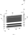
FIG. 1 is an exploded view of a heat exchanger in an embodiment. -
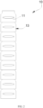
FIG. 2 is a structural schematic diagram of a collecting pipe of a heat exchanger in an embodiment. -
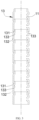
FIG. 3 is a section view of a collecting pipe of a heat exchanger in an embodiment. -
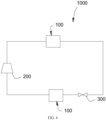
FIG. 4 is a schematic diagram of a refrigeration system in an embodiment. - In the figures, 1000 represents a refrigeration system, 100 represents a heat exchanger, 10 represents a collecting pipe, 11 represents a slot, 12 represents a connecting pipe, 13 represents a pipe units, 131 represents a first section, 132 represents a second section, 133 represents an arc-shaped section, 14 represents an end cover, 20 represents a heat exchange pipe, 30 represents a fin, 40 represents a sideboard, 200 represents a compressor, and 300 represents a throttling element.
- A clear and complete description of the technical solutions in the embodiments of the present invention will be given below in conjunction with the accompanying drawings in the embodiments of the present invention. It will be apparent that the described embodiments are only a part and not all of the embodiments of the present invention. Based on the embodiments in the present invention, all other embodiments obtained by those of ordinary skill in the art without creative work fall within the protection scope of the present invention provided they are within the scope of the appended claims.
- It should be noted that when an element is referred to as being "arranged" on another element, it may be directly arranged on the other element or a further element may be presented between them. When an element is referred to as being "disposed" on another element, it may be directly disposed on the other element or a further element may be presented between them. When an element is referred to as being "fixed" to another element, it may be directly attached to the other element or a further element may be presented between them.
- Unless otherwise defined, all technical and scientific terms used herein have the same meaning as commonly understood by one of ordinary skill in the art of the present invention. The term "or/and" as used herein includes any and all combinations of one or more of the associated listed items.
- Referring to
FIG. 4 , the present invention provides arefrigeration system 1000. Therefrigeration system 1000 is applied to a cold chain system such as a household air conditioner, a refrigerator, a commercial air conditioner freezer, or a cold storage, or other occasions that need to reduce or raise a temperature of natural environment. - The
refrigeration system 1000 includes acompressor 200, athrottling element 300 and aheat exchanger 100, and thecompressor 200, the throttlingelement 300 and theheat exchanger 100 are connected to each other by pipelines. Other accessories such as liquid reservoirs and gas-liquid separators between thecompressor 200, the throttlingelement 300 and theheat exchanger 100 can also be provided. - Referring to
FIG. 1 to FIG. 3 , theheat exchanger 100 includes a collectingpipe 10 and a plurality ofheat exchange pipes 20. The collectingpipe 10 is disposed at both ends of theheat exchange pipe 20, respectively, and the plurality ofheat exchange pipes 20 are arranged in parallel with each other. The collectingpipe 10 is provided with a plurality ofslots 11, and the plurality ofheat exchange pipes 20 are inserted into correspondingslot 11, resulting in the collectingpipe 10 and the plurality ofheat exchange pipes 20 are in communication with each other. The number of theheat exchange pipes 20 corresponds to the number of theslots 11 one-to-one. - Specifically, the
heat exchanger 100 further includes a plurality offins 30 disposed between adjacent two of the plurality ofheat exchange pipes 20, that is, afin 30 is disposed between adjacent two of the plurality ofheat exchange pipes 20. The plurality offins 30 are distributed from one end of the plurality of heat exchange pipes to the other end thereof, thus enhancing a heat exchange between a medium in theheat exchange pipe 20 and the external environment. - Furthermore, the
heat exchanger 100 further includes twosideboards 40, the twosideboards 40 are disposed on an outside of a top one and a bottom one of the plurality offins 30 respectively, and fixed to the top one and the bottom one of the plurality offins 30 respectively to protect them. - The collecting
pipes 10 are located on both sides of theheat exchange pipe 20, that is, the number of the collectingpipes 10 is two, and an end of each of the collectingpipes 10 is provided with a connectingpipe 12, wherein one of the connectingpipes 12 is defined as aninlet connecting pipe 12, and the other thereof is defined as anoutlet connecting pipe 12, and medium flows into the collectingpipes 10 by theinlet connecting pipe 12 and flows out the collectingpipe 10 by theoutlet connecting pipe 12. When theheat exchanger 100 is used as a condenser, the medium in theheat exchange pipe 20 releases heat to outside environment via the plurality offins 30. Theinlet connecting pipe 12 is connected to an outlet of thecompressor 200, and theoutlet connecting pipe 12 is connected to an inlet of thethrottling element 300. Of course, other accessories such as oil separators can be provided between theinlet connecting pipe 12 and thecompressor 200, and other accessories such as reservoirs can be provided between theoutlet connecting pipe 12 and thethrottling element 300. When theheat exchanger 100 is used as an evaporator, the medium in theheat exchange pipe 20 absorbs heat from outside environment via the plurality offins 30. Theinlet connecting pipe 12 is connected to an outlet of thethrottling element 300, theoutlet connecting pipe 12 is connected to an inlet of thecompressor 200. Of course, other accessories such as ball valves can be provided between theinlet connecting pipe 12 and thethrottling element 300, and other accessories such as gas-liquid separators can be provided between theoutlet connecting pipe 12 and thecompressor 200. - Referring to
FIG. 2 to FIG. 3 , the collectingpipe 10 includes a plurality ofpipe units 13, and the plurality ofpipe units 13 are sequentially stacked and connected along an axis of the collecting pipe. - Specifically, each of the plurality of
pipe units 13 includes afirst section 131 and asecond section 132, and a diameter of thefirst section 131 is less than that of thesecond section 132, such that thefirst section 131 of one of adjacent two of the plurality ofpipe units 13 is capable of being inserted into and fixed to thesecond section 132 of the other of adjacent two of the plurality ofpipe units 13 by welding process. - It is understood that before welding, surfaces of the collecting
pipe 10 and theheat exchange pipe 20 are coated with a composite layer. It is necessary to explain that the composite layer is a brazing material. In a conventional art, during welding, theheat exchanger 100 is placed in a brazing furnace, and high temperature environment causes the brazing material to melt, so that theheat exchange pipe 20 and the collectingpipe 10 are lowered/sunk, and theheat exchange pipe 20 is lowered/sunk more significant than the collectingpipe 10. Two ends of the plurality ofheat exchange pipes 20 are inserted into correspondingslot 11 of the collectingpipe 10 and restricted by a notch of theslot 11, a sinking in a middle of theheat exchange pipe 20 may be more serious than that of the both sides. An overall structure of theheat exchange pipe 20 may be deformed, and theheat exchange pipe 20 and theslot 11 may be also tilted, which can easily lead to virtual welding and desoldering during welding. However, in the present invention, the first section of one of adjacent two of the plurality of pipe units is inserted into the second section of the other of adjacent two of the plurality of pipe units, providing an expansion allowance for a sinking of each of the plurality of pipe units. So that the collecting pipe and the heat exchange pipe are lowered/sunk synchronously, and welding efficiency is improved. - Furthermore, an arc-shaped section is provided between the first section and the second section of each of the plurality of pipe units, and the arc-shaped section extends to a top of the second section from a bottom of the first section, thus avoiding a stress concentration due to the direct connection between the
first section 131 and thesecond section 132. Since the medium inside the collectingpipe 10 is in a variable load, that is, an impact force of the medium inside the collectingpipe 10 on an inner wall of the collectingpipe 10 is not constant. Under a long-term impact of the medium or a vibrating environment, a direct connection between thefirst section 131 and thesecond section 132 will cause a joint between thefirst section 131 and thesecond section 132 to fracture due to the stress concentration. The arc-shapedsection 133 can reduce the stress concentration between the two and prolong a service life of theheat exchanger 100. - Alternatively, a length of the
first section 131 along an axis of the collectingpipe 10 is in a range of 2 mm to 6 mm. It is understood that a flow through the collectingpipe 10 will be reduced if the length of thefirst section 131 is too great, and it will not be possible to provide the expansion allowance for the sinking of collectingpipe 10 if a length of thesecond section 132 is too small. Therefore, 2 mm to 6 mm of the length of thefirst section 131 can be a suitable range. The length of thefirst section 131 can be 2 mm, 2.5 mm, 3 mm, 3.8 mm, 4 mm, 4.5 mm, 5 mm, 5.3 mm, 6 mm or any value between 2 mm to 6 mm. - Before welding, the
first section 131 of one of adjacent two of the plurality ofpipe units 13 is inserted into thesecond section 132 of the other of adjacent two of the plurality ofpipe units 13, and a depth of a insertion part of thefirst section 131 is less than the length of thefirst section 131 to provide an expansion allowance for the sinking of each of the plurality ofpipe units 13. - Preferably, in the present embodiment, the length of the
first section 131 is 4 mm, and the depth of the insertion part of thefirst section 131 is 2 mm. In other embodiments, the length of thefirst section 131 can be other values, and the depth of the insertion part of thefirst section 131 can be other values. - A gap is defined between the
first section 131 of the one of adjacent two of the plurality ofpipe units 13 and thesecond section 132 of the other of adjacent two of the plurality ofpipe units 13 and in a size of 0.1 mm. Said gap between thefirst section 131 of the one of adjacent two of the plurality ofpipe units 13 and thesecond section 132 of the other of adjacent two of the plurality ofpipe units 13, not only enables thefirst section 131 of one of adjacent two of the plurality ofpipe units 13 to insert smoothly into thesecond section 132 of the other of adjacent two of the plurality ofpipe units 13, but also prevents the gap between the two from being too large and an occurrence of lack of welding. - Furthermore, in each of the plurality of
pipe units 13, thefirst section 131, the arc-shapedsection 133, and thesecond section 132 are combined as an integrity structure. In this way, it is possible to simplify a welding process between thefirst section 131, the arc-shapedsection 133, and thesecond section 132 of each of the plurality ofpipe units 13, thus avoiding the occurrence of lack of welding and increasing reliability of theheat exchanger 100. - Referring to
FIG. 3 , thefirst section 131 is formed by an end of each of the plurality ofpipe units 13 via a narrowing-mouth process. The process is simple and requires no additional welding. - Preferably, a length of each of the plurality of
pipe units 13 is the same, a height of each of the plurality ofpipe units 13 is all the same. The length of thefirst section 131 of each of the plurality ofpipe units 13 is the same, an inner diameter of thefirst section 131 of each of the plurality ofpipe units 13 is all the same, an outer diameter of thefirst section 131 of each of the plurality ofpipe units 13 is the same. The length of thesecond section 132 of each of the plurality ofpipe units 13 is the same, an inner diameter of thesecond section 132 of each of the plurality ofpipe units 13 is all the same, an outer diameter of thesecond section 132 of each of the plurality ofpipe units 13 is the same. A radian of the arc-shapedsection 133 of each of the plurality ofpipe units 13 is the same, and it is convenient to process. Of course, in other embodiments, according to different designs, the length and the height of each of the plurality ofpipe units 13 can be different, the length, the inner diameter and the outer diameter of thefirst section 131 and thesecond section 132 of each section of thepipe unit 13 can also be different, and the radian of the arc-shapedsection 133 of each of the plurality ofpipe units 13 can also be different. - A top one and a bottom one of the plurality of
pipe units 13 are provide with anend cover 14 respectively, that is, both ends of the collectingpipe 10 are provided with theend cover 14. Theend cover 14 is configured for sealing the collectingpipe 10 to prevent the medium inside the collectingpipe 10 from getting leakage. - During an assembly process, the
first section 131 of one of adjacent two of the plurality ofpipe units 13 is inserted into thesecond section 132 of the other of adjacent two of the plurality ofpipe units 13, and surfaces of the collectingpipe 10 and theheat exchange pipe 20 are coated with the composite layer. Then the plurality ofheat exchange pipes 20 are inserted into correspondingslot 11 and put into the brazing furnace for welding. The composite layer is melted due to high temperature, so that theheat exchange pipe 20 and the collectingpipe 10 may be lowered/sunk. The collectingpipe 10 has the expansion allowance due to a mutual insertion between thefirst section 131 and thesecond section 132 of the plurality ofpipe units 13, so that the collectingpipe 10 and theheat exchange pipe 20 are lowered synchronously. After the composite layer is melted, the plurality ofpipe units 13 and theheat exchange pipe 20 are welded into a whole. - During a working process, the arc-shaped
section 133 between thefirst section 131 and thesecond section 132 can reduce the stress concentration at the joint between thefirst section 131 and thesecond section 132, which can prevent from breakage under a long-term use in the vibrating environment or the impact of the medium. - The technical features of the above-described embodiments may be combined in any combination. For the sake of brevity of description, not all possible combinations of the technical features in the above embodiments are described. However, as long as there is no contradiction between the combinations of these technical features, all should be considered as within the scope of this invention provided they are within the scope of the appended claims.
Claims (9)
- A heat exchanger (100) comprising a collecting pipe (10), wherein the collecting pipe (10) comprises a plurality of pipe units (13), the plurality of pipe units (13) are sequentially stacked and connected, each of the plurality of pipe units (13) comprises a first section (131) and a second section (132), and a diameter of the first section (131) is less than that of the second section (132), such that the first section (131) of one of adjacent two of the plurality of pipe units (13) is capable of inserting into the second section (132) of the other of adjacent two of the plurality of pipe units (13),an arc-shaped section (133) is provided between the first section (131) and the second section (132) of each of the plurality of pipe units (13), and the arc-shaped section (133) extends to a top of the second section (132) from a bottom of the first section (131), so that the first section (131) is connected to the second section (132), characterized in thata gap is defined between the first section (131) of the one of adjacent two of the plurality of pipe units (13) and the second section (132) of the other of adjacent two of the plurality of pipe units (13) and in a size of 0.1 mm.
- The heat exchanger (100) of claim 1, wherein a length of the first section (131) along an axis of the collecting pipe (10) is in a range of 2 mm to 6 mm.
- The heat exchanger (100) of claim 1, wherein in each of the plurality of pipe units (13), the first section (131), the arc-shaped section (133), and the second section (132) are combined as an integrity structure.
- The heat exchanger (100) of claim 1, wherein a radian of the arc-shaped section (133) of each of the plurality of pipe units (13) is the same.
- The heat exchanger (100) of claim 1, wherein the first section (131) is formed by an end of each of the plurality of pipe units (13) via a narrowing-mouth process.
- The heat exchanger (100) of claim 1, further comprising a plurality of heat exchange pipes (20), each of the plurality of pipe units (13) is provided with a slot (11), and two ends of the plurality of heat exchange pipes (20) are inserted into corresponding slot (11), resulting in the collecting pipe (10) and the plurality of heat exchange pipes (20) are in communication with each other.
- The heat exchanger (100) of claim 1, wherein a top one and a bottom one of the plurality of pipe units (13) are provide with an end cover (14) respectively, and the end cover (14) is configured for sealing the collecting pipe (10).
- The heat exchanger (100) of claim 6, further comprising a plurality of fins (30) disposed between adjacent two of the plurality of heat exchange pipes (20) and distributed from one end of the plurality of heat exchange pipes (20) to the other end thereof.
- A refrigeration system (1000) comprising a compressor (200), a throttling element (300), and the heat exchanger (100) of any one of claims 1 to 8, wherein the heat exchanger (100) is connected and in communication with the compressor (200) and the throttling element (300) respectively.
Applications Claiming Priority (2)
| Application Number | Priority Date | Filing Date | Title |
|---|---|---|---|
| CN201922374776.0U CN212157731U (en) | 2019-12-25 | 2019-12-25 | Heat exchanger and refrigerating system |
| PCT/CN2020/136137 WO2021129440A1 (en) | 2019-12-25 | 2020-12-14 | Heat exchanger and refrigeration system |
Publications (4)
| Publication Number | Publication Date |
|---|---|
| EP4067805A1 EP4067805A1 (en) | 2022-10-05 |
| EP4067805A4 EP4067805A4 (en) | 2023-01-04 |
| EP4067805C0 EP4067805C0 (en) | 2025-05-14 |
| EP4067805B1 true EP4067805B1 (en) | 2025-05-14 |
Family
ID=73704938
Family Applications (1)
| Application Number | Title | Priority Date | Filing Date |
|---|---|---|---|
| EP20906651.3A Active EP4067805B1 (en) | 2019-12-25 | 2020-12-14 | Heat exchanger and refrigeration system |
Country Status (6)
| Country | Link |
|---|---|
| EP (1) | EP4067805B1 (en) |
| JP (1) | JP2023507904A (en) |
| KR (1) | KR20220098388A (en) |
| CN (1) | CN212157731U (en) |
| ES (1) | ES3029083T3 (en) |
| WO (1) | WO2021129440A1 (en) |
Family Cites Families (10)
| Publication number | Priority date | Publication date | Assignee | Title |
|---|---|---|---|---|
| JPH0631689B2 (en) * | 1987-12-24 | 1994-04-27 | 日本電装株式会社 | Heat exchanger |
| JPH01203890A (en) * | 1988-02-08 | 1989-08-16 | Nippon Denso Co Ltd | Heat exchanger |
| JPH0229594A (en) * | 1988-04-28 | 1990-01-31 | Nippon Denso Co Ltd | Heat exchanger |
| JPH0886591A (en) * | 1994-07-22 | 1996-04-02 | Nippondenso Co Ltd | Heat exchanger and refrigerant evaporator |
| JP2001263989A (en) * | 2000-03-17 | 2001-09-26 | Kobe Steel Ltd | Drawn cup type heat-exchanger |
| KR20010068204A (en) * | 2000-07-03 | 2001-07-23 | 배길훈 | Head assembly of heat exchange for vehicle |
| DE10112697A1 (en) * | 2001-03-16 | 2002-09-19 | Behr Gmbh & Co | Heat transfer radiator has adjacent segments with connection regions for insertion into each other |
| EP1369658A1 (en) * | 2002-06-03 | 2003-12-10 | VALMEX S.p.A. | Radiating element and relative radiator |
| FR2858385B1 (en) * | 2003-07-29 | 2006-02-17 | Valeo Thermique Moteur Sa | TUBE BIT FOR HYDRAULIC CIRCUIT ELEMENT, ESPECIALLY FOR HEAT EXCHANGER |
| CN106440523A (en) * | 2016-08-29 | 2017-02-22 | 扬州派斯特换热设备有限公司 | Efficient parallel flow heat exchanger |
-
2019
- 2019-12-25 CN CN201922374776.0U patent/CN212157731U/en active Active
-
2020
- 2020-12-14 JP JP2022532028A patent/JP2023507904A/en active Pending
- 2020-12-14 KR KR1020227021478A patent/KR20220098388A/en not_active Ceased
- 2020-12-14 ES ES20906651T patent/ES3029083T3/en active Active
- 2020-12-14 EP EP20906651.3A patent/EP4067805B1/en active Active
- 2020-12-14 WO PCT/CN2020/136137 patent/WO2021129440A1/en not_active Ceased
Also Published As
| Publication number | Publication date |
|---|---|
| EP4067805A1 (en) | 2022-10-05 |
| EP4067805C0 (en) | 2025-05-14 |
| JP2023507904A (en) | 2023-02-28 |
| WO2021129440A1 (en) | 2021-07-01 |
| EP4067805A4 (en) | 2023-01-04 |
| ES3029083T3 (en) | 2025-06-23 |
| CN212157731U (en) | 2020-12-15 |
| KR20220098388A (en) | 2022-07-12 |
Similar Documents
| Publication | Publication Date | Title |
|---|---|---|
| KR100893169B1 (en) | Heat exchanger module | |
| JP5768480B2 (en) | Cold storage heat exchanger | |
| JP6180281B2 (en) | Heat exchanger with heat storage function and manufacturing method thereof | |
| US9746245B2 (en) | Heat exchanger equipped with cold reserving part and manufacturing method thereof | |
| MX2007009248A (en) | Parallel flow heat exchanger with crimped channel entrance. | |
| JP2013231532A (en) | Heat exchanger with heat storage function and its manufacturing method | |
| JP2015087086A5 (en) | ||
| EP1477758A2 (en) | Multi-function heat exchanger | |
| KR20120044851A (en) | Heat exchanger | |
| JP2014055736A (en) | Heat exchanger | |
| KR20120044849A (en) | Header and heat exchanger having the same | |
| WO2015045344A1 (en) | Cold-storage heat exchanger | |
| JP2007278556A (en) | Heat exchanger | |
| WO2016170751A1 (en) | Cold storage heat exchanger | |
| KR20220113273A (en) | Connector and Heat exchanger for vehicle having the same | |
| JP2011133126A (en) | Evaporator with cold storage function | |
| JP2011242098A (en) | Evaporator having cold storage function | |
| JP2015010740A (en) | Cold storage heat exchanger and manufacturing method thereof | |
| JP6826133B2 (en) | Heat exchanger and refrigeration cycle equipment | |
| KR20170011736A (en) | A tube for heat exchanger | |
| JP2007078292A (en) | Heat exchanger and double heat exchanger | |
| JP2006322636A (en) | Heat exchanger | |
| KR101461077B1 (en) | Heat exchanger | |
| EP4067805A1 (en) | Heat exchanger and refrigeration system | |
| JP2004183960A (en) | Heat exchanger |
Legal Events
| Date | Code | Title | Description |
|---|---|---|---|
| STAA | Information on the status of an ep patent application or granted ep patent |
Free format text: STATUS: THE INTERNATIONAL PUBLICATION HAS BEEN MADE |
|
| PUAI | Public reference made under article 153(3) epc to a published international application that has entered the european phase |
Free format text: ORIGINAL CODE: 0009012 |
|
| STAA | Information on the status of an ep patent application or granted ep patent |
Free format text: STATUS: REQUEST FOR EXAMINATION WAS MADE |
|
| 17P | Request for examination filed |
Effective date: 20220630 |
|
| AK | Designated contracting states |
Kind code of ref document: A1 Designated state(s): AL AT BE BG CH CY CZ DE DK EE ES FI FR GB GR HR HU IE IS IT LI LT LU LV MC MK MT NL NO PL PT RO RS SE SI SK SM TR |
|
| A4 | Supplementary search report drawn up and despatched |
Effective date: 20221206 |
|
| RIC1 | Information provided on ipc code assigned before grant |
Ipc: F28D 1/053 20060101ALI20221130BHEP Ipc: F28F 9/02 20060101AFI20221130BHEP |
|
| DAV | Request for validation of the european patent (deleted) | ||
| DAX | Request for extension of the european patent (deleted) | ||
| GRAP | Despatch of communication of intention to grant a patent |
Free format text: ORIGINAL CODE: EPIDOSNIGR1 |
|
| STAA | Information on the status of an ep patent application or granted ep patent |
Free format text: STATUS: GRANT OF PATENT IS INTENDED |
|
| INTG | Intention to grant announced |
Effective date: 20241209 |
|
| RIN1 | Information on inventor provided before grant (corrected) |
Inventor name: MA, WENYONG Inventor name: LAN, ZHAOZHONG Inventor name: WEI, WENJIAN |
|
| GRAS | Grant fee paid |
Free format text: ORIGINAL CODE: EPIDOSNIGR3 |
|
| GRAA | (expected) grant |
Free format text: ORIGINAL CODE: 0009210 |
|
| STAA | Information on the status of an ep patent application or granted ep patent |
Free format text: STATUS: THE PATENT HAS BEEN GRANTED |
|
| AK | Designated contracting states |
Kind code of ref document: B1 Designated state(s): AL AT BE BG CH CY CZ DE DK EE ES FI FR GB GR HR HU IE IS IT LI LT LU LV MC MK MT NL NO PL PT RO RS SE SI SK SM TR |
|
| REG | Reference to a national code |
Ref country code: GB Ref legal event code: FG4D |
|
| REG | Reference to a national code |
Ref country code: CH Ref legal event code: EP |
|
| REG | Reference to a national code |
Ref country code: IE Ref legal event code: FG4D |
|
| REG | Reference to a national code |
Ref country code: ES Ref legal event code: FG2A Ref document number: 3029083 Country of ref document: ES Kind code of ref document: T3 Effective date: 20250623 |
|
| U01 | Request for unitary effect filed |
Effective date: 20250519 |
|
| U07 | Unitary effect registered |
Designated state(s): AT BE BG DE DK EE FI FR IT LT LU LV MT NL PT RO SE SI Effective date: 20250526 |
|
| PG25 | Lapsed in a contracting state [announced via postgrant information from national office to epo] |
Ref country code: NO Free format text: LAPSE BECAUSE OF FAILURE TO SUBMIT A TRANSLATION OF THE DESCRIPTION OR TO PAY THE FEE WITHIN THE PRESCRIBED TIME-LIMIT Effective date: 20250814 Ref country code: GR Free format text: LAPSE BECAUSE OF FAILURE TO SUBMIT A TRANSLATION OF THE DESCRIPTION OR TO PAY THE FEE WITHIN THE PRESCRIBED TIME-LIMIT Effective date: 20250815 |
|
| PG25 | Lapsed in a contracting state [announced via postgrant information from national office to epo] |
Ref country code: PL Free format text: LAPSE BECAUSE OF FAILURE TO SUBMIT A TRANSLATION OF THE DESCRIPTION OR TO PAY THE FEE WITHIN THE PRESCRIBED TIME-LIMIT Effective date: 20250514 |
|
| PG25 | Lapsed in a contracting state [announced via postgrant information from national office to epo] |
Ref country code: HR Free format text: LAPSE BECAUSE OF FAILURE TO SUBMIT A TRANSLATION OF THE DESCRIPTION OR TO PAY THE FEE WITHIN THE PRESCRIBED TIME-LIMIT Effective date: 20250514 |
|
| PG25 | Lapsed in a contracting state [announced via postgrant information from national office to epo] |
Ref country code: RS Free format text: LAPSE BECAUSE OF FAILURE TO SUBMIT A TRANSLATION OF THE DESCRIPTION OR TO PAY THE FEE WITHIN THE PRESCRIBED TIME-LIMIT Effective date: 20250814 |
|
| PG25 | Lapsed in a contracting state [announced via postgrant information from national office to epo] |
Ref country code: IS Free format text: LAPSE BECAUSE OF FAILURE TO SUBMIT A TRANSLATION OF THE DESCRIPTION OR TO PAY THE FEE WITHIN THE PRESCRIBED TIME-LIMIT Effective date: 20250914 |
|
| PGFP | Annual fee paid to national office [announced via postgrant information from national office to epo] |
Ref country code: GB Payment date: 20251121 Year of fee payment: 6 |
|
| PG25 | Lapsed in a contracting state [announced via postgrant information from national office to epo] |
Ref country code: SM Free format text: LAPSE BECAUSE OF FAILURE TO SUBMIT A TRANSLATION OF THE DESCRIPTION OR TO PAY THE FEE WITHIN THE PRESCRIBED TIME-LIMIT Effective date: 20250514 |
|
| PG25 | Lapsed in a contracting state [announced via postgrant information from national office to epo] |
Ref country code: CZ Free format text: LAPSE BECAUSE OF FAILURE TO SUBMIT A TRANSLATION OF THE DESCRIPTION OR TO PAY THE FEE WITHIN THE PRESCRIBED TIME-LIMIT Effective date: 20250514 |
|
| U20 | Renewal fee for the european patent with unitary effect paid |
Year of fee payment: 6 Effective date: 20251211 |
|
| PG25 | Lapsed in a contracting state [announced via postgrant information from national office to epo] |
Ref country code: SK Free format text: LAPSE BECAUSE OF FAILURE TO SUBMIT A TRANSLATION OF THE DESCRIPTION OR TO PAY THE FEE WITHIN THE PRESCRIBED TIME-LIMIT Effective date: 20250514 |
|
| PLBE | No opposition filed within time limit |
Free format text: ORIGINAL CODE: 0009261 |
|
| STAA | Information on the status of an ep patent application or granted ep patent |
Free format text: STATUS: NO OPPOSITION FILED WITHIN TIME LIMIT |
|
| REG | Reference to a national code |
Ref country code: CH Ref legal event code: L10 Free format text: ST27 STATUS EVENT CODE: U-0-0-L10-L00 (AS PROVIDED BY THE NATIONAL OFFICE) Effective date: 20260325 |
|
| PGFP | Annual fee paid to national office [announced via postgrant information from national office to epo] |
Ref country code: ES Payment date: 20260112 Year of fee payment: 6 |
|
| 26N | No opposition filed |
Effective date: 20260217 |