EP4067771A1 - Silent device for air conditioning equipment - Google Patents
Silent device for air conditioning equipment Download PDFInfo
- Publication number
- EP4067771A1 EP4067771A1 EP20892965.3A EP20892965A EP4067771A1 EP 4067771 A1 EP4067771 A1 EP 4067771A1 EP 20892965 A EP20892965 A EP 20892965A EP 4067771 A1 EP4067771 A1 EP 4067771A1
- Authority
- EP
- European Patent Office
- Prior art keywords
- duct
- speaker
- noise
- silencer
- microphone
- Prior art date
- Legal status (The legal status is an assumption and is not a legal conclusion. Google has not performed a legal analysis and makes no representation as to the accuracy of the status listed.)
- Withdrawn
Links
- 238000004378 air conditioning Methods 0.000 title description 8
- 230000003584 silencer Effects 0.000 claims description 45
- 239000011358 absorbing material Substances 0.000 claims description 33
- 230000002787 reinforcement Effects 0.000 claims description 3
- 230000030279 gene silencing Effects 0.000 description 11
- 239000000470 constituent Substances 0.000 description 4
- 210000005069 ears Anatomy 0.000 description 4
- 230000000694 effects Effects 0.000 description 4
- 239000000463 material Substances 0.000 description 4
- 230000001743 silencing effect Effects 0.000 description 4
- 238000010521 absorption reaction Methods 0.000 description 3
- 239000000835 fiber Substances 0.000 description 3
- 230000003014 reinforcing effect Effects 0.000 description 3
- 238000003466 welding Methods 0.000 description 3
- CURLTUGMZLYLDI-UHFFFAOYSA-N Carbon dioxide Chemical compound O=C=O CURLTUGMZLYLDI-UHFFFAOYSA-N 0.000 description 2
- 238000010586 diagram Methods 0.000 description 2
- 239000002121 nanofiber Substances 0.000 description 2
- 230000009467 reduction Effects 0.000 description 2
- 230000007480 spreading Effects 0.000 description 2
- JOYRKODLDBILNP-UHFFFAOYSA-N Ethyl urethane Chemical compound CCOC(N)=O JOYRKODLDBILNP-UHFFFAOYSA-N 0.000 description 1
- 239000000853 adhesive Substances 0.000 description 1
- 230000001070 adhesive effect Effects 0.000 description 1
- 229910002092 carbon dioxide Inorganic materials 0.000 description 1
- 239000001569 carbon dioxide Substances 0.000 description 1
- 230000008859 change Effects 0.000 description 1
- 230000003247 decreasing effect Effects 0.000 description 1
- 238000001514 detection method Methods 0.000 description 1
- 238000007599 discharging Methods 0.000 description 1
- 230000001747 exhibiting effect Effects 0.000 description 1
- 239000012530 fluid Substances 0.000 description 1
- 239000006260 foam Substances 0.000 description 1
- 239000011491 glass wool Substances 0.000 description 1
- 239000005431 greenhouse gas Substances 0.000 description 1
- 238000010438 heat treatment Methods 0.000 description 1
- 238000000034 method Methods 0.000 description 1
- 230000008569 process Effects 0.000 description 1
- 230000001105 regulatory effect Effects 0.000 description 1
- 239000007787 solid Substances 0.000 description 1
- 238000009423 ventilation Methods 0.000 description 1
- 238000010792 warming Methods 0.000 description 1
Images


Classifications
-
- G—PHYSICS
- G10—MUSICAL INSTRUMENTS; ACOUSTICS
- G10K—SOUND-PRODUCING DEVICES; METHODS OR DEVICES FOR PROTECTING AGAINST, OR FOR DAMPING, NOISE OR OTHER ACOUSTIC WAVES IN GENERAL; ACOUSTICS NOT OTHERWISE PROVIDED FOR
- G10K11/00—Methods or devices for transmitting, conducting or directing sound in general; Methods or devices for protecting against, or for damping, noise or other acoustic waves in general
- G10K11/16—Methods or devices for protecting against, or for damping, noise or other acoustic waves in general
- G10K11/175—Methods or devices for protecting against, or for damping, noise or other acoustic waves in general using interference effects; Masking sound
- G10K11/178—Methods or devices for protecting against, or for damping, noise or other acoustic waves in general using interference effects; Masking sound by electro-acoustically regenerating the original acoustic waves in anti-phase
- G10K11/1785—Methods, e.g. algorithms; Devices
- G10K11/17857—Geometric disposition, e.g. placement of microphones
-
- G—PHYSICS
- G10—MUSICAL INSTRUMENTS; ACOUSTICS
- G10K—SOUND-PRODUCING DEVICES; METHODS OR DEVICES FOR PROTECTING AGAINST, OR FOR DAMPING, NOISE OR OTHER ACOUSTIC WAVES IN GENERAL; ACOUSTICS NOT OTHERWISE PROVIDED FOR
- G10K11/00—Methods or devices for transmitting, conducting or directing sound in general; Methods or devices for protecting against, or for damping, noise or other acoustic waves in general
- G10K11/16—Methods or devices for protecting against, or for damping, noise or other acoustic waves in general
-
- F—MECHANICAL ENGINEERING; LIGHTING; HEATING; WEAPONS; BLASTING
- F04—POSITIVE - DISPLACEMENT MACHINES FOR LIQUIDS; PUMPS FOR LIQUIDS OR ELASTIC FLUIDS
- F04D—NON-POSITIVE-DISPLACEMENT PUMPS
- F04D29/00—Details, component parts, or accessories
- F04D29/66—Combating cavitation, whirls, noise, vibration or the like; Balancing
- F04D29/661—Combating cavitation, whirls, noise, vibration or the like; Balancing especially adapted for elastic fluid pumps
- F04D29/663—Sound attenuation
- F04D29/665—Sound attenuation by means of resonance chambers or interference
-
- B—PERFORMING OPERATIONS; TRANSPORTING
- B60—VEHICLES IN GENERAL
- B60H—ARRANGEMENTS OF HEATING, COOLING, VENTILATING OR OTHER AIR-TREATING DEVICES SPECIALLY ADAPTED FOR PASSENGER OR GOODS SPACES OF VEHICLES
- B60H1/00—Heating, cooling or ventilating [HVAC] devices
- B60H1/00507—Details, e.g. mounting arrangements, desaeration devices
- B60H1/00557—Details of ducts or cables
- B60H1/00564—Details of ducts or cables of air ducts
-
- F—MECHANICAL ENGINEERING; LIGHTING; HEATING; WEAPONS; BLASTING
- F04—POSITIVE - DISPLACEMENT MACHINES FOR LIQUIDS; PUMPS FOR LIQUIDS OR ELASTIC FLUIDS
- F04D—NON-POSITIVE-DISPLACEMENT PUMPS
- F04D29/00—Details, component parts, or accessories
- F04D29/66—Combating cavitation, whirls, noise, vibration or the like; Balancing
- F04D29/661—Combating cavitation, whirls, noise, vibration or the like; Balancing especially adapted for elastic fluid pumps
- F04D29/663—Sound attenuation
- F04D29/664—Sound attenuation by means of sound absorbing material
-
- F—MECHANICAL ENGINEERING; LIGHTING; HEATING; WEAPONS; BLASTING
- F24—HEATING; RANGES; VENTILATING
- F24F—AIR-CONDITIONING; AIR-HUMIDIFICATION; VENTILATION; USE OF AIR CURRENTS FOR SCREENING
- F24F13/00—Details common to, or for air-conditioning, air-humidification, ventilation or use of air currents for screening
- F24F13/02—Ducting arrangements
- F24F13/0263—Insulation for air ducts
-
- F—MECHANICAL ENGINEERING; LIGHTING; HEATING; WEAPONS; BLASTING
- F24—HEATING; RANGES; VENTILATING
- F24F—AIR-CONDITIONING; AIR-HUMIDIFICATION; VENTILATION; USE OF AIR CURRENTS FOR SCREENING
- F24F13/00—Details common to, or for air-conditioning, air-humidification, ventilation or use of air currents for screening
- F24F13/24—Means for preventing or suppressing noise
-
- G—PHYSICS
- G10—MUSICAL INSTRUMENTS; ACOUSTICS
- G10K—SOUND-PRODUCING DEVICES; METHODS OR DEVICES FOR PROTECTING AGAINST, OR FOR DAMPING, NOISE OR OTHER ACOUSTIC WAVES IN GENERAL; ACOUSTICS NOT OTHERWISE PROVIDED FOR
- G10K11/00—Methods or devices for transmitting, conducting or directing sound in general; Methods or devices for protecting against, or for damping, noise or other acoustic waves in general
- G10K11/16—Methods or devices for protecting against, or for damping, noise or other acoustic waves in general
- G10K11/175—Methods or devices for protecting against, or for damping, noise or other acoustic waves in general using interference effects; Masking sound
- G10K11/178—Methods or devices for protecting against, or for damping, noise or other acoustic waves in general using interference effects; Masking sound by electro-acoustically regenerating the original acoustic waves in anti-phase
- G10K11/1785—Methods, e.g. algorithms; Devices
- G10K11/17861—Methods, e.g. algorithms; Devices using additional means for damping sound, e.g. using sound absorbing panels
-
- G—PHYSICS
- G10—MUSICAL INSTRUMENTS; ACOUSTICS
- G10K—SOUND-PRODUCING DEVICES; METHODS OR DEVICES FOR PROTECTING AGAINST, OR FOR DAMPING, NOISE OR OTHER ACOUSTIC WAVES IN GENERAL; ACOUSTICS NOT OTHERWISE PROVIDED FOR
- G10K11/00—Methods or devices for transmitting, conducting or directing sound in general; Methods or devices for protecting against, or for damping, noise or other acoustic waves in general
- G10K11/16—Methods or devices for protecting against, or for damping, noise or other acoustic waves in general
- G10K11/175—Methods or devices for protecting against, or for damping, noise or other acoustic waves in general using interference effects; Masking sound
- G10K11/178—Methods or devices for protecting against, or for damping, noise or other acoustic waves in general using interference effects; Masking sound by electro-acoustically regenerating the original acoustic waves in anti-phase
- G10K11/1787—General system configurations
- G10K11/17879—General system configurations using both a reference signal and an error signal
- G10K11/17881—General system configurations using both a reference signal and an error signal the reference signal being an acoustic signal, e.g. recorded with a microphone
-
- H—ELECTRICITY
- H04—ELECTRIC COMMUNICATION TECHNIQUE
- H04R—LOUDSPEAKERS, MICROPHONES, GRAMOPHONE PICK-UPS OR LIKE ACOUSTIC ELECTROMECHANICAL TRANSDUCERS; DEAF-AID SETS; PUBLIC ADDRESS SYSTEMS
- H04R1/00—Details of transducers, loudspeakers or microphones
- H04R1/02—Casings; Cabinets ; Supports therefor; Mountings therein
- H04R1/028—Casings; Cabinets ; Supports therefor; Mountings therein associated with devices performing functions other than acoustics, e.g. electric candles
-
- H—ELECTRICITY
- H04—ELECTRIC COMMUNICATION TECHNIQUE
- H04R—LOUDSPEAKERS, MICROPHONES, GRAMOPHONE PICK-UPS OR LIKE ACOUSTIC ELECTROMECHANICAL TRANSDUCERS; DEAF-AID SETS; PUBLIC ADDRESS SYSTEMS
- H04R1/00—Details of transducers, loudspeakers or microphones
- H04R1/10—Earpieces; Attachments therefor ; Earphones; Monophonic headphones
- H04R1/1083—Reduction of ambient noise
-
- B—PERFORMING OPERATIONS; TRANSPORTING
- B60—VEHICLES IN GENERAL
- B60H—ARRANGEMENTS OF HEATING, COOLING, VENTILATING OR OTHER AIR-TREATING DEVICES SPECIALLY ADAPTED FOR PASSENGER OR GOODS SPACES OF VEHICLES
- B60H1/00—Heating, cooling or ventilating [HVAC] devices
- B60H1/00507—Details, e.g. mounting arrangements, desaeration devices
- B60H2001/006—Noise reduction
-
- F—MECHANICAL ENGINEERING; LIGHTING; HEATING; WEAPONS; BLASTING
- F05—INDEXING SCHEMES RELATING TO ENGINES OR PUMPS IN VARIOUS SUBCLASSES OF CLASSES F01-F04
- F05D—INDEXING SCHEME FOR ASPECTS RELATING TO NON-POSITIVE-DISPLACEMENT MACHINES OR ENGINES, GAS-TURBINES OR JET-PROPULSION PLANTS
- F05D2260/00—Function
- F05D2260/96—Preventing, counteracting or reducing vibration or noise
- F05D2260/962—Preventing, counteracting or reducing vibration or noise by means of "anti-noise"
-
- F—MECHANICAL ENGINEERING; LIGHTING; HEATING; WEAPONS; BLASTING
- F24—HEATING; RANGES; VENTILATING
- F24F—AIR-CONDITIONING; AIR-HUMIDIFICATION; VENTILATION; USE OF AIR CURRENTS FOR SCREENING
- F24F13/00—Details common to, or for air-conditioning, air-humidification, ventilation or use of air currents for screening
- F24F13/24—Means for preventing or suppressing noise
- F24F2013/247—Active noise-suppression
-
- F—MECHANICAL ENGINEERING; LIGHTING; HEATING; WEAPONS; BLASTING
- F24—HEATING; RANGES; VENTILATING
- F24F—AIR-CONDITIONING; AIR-HUMIDIFICATION; VENTILATION; USE OF AIR CURRENTS FOR SCREENING
- F24F2130/00—Control inputs relating to environmental factors not covered by group F24F2110/00
- F24F2130/40—Noise
-
- G—PHYSICS
- G10—MUSICAL INSTRUMENTS; ACOUSTICS
- G10K—SOUND-PRODUCING DEVICES; METHODS OR DEVICES FOR PROTECTING AGAINST, OR FOR DAMPING, NOISE OR OTHER ACOUSTIC WAVES IN GENERAL; ACOUSTICS NOT OTHERWISE PROVIDED FOR
- G10K2210/00—Details of active noise control [ANC] covered by G10K11/178 but not provided for in any of its subgroups
- G10K2210/10—Applications
- G10K2210/104—Aircos
-
- G—PHYSICS
- G10—MUSICAL INSTRUMENTS; ACOUSTICS
- G10K—SOUND-PRODUCING DEVICES; METHODS OR DEVICES FOR PROTECTING AGAINST, OR FOR DAMPING, NOISE OR OTHER ACOUSTIC WAVES IN GENERAL; ACOUSTICS NOT OTHERWISE PROVIDED FOR
- G10K2210/00—Details of active noise control [ANC] covered by G10K11/178 but not provided for in any of its subgroups
- G10K2210/10—Applications
- G10K2210/105—Appliances, e.g. washing machines or dishwashers
-
- G—PHYSICS
- G10—MUSICAL INSTRUMENTS; ACOUSTICS
- G10K—SOUND-PRODUCING DEVICES; METHODS OR DEVICES FOR PROTECTING AGAINST, OR FOR DAMPING, NOISE OR OTHER ACOUSTIC WAVES IN GENERAL; ACOUSTICS NOT OTHERWISE PROVIDED FOR
- G10K2210/00—Details of active noise control [ANC] covered by G10K11/178 but not provided for in any of its subgroups
- G10K2210/10—Applications
- G10K2210/112—Ducts
-
- G—PHYSICS
- G10—MUSICAL INSTRUMENTS; ACOUSTICS
- G10K—SOUND-PRODUCING DEVICES; METHODS OR DEVICES FOR PROTECTING AGAINST, OR FOR DAMPING, NOISE OR OTHER ACOUSTIC WAVES IN GENERAL; ACOUSTICS NOT OTHERWISE PROVIDED FOR
- G10K2210/00—Details of active noise control [ANC] covered by G10K11/178 but not provided for in any of its subgroups
- G10K2210/10—Applications
- G10K2210/128—Vehicles
- G10K2210/1282—Automobiles
-
- G—PHYSICS
- G10—MUSICAL INSTRUMENTS; ACOUSTICS
- G10K—SOUND-PRODUCING DEVICES; METHODS OR DEVICES FOR PROTECTING AGAINST, OR FOR DAMPING, NOISE OR OTHER ACOUSTIC WAVES IN GENERAL; ACOUSTICS NOT OTHERWISE PROVIDED FOR
- G10K2210/00—Details of active noise control [ANC] covered by G10K11/178 but not provided for in any of its subgroups
- G10K2210/30—Means
- G10K2210/321—Physical
- G10K2210/3223—Materials, e.g. special compositions or gases
-
- G—PHYSICS
- G10—MUSICAL INSTRUMENTS; ACOUSTICS
- G10K—SOUND-PRODUCING DEVICES; METHODS OR DEVICES FOR PROTECTING AGAINST, OR FOR DAMPING, NOISE OR OTHER ACOUSTIC WAVES IN GENERAL; ACOUSTICS NOT OTHERWISE PROVIDED FOR
- G10K2210/00—Details of active noise control [ANC] covered by G10K11/178 but not provided for in any of its subgroups
- G10K2210/30—Means
- G10K2210/321—Physical
- G10K2210/3224—Passive absorbers
-
- G—PHYSICS
- G10—MUSICAL INSTRUMENTS; ACOUSTICS
- G10K—SOUND-PRODUCING DEVICES; METHODS OR DEVICES FOR PROTECTING AGAINST, OR FOR DAMPING, NOISE OR OTHER ACOUSTIC WAVES IN GENERAL; ACOUSTICS NOT OTHERWISE PROVIDED FOR
- G10K2210/00—Details of active noise control [ANC] covered by G10K11/178 but not provided for in any of its subgroups
- G10K2210/50—Miscellaneous
- G10K2210/509—Hybrid, i.e. combining different technologies, e.g. passive and active
-
- H—ELECTRICITY
- H04—ELECTRIC COMMUNICATION TECHNIQUE
- H04R—LOUDSPEAKERS, MICROPHONES, GRAMOPHONE PICK-UPS OR LIKE ACOUSTIC ELECTROMECHANICAL TRANSDUCERS; DEAF-AID SETS; PUBLIC ADDRESS SYSTEMS
- H04R2410/00—Microphones
- H04R2410/05—Noise reduction with a separate noise microphone
Definitions
- the present disclosure relates to a silencer for an air conditioner, and more particularly, to a silencer for silencing air-conditioning noise caused by an air conditioner in a vehicle such as an automobile.
- Gasoline engines and diesel engines have been the main drive sources for automobiles.
- hybrid vehicles or electric vehicles including an electric motor as a part of a driving source to reduce greenhouse gas emissions such as carbon dioxide are rapidly spreading as a measure against the global warming.
- hybrid vehicles cause less engine noise, whereas electric vehicles cause no engine noise and bring silence.
- road noise within a range from 50 Hz to 500 Hz generated when tires roll on a road surface during a travel of an automobile, booming noise of 100 Hz or less caused by cabin resonance, fluid noise generated around side mirrors, and air-conditioning noise of tens of hertz to 10000 Hz generated by air-conditioning of an air conditioner.
- the air-conditioning noise is hard on the ears of an occupant.
- This type of vehicle includes an air conditioner attached near the rear seats to provide a comfortable space. Once the air conditioner operates, vibrations of a fan sucking outside air and aerodynamic noise of the sucked air are generated over a wide frequency range.
- PNC passive noise control
- Patent Document 1 Japanese Unexamined Patent Publication No. H05-172099
- a device includes an air intake member made of glass wool in an air flow passage to convert the noise generated at an intake side of a fan into thermal energy in the sound absorbing material and to eliminate noise.
- Other typical sound absorbing materials include an urethane foam or felt.
- Sound absorbing materials eliminate or reduce noise of 1000 Hz or more but fail to eliminate low-frequency noise less than the above frequency.
- the sound absorbing function is determined by the material and amount of a sound absorbing material. In order to increase the sound absorption efficiency, a larger amount of a sound absorbing material is needed. This requires a large structure and a large space and is thus not suitable for reducing the size and weight.
- the background art fails to cope with the type and change (e.g., from a lower range to a higher range or in the magnitude) of noise.
- the present disclosure was made in view of the foregoing. It is an objective of the present disclosure to provide a silencer, for an air conditioner, capable of eliminating low-frequency noise and exhibiting desired silencing performance.
- a silencer is for an air conditioner.
- the silencer includes: a first duct in a cylindrical shape at a noise outlet, the first duct including a reference microphone that detects noise as a reference signal; a speaker baffle on a top of the first duct, the speaker baffle having a circular shape as whole in a plan view and including a speaker around a center thereof; a back enclosure for the speaker, the back enclosure being on a back surface of the speaker baffle; a second duct that is in a shape of a cylinder and connected to a top of the speaker baffle; an error microphone in the second duct and above a diaphragm of the speaker at a distance to detect a control target signal which is an incompletely eliminated error signal; a cylindrical body for intake connected to a top of the second duct; and a duct cover for closing an upper opening of the cylindrical body.
- the noise is in a form of a first plane wave.
- the error microphone is configured to detect an error signal in the second duct.
- the speaker is configured to output a second plane wave with a phase opposite to a phase of the first plane wave.
- the silencer further includes: an ANC system connected to the speaker.
- the reference signal detected by the reference microphone is input to the ANC system connected to the reference microphone.
- the control target signal of the error microphone is input to the ANC system.
- An output of the ANC system is applied to the speaker connected. The speaker sends out the second plane wave.
- the acoustic path in the first duct includes a sound absorbing material.
- the duct cover has an inner surface including a cylinder serving as a wind shield and a reinforcement for the error microphone.
- the back enclosure for the speaker has a U-shaped side section.
- the silencer for the air conditioner located at the noise outlet functions as a sound absorbing duct and eliminates even low-frequency noise unable to be eliminated by a typical silencer made of only a sound absorbing material.
- the silencer includes the ANC system that generates a phase opposite to the phase of noise to attenuate the sound pressure of low-frequency noise and further improves the silencing effect.
- the sound absorbing member including, as a main material, the fibers with a high silencing effect is incorporated to eliminate noise over a wide frequency range from a low frequency to 1000 Hz or more.
- the duct cover has a higher rigidity to function as a sound absorbing duct with a higher strength, cause less vibrations, shields the error microphone from wind, and reliably operate the error microphone.
- the speaker has the back enclosure with a U-shaped side section forming an acoustic path, which smoothly guides the air and sound passing through the acoustic path and reduces noise.
- HVAC heating, ventilation, and air conditioning
- FIG. 19 is a schematic configuration diagram of an HVAC system.
- Reference character 100 denotes a case of the HVAC system with an upper surface 100a partially including a circular air inlet 101, in the state shown in the figure.
- Located inside is a rotatable fan 102 connected to a motor (not shown).
- the fan 102 is a centrifugal blower with a plurality of radial flat blades.
- the HVAC includes a radiator 103 functioning as a heater, an evaporator 104, and a shutter 105, for example.
- the air sucked into the case 100 through the air inlet 101 by the rotating fan 102 is cooled by the evaporator 104 or heated by the radiator 103 as indicated by an arrow, mixed at the degree regulated by the shutter 105, and then discharged through a discharge port.
- the air discharged from the HVAC system passes through a duct 106 to the foot of a passenger compartment and is sent through another duct 107 and an overhead air outlet to the passenger compartment around the rear seats (seats in the second and third rows).
- This HVAC is typically located in the interior material and the outer plate next to the seating surface of the seats in the third row. Once the HVAC is activated, the case 100 and the air inlet 101 emit the wide frequency-range operating noise caused by vibrations and aerodynamic noise. This operating noise passes through the interior material and the gaps between the interior components so as to become considerable noise for an occupant near the seats in the third row.
- an HVAC system is attached with a silencer for an air conditioner according to the embodiment of the present disclosure.
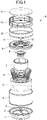
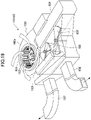
- FIG. 1 is an exploded perspective view of a silencer A for an air conditioner according to the embodiment of the present disclosure.
- the silencer A employs active noise control (ANC) for a low-frequency range and PNC for a high-frequency range to eliminate noise.
- ANC active noise control
- reference character 1 denotes a substantially cylindrical duct base attached to the top of a circular air inlet 101 of a case 100 of the HVAC shown in FIG. 19 , and serving a connector.
- Reference character 2 denotes a reference microphone
- reference character 3 denotes a reference microphone mounting member
- reference character 4 denotes a first duct in a cylindrical shape
- reference character 5 denotes a sound absorbing material set in the first duct 4
- reference character 6 denotes a holder for the sound absorbing material 5, in the shape of a substantially inverted circular truncated cone
- reference character 7 denotes a back enclosure for a speaker 8
- reference character 8 denotes the speaker
- reference character 9 denotes a speaker baffle
- reference character 10 denotes an error microphone
- reference character 11 denotes an error microphone mounting member
- reference character 12 denotes a second duct in a cylindrical shape
- reference character 13 denotes a cylindrical basket for sucking air
- reference character 14 denotes a
- FIG. 2 is a perspective view of the duct base 1, the reference microphone mounting member 3 attached to the duct base 1, and the reference microphone 2 mounted on the reference microphone mounting member 3.
- the duct base 1 includes: a cylindrical body 1a; a flange-like part 1b under the body 1a, and a flange 1c protruding outward from the body 1a.
- the part 1b is to be attached to the case of an HVAC system.
- the part 1b is attached to the case 100 on the outer circumference of the fan 102 shown in FIG. 19 by an appropriate fixing means such as bolts, nuts, ultrasonic welding, or adhesion.
- the reference microphone mounting member 3 in the shape of a wheel and includes an annular rim 3a, a microphone mount 3b, and a plurality of spokes 3c.
- the annular rim 3a is attached to the upper surface of the flange 1c.
- the microphone mount 3b is in a cylindrical shape and located at the center of the reference microphone mounting member 3.
- the spokes 3c are arranged at intervals in the circumferential direction between the outer circumference of this microphone mount 3b and the inner circumference of the rim 3a.
- the reference microphone 2 is placed at the center of the microphone mount 3b. This reference microphone 2 is to detect the noise generated by the HVAC system.
- a rib-like connector 1d protruding upward.
- FIG. 3 shows the first duct 4 in a cylindrical shape, the sound absorbing material 5 in the first duct 4 as necessary, the holder 6 for the sound absorbing material 5, the back enclosure 7 of the speaker 8, and the speaker 8.
- the first duct 4 includes, at the bottom, a duct connector 4a protruding outward which is inserted into the rib-like connector 1d of the duct base 1 to connect the first duct 4 to the duct base 1.
- the sound absorbing material 5 extends along the inner circumferential surface of the first duct 4.
- the sound absorbing material 5 has a substantially cylindrical shape as a whole, and an inner circumferential surface as a conical tapered surface 5a.
- the tapered surface 5a has an inner radius decreasing from the top to the bottom. This shape is to quickly guide the air from the top to the bottom.
- the sound absorbing material 5 includes nanofiber fibers with a high sound absorption coefficient in a high-frequency range in one preferred embodiment. In this embodiment, the sound absorbing material 5 includes nanofiber fibers.
- reference character 6 denotes a holder for the sound absorbing material, in the shape of an inverted circular truncated cone.
- the holder 6 has an inner radius gradually increasing from the bottom to the top, and includes a plurality of ring members 6a at intervals and a plurality of ring connecting members 6b connecting the ring members 6a.
- the sound absorbing material 5 is attached and sandwiched between the inner circumferential surface of the first duct 4 and the holder 6.
- the ring connecting members 6b are also arranged at intervals in the circumferential direction. Interposed between the ring members 6a and the ring connecting members 6b are windows 6c to expose the tapered surface 5a of the sound absorbing material 5 and absorb noise. If the sound absorbing material 5 is a molded product bonded and fixed to the inner circumferential surface of the first duct 4, the holder 6 may not be provided.
- the back enclosure 7 for the speaker with a U-shaped side section is located around the center of the first duct 4.
- the speaker 8 is located at an upper center of this back enclosure 7 for the speaker.
- Reference character 8a denotes a diaphragm of the speaker
- 8b denotes a speaker mounting plate
- reference character 8c denotes a magnetic circuit.
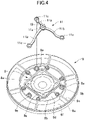
- the speaker 8 is attached to the speaker baffle 9 in a circular shape as a whole in a plan view.
- the speaker baffle 9 includes an outer ring 9a on the outer circumference, an inner ring 9b, and an arm 9c.
- the outer ring 9a is connected to the top of the first duct 4 (see FIG. 6 ).
- the inner ring 9b is spaced inside and concentric with this outer ring 9a.
- the arm 9c connects these outer and inner rings 9a and 9b.
- the outer ring 9a, the inner ring 9b, and the arm 9c define a space serving as a vent 9f.
- a disk-like mounting plate 9d Located inside the inner ring 9b is a disk-like mounting plate 9d that also functions as a front baffle of the speaker 8.
- the mounting plate 9d has a plurality of cylindrical projections 9e at intervals on the outer circumference. These projections 9e are for attaching the error microphone mounting member 11.
- the error microphone mounting member 11 is formed into the shape of a stand.
- the error microphone mounting member 11 includes, at the center, a cylindrical microphone mount 11a with the center at which the error microphone 10 is set.
- the microphone mount 11a includes, on the outer circumference, a plurality of radially extending curved arms 11b each having, at its distal end, an attaching hole 11c into which one of the projections 9e is inserted to attach the error microphone mounting member 11.
- the projections 9e are inserted into the attaching holes 11c to attach or fix the error microphone mounting member 11 to the mounting plate 9d by a mounting means such as an adhesive, ultrasonic welding, or screws.
- the error microphone 10 is placed at a predetermined distance above the speaker 8 by the curved arms 11b protruding upward to lift the error microphone 10.
- the mounting plate 9d includes a rectangular speaker mount 9g corresponding to the shape of the speaker mounting plate 8b, and mounted with the speaker 8 by an appropriate mounting means.
- the top of the back enclosure 7 for the speaker is mounted on the back surface of the mounting plate 9d by an appropriate mounting means.
- the second duct 12 has almost the same outer diameter as the first duct 4.
- the second duct 12 includes first and second connectors 12a and 12b with a large thickness on the bottom and the top, respectively.
- the first connector 12a on the bottom is connected to the top of the outer ring 9a of the speaker baffle 9 by an appropriate attaching means.
- the second connector 12b on the top is connected to a first ring 13a on the bottom of the cylindrical basket 13.
- the cylindrical basket 13 includes the first ring 13a connected to the top of the second duct 12, and a second ring 13b having the same radius as the first ring 13a and spaced above and opposed to the first ring 13a.
- the first and second rings 13a and 13b are connected by a plurality of bar-like connectors 13c extending in the vertical direction.
- the connectors 13c are arranged at intervals as appropriate.
- Interposed between the first and second rings 13a and 13b is a reinforcing ring 13d.
- the number of the reinforcing ring 13d is one in the shown example, but is not limited to one.
- vents 13e Interposed among the first and second rings 13a and 13b, the connectors 13c, and the reinforcing ring 13d, which is provided as necessary, are vents 13e. Through these vents 13e, outside air 20 (see FIG. 14 ) is sucked inside, and controlled sound after the cancellation is emitted.
- the cylindrical basket 13 has an upper opening 13f closed by the duct cover 14.
- the duct cover 14 includes a disk-like top plate 14a, and a cylinder 14b protruding from the inner surface of the top plate 14a and functioning as a wind shield and a reinforcement for the error microphone 10.
- the cylinder 14b has a smaller radius than the top plate 14a.
- the top plate 14a is connected to the second ring 13b of the cylindrical basket 13 to close the upper opening 13f of the cylindrical basket 13.
- the reference microphone mounting member 3 including the reference microphone 2 is attached to the duct base 1.
- the first duct 4 is then connected to the duct base 1.
- the sound absorbing material 5 and the holder 6 are attached to the first duct 4.
- the speaker 8 and the speaker baffle 9 including the back enclosure 7 for the speaker are attached.
- the speaker baffle 9 with the error microphone 10 is connected to the first duct 4.
- the second duct 12 is attached to the speaker baffle 9.
- the cylindrical basket 13 is connected to the second duct 12.
- the duct cover 14 is attached thereon.
- the silencer A is easily assembled simply by sequentially incorporating the parts.
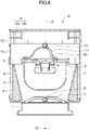
- FIG. 6 is a side sectional view of the assembled silencer A for the air conditioner according to this embodiment.
- the reference microphone 2 detects sound from a noise source 15. While passing through the acoustic path, the noise becomes first plane waves.
- the diaphragm 8a of the speaker 8 emits second plane waves for canceling the first plane waves of the sound detected by the reference microphone 2.
- the reference microphone 2 is as close to the noise source 15 as possible and far from the speaker 8 to some extent. In other words, the distance between the reference microphone 2 and the speaker 8 is set to obtain a time for signal processing.
- the first duct 4 contains the back enclosure 7 for the speaker with a U-shaped side section. Accordingly, the sound waves from the noise source 15 pass between the outer circumferential surface of the back enclosure 7 for the speaker and the inner circumferential surface of the first duct 4. At this time, a narrow acoustic path is formed between the inner circumferential surface of the first duct 4 and the outer circumferential surface of the back enclosure 7 for the speaker to convert the noise into the first plane waves.
- the error microphone 10 that detects the second plane waves from the speaker 8 is spaced apart from the speaker 8 at a distance equal to or longer than a duct diameter.
- the duct diameter is the interval between the inner circumferential surface of the first duct 4 and the outer circumferential surface of the back enclosure 7 for the speaker as will be described later.
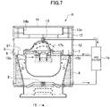
- FIG. 7 illustrates an ANC system 16 connected to the silencer A.
- This ANC system 16 employs feedforward control.
- This type of ANC system 16 is known.
- the ANC system 16 includes the reference microphone 2 for detecting sound, the error microphone 10, and a controller for processing signals from the reference microphone 2 and the error microphone 10.
- the system causes the controller to generate a signal obtained by convolving a transfer function with a signal detected by the reference microphone 2 as a secondary sound source.
- the system updates a filter coefficient so that a signal detected by the error microphone 10 indicates zero to eliminate the sound.
- An example of this circuit will be described later.
- the inner circumferential surface of the first duct 4 and the outer circumferential surface of the back enclosure 7 for the speaker spaced inside and opposed to the first duct 4 function as two walls 18 shown in FIG. 9 , and form a ring-like tube.
- the distance between the two walls 18, which corresponds to a tube diameter D shown in FIG. 10 is set so that noise within a low-frequency range has first plane waves 15b.
- FIG. 8 shows the principle of generating the first plane waves.
- the sound waves from the noise source 15 tend to spread like a circle.
- the walls 18, however, form a tubular acoustic path to reduce the spread so that the waves in the walls 18 are plane waves. That is, substantially plane waves are generated inside the walls 18 as surrounded by the ellipse 19 at the center of FIG. 8 . In this case, the waves with a longer wavelength are flatter.
- reference character 8d on the right denotes a sound source of the speaker 8. Sound with an opposite phase to the noise source 15 cancels the noise.
- the phases of the waves spreading in a circle are indicated by solid and dashed lines which show that the noise source 15 on the left and the sound source 8d on the right have opposite phases.
- the first plane waves 15b propagate in one direction. In general, this state is called a "one-dimensional sound field".
- the first plane waves 15b can be canceled by second plane waves 17b.
- the frequency of the plane waves depends on the tube diameter D of the acoustic path formed by the tubular walls 18, as shown in FIG. 10 .
- a frequency f, a sound speed C, and a diameter D of the acoustic path satisfy the following expression. f ⁇ 0.586 c / D
- the sizes of the inner circumferential surface of the first duct 4 and the opposed outer circumferential surface of the back enclosure 7 for the sound speaker are set so that the noise from the noise source 15 in a low-frequency range from 100 Hz to 1000 Hz has the first plane waves 15b. That is, a high-cut structure is formed to remove a high-frequency component. The high-frequency component is eliminated by the PNC effect using the sound absorbing material 5.
- FIG. 11 shows that the speaker 8 emits cancellation sound 17b for canceling the first plane waves 15b generated in accordance with the tube diameter D as shown in FIG. 10 , using the ANC system 16.
- the cancellation sound 17b corresponds to the second plane waves 17b with an opposite phase to cancel the first plane waves.
- the error microphone 10 detects the sound in the second duct 12 and sends a signal to the ANC system 16 which causes the speaker 8 to emit the second plane waves 17b as the corrected cancellation sound and discharge sound 17c after the cancellation outside at the end.
- FIG. 12 illustrates the sound 17c after cancellation shown in FIG. 11 using the cancellation sound 17b from the speaker 8.
- the cancellation sound 17b is indicated by the thinner line and has an opposite phase to noise 15a indicated by the thicker line.
- FIG. 13 shows an example circuit of the ANC system 16.
- a reference signal x (n) corresponding to noise input to the reference microphone 2 is sent to an FIR filter circuit FIR.
- the FIR filter circuit FIR is connected to an LMS algorithm circuit LMS that receives an error signal e (n) obtained by superimposing a control target signal d (n) detected by the error microphone 10 and a signal z (n) having transfer characteristics between the speaker 8 and the error microphone 10 and reaching a control point.
- the FIR filter circuit FIR has h (k, n) as a filter coefficient vector of an FIR filter.
- Reference character C represents secondary path characteristic, which are transfer characteristics of the acoustic system from the speaker 8 to the error microphone 10.
- C' represents secondary path characteristics, which are transfer characteristics measured in advance.
- the signals are sent from the FIR filter circuit FIR to the speaker 8.
- the arrows mean "variable”.
- the filter is updated so that the error microphone 10 has an acoustic pressure of zero.
- the signal updated to have a most suitable filter coefficient is sent to the speaker 8 to cancel the first plane waves 15b.
- FIG. 14 illustrates flows of intake air and the sound 17c after cancellation in the silencer A for an air conditioner.
- the noise 15a from the noise source 15 such as the fan 102 or the evaporator 104, for example, of the HVAC system is detected by the reference microphone 2 as described above.
- the detection signal is input to and processed by the ANC system 16 as shown in FIG. 7 .
- the noise 15a is converted into the first plane waves 15b in the first duct 4, passes through the vent 9f of the speaker baffle 9, and enters the second duct 12.
- the second duct 12 contains the second plane waves 17b with an opposite phase to the first plane waves 15b from the speaker 8, which cancels the first plane waves 15b.
- a control target signal which is an error signal incompletely eliminated in the second duct 12
- the error microphone 10 is detected by the error microphone 10 and input to the ANC system 16.
- An update signal corrected as appropriate by the ANC system 16 is sent to the speaker 8 which outputs appropriate second plane waves 17b for canceling the first plane waves 15b. Accordingly, the first plane waves 15b are canceled, and the sound 17c after the cancellation is discharged outside though the vents 13e of the cylindrical basket 13.
- the sound 17c after the cancellation is reduced to a level at which the noise 15a is not hard on the ears, as will be described later.
- FIG. 15 shows noise characteristic E of the noise source 15 itself generated when the HVAC is activated.
- the horizontal axis represents the frequency, whereas the vertical axis represents the sound pressure. Noise is generated in a wide frequency range.
- the one-dot chain line F represents silencing characteristics of the silencer A for the air conditioner including the first duct 4 with the speaker unit (i.e., the speaker 8, the speaker baffle 9, and the back enclosure 7), and the duct cover 14, for example, above the fan 102 of the case 100 of the HVAC system, that is, without the sound absorbing material 5.
- the silencer attenuates the sound at a frequency of 1500 Hz and more than 3000 Hz.
- the two-dot chain line G represents silencing characteristics of the silencer A for the air conditioner with built-in sound absorbing material 5 and holder 6.
- the silencer further attenuates the sound at a frequency of 1500 Hz or more.
- the broken line H represents silencing characteristics when the ANC system 16 operates, which reduces noise within a range from 150 Hz to 1000 Hz.
- the sound with a frequency within a range I from 100 Hz to about 1000 Hz is eliminated by the ANC effect.
- the noise hard on the ears from the on-vehicle air conditioner is eliminated by the PNC effect of the sound absorbing material 5.
- the silencer A for an air conditioner according to the present disclosure is applicable not only to a three-row seat vehicle but to other vehicles such as a camping car.
- the silencer A is also applicable in fields other than vehicles.
Abstract
Description
- The present disclosure relates to a silencer for an air conditioner, and more particularly, to a silencer for silencing air-conditioning noise caused by an air conditioner in a vehicle such as an automobile.
- Gasoline engines and diesel engines have been the main drive sources for automobiles. In recent years, hybrid vehicles or electric vehicles including an electric motor as a part of a driving source to reduce greenhouse gas emissions such as carbon dioxide are rapidly spreading as a measure against the global warming.
- Accordingly, hybrid vehicles cause less engine noise, whereas electric vehicles cause no engine noise and bring silence. Other than the noise, there are road noise within a range from 50 Hz to 500 Hz generated when tires roll on a road surface during a travel of an automobile, booming noise of 100 Hz or less caused by cabin resonance, fluid noise generated around side mirrors, and air-conditioning noise of tens of hertz to 10000 Hz generated by air-conditioning of an air conditioner.
- Out of these, the air-conditioning noise is hard on the ears of an occupant.
- In recent years, there is an increasing number of large people, and an increasing number of big families and groups moving in vehicles. There is thus a demand for vehicles, such as minivans, with three-row seats and a wider interior space. In addition to minivans, passenger vehicles with three-row seats are available.
- This type of vehicle includes an air conditioner attached near the rear seats to provide a comfortable space. Once the air conditioner operates, vibrations of a fan sucking outside air and aerodynamic noise of the sucked air are generated over a wide frequency range.
- In a comfortable vehicle with a wider interior space, an occupant tends to enjoy music, videos, and other entertainment. However, noise from the air conditioner near the rear seats are hard on the ears.
- There is a silencer called a "passive noise control (PNC) system" as a noise reduction system made of a sound absorbing material.
- Patent Document 1:
Japanese Unexamined Patent Publication No. H05-172099 - A device according to
Patent Document 1 includes an air intake member made of glass wool in an air flow passage to convert the noise generated at an intake side of a fan into thermal energy in the sound absorbing material and to eliminate noise. Other typical sound absorbing materials include an urethane foam or felt. - Sound absorbing materials eliminate or reduce noise of 1000 Hz or more but fail to eliminate low-frequency noise less than the above frequency.
- The sound absorbing function is determined by the material and amount of a sound absorbing material. In order to increase the sound absorption efficiency, a larger amount of a sound absorbing material is needed. This requires a large structure and a large space and is thus not suitable for reducing the size and weight. In addition, the background art fails to cope with the type and change (e.g., from a lower range to a higher range or in the magnitude) of noise.
- The present disclosure was made in view of the foregoing. It is an objective of the present disclosure to provide a silencer, for an air conditioner, capable of eliminating low-frequency noise and exhibiting desired silencing performance.
- According to
claim 1 of the present disclosure, a silencer is for an air conditioner. The silencer includes: a first duct in a cylindrical shape at a noise outlet, the first duct including a reference microphone that detects noise as a reference signal; a speaker baffle on a top of the first duct, the speaker baffle having a circular shape as whole in a plan view and including a speaker around a center thereof; a back enclosure for the speaker, the back enclosure being on a back surface of the speaker baffle; a second duct that is in a shape of a cylinder and connected to a top of the speaker baffle; an error microphone in the second duct and above a diaphragm of the speaker at a distance to detect a control target signal which is an incompletely eliminated error signal; a cylindrical body for intake connected to a top of the second duct; and a duct cover for closing an upper opening of the cylindrical body. A gap that is between an inner circumferential surface of the first duct and an outer circumferential surface of the back enclosure for the speaker and serves as an acoustic path of noise to provide a plane wave. The noise is in a form of a first plane wave. The error microphone is configured to detect an error signal in the second duct. The speaker is configured to output a second plane wave with a phase opposite to a phase of the first plane wave. - According to
claim 2 of the present disclosure, the silencer further includes: an ANC system connected to the speaker. The reference signal detected by the reference microphone is input to the ANC system connected to the reference microphone. The control target signal of the error microphone is input to the ANC system. An output of the ANC system is applied to the speaker connected. The speaker sends out the second plane wave. - According to
claim 3 of the present disclosure, in the silencer, the acoustic path in the first duct includes a sound absorbing material. - According to
claim 4 of the present disclosure, in the silencer, the duct cover has an inner surface including a cylinder serving as a wind shield and a reinforcement for the error microphone. - According to
claim 5 of the present disclosure, in the silencer, the back enclosure for the speaker has a U-shaped side section. - According to
claim 1 of the present disclosure, the silencer for the air conditioner located at the noise outlet functions as a sound absorbing duct and eliminates even low-frequency noise unable to be eliminated by a typical silencer made of only a sound absorbing material. - According to
claim 2 of the present disclosure, the silencer includes the ANC system that generates a phase opposite to the phase of noise to attenuate the sound pressure of low-frequency noise and further improves the silencing effect. - According to
claim 3 of the present disclosure, the sound absorbing member including, as a main material, the fibers with a high silencing effect is incorporated to eliminate noise over a wide frequency range from a low frequency to 1000 Hz or more. - According to
claim 4 of the present disclosure, the duct cover has a higher rigidity to function as a sound absorbing duct with a higher strength, cause less vibrations, shields the error microphone from wind, and reliably operate the error microphone. - According to
claim 5 of the present disclosure, the speaker has the back enclosure with a U-shaped side section forming an acoustic path, which smoothly guides the air and sound passing through the acoustic path and reduces noise. -
-
FIG. 1 is an exploded perspective view of a silencer for an on-vehicle air conditioner according to an embodiment. -
FIG. 2 is a perspective view of a duct base and a reference microphone mounting member, which are constituent members of the silencer for the on-vehicle air conditioner. -
FIG. 3 is a perspective view of a first duct, a sound absorbing material, a holder for the sound absorbing material, a back enclosure for a speaker, and the speaker, which are constituent members of the silencer for the on-vehicle air conditioner. -
FIG. 4 is a perspective view of a speaker baffle and an error microphone mounting member, which are constituent members of the silencer for the on-vehicle air conditioner according to the embodiment. The error microphone mounting member is attached to this speaker baffle. -
FIG. 5 is a perspective view of a second duct, a cylindrical basket for taking air in and discharging cancellation sound, and a duct cover, which are constituent members of the silencer for the on-vehicle air conditioner according to the embodiment. -
FIG. 6 is a side sectional view of the assembled silencer for the on-vehicle air conditioner according to the present disclosure. -
FIG. 7 illustrates an ANC system connected to the silencer for the on-vehicle air conditioner. -
FIG. 8 illustrates an operation principle of the present disclosure. -
FIG. 9 illustrates the operation principle of the present disclosure. -
FIG. 10 illustrates the operation principle of the present disclosure. -
FIG. 11 illustrates the operation principle of the present disclosure. -
FIG. 12 illustrates a principle of silencing by canceling the phase of noise from a noise source by an ANC system according to the present disclosure. -
FIG. 13 is a block diagram showing an example configuration of the ANC system used in the present disclosure. -
FIG. 14 illustrates an intake flow, the states of first and second plane waves, and a flow of cancellation sound in the silencer for the on-vehicle air conditioner according to the embodiment. -
FIG. 15 shows frequency characteristics of noise from a noise source. The horizontal axis represents the frequency, whereas the vertical axis represents the sound pressure. -
FIG. 16 shows sound absorption (i.e., silencing) characteristics when a back enclosure including a speaker and a speaker baffle is set in the first duct according to the embodiment. -
FIG. 17 illustrates noise reduction characteristics when an ANC system is on. -
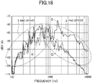
FIG. 18 illustrates ANC and PNC effects of a sound absorbing material in the embodiment. -
FIG. 19 is a schematic perspective view of an on-vehicle air conditioning unit. - Now, a preferred embodiment of the present disclosure will be described with reference to the drawings.
- The present disclosure was made as a measure against noise of a system called a "heating, ventilation, and air conditioning (HVAC) system". This "HVAC system" is a generic term for a module component with air-conditioning functions integrated and is an on-vehicle air conditioner with functional components, such as a heater, a blower, and an air conditioner, integrated.
-
FIG. 19 is a schematic configuration diagram of an HVAC system.Reference character 100 denotes a case of the HVAC system with anupper surface 100a partially including acircular air inlet 101, in the state shown in the figure. Located inside is arotatable fan 102 connected to a motor (not shown). Thefan 102 is a centrifugal blower with a plurality of radial flat blades. - The HVAC includes a
radiator 103 functioning as a heater, anevaporator 104, and ashutter 105, for example. - In an operation, the air sucked into the
case 100 through theair inlet 101 by the rotatingfan 102 is cooled by theevaporator 104 or heated by theradiator 103 as indicated by an arrow, mixed at the degree regulated by theshutter 105, and then discharged through a discharge port. The air discharged from the HVAC system passes through aduct 106 to the foot of a passenger compartment and is sent through anotherduct 107 and an overhead air outlet to the passenger compartment around the rear seats (seats in the second and third rows). - This HVAC is typically located in the interior material and the outer plate next to the seating surface of the seats in the third row. Once the HVAC is activated, the
case 100 and theair inlet 101 emit the wide frequency-range operating noise caused by vibrations and aerodynamic noise. This operating noise passes through the interior material and the gaps between the interior components so as to become considerable noise for an occupant near the seats in the third row. - To address the problem, an HVAC system is attached with a silencer for an air conditioner according to the embodiment of the present disclosure.
-
FIG. 1 is an exploded perspective view of a silencer A for an air conditioner according to the embodiment of the present disclosure. The silencer A employs active noise control (ANC) for a low-frequency range and PNC for a high-frequency range to eliminate noise. - In
FIG. 1 ,reference character 1 denotes a substantially cylindrical duct base attached to the top of acircular air inlet 101 of acase 100 of the HVAC shown inFIG. 19 , and serving a connector.Reference character 2 denotes a reference microphone,reference character 3 denotes a reference microphone mounting member,reference character 4 denotes a first duct in a cylindrical shape,reference character 5 denotes a sound absorbing material set in thefirst duct 4,reference character 6 denotes a holder for thesound absorbing material 5, in the shape of a substantially inverted circular truncated cone,reference character 7 denotes a back enclosure for aspeaker 8,reference character 8 denotes the speaker,reference character 9 denotes a speaker baffle,reference character 10 denotes an error microphone,reference character 11 denotes an error microphone mounting member,reference character 12 denotes a second duct in a cylindrical shape,reference character 13 denotes a cylindrical basket for sucking air, andreference character 14 denotes a duct cover. -
FIG. 2 is a perspective view of theduct base 1, the referencemicrophone mounting member 3 attached to theduct base 1, and thereference microphone 2 mounted on the referencemicrophone mounting member 3. - The
duct base 1 includes: acylindrical body 1a; a flange-like part 1b under thebody 1a, and aflange 1c protruding outward from thebody 1a. Thepart 1b is to be attached to the case of an HVAC system. Thepart 1b is attached to thecase 100 on the outer circumference of thefan 102 shown inFIG. 19 by an appropriate fixing means such as bolts, nuts, ultrasonic welding, or adhesion. - Attached to the upper surface of the
flange 1c by an appropriate fixing means such as adhesion or ultrasonic welding is a referencemicrophone mounting member 3. The referencemicrophone mounting member 3 in the shape of a wheel and includes anannular rim 3a, amicrophone mount 3b, and a plurality ofspokes 3c. Theannular rim 3a is attached to the upper surface of theflange 1c. Themicrophone mount 3b is in a cylindrical shape and located at the center of the referencemicrophone mounting member 3. Thespokes 3c are arranged at intervals in the circumferential direction between the outer circumference of thismicrophone mount 3b and the inner circumference of therim 3a. Thereference microphone 2 is placed at the center of themicrophone mount 3b. Thisreference microphone 2 is to detect the noise generated by the HVAC system. - Extending along the outer circumference of the
flange 1c is a rib-like connector 1d protruding upward. -
FIG. 3 shows thefirst duct 4 in a cylindrical shape, thesound absorbing material 5 in thefirst duct 4 as necessary, theholder 6 for thesound absorbing material 5, theback enclosure 7 of thespeaker 8, and thespeaker 8. - The
first duct 4 includes, at the bottom, aduct connector 4a protruding outward which is inserted into the rib-like connector 1d of theduct base 1 to connect thefirst duct 4 to theduct base 1. - The
sound absorbing material 5 extends along the inner circumferential surface of thefirst duct 4. Thesound absorbing material 5 has a substantially cylindrical shape as a whole, and an inner circumferential surface as a conical taperedsurface 5a. Thetapered surface 5a has an inner radius decreasing from the top to the bottom. This shape is to quickly guide the air from the top to the bottom. Thesound absorbing material 5 includes nanofiber fibers with a high sound absorption coefficient in a high-frequency range in one preferred embodiment. In this embodiment, thesound absorbing material 5 includes nanofiber fibers. - Referring back to
FIG. 3 ,reference character 6 denotes a holder for the sound absorbing material, in the shape of an inverted circular truncated cone. Theholder 6 has an inner radius gradually increasing from the bottom to the top, and includes a plurality ofring members 6a at intervals and a plurality of ring connecting members 6b connecting thering members 6a. Thesound absorbing material 5 is attached and sandwiched between the inner circumferential surface of thefirst duct 4 and theholder 6. The ring connecting members 6b are also arranged at intervals in the circumferential direction. Interposed between thering members 6a and the ring connecting members 6b arewindows 6c to expose thetapered surface 5a of thesound absorbing material 5 and absorb noise. If thesound absorbing material 5 is a molded product bonded and fixed to the inner circumferential surface of thefirst duct 4, theholder 6 may not be provided. - The
back enclosure 7 for the speaker with a U-shaped side section is located around the center of thefirst duct 4. Thespeaker 8 is located at an upper center of thisback enclosure 7 for the speaker.Reference character 8a denotes a diaphragm of the speaker, 8b denotes a speaker mounting plate, andreference character 8c denotes a magnetic circuit. As shown inFIG. 4 , thespeaker 8 is attached to thespeaker baffle 9 in a circular shape as a whole in a plan view. - The
speaker baffle 9 includes anouter ring 9a on the outer circumference, aninner ring 9b, and anarm 9c. Theouter ring 9a is connected to the top of the first duct 4 (seeFIG. 6 ). Theinner ring 9b is spaced inside and concentric with thisouter ring 9a. Thearm 9c connects these outer andinner rings outer ring 9a, theinner ring 9b, and thearm 9c define a space serving as avent 9f. - Located inside the
inner ring 9b is a disk-like mounting plate 9d that also functions as a front baffle of thespeaker 8. The mountingplate 9d has a plurality ofcylindrical projections 9e at intervals on the outer circumference. Theseprojections 9e are for attaching the errormicrophone mounting member 11. - Specifically, the error
microphone mounting member 11 is formed into the shape of a stand. The errormicrophone mounting member 11 includes, at the center, acylindrical microphone mount 11a with the center at which theerror microphone 10 is set. Themicrophone mount 11a includes, on the outer circumference, a plurality of radially extendingcurved arms 11b each having, at its distal end, an attachinghole 11c into which one of theprojections 9e is inserted to attach the errormicrophone mounting member 11. Theprojections 9e are inserted into the attachingholes 11c to attach or fix the errormicrophone mounting member 11 to the mountingplate 9d by a mounting means such as an adhesive, ultrasonic welding, or screws. In this case, theerror microphone 10 is placed at a predetermined distance above thespeaker 8 by thecurved arms 11b protruding upward to lift theerror microphone 10. - The mounting
plate 9d includes arectangular speaker mount 9g corresponding to the shape of thespeaker mounting plate 8b, and mounted with thespeaker 8 by an appropriate mounting means. - The top of the
back enclosure 7 for the speaker is mounted on the back surface of the mountingplate 9d by an appropriate mounting means. - As shown in
FIG. 5 , thesecond duct 12 has almost the same outer diameter as thefirst duct 4. Thesecond duct 12 includes first andsecond connectors first connector 12a on the bottom is connected to the top of theouter ring 9a of thespeaker baffle 9 by an appropriate attaching means. Thesecond connector 12b on the top is connected to afirst ring 13a on the bottom of thecylindrical basket 13. - The
cylindrical basket 13 includes thefirst ring 13a connected to the top of thesecond duct 12, and asecond ring 13b having the same radius as thefirst ring 13a and spaced above and opposed to thefirst ring 13a. The first andsecond rings like connectors 13c extending in the vertical direction. Theconnectors 13c are arranged at intervals as appropriate. Interposed between the first andsecond rings ring 13d. The number of the reinforcingring 13d is one in the shown example, but is not limited to one. Interposed among the first andsecond rings connectors 13c, and the reinforcingring 13d, which is provided as necessary, arevents 13e. Through thesevents 13e, outside air 20 (seeFIG. 14 ) is sucked inside, and controlled sound after the cancellation is emitted. - The
cylindrical basket 13 has anupper opening 13f closed by theduct cover 14. Theduct cover 14 includes a disk-liketop plate 14a, and acylinder 14b protruding from the inner surface of thetop plate 14a and functioning as a wind shield and a reinforcement for theerror microphone 10. Thecylinder 14b has a smaller radius than thetop plate 14a. Thetop plate 14a is connected to thesecond ring 13b of thecylindrical basket 13 to close theupper opening 13f of thecylindrical basket 13. - In assembling the silencer for an air conditioner according to the present embodiment, first, the reference
microphone mounting member 3 including thereference microphone 2 is attached to theduct base 1. Thefirst duct 4 is then connected to theduct base 1. Thesound absorbing material 5 and theholder 6 are attached to thefirst duct 4. In addition, thespeaker 8 and thespeaker baffle 9 including theback enclosure 7 for the speaker are attached. On the other hand, thespeaker baffle 9 with theerror microphone 10 is connected to thefirst duct 4. Thesecond duct 12 is attached to thespeaker baffle 9. Thecylindrical basket 13 is connected to thesecond duct 12. Theduct cover 14 is attached thereon. As a result, the silencer A for the air conditioner with an intake duct structure is assembled. The parts are coaxial with the central axis O (seeFIG. 6 ) of thefirst duct 4. - In this manner, the silencer A is easily assembled simply by sequentially incorporating the parts.
-
FIG. 6 is a side sectional view of the assembled silencer A for the air conditioner according to this embodiment. - In this embodiment, the
reference microphone 2 detects sound from anoise source 15. While passing through the acoustic path, the noise becomes first plane waves. Thediaphragm 8a of thespeaker 8 emits second plane waves for canceling the first plane waves of the sound detected by thereference microphone 2. In this case, thereference microphone 2 is as close to thenoise source 15 as possible and far from thespeaker 8 to some extent. In other words, the distance between thereference microphone 2 and thespeaker 8 is set to obtain a time for signal processing. - The
first duct 4 contains theback enclosure 7 for the speaker with a U-shaped side section. Accordingly, the sound waves from thenoise source 15 pass between the outer circumferential surface of theback enclosure 7 for the speaker and the inner circumferential surface of thefirst duct 4. At this time, a narrow acoustic path is formed between the inner circumferential surface of thefirst duct 4 and the outer circumferential surface of theback enclosure 7 for the speaker to convert the noise into the first plane waves. - The principle of generating plane waves will be described later.
- The
error microphone 10 that detects the second plane waves from thespeaker 8 is spaced apart from thespeaker 8 at a distance equal to or longer than a duct diameter. The duct diameter is the interval between the inner circumferential surface of thefirst duct 4 and the outer circumferential surface of theback enclosure 7 for the speaker as will be described later. -
FIG. 7 illustrates anANC system 16 connected to the silencer A. ThisANC system 16 employs feedforward control. This type ofANC system 16 is known. TheANC system 16 includes thereference microphone 2 for detecting sound, theerror microphone 10, and a controller for processing signals from thereference microphone 2 and theerror microphone 10. In an operation, the system causes the controller to generate a signal obtained by convolving a transfer function with a signal detected by thereference microphone 2 as a secondary sound source. The system then updates a filter coefficient so that a signal detected by theerror microphone 10 indicates zero to eliminate the sound. An example of this circuit will be described later. - In this embodiment, the inner circumferential surface of the
first duct 4 and the outer circumferential surface of theback enclosure 7 for the speaker spaced inside and opposed to thefirst duct 4 function as twowalls 18 shown inFIG. 9 , and form a ring-like tube. The distance between the twowalls 18, which corresponds to a tube diameter D shown inFIG. 10 is set so that noise within a low-frequency range has first plane waves 15b. -
FIG. 8 shows the principle of generating the first plane waves. The sound waves from thenoise source 15 tend to spread like a circle. Thewalls 18, however, form a tubular acoustic path to reduce the spread so that the waves in thewalls 18 are plane waves. That is, substantially plane waves are generated inside thewalls 18 as surrounded by theellipse 19 at the center ofFIG. 8 . In this case, the waves with a longer wavelength are flatter. InFIG. 8 ,reference character 8d on the right denotes a sound source of thespeaker 8. Sound with an opposite phase to thenoise source 15 cancels the noise. The phases of the waves spreading in a circle are indicated by solid and dashed lines which show that thenoise source 15 on the left and thesound source 8d on the right have opposite phases. In the case of plane waves, as shown inFIG. 9 , the first plane waves 15b propagate in one direction. In general, this state is called a "one-dimensional sound field". The first plane waves 15b can be canceled by second plane waves 17b. - The frequency of the plane waves depends on the tube diameter D of the acoustic path formed by the
tubular walls 18, as shown inFIG. 10 . A frequency f, a sound speed C, and a diameter D of the acoustic path satisfy the following expression.
- In this embodiment, the sizes of the inner circumferential surface of the
first duct 4 and the opposed outer circumferential surface of theback enclosure 7 for the sound speaker are set so that the noise from thenoise source 15 in a low-frequency range from 100 Hz to 1000 Hz has the first plane waves 15b. That is, a high-cut structure is formed to remove a high-frequency component. The high-frequency component is eliminated by the PNC effect using thesound absorbing material 5. -
FIG. 11 shows that thespeaker 8 emits cancellation sound 17b for canceling the first plane waves 15b generated in accordance with the tube diameter D as shown inFIG. 10 , using theANC system 16. As shown inFIG. 9 , thecancellation sound 17b corresponds to the second plane waves 17b with an opposite phase to cancel the first plane waves. Theerror microphone 10 detects the sound in thesecond duct 12 and sends a signal to theANC system 16 which causes thespeaker 8 to emit the second plane waves 17b as the corrected cancellation sound and discharge sound 17c after the cancellation outside at the end. -
FIG. 12 illustrates the sound 17c after cancellation shown inFIG. 11 using thecancellation sound 17b from thespeaker 8. Thecancellation sound 17b is indicated by the thinner line and has an opposite phase tonoise 15a indicated by the thicker line. -
FIG. 13 shows an example circuit of theANC system 16. - A reference signal x (n) corresponding to noise input to the
reference microphone 2 is sent to an FIR filter circuit FIR. The FIR filter circuit FIR is connected to an LMS algorithm circuit LMS that receives an error signal e (n) obtained by superimposing a control target signal d (n) detected by theerror microphone 10 and a signal z (n) having transfer characteristics between thespeaker 8 and theerror microphone 10 and reaching a control point. - In the figure, the FIR filter circuit FIR has h (k, n) as a filter coefficient vector of an FIR filter. Reference character C represents secondary path characteristic, which are transfer characteristics of the acoustic system from the
speaker 8 to theerror microphone 10. C' represents secondary path characteristics, which are transfer characteristics measured in advance. The signals are sent from the FIR filter circuit FIR to thespeaker 8. The arrows mean "variable". The filter is updated so that theerror microphone 10 has an acoustic pressure of zero. The signal updated to have a most suitable filter coefficient is sent to thespeaker 8 to cancel the first plane waves 15b. -
FIG. 14 illustrates flows of intake air and the sound 17c after cancellation in the silencer A for an air conditioner. - The
noise 15a from thenoise source 15 such as thefan 102 or theevaporator 104, for example, of the HVAC system is detected by thereference microphone 2 as described above. The detection signal is input to and processed by theANC system 16 as shown inFIG. 7 . - The
noise 15a is converted into the first plane waves 15b in thefirst duct 4, passes through thevent 9f of thespeaker baffle 9, and enters thesecond duct 12. - The
second duct 12 contains the second plane waves 17b with an opposite phase to the first plane waves 15b from thespeaker 8, which cancels the first plane waves 15b. - That is, a control target signal, which is an error signal incompletely eliminated in the
second duct 12, is detected by theerror microphone 10 and input to theANC system 16. An update signal corrected as appropriate by theANC system 16 is sent to thespeaker 8 which outputs appropriate second plane waves 17b for canceling the first plane waves 15b. Accordingly, the first plane waves 15b are canceled, and the sound 17c after the cancellation is discharged outside though thevents 13e of thecylindrical basket 13. - The sound 17c after the cancellation is reduced to a level at which the
noise 15a is not hard on the ears, as will be described later. - Next, a process of reducing noise will be described.
-
FIG. 15 shows noise characteristic E of thenoise source 15 itself generated when the HVAC is activated. The horizontal axis represents the frequency, whereas the vertical axis represents the sound pressure. Noise is generated in a wide frequency range. -
FIG. 16 , the one-dot chain line F represents silencing characteristics of the silencer A for the air conditioner including thefirst duct 4 with the speaker unit (i.e., thespeaker 8, thespeaker baffle 9, and the back enclosure 7), and theduct cover 14, for example, above thefan 102 of thecase 100 of the HVAC system, that is, without thesound absorbing material 5. In this case, the silencer attenuates the sound at a frequency of 1500 Hz and more than 3000 Hz. - The two-dot chain line G represents silencing characteristics of the silencer A for the air conditioner with built-in
sound absorbing material 5 andholder 6. In this case, the silencer further attenuates the sound at a frequency of 1500 Hz or more. - In
FIG. 17 , the broken line H represents silencing characteristics when theANC system 16 operates, which reduces noise within a range from 150 Hz to 1000 Hz. - As described above, as surrounded by the ellipse I in
FIG. 18 , the sound with a frequency within a range I from 100 Hz to about 1000 Hz is eliminated by the ANC effect. As surrounded by then ellipse J, in a frequency range of 1000 Hz or more, the noise hard on the ears from the on-vehicle air conditioner is eliminated by the PNC effect of thesound absorbing material 5. - Note that the silencer A for an air conditioner according to the present disclosure is applicable not only to a three-row seat vehicle but to other vehicles such as a camping car. The silencer A is also applicable in fields other than vehicles.
-
- 1
- Duct Base
- 2
- Reference Microphone
- 3
- Reference Microphone Mounting Member
- 3b
- Microphone Mount
- 4
- First Duct
- 5
- Sound Absorbing Material
- 6
- Holder for Sound Absorbing Material
- 7
- Back Enclosure for Speaker
- 8
- Speaker
- 8d
- Sound Source of Speaker
- 9
- Speaker Baffle
- 9d
- Mounting Plate
- 9f
- Vent
- 10
- Error Microphone
- 11
- Error Microphone Mounting Member
- 11a
- Microphone Mount
- 12
- Second Duct
- 13
- Cylindrical Basket as Intake and Sound Discharge Member
- 13e
- Vent
- 13f
- Upper Opening
- 14
- Duct Cover
- 15
- Noise Source
- 15a
- Noise
- 15b
- First Plane Waves
- 16
- ANC System
- 17b
- Cancellation Sound (Second Plane Waves)
- 17c
- Sound after Cancellation
- 18
- Wall
- 19
- Area Surrounded by Ellipse
- 20
- Outside Air
- 100
- Case
- 101
- Air Inlet
- 102
- Fan
- 103
- Radiator
- 104
- Evaporator
- 105
- Shutter
- 106
- Duct
- 107
- Duct
- HVAC
- On-Vehicle Air Conditioner
- A
- Silencer for Air Conditioner
- E
- Silencing Characteristics of HVAC System in Operation
- F
- Silencing Characteristics When Silencer A for Air Conditioner without Sound Absorbing Material Is Mounted on HVAC System
- G
- Silencing Characteristics When Silencer A for Air Conditioner with Built-In Sound Absorbing Material Is Mounted
- H
- Silencing Characteristics in
Operating ANC System 16 - I
- Silencing Effect of ANC
- J
- Silencing Effect of PNC
Claims (5)
- A silencer for an air conditioner, the silencer characterized by comprising:a first duct in a cylindrical shape at a noise outlet, the first duct including a reference microphone that detects noise as a reference signal;a speaker baffle on a top of the first duct, the speaker baffle having a circular shape as whole in a plan view and including a speaker around a center thereof;a back enclosure for the speaker, the back enclosure being on a back surface of the speaker baffle;a second duct that is in a shape of a cylinder and connected to a top of the speaker baffle;an error microphone in the second duct and above a diaphragm of the speaker at a distance to detect a control target signal that is an incompletely eliminated error signal;a cylindrical body for intake connected to a top of the second duct;a duct cover for closing an upper opening of the cylindrical body; anda gap that is between an inner circumferential surface of the first duct and an outer circumferential surface of the back enclosure for the speaker and serves as an acoustic path of noise to provide a plane wave, the noise being in a form of a first plane wave, the error microphone being configured to detect an error signal in the second duct, the speaker being configured to output a second plane wave with a phase opposite to a phase of the first plane wave.
- The silencer of claim 1, further comprising:an ANC system connected to the speaker, whereinthe reference signal detected by the reference microphone is input to the ANC system connected to the reference microphone,the control target signal of the error microphone is input to the ANC system,an output of the ANC system is applied to the speaker connected, andthe speaker sends out the second plane wave.
- The silencer of claim 1 or 2, wherein
the acoustic path in the first duct includes a sound absorbing material. - The silencer of any one of claims 1 to 3, wherein
the duct cover has an inner surface including a cylinder serving as a wind shield and a reinforcement for the error microphone. - The silencer of any one of claims 1 to 4, wherein
the back enclosure for the speaker has a U-shaped side section.
Applications Claiming Priority (2)
| Application Number | Priority Date | Filing Date | Title |
|---|---|---|---|
| JP2019214979A JP7283715B2 (en) | 2019-11-28 | 2019-11-28 | Silencers for air conditioners |
| PCT/JP2020/036979 WO2021106359A1 (en) | 2019-11-28 | 2020-09-29 | Silent device for air conditioning equipment |
Publications (2)
| Publication Number | Publication Date |
|---|---|
| EP4067771A1 true EP4067771A1 (en) | 2022-10-05 |
| EP4067771A4 EP4067771A4 (en) | 2023-01-11 |
Family
ID=76087193
Family Applications (1)
| Application Number | Title | Priority Date | Filing Date |
|---|---|---|---|
| EP20892965.3A Withdrawn EP4067771A4 (en) | 2019-11-28 | 2020-09-29 | Silent device for air conditioning equipment |
Country Status (5)
| Country | Link |
|---|---|
| US (1) | US11763793B2 (en) |
| EP (1) | EP4067771A4 (en) |
| JP (1) | JP7283715B2 (en) |
| CN (1) | CN114514574A (en) |
| WO (1) | WO2021106359A1 (en) |
Families Citing this family (1)
| Publication number | Priority date | Publication date | Assignee | Title |
|---|---|---|---|---|
| CN117308272B (en) * | 2023-11-28 | 2024-04-09 | 珠海格力电器股份有限公司 | Noise reduction method and device based on air conditioner, air conditioner and computer readable storage medium |
Family Cites Families (11)
| Publication number | Priority date | Publication date | Assignee | Title |
|---|---|---|---|---|
| JP3072171B2 (en) * | 1991-12-25 | 2000-07-31 | 日本ノイズコントロール株式会社 | Air flow guide silencer on fan suction side |
| JPH0798591A (en) * | 1993-09-29 | 1995-04-11 | Fujitsu Ten Ltd | Duct speaker arrangement for canceling noise |
| JPH08272374A (en) * | 1995-03-30 | 1996-10-18 | Daiken Trade & Ind Co Ltd | Active muffler |
| JP5172099B2 (en) | 2006-03-07 | 2013-03-27 | 富士フイルム株式会社 | Planographic printing plate precursor and planographic printing method |
| JP5707722B2 (en) | 2009-03-31 | 2015-04-30 | ダイキン工業株式会社 | Blower |
| WO2014051883A1 (en) | 2012-09-25 | 2014-04-03 | Huntair, Inc. | Methods and systems for active sound attenuation in a fan unit |
| CN104534532B (en) | 2014-12-18 | 2016-09-21 | 宁波方太厨具有限公司 | A kind of denoising device of range hood |
| CN104848432A (en) | 2015-05-29 | 2015-08-19 | 东南大学 | Air purifier with active noise reduction device |
| JP2017083652A (en) * | 2015-10-28 | 2017-05-18 | パナソニックIpマネジメント株式会社 | Sound deadening structure |
| WO2017217270A1 (en) | 2016-06-13 | 2017-12-21 | 株式会社デンソー | Noise reduction device and noise reduction method |
| KR102429335B1 (en) | 2017-12-19 | 2022-08-05 | 한온시스템 주식회사 | Air conditioning system for automotive vehicles |
-
2019
- 2019-11-28 JP JP2019214979A patent/JP7283715B2/en active Active
-
2020
- 2020-09-29 CN CN202080071125.7A patent/CN114514574A/en active Pending
- 2020-09-29 US US17/780,793 patent/US11763793B2/en active Active
- 2020-09-29 WO PCT/JP2020/036979 patent/WO2021106359A1/en unknown
- 2020-09-29 EP EP20892965.3A patent/EP4067771A4/en not_active Withdrawn
Also Published As
| Publication number | Publication date |
|---|---|
| JP2021085370A (en) | 2021-06-03 |
| JP7283715B2 (en) | 2023-05-30 |
| EP4067771A4 (en) | 2023-01-11 |
| US20220415302A1 (en) | 2022-12-29 |
| US11763793B2 (en) | 2023-09-19 |
| CN114514574A (en) | 2022-05-17 |
| WO2021106359A1 (en) | 2021-06-03 |
Similar Documents
| Publication | Publication Date | Title |
|---|---|---|
| US5828759A (en) | System and method for reducing engine noise | |
| CN103574879B (en) | Air-conditioning equipment | |
| EP2492909A1 (en) | Engine sound distribution apparatus for a motor vehicle | |
| CN106340289B (en) | Noise transmission system for a motor vehicle | |
| US20120171942A1 (en) | Ventilation nozzle for a motor vehicle | |
| EP4067771A1 (en) | Silent device for air conditioning equipment | |
| JP2005324771A (en) | Battery cooling system | |
| EP1369576B1 (en) | Integrated engine compartment component and air intake system | |
| JP2012015703A (en) | On-vehicle speaker device | |
| US20180202464A1 (en) | Noise attenuation for systems with blower wheels | |
| WO2020249660A1 (en) | High-performance sound generating system for vehicles | |
| JP2019520724A (en) | Placement of vehicle speakers | |
| US9963083B2 (en) | Vehicle loudspeaker system | |
| JP5499460B2 (en) | Duct and vehicle structure | |
| US20210065674A1 (en) | Vehicular air conditioning system | |
| JP6373159B2 (en) | Intake sound amplifier for internal combustion engine for vehicle | |
| JP3060711B2 (en) | Active noise control device | |
| JP2018111338A (en) | Speaker device of vehicle, and vehicle | |
| CN112193013A (en) | Air duct for vehicle air conditioner, vehicle air conditioner and motor vehicle | |
| EP3451694B1 (en) | Vehicle installation structure comprising a loudspeaker device and ventilation. | |
| EP1162600B1 (en) | Active control of automotive induction noise | |
| KR102309585B1 (en) | Air conditioning system for automotive vehicles | |
| JP2004004298A (en) | Noise controller and air-conditioning machine | |
| JPH0893583A (en) | Intake structure of engine | |
| JP2004132203A (en) | Soundproof structure of engine room |
Legal Events
| Date | Code | Title | Description |
|---|---|---|---|
| STAA | Information on the status of an ep patent application or granted ep patent |
Free format text: STATUS: THE INTERNATIONAL PUBLICATION HAS BEEN MADE |
|
| PUAI | Public reference made under article 153(3) epc to a published international application that has entered the european phase |
Free format text: ORIGINAL CODE: 0009012 |
|
| STAA | Information on the status of an ep patent application or granted ep patent |
Free format text: STATUS: REQUEST FOR EXAMINATION WAS MADE |
|
| 17P | Request for examination filed |
Effective date: 20220624 |
|
| AK | Designated contracting states |
Kind code of ref document: A1 Designated state(s): AL AT BE BG CH CY CZ DE DK EE ES FI FR GB GR HR HU IE IS IT LI LT LU LV MC MK MT NL NO PL PT RO RS SE SI SK SM TR |
|
| A4 | Supplementary search report drawn up and despatched |
Effective date: 20221213 |
|
| RIC1 | Information provided on ipc code assigned before grant |
Ipc: F24F 130/40 20180101ALI20221207BHEP Ipc: F04D 29/66 20060101ALI20221207BHEP Ipc: G10K 11/178 20060101ALI20221207BHEP Ipc: G10K 11/16 20060101ALI20221207BHEP Ipc: F24F 13/24 20060101ALI20221207BHEP Ipc: F24F 13/02 20060101AFI20221207BHEP |
|
| DAV | Request for validation of the european patent (deleted) | ||
| DAX | Request for extension of the european patent (deleted) | ||
| GRAP | Despatch of communication of intention to grant a patent |
Free format text: ORIGINAL CODE: EPIDOSNIGR1 |
|
| RIC1 | Information provided on ipc code assigned before grant |
Ipc: F24F 130/40 20180101ALI20230526BHEP Ipc: H04R 1/10 20060101ALI20230526BHEP Ipc: H04R 1/02 20060101ALI20230526BHEP Ipc: B60H 1/00 20060101ALI20230526BHEP Ipc: F24F 13/24 20060101ALI20230526BHEP Ipc: G10K 11/16 20060101ALI20230526BHEP Ipc: G10K 11/178 20060101ALI20230526BHEP Ipc: F04D 29/66 20060101ALI20230526BHEP Ipc: F24F 13/02 20060101AFI20230526BHEP |
|
| STAA | Information on the status of an ep patent application or granted ep patent |
Free format text: STATUS: GRANT OF PATENT IS INTENDED |
|
| INTG | Intention to grant announced |
Effective date: 20230706 |
|
| STAA | Information on the status of an ep patent application or granted ep patent |
Free format text: STATUS: THE APPLICATION IS DEEMED TO BE WITHDRAWN |
|
| 18D | Application deemed to be withdrawn |
Effective date: 20231117 |