EP4067660A1 - Scroll compressor - Google Patents
Scroll compressor Download PDFInfo
- Publication number
- EP4067660A1 EP4067660A1 EP20893617.9A EP20893617A EP4067660A1 EP 4067660 A1 EP4067660 A1 EP 4067660A1 EP 20893617 A EP20893617 A EP 20893617A EP 4067660 A1 EP4067660 A1 EP 4067660A1
- Authority
- EP
- European Patent Office
- Prior art keywords
- motor
- scroll compressor
- rotation axis
- outgoing line
- rotor
- Prior art date
- Legal status (The legal status is an assumption and is not a legal conclusion. Google has not performed a legal analysis and makes no representation as to the accuracy of the status listed.)
- Granted
Links
Images




Classifications
-
- F—MECHANICAL ENGINEERING; LIGHTING; HEATING; WEAPONS; BLASTING
- F04—POSITIVE - DISPLACEMENT MACHINES FOR LIQUIDS; PUMPS FOR LIQUIDS OR ELASTIC FLUIDS
- F04C—ROTARY-PISTON, OR OSCILLATING-PISTON, POSITIVE-DISPLACEMENT MACHINES FOR LIQUIDS; ROTARY-PISTON, OR OSCILLATING-PISTON, POSITIVE-DISPLACEMENT PUMPS
- F04C18/00—Rotary-piston pumps specially adapted for elastic fluids
- F04C18/02—Rotary-piston pumps specially adapted for elastic fluids of arcuate-engagement type, i.e. with circular translatory movement of co-operating members, each member having the same number of teeth or tooth-equivalents
- F04C18/0207—Rotary-piston pumps specially adapted for elastic fluids of arcuate-engagement type, i.e. with circular translatory movement of co-operating members, each member having the same number of teeth or tooth-equivalents both members having co-operating elements in spiral form
- F04C18/0215—Rotary-piston pumps specially adapted for elastic fluids of arcuate-engagement type, i.e. with circular translatory movement of co-operating members, each member having the same number of teeth or tooth-equivalents both members having co-operating elements in spiral form where only one member is moving
-
- F—MECHANICAL ENGINEERING; LIGHTING; HEATING; WEAPONS; BLASTING
- F04—POSITIVE - DISPLACEMENT MACHINES FOR LIQUIDS; PUMPS FOR LIQUIDS OR ELASTIC FLUIDS
- F04C—ROTARY-PISTON, OR OSCILLATING-PISTON, POSITIVE-DISPLACEMENT MACHINES FOR LIQUIDS; ROTARY-PISTON, OR OSCILLATING-PISTON, POSITIVE-DISPLACEMENT PUMPS
- F04C23/00—Combinations of two or more pumps, each being of rotary-piston or oscillating-piston type, specially adapted for elastic fluids; Pumping installations specially adapted for elastic fluids; Multi-stage pumps specially adapted for elastic fluids
- F04C23/008—Hermetic pumps
-
- F—MECHANICAL ENGINEERING; LIGHTING; HEATING; WEAPONS; BLASTING
- F04—POSITIVE - DISPLACEMENT MACHINES FOR LIQUIDS; PUMPS FOR LIQUIDS OR ELASTIC FLUIDS
- F04C—ROTARY-PISTON, OR OSCILLATING-PISTON, POSITIVE-DISPLACEMENT MACHINES FOR LIQUIDS; ROTARY-PISTON, OR OSCILLATING-PISTON, POSITIVE-DISPLACEMENT PUMPS
- F04C29/00—Component parts, details or accessories of pumps or pumping installations, not provided for in groups F04C18/00 - F04C28/00
- F04C29/0042—Driving elements, brakes, couplings, transmissions specially adapted for pumps
- F04C29/0085—Prime movers
-
- F—MECHANICAL ENGINEERING; LIGHTING; HEATING; WEAPONS; BLASTING
- F04—POSITIVE - DISPLACEMENT MACHINES FOR LIQUIDS; PUMPS FOR LIQUIDS OR ELASTIC FLUIDS
- F04C—ROTARY-PISTON, OR OSCILLATING-PISTON, POSITIVE-DISPLACEMENT MACHINES FOR LIQUIDS; ROTARY-PISTON, OR OSCILLATING-PISTON, POSITIVE-DISPLACEMENT PUMPS
- F04C29/00—Component parts, details or accessories of pumps or pumping installations, not provided for in groups F04C18/00 - F04C28/00
- F04C29/02—Lubrication; Lubricant separation
-
- H—ELECTRICITY
- H02—GENERATION; CONVERSION OR DISTRIBUTION OF ELECTRIC POWER
- H02K—DYNAMO-ELECTRIC MACHINES
- H02K1/00—Details of the magnetic circuit
- H02K1/06—Details of the magnetic circuit characterised by the shape, form or construction
- H02K1/12—Stationary parts of the magnetic circuit
- H02K1/16—Stator cores with slots for windings
-
- H—ELECTRICITY
- H02—GENERATION; CONVERSION OR DISTRIBUTION OF ELECTRIC POWER
- H02K—DYNAMO-ELECTRIC MACHINES
- H02K1/00—Details of the magnetic circuit
- H02K1/06—Details of the magnetic circuit characterised by the shape, form or construction
- H02K1/12—Stationary parts of the magnetic circuit
- H02K1/18—Means for mounting or fastening magnetic stationary parts on to, or to, the stator structures
- H02K1/185—Means for mounting or fastening magnetic stationary parts on to, or to, the stator structures to outer stators
-
- F—MECHANICAL ENGINEERING; LIGHTING; HEATING; WEAPONS; BLASTING
- F04—POSITIVE - DISPLACEMENT MACHINES FOR LIQUIDS; PUMPS FOR LIQUIDS OR ELASTIC FLUIDS
- F04C—ROTARY-PISTON, OR OSCILLATING-PISTON, POSITIVE-DISPLACEMENT MACHINES FOR LIQUIDS; ROTARY-PISTON, OR OSCILLATING-PISTON, POSITIVE-DISPLACEMENT PUMPS
- F04C2210/00—Fluid
- F04C2210/26—Refrigerants with particular properties, e.g. HFC-134a
-
- F—MECHANICAL ENGINEERING; LIGHTING; HEATING; WEAPONS; BLASTING
- F04—POSITIVE - DISPLACEMENT MACHINES FOR LIQUIDS; PUMPS FOR LIQUIDS OR ELASTIC FLUIDS
- F04C—ROTARY-PISTON, OR OSCILLATING-PISTON, POSITIVE-DISPLACEMENT MACHINES FOR LIQUIDS; ROTARY-PISTON, OR OSCILLATING-PISTON, POSITIVE-DISPLACEMENT PUMPS
- F04C2240/00—Components
- F04C2240/30—Casings or housings
-
- F—MECHANICAL ENGINEERING; LIGHTING; HEATING; WEAPONS; BLASTING
- F04—POSITIVE - DISPLACEMENT MACHINES FOR LIQUIDS; PUMPS FOR LIQUIDS OR ELASTIC FLUIDS
- F04C—ROTARY-PISTON, OR OSCILLATING-PISTON, POSITIVE-DISPLACEMENT MACHINES FOR LIQUIDS; ROTARY-PISTON, OR OSCILLATING-PISTON, POSITIVE-DISPLACEMENT PUMPS
- F04C2240/00—Components
- F04C2240/40—Electric motor
-
- F—MECHANICAL ENGINEERING; LIGHTING; HEATING; WEAPONS; BLASTING
- F04—POSITIVE - DISPLACEMENT MACHINES FOR LIQUIDS; PUMPS FOR LIQUIDS OR ELASTIC FLUIDS
- F04C—ROTARY-PISTON, OR OSCILLATING-PISTON, POSITIVE-DISPLACEMENT MACHINES FOR LIQUIDS; ROTARY-PISTON, OR OSCILLATING-PISTON, POSITIVE-DISPLACEMENT PUMPS
- F04C2240/00—Components
- F04C2240/60—Shafts
-
- F—MECHANICAL ENGINEERING; LIGHTING; HEATING; WEAPONS; BLASTING
- F04—POSITIVE - DISPLACEMENT MACHINES FOR LIQUIDS; PUMPS FOR LIQUIDS OR ELASTIC FLUIDS
- F04C—ROTARY-PISTON, OR OSCILLATING-PISTON, POSITIVE-DISPLACEMENT MACHINES FOR LIQUIDS; ROTARY-PISTON, OR OSCILLATING-PISTON, POSITIVE-DISPLACEMENT PUMPS
- F04C2240/00—Components
- F04C2240/80—Other components
- F04C2240/803—Electric connectors or cables; Fittings therefor
Definitions
- the present disclosure relates to a scroll compressor.
- Patent Literature 1 JP 2003-286949 A
- a scroll compressor that guides part of a refrigerant discharged from a compression mechanism from space above the motor to space below the motor to cool a motor,.
- the refrigerant that has flowed into the space below the motor turns around in the space below the motor and flows into the space above the motor again, and finally flows out to the outside of the scroll compressor through a discharge pipe.
- a scroll compressor includes a scroll compression mechanism, a motor, and a casing.
- the scroll compression mechanism compresses a refrigerant.
- the motor drives the scroll compression mechanism.
- the casing houses the scroll compression mechanism and the motor.
- the motor includes a stator, a rotor, a coil, and an outgoing line.
- the stator includes a stator core and an insulator.
- the rotor is disposed inside the stator.
- the coil is wound around a plurality of teeth of the stator core via the insulator.
- the outgoing line is provided at an end of the coil.
- an outer radius of the teeth centered on a position of the rotation axis of the rotor is D1 and an inner radius of the teeth centered on a position of the rotation axis of the rotor is D2, and that an average distance from the position of the rotation axis of the rotor to the outgoing line and/or a film wound around the outgoing line is da.
- the outgoing line and/or the film wound around the outgoing line is disposed to satisfy the relationship of 0.65 ⁇ (D1 - da)/(D1 - D2) ⁇ 0.95.
- the outgoing line and/or the film wound around the outgoing line is disposed to satisfy the above-described formula, and the end face of the stator is covered to some extent. As a result, it is possible to inhibit oil from moving together with the refrigerant passing through a gap between the coils and being carried out in large quantities to the outside of the scroll compressor.
- the scroll compressor according to a second aspect is the scroll compressor according to the first aspect, in which in a region of at least 95% or more of a circumferential direction centered on the position of the rotation axis, the outgoing line and/or the film wound around the outgoing line is disposed to satisfy a relationship of 0.65 ⁇ (D1 - d)/(D1 - D2) ⁇ 0.95.
- d is the distance from the position of the rotation axis of the rotor to the outgoing line and/or the film wound around the outgoing line.
- the outgoing line and/or the film wound around the outgoing line is disposed to satisfy the above-described formula in the region of 95% or more of the circumferential direction. This makes it particularly easy to inhibit the oil from moving together with the refrigerant passing through the gap between the coils and being carried out in large quantities to the outside of the scroll compressor.
- the scroll compressor according to a third aspect is the scroll compressor according to the first aspect or the second aspect, in which a gap between the outgoing line and the coil is 2 mm or more in a rotation axis direction of the rotor.
- this scroll compressor can reduce the total amount of oil that has moved together with the refrigerant in the gap between the coils from flowing directly into the space between the motor and the scroll compression mechanism and flowing out of the scroll compressor.
- the scroll compressor according a fourth aspect is the scroll compressor according to any one of the first aspect to the third aspect, in which an opening of 17% or more and less than 40% is formed in an outer wall of the insulator disposed to surround the outgoing line.
- the scroll compressor of the fourth aspect at least part of the refrigerant that has passed through the gap between the coils passes through the opening of the outer wall of the insulator and heads for the inner peripheral surface of the casing, colliding with the inner peripheral surface of the casing. Therefore, the outflow of oil to the outside of the scroll compressor is more easily reduced than when the refrigerant that has passed through the gap between the coils heads directly for the outside of the scroll compressor. Since the proportion of the opening to the outer wall of the insulator is less than 40%, the required strength of the outer wall of the insulator can also be maintained.
- the scroll compressor according to a fifth aspect is the scroll compressor according to any one of the first aspect to the fourth aspect, further including a guide.
- the guide guides the refrigerant discharged by the scroll compression mechanism into the space above the motor to the space below the motor.
- the film wound around the outgoing line is disposed at least on the opposite side of the guide across the rotation axis.
- the film is disposed at least in the region on the opposite side of the guide where the flow velocity of the refrigerant is likely to become particularly large. Therefore it is possible to inhibit the oil from moving together with the refrigerant passing through the gap between the coils and being carried out in large quantities to the outside of the scroll compressor.
- the scroll compressor according to a sixth aspect is the scroll compressor according to any one of the first aspect to the fifth aspect, in which the motor is a motor of concentrated winding.
- a scroll compressor 10 according to one embodiment will be described with reference to the drawings. Note that in order to avoid making the drawings difficult to see, part of reference signs may be omitted in the drawings.
- FIG. 1 is a schematic longitudinal cross-sectional view of the scroll compressor 10.
- the scroll compressor 10 is used for a refrigeration cycle apparatus such as an air conditioner, and constitutes part of a refrigerant circuit of the refrigeration cycle apparatus.
- the scroll compressor 10 takes in and compresses a low-pressure refrigerant in a refrigeration cycle, and discharges a high-pressure refrigerant in the refrigeration cycle to the refrigerant circuit.
- the scroll compressor 10 mainly includes a casing 20, a compression mechanism 30, a motor 40, a crank shaft 80, and a lower bearing 90, as shown in FIG. 1 .
- the motor 40 is disposed in a high-pressure space into which a high-pressure refrigerant gas discharged by the compression mechanism 30 flows.
- the scroll compressor 10 is a high-pressure dome-type scroll compressor.
- the casing 20 includes a body 21, an upper lid 22a, and a lower lid 22b, as shown in FIG. 1 .
- the body 21 is a cylindrical member with upper and lower openings.
- the upper lid 22a is provided at the upper end of the body 21.
- the lower lid 22b is provided at the lower end of the body 21.
- the body 21, the upper lid 22a, and the lower lid 22b are fixed by welding so as to maintain airtightness.
- the casing 20 houses components of the scroll compressor 10 therein, including the compression mechanism 30, the motor 40, the crank shaft 80, and the lower bearing 90, as shown in FIG. 1 .
- An upper part of the casing 20 is provided with an intake pipe 23 that penetrates the upper lid 22a of the casing 20, as shown in FIG. 1 .
- the intake pipe 23 is a pipe that supplies a low-pressure gas refrigerant to be compressed by the compression mechanism 30 from a refrigerant circuit to which the scroll compressor 10 is connected.
- the intake pipe 23 is airtightly attached to the upper lid 22a.
- the lower end of the intake pipe 23 is connected to a fixed scroll 31 of the compression mechanism 30, which will be described later.
- the intake pipe 23 communicates with a compression chamber Sc of the compression mechanism 30.
- a discharge pipe 24 is provided in an up-and-down middle portion of the body 21 of the casing 20 as shown in FIG. 1 .
- a high-pressure gas refrigerant compressed by the scroll compressor 10 is discharged to the discharge pipe 24.
- the discharge pipe 24 is airtightly attached to the body 21.
- the end of the discharge pipe 24 within the casing 20 is disposed in a first space S1 between a housing 33 of the compression mechanism 30, which will be described later, and the motor 40.
- An oil reservoir space 25 is formed in the lower part of the casing 20.
- the oil reservoir space 25 stores an oil L (refrigerating machine oil) for lubricating a sliding portion of the compression mechanism 30 and the crank shaft 80.
- the oil L in the oil reservoir space 25 passes through an oil supply path 84 formed inside the crank shaft 80 and is supplied to the sliding portion of the compression mechanism 30 and the crank shaft 80.
- Part of the oil L that has lubricated the compression mechanism 30 and the crank shaft 80 passes through a gap formed between a stator 50 of the motor 40, which will be described later, and the body 21, and returns to the oil reservoir space 25 below the casing 20.
- the compression mechanism 30 is one example of the scroll compression mechanism that compresses the refrigerant.
- the compression mechanism 30 mainly includes the fixed scroll 31, a movable scroll 32, and the housing 33, as shown in FIG. 1 .
- the fixed scroll 31 is disposed above the housing 33, as shown in FIG. 1 .
- the fixed scroll 31 is disposed in close contact with the housing 33.
- the movable scroll 32 is disposed between the fixed scroll 31 and the housing 33, as shown in FIG. 1 .
- the housing 33 supports the movable scroll 32 from below.
- the fixed scroll 31 and the movable scroll 32 are disposed with a lower surface of an end plate 31a of the fixed scroll 31 and an upper surface of an end plate 32a of the movable scroll 32 facing each other.
- the compression mechanism 30 combines a spiral (involute) fixed-side wrap 31b protruding downward from the lower surface of the end plate 31a of the fixed scroll 31, and a spiral (involute) movable-side wrap 32b protruding upward from the upper surface of the end plate 32a of the movable scroll 32 to form the compression chamber Sc between the adjacent fixed-side wrap 31b and movable-side wrap 32b.
- the movable scroll 32 is provided with a boss part 32c below the end plate 32a.
- the movable scroll 32 is coupled with the crank shaft 80 by inserting an eccentric part 81 of the crank shaft 80, which will be described later, into the boss part 32c.
- the crank shaft 80 is coupled with a rotor 60 of the motor 40, as will be described later.
- the motor 40 is driven and the crank shaft 80 coupled with the rotor 60 rotates, the movable scroll 32 revolves with respect to the fixed scroll 31 without rotating by the work of an Oldham ring 34 disposed between the movable scroll 32 and the housing 33.
- the movable scroll 32 turns around, thereby compressing the refrigerant in the compression chamber Sc.
- the refrigerant compressed in the compression chamber Sc is discharged upward from a discharge port 31c formed in the end plate 31a of the fixed scroll 31.
- the refrigerant discharged from the discharge port 31c passes through a refrigerant passage 31d formed in the fixed scroll 31 and a refrigerant passage 33b formed in the housing 33, flowing into the first space S1 below the housing 33.
- the housing 33 is fixed to the body 21 of the casing 20.
- the fixing method is not limited, the housing 33 is press-fitted into the body 21 of the casing 20, and the entire circumference of the outer peripheral surface of the housing 33 is airtightly fixed to an inner peripheral surface 21a of the body 21.
- the fixed scroll 31 is closely fixed to the upper surface of the housing 33.
- a concave portion 33a recessed downward is formed in the center of the upper portion of the housing 33.
- the boss part 32c of the movable scroll 32 with which the eccentric part 81 of the crank shaft 80 is coupled is disposed in the concave portion 33a.
- An upper bearing 35 that pivotally supports the crank shaft 80 is provided below the housing 33.
- the upper bearing 35 rotatably supports a main shaft 82 of the crank shaft 80, which will be described later.
- FIG. 2 is a schematic cross-sectional view taken along the line II-II of the scroll compressor 10 of FIG. 1 .
- FIG. 2 schematically illustrates coils 42 wound around teeth 524 of a stator core 52, which will be described later.
- FIG. 3 is a schematic plan view of the motor 40 when the motor 40 is viewed from above.
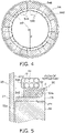
- FIG. 4 is a schematic plan view schematically showing a disposition state of outgoing lines 70 disposed above an insulator 54.
- FIG. 5 is a schematic longitudinal cross-sectional view schematically showing the attachment state of the outgoing lines 70 to the stator 50.
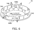
- FIG. 6 is a schematic perspective view schematically showing the insulator 54. To avoid complicated drawing, FIG. 6 depicts the insulator 54 with illustration of some components omitted.
- the motor 40 is a drive unit that drives the compression mechanism 30.
- the motor 40 is disposed below the compression mechanism 30. Specifically, as shown in FIG. 1 , the motor 40 is disposed between the upper bearing 35 provided in the housing 33 of the compression mechanism 30 and the lower bearing 90.
- the first space S1 where the end of the discharge pipe 24 is disposed, is formed between the motor 40 and the housing 33.
- the motor 40 mainly includes the stator 50, the coils 42, the rotor 60, and the outgoing lines 70, as shown in FIG. 1 .
- the stator 50 is formed in a cylindrical shape.
- the rotor 60 is disposed via a small gap (air gap G) in the interior (hollow portion) of the stator 50, as shown in FIG. 1 .
- the stator 50 mainly includes the stator core 52 and the insulator 54, as shown in FIG. 5 .
- the insulator 54 is disposed at both ends of the stator core 52 in the axial direction of the crank shaft 80 (hereinafter, simply referred to as axial direction).
- the stator core 52 is formed by, for example, laminating a plurality of magnetic steel sheets.
- the stator core 52 is formed in a substantially cylindrical shape.
- the stator core 52 is fixed to the inner peripheral surface 21a of the body 21 of the casing 20. Although the fixing method is not limited, the stator core 52 is press-fitted into the body 21 of the casing 20.
- the stator core 52 includes an annular yoke 522 and the plurality of teeth 524, as shown in FIG. 2 .
- Each of the teeth 524 protrudes radially inward from the inner peripheral surface of the yoke 522.
- the plurality of teeth 524 is arranged on the yoke 522 at equal intervals in the circumferential direction.
- the stator core 52 includes 12 teeth 524 as shown in FIG. 2 .
- the number of teeth of the scroll compressor of the present disclosure is not limited to 12.
- a core cut 52a cut out so as to be recessed toward the center in the radial direction is formed on part of the outer peripheral surface of the circular shape of the yoke 522. This forms a gap between the core cut 52a and the body 21.
- the coils 42 are wound around the plurality of teeth 524 via the insulator 54. Each of the coils 42 is wound around the single tooth 524, not across the plurality of teeth 524.
- the motor 40 is a motor of concentrated winding. There is a gap 42a between the coil 42 wound around each tooth 524 and the coil 42 wound around the tooth 524 adjacent to the above-described tooth 524, as shown in FIG. 2 .
- the insulator 54 is attached to the upper and lower ends of the stator core 52 as shown in FIG. 1 .
- the insulator 54 is provided in order to insulate the stator core 52 from the coil 42.
- the insulator 54 mainly includes an annular part 542, a plurality of tooth parts 544, a first wall 546, and a second wall 548, as shown in FIG. 6 .
- the annular part 542 is provided at a position corresponding to the yoke 522 of the stator core 52. In other words, the annular part 542 is provided adjacent to the yoke 522 of the stator core 52 in the axial direction.
- Each tooth part 544 protrudes radially inward from the inner peripheral surface of the annular part 542.
- the plurality of tooth parts 544 is arranged on the annular part 542 at equal intervals in the circumferential direction.
- the plurality of tooth parts 544 is provided at positions corresponding to the teeth 524 of the stator core 52.
- each of the plurality of tooth parts 544 is provided adjacent to corresponding one of the teeth 524 of the stator core 52.
- the first wall 546 is provided at the inner end of each tooth part 544 and extends on the opposite side of the stator core 52 in the axial direction.
- the second wall 548 extends on the opposite side of the stator core 52 from the end face of the annular part 542 in the axial direction.
- the second wall 548 is formed in a substantially cylindrical shape in plan view.
- the second wall 548 of the insulator 54 disposed above the stator core 52 is provided with a plurality of openings 548a.
- the openings 548a here include both through holes and cutouts provided on the second wall 548.
- Part of the openings 548a is used for position adjustment of the outgoing lines 70.
- the outgoing lines 70 are sandwiched and held by the second wall 548 adjacent to the opening 548a.
- part of the openings 548a is used as a mounting part for a fixture 74 of the outgoing lines 70.
- At least part of the openings 548a is used to guide the refrigerant gas rising from the space below the motor 40 through the gap 42a between the coils 42 to the inner peripheral surface 21a of the body 21 of the casing 20, as will be described later.
- the rotor 60 is rotatably housed in the hollow portion of the stator 50.
- a central hole 62 for inserting the main shaft 82 of the crank shaft 80 is formed in the central part of the rotor 60 (see FIG. 1 ).
- the main shaft 82 is inserted into the central hole 62 of the rotor 60 and the rotor 60 is fixed to the main shaft 82, whereby the rotor 60 is coupled with the movable scroll 32 via the crank shaft 80.
- a plurality of permanent magnets (not shown) is embedded in the rotor 60.
- Supply of a current to the coil 42 of the stator 50 generates a rotating magnetic field.
- the rotor 60 rotates around a rotation axis O because the permanent magnet provided in the rotor 60 is affected by the rotating magnetic field, and causes the movable scroll 32, which is coupled via the crank shaft 80, to rotate.
- the rotation axis O of the rotor 60 and the rotation axis of the crank shaft 80 align.
- the motor 40 includes the plurality of outgoing lines 70.
- Each outgoing line 70 is provided at an end of each coil 42 wound around each tooth 524 of the stator core 52.
- the outgoing line 70 is a lead wire that connects the coil 42 to a terminal (not shown) for supplying electric power to the coil 42. Electric power is supplied to the coils 42 via the outgoing lines 70.
- the outgoing lines 70 are disposed above the motor 40 and above the coils 42 wound around the teeth 524 of the stator core 52 via the insulator 54 (see FIGS. 1 and 3 ).
- a film 72 made of an insulating material may be wound around the outgoing lines 70 so as to hold the plurality of outgoing lines 70 together.
- the film 72 is made of, for example, resin.
- the film 72 may be wound around part of the outgoing lines 70, or may be wound around the entire outgoing lines 70.
- the film 72 wound around the outgoing lines 70 is disposed in a predetermined region of the circumferential direction in plan view.
- the position where the film 72 is preferably disposed will be described later. Note that the film 72 may not be used in the motor 40.
- an outer radius of the teeth 524 of the stator core 52 centered on the position of the rotation axis O of the rotor 60 is represented as symbol D1
- an inner radius of the teeth 524 centered on the position of the rotation axis O is represented as symbol D2.
- the outer radius D1 of the teeth 524 when the motor 40 is viewed along the rotation axis O specifically means the distance between the rotation axis O and a connection portion between the yoke 522 and the teeth 524 in plan view (see FIG. 2 ).
- the inner radius D2 of the teeth 524 when the motor 40 is viewed along the rotation axis O specifically means the distance between the rotation axis O and an inner peripheral end of the teeth 524 (minimum distance) in plan view (see FIG. 2 ).
- the distance from the position of the rotation axis O of the rotor 60 to the outgoing lines 70 or the film 72 when the motor 40 is viewed along the rotation axis O of the rotor 60 is represented as symbol d (see FIG. 4 ).
- the distance from the rotation axis O to the outgoing lines 70 and the film 72 wound around the outgoing lines 70 is represented as symbol d in plan view. Note that in the motor 40, the distance (shortest distance) between the rotation axis O and the outgoing lines 70 or the film 72 in plan view does not have to be constant.
- the distance between the rotation axis O and the outgoing lines 70 or the film 72 being not constant in plan view means that the distance d between the rotation axis O and the outgoing lines 70 or the film 72 (shortest distance from the position of the rotation axis O to the outgoing lines 70 or the film 72) differs depending on the position in the circumferential direction.
- the average distance from the position of the rotation axis O of the rotor 60 to the outgoing lines 70 and the film 72 wound around the outgoing lines 70 when the motor 40 is viewed along the rotation axis O of the rotor 60 is represented as symbol da (see the two-dot chain line in FIG. 4 ).
- the average distance from the rotation axis O to the outgoing lines 70 and the film 72 wound around the outgoing lines 70 in plan view is represented as symbol da.
- the outgoing lines 70 and the film 72 wound around the outgoing lines 70 are disposed so as to satisfy the relationship of 0.65 ⁇ D 1 ⁇ da / D 1 ⁇ D 2 ⁇ 0.95
- the area surrounded by a circle having the radius da (0.05D1 + 0.95D2 ⁇ da ⁇ 0.35D1 + 0.65D2) centered on the rotation axis O and a circle having the outer radius D1 centered on the rotation axis O is generally covered with the outgoing lines 70 or the film 72.
- the value of (D1 - da)/(D1 - D2) may be referred to as an average stator end face coverage rate in the following description.
- the outgoing lines 70 and the film 72 wound around the outgoing lines 70 are disposed to satisfy the relationship of 0.65 ⁇ D 1 ⁇ d / D 1 ⁇ D 2 ⁇ 0.95
- the scroll compressor 10 of the present disclosure when the motor 40 is viewed along the rotation axis O of the rotor 60, in the region of 95% or more of the circumferential direction, the area surrounded by the circle having the radius d (0.05D1 + 0.95D2 ⁇ d ⁇ 0.35D1 + 0.65D2) centered on the rotation axis O and the circle having the outer radius D1 centered on the rotation axis O is largely covered with the outgoing lines 70 or the film 72.
- the value of (D1 - d)/(D1 - D2) may be referred to as a stator end face coverage
- the outgoing lines 70 and the film 72 are disposed so as to satisfy the relationship of Formula 2 in the entire region of the circumferential direction centered on the position of the rotation axis O.
- FIG. 7 is experimental data, in the scroll compressor 10, showing a change in the amount of oil outflow to the outside of the scroll compressor 10 when the average stator end face coverage rate [%] by the outgoing lines 70 is changed. Structure of the scroll compressor 10 used in the experiment and an operating condition of the scroll compressor 10 are the same except for the average stator end face coverage rate.
- the refrigerant compressed by the compression mechanism 30 passes through the refrigerant passage 31d formed in the fixed scroll 31 and the refrigerant passage 33b formed in the housing 33, and then flows into the first space S1.
- a guide 26 is provided in the first space S1 to guide part of the refrigerant that has passed through the refrigerant passage 31d and the refrigerant passage 33b and has flowed into the first space S1 to the gap between the core cut 52a of the stator core 52 and the inner peripheral surface 21a of the body 21 of the casing 20.
- part of the refrigerant discharged by the compression mechanism 30 into the first space S1 is guided by the guide 26 to flow downward, and flows downward through a gap between part of the core cut 52a of the stator core 52 and the inner peripheral surface 21a of the body 21 (referred to as first gap) to the space below the motor 40.
- the guide 26 also has a function of dividing part of the refrigerant flowing downward through the guide 26 to generate the flow of refrigerant in the circumferential direction in the first space S1.
- the refrigerant guided by the guide 26 and flowing into the space below the motor 40 changes the flow direction upward.
- Part of the refrigerant that has flowed into the space below the motor 40 flows upward through the air gap G between the stator 50 and the rotor 60 and a gap between the core cut 52a and the inner peripheral surface 21a of the body 21 (gap other than the first gap through which the refrigerant flows downward) (see FIG. 1 ).
- Part of the refrigerant that has flowed into the space below the motor 40 flows upward through the gap 42a formed between the coils 42.
- the refrigerant guided by the guide 26 in the circumferential direction in the first space S1, and the refrigerant that has flowed into the first space S1 from the space below the motor 40 through the air gap G, the gap between the core cut 52a and the inner peripheral surface 21a of the body 21, the gap 42a between the coils 42, and the like are discharged from the discharge pipe 24 to the outside of the casing 20.
- the inventor of the present application has found that, since such a flow of refrigerant occurs around the motor 40, when an upper portion of the coils 42 of the motor 40 is not well covered with the outgoing lines 70 (in other words, when the average stator end face coverage rate is low), the oil L existing below the motor 40 easily moves to the first space S1 together with the refrigerant flowing upward through the gap 42a formed between the coils 42, and the amount of oil L that flows out of the scroll compressor 10 together with the refrigerant tends to increase (see FIG. 7 ).
- the inventor of the present application has found that the amount of oil L flowing out of the scroll compressor 10 is reduced by making the average stator end face coverage rate larger than 0.65 in the motor 40 (see FIG. 7 ). Furthermore, the inventor of the present application has found that if the average stator end face coverage rate is too large (larger than 0.95) in the motor 40, the amount of oil L flowing out of the scroll compressor 10 tends to increase (see FIG. 7 ).
- the outgoing lines 70 and/or the film 72 wound around the outgoing lines 70 are disposed so as to satisfy Formula 1. Such a configuration allows the scroll compressor 10 of the present embodiment to reduce the amount of oil L flowing out of the scroll compressor 10.
- stator end face coverage rate preferably satisfies the relationship of Formula 2 in most regions.
- the scroll compressor 10 preferably satisfies the relationship of Formula 2 in the region of 95% or more of the circumferential direction when the motor 40 is viewed along the rotation axis O of the rotor 60. More preferably, the scroll compressor 10 preferably satisfies the relationship of Formula 2 in the entire region when the motor 40 is viewed along the rotation axis O of the rotor 60, as described above.
- Such a configuration allows the scroll compressor 10 of the present embodiment to reduce the amount of oil L flowing out of the scroll compressor 10 particularly easily.
- the refrigerant guided by the guide 26 and flowing into the space below the motor 40 changes the flow direction of the refrigerant upward in the space below the motor 40.
- the upward flow velocity of the refrigerant is likely to be particularly large on the opposite side of the guide 26 across the rotation axis O when the motor 40 is viewed along the rotation axis O of the rotor 60 (rotation axis of crank shaft 80). Therefore, the film 72 wound around the outgoing lines 70 is preferably disposed at a position where the upward flow velocity of the refrigerant is likely to increase, as shown in FIG. 3 , in order to inhibit the refrigerant that has passed through the gap 42a from flowing directly into the first space S1 (without hitting other members).
- the reason why it is preferable to dispose the film 72 is that, if the outgoing lines 70 around which no film 72 is wound are disposed, the refrigerant may pass through a small gap formed between the outgoing line 70 and the outgoing line 70.
- the outgoing lines 70 and the film 72 wound around the outgoing lines 70 are disposed such that the gap C in the direction of the rotation axis O between the outgoing lines 70 and the film 72, and the coils 42 (see FIG. 5 ) is 2 mm or more.
- the outgoing lines 70 are attached to the second wall 548 of the insulator 54 or the like, the outgoing lines 70 are preferably fixed to the insulator 54 with the fixture 74 such that the gap C of 2 mm or more is formed between the outgoing lines 70 and the film 72, and the coils 42.
- the fixture 74 is, for example, a tie strap.
- the gap C of 2 mm or more is provided from the outgoing lines 70 and the film 72 to the coils 42, the refrigerant that has risen through the gap 42a between the coils 42 to the upper end position of the coils 42 can be guided radially outward through the gap C.
- the refrigerant guided radially outward between the coils 42, and the outgoing lines 70 or the film 72 wound around the outgoing lines 70 passes through the opening 548a formed in the second wall 548 of the insulator 54 and collides with the inner peripheral surface 21a of the body 21 of the casing 20.
- the oil L carried with the refrigerant can be stuck as oil droplets to the inner peripheral surface 21a of the body 21 and the amount of oil outflow to the outside of the scroll compressor 10 can be reduced.
- the opening 548a is conventionally formed in the second wall 548 of the insulator 54 for the purpose of fixing the outgoing lines 70, or the like.
- the inventor of the present application has found that, by increasing the area of the opening 548a formed in the second wall 548 of the insulator 54 and increasing the amount of refrigerant that collides with the inner peripheral surface 21a of the body 21 of the casing 20, the amount of oil outflow to the outside of the scroll compressor 10 tends to reduce. This will be described with reference to FIG. 8.
- FIG. 8 is experimental data, in the scroll compressor 10, showing the change in the amount of oil outflow to the outside of the scroll compressor 10 when the average stator end face coverage rate is fixed at 0.65 and an opening ratio of the second wall 548 of the insulator 54 is changed.
- the opening ratio of the second wall 548 of the insulator 54 is defined.
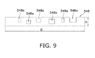
- the second wall 548 of the insulator 54 is formed in a cylindrical shape, but it is assumed that this is developed in a plane shape as shown in FIG. 9 .
- the product of the height h (maximum height) of the second wall 548 and the length B (length of the circumferential direction) of the second wall 548 is referred as total area At.
- the total area of the openings 548a formed in the second wall 548 is Ao.
- the opening ratio of the second wall 548 of the insulator 54 is defined by Ao/At.
- the opening ratio of the second wall 548 of the insulator 54 is 17% or more, the amount of oil outflow to the outside of the scroll compressor 10 is easily reduced. Meanwhile, from the viewpoint of strength of the second wall 548 of the insulator 54, the opening ratio of the second wall 548 of the insulator 54 is preferably less than 40%.
- the crank shaft 80 is a shaft that transmits driving force of the motor 40 to the movable scroll 32.
- the crank shaft 80 is disposed to extend in the up-and-down direction along the axis of the body 21 of the casing 20, and couples the rotor 60 of the motor 40 with the movable scroll 32 of the compression mechanism 30 (see FIG. 1 ).
- the crank shaft 80 includes the main shaft 82 and the eccentric part 81 eccentric with respect to the rotation axis of the main shaft 82 (see FIG. 1 ).
- the eccentric part 81 is disposed at the upper end of the main shaft 82 and is coupled with the boss part 32c of the movable scroll 32.
- the main shaft 82 is rotatably supported by the upper bearing 35 provided in the housing 33, and the lower bearing 90, which will be described later.
- the main shaft 82 is coupled with the rotor 60 of the motor 40 between the upper bearing 35 and the lower bearing 90.
- the main shaft 82 rotates around a center axis extending in the up-and-down direction.
- the oil supply path 84 is formed for supplying the oil L to the compression mechanism 30 and the sliding portion between the crank shaft 80, and the upper bearing 35 and the lower bearing 90.
- the oil in the oil reservoir space 25 passes through the oil supply path 84 and is supplied to the compression mechanism 30 and the like.
- the lower bearing 90 is a bearing pivotally supporting the crank shaft 80 and is disposed below the motor 40 (see FIG. 1 ).
- the lower bearing 90 is fixed to the body 21 of the casing 20.
- the lower bearing 90 rotatably supports the main shaft 82 of the crank shaft 80.
- the volume of the compression chamber Sc of the compression mechanism 30 changes periodically.
- the low-pressure gas refrigerant is supplied to the compression chamber Sc through the intake pipe 23. More specifically, when the volume of the compression chamber Sc on the outermost peripheral side increases, the low-pressure gas refrigerant supplied from the intake pipe 23 is supplied to the compression chamber Sc on the outermost peripheral side. Meanwhile, when the volume of the compression chamber Sc decreases, the gas refrigerant is compressed in the compression chamber Sc and finally becomes a high-pressure gas refrigerant.
- the high-pressure gas refrigerant is discharged from the discharge port 31c located near the center of the upper surface of the fixed scroll 31.
- the high-pressure gas refrigerant discharged from the discharge port 31c passes through the refrigerant passage 31d formed in the fixed scroll 31 and the refrigerant passage 33b formed in the housing 33, flowing into the first space S1 below the housing 33.
- the flow of refrigerant after flowing into the first space S1 is as described above, and thus detailed description thereof will be omitted here.
- the high-pressure gas refrigerant compressed by the compression mechanism 30 is finally discharged from the discharge pipe 24 to the outside of the scroll compressor 10.
- the scroll compressor 10 of the present embodiment includes the compression mechanism 30 as one example of the scroll compression mechanism, the motor 40, and the casing 20.
- the compression mechanism 30 compresses the refrigerant.
- the motor 40 drives the compression mechanism 30.
- the casing 20 houses the compression mechanism 30 and the motor 40.
- the motor 40 includes the stator 50, the rotor 60, the coils 42, and the outgoing lines 70.
- the stator 50 includes the stator core 52 and the insulator 54.
- the rotor 60 is disposed inside the stator 50.
- the coils 42 are wound around the plurality of teeth 524 of the stator core 52 via the insulator 54.
- the outgoing lines 70 are provided at the end of the coils 42.
- the outer radius of the teeth 524 centered on the position of the rotation axis O of the rotor 60 is D1 and the inner radius of the teeth 524 centered on the position of the rotation axis O of the rotor 60 is D2, and that the average distance from the position of the rotation axis O of the rotor 60 to the outgoing lines 70 and/or the film 72 wound around the outgoing lines 70 is da.
- the outgoing lines 70 and/or the film 72 wound around the outgoing lines 70 is disposed to satisfy the relationship of 0.65 ⁇ D 1 ⁇ da / D 1 ⁇ D 2 ⁇ 0.95 .
- the outgoing lines 70 and/or the film 72 wound around the outgoing lines 70 is disposed to satisfy the above-described formula, and the end face of the stator 50 is covered to some extent. As a result, it is possible to inhibit the oil L from moving together with the refrigerant passing through the gap 42a between the coils 42 and being carried out in large quantities to the outside of the scroll compressor 10.
- outgoing lines 70 and the film 72 wound around the outgoing lines 70 are used to cover the end face of the stator 50, the cost can be inhibited more than in the case where the end face of the stator 50 is covered with another member.
- the outgoing lines 70 and/or the film 72 wound around the outgoing lines 70 is disposed to satisfy the relationship of 0.65 ⁇ D 1 ⁇ d / D 1 ⁇ D 2 ⁇ 0.95 .
- d is the distance from the position of the rotation axis O of the rotor 60 to the outgoing lines 70 and/or the film 72 wound around the outgoing lines 70.
- the outgoing lines 70 and/or the film 72 wound around the outgoing lines 70 is disposed to satisfy the above-described formula in the region of 95% or more of the circumferential direction. This makes it particularly easy to inhibit the oil L from moving together with the refrigerant passing through the gap 42a between the coils 42 and being carried out in large quantities to the outside of the scroll compressor 10.
- the gap C between the outgoing lines 70 and the coils 42 in the direction of the rotation axis O of the rotor 60 is 2 mm or more.
- this scroll compressor 10 at least part of the refrigerant that has passed through the gap 42a between the coils 42 can be guided radially outward through the gap C between the outgoing lines 70 and the coils 42. Therefore, this scroll compressor 10 can reduce the total amount of oil L that has moved together with the refrigerant in the gap 42a between the coils 42 from flowing directly into the first space S1 between the motor 40 and the compression mechanism 30 and flowing out of the scroll compressor 10.
- the opening 548a of 17% or more and less than 40% is formed in the second wall 548 of the insulator 54 disposed to surround the outgoing lines 70.
- the second wall 548 is one example of an outer wall of the insulator 54.
- the scroll compressor 10 of the present embodiment includes the guide 26.
- the guide 26 guides the refrigerant discharged by the compression mechanism 30 to the first space S 1 above the motor 40 to the space below the motor 40.
- the film 72 wound around the outgoing lines 70 is disposed at least on the opposite side of the guide 26 across the rotation axis O.
- At least the film 72 is disposed in the region on the opposite side of the guide 26 where the flow velovity of the refrigerant is likely to be particularly large. Therefore, it is possible to inhibit the oil L from moving together with the refrigerant passing through the gap 42a between the coils 42 and being carried out in large quantities to the outside of the scroll compressor 10.
- the opening 548a formed in the second wall 548 of the insulator 54 is illustrated in a rectangular shape, but the shape of the opening 548a is not limited to the rectangular shape, and may be appropriately determined.
- the present disclosure is widely applicable to the scroll compressor and is useful.
- Patent Literature 1 JP 2003-286949 A
Landscapes
- Engineering & Computer Science (AREA)
- Mechanical Engineering (AREA)
- General Engineering & Computer Science (AREA)
- Power Engineering (AREA)
- Applications Or Details Of Rotary Compressors (AREA)
- Rotary Pumps (AREA)
- Compressor (AREA)
Abstract
Description
- The present disclosure relates to a scroll compressor.
- As in Patent Literature 1 (
JP 2003-286949 A - In the scroll compressor as described above, when the refrigerant moves from the space below the motor to the space above the motor, there is a possibility that oil existing in the space below the motor moves to the space above the motor together with the refrigerant and flows out the scroll compressor together with the refrigerant through the discharge pipe.
- Therefore, there is a need for a highly reliable scroll compressor that can reduce such outflow of oil.
- A scroll compressor according to a first aspect includes a scroll compression mechanism, a motor, and a casing. The scroll compression mechanism compresses a refrigerant. The motor drives the scroll compression mechanism. The casing houses the scroll compression mechanism and the motor. The motor includes a stator, a rotor, a coil, and an outgoing line. The stator includes a stator core and an insulator. The rotor is disposed inside the stator. The coil is wound around a plurality of teeth of the stator core via the insulator. The outgoing line is provided at an end of the coil. When the motor is viewed along a rotation axis of the rotor, it is assumed that an outer radius of the teeth centered on a position of the rotation axis of the rotor is D1 and an inner radius of the teeth centered on a position of the rotation axis of the rotor is D2, and that an average distance from the position of the rotation axis of the rotor to the outgoing line and/or a film wound around the outgoing line is da. The outgoing line and/or the film wound around the outgoing line is disposed to satisfy the relationship of 0.65 < (D1 - da)/(D1 - D2) < 0.95.
- In the scroll compressor of the first aspect, the outgoing line and/or the film wound around the outgoing line is disposed to satisfy the above-described formula, and the end face of the stator is covered to some extent. As a result, it is possible to inhibit oil from moving together with the refrigerant passing through a gap between the coils and being carried out in large quantities to the outside of the scroll compressor.
- The scroll compressor according to a second aspect is the scroll compressor according to the first aspect, in which in a region of at least 95% or more of a circumferential direction centered on the position of the rotation axis, the outgoing line and/or the film wound around the outgoing line is disposed to satisfy a relationship of 0.65 < (D1 - d)/(D1 - D2) < 0.95. Here, d is the distance from the position of the rotation axis of the rotor to the outgoing line and/or the film wound around the outgoing line.
- In the scroll compressor of the second aspect, the outgoing line and/or the film wound around the outgoing line is disposed to satisfy the above-described formula in the region of 95% or more of the circumferential direction. This makes it particularly easy to inhibit the oil from moving together with the refrigerant passing through the gap between the coils and being carried out in large quantities to the outside of the scroll compressor.
- The scroll compressor according to a third aspect is the scroll compressor according to the first aspect or the second aspect, in which a gap between the outgoing line and the coil is 2 mm or more in a rotation axis direction of the rotor.
- In the scroll compressor of the third aspect, at least part of the refrigerant that has passed through the gap between the coils can be guided radially outward through the gap between the outgoing line and the coil. Therefore, this scroll compressor can reduce the total amount of oil that has moved together with the refrigerant in the gap between the coils from flowing directly into the space between the motor and the scroll compression mechanism and flowing out of the scroll compressor.
- The scroll compressor according a fourth aspect is the scroll compressor according to any one of the first aspect to the third aspect, in which an opening of 17% or more and less than 40% is formed in an outer wall of the insulator disposed to surround the outgoing line.
- In the scroll compressor of the fourth aspect, at least part of the refrigerant that has passed through the gap between the coils passes through the opening of the outer wall of the insulator and heads for the inner peripheral surface of the casing, colliding with the inner peripheral surface of the casing. Therefore, the outflow of oil to the outside of the scroll compressor is more easily reduced than when the refrigerant that has passed through the gap between the coils heads directly for the outside of the scroll compressor. Since the proportion of the opening to the outer wall of the insulator is less than 40%, the required strength of the outer wall of the insulator can also be maintained.
- The scroll compressor according to a fifth aspect is the scroll compressor according to any one of the first aspect to the fourth aspect, further including a guide. The guide guides the refrigerant discharged by the scroll compression mechanism into the space above the motor to the space below the motor. When the motor is viewed along the rotation axis, the film wound around the outgoing line is disposed at least on the opposite side of the guide across the rotation axis.
- In the scroll compressor of the fifth aspect, the film is disposed at least in the region on the opposite side of the guide where the flow velocity of the refrigerant is likely to become particularly large. Therefore it is possible to inhibit the oil from moving together with the refrigerant passing through the gap between the coils and being carried out in large quantities to the outside of the scroll compressor.
- The scroll compressor according to a sixth aspect is the scroll compressor according to any one of the first aspect to the fifth aspect, in which the motor is a motor of concentrated winding.
-
-
FIG. 1 is a schematic longitudinal cross-sectional view of a scroll compressor according to one embodiment. -
FIG. 2 is a schematic cross-sectional view taken along the line II-II of the scroll compressor ofFIG. 1 . -
FIG. 3 is a schematic plan view of a motor of the scroll compressor ofFIG. 1 . -
FIG. 4 is a schematic plan view schematically showing a disposition state of outgoing lines disposed above an insulator of the motor of the scroll compressor ofFIG. 1 , in which the region where the outgoing lines are disposed is shown by hatching. -
FIG. 5 is a schematic longitudinal cross-sectional view schematically showing an attachment state of the outgoing lines to a stator in the scroll compressor ofFIG. 1 . -
FIG. 6 is a schematic perspective view schematically showing the insulator of the scroll compressor ofFIG. 1 . -
FIG. 7 is experimental data, in the scroll compressor, showing a change in the amount of oil outflow to the outside of the scroll compressor when an average stator end face coverage rate by the outgoing lines is changed. -
FIG. 8 is experimental data, in the scroll compressor, showing the change in the amount of oil outflow to the outside of the scroll compressor when an opening ratio of a second wall of the insulator is changed. -
FIG. 9 is a drawing for describing definition of the opening ratio of the second wall of the insulator. - A
scroll compressor 10 according to one embodiment will be described with reference to the drawings. Note that in order to avoid making the drawings difficult to see, part of reference signs may be omitted in the drawings. - The overall configuration of the
scroll compressor 10 will be described with reference toFIG. 1. FIG. 1 is a schematic longitudinal cross-sectional view of thescroll compressor 10. - The
scroll compressor 10 is used for a refrigeration cycle apparatus such as an air conditioner, and constitutes part of a refrigerant circuit of the refrigeration cycle apparatus. In the refrigeration cycle apparatus, when used for the refrigeration cycle apparatus, thescroll compressor 10 takes in and compresses a low-pressure refrigerant in a refrigeration cycle, and discharges a high-pressure refrigerant in the refrigeration cycle to the refrigerant circuit. - The
scroll compressor 10 mainly includes acasing 20, acompression mechanism 30, amotor 40, acrank shaft 80, and alower bearing 90, as shown inFIG. 1 . - In the
scroll compressor 10, themotor 40 is disposed in a high-pressure space into which a high-pressure refrigerant gas discharged by thecompression mechanism 30 flows. In short, thescroll compressor 10 is a high-pressure dome-type scroll compressor. - The detailed configuration of the
scroll compressor 10 will be described below. - Note that in the following description, for convenience of description, expressions such as "upper" and "lower" may be used for describing directions and placement. Unless otherwise specified, the direction indicated by an arrow U in
FIG. 1 is upward. In the following description, expressions such as parallel, vertical, horizontal, and perpendicular may be used, and include not only the cases of strictly parallel, vertical, horizontal, perpendicular, and the like, but also the cases of substantially parallel, vertical, horizontal, perpendicular, and the like. - The
casing 20 includes abody 21, anupper lid 22a, and alower lid 22b, as shown inFIG. 1 . Thebody 21 is a cylindrical member with upper and lower openings. Theupper lid 22a is provided at the upper end of thebody 21. Thelower lid 22b is provided at the lower end of thebody 21. Thebody 21, theupper lid 22a, and thelower lid 22b are fixed by welding so as to maintain airtightness. - The casing 20 houses components of the
scroll compressor 10 therein, including thecompression mechanism 30, themotor 40, thecrank shaft 80, and thelower bearing 90, as shown inFIG. 1 . - An upper part of the
casing 20 is provided with anintake pipe 23 that penetrates theupper lid 22a of thecasing 20, as shown inFIG. 1 . Theintake pipe 23 is a pipe that supplies a low-pressure gas refrigerant to be compressed by thecompression mechanism 30 from a refrigerant circuit to which thescroll compressor 10 is connected. Theintake pipe 23 is airtightly attached to theupper lid 22a. The lower end of theintake pipe 23 is connected to a fixedscroll 31 of thecompression mechanism 30, which will be described later. Theintake pipe 23 communicates with a compression chamber Sc of thecompression mechanism 30. - A
discharge pipe 24 is provided in an up-and-down middle portion of thebody 21 of thecasing 20 as shown inFIG. 1 . A high-pressure gas refrigerant compressed by thescroll compressor 10 is discharged to thedischarge pipe 24. Thedischarge pipe 24 is airtightly attached to thebody 21. The end of thedischarge pipe 24 within thecasing 20 is disposed in a first space S1 between ahousing 33 of thecompression mechanism 30, which will be described later, and themotor 40. - An
oil reservoir space 25 is formed in the lower part of thecasing 20. Theoil reservoir space 25 stores an oil L (refrigerating machine oil) for lubricating a sliding portion of thecompression mechanism 30 and thecrank shaft 80. The oil L in theoil reservoir space 25 passes through anoil supply path 84 formed inside thecrank shaft 80 and is supplied to the sliding portion of thecompression mechanism 30 and thecrank shaft 80. Part of the oil L that has lubricated thecompression mechanism 30 and thecrank shaft 80 passes through a gap formed between astator 50 of themotor 40, which will be described later, and thebody 21, and returns to theoil reservoir space 25 below thecasing 20. - The
compression mechanism 30 is one example of the scroll compression mechanism that compresses the refrigerant. - The
compression mechanism 30 mainly includes the fixedscroll 31, amovable scroll 32, and thehousing 33, as shown inFIG. 1 . - The fixed
scroll 31 is disposed above thehousing 33, as shown inFIG. 1 . The fixedscroll 31 is disposed in close contact with thehousing 33. Themovable scroll 32 is disposed between the fixedscroll 31 and thehousing 33, as shown inFIG. 1 . Thehousing 33 supports themovable scroll 32 from below. - In the
compression mechanism 30, the fixedscroll 31 and themovable scroll 32 are disposed with a lower surface of anend plate 31a of the fixedscroll 31 and an upper surface of anend plate 32a of themovable scroll 32 facing each other. Thecompression mechanism 30 combines a spiral (involute) fixed-side wrap 31b protruding downward from the lower surface of theend plate 31a of the fixedscroll 31, and a spiral (involute) movable-side wrap 32b protruding upward from the upper surface of theend plate 32a of themovable scroll 32 to form the compression chamber Sc between the adjacent fixed-side wrap 31b and movable-side wrap 32b. - The
movable scroll 32 is provided with aboss part 32c below theend plate 32a. Themovable scroll 32 is coupled with thecrank shaft 80 by inserting aneccentric part 81 of thecrank shaft 80, which will be described later, into theboss part 32c. Thecrank shaft 80 is coupled with arotor 60 of themotor 40, as will be described later. When themotor 40 is driven and thecrank shaft 80 coupled with therotor 60 rotates, themovable scroll 32 revolves with respect to the fixedscroll 31 without rotating by the work of anOldham ring 34 disposed between themovable scroll 32 and thehousing 33. Themovable scroll 32 turns around, thereby compressing the refrigerant in the compression chamber Sc. The refrigerant compressed in the compression chamber Sc is discharged upward from adischarge port 31c formed in theend plate 31a of the fixedscroll 31. The refrigerant discharged from thedischarge port 31c passes through arefrigerant passage 31d formed in the fixedscroll 31 and arefrigerant passage 33b formed in thehousing 33, flowing into the first space S1 below thehousing 33. - The
housing 33 is fixed to thebody 21 of thecasing 20. Although the fixing method is not limited, thehousing 33 is press-fitted into thebody 21 of thecasing 20, and the entire circumference of the outer peripheral surface of thehousing 33 is airtightly fixed to an innerperipheral surface 21a of thebody 21. The fixedscroll 31 is closely fixed to the upper surface of thehousing 33. - A
concave portion 33a recessed downward is formed in the center of the upper portion of thehousing 33. Theboss part 32c of themovable scroll 32 with which theeccentric part 81 of thecrank shaft 80 is coupled is disposed in theconcave portion 33a. Anupper bearing 35 that pivotally supports thecrank shaft 80 is provided below thehousing 33. Theupper bearing 35 rotatably supports amain shaft 82 of thecrank shaft 80, which will be described later. - The
motor 40 will be described with further reference toFIGS. 2 to 6 .FIG. 2 is a schematic cross-sectional view taken along the line II-II of thescroll compressor 10 ofFIG. 1 . InFIG. 2 , parts that are not specifically relevant to the description of themotor 40 is depicted in a simplified manner.FIG. 2 schematically illustratescoils 42 wound aroundteeth 524 of astator core 52, which will be described later.FIG. 3 is a schematic plan view of themotor 40 when themotor 40 is viewed from above.FIG. 4 is a schematic plan view schematically showing a disposition state ofoutgoing lines 70 disposed above aninsulator 54.FIG. 5 is a schematic longitudinal cross-sectional view schematically showing the attachment state of theoutgoing lines 70 to thestator 50.FIG. 6 is a schematic perspective view schematically showing theinsulator 54. To avoid complicated drawing,FIG. 6 depicts theinsulator 54 with illustration of some components omitted. - The
motor 40 is a drive unit that drives thecompression mechanism 30. - The
motor 40 is disposed below thecompression mechanism 30. Specifically, as shown inFIG. 1 , themotor 40 is disposed between theupper bearing 35 provided in thehousing 33 of thecompression mechanism 30 and thelower bearing 90. The first space S1, where the end of thedischarge pipe 24 is disposed, is formed between themotor 40 and thehousing 33. - The
motor 40 mainly includes thestator 50, thecoils 42, therotor 60, and theoutgoing lines 70, as shown inFIG. 1 . Thestator 50 is formed in a cylindrical shape. Therotor 60 is disposed via a small gap (air gap G) in the interior (hollow portion) of thestator 50, as shown inFIG. 1 . - The
stator 50 mainly includes thestator core 52 and theinsulator 54, as shown inFIG. 5 . As shown inFIG. 1 , theinsulator 54 is disposed at both ends of thestator core 52 in the axial direction of the crank shaft 80 (hereinafter, simply referred to as axial direction). - The
stator core 52 is formed by, for example, laminating a plurality of magnetic steel sheets. Thestator core 52 is formed in a substantially cylindrical shape. Thestator core 52 is fixed to the innerperipheral surface 21a of thebody 21 of thecasing 20. Although the fixing method is not limited, thestator core 52 is press-fitted into thebody 21 of thecasing 20. - The
stator core 52 includes anannular yoke 522 and the plurality ofteeth 524, as shown inFIG. 2 . Each of theteeth 524 protrudes radially inward from the inner peripheral surface of theyoke 522. The plurality ofteeth 524 is arranged on theyoke 522 at equal intervals in the circumferential direction. In the present embodiment, thestator core 52 includes 12teeth 524 as shown inFIG. 2 . However, the number of teeth of the scroll compressor of the present disclosure is not limited to 12. - A
core cut 52a cut out so as to be recessed toward the center in the radial direction is formed on part of the outer peripheral surface of the circular shape of theyoke 522. This forms a gap between thecore cut 52a and thebody 21. - The
coils 42 are wound around the plurality ofteeth 524 via theinsulator 54. Each of thecoils 42 is wound around thesingle tooth 524, not across the plurality ofteeth 524. In short, themotor 40 is a motor of concentrated winding. There is a gap 42a between thecoil 42 wound around eachtooth 524 and thecoil 42 wound around thetooth 524 adjacent to the above-describedtooth 524, as shown inFIG. 2 . - The
insulator 54 is attached to the upper and lower ends of thestator core 52 as shown inFIG. 1 . Theinsulator 54 is provided in order to insulate thestator core 52 from thecoil 42. - The
insulator 54 mainly includes anannular part 542, a plurality oftooth parts 544, afirst wall 546, and asecond wall 548, as shown inFIG. 6 . Theannular part 542 is provided at a position corresponding to theyoke 522 of thestator core 52. In other words, theannular part 542 is provided adjacent to theyoke 522 of thestator core 52 in the axial direction. Eachtooth part 544 protrudes radially inward from the inner peripheral surface of theannular part 542. The plurality oftooth parts 544 is arranged on theannular part 542 at equal intervals in the circumferential direction. The plurality oftooth parts 544 is provided at positions corresponding to theteeth 524 of thestator core 52. In other words, the number oftooth parts 544 and the number ofteeth 524 are the same. In the axial direction, each of the plurality oftooth parts 544 is provided adjacent to corresponding one of theteeth 524 of thestator core 52. Thefirst wall 546 is provided at the inner end of eachtooth part 544 and extends on the opposite side of thestator core 52 in the axial direction. Thesecond wall 548 extends on the opposite side of thestator core 52 from the end face of theannular part 542 in the axial direction. Thesecond wall 548 is formed in a substantially cylindrical shape in plan view. - The
second wall 548 of theinsulator 54 disposed above thestator core 52 is provided with a plurality ofopenings 548a. Theopenings 548a here include both through holes and cutouts provided on thesecond wall 548. - Part of the
openings 548a is used for position adjustment of theoutgoing lines 70. For example, in part of theopenings 548a (particularly cutout here), theoutgoing lines 70 are sandwiched and held by thesecond wall 548 adjacent to theopening 548a. For example, when attaching theoutgoing lines 70 to theinsulator 54, part of theopenings 548a (particularly through hole here) is used as a mounting part for afixture 74 of theoutgoing lines 70. - At least part of the
openings 548a is used to guide the refrigerant gas rising from the space below themotor 40 through the gap 42a between thecoils 42 to the innerperipheral surface 21a of thebody 21 of thecasing 20, as will be described later. - The
rotor 60 is rotatably housed in the hollow portion of thestator 50. Acentral hole 62 for inserting themain shaft 82 of thecrank shaft 80 is formed in the central part of the rotor 60 (seeFIG. 1 ). Themain shaft 82 is inserted into thecentral hole 62 of therotor 60 and therotor 60 is fixed to themain shaft 82, whereby therotor 60 is coupled with themovable scroll 32 via thecrank shaft 80. - A plurality of permanent magnets (not shown) is embedded in the
rotor 60. Supply of a current to thecoil 42 of thestator 50 generates a rotating magnetic field. Therotor 60 rotates around a rotation axis O because the permanent magnet provided in therotor 60 is affected by the rotating magnetic field, and causes themovable scroll 32, which is coupled via thecrank shaft 80, to rotate. The rotation axis O of therotor 60 and the rotation axis of thecrank shaft 80 align. - The
motor 40 includes the plurality ofoutgoing lines 70. Eachoutgoing line 70 is provided at an end of eachcoil 42 wound around eachtooth 524 of thestator core 52. Theoutgoing line 70 is a lead wire that connects thecoil 42 to a terminal (not shown) for supplying electric power to thecoil 42. Electric power is supplied to thecoils 42 via theoutgoing lines 70. Theoutgoing lines 70 are disposed above themotor 40 and above thecoils 42 wound around theteeth 524 of thestator core 52 via the insulator 54 (seeFIGS. 1 and3 ). - A
film 72 made of an insulating material may be wound around theoutgoing lines 70 so as to hold the plurality ofoutgoing lines 70 together. Thefilm 72 is made of, for example, resin. Thefilm 72 may be wound around part of theoutgoing lines 70, or may be wound around the entireoutgoing lines 70. - In the present embodiment, the
film 72 wound around theoutgoing lines 70 is disposed in a predetermined region of the circumferential direction in plan view. The position where thefilm 72 is preferably disposed will be described later. Note that thefilm 72 may not be used in themotor 40. - A disposition example in which the
outgoing lines 70 and thefilm 72 wound around theoutgoing lines 70 when themotor 40 is viewed along the rotation axis O of therotor 60 will be described. - To begin with, some words and symbols used in the description will be defined.
- In the following description, when the
motor 40 is viewed along the rotation axis O of therotor 60, an outer radius of theteeth 524 of thestator core 52 centered on the position of the rotation axis O of therotor 60 is represented as symbol D1, and an inner radius of theteeth 524 centered on the position of the rotation axis O is represented as symbol D2. - Note that when the
motor 40 is viewed along the rotation axis O, since theinsulator 54 and theoutgoing lines 70 are actually present above thestator core 52, thestator core 52 cannot be viewed directly. Therefore, when the expression "when themotor 40 is viewed along the rotation axis O" is used here, it is assumed that members that hinder visual observation of an object are removed. - The outer radius D1 of the
teeth 524 when themotor 40 is viewed along the rotation axis O specifically means the distance between the rotation axis O and a connection portion between theyoke 522 and theteeth 524 in plan view (seeFIG. 2 ). The inner radius D2 of theteeth 524 when themotor 40 is viewed along the rotation axis O specifically means the distance between the rotation axis O and an inner peripheral end of the teeth 524 (minimum distance) in plan view (seeFIG. 2 ). - In the following description, the distance from the position of the rotation axis O of the
rotor 60 to theoutgoing lines 70 or thefilm 72 when themotor 40 is viewed along the rotation axis O of therotor 60 is represented as symbol d (seeFIG. 4 ). In short, here, the distance from the rotation axis O to theoutgoing lines 70 and thefilm 72 wound around theoutgoing lines 70 is represented as symbol d in plan view. Note that in themotor 40, the distance (shortest distance) between the rotation axis O and theoutgoing lines 70 or thefilm 72 in plan view does not have to be constant. Note that the distance between the rotation axis O and theoutgoing lines 70 or thefilm 72 being not constant in plan view means that the distance d between the rotation axis O and theoutgoing lines 70 or the film 72 (shortest distance from the position of the rotation axis O to theoutgoing lines 70 or the film 72) differs depending on the position in the circumferential direction. - In the following description, the average distance from the position of the rotation axis O of the
rotor 60 to theoutgoing lines 70 and thefilm 72 wound around theoutgoing lines 70 when themotor 40 is viewed along the rotation axis O of therotor 60 is represented as symbol da (see the two-dot chain line inFIG. 4 ). In other words, here, the average distance from the rotation axis O to theoutgoing lines 70 and thefilm 72 wound around theoutgoing lines 70 in plan view is represented as symbol da. - In the above-described definition of symbols, in the
scroll compressor 10 of the present disclosure, theoutgoing lines 70 and thefilm 72 wound around theoutgoing lines 70 are disposed so as to satisfy the relationship of
scroll compressor 10 of the present disclosure, when themotor 40 is viewed along the rotation axis O of therotor 60, on average, the area surrounded by a circle having the radius da (0.05D1 + 0.95D2 < da < 0.35D1 + 0.65D2) centered on the rotation axis O and a circle having the outer radius D1 centered on the rotation axis O is generally covered with theoutgoing lines 70 or thefilm 72. Note that in order to avoid complicated description, the value of (D1 - da)/(D1 - D2) may be referred to as an average stator end face coverage rate in the following description. - Preferably, in the
scroll compressor 10, in a region of at least 95% or more of the circumferential direction centered on the position of the rotation axis O, theoutgoing lines 70 and thefilm 72 wound around theoutgoing lines 70 are disposed to satisfy the relationship of
scroll compressor 10 of the present disclosure, when themotor 40 is viewed along the rotation axis O of therotor 60, in the region of 95% or more of the circumferential direction, the area surrounded by the circle having the radius d (0.05D1 + 0.95D2 < d < 0.35D1 + 0.65D2) centered on the rotation axis O and the circle having the outer radius D1 centered on the rotation axis O is largely covered with theoutgoing lines 70 or thefilm 72. Note that in order to avoid complicated description, the value of (D1 - d)/(D1 - D2) may be referred to as a stator end face coverage rate in the following description. - More preferably, in the
scroll compressor 10, theoutgoing lines 70 and thefilm 72 are disposed so as to satisfy the relationship of Formula 2 in the entire region of the circumferential direction centered on the position of the rotation axis O. - In short, in the
scroll compressor 10 of the present disclosure, when themotor 40 is viewed along the rotation axis O of therotor 60, most of the region between the outer radius D1 of theteeth 524 of thestator core 52 and the inner radius D2 of theteeth 524 is covered with theoutgoing lines 70 or thefilm 72. - The effect obtained by disposition of the
outgoing lines 70 and thefilm 72satisfying Formula 1 will be described with reference toFIG. 7. FIG. 7 is experimental data, in thescroll compressor 10, showing a change in the amount of oil outflow to the outside of thescroll compressor 10 when the average stator end face coverage rate [%] by theoutgoing lines 70 is changed. Structure of thescroll compressor 10 used in the experiment and an operating condition of thescroll compressor 10 are the same except for the average stator end face coverage rate. - Before describing the effect, the flow of refrigerant around the
motor 40 during the operation of thescroll compressor 10 will be described. - As described above, the refrigerant compressed by the
compression mechanism 30 passes through therefrigerant passage 31d formed in the fixedscroll 31 and therefrigerant passage 33b formed in thehousing 33, and then flows into the first space S1. - As shown in
FIG. 1 , aguide 26 is provided in the first space S1 to guide part of the refrigerant that has passed through therefrigerant passage 31d and therefrigerant passage 33b and has flowed into the first space S1 to the gap between thecore cut 52a of thestator core 52 and the innerperipheral surface 21a of thebody 21 of thecasing 20. Specifically, part of the refrigerant discharged by thecompression mechanism 30 into the first space S1 is guided by theguide 26 to flow downward, and flows downward through a gap between part of the core cut 52a of thestator core 52 and the innerperipheral surface 21a of the body 21 (referred to as first gap) to the space below themotor 40. Note that theguide 26 also has a function of dividing part of the refrigerant flowing downward through theguide 26 to generate the flow of refrigerant in the circumferential direction in the first space S1. - The refrigerant guided by the
guide 26 and flowing into the space below themotor 40 changes the flow direction upward. Part of the refrigerant that has flowed into the space below themotor 40 flows upward through the air gap G between thestator 50 and therotor 60 and a gap between thecore cut 52a and the innerperipheral surface 21a of the body 21 (gap other than the first gap through which the refrigerant flows downward) (seeFIG. 1 ). Part of the refrigerant that has flowed into the space below themotor 40 flows upward through the gap 42a formed between thecoils 42. - The refrigerant guided by the
guide 26 in the circumferential direction in the first space S1, and the refrigerant that has flowed into the first space S1 from the space below themotor 40 through the air gap G, the gap between thecore cut 52a and the innerperipheral surface 21a of thebody 21, the gap 42a between thecoils 42, and the like are discharged from thedischarge pipe 24 to the outside of thecasing 20. - The inventor of the present application has found that, since such a flow of refrigerant occurs around the
motor 40, when an upper portion of thecoils 42 of themotor 40 is not well covered with the outgoing lines 70 (in other words, when the average stator end face coverage rate is low), the oil L existing below themotor 40 easily moves to the first space S1 together with the refrigerant flowing upward through the gap 42a formed between thecoils 42, and the amount of oil L that flows out of thescroll compressor 10 together with the refrigerant tends to increase (seeFIG. 7 ). The inventor of the present application has found that the amount of oil L flowing out of thescroll compressor 10 is reduced by making the average stator end face coverage rate larger than 0.65 in the motor 40 (seeFIG. 7 ). Furthermore, the inventor of the present application has found that if the average stator end face coverage rate is too large (larger than 0.95) in themotor 40, the amount of oil L flowing out of thescroll compressor 10 tends to increase (seeFIG. 7 ). - Considering these results, in the
scroll compressor 10 of the present embodiment, theoutgoing lines 70 and/or thefilm 72 wound around theoutgoing lines 70 are disposed so as to satisfyFormula 1. Such a configuration allows thescroll compressor 10 of the present embodiment to reduce the amount of oil L flowing out of thescroll compressor 10. - Note that even when the average stator end face coverage rate satisfies
Formula 1, if the area where the stator end face coverage rate is not in the range from 0.65 to 0.95 increases, the effect of inhibiting the amount of oil outflow to the outside of thescroll compressor 10 by theoutgoing lines 70 or thefilm 72 tends to decrease at these areas. Therefore, the stator end face coverage rate preferably satisfies the relationship of Formula 2 in most regions. - In particular, as described above, the
scroll compressor 10 preferably satisfies the relationship of Formula 2 in the region of 95% or more of the circumferential direction when themotor 40 is viewed along the rotation axis O of therotor 60. More preferably, thescroll compressor 10 preferably satisfies the relationship of Formula 2 in the entire region when themotor 40 is viewed along the rotation axis O of therotor 60, as described above. - Such a configuration allows the
scroll compressor 10 of the present embodiment to reduce the amount of oil L flowing out of thescroll compressor 10 particularly easily. - As described above, the refrigerant guided by the
guide 26 and flowing into the space below themotor 40 changes the flow direction of the refrigerant upward in the space below themotor 40. The upward flow velocity of the refrigerant is likely to be particularly large on the opposite side of theguide 26 across the rotation axis O when themotor 40 is viewed along the rotation axis O of the rotor 60 (rotation axis of crank shaft 80). Therefore, thefilm 72 wound around theoutgoing lines 70 is preferably disposed at a position where the upward flow velocity of the refrigerant is likely to increase, as shown inFIG. 3 , in order to inhibit the refrigerant that has passed through the gap 42a from flowing directly into the first space S1 (without hitting other members). The reason why it is preferable to dispose thefilm 72 is that, if theoutgoing lines 70 around which nofilm 72 is wound are disposed, the refrigerant may pass through a small gap formed between theoutgoing line 70 and theoutgoing line 70. - Preferably, in the
scroll compressor 10, theoutgoing lines 70 and thefilm 72 wound around theoutgoing lines 70 are disposed such that the gap C in the direction of the rotation axis O between theoutgoing lines 70 and thefilm 72, and the coils 42 (seeFIG. 5 ) is 2 mm or more. Specifically, when theoutgoing lines 70 are attached to thesecond wall 548 of theinsulator 54 or the like, theoutgoing lines 70 are preferably fixed to theinsulator 54 with thefixture 74 such that the gap C of 2 mm or more is formed between theoutgoing lines 70 and thefilm 72, and thecoils 42. Thefixture 74 is, for example, a tie strap. - Since the gap C of 2 mm or more is provided from the
outgoing lines 70 and thefilm 72 to thecoils 42, the refrigerant that has risen through the gap 42a between thecoils 42 to the upper end position of thecoils 42 can be guided radially outward through the gap C. The refrigerant guided radially outward between thecoils 42, and theoutgoing lines 70 or thefilm 72 wound around theoutgoing lines 70 passes through theopening 548a formed in thesecond wall 548 of theinsulator 54 and collides with the innerperipheral surface 21a of thebody 21 of thecasing 20. By causing the refrigerant to collide with the innerperipheral surface 21a of thebody 21 in this way, the oil L carried with the refrigerant can be stuck as oil droplets to the innerperipheral surface 21a of thebody 21 and the amount of oil outflow to the outside of thescroll compressor 10 can be reduced. - Note that in general, the
opening 548a is conventionally formed in thesecond wall 548 of theinsulator 54 for the purpose of fixing theoutgoing lines 70, or the like. However, the inventor of the present application has found that, by increasing the area of theopening 548a formed in thesecond wall 548 of theinsulator 54 and increasing the amount of refrigerant that collides with the innerperipheral surface 21a of thebody 21 of thecasing 20, the amount of oil outflow to the outside of thescroll compressor 10 tends to reduce. This will be described with reference toFIG. 8. FIG. 8 is experimental data, in thescroll compressor 10, showing the change in the amount of oil outflow to the outside of thescroll compressor 10 when the average stator end face coverage rate is fixed at 0.65 and an opening ratio of thesecond wall 548 of theinsulator 54 is changed. - To provide a description here, the opening ratio of the
second wall 548 of theinsulator 54 is defined. Thesecond wall 548 of theinsulator 54 is formed in a cylindrical shape, but it is assumed that this is developed in a plane shape as shown inFIG. 9 . At this time, the product of the height h (maximum height) of thesecond wall 548 and the length B (length of the circumferential direction) of thesecond wall 548 is referred as total area At. It is assumed that the total area of theopenings 548a formed in thesecond wall 548 is Ao. At this time, the opening ratio of thesecond wall 548 of theinsulator 54 is defined by Ao/At. - As a result of experiment, as shown in
FIG. 8 , it has been found that, when the opening ratio of thesecond wall 548 of theinsulator 54 is 17% or more, the amount of oil outflow to the outside of thescroll compressor 10 is easily reduced. Meanwhile, from the viewpoint of strength of thesecond wall 548 of theinsulator 54, the opening ratio of thesecond wall 548 of theinsulator 54 is preferably less than 40%. - The
crank shaft 80 is a shaft that transmits driving force of themotor 40 to themovable scroll 32. Thecrank shaft 80 is disposed to extend in the up-and-down direction along the axis of thebody 21 of thecasing 20, and couples therotor 60 of themotor 40 with themovable scroll 32 of the compression mechanism 30 (seeFIG. 1 ). - The
crank shaft 80 includes themain shaft 82 and theeccentric part 81 eccentric with respect to the rotation axis of the main shaft 82 (seeFIG. 1 ). - The
eccentric part 81 is disposed at the upper end of themain shaft 82 and is coupled with theboss part 32c of themovable scroll 32. - The
main shaft 82 is rotatably supported by theupper bearing 35 provided in thehousing 33, and thelower bearing 90, which will be described later. Themain shaft 82 is coupled with therotor 60 of themotor 40 between theupper bearing 35 and thelower bearing 90. Themain shaft 82 rotates around a center axis extending in the up-and-down direction. - Inside the
crank shaft 80, theoil supply path 84 is formed for supplying the oil L to thecompression mechanism 30 and the sliding portion between thecrank shaft 80, and theupper bearing 35 and thelower bearing 90. The oil in theoil reservoir space 25 passes through theoil supply path 84 and is supplied to thecompression mechanism 30 and the like. - The
lower bearing 90 is a bearing pivotally supporting thecrank shaft 80 and is disposed below the motor 40 (seeFIG. 1 ). Thelower bearing 90 is fixed to thebody 21 of thecasing 20. Thelower bearing 90 rotatably supports themain shaft 82 of thecrank shaft 80. - The operation of the
scroll compressor 10 will be described. - When a current is supplied to the
coils 42 via theoutgoing lines 70 and themotor 40 is driven, therotor 60 rotates and thecrank shaft 80 coupled with therotor 60 rotates. The rotation of thecrank shaft 80 drives themovable scroll 32. Themovable scroll 32 revolves with respect to the fixedscroll 31 without rotating. - With the revolution of the
movable scroll 32, the volume of the compression chamber Sc of thecompression mechanism 30 changes periodically. When the volume of the compression chamber Sc increases, the low-pressure gas refrigerant is supplied to the compression chamber Sc through theintake pipe 23. More specifically, when the volume of the compression chamber Sc on the outermost peripheral side increases, the low-pressure gas refrigerant supplied from theintake pipe 23 is supplied to the compression chamber Sc on the outermost peripheral side. Meanwhile, when the volume of the compression chamber Sc decreases, the gas refrigerant is compressed in the compression chamber Sc and finally becomes a high-pressure gas refrigerant. The high-pressure gas refrigerant is discharged from thedischarge port 31c located near the center of the upper surface of the fixedscroll 31. The high-pressure gas refrigerant discharged from thedischarge port 31c passes through therefrigerant passage 31d formed in the fixedscroll 31 and therefrigerant passage 33b formed in thehousing 33, flowing into the first space S1 below thehousing 33. The flow of refrigerant after flowing into the first space S1 is as described above, and thus detailed description thereof will be omitted here. The high-pressure gas refrigerant compressed by thecompression mechanism 30 is finally discharged from thedischarge pipe 24 to the outside of thescroll compressor 10. - (4-1)
Thescroll compressor 10 of the present embodiment includes thecompression mechanism 30 as one example of the scroll compression mechanism, themotor 40, and thecasing 20. Thecompression mechanism 30 compresses the refrigerant. Themotor 40 drives thecompression mechanism 30. The casing 20 houses thecompression mechanism 30 and themotor 40. Themotor 40 includes thestator 50, therotor 60, thecoils 42, and theoutgoing lines 70. Thestator 50 includes thestator core 52 and theinsulator 54. Therotor 60 is disposed inside thestator 50. Thecoils 42 are wound around the plurality ofteeth 524 of thestator core 52 via theinsulator 54. Theoutgoing lines 70 are provided at the end of thecoils 42. When themotor 40 is viewed along the rotation axis of therotor 60, it is assumed that the outer radius of theteeth 524 centered on the position of the rotation axis O of therotor 60 is D1 and the inner radius of theteeth 524 centered on the position of the rotation axis O of therotor 60 is D2, and that the average distance from the position of the rotation axis O of therotor 60 to theoutgoing lines 70 and/or thefilm 72 wound around theoutgoing lines 70 is da. Theoutgoing lines 70 and/or thefilm 72 wound around theoutgoing lines 70 is disposed to satisfy the relationship of
- In this
scroll compressor 10, theoutgoing lines 70 and/or thefilm 72 wound around theoutgoing lines 70 is disposed to satisfy the above-described formula, and the end face of thestator 50 is covered to some extent. As a result, it is possible to inhibit the oil L from moving together with the refrigerant passing through the gap 42a between thecoils 42 and being carried out in large quantities to the outside of thescroll compressor 10. - Here, since the
outgoing lines 70 and thefilm 72 wound around theoutgoing lines 70 are used to cover the end face of thestator 50, the cost can be inhibited more than in the case where the end face of thestator 50 is covered with another member. - (4-2)
In thescroll compressor 10 of the present embodiment, in the region of at least 95% or more of the circumferential direction centered on the position of the rotation axis O, theoutgoing lines 70 and/or thefilm 72 wound around theoutgoing lines 70 is disposed to satisfy the relationship of
rotor 60 to theoutgoing lines 70 and/or thefilm 72 wound around theoutgoing lines 70. - In this
scroll compressor 10, theoutgoing lines 70 and/or thefilm 72 wound around theoutgoing lines 70 is disposed to satisfy the above-described formula in the region of 95% or more of the circumferential direction. This makes it particularly easy to inhibit the oil L from moving together with the refrigerant passing through the gap 42a between thecoils 42 and being carried out in large quantities to the outside of thescroll compressor 10. - (4-3)
In thescroll compressor 10 of the present embodiment, the gap C between theoutgoing lines 70 and thecoils 42 in the direction of the rotation axis O of therotor 60 is 2 mm or more. - In this
scroll compressor 10, at least part of the refrigerant that has passed through the gap 42a between thecoils 42 can be guided radially outward through the gap C between theoutgoing lines 70 and thecoils 42. Therefore, thisscroll compressor 10 can reduce the total amount of oil L that has moved together with the refrigerant in the gap 42a between thecoils 42 from flowing directly into the first space S1 between themotor 40 and thecompression mechanism 30 and flowing out of thescroll compressor 10. - (4-4)
In thescroll compressor 10 of the present embodiment, theopening 548a of 17% or more and less than 40% is formed in thesecond wall 548 of theinsulator 54 disposed to surround theoutgoing lines 70. Thesecond wall 548 is one example of an outer wall of theinsulator 54. - In this
scroll compressor 10, at least part of the refrigerant that has passed through the gap 42a between thecoils 42 passes through theopening 548a of thesecond wall 548 of theinsulator 54 and heads for the innerperipheral surface 21a of thebody 21 of thecasing 20, colliding with the innerperipheral surface 21a. Therefore, the outflow of oil L to the outside of thescroll compressor 10 is more easily reduced than when the refrigerant that has passed through the gap 42a between thecoils 42 heads directly for the outside of thescroll compressor 10. Since the proportion of theopening 548a to thesecond wall 548 of theinsulator 54 is less than 40%, the required strength of thesecond wall 548 of theinsulator 54 can also be maintained. - (4-5)
Thescroll compressor 10 of the present embodiment includes theguide 26. Theguide 26 guides the refrigerant discharged by thecompression mechanism 30 to thefirst space S 1 above themotor 40 to the space below themotor 40. When themotor 40 is viewed along the rotation axis O, thefilm 72 wound around theoutgoing lines 70 is disposed at least on the opposite side of theguide 26 across the rotation axis O. - In this
scroll compressor 10, at least thefilm 72 is disposed in the region on the opposite side of theguide 26 where the flow velovity of the refrigerant is likely to be particularly large. Therefore, it is possible to inhibit the oil L from moving together with the refrigerant passing through the gap 42a between thecoils 42 and being carried out in large quantities to the outside of thescroll compressor 10. - Modifications of the above-described embodiment will be described below. Note that a plurality of modifications described below may be appropriately combined as long as no contradiction with each other arises.
- The above-described embodiment has described the case where the
film 72 is wound around part of theoutgoing lines 70, but thefilm 72 may not be wound around theoutgoing lines 70, or thefilm 72 may be wound around the entireoutgoing lines 70. - In the above-described embodiment, the
opening 548a formed in thesecond wall 548 of theinsulator 54 is illustrated in a rectangular shape, but the shape of theopening 548a is not limited to the rectangular shape, and may be appropriately determined. - The embodiment of the present disclosure has been described above. It will be understood that various changes to modes and details can be made without departing from the spirit and scope of the present disclosure recited in the claims.
- The present disclosure is widely applicable to the scroll compressor and is useful.
-
- 10: scroll compressor
- 20: casing
- 30: compression mechanism (scroll compression mechanism)
- 40: motor
- 42: coil
- 50: stator
- 52: stator core
- 54: insulator
- 60: rotor
- 70: outgoing line
- 72: film
- 524: teeth
- 548: second wall (outer wall)
- 548a: opening
- C: gap
- O: rotation axis (rotation axis of rotor)
- S1: first space (space)
- Patent Literature 1:
JP 2003-286949 A
Claims (6)
- A scroll compressor (10) comprising:a scroll compression mechanism (30) configured to compress a refrigerant;a motor (40) configured to drive the scroll compression mechanism; anda casing (20) housing the scroll compression mechanism and the motor,the motor including:a stator (50) including a stator core (52) and an insulator (54);a rotor (60) disposed inside the stator;a coil (42) wound around a plurality of teeth (524) of the stator core via the insulator; andan outgoing line (70) provided at an end of the coil,when the motor is viewed along a rotation axis (O) of the rotor,the outgoing line and/or a film (72) wound around the outgoing line satisfies a relationship of:
 where an outer radius of the teeth centered on a position of the rotation axis of the rotor is D1, and an inner radius of the teeth is D2, andan average distance from the position of the rotation axis of the rotor to the outgoing line and/or the film (72) wound around the outgoing line is da.
 - The scroll compressor according to claim 1, wherein
in a region of at least 95% or more of a circumferential direction centered on the position of the rotation axis, the outgoing line and/or the film wound around the outgoing line is disposed to satisfy a relationship of
- The scroll compressor according to claim 1 or 2, wherein a gap (C) between the outgoing line and/or the film wound around the outgoing line, and the coil is 2 mm or more in a rotation axis direction of the rotor.
- The scroll compressor according to any one of claims 1 to 3, wherein an opening (548a) of 17% or more and less than 40% is formed in an outer wall (548) of the insulator disposed to surround the outgoing line.
- The scroll compressor according to any one of claims 1 to 4, further comprising a guide configured to guide the refrigerant discharged by the scroll compression mechanism into space (S1) above the motor to space below the motor,
wherein when the motor is viewed along the rotation axis, the film wound around the outgoing line is disposed at least on an opposite side of the guide across the rotation axis. - The scroll compressor according to any one of claims 1 to 5, wherein the motor is a motor of concentrated winding.
Applications Claiming Priority (2)
| Application Number | Priority Date | Filing Date | Title |
|---|---|---|---|
| JP2019217312A JP6844676B1 (en) | 2019-11-29 | 2019-11-29 | Scroll compressor |
| PCT/JP2020/043641 WO2021106861A1 (en) | 2019-11-29 | 2020-11-24 | Scroll compressor |
Publications (3)
| Publication Number | Publication Date |
|---|---|
| EP4067660A1 true EP4067660A1 (en) | 2022-10-05 |
| EP4067660A4 EP4067660A4 (en) | 2023-01-18 |
| EP4067660B1 EP4067660B1 (en) | 2024-01-17 |
Family
ID=74860739
Family Applications (1)
| Application Number | Title | Priority Date | Filing Date |
|---|---|---|---|
| EP20893617.9A Active EP4067660B1 (en) | 2019-11-29 | 2020-11-24 | Scroll compressor |
Country Status (6)
| Country | Link |
|---|---|
| US (1) | US11703054B2 (en) |
| EP (1) | EP4067660B1 (en) |
| JP (1) | JP6844676B1 (en) |
| CN (1) | CN114729643B (en) |
| ES (1) | ES2975219T3 (en) |
| WO (1) | WO2021106861A1 (en) |
Families Citing this family (1)
| Publication number | Priority date | Publication date | Assignee | Title |
|---|---|---|---|---|
| JP7534659B2 (en) | 2022-07-11 | 2024-08-15 | ダイキン工業株式会社 | Scroll compressor and refrigerant cycle device |
Family Cites Families (19)
| Publication number | Priority date | Publication date | Assignee | Title |
|---|---|---|---|---|
| TW564285B (en) * | 1999-06-29 | 2003-12-01 | Sanyo Electric Co | Sealed rotary compressor |
| JP4592143B2 (en) * | 2000-04-06 | 2010-12-01 | パナソニック株式会社 | Compressor and electric motor |
| JP2002044892A (en) * | 2000-07-27 | 2002-02-08 | Matsushita Electric Ind Co Ltd | Electric motor and electric compressor equipped with it |
| JP3832369B2 (en) * | 2002-03-28 | 2006-10-11 | ダイキン工業株式会社 | High and low pressure dome type compressor |
| JP4433184B2 (en) * | 2004-11-05 | 2010-03-17 | 株式会社富士通ゼネラル | Compressor |
| JP2008019800A (en) * | 2006-07-13 | 2008-01-31 | Sanden Corp | Electric wire holding structure for electric compressor, and method of holding electric wire for electric compressor |
| JP4614004B2 (en) * | 2009-02-03 | 2011-01-19 | ダイキン工業株式会社 | Stator, motor and compressor |
| JP2010213527A (en) * | 2009-03-12 | 2010-09-24 | Daikin Ind Ltd | Stator, motor, and compressor |
| JP5482121B2 (en) * | 2009-11-10 | 2014-04-23 | 株式会社富士通ゼネラル | Rotating electric machine stator |
| JP5772296B2 (en) * | 2011-06-28 | 2015-09-02 | 株式会社豊田自動織機 | Electric compressor |
| JP5858009B2 (en) * | 2013-07-23 | 2016-02-10 | 株式会社豊田自動織機 | Method for producing interphase insulating sheet in rotating electrical machine and electric compressor |
| JP5831533B2 (en) * | 2013-12-02 | 2015-12-09 | ダイキン工業株式会社 | Compressor |
| JP6596222B2 (en) * | 2015-04-14 | 2019-10-23 | 日立ジョンソンコントロールズ空調株式会社 | Hermetic electric compressor |
| JP5988005B1 (en) * | 2015-04-16 | 2016-09-07 | ダイキン工業株式会社 | Stator and motor and compressor having the same |
| JP6115672B2 (en) * | 2015-04-16 | 2017-04-19 | ダイキン工業株式会社 | Stator and motor and compressor having the same |
| JP6664958B2 (en) * | 2015-12-25 | 2020-03-13 | サンデンホールディングス株式会社 | Compressor motor and compressor provided with the same |
| JP6428739B2 (en) * | 2016-09-30 | 2018-11-28 | 株式会社富士通ゼネラル | Compressor |
| JP6399075B2 (en) * | 2016-11-30 | 2018-10-03 | 株式会社富士通ゼネラル | Compressor |
| DE102019107509A1 (en) * | 2018-04-26 | 2019-10-31 | Hanon Systems | Device for driving a compressor |
-
2019
- 2019-11-29 JP JP2019217312A patent/JP6844676B1/en active Active
-
2020
- 2020-11-24 WO PCT/JP2020/043641 patent/WO2021106861A1/en not_active Ceased
- 2020-11-24 ES ES20893617T patent/ES2975219T3/en active Active
- 2020-11-24 EP EP20893617.9A patent/EP4067660B1/en active Active
- 2020-11-24 CN CN202080082261.6A patent/CN114729643B/en active Active
-
2022
- 2022-05-24 US US17/752,468 patent/US11703054B2/en active Active
Also Published As
| Publication number | Publication date |
|---|---|
| EP4067660A4 (en) | 2023-01-18 |
| JP2021085404A (en) | 2021-06-03 |
| EP4067660B1 (en) | 2024-01-17 |
| CN114729643A (en) | 2022-07-08 |
| JP6844676B1 (en) | 2021-03-17 |
| US11703054B2 (en) | 2023-07-18 |
| WO2021106861A1 (en) | 2021-06-03 |
| ES2975219T3 (en) | 2024-07-04 |
| US20220282730A1 (en) | 2022-09-08 |
| CN114729643B (en) | 2023-04-21 |
Similar Documents
| Publication | Publication Date | Title |
|---|---|---|
| EP2107667B1 (en) | Motor and compressor | |
| EP2873858B1 (en) | Electric compressor | |
| US8513851B2 (en) | Insulator for motor, stator, motor and compressor | |
| US9234527B2 (en) | Motor driven compressor | |
| EP2631483A1 (en) | Hermetically sealed electric motor compressor | |
| EP4067660B1 (en) | Scroll compressor | |
| US20160315517A1 (en) | Compressor | |
| EP4365449B1 (en) | Electric compressor | |
| EP1640609A1 (en) | Compressor | |
| EP3193429B1 (en) | Motor and electric compressor | |
| KR101038634B1 (en) | compressor | |
| US20170317549A1 (en) | Stator and motor | |
| JP3992071B1 (en) | Compressor | |
| CN220354041U (en) | Scroll compressor and refrigerant cycle device | |
| JP7648931B2 (en) | Compressors and refrigeration equipment | |
| JP2005264749A (en) | Electric compressor | |
| EP3258106A1 (en) | Hermetically sealed electric compressor | |
| JP2012202214A (en) | Compressor | |
| CN120322620A (en) | Electric compressor | |
| JP2022157801A (en) | compressor | |
| JP2008121487A (en) | Compressor |
Legal Events
| Date | Code | Title | Description |
|---|---|---|---|
| STAA | Information on the status of an ep patent application or granted ep patent |
Free format text: STATUS: THE INTERNATIONAL PUBLICATION HAS BEEN MADE |
|
| PUAI | Public reference made under article 153(3) epc to a published international application that has entered the european phase |
Free format text: ORIGINAL CODE: 0009012 |
|
| STAA | Information on the status of an ep patent application or granted ep patent |
Free format text: STATUS: REQUEST FOR EXAMINATION WAS MADE |
|
| 17P | Request for examination filed |
Effective date: 20220614 |
|
| AK | Designated contracting states |
Kind code of ref document: A1 Designated state(s): AL AT BE BG CH CY CZ DE DK EE ES FI FR GB GR HR HU IE IS IT LI LT LU LV MC MK MT NL NO PL PT RO RS SE SI SK SM TR |
|
| A4 | Supplementary search report drawn up and despatched |
Effective date: 20221215 |
|
| RAP3 | Party data changed (applicant data changed or rights of an application transferred) |
Owner name: DAIKIN INDUSTRIES, LTD. |
|
| RIC1 | Information provided on ipc code assigned before grant |
Ipc: F04C 18/02 20060101ALI20221209BHEP Ipc: F04C 29/02 20060101AFI20221209BHEP |
|
| DAV | Request for validation of the european patent (deleted) | ||
| DAX | Request for extension of the european patent (deleted) | ||
| P01 | Opt-out of the competence of the unified patent court (upc) registered |
Effective date: 20230525 |
|
| GRAP | Despatch of communication of intention to grant a patent |
Free format text: ORIGINAL CODE: EPIDOSNIGR1 |
|
| STAA | Information on the status of an ep patent application or granted ep patent |
Free format text: STATUS: GRANT OF PATENT IS INTENDED |
|
| INTG | Intention to grant announced |
Effective date: 20231013 |
|
| GRAS | Grant fee paid |
Free format text: ORIGINAL CODE: EPIDOSNIGR3 |
|
| GRAA | (expected) grant |
Free format text: ORIGINAL CODE: 0009210 |
|
| STAA | Information on the status of an ep patent application or granted ep patent |
Free format text: STATUS: THE PATENT HAS BEEN GRANTED |
|
| AK | Designated contracting states |
Kind code of ref document: B1 Designated state(s): AL AT BE BG CH CY CZ DE DK EE ES FI FR GB GR HR HU IE IS IT LI LT LU LV MC MK MT NL NO PL PT RO RS SE SI SK SM TR |
|
| REG | Reference to a national code |
Ref country code: GB Ref legal event code: FG4D |
|
| REG | Reference to a national code |
Ref country code: DE Ref legal event code: R096 Ref document number: 602020024650 Country of ref document: DE |
|
| REG | Reference to a national code |
Ref country code: CH Ref legal event code: EP |
|
| REG | Reference to a national code |
Ref country code: IE Ref legal event code: FG4D |
|
| REG | Reference to a national code |
Ref country code: LT Ref legal event code: MG9D |
|
| REG | Reference to a national code |
Ref country code: NL Ref legal event code: MP Effective date: 20240117 |
|
| REG | Reference to a national code |
Ref country code: AT Ref legal event code: MK05 Ref document number: 1650695 Country of ref document: AT Kind code of ref document: T Effective date: 20240117 |
|
| PG25 | Lapsed in a contracting state [announced via postgrant information from national office to epo] |
Ref country code: NL Free format text: LAPSE BECAUSE OF FAILURE TO SUBMIT A TRANSLATION OF THE DESCRIPTION OR TO PAY THE FEE WITHIN THE PRESCRIBED TIME-LIMIT Effective date: 20240117 |
|
| PG25 | Lapsed in a contracting state [announced via postgrant information from national office to epo] |
Ref country code: NL Free format text: LAPSE BECAUSE OF FAILURE TO SUBMIT A TRANSLATION OF THE DESCRIPTION OR TO PAY THE FEE WITHIN THE PRESCRIBED TIME-LIMIT Effective date: 20240117 |
|
| PG25 | Lapsed in a contracting state [announced via postgrant information from national office to epo] |
Ref country code: IS Free format text: LAPSE BECAUSE OF FAILURE TO SUBMIT A TRANSLATION OF THE DESCRIPTION OR TO PAY THE FEE WITHIN THE PRESCRIBED TIME-LIMIT Effective date: 20240517 |
|
| REG | Reference to a national code |
Ref country code: ES Ref legal event code: FG2A Ref document number: 2975219 Country of ref document: ES Kind code of ref document: T3 Effective date: 20240704 |
|
| PG25 | Lapsed in a contracting state [announced via postgrant information from national office to epo] |
Ref country code: LT Free format text: LAPSE BECAUSE OF FAILURE TO SUBMIT A TRANSLATION OF THE DESCRIPTION OR TO PAY THE FEE WITHIN THE PRESCRIBED TIME-LIMIT Effective date: 20240117 |
|
| PG25 | Lapsed in a contracting state [announced via postgrant information from national office to epo] |
Ref country code: GR Free format text: LAPSE BECAUSE OF FAILURE TO SUBMIT A TRANSLATION OF THE DESCRIPTION OR TO PAY THE FEE WITHIN THE PRESCRIBED TIME-LIMIT Effective date: 20240418 |
|
| PG25 | Lapsed in a contracting state [announced via postgrant information from national office to epo] |
Ref country code: HR Free format text: LAPSE BECAUSE OF FAILURE TO SUBMIT A TRANSLATION OF THE DESCRIPTION OR TO PAY THE FEE WITHIN THE PRESCRIBED TIME-LIMIT Effective date: 20240117 Ref country code: RS Free format text: LAPSE BECAUSE OF FAILURE TO SUBMIT A TRANSLATION OF THE DESCRIPTION OR TO PAY THE FEE WITHIN THE PRESCRIBED TIME-LIMIT Effective date: 20240417 |
|
| PG25 | Lapsed in a contracting state [announced via postgrant information from national office to epo] |
Ref country code: AT Free format text: LAPSE BECAUSE OF FAILURE TO SUBMIT A TRANSLATION OF THE DESCRIPTION OR TO PAY THE FEE WITHIN THE PRESCRIBED TIME-LIMIT Effective date: 20240117 |
|
| PG25 | Lapsed in a contracting state [announced via postgrant information from national office to epo] |
Ref country code: RS Free format text: LAPSE BECAUSE OF FAILURE TO SUBMIT A TRANSLATION OF THE DESCRIPTION OR TO PAY THE FEE WITHIN THE PRESCRIBED TIME-LIMIT Effective date: 20240417 Ref country code: NO Free format text: LAPSE BECAUSE OF FAILURE TO SUBMIT A TRANSLATION OF THE DESCRIPTION OR TO PAY THE FEE WITHIN THE PRESCRIBED TIME-LIMIT Effective date: 20240417 Ref country code: LT Free format text: LAPSE BECAUSE OF FAILURE TO SUBMIT A TRANSLATION OF THE DESCRIPTION OR TO PAY THE FEE WITHIN THE PRESCRIBED TIME-LIMIT Effective date: 20240117 Ref country code: IS Free format text: LAPSE BECAUSE OF FAILURE TO SUBMIT A TRANSLATION OF THE DESCRIPTION OR TO PAY THE FEE WITHIN THE PRESCRIBED TIME-LIMIT Effective date: 20240517 Ref country code: HR Free format text: LAPSE BECAUSE OF FAILURE TO SUBMIT A TRANSLATION OF THE DESCRIPTION OR TO PAY THE FEE WITHIN THE PRESCRIBED TIME-LIMIT Effective date: 20240117 Ref country code: GR Free format text: LAPSE BECAUSE OF FAILURE TO SUBMIT A TRANSLATION OF THE DESCRIPTION OR TO PAY THE FEE WITHIN THE PRESCRIBED TIME-LIMIT Effective date: 20240418 Ref country code: FI Free format text: LAPSE BECAUSE OF FAILURE TO SUBMIT A TRANSLATION OF THE DESCRIPTION OR TO PAY THE FEE WITHIN THE PRESCRIBED TIME-LIMIT Effective date: 20240117 Ref country code: BG Free format text: LAPSE BECAUSE OF FAILURE TO SUBMIT A TRANSLATION OF THE DESCRIPTION OR TO PAY THE FEE WITHIN THE PRESCRIBED TIME-LIMIT Effective date: 20240117 Ref country code: AT Free format text: LAPSE BECAUSE OF FAILURE TO SUBMIT A TRANSLATION OF THE DESCRIPTION OR TO PAY THE FEE WITHIN THE PRESCRIBED TIME-LIMIT Effective date: 20240117 |
|
| PG25 | Lapsed in a contracting state [announced via postgrant information from national office to epo] |
Ref country code: PL Free format text: LAPSE BECAUSE OF FAILURE TO SUBMIT A TRANSLATION OF THE DESCRIPTION OR TO PAY THE FEE WITHIN THE PRESCRIBED TIME-LIMIT Effective date: 20240117 Ref country code: PT Free format text: LAPSE BECAUSE OF FAILURE TO SUBMIT A TRANSLATION OF THE DESCRIPTION OR TO PAY THE FEE WITHIN THE PRESCRIBED TIME-LIMIT Effective date: 20240517 |
|
| PG25 | Lapsed in a contracting state [announced via postgrant information from national office to epo] |
Ref country code: SE Free format text: LAPSE BECAUSE OF FAILURE TO SUBMIT A TRANSLATION OF THE DESCRIPTION OR TO PAY THE FEE WITHIN THE PRESCRIBED TIME-LIMIT Effective date: 20240117 Ref country code: PT Free format text: LAPSE BECAUSE OF FAILURE TO SUBMIT A TRANSLATION OF THE DESCRIPTION OR TO PAY THE FEE WITHIN THE PRESCRIBED TIME-LIMIT Effective date: 20240517 Ref country code: PL Free format text: LAPSE BECAUSE OF FAILURE TO SUBMIT A TRANSLATION OF THE DESCRIPTION OR TO PAY THE FEE WITHIN THE PRESCRIBED TIME-LIMIT Effective date: 20240117 Ref country code: LV Free format text: LAPSE BECAUSE OF FAILURE TO SUBMIT A TRANSLATION OF THE DESCRIPTION OR TO PAY THE FEE WITHIN THE PRESCRIBED TIME-LIMIT Effective date: 20240117 |
|
| PG25 | Lapsed in a contracting state [announced via postgrant information from national office to epo] |
Ref country code: DK Free format text: LAPSE BECAUSE OF FAILURE TO SUBMIT A TRANSLATION OF THE DESCRIPTION OR TO PAY THE FEE WITHIN THE PRESCRIBED TIME-LIMIT Effective date: 20240117 |
|
| PG25 | Lapsed in a contracting state [announced via postgrant information from national office to epo] |
Ref country code: SM Free format text: LAPSE BECAUSE OF FAILURE TO SUBMIT A TRANSLATION OF THE DESCRIPTION OR TO PAY THE FEE WITHIN THE PRESCRIBED TIME-LIMIT Effective date: 20240117 |
|
| REG | Reference to a national code |
Ref country code: DE Ref legal event code: R097 Ref document number: 602020024650 Country of ref document: DE |
|
| PG25 | Lapsed in a contracting state [announced via postgrant information from national office to epo] |
Ref country code: CZ Free format text: LAPSE BECAUSE OF FAILURE TO SUBMIT A TRANSLATION OF THE DESCRIPTION OR TO PAY THE FEE WITHIN THE PRESCRIBED TIME-LIMIT Effective date: 20240117 Ref country code: EE Free format text: LAPSE BECAUSE OF FAILURE TO SUBMIT A TRANSLATION OF THE DESCRIPTION OR TO PAY THE FEE WITHIN THE PRESCRIBED TIME-LIMIT Effective date: 20240117 |
|
| PG25 | Lapsed in a contracting state [announced via postgrant information from national office to epo] |
Ref country code: SK Free format text: LAPSE BECAUSE OF FAILURE TO SUBMIT A TRANSLATION OF THE DESCRIPTION OR TO PAY THE FEE WITHIN THE PRESCRIBED TIME-LIMIT Effective date: 20240117 |
|
| PG25 | Lapsed in a contracting state [announced via postgrant information from national office to epo] |
Ref country code: SM Free format text: LAPSE BECAUSE OF FAILURE TO SUBMIT A TRANSLATION OF THE DESCRIPTION OR TO PAY THE FEE WITHIN THE PRESCRIBED TIME-LIMIT Effective date: 20240117 Ref country code: SK Free format text: LAPSE BECAUSE OF FAILURE TO SUBMIT A TRANSLATION OF THE DESCRIPTION OR TO PAY THE FEE WITHIN THE PRESCRIBED TIME-LIMIT Effective date: 20240117 Ref country code: RO Free format text: LAPSE BECAUSE OF FAILURE TO SUBMIT A TRANSLATION OF THE DESCRIPTION OR TO PAY THE FEE WITHIN THE PRESCRIBED TIME-LIMIT Effective date: 20240117 Ref country code: EE Free format text: LAPSE BECAUSE OF FAILURE TO SUBMIT A TRANSLATION OF THE DESCRIPTION OR TO PAY THE FEE WITHIN THE PRESCRIBED TIME-LIMIT Effective date: 20240117 Ref country code: DK Free format text: LAPSE BECAUSE OF FAILURE TO SUBMIT A TRANSLATION OF THE DESCRIPTION OR TO PAY THE FEE WITHIN THE PRESCRIBED TIME-LIMIT Effective date: 20240117 Ref country code: CZ Free format text: LAPSE BECAUSE OF FAILURE TO SUBMIT A TRANSLATION OF THE DESCRIPTION OR TO PAY THE FEE WITHIN THE PRESCRIBED TIME-LIMIT Effective date: 20240117 |
|
| PLBE | No opposition filed within time limit |
Free format text: ORIGINAL CODE: 0009261 |
|
| STAA | Information on the status of an ep patent application or granted ep patent |
Free format text: STATUS: NO OPPOSITION FILED WITHIN TIME LIMIT |
|
| 26N | No opposition filed |
Effective date: 20241018 |
|
| PG25 | Lapsed in a contracting state [announced via postgrant information from national office to epo] |
Ref country code: SI Free format text: LAPSE BECAUSE OF FAILURE TO SUBMIT A TRANSLATION OF THE DESCRIPTION OR TO PAY THE FEE WITHIN THE PRESCRIBED TIME-LIMIT Effective date: 20240117 |
|
| REG | Reference to a national code |
Ref country code: CH Ref legal event code: PL |
|
| PG25 | Lapsed in a contracting state [announced via postgrant information from national office to epo] |
Ref country code: MC Free format text: LAPSE BECAUSE OF FAILURE TO SUBMIT A TRANSLATION OF THE DESCRIPTION OR TO PAY THE FEE WITHIN THE PRESCRIBED TIME-LIMIT Effective date: 20240117 |
|
| PG25 | Lapsed in a contracting state [announced via postgrant information from national office to epo] |
Ref country code: LU Free format text: LAPSE BECAUSE OF NON-PAYMENT OF DUE FEES Effective date: 20241124 |
|
| REG | Reference to a national code |
Ref country code: CH Ref legal event code: PL |
|
| PG25 | Lapsed in a contracting state [announced via postgrant information from national office to epo] |
Ref country code: CH Free format text: LAPSE BECAUSE OF NON-PAYMENT OF DUE FEES Effective date: 20241130 |
|
| REG | Reference to a national code |
Ref country code: BE Ref legal event code: MM Effective date: 20241130 |
|
| PG25 | Lapsed in a contracting state [announced via postgrant information from national office to epo] |
Ref country code: BE Free format text: LAPSE BECAUSE OF NON-PAYMENT OF DUE FEES Effective date: 20241130 |
|
| PG25 | Lapsed in a contracting state [announced via postgrant information from national office to epo] |
Ref country code: IE Free format text: LAPSE BECAUSE OF NON-PAYMENT OF DUE FEES Effective date: 20241124 |
|
| PGFP | Annual fee paid to national office [announced via postgrant information from national office to epo] |
Ref country code: DE Payment date: 20251119 Year of fee payment: 6 |
|
| PGFP | Annual fee paid to national office [announced via postgrant information from national office to epo] |
Ref country code: GB Payment date: 20251121 Year of fee payment: 6 |
|
| PGFP | Annual fee paid to national office [announced via postgrant information from national office to epo] |
Ref country code: IT Payment date: 20251125 Year of fee payment: 6 |
|
| PGFP | Annual fee paid to national office [announced via postgrant information from national office to epo] |
Ref country code: FR Payment date: 20251126 Year of fee payment: 6 |
|
| PGFP | Annual fee paid to national office [announced via postgrant information from national office to epo] |
Ref country code: ES Payment date: 20251229 Year of fee payment: 6 |
|
| PG25 | Lapsed in a contracting state [announced via postgrant information from national office to epo] |
Ref country code: HU Free format text: LAPSE BECAUSE OF FAILURE TO SUBMIT A TRANSLATION OF THE DESCRIPTION OR TO PAY THE FEE WITHIN THE PRESCRIBED TIME-LIMIT; INVALID AB INITIO Effective date: 20201124 |
|
| PG25 | Lapsed in a contracting state [announced via postgrant information from national office to epo] |
Ref country code: CY Free format text: LAPSE BECAUSE OF FAILURE TO SUBMIT A TRANSLATION OF THE DESCRIPTION OR TO PAY THE FEE WITHIN THE PRESCRIBED TIME-LIMIT; INVALID AB INITIO Effective date: 20201124 |