EP4067637A1 - Control device for internal combustion engine - Google Patents
Control device for internal combustion engine Download PDFInfo
- Publication number
- EP4067637A1 EP4067637A1 EP20891541.3A EP20891541A EP4067637A1 EP 4067637 A1 EP4067637 A1 EP 4067637A1 EP 20891541 A EP20891541 A EP 20891541A EP 4067637 A1 EP4067637 A1 EP 4067637A1
- Authority
- EP
- European Patent Office
- Prior art keywords
- torque
- internal combustion
- engine speed
- combustion engine
- rotation control
- Prior art date
- Legal status (The legal status is an assumption and is not a legal conclusion. Google has not performed a legal analysis and makes no representation as to the accuracy of the status listed.)
- Granted
Links
Images



Classifications
-
- F—MECHANICAL ENGINEERING; LIGHTING; HEATING; WEAPONS; BLASTING
- F02—COMBUSTION ENGINES; HOT-GAS OR COMBUSTION-PRODUCT ENGINE PLANTS
- F02D—CONTROLLING COMBUSTION ENGINES
- F02D29/00—Controlling engines, such controlling being peculiar to the devices driven thereby, the devices being other than parts or accessories essential to engine operation, e.g. controlling of engines by signals external thereto
- F02D29/02—Controlling engines, such controlling being peculiar to the devices driven thereby, the devices being other than parts or accessories essential to engine operation, e.g. controlling of engines by signals external thereto peculiar to engines driving vehicles; peculiar to engines driving variable pitch propellers
-
- F—MECHANICAL ENGINEERING; LIGHTING; HEATING; WEAPONS; BLASTING
- F02—COMBUSTION ENGINES; HOT-GAS OR COMBUSTION-PRODUCT ENGINE PLANTS
- F02D—CONTROLLING COMBUSTION ENGINES
- F02D11/00—Arrangements for, or adaptations to, non-automatic engine control initiation means, e.g. operator initiated
- F02D11/06—Arrangements for, or adaptations to, non-automatic engine control initiation means, e.g. operator initiated characterised by non-mechanical control linkages, e.g. fluid control linkages or by control linkages with power drive or assistance
- F02D11/10—Arrangements for, or adaptations to, non-automatic engine control initiation means, e.g. operator initiated characterised by non-mechanical control linkages, e.g. fluid control linkages or by control linkages with power drive or assistance of the electric type
- F02D11/105—Arrangements for, or adaptations to, non-automatic engine control initiation means, e.g. operator initiated characterised by non-mechanical control linkages, e.g. fluid control linkages or by control linkages with power drive or assistance of the electric type characterised by the function converting demand to actuation, e.g. a map indicating relations between an accelerator pedal position and throttle valve opening or target engine torque
-
- F—MECHANICAL ENGINEERING; LIGHTING; HEATING; WEAPONS; BLASTING
- F02—COMBUSTION ENGINES; HOT-GAS OR COMBUSTION-PRODUCT ENGINE PLANTS
- F02D—CONTROLLING COMBUSTION ENGINES
- F02D31/00—Use of speed-sensing governors to control combustion engines, not otherwise provided for
- F02D31/001—Electric control of rotation speed
-
- F—MECHANICAL ENGINEERING; LIGHTING; HEATING; WEAPONS; BLASTING
- F02—COMBUSTION ENGINES; HOT-GAS OR COMBUSTION-PRODUCT ENGINE PLANTS
- F02D—CONTROLLING COMBUSTION ENGINES
- F02D41/00—Electrical control of supply of combustible mixture or its constituents
- F02D41/02—Circuit arrangements for generating control signals
- F02D41/14—Introducing closed-loop corrections
- F02D41/1401—Introducing closed-loop corrections characterised by the control or regulation method
- F02D2041/1413—Controller structures or design
- F02D2041/1432—Controller structures or design the system including a filter, e.g. a low pass or high pass filter
-
- F—MECHANICAL ENGINEERING; LIGHTING; HEATING; WEAPONS; BLASTING
- F02—COMBUSTION ENGINES; HOT-GAS OR COMBUSTION-PRODUCT ENGINE PLANTS
- F02D—CONTROLLING COMBUSTION ENGINES
- F02D2200/00—Input parameters for engine control
- F02D2200/02—Input parameters for engine control the parameters being related to the engine
- F02D2200/10—Parameters related to the engine output, e.g. engine torque or engine speed
- F02D2200/101—Engine speed
-
- F—MECHANICAL ENGINEERING; LIGHTING; HEATING; WEAPONS; BLASTING
- F02—COMBUSTION ENGINES; HOT-GAS OR COMBUSTION-PRODUCT ENGINE PLANTS
- F02D—CONTROLLING COMBUSTION ENGINES
- F02D2200/00—Input parameters for engine control
- F02D2200/50—Input parameters for engine control said parameters being related to the vehicle or its components
- F02D2200/501—Vehicle speed
-
- F—MECHANICAL ENGINEERING; LIGHTING; HEATING; WEAPONS; BLASTING
- F02—COMBUSTION ENGINES; HOT-GAS OR COMBUSTION-PRODUCT ENGINE PLANTS
- F02D—CONTROLLING COMBUSTION ENGINES
- F02D2200/00—Input parameters for engine control
- F02D2200/60—Input parameters for engine control said parameters being related to the driver demands or status
- F02D2200/602—Pedal position
-
- F—MECHANICAL ENGINEERING; LIGHTING; HEATING; WEAPONS; BLASTING
- F02—COMBUSTION ENGINES; HOT-GAS OR COMBUSTION-PRODUCT ENGINE PLANTS
- F02D—CONTROLLING COMBUSTION ENGINES
- F02D2250/00—Engine control related to specific problems or objectives
- F02D2250/18—Control of the engine output torque
- F02D2250/26—Control of the engine output torque by applying a torque limit
Definitions
- the present invention relates to a controller for an internal combustion engine.
- a controller that assists with starting of a vehicle and prevents an internal combustion engine from being stopped has been known.
- a start assistance system is disclosed in PTL 1.
- the start assistance system assists with starting of a vehicle on an uphill road or of a loaded vehicle.
- the start assistance system increases a target engine speed with respect to an accelerator pedal depression amount at the starting of the vehicle on the uphill road or of the loaded vehicle to be higher than that at the starting of the vehicle on a flat load or of an unloaded vehicle.
- torque control has been known to calculate torque by using the torque as an operation parameter.
- idle rotation torque control and driver request torque control are available.
- the idle rotation torque control an engine speed of the internal combustion engine during idle operation is maintained at a specified engine speed.
- driver request torque control an increase/reduction of the request torque caused by a driver's accelerator operation is reflected to behavior of the internal combustion engine.
- such processing is executed to limit a change speed during the increase in the driver request torque (hereinafter also referred to as "damping processing").
- the damping processing is not executed so as not to impose an adverse effect thereof on maintaining a target idle engine speed.
- a method for adding idle rotation control torque and the driver request torque is available.
- the method for adding two types of the request torque has an advantage of favorable responsiveness at the time of depressing the accelerator pedal in an idle operation state.
- control for limiting a maximum value of the target torque (maximum torque) to be equal to or lower than upper limit torque is also used.
- the upper limit torque in this case is set in consideration of mechanical strength of the internal combustion engine, a smoke generation range thereof, and the like.
- a magnitude of torque that is acquired by subtracting the upper limit torque from the sum of the torque is subtracted from the driver request torque in advance. In order to reliably bring the driver request torque after the damping processing to be equal to or lower than the upper limit torque, the subtracted value equals the driver request torque prior to the damping processing.
- the following control is possibly executed in a period until a vehicle speed reaches a specified threshold value.
- the target engine speed which is used to calculate the idle rotation control torque
- the target engine speed is increased on the basis of an accelerator operation amount and a clutch position.
- the driver request torque is limited to zero when the idle rotation control torque reaches the upper limit torque.
- the target torque that is calculated by adding the idle rotation control torque and the driver request torque also equals the upper limit torque.
- the idle rotation control torque becomes zero, and the driver request torque is no longer limited to zero. Consequently, the value of the driver request torque after the damping processing is gradually increased from zero. For this reason, the target torque, which is acquired by adding the idle rotation control torque and the driver request torque, is temporarily dropped from the upper limit torque, which possibly worsens ride comfort.
- the present invention has been made in view of the above problem and therefore has a purpose of providing a controller for an internal combustion engine capable of suppressing worsening of ride comfort at starting of a vehicle.
- a controller for an internal combustion engine includes: a start-time target engine speed setting section that, when detecting a starting operation of a vehicle, sets a start-time target engine speed of the internal combustion engine on the basis of a basic start-time target engine speed corresponding to an accelerator operation amount by a driver in a period until a vehicle speed reaches a specified cancellation threshold value; an idle rotation control torque calculation section that sets idle rotation control torque of the internal combustion engine on the basis of a value of higher one of a target idle engine speed and the start-time target engine speed of the internal combustion engine; a driver request torque calculation section that sets driver request torque of the internal combustion engine on the basis of basic driver request torque corresponding to the accelerator operation amount by the driver such that a change speed does not exceed a specified threshold value; a target torque calculation section that adds the idle rotation control torque and the driver request torque and sets target torque with specified upper limit torque as an upper limit; and an engine control section that controls the internal combustion engine on the basis of the target torque.
- Fig. 1 is a schematic view illustrating a configuration example of a controller 50 for the internal combustion engine.
- the controller 50 controls driving of an internal combustion engine 10 exemplified as a gasoline engine or a diesel engine.
- an internal combustion engine 10 exemplified as a gasoline engine or a diesel engine.
- a description will hereinafter be made on a case where the internal combustion engine 10 is the diesel engine as an example.
- the internal combustion engine 10 includes plural cylinders, and a piston reciprocates in each of the cylinders.
- the piston reciprocates once every time a crankshaft makes one rotation in conjunction with the rotation of the crankshaft.
- the internal combustion engine 10 includes a fuel injector corresponding to each of the cylinders.
- the fuel injector primarily injects fuel in an intake stroke and generates air-fuel mixture in the cylinder.
- the generated air-fuel mixture is ignited spontaneously in a compression stroke, is expanded, and causes the crankshaft to rotate.
- the controller 50 controls driving of the fuel injector.
- Power of the internal combustion engine 10 is transmitted to a transmission 21 via the crankshaft.
- the transmission 21 includes a stepped or stepless transmission mechanism, changes a rotational frequency of the crankshaft at a specified gear ratio, and transmits the changed rotational frequency to drive wheels.
- the internal combustion engine 10 includes a crank angle sensor 15 that detects a rotation angle of the crankshaft.
- a sensor signal of the crank angle sensor 15 is input to the controller 50.
- the controller 50 Based on the input sensor signal, the controller 50 detects the rotational frequency of the crankshaft, that is, a speed of the internal combustion engine.
- the transmission 21 includes a vehicle speed sensor 17 that detects a vehicle speed.
- a sensor signal of the vehicle speed sensor 17 is input to the controller 50. Based on the input sensor signal, the controller 50 detects the vehicle speed.
- the controller 50 is partially or entirely constructed of a microcomputer, a microprocessor, or the like, for example.
- the controller 50 may partially or entirely be constructed of one whose firmware and the like can be updated, or may partially or entirely be a program module or the like that is executed by a command from a central processing unit (CPU) or the like, for example.
- CPU central processing unit
- Fig. 1 illustrates a functional configuration of the controller 50.
- the controller 50 includes a start-time target engine speed setting section 51, an idle rotation control torque calculation section 53, a driver request torque calculation section 55, a target torque calculation section 57, and an engine control section 59. More specifically, each of these sections may be a function that is implemented when the microcomputer or the like executes a program.
- the controller 50 includes one or plural communication interfaces and drive circuits. Furthermore, the controller 50 includes a storage section, which is not illustrated, such as read only memory (ROM) and random access memory (RAM).
- the storage section stores the program that is executed by the microcomputer or the like, various parameters used for arithmetic processing, acquired information, arithmetic results, and the like.
- the controller 50 can acquire the sensor signals of the crank angle sensor 15 and the vehicle speed sensor 17.
- the controller 50 can also acquire information on an operation amount of a brake pedal (hereinafter also referred to as a "brake operation amount”) br, a position of a shift lever (hereinafter also referred to as a “shift position”) ge, an operation amount of a clutch pedal (hereinafter also referred to as a “clutch operation amount”) cl, and an operation amount of an accelerator pedal (hereinafter also referred to as an "accelerator operation amount”) ac.
- these types of the information can be acquired on the basis of sensor signals of a brake pedal sensor 31, a shift position sensor 33, a clutch pedal sensor 35, and an accelerator pedal sensor 37.
- the start-time target engine speed setting section 51 sets a start-time target engine speed N3 of the internal combustion engine 10 in a period until a vehicle speed V reaches a specified cancellation threshold value V0, which is set in advance.
- the start-time target engine speed setting section 51 sets the start-time target engine speed N3 on the basis of a basic start-time target engine speed N2 and a surplus engine speed N21.
- the basic start-time target engine speed N2 is a target value of the engine speed that is set on the basis of the accelerator operation amount ac and the clutch operation amount cl in the case where the vehicle is set in a starting control mode.
- the start-time target engine speed setting section 51 is configured to increase the basic start-time target engine speed N2 on the basis of the accelerator operation amount ac and the clutch operation amount cl.
- the start-time target engine speed setting section 51 increases the basic start-time target engine speed N2 as the accelerator operation amount ac is increased and as the clutch operation amount cl is reduced.
- the start-time target engine speed setting section 51 sets the starting control mode to be on on the basis of the brake operation amount br, the shift position ge, and the clutch operation amount cl, for example. More specifically, in the case where the shift position ge is in a gear-in state while the clutch is disengaged, and the brake pedal is released from being depressed, the start-time target engine speed setting section 51 detects that the vehicle starting operation is about to be performed, and sets the starting control mode to be on.
- the start-time target engine speed setting section 51 sets the starting control mode to be off.
- the cancellation threshold value V0 at which the starting control mode is set to be off is a threshold value used to determine that the vehicle in a stopped state reaches a specified vehicle speed and the vehicle starting operation is thus completed.
- the surplus engine speed N21 is the surplus engine speed N21 that corresponds to differential torque T4 at the time when a sum T1 + T2 of idle rotation control torque T2 and basic driver request torque T1 exceeds specified upper limit torque T3.
- the differential torque T4 is acquired by subtracting the upper limit torque T3 from the sum T1 + T2 of the torque. That is, the surplus engine speed N21 is an engine speed to be reduced in order to limit the sum of the output torque (T2) and the output torque (T1) to be equal to or lower than the upper limit torque T3.
- the output torque (T2) is torque in a case where the internal combustion engine 10 is driven at the start-time target engine speed N3 without any limitation.
- the output torque (T1) is torque in a case where the internal combustion engine 10 is driven on the basis of the accelerator operation amount ac without any limitation.
- the start-time target engine speed setting section 51 sets, as the start-time target engine speed N3, a value that is acquired by subtracting the surplus engine speed N21 from the basic start-time target engine speed N2.
- the idle rotation control torque calculation section 53 sets the idle rotation control torque T2 of the internal combustion engine 10 on the basis of a value N4 of higher one of a target idle engine speed N1 and the start-time target engine speed N3 of the internal combustion engine 10.
- the target idle engine speed N1 is a target value of the engine speed in an idle state of the internal combustion engine 10.
- the target idle engine speed N1 is set in advance according to an ambient temperature T_a, and is stored in the storage section.
- the idle rotation control torque calculation section 53 calculates the target idle engine speed N1 on the basis of the ambient temperature T_a that is detected on the basis of a sensor signal of an ambient temperature sensor or the like.
- the idle rotation control torque calculation section 53 performs a proportional-integral (PI) operation such that a difference acquired by subtracting a current engine speed N of the internal combustion engine 10 from the value N4 of the higher one of the above converges to zero, and thereby calculates the idle rotation control torque T2.
- PI proportional-integral
- the idle rotation control torque calculation section 53 sets, as the idle rotation control torque T2, a value of lower one of the basic idle rotation control torque T2', which is acquired by performing the PI operation, and the upper limit torque T3.
- the driver request torque calculation section 55 sets driver request torque T6 of the internal combustion engine 10 such that a change speed does not exceed a specified threshold value. That is, the driver request torque calculation section 55 executes damping processing at the time of setting the driver request torque T6.
- the damping processing may be executed on the basis of a lowpass filter, for example. In this way, a shock at the time of depressing the accelerator pedal can be alleviated.
- the driver request torque calculation section 55 does not execute the damping processing when the driver request torque is reduced. This is to avoid timing to reduce the vehicle drive torque from being delayed.
- the driver request torque calculation section 55 sets the driver request torque T6 on the basis of the value (T3 - T2) of the remaining torque such that the final target torque T7 does not exceed the upper limit torque T3. It is possible to reliably prevent the final target torque T7 from exceeding the upper limit torque T3 by using the value (T3 - T2) of the remaining torque as an input value prior to the damping processing.
- the target torque calculation section 57 sets the target torque T7 by adding the idle rotation control torque T2, which is calculated by the idle rotation control torque calculation section 53, and the driver request torque T6, which is calculated by the driver request torque calculation section 55. Since the calculated target torque T7 is set with the upper limit torque T3 as an upper limit, the shock caused by depressing the accelerator pedal at the starting of the vehicle is alleviated.
- the engine control section 59 controls the internal combustion engine 10 on the basis of the target torque T7, which is set by the target torque calculation section 57. More specifically, the engine control section 59 causes the internal combustion engine 10 to output torque that corresponds to the target torque T7 by controlling a fuel injection amount, fuel injection timing, an air-fuel ratio, and the like of the internal combustion engine 10.
- Fig. 2 is an explanatory view illustrating a control logic of torque control that is executed by the controller 50.
- a description will firstly be made on an arithmetic logic of the idle rotation control torque T2.
- the basic start-time target engine speed N2 which is calculated on the basis of the accelerator operation amount ac and the clutch operation amount cl, is calculated.
- the above basic start-time target engine speed N2 is set as the basic start-time target engine speed N2 as is.
- the starting control mode Req_sa is set to be off
- the basic start-time target engine speed N2 is set to zero.
- the surplus engine speed N21 is subtracted from the basic start-time target engine speed N2 to calculate the start-time target engine speed N3.
- the surplus engine speed N21 is the engine speed that should be subtracted in order to limit the final target torque T7 to be equal to or lower than the upper limit torque T3.
- the target idle engine speed N1 which is set according to the ambient temperature T_a, is compared to the calculated start-time target engine speed N3.
- the PI operation is performed such that the difference acquired by subtracting the current engine speed N of the internal combustion engine 10 from the value N4 of the higher one of the above converges to zero. Consequently, basic idle rotation control torque T2' is calculated.
- a value of lower one of the basic idle rotation control torque T2' and the upper limit torque T3 is set as the idle rotation control torque T2 such that the final target torque T7 does not exceed the upper limit torque T3, which is set in advance.
- the surplus engine speed N21 is calculated by subjecting the differential torque T4 to a feedback operation, and the differential torque T4 is acquired by subtracting a value T5 of lower one of the value (T3 - T2), which is acquired by subtracting the idle rotation control torque T2 from the upper limit torque T3, and the basic driver request torque T1, which is calculated on the basis of the accelerator operation amount ac and the engine speed N of the internal combustion engine 10, from the basic driver request torque T1.
- the driver request torque T6 is calculated on the basis of the accelerator operation amount ac and the engine speed N of the internal combustion engine 10.
- the basic driver request torque T1 is compared to the value (T3 - T2), which is acquired by subtracting the idle rotation control torque T2 limited by the upper limit torque T3, such that a sum of the driver request torque and the idle rotation control torque falls within the upper limit torque (T3), and the value T5 of the lower one thereof is subjected to the damping processing. In this way, the driver request torque T6 is calculated.
- the idle rotation control torque T2 and the driver request torque T6, which are calculated just as described, are added, and the final target torque T7 is thereby calculated. That is, the controller 50 according to this embodiment limits the idle rotation control torque T2 instead of the driver request torque T6 in order to limit the final target torque T7 to be equal to or lower than the upper limit torque T3.
- the controller 50 executes, in advance, the subtraction processing of the start-time target engine speed N4, which is used to calculate the idle rotation control torque T2, instead of calculating the idle rotation control torque T2 and the driver request torque T6, adding these to calculate the target torque T7, and thereafter, executing subtraction processing to suppress the target torque T7 to the upper limit torque T3. In this way, it is possible to suppress the timing to reduce the torque output from the internal combustion engine 10 from being delayed.
- Fig. 3 is a flowchart of the torque control that is executed by the controller 50 for the internal combustion engine on the basis of the control logic illustrated in Fig. 2 .
- the driver request torque calculation section 55 calculates the basic driver request torque T1 on the basis of the accelerator operation amount ac and the engine speed N of the internal combustion engine 10 (step S11).
- the start-time target engine speed setting section 51 sets the target idle engine speed N1 on the basis of the ambient temperature T_a (step S13).
- the start-time target engine speed setting section 51 acquires the setting information of the starting control mode Req_sa (step S15), and determines whether the starting control mode Req_sa is set to be on (step S17).
- the start-time target engine speed setting section 51 sets the basic start-time target engine speed N2 on the basis of the accelerator operation amount ac and the clutch operation amount cl (step S19). On the other hand, if the starting control mode Req_sa is set to be off (S17/No), the start-time target engine speed setting section 51 sets the basic start-time target engine speed N2 to zero (step S21) .
- the driver request torque calculation section 55 calculates the upper limit torque T3 on the basis of the parameters such as the engine speed N of the internal combustion engine 10 (step S23). Then, the idle rotation control torque calculation section 53 calculates the basic idle rotation control torque T2' at the time of performing the PI operation such that the value acquired by subtracting the current engine speed N of the internal combustion engine 10 from the basic start-time target engine speed N2 converges to zero, and determines whether the sum of the basic idle rotation control torque T2' and the basic driver request torque T1 exceeds the upper limit torque T3 (step S25).
- the idle rotation control torque calculation section 53 calculates the differential torque T4 ((T1 + T2) - T3) (step S27). On the other hand, if the sum of the basic driver request torque T1 and the basic idle rotation control torque T2' does not exceed the upper limit torque T3 (S25/No), the idle rotation control torque calculation section 53 sets the differential torque T4 to zero (step S29) .
- the idle rotation control torque calculation section 53 performs the feedback operation on the basis of the calculated differential torque T4, and calculates the surplus engine speed N21 (step S31). Then, the start-time target engine speed setting section 51 subtracts the surplus engine speed N21 from the basic start-time target engine speed N2, which is calculated in step S19 or S21, and sets the start-time target engine speed N3 (step S33). Next, the idle rotation control torque calculation section 53 calculates the value N4 of the higher one of the start-time target engine speed N3 and the target idle engine speed N1 (step S35).
- the idle rotation control torque calculation section 53 performs the PI operation such that the value acquired by subtracting the current engine speed N of the internal combustion engine 10 from the above calculated value N4 converges to zero, and updates the basic idle rotation control torque T2' (step S37). Then, the idle rotation control torque calculation section 53 compares the basic idle rotation control torque T2' to the upper limit torque T3, and calculates the value of the lower one thereof as the idle rotation control torque T2 (step S39).
- the driver request torque calculation section 55 compares the basic driver request torque T1 to the value (T3 - T2), which is acquired by subtracting the idle rotation control torque T2 from the upper limit torque T3, and calculates the value T5 of the lower one thereof (step S41). Then, the driver request torque calculation section 55 executes the damping processing of the above value T5 on the basis of the lowpass filter, and calculates the driver request torque T6 (step S43).
- the target torque calculation section 57 adds the idle rotation control torque T2, which is calculated in step S39, and the driver request torque T6, which is calculated in step S43, to set the final target torque T7 (step S45).
- the set target torque T7 is used as the control parameter for the engine control section 59, and the torque output from the internal combustion engine 10 is thereby controlled.
- the controller 50 repeatedly executes the processing in step S11 to step S45 so far, and thereby executes the torque control for the internal combustion engine 10 at the starting of the vehicle.
- the controller 50 limits the idle rotation control torque T2 instead of the driver request torque T6, and calculates the final target torque T7.
- the idle rotation control torque T2 is avoided from reaching the upper limit torque T3, and the driver request torque T6 is thereby avoided from being limited to zero. Accordingly, along with the damping processing of the driver request torque T6, the reduction in the target torque T7 at the time of switching the starting control mode from on to off is alleviated. Therefore, worsening of ride comfort can be suppressed.
- Fig. 4 is an explanatory view illustrating a control logic of torque control according to the reference example
- Fig. 5 is an explanatory chart illustrating transition of the target torque T7 in the case where starting control is executed on the basis of the control logic.
- the brake pedal is depressed, the shift lever is in a neutral state, the clutch that connects the internal combustion engine 10 to the transmission 21 is engaged, and the accelerator pedal is released.
- the idle rotation control torque T2 which is calculated on the basis of the target idle engine speed N1, is set as the target torque T7 (a period up to time ti1).
- the basic start-time target engine speed N2 is set to be a higher value than the target idle engine speed N1.
- the idle rotation control torque T2 which is calculated on the basis of the basic start-time target engine speed N2, is set as the target torque T7. Since the idle rotation control torque T2 is subjected to the PI operation, the idle rotation control torque T2 is gradually increased at the time ti3 onward, and the engine speed N of the internal combustion engine 10 is also gradually increased.
- the basic start-time target engine speed N2 which is set according to the accelerator operation amount ac
- the idle rotation control torque T2 is increased.
- the basic driver request torque T1 which is set on the basis of the accelerator operation amount ac and the engine speed N of the internal combustion engine 10
- the driver request torque T6 is increased.
- the target torque T7 which is acquired by adding the idle rotation control torque T2 and the driver request torque T6, is also increased. Since the driver request torque T6 has been subjected to the damping processing, the driver request torque T6 and the target torque T7 are gradually increased.
- the idle rotation control torque T2 does not reach the upper limit torque T3. Accordingly, while the idle rotation control torque T2 is not limited, the basic driver request torque T1 is limited by the difference (T3 - T2) between the upper limit torque T3 and the idle rotation control torque T2 such that the sum of the driver request torque and the idle rotation control torque falls within the upper limit torque T3.
- the clutch starts being shifted to a riding state, which further increases the basic start-time target engine speed N2. Consequently, the idle rotation control torque T2 is increased.
- the driver request torque T6 is reduced to limit the target torque T7 to the upper limit torque T3. Then, when the idle rotation control torque T2 reaches the upper limit torque T3 at time ti6, the driver request torque T6 is limited to zero onward.
- Fig. 6 is an explanatory chart illustrating the transition of the target torque T7 in the case where the controller 50 for the internal combustion engine 10 according to this embodiment executes the starting control.
- each of the idle rotation control torque T2, the driver request torque T6, and the target torque T7 shows similar transition to that in the reference example.
- the idle rotation control torque T2 is subjected to the PI operation, the idle rotation control torque T2 is gradually increased at the time ti3 onward, and the engine speed N of the internal combustion engine 10 is also gradually increased.
- the basic driver request torque T1 which is set on the basis of the accelerator operation amount ac and the engine speed N of the internal combustion engine 10, is increased, and the driver request torque T6 is increased. Accordingly, the target torque T7, which is acquired by adding the idle rotation control torque T2 and the driver request torque T6, is also increased. Since the driver request torque T6 has been subjected to the damping processing, the driver request torque T6 and the target torque T7 are gradually increased.
- the idle rotation control torque T2 is increased due to the increase in the accelerator operation amount ac, the sum of the basic driver request torque T1 and the idle rotation control torque T2 exceeds the upper limit torque T3. For this reason, the controller 50 according to this embodiment does not increase the idle rotation control torque T2.
- the controller 50 does not increase the idle rotation control torque T2.
- the target torque T7 is lower than the upper limit torque T3, and the driver request torque T6 is set to the value acquired by subjecting the basic driver request torque T1 to the damping processing.
- the basic driver request torque T1 is further increased.
- the driver request torque T6 and the target torque T7 also start being increased. Since the clutch is brought into the riding state at the time ti8, the engine speed N of the internal combustion engine 10 is reduced once. However, due to the increase in the basic driver request torque T1, the sum of the basic driver request torque T1 and the idle rotation control torque T2 reaches the upper limit torque T3.
- the driver request torque T6 is set not on the basis of the basic driver request torque T1 but on the basis of the value (T5) acquired by subtracting the idle rotation control torque T2 from the upper limit torque T3. In this way, the final target torque T7 is limited to the upper limit torque T3.
- the surplus engine speed N21 which corresponds to the differential torque (T4) acquired by subtracting the upper limit torque T3 from the sum (T1 + T2) of the basic driver request torque T1 and the idle rotation control torque T2, is subtracted from the basic start-time target engine speed N2, and the idle rotation control torque T2 is calculated. Accordingly, the idle rotation control torque T2 does not reach the upper limit torque T3, and the driver request torque T6 is not limited to zero. Thus, a difference between two types of the request torque is set not to be significant.
- the starting control mode is canceled, and the basic start-time target engine speed N2 is returned to zero.
- the driver request torque T6 which is subjected to the damping processing
- the idle rotation control torque T2 is limited to a lower value than the upper limit torque T3, and the driver request torque T6 is not limited to zero. Accordingly, although the driver request torque T6, which is subjected to the damping processing, is increased over time, the reduction in the target torque T7 immediately after the time ti7, at which the starting control mode is canceled, is alleviated. Thus, it is possible to suppress worsening of the ride comfort at the starting of the vehicle.
- the controller 50 for the internal combustion engine limits the start-time target engine speed N3, which is used to calculate the idle rotation control torque T2.
- the idle rotation control torque T2 reaches the upper limit torque T3, it is possible to prevent the driver request torque T6 from being limited to zero.
Landscapes
- Engineering & Computer Science (AREA)
- Chemical & Material Sciences (AREA)
- Combustion & Propulsion (AREA)
- Mechanical Engineering (AREA)
- General Engineering & Computer Science (AREA)
- Combined Controls Of Internal Combustion Engines (AREA)
- Electrical Control Of Air Or Fuel Supplied To Internal-Combustion Engine (AREA)
- Control Of Vehicle Engines Or Engines For Specific Uses (AREA)
Abstract
Description
- The present invention relates to a controller for an internal combustion engine.
- A controller that assists with starting of a vehicle and prevents an internal combustion engine from being stopped has been known. For example, a start assistance system is disclosed in
PTL 1. The start assistance system assists with starting of a vehicle on an uphill road or of a loaded vehicle. In a period from disengaging a clutch to riding the clutch, the start assistance system increases a target engine speed with respect to an accelerator pedal depression amount at the starting of the vehicle on the uphill road or of the loaded vehicle to be higher than that at the starting of the vehicle on a flat load or of an unloaded vehicle. - Conventionally, as control for the internal combustion engine mounted to the vehicle, torque control has been known to calculate torque by using the torque as an operation parameter. As the torque control for the internal combustion engine, idle rotation torque control and driver request torque control are available. In the idle rotation torque control, an engine speed of the internal combustion engine during idle operation is maintained at a specified engine speed. In the driver request torque control, an increase/reduction of the request torque caused by a driver's accelerator operation is reflected to behavior of the internal combustion engine. Of these, in the driver request torque control, in order to alleviate a shock at the time of depressing the accelerator pedal, such processing is executed to limit a change speed during the increase in the driver request torque (hereinafter also referred to as "damping processing"). Meanwhile, in the idle rotation torque control, the damping processing is not executed so as not to impose an adverse effect thereof on maintaining a target idle engine speed.
- As a method for calculating target torque that is a final torque target value for controlling the internal combustion engine, a method for adding idle rotation control torque and the driver request torque is available. The method for adding two types of the request torque has an advantage of favorable responsiveness at the time of depressing the accelerator pedal in an idle operation state.
- In addition, as a method for controlling the internal combustion engine at the starting of the vehicle, control for limiting a maximum value of the target torque (maximum torque) to be equal to or lower than upper limit torque is also used. The upper limit torque in this case is set in consideration of mechanical strength of the internal combustion engine, a smoke generation range thereof, and the like. In this control for limiting the maximum torque, in order to bring a sum of the idle rotation control torque and the driver request torque to be equal to or lower than the upper limit torque, a magnitude of torque that is acquired by subtracting the upper limit torque from the sum of the torque is subtracted from the driver request torque in advance. In order to reliably bring the driver request torque after the damping processing to be equal to or lower than the upper limit torque, the subtracted value equals the driver request torque prior to the damping processing.
- PTL 1:
JP-A-2016-200093 - Here, in order to improve startability at the starting of the vehicle, when the vehicle start operation is detected on the basis of states of the clutch and gears, the following control is possibly executed in a period until a vehicle speed reaches a specified threshold value. In the control, the target engine speed, which is used to calculate the idle rotation control torque, is increased on the basis of an accelerator operation amount and a clutch position. When such control is executed, it is considered that the idle rotation control torque is increased and the idle rotation control torque reaches the upper limit torque. As described above, in the control for subtracting a surplus of the torque exceeding the upper limit torque from the driver request torque, the driver request torque is limited to zero when the idle rotation control torque reaches the upper limit torque. However, since the idle rotation control torque equals the upper limit torque, the target torque that is calculated by adding the idle rotation control torque and the driver request torque also equals the upper limit torque.
- Then, when the vehicle speed exceeds the specified threshold value and increasing the target engine speed to calculate the idle rotation control torque is canceled, the idle rotation control torque becomes zero, and the driver request torque is no longer limited to zero. Consequently, the value of the driver request torque after the damping processing is gradually increased from zero. For this reason, the target torque, which is acquired by adding the idle rotation control torque and the driver request torque, is temporarily dropped from the upper limit torque, which possibly worsens ride comfort.
- The present invention has been made in view of the above problem and therefore has a purpose of providing a controller for an internal combustion engine capable of suppressing worsening of ride comfort at starting of a vehicle.
- According to an aspect of the present invention, a controller for an internal combustion engine is provided. The controller includes: a start-time target engine speed setting section that, when detecting a starting operation of a vehicle, sets a start-time target engine speed of the internal combustion engine on the basis of a basic start-time target engine speed corresponding to an accelerator operation amount by a driver in a period until a vehicle speed reaches a specified cancellation threshold value; an idle rotation control torque calculation section that sets idle rotation control torque of the internal combustion engine on the basis of a value of higher one of a target idle engine speed and the start-time target engine speed of the internal combustion engine; a driver request torque calculation section that sets driver request torque of the internal combustion engine on the basis of basic driver request torque corresponding to the accelerator operation amount by the driver such that a change speed does not exceed a specified threshold value; a target torque calculation section that adds the idle rotation control torque and the driver request torque and sets target torque with specified upper limit torque as an upper limit; and an engine control section that controls the internal combustion engine on the basis of the target torque. In the case where a sum of the idle rotation control torque and the basic driver request torque exceeds the upper limit torque, the idle rotation control torque setting section sets the idle rotation control torque, from which at least differential torque between the sum and the upper limit torque is subtracted.
- As it has been described so far, according to the present invention, it is possible to suppress worsening of ride comfort at starting of the vehicle.
-
-
Fig. 1 is a schematic view illustrating a configuration example of a controller for an internal combustion engine according to an embodiment of the present invention. -
Fig. 2 is an explanatory view illustrating a control logic of torque control that is executed by the controller according to the embodiment. -
Fig. 3 is a flowchart of the torque control by the controller according to the embodiment. -
Fig. 4 is an explanatory view illustrating a control logic of torque control according to a reference example. -
Fig. 5 is an explanatory chart illustrating transition of target torque by a controller according to the reference example. -
Fig. 6 is an explanatory chart illustrating transition of target torque by the controller according to the embodiment. - A detailed description will hereinafter be made on a preferred embodiment of the present invention with reference to the accompanying drawings. In the present specification and the drawings, components that have substantially the same functional configuration will be denoted by the same reference sign, and a description thereon will not be repeated.
- First, a description will be made on a configuration example of a controller for an internal combustion engine according to this embodiment.
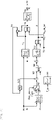
Fig. 1 is a schematic view illustrating a configuration example of acontroller 50 for the internal combustion engine. - The
controller 50 controls driving of aninternal combustion engine 10 exemplified as a gasoline engine or a diesel engine. A description will hereinafter be made on a case where theinternal combustion engine 10 is the diesel engine as an example. - The
internal combustion engine 10 includes plural cylinders, and a piston reciprocates in each of the cylinders. The piston reciprocates once every time a crankshaft makes one rotation in conjunction with the rotation of the crankshaft. Theinternal combustion engine 10 includes a fuel injector corresponding to each of the cylinders. The fuel injector primarily injects fuel in an intake stroke and generates air-fuel mixture in the cylinder. The generated air-fuel mixture is ignited spontaneously in a compression stroke, is expanded, and causes the crankshaft to rotate. Thecontroller 50 controls driving of the fuel injector. Power of theinternal combustion engine 10 is transmitted to atransmission 21 via the crankshaft. Thetransmission 21 includes a stepped or stepless transmission mechanism, changes a rotational frequency of the crankshaft at a specified gear ratio, and transmits the changed rotational frequency to drive wheels. - The
internal combustion engine 10 includes acrank angle sensor 15 that detects a rotation angle of the crankshaft. A sensor signal of thecrank angle sensor 15 is input to thecontroller 50. Based on the input sensor signal, thecontroller 50 detects the rotational frequency of the crankshaft, that is, a speed of the internal combustion engine. Thetransmission 21 includes avehicle speed sensor 17 that detects a vehicle speed. A sensor signal of thevehicle speed sensor 17 is input to thecontroller 50. Based on the input sensor signal, thecontroller 50 detects the vehicle speed. - The
controller 50 is partially or entirely constructed of a microcomputer, a microprocessor, or the like, for example. Alternatively, thecontroller 50 may partially or entirely be constructed of one whose firmware and the like can be updated, or may partially or entirely be a program module or the like that is executed by a command from a central processing unit (CPU) or the like, for example. -
Fig. 1 illustrates a functional configuration of thecontroller 50. Thecontroller 50 includes a start-time target enginespeed setting section 51, an idle rotation controltorque calculation section 53, a driver requesttorque calculation section 55, a targettorque calculation section 57, and anengine control section 59. More specifically, each of these sections may be a function that is implemented when the microcomputer or the like executes a program. - In addition to the above, the
controller 50 includes one or plural communication interfaces and drive circuits. Furthermore, thecontroller 50 includes a storage section, which is not illustrated, such as read only memory (ROM) and random access memory (RAM). The storage section stores the program that is executed by the microcomputer or the like, various parameters used for arithmetic processing, acquired information, arithmetic results, and the like. - As described above, the
controller 50 can acquire the sensor signals of thecrank angle sensor 15 and thevehicle speed sensor 17. Thecontroller 50 can also acquire information on an operation amount of a brake pedal (hereinafter also referred to as a "brake operation amount") br, a position of a shift lever (hereinafter also referred to as a "shift position") ge, an operation amount of a clutch pedal (hereinafter also referred to as a "clutch operation amount") cl, and an operation amount of an accelerator pedal (hereinafter also referred to as an "accelerator operation amount") ac. For example, these types of the information can be acquired on the basis of sensor signals of abrake pedal sensor 31, a shift position sensor 33, aclutch pedal sensor 35, and anaccelerator pedal sensor 37. - When detecting a vehicle starting operation, the start-time target engine
speed setting section 51 sets a start-time target engine speed N3 of theinternal combustion engine 10 in a period until a vehicle speed V reaches a specified cancellation threshold value V0, which is set in advance. In this embodiment, the start-time target enginespeed setting section 51 sets the start-time target engine speed N3 on the basis of a basic start-time target engine speed N2 and a surplus engine speed N21. - The basic start-time target engine speed N2 is a target value of the engine speed that is set on the basis of the accelerator operation amount ac and the clutch operation amount cl in the case where the vehicle is set in a starting control mode. In order to improve startability at the time when the vehicle starting operation is performed and then the accelerator pedal is depressed, the start-time target engine
speed setting section 51 is configured to increase the basic start-time target engine speed N2 on the basis of the accelerator operation amount ac and the clutch operation amount cl. For example, the start-time target enginespeed setting section 51 increases the basic start-time target engine speed N2 as the accelerator operation amount ac is increased and as the clutch operation amount cl is reduced. - The start-time target engine
speed setting section 51 sets the starting control mode to be on on the basis of the brake operation amount br, the shift position ge, and the clutch operation amount cl, for example. More specifically, in the case where the shift position ge is in a gear-in state while the clutch is disengaged, and the brake pedal is released from being depressed, the start-time target enginespeed setting section 51 detects that the vehicle starting operation is about to be performed, and sets the starting control mode to be on. - Then, after setting of the starting control mode to be on, when the vehicle speed V reaches the specified cancellation threshold value V0, when the brake pedal is depressed, or the like, the start-time target engine
speed setting section 51 sets the starting control mode to be off. The cancellation threshold value V0 at which the starting control mode is set to be off is a threshold value used to determine that the vehicle in a stopped state reaches a specified vehicle speed and the vehicle starting operation is thus completed. - The surplus engine speed N21 is the surplus engine speed N21 that corresponds to differential torque T4 at the time when a sum T1 + T2 of idle rotation control torque T2 and basic driver request torque T1 exceeds specified upper limit torque T3. The differential torque T4 is acquired by subtracting the upper limit torque T3 from the sum T1 + T2 of the torque. That is, the surplus engine speed N21 is an engine speed to be reduced in order to limit the sum of the output torque (T2) and the output torque (T1) to be equal to or lower than the upper limit torque T3. The output torque (T2) is torque in a case where the
internal combustion engine 10 is driven at the start-time target engine speed N3 without any limitation. The output torque (T1) is torque in a case where theinternal combustion engine 10 is driven on the basis of the accelerator operation amount ac without any limitation. The start-time target enginespeed setting section 51 sets, as the start-time target engine speed N3, a value that is acquired by subtracting the surplus engine speed N21 from the basic start-time target engine speed N2. - The idle rotation control
torque calculation section 53 sets the idle rotation control torque T2 of theinternal combustion engine 10 on the basis of a value N4 of higher one of a target idle engine speed N1 and the start-time target engine speed N3 of theinternal combustion engine 10. The target idle engine speed N1 is a target value of the engine speed in an idle state of theinternal combustion engine 10. For example, the target idle engine speed N1 is set in advance according to an ambient temperature T_a, and is stored in the storage section. The idle rotation controltorque calculation section 53 calculates the target idle engine speed N1 on the basis of the ambient temperature T_a that is detected on the basis of a sensor signal of an ambient temperature sensor or the like. - The idle rotation control
torque calculation section 53 performs a proportional-integral (PI) operation such that a difference acquired by subtracting a current engine speed N of theinternal combustion engine 10 from the value N4 of the higher one of the above converges to zero, and thereby calculates the idle rotation control torque T2. In this embodiment, in order to prevent target torque T7 from finally exceeding the upper limit torque T3, the idle rotation controltorque calculation section 53 sets, as the idle rotation control torque T2, a value of lower one of the basic idle rotation control torque T2', which is acquired by performing the PI operation, and the upper limit torque T3. - Based on the basic driver request torque T1 that corresponds to the accelerator operation amount ac, the driver request
torque calculation section 55 sets driver request torque T6 of theinternal combustion engine 10 such that a change speed does not exceed a specified threshold value. That is, the driver requesttorque calculation section 55 executes damping processing at the time of setting the driver request torque T6. The damping processing may be executed on the basis of a lowpass filter, for example. In this way, a shock at the time of depressing the accelerator pedal can be alleviated. However, it is preferred that the driver requesttorque calculation section 55 does not execute the damping processing when the driver request torque is reduced. This is to avoid timing to reduce the vehicle drive torque from being delayed. - In the case where the basic driver request torque T1 is higher than a value (T3 - T2) of remaining torque that is acquired by subtracting the idle rotation control torque T2 from the upper limit torque T3, the driver request
torque calculation section 55 sets the driver request torque T6 on the basis of the value (T3 - T2) of the remaining torque such that the final target torque T7 does not exceed the upper limit torque T3. It is possible to reliably prevent the final target torque T7 from exceeding the upper limit torque T3 by using the value (T3 - T2) of the remaining torque as an input value prior to the damping processing. - The target
torque calculation section 57 sets the target torque T7 by adding the idle rotation control torque T2, which is calculated by the idle rotation controltorque calculation section 53, and the driver request torque T6, which is calculated by the driver requesttorque calculation section 55. Since the calculated target torque T7 is set with the upper limit torque T3 as an upper limit, the shock caused by depressing the accelerator pedal at the starting of the vehicle is alleviated. - The
engine control section 59 controls theinternal combustion engine 10 on the basis of the target torque T7, which is set by the targettorque calculation section 57. More specifically, theengine control section 59 causes theinternal combustion engine 10 to output torque that corresponds to the target torque T7 by controlling a fuel injection amount, fuel injection timing, an air-fuel ratio, and the like of theinternal combustion engine 10. - The description has been made so far on the configuration example of the
controller 50 for the internal combustion engine according to this embodiment. A description will hereinafter be made on an operation example of thecontroller 50 for the internal combustion engine according to this embodiment. -
Fig. 2 is an explanatory view illustrating a control logic of torque control that is executed by thecontroller 50. A description will firstly be made on an arithmetic logic of the idle rotation control torque T2. First, the basic start-time target engine speed N2, which is calculated on the basis of the accelerator operation amount ac and the clutch operation amount cl, is calculated. In the case where the starting operation is detected in the stopped state of the vehicle and a starting control mode Req_sa is set to be on, the above basic start-time target engine speed N2 is set as the basic start-time target engine speed N2 as is. On the other hand, in the case where the starting control mode Req_sa is set to be off, the basic start-time target engine speed N2 is set to zero. - Next, the surplus engine speed N21 is subtracted from the basic start-time target engine speed N2 to calculate the start-time target engine speed N3. As described above, the surplus engine speed N21 is the engine speed that should be subtracted in order to limit the final target torque T7 to be equal to or lower than the upper limit torque T3. Next, the target idle engine speed N1, which is set according to the ambient temperature T_a, is compared to the calculated start-time target engine speed N3. Then, the PI operation is performed such that the difference acquired by subtracting the current engine speed N of the
internal combustion engine 10 from the value N4 of the higher one of the above converges to zero. Consequently, basic idle rotation control torque T2' is calculated. - Then, a value of lower one of the basic idle rotation control torque T2' and the upper limit torque T3 is set as the idle rotation control torque T2 such that the final target torque T7 does not exceed the upper limit torque T3, which is set in advance.
- Here, the surplus engine speed N21 is calculated by subjecting the differential torque T4 to a feedback operation, and the differential torque T4 is acquired by subtracting a value T5 of lower one of the value (T3 - T2), which is acquired by subtracting the idle rotation control torque T2 from the upper limit torque T3, and the basic driver request torque T1, which is calculated on the basis of the accelerator operation amount ac and the engine speed N of the
internal combustion engine 10, from the basic driver request torque T1. - A description will be made on an arithmetic logic of the driver request torque T6. First, the basic driver request torque T1 is calculated on the basis of the accelerator operation amount ac and the engine speed N of the
internal combustion engine 10. Next, the basic driver request torque T1 is compared to the value (T3 - T2), which is acquired by subtracting the idle rotation control torque T2 limited by the upper limit torque T3, such that a sum of the driver request torque and the idle rotation control torque falls within the upper limit torque (T3), and the value T5 of the lower one thereof is subjected to the damping processing. In this way, the driver request torque T6 is calculated. - The idle rotation control torque T2 and the driver request torque T6, which are calculated just as described, are added, and the final target torque T7 is thereby calculated. That is, the
controller 50 according to this embodiment limits the idle rotation control torque T2 instead of the driver request torque T6 in order to limit the final target torque T7 to be equal to or lower than the upper limit torque T3. In addition, thecontroller 50 executes, in advance, the subtraction processing of the start-time target engine speed N4, which is used to calculate the idle rotation control torque T2, instead of calculating the idle rotation control torque T2 and the driver request torque T6, adding these to calculate the target torque T7, and thereafter, executing subtraction processing to suppress the target torque T7 to the upper limit torque T3. In this way, it is possible to suppress the timing to reduce the torque output from theinternal combustion engine 10 from being delayed. -
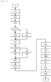
Fig. 3 is a flowchart of the torque control that is executed by thecontroller 50 for the internal combustion engine on the basis of the control logic illustrated inFig. 2 . - First, the driver request
torque calculation section 55 calculates the basic driver request torque T1 on the basis of the accelerator operation amount ac and the engine speed N of the internal combustion engine 10 (step S11). Next, the start-time target enginespeed setting section 51 sets the target idle engine speed N1 on the basis of the ambient temperature T_a (step S13). Then, the start-time target enginespeed setting section 51 acquires the setting information of the starting control mode Req_sa (step S15), and determines whether the starting control mode Req_sa is set to be on (step S17). - If the starting control mode Req_sa is set to be on (S17/Yes), the start-time target engine
speed setting section 51 sets the basic start-time target engine speed N2 on the basis of the accelerator operation amount ac and the clutch operation amount cl (step S19). On the other hand, if the starting control mode Req_sa is set to be off (S17/No), the start-time target enginespeed setting section 51 sets the basic start-time target engine speed N2 to zero (step S21) . - Next, the driver request
torque calculation section 55 calculates the upper limit torque T3 on the basis of the parameters such as the engine speed N of the internal combustion engine 10 (step S23). Then, the idle rotation controltorque calculation section 53 calculates the basic idle rotation control torque T2' at the time of performing the PI operation such that the value acquired by subtracting the current engine speed N of theinternal combustion engine 10 from the basic start-time target engine speed N2 converges to zero, and determines whether the sum of the basic idle rotation control torque T2' and the basic driver request torque T1 exceeds the upper limit torque T3 (step S25). - If the sum of the basic driver request torque T1 and the basic idle rotation control torque T2' exceeds the upper limit torque T3 (S25/Yes), the idle rotation control
torque calculation section 53 calculates the differential torque T4 ((T1 + T2) - T3) (step S27). On the other hand, if the sum of the basic driver request torque T1 and the basic idle rotation control torque T2' does not exceed the upper limit torque T3 (S25/No), the idle rotation controltorque calculation section 53 sets the differential torque T4 to zero (step S29) . - In the control logic illustrated in
Fig. 2 , the processing in step S25 to step S29 corresponds to a portion in which the value T5 of the lower one of the value (T3 - T2), which is acquired by subtracting the idle rotation control torque T2 (= MIN(T2', T3)) as the value of the lower one of the upper limit torque T3 and the basic idle rotation control torque T2' from the upper limit torque T3, and the basic driver request torque T1 is subtracted from the basic driver request torque T1, so as to calculate the differential torque T4. - Next, the idle rotation control
torque calculation section 53 performs the feedback operation on the basis of the calculated differential torque T4, and calculates the surplus engine speed N21 (step S31). Then, the start-time target enginespeed setting section 51 subtracts the surplus engine speed N21 from the basic start-time target engine speed N2, which is calculated in step S19 or S21, and sets the start-time target engine speed N3 (step S33). Next, the idle rotation controltorque calculation section 53 calculates the value N4 of the higher one of the start-time target engine speed N3 and the target idle engine speed N1 (step S35). - Next, the idle rotation control
torque calculation section 53 performs the PI operation such that the value acquired by subtracting the current engine speed N of theinternal combustion engine 10 from the above calculated value N4 converges to zero, and updates the basic idle rotation control torque T2' (step S37). Then, the idle rotation controltorque calculation section 53 compares the basic idle rotation control torque T2' to the upper limit torque T3, and calculates the value of the lower one thereof as the idle rotation control torque T2 (step S39). - Next, the driver request
torque calculation section 55 compares the basic driver request torque T1 to the value (T3 - T2), which is acquired by subtracting the idle rotation control torque T2 from the upper limit torque T3, and calculates the value T5 of the lower one thereof (step S41). Then, the driver requesttorque calculation section 55 executes the damping processing of the above value T5 on the basis of the lowpass filter, and calculates the driver request torque T6 (step S43). - Next, the target
torque calculation section 57 adds the idle rotation control torque T2, which is calculated in step S39, and the driver request torque T6, which is calculated in step S43, to set the final target torque T7 (step S45). The set target torque T7 is used as the control parameter for theengine control section 59, and the torque output from theinternal combustion engine 10 is thereby controlled. Thecontroller 50 repeatedly executes the processing in step S11 to step S45 so far, and thereby executes the torque control for theinternal combustion engine 10 at the starting of the vehicle. - Just as described, the
controller 50 limits the idle rotation control torque T2 instead of the driver request torque T6, and calculates the final target torque T7. As a result, at a time point at which the vehicle speed V reaches the specified cancellation threshold value V0 and the start-time target engine speed is set to zero, the idle rotation control torque T2 is avoided from reaching the upper limit torque T3, and the driver request torque T6 is thereby avoided from being limited to zero. Accordingly, along with the damping processing of the driver request torque T6, the reduction in the target torque T7 at the time of switching the starting control mode from on to off is alleviated. Therefore, worsening of ride comfort can be suppressed. - Next, a description will be made on operational effects exerted by the
controller 50 for the internal combustion engine according to this embodiment. - First, a description will be made on a reference example in which the target torque T7 is significantly reduced at the time of switching the starting control mode from on to off.
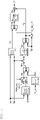
Fig. 4 is an explanatory view illustrating a control logic of torque control according to the reference example, andFig. 5 is an explanatory chart illustrating transition of the target torque T7 in the case where starting control is executed on the basis of the control logic. - As illustrated in
Fig. 4 , in the control logic according to the reference example, in the case where the sum of the basic driver request torque T1 and the idle rotation control torque T2 exceeds the upper limit torque T3, processing to subtract the surplus engine speed (N21), which corresponds to the differential torque (T4), from the basic start-time target engine speed N2 in advance is not executed. - As illustrated in
Fig. 5 , the brake pedal is depressed, the shift lever is in a neutral state, the clutch that connects theinternal combustion engine 10 to thetransmission 21 is engaged, and the accelerator pedal is released. In such a state, the idle rotation control torque T2, which is calculated on the basis of the target idle engine speed N1, is set as the target torque T7 (a period up to time ti1). - It is assumed that the clutch is disengaged at the time ti1, that the shift position is switched from the neutral state to the gear-in state at time ti2, and that the brake pedal is released at time ti3. In such a case, in order to improve responsiveness at the time of depressing the accelerator pedal, the basic start-time target engine speed N2 is set to be a higher value than the target idle engine speed N1. In conjunction therewith, the idle rotation control torque T2, which is calculated on the basis of the basic start-time target engine speed N2, is set as the target torque T7. Since the idle rotation control torque T2 is subjected to the PI operation, the idle rotation control torque T2 is gradually increased at the time ti3 onward, and the engine speed N of the
internal combustion engine 10 is also gradually increased. - When the accelerator pedal is depressed at time ti4, the basic start-time target engine speed N2, which is set according to the accelerator operation amount ac, is further increased. In conjunction therewith, the idle rotation control torque T2 is increased. In addition, the basic driver request torque T1, which is set on the basis of the accelerator operation amount ac and the engine speed N of the
internal combustion engine 10, is increased, and the driver request torque T6 is increased. Accordingly, the target torque T7, which is acquired by adding the idle rotation control torque T2 and the driver request torque T6, is also increased. Since the driver request torque T6 has been subjected to the damping processing, the driver request torque T6 and the target torque T7 are gradually increased. - However, in a period from the time ti4 to time ti5, the idle rotation control torque T2 does not reach the upper limit torque T3. Accordingly, while the idle rotation control torque T2 is not limited, the basic driver request torque T1 is limited by the difference (T3 - T2) between the upper limit torque T3 and the idle rotation control torque T2 such that the sum of the driver request torque and the idle rotation control torque falls within the upper limit torque T3.
- At the time ti5, the clutch starts being shifted to a riding state, which further increases the basic start-time target engine speed N2. Consequently, the idle rotation control torque T2 is increased. Thus, the driver request torque T6 is reduced to limit the target torque T7 to the upper limit torque T3. Then, when the idle rotation control torque T2 reaches the upper limit torque T3 at time ti6, the driver request torque T6 is limited to zero onward.
- When the vehicle speed V reaches the specified cancellation threshold value V0 in such a state at time ti7, the starting control mode is canceled, and the basic start-time target engine speed N2 is returned to zero. As a result, while the idle rotation control torque T2 becomes zero, the driver request torque T6, which is subjected to the damping processing, is gradually increased until reaching the upper limit torque T3. Since the driver request torque T6, which is subjected to the damping processing, is increased over time, the target torque T7 is significantly reduced immediately after the time ti7, at which the starting control mode is canceled.
-
Fig. 6 is an explanatory chart illustrating the transition of the target torque T7 in the case where thecontroller 50 for theinternal combustion engine 10 according to this embodiment executes the starting control. - Up to the time ti4, at which the accelerator pedal is depressed, each of the idle rotation control torque T2, the driver request torque T6, and the target torque T7 shows similar transition to that in the reference example. Here, since the idle rotation control torque T2 is subjected to the PI operation, the idle rotation control torque T2 is gradually increased at the time ti3 onward, and the engine speed N of the
internal combustion engine 10 is also gradually increased. - When the accelerator pedal is depressed at the time ti4, the basic driver request torque T1, which is set on the basis of the accelerator operation amount ac and the engine speed N of the
internal combustion engine 10, is increased, and the driver request torque T6 is increased. Accordingly, the target torque T7, which is acquired by adding the idle rotation control torque T2 and the driver request torque T6, is also increased. Since the driver request torque T6 has been subjected to the damping processing, the driver request torque T6 and the target torque T7 are gradually increased. Here, when the idle rotation control torque T2 is increased due to the increase in the accelerator operation amount ac, the sum of the basic driver request torque T1 and the idle rotation control torque T2 exceeds the upper limit torque T3. For this reason, thecontroller 50 according to this embodiment does not increase the idle rotation control torque T2. - In addition, even when the clutch starts being shifted to the riding state at the time ti5, the
controller 50 according to this embodiment does not increase the idle rotation control torque T2. As a result, in the period from the time ti4 to the time ti5, the target torque T7 is lower than the upper limit torque T3, and the driver request torque T6 is set to the value acquired by subjecting the basic driver request torque T1 to the damping processing. - Thereafter, when the accelerator pedal is further depressed at time ti8, the basic driver request torque T1 is further increased. In conjunction therewith, the driver request torque T6 and the target torque T7 also start being increased. Since the clutch is brought into the riding state at the time ti8, the engine speed N of the
internal combustion engine 10 is reduced once. However, due to the increase in the basic driver request torque T1, the sum of the basic driver request torque T1 and the idle rotation control torque T2 reaches the upper limit torque T3. Accordingly, at time ti9, at which the target torque T7 reaches the upper limit torque T3, onward, the driver request torque T6 is set not on the basis of the basic driver request torque T1 but on the basis of the value (T5) acquired by subtracting the idle rotation control torque T2 from the upper limit torque T3. In this way, the final target torque T7 is limited to the upper limit torque T3. - Thereafter, while the clutch is shifted from the riding state to the engaged state, the surplus engine speed N21, which corresponds to the differential torque (T4) acquired by subtracting the upper limit torque T3 from the sum (T1 + T2) of the basic driver request torque T1 and the idle rotation control torque T2, is subtracted from the basic start-time target engine speed N2, and the idle rotation control torque T2 is calculated. Accordingly, the idle rotation control torque T2 does not reach the upper limit torque T3, and the driver request torque T6 is not limited to zero. Thus, a difference between two types of the request torque is set not to be significant.
- Then, when the vehicle speed V reaches the specified cancellation threshold value V0 at time ti10, the starting control mode is canceled, and the basic start-time target engine speed N2 is returned to zero. As a result, while the idle rotation control torque T2 becomes zero, the driver request torque T6, which is subjected to the damping processing, is gradually increased to the upper limit torque T3. However, in this embodiment, the idle rotation control torque T2 is limited to a lower value than the upper limit torque T3, and the driver request torque T6 is not limited to zero. Accordingly, although the driver request torque T6, which is subjected to the damping processing, is increased over time, the reduction in the target torque T7 immediately after the time ti7, at which the starting control mode is canceled, is alleviated. Thus, it is possible to suppress worsening of the ride comfort at the starting of the vehicle.
- As it has been described so far, in the case where the target torque T7, which is acquired by adding the idle rotation control torque T2 and the driver request torque T6, exceeds the upper limit torque T3, at the starting of the vehicle, the
controller 50 for the internal combustion engine according to this embodiment limits the start-time target engine speed N3, which is used to calculate the idle rotation control torque T2. Thus, while the idle rotation control torque T2 reaches the upper limit torque T3, it is possible to prevent the driver request torque T6 from being limited to zero. In this way, it is possible to alleviate the reduction in the target torque T7 at the time when the vehicle speed V reaches the cancellation threshold value V0 and the starting control mode is canceled. As a result, it is possible to suppress worsening of the ride comfort at the starting of the vehicle. - The detailed description has been made so far on the preferred embodiment of the present invention with reference to the accompanying drawings. However, the present invention is not limited to such an example. It is obvious that a person who has basic knowledge in the technical field to which the present invention pertains could have easily arrived at various modification examples and application examples that fall within the scope of the technical idea described in the claims. It is understood that those naturally fall within the technical scope of the present invention.
-
- 10:
- Engine
- 50:
- Controller
- 51:
- Start-time target engine speed setting section
- 53:
- Idle rotation control torque calculation section
- 55:
- Driver request torque calculation section
- 57:
- Target torque calculation section
- 59:
- Engine control section
Claims (3)
- A controller for an internal combustion engine, the controller comprising:a start-time target engine speed setting section (51) that, when detecting a starting operation of a vehicle, sets a start-time target engine speed (N3) of an internal combustion engine (10) on the basis of a basic start-time target engine speed (N2) corresponding to an accelerator operation amount by a driver in a period until a vehicle speed reaches a specified cancellation threshold value;an idle rotation control torque calculation section (53) that sets idle rotation control torque (T2) of the internal combustion engine (10) on the basis of a value of higher one of a target idle engine speed (N1) and the start-time target engine speed (N3) of the internal combustion engine (10);a driver request torque calculation section (55) that sets driver request torque (T6) of the internal combustion engine (10) on the basis of basic driver request torque (T1) corresponding to the accelerator operation amount by the driver such that a change speed does not exceed a specified threshold value;a target torque calculation section (57) that adds the idle rotation control torque (T2) to the driver request torque (T6) and sets target torque (T7) with specified upper limit torque (T3) as an upper limit; andan engine control section (59) that controls the internal combustion engine (10) on the basis of the target torque (T7), whereinin the case where a sum (T2 + T1) of the idle rotation control torque (T2) and the basic driver request torque (T1) exceeds the upper limit torque (T3), the idle rotation control torque calculation section (53) sets the idle rotation control torque (T2), from which at least differential torque (T4) between the sum (T2 + T1) and the upper limit torque (T3) is subtracted.
- The controller for the internal combustion engine according to claim 1, wherein
the start-time target engine speed setting section (51) sets the start-time target engine speed (N3) by subtracting a surplus engine speed (N21) that corresponds to the differential torque (T4) from the basic start-time target engine speed (N2). - The controller for the internal combustion engine according to claim 1 or 2, wherein
the start-time target engine speed setting section (51) sets the basic start-time target engine speed (N2) to zero when the vehicle speed reaches the specified cancellation threshold value.
Applications Claiming Priority (2)
| Application Number | Priority Date | Filing Date | Title |
|---|---|---|---|
| JP2019214838 | 2019-11-28 | ||
| PCT/JP2020/035372 WO2021106327A1 (en) | 2019-11-28 | 2020-09-18 | Control device for internal combustion engine |
Publications (3)
| Publication Number | Publication Date |
|---|---|
| EP4067637A1 true EP4067637A1 (en) | 2022-10-05 |
| EP4067637A4 EP4067637A4 (en) | 2023-01-18 |
| EP4067637B1 EP4067637B1 (en) | 2025-02-26 |
Family
ID=76128885
Family Applications (1)
| Application Number | Title | Priority Date | Filing Date |
|---|---|---|---|
| EP20891541.3A Active EP4067637B1 (en) | 2019-11-28 | 2020-09-18 | Control device for internal combustion engine |
Country Status (4)
| Country | Link |
|---|---|
| EP (1) | EP4067637B1 (en) |
| JP (1) | JP7342144B2 (en) |
| ES (1) | ES3028421T3 (en) |
| WO (1) | WO2021106327A1 (en) |
Family Cites Families (4)
| Publication number | Priority date | Publication date | Assignee | Title |
|---|---|---|---|---|
| JP4282151B2 (en) * | 1999-06-09 | 2009-06-17 | 富士重工業株式会社 | Engine control device |
| US7051517B2 (en) * | 2003-07-24 | 2006-05-30 | General Motors Corporation | Apparatus and method for electronic throttle control power management enhancements |
| JP4349258B2 (en) * | 2004-10-20 | 2009-10-21 | 株式会社デンソー | Torque control device for vehicle |
| JP2016200093A (en) * | 2015-04-13 | 2016-12-01 | いすゞ自動車株式会社 | Starting assistance device |
-
2020
- 2020-09-18 ES ES20891541T patent/ES3028421T3/en active Active
- 2020-09-18 JP JP2021561182A patent/JP7342144B2/en active Active
- 2020-09-18 WO PCT/JP2020/035372 patent/WO2021106327A1/en not_active Ceased
- 2020-09-18 EP EP20891541.3A patent/EP4067637B1/en active Active
Also Published As
| Publication number | Publication date |
|---|---|
| EP4067637B1 (en) | 2025-02-26 |
| JP7342144B2 (en) | 2023-09-11 |
| ES3028421T3 (en) | 2025-06-19 |
| WO2021106327A1 (en) | 2021-06-03 |
| JPWO2021106327A1 (en) | 2021-06-03 |
| EP4067637A4 (en) | 2023-01-18 |
Similar Documents
| Publication | Publication Date | Title |
|---|---|---|
| US9656676B2 (en) | Vehicle travel control device | |
| CN107878449B (en) | Vehicle control device | |
| US9656670B2 (en) | Vehicle travel control device | |
| US10006391B2 (en) | Engine start control device | |
| EP2597290A1 (en) | Automatic stop device and automatic stop method for internal combustion engine | |
| KR101871086B1 (en) | Vehicle control apparatus | |
| US8996264B2 (en) | Control device for continuously variable transmission and control method for continuously variable transmission | |
| JP2011201415A (en) | Vehicle drive controller | |
| EP4067637B1 (en) | Control device for internal combustion engine | |
| KR20150036339A (en) | A method when driving a vehicle and swithching to higher gear, a computer program for the method, a system enabling the method and a vehicle for it | |
| JP5741463B2 (en) | Vehicle abnormality determination device | |
| JP2004155419A (en) | Vehicle speed control method | |
| US12233850B2 (en) | Controller and control method for hybrid electric vehicle | |
| JP2009013802A (en) | Fuel injection control device and fuel injection control system | |
| JP4692353B2 (en) | Torque control device for internal combustion engine | |
| JP2006161561A (en) | Fuel injection control device for internal combustion engine | |
| JP2010249190A (en) | Control device for automatic transmission for vehicle | |
| JP2009047032A (en) | Control device for vehicle shift | |
| JP4051779B2 (en) | Vehicle speed control device | |
| CN106795825B (en) | Method for interrupting fuel injection in internal combustion engine | |
| US20250242793A1 (en) | Stabilization factors and approaches in real-time vehicle powertrain mode optimization | |
| JP4738473B2 (en) | Torque control device for internal combustion engine | |
| JP2016200093A (en) | Starting assistance device | |
| JP2008215198A (en) | Control device and control method for internal combustion engine | |
| CN110494639A (en) | Method for controlling the torque of spark ignition engine |
Legal Events
| Date | Code | Title | Description |
|---|---|---|---|
| STAA | Information on the status of an ep patent application or granted ep patent |
Free format text: STATUS: THE INTERNATIONAL PUBLICATION HAS BEEN MADE |
|
| PUAI | Public reference made under article 153(3) epc to a published international application that has entered the european phase |
Free format text: ORIGINAL CODE: 0009012 |
|
| STAA | Information on the status of an ep patent application or granted ep patent |
Free format text: STATUS: REQUEST FOR EXAMINATION WAS MADE |
|
| 17P | Request for examination filed |
Effective date: 20220628 |
|
| AK | Designated contracting states |
Kind code of ref document: A1 Designated state(s): AL AT BE BG CH CY CZ DE DK EE ES FI FR GB GR HR HU IE IS IT LI LT LU LV MC MK MT NL NO PL PT RO RS SE SI SK SM TR |
|
| REG | Reference to a national code |
Ref country code: DE Free format text: PREVIOUS MAIN CLASS: F02D0029000000 Ref country code: DE Ref legal event code: R079 Ref document number: 602020046991 Country of ref document: DE Free format text: PREVIOUS MAIN CLASS: F02D0029000000 Ipc: F02D0029020000 |
|
| A4 | Supplementary search report drawn up and despatched |
Effective date: 20221219 |
|
| RIC1 | Information provided on ipc code assigned before grant |
Ipc: F02D 41/14 20060101ALN20221213BHEP Ipc: F02D 31/00 20060101ALI20221213BHEP Ipc: F02D 11/10 20060101ALI20221213BHEP Ipc: B60W 30/18 20120101ALI20221213BHEP Ipc: F02D 41/06 20060101ALI20221213BHEP Ipc: F02D 29/02 20060101AFI20221213BHEP |
|
| DAV | Request for validation of the european patent (deleted) | ||
| DAX | Request for extension of the european patent (deleted) | ||
| P01 | Opt-out of the competence of the unified patent court (upc) registered |
Effective date: 20230530 |
|
| GRAP | Despatch of communication of intention to grant a patent |
Free format text: ORIGINAL CODE: EPIDOSNIGR1 |
|
| STAA | Information on the status of an ep patent application or granted ep patent |
Free format text: STATUS: GRANT OF PATENT IS INTENDED |
|
| RIC1 | Information provided on ipc code assigned before grant |
Ipc: F02D 41/14 20060101ALN20241010BHEP Ipc: F02D 31/00 20060101ALI20241010BHEP Ipc: F02D 11/10 20060101ALI20241010BHEP Ipc: B60W 30/18 20120101ALI20241010BHEP Ipc: F02D 41/06 20060101ALI20241010BHEP Ipc: F02D 29/02 20060101AFI20241010BHEP |
|
| INTG | Intention to grant announced |
Effective date: 20241023 |
|
| GRAS | Grant fee paid |
Free format text: ORIGINAL CODE: EPIDOSNIGR3 |
|
| GRAA | (expected) grant |
Free format text: ORIGINAL CODE: 0009210 |
|
| STAA | Information on the status of an ep patent application or granted ep patent |
Free format text: STATUS: THE PATENT HAS BEEN GRANTED |
|
| AK | Designated contracting states |
Kind code of ref document: B1 Designated state(s): AL AT BE BG CH CY CZ DE DK EE ES FI FR GB GR HR HU IE IS IT LI LT LU LV MC MK MT NL NO PL PT RO RS SE SI SK SM TR |
|
| REG | Reference to a national code |
Ref country code: GB Ref legal event code: FG4D |
|
| REG | Reference to a national code |
Ref country code: CH Ref legal event code: EP |
|
| REG | Reference to a national code |
Ref country code: DE Ref legal event code: R096 Ref document number: 602020046991 Country of ref document: DE |
|
| REG | Reference to a national code |
Ref country code: IE Ref legal event code: FG4D |
|
| REG | Reference to a national code |
Ref country code: ES Ref legal event code: FG2A Ref document number: 3028421 Country of ref document: ES Kind code of ref document: T3 Effective date: 20250619 |
|
| REG | Reference to a national code |
Ref country code: NL Ref legal event code: MP Effective date: 20250226 |
|
| PG25 | Lapsed in a contracting state [announced via postgrant information from national office to epo] |
Ref country code: RS Free format text: LAPSE BECAUSE OF FAILURE TO SUBMIT A TRANSLATION OF THE DESCRIPTION OR TO PAY THE FEE WITHIN THE PRESCRIBED TIME-LIMIT Effective date: 20250526 |
|
| PG25 | Lapsed in a contracting state [announced via postgrant information from national office to epo] |
Ref country code: FI Free format text: LAPSE BECAUSE OF FAILURE TO SUBMIT A TRANSLATION OF THE DESCRIPTION OR TO PAY THE FEE WITHIN THE PRESCRIBED TIME-LIMIT Effective date: 20250226 |
|
| PG25 | Lapsed in a contracting state [announced via postgrant information from national office to epo] |
Ref country code: PL Free format text: LAPSE BECAUSE OF FAILURE TO SUBMIT A TRANSLATION OF THE DESCRIPTION OR TO PAY THE FEE WITHIN THE PRESCRIBED TIME-LIMIT Effective date: 20250226 |
|
| REG | Reference to a national code |
Ref country code: LT Ref legal event code: MG9D |
|
| PG25 | Lapsed in a contracting state [announced via postgrant information from national office to epo] |
Ref country code: NO Free format text: LAPSE BECAUSE OF FAILURE TO SUBMIT A TRANSLATION OF THE DESCRIPTION OR TO PAY THE FEE WITHIN THE PRESCRIBED TIME-LIMIT Effective date: 20250526 Ref country code: IS Free format text: LAPSE BECAUSE OF FAILURE TO SUBMIT A TRANSLATION OF THE DESCRIPTION OR TO PAY THE FEE WITHIN THE PRESCRIBED TIME-LIMIT Effective date: 20250626 |
|
| PG25 | Lapsed in a contracting state [announced via postgrant information from national office to epo] |
Ref country code: NL Free format text: LAPSE BECAUSE OF FAILURE TO SUBMIT A TRANSLATION OF THE DESCRIPTION OR TO PAY THE FEE WITHIN THE PRESCRIBED TIME-LIMIT Effective date: 20250226 |
|
| PG25 | Lapsed in a contracting state [announced via postgrant information from national office to epo] |
Ref country code: HR Free format text: LAPSE BECAUSE OF FAILURE TO SUBMIT A TRANSLATION OF THE DESCRIPTION OR TO PAY THE FEE WITHIN THE PRESCRIBED TIME-LIMIT Effective date: 20250226 |
|
| PG25 | Lapsed in a contracting state [announced via postgrant information from national office to epo] |
Ref country code: PT Free format text: LAPSE BECAUSE OF FAILURE TO SUBMIT A TRANSLATION OF THE DESCRIPTION OR TO PAY THE FEE WITHIN THE PRESCRIBED TIME-LIMIT Effective date: 20250626 Ref country code: LV Free format text: LAPSE BECAUSE OF FAILURE TO SUBMIT A TRANSLATION OF THE DESCRIPTION OR TO PAY THE FEE WITHIN THE PRESCRIBED TIME-LIMIT Effective date: 20250226 |
|
| PG25 | Lapsed in a contracting state [announced via postgrant information from national office to epo] |
Ref country code: BG Free format text: LAPSE BECAUSE OF FAILURE TO SUBMIT A TRANSLATION OF THE DESCRIPTION OR TO PAY THE FEE WITHIN THE PRESCRIBED TIME-LIMIT Effective date: 20250226 Ref country code: GR Free format text: LAPSE BECAUSE OF FAILURE TO SUBMIT A TRANSLATION OF THE DESCRIPTION OR TO PAY THE FEE WITHIN THE PRESCRIBED TIME-LIMIT Effective date: 20250527 |
|
| REG | Reference to a national code |
Ref country code: AT Ref legal event code: MK05 Ref document number: 1770818 Country of ref document: AT Kind code of ref document: T Effective date: 20250226 |
|
| PG25 | Lapsed in a contracting state [announced via postgrant information from national office to epo] |
Ref country code: SE Free format text: LAPSE BECAUSE OF FAILURE TO SUBMIT A TRANSLATION OF THE DESCRIPTION OR TO PAY THE FEE WITHIN THE PRESCRIBED TIME-LIMIT Effective date: 20250226 |
|
| PG25 | Lapsed in a contracting state [announced via postgrant information from national office to epo] |
Ref country code: SM Free format text: LAPSE BECAUSE OF FAILURE TO SUBMIT A TRANSLATION OF THE DESCRIPTION OR TO PAY THE FEE WITHIN THE PRESCRIBED TIME-LIMIT Effective date: 20250226 |
|
| PG25 | Lapsed in a contracting state [announced via postgrant information from national office to epo] |
Ref country code: DK Free format text: LAPSE BECAUSE OF FAILURE TO SUBMIT A TRANSLATION OF THE DESCRIPTION OR TO PAY THE FEE WITHIN THE PRESCRIBED TIME-LIMIT Effective date: 20250226 |
|
| PG25 | Lapsed in a contracting state [announced via postgrant information from national office to epo] |
Ref country code: AT Free format text: LAPSE BECAUSE OF FAILURE TO SUBMIT A TRANSLATION OF THE DESCRIPTION OR TO PAY THE FEE WITHIN THE PRESCRIBED TIME-LIMIT Effective date: 20250226 |
|
| PGFP | Annual fee paid to national office [announced via postgrant information from national office to epo] |
Ref country code: FR Payment date: 20250924 Year of fee payment: 6 |
|
| PG25 | Lapsed in a contracting state [announced via postgrant information from national office to epo] |
Ref country code: CZ Free format text: LAPSE BECAUSE OF FAILURE TO SUBMIT A TRANSLATION OF THE DESCRIPTION OR TO PAY THE FEE WITHIN THE PRESCRIBED TIME-LIMIT Effective date: 20250226 Ref country code: EE Free format text: LAPSE BECAUSE OF FAILURE TO SUBMIT A TRANSLATION OF THE DESCRIPTION OR TO PAY THE FEE WITHIN THE PRESCRIBED TIME-LIMIT Effective date: 20250226 |
|
| PG25 | Lapsed in a contracting state [announced via postgrant information from national office to epo] |
Ref country code: RO Free format text: LAPSE BECAUSE OF FAILURE TO SUBMIT A TRANSLATION OF THE DESCRIPTION OR TO PAY THE FEE WITHIN THE PRESCRIBED TIME-LIMIT Effective date: 20250226 |
|
| PG25 | Lapsed in a contracting state [announced via postgrant information from national office to epo] |
Ref country code: SK Free format text: LAPSE BECAUSE OF FAILURE TO SUBMIT A TRANSLATION OF THE DESCRIPTION OR TO PAY THE FEE WITHIN THE PRESCRIBED TIME-LIMIT Effective date: 20250226 |
|
| REG | Reference to a national code |
Ref country code: DE Ref legal event code: R097 Ref document number: 602020046991 Country of ref document: DE |
|
| PLBE | No opposition filed within time limit |
Free format text: ORIGINAL CODE: 0009261 |
|
| STAA | Information on the status of an ep patent application or granted ep patent |
Free format text: STATUS: NO OPPOSITION FILED WITHIN TIME LIMIT |
|
| REG | Reference to a national code |
Ref country code: CH Ref legal event code: L10 Free format text: ST27 STATUS EVENT CODE: U-0-0-L10-L00 (AS PROVIDED BY THE NATIONAL OFFICE) Effective date: 20260107 |
|
| PGFP | Annual fee paid to national office [announced via postgrant information from national office to epo] |
Ref country code: DE Payment date: 20251121 Year of fee payment: 6 |
|
| PGFP | Annual fee paid to national office [announced via postgrant information from national office to epo] |
Ref country code: IT Payment date: 20250930 Year of fee payment: 6 |
|
| PGFP | Annual fee paid to national office [announced via postgrant information from national office to epo] |
Ref country code: ES Payment date: 20251020 Year of fee payment: 6 |
|
| 26N | No opposition filed |
Effective date: 20251127 |
|
| REG | Reference to a national code |
Ref country code: CH Ref legal event code: H13 Free format text: ST27 STATUS EVENT CODE: U-0-0-H10-H13 (AS PROVIDED BY THE NATIONAL OFFICE) Effective date: 20260504 |