EP4067622A1 - Cmc component flow discourager flanges - Google Patents
Cmc component flow discourager flanges Download PDFInfo
- Publication number
- EP4067622A1 EP4067622A1 EP22165971.7A EP22165971A EP4067622A1 EP 4067622 A1 EP4067622 A1 EP 4067622A1 EP 22165971 A EP22165971 A EP 22165971A EP 4067622 A1 EP4067622 A1 EP 4067622A1
- Authority
- EP
- European Patent Office
- Prior art keywords
- flange
- support structure
- outer portion
- flow path
- component assembly
- Prior art date
- Legal status (The legal status is an assumption and is not a legal conclusion. Google has not performed a legal analysis and makes no representation as to the accuracy of the status listed.)
- Granted
Links
Images


Classifications
-
- F—MECHANICAL ENGINEERING; LIGHTING; HEATING; WEAPONS; BLASTING
- F01—MACHINES OR ENGINES IN GENERAL; ENGINE PLANTS IN GENERAL; STEAM ENGINES
- F01D—NON-POSITIVE DISPLACEMENT MACHINES OR ENGINES, e.g. STEAM TURBINES
- F01D9/00—Stators
- F01D9/02—Nozzles; Nozzle boxes; Stator blades; Guide conduits, e.g. individual nozzles
- F01D9/04—Nozzles; Nozzle boxes; Stator blades; Guide conduits, e.g. individual nozzles forming ring or sector
- F01D9/041—Nozzles; Nozzle boxes; Stator blades; Guide conduits, e.g. individual nozzles forming ring or sector using blades
-
- F—MECHANICAL ENGINEERING; LIGHTING; HEATING; WEAPONS; BLASTING
- F01—MACHINES OR ENGINES IN GENERAL; ENGINE PLANTS IN GENERAL; STEAM ENGINES
- F01D—NON-POSITIVE DISPLACEMENT MACHINES OR ENGINES, e.g. STEAM TURBINES
- F01D11/00—Preventing or minimising internal leakage of working-fluid, e.g. between stages
- F01D11/005—Sealing means between non relatively rotating elements
-
- F—MECHANICAL ENGINEERING; LIGHTING; HEATING; WEAPONS; BLASTING
- F01—MACHINES OR ENGINES IN GENERAL; ENGINE PLANTS IN GENERAL; STEAM ENGINES
- F01D—NON-POSITIVE DISPLACEMENT MACHINES OR ENGINES, e.g. STEAM TURBINES
- F01D5/00—Blades; Blade-carrying members; Heating, heat-insulating, cooling or antivibration means on the blades or the members
- F01D5/12—Blades
- F01D5/14—Form or construction
- F01D5/147—Construction, i.e. structural features, e.g. of weight-saving hollow blades
-
- F—MECHANICAL ENGINEERING; LIGHTING; HEATING; WEAPONS; BLASTING
- F01—MACHINES OR ENGINES IN GENERAL; ENGINE PLANTS IN GENERAL; STEAM ENGINES
- F01D—NON-POSITIVE DISPLACEMENT MACHINES OR ENGINES, e.g. STEAM TURBINES
- F01D5/00—Blades; Blade-carrying members; Heating, heat-insulating, cooling or antivibration means on the blades or the members
- F01D5/12—Blades
- F01D5/28—Selecting particular materials; Particular measures relating thereto; Measures against erosion or corrosion
- F01D5/284—Selection of ceramic materials
-
- F—MECHANICAL ENGINEERING; LIGHTING; HEATING; WEAPONS; BLASTING
- F01—MACHINES OR ENGINES IN GENERAL; ENGINE PLANTS IN GENERAL; STEAM ENGINES
- F01D—NON-POSITIVE DISPLACEMENT MACHINES OR ENGINES, e.g. STEAM TURBINES
- F01D9/00—Stators
- F01D9/02—Nozzles; Nozzle boxes; Stator blades; Guide conduits, e.g. individual nozzles
- F01D9/04—Nozzles; Nozzle boxes; Stator blades; Guide conduits, e.g. individual nozzles forming ring or sector
- F01D9/042—Nozzles; Nozzle boxes; Stator blades; Guide conduits, e.g. individual nozzles forming ring or sector fixing blades to stators
-
- F—MECHANICAL ENGINEERING; LIGHTING; HEATING; WEAPONS; BLASTING
- F05—INDEXING SCHEMES RELATING TO ENGINES OR PUMPS IN VARIOUS SUBCLASSES OF CLASSES F01-F04
- F05D—INDEXING SCHEME FOR ASPECTS RELATING TO NON-POSITIVE-DISPLACEMENT MACHINES OR ENGINES, GAS-TURBINES OR JET-PROPULSION PLANTS
- F05D2240/00—Components
- F05D2240/10—Stators
- F05D2240/12—Fluid guiding means, e.g. vanes
-
- F—MECHANICAL ENGINEERING; LIGHTING; HEATING; WEAPONS; BLASTING
- F05—INDEXING SCHEMES RELATING TO ENGINES OR PUMPS IN VARIOUS SUBCLASSES OF CLASSES F01-F04
- F05D—INDEXING SCHEME FOR ASPECTS RELATING TO NON-POSITIVE-DISPLACEMENT MACHINES OR ENGINES, GAS-TURBINES OR JET-PROPULSION PLANTS
- F05D2300/00—Materials; Properties thereof
- F05D2300/60—Properties or characteristics given to material by treatment or manufacturing
- F05D2300/603—Composites; e.g. fibre-reinforced
- F05D2300/6033—Ceramic matrix composites [CMC]
Definitions
- a gas turbine engine typically includes a fan section, a compressor section, a combustor section, and a turbine section. Air entering the compressor section is compressed and delivered into the combustion section where it is mixed with fuel and ignited to generate a high-speed exhaust gas flow. The high-speed exhaust gas flow expands through the turbine section to drive the compressor and the fan section.
- the compressor or turbine sections may include vanes mounted on vane platforms. Seals may be arranged at leading and trailing edges of such components to reduce cooling flow leakage.
- a flow path component assembly that includes a support structure that is a unitary component having an axial portion and a radial portion and an outer portion arranged between the support structure and a flow path.
- the outer portion defines a gap between the outer portion and the support structure axial portion.
- a flange extends into the gap.
- the flange extends from the outer portion towards the support structure.
- the flange extends from the support structure axial portion towards the outer portion.
- a seal is arranged in the gap.
- the flange is arranged between the seal and the radial portion.
- the seal is arranged between the flange and the radial portion.
- the flange is formed in the outer portion and a second flange is formed in the support structure.
- the flange is near a leading edge.
- the flange is near a trailing edge.
- the platform is a vane platform.
- the support structure extends between an inner vane platform and an outer vane platform.
- the outer portion is formed from a ceramic material.
- the support structure is formed from a metallic material.
- a turbine section for a gas turbine engine that includes a plurality of vanes arranged circumferentially about an engine axis.
- Each vane includes a support structure that is a unitary component having an axial portion and a radial portion, and an outer portion arranged between the support structure and a flow path.
- the outer portion is formed from a ceramic material.
- the outer portion defines a gap between the outer portion and the support structure axial portion.
- a flange extending radially from one of the axial portion and the outer portion. The flange is configured to at least partially block the gap.
- a seal is arranged in the gap.
- the flange extends from the outer portion towards the support structure.
- the flange extends from the support structure towards the outer portion.
- the outer portion has an outer axial portion that forms an outer platform of the vane.
- the flange is arranged near a leading edge and extends forward of the axial portion and a second flange is arranged near a trailing edge and is forward of an aft end of the axial portion.
- the flange is formed in the outer portion and a second flange is formed in the support structure.
- the present disclosure may include any one or more of the individual features disclosed above and/or below alone or in any combination thereof.
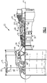
- FIG. 1 schematically illustrates a gas turbine engine 20.
- the gas turbine engine 20 is disclosed herein as a two-spool turbofan that generally incorporates a fan section 22, a compressor section 24, a combustor section 26 and a turbine section 28.
- the fan section 22 drives air along a bypass flow path B in a bypass duct defined within a housing 15 such as a fan case or nacelle, and also drives air along a core flow path C for compression and communication into the combustor section 26 then expansion through the turbine section 28.
- the exemplary engine 20 generally includes a low speed spool 30 and a high speed spool 32 mounted for rotation about an engine central longitudinal axis A relative to an engine static structure 36 via several bearing systems 38. It should be understood that various bearing systems 38 at various locations may alternatively or additionally be provided, and the location of bearing systems 38 may be varied as appropriate to the application.
- the low speed spool 30 generally includes an inner shaft 40 that interconnects, a first (or low) pressure compressor 44 and a first (or low) pressure turbine 46.
- the inner shaft 40 is connected to the fan 42 through a speed change mechanism, which in exemplary gas turbine engine 20 is illustrated as a geared architecture 48 to drive a fan 42 at a lower speed than the low speed spool 30.
- the high speed spool 32 includes an outer shaft 50 that interconnects a second (or high) pressure compressor 52 and a second (or high) pressure turbine 54.
- a combustor 56 is arranged in exemplary gas turbine 20 between the high pressure compressor 52 and the high pressure turbine 54.
- a mid-turbine frame 57 of the engine static structure 36 may be arranged generally between the high pressure turbine 54 and the low pressure turbine 46.
- the mid-turbine frame 57 further supports bearing systems 38 in the turbine section 28.
- the inner shaft 40 and the outer shaft 50 are concentric and rotate via bearing systems 38 about the engine central longitudinal axis A which is colline
- the core airflow is compressed by the low pressure compressor 44 then the high pressure compressor 52, mixed and burned with fuel in the combustor 56, then expanded over the high pressure turbine 54 and low pressure turbine 46.
- the mid-turbine frame 57 includes airfoils 59 which are in the core airflow path C.
- the turbines 46, 54 rotationally drive the respective low speed spool 30 and high speed spool 32 in response to the expansion.
- gear system 48 may be located aft of the low pressure compressor, or aft of the combustor section 26 or even aft of turbine section 28, and fan 42 may be positioned forward or aft of the location of gear system 48.
- the engine 20 in one example is a high-bypass geared aircraft engine.
- the engine 20 bypass ratio is greater than about six (6), with an example embodiment being greater than about ten (10)
- the geared architecture 48 is an epicyclic gear train, such as a planetary gear system or other gear system, with a gear reduction ratio of greater than about 2.3
- the low pressure turbine 46 has a pressure ratio that is greater than about five.
- the engine 20 bypass ratio is greater than about ten (10:1)
- the fan diameter is significantly larger than that of the low pressure compressor 44
- the low pressure turbine 46 has a pressure ratio that is greater than about five 5:1.
- Low pressure turbine 46 pressure ratio is pressure measured prior to inlet of low pressure turbine 46 as related to the pressure at the outlet of the low pressure turbine 46 prior to an exhaust nozzle.
- the geared architecture 48 may be an epicycle gear train, such as a planetary gear system or other gear system, with a gear reduction ratio of greater than about 2.3:1 and less than about 5:1. It should be understood, however, that the above parameters are only exemplary of one embodiment of a geared architecture engine and that the present invention is applicable to other gas turbine engines including direct drive turbofans.
- the fan section 22 of the engine 20 is designed for a particular flight condition -- typically cruise at about 0.8 Mach and about 35,000 feet (10,668 meters).
- the flight condition of 0.8 Mach and 35,000 ft (10,668 meters), with the engine at its best fuel consumption - also known as "bucket cruise Thrust Specific Fuel Consumption ('TSFC')" - is the industry standard parameter of lbm of fuel being burned divided by lbf of thrust the engine produces at that minimum point.
- "Low fan pressure ratio” is the pressure ratio across the fan blade alone, without a Fan Exit Guide Vane (“FEGV”) system.
- the low fan pressure ratio as disclosed herein according to one non-limiting embodiment is less than about 1.45.
- the "Low corrected fan tip speed” as disclosed herein according to one non-limiting embodiment is less than about 1150 ft / second (350.5 meters/second).
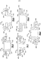
- FIG 2 shows a portion of an example turbine section 28, which may be incorporated into a gas turbine engine such as the one shown in Figure 1 .
- the turbine section 28 includes a plurality of alternating turbine blades 102 and turbine vanes 97.
- a turbine blade 102 has a radially outer tip 103 that is spaced from a blade outer air seal assembly 104 with a blade outer air seal ("BOAS") 106.
- the BOAS 106 may be mounted to an engine case or structure, such as engine static structure 36 via a control ring or support structure 110 and a carrier 112.
- the engine structure 36 may extend for a full 360° about the engine axis A.
- the turbine vane assembly 97 generally comprises a plurality of vane segments 118.
- each of the vane segments 118 has an airfoil 116 extending between an inner vane platform 120 and an outer vane platform 122.
- FIG. 3 illustrates an example vane segment 118.
- the vane segment 118 has an outer platform 122 radially outward of the airfoil 116 and an inner platform 120 radially inward of the airfoil 116.
- Each platform 122 has radially inner and outer sides R1, R2, respectively, first and second axial sides A1, A2, respectively, and first and second circumferential sides C1, C2, respectively.
- the radially inner side R1 faces in a direction toward the engine central axis A.
- the radially inner side R1 is thus the gas path side of the outer vane platform 122 that bounds a portion of the core flow path C.
- the first axial side A1 faces in a forward direction toward the front of the engine 20 (i.e., toward the fan 42), and the second axial side A2 faces in an aft direction toward the rear of the engine 20 (i.e., toward the exhaust end).
- the first axial side A1 is near the airfoil leading end (or leading edge) 124 and the second axial side A2 is near the airfoil trailing end (or trailing edge) 126.
- the first and second circumferential sides C1, C2 of each platform 122 abut circumferential sides C1, C2 of adjacent platforms 122.
- a vane platform 122 may apply to other components, and particularly flow path components.
- this disclosure may apply to combustor liner panels, shrouds, transition ducts, exhaust nozzle liners, blade outer air seals, or other CMC components.
- the example vane segment 118 is a singlet, meaning the vane segment 118 includes only one airfoil section 116. This disclosure is not limited to singlets, it may be doublets, triplets etc., however. Further, while the example vane segment 118 is in the high pressure turbine section 54, one would understand that this disclosure can be used in other sections of the engine 20 such as the mid-turbine frame 57. Further, although the outer vane platform 122 is generally shown and referenced, this disclosure may apply to the inner vane platform 120.
- Figure 4 illustrates a cross-sectional view of the vane segment 118 along the line 4-4 of Figure 3 .
- the segment 118 generally includes an outer portion 130 and a support structure 132.
- the support structure 132 has a radially extending portion 134 and an axially extending portion 136.
- the support structure 132 provides structural support for the vane 118.
- the radially extending portion 134 and the axially extending portion 136 may be formed as a single unitary component, for example.
- the support structure 132 may be formed from a metallic material.
- the outer portion 130 forms the airfoil 116 and inner and outer platforms 120, 122.
- the outer portion 130 is arranged within the core flowpath C. That is, the outer portion 130 is a portion of the segment 118 that is exposed to the core flowpath C.
- the outer portion 130 may be formed of a ceramic matrix composite ("CMC") material.
- the outer portion 130 may formed of a plurality of CMC laminate sheets.
- the laminate sheets may be silicon carbide fibers, formed into a braided or woven fabric in each layer. In other examples, the outer portion 130 may be made of a monolithic ceramic.
- CMC components such as outer portion 130 are formed by laying fiber material, such as laminate sheets or braids, in tooling, injecting a gaseous infiltrant into the tooling, and reacting to form a solid composite component.
- the component may be further processed by adding additional material to coat the laminate sheets.
- CMC components may have higher operating temperatures than components formed from other materials.
- the outer portion 130 may be spaced from the support structure 132 to form a gap 144 between the outer portion 130 and the support structure 132.
- the gap 144 may be used for directing cooling flow, for example.
- cooling flow F flows through the axially extending portion 136 of the support 132 to cool the vane assembly 118.
- a first seal 150 and a second seal 152 are arranged between the outer portion 130 and the support structure 132.
- the first seal 150 is arranged near the leading edge 124 and the second seal 152 is arranged near the trailing edge 126.
- the seals 150, 152 may be L-seals, for example.
- the first seal 150 prevents hot gases from the core flowpath C from entering the gap 144
- the second seal 152 prevents cooling flow F from leaking from the vane assembly 118.
- the outer platform 122 of the outer portion 130 has a first flange 160 and a second flange 162.
- the first and second flanges 160, 162 extend radially into the gap 144 between the outer portion 130 and the support structure 132.
- the first and second flanges 160, 162 extend radially outward from the outer portion 130 towards the axially extending portion 136 of the support structure 132.
- a clearance 166 in the axial direction is formed between the flanges 160, 162 and the axially extending portion 136.
- the clearance 166 may be between about 0.005 and about 0.020 inches (0.127 to 0.508 mm), for example.
- the flanges 160, 162 partially block the gap 144 and help prevent cooling flow leakage and/or hot gas ingestion by creating a torturous path between the support structure 132 and the outer portion 130. Although a particular arrangement with flanges 160, 162 is shown, the flanges may have a different arrangement, as shown and described below.
- Figure 5 illustrates another arrangement for an example vane assembly 218.
- the flanges 270, 272 terminate radially inward of the axial portion 236 of the support structure 232.
- the outer portion 230 includes flanges 270, 272 that are axially inward of the seals 250, 252 relative to the radial portion 234 of the support structure 232.
- the flange 270 near the leading edge 224 is aft of the seal 250 and the flange 272 is forward of the seal 252.
- the clearance 268 may be between about 0.005 and about 0.070 inches (0.127 to 1.78 mm), for example. That is, in this example, the flanges 270, 272 do not contact the axial portion 236 of the support structure 232. The flanges 270, 272 do not provide structural support to the assembly in this example. In this example, the flanges 270, 272 form a labyrinth flow discourager, and obstruct cooling air from leaking by introducing flow turning with edges and corners of the flanges 270, 272.
- Figure 6 illustrates another arrangement for an example vane assembly 318.
- the flanges 360, 362 wrap around the axial portion 336 of the support structure 332. That is, the flanges 360 extend radially outward of the axial portion 336.
- the first flange 360 extends axially forward of the axial portion 366, then curves to face axially aft.
- the second flange 362 extends axially aft of the axial portion 366, then curves to face axially forward.
- the flanges 360, 362 may be integrally formed as part of a CMC preform, or may be formed via machining.
- the flanges 360, 362 may reduce cooling flow leakage by creating a longer and more tortuous flow path for cooling flow leakage.
- Figure 7 illustrates another arrangement for an example vane assembly 418.
- multiple flanges may be used near the leading and/or trailing edges 424,426.
- the leading edge 424 includes a forward flange 460 that extends radially beyond the axial portion 436 and a forward flange 470 that terminates radially inward of the axial portion 436.
- the trailing edge 426 includes an aft flange 462 that extends radially beyond the axial portion 436 and an aft flange 472 that terminates radially inward of the axial portion 436.
- the flanges 480, 482 may extend from the axially extending portion 436 of the support structure 432.
- the flanges 480, 482 may be a metallic material and formed integrally with the support structure 432, for example. This arrangement functions as a labyrinth seal by creating a tortuous flow path for cooling flow leakage.
- Figures 8 illustrates another arrangement for an example vane assembly 518.
- the outer portion 530 has a flange 560 near the leading edge 524, and a different flange 572 near the trailing edge 526.
- the leading and trailing edges 524, 526 may have differing sealing needs, and thus different seal and flange arrangements.
- the seal 550 near the leading edge 524 may protect primarily against core flow path ingestion, while the seal 552 near the trailing edge 526 may protect primarily against cooling flow leakage.
- the flange 560 creates a tortuous path for hot gases from the core flow path.
- the flange 572 creates sharp edges to slow cooling flow leakage.
- Figure 9 illustrates a portion of an inner vane platform 620.
- the outer portion 630 has a forward flange 688 and an aft flange 690.
- the flanges 688, 690 extend axially forward and aft, respectively, of a radial portion 634 of the support structure 632.
- the flanges 684, 686, 688, 690 provide redundant protection to prevent such thermal gradients in the event a seal fails.
- the disclosed flange arrangements provide redundant protection against cooling flow leakage or hot gas ingestion.
- the outer portion 132 may be formed from a ceramic material, which has much higher temperature capabilities than the metallic support structure 132.
- cooling flow leakage and/or hot gas ingestion may create unwanted thermal gradients or prematurely wear components.
- the flanges may help to prevent leakage of cooling air or ingestion of hot gases into the gap 144 between the support structure 132 and the outer portion 130 in the event the seals fail.
- the flanges form a labyrinth flow discourager by obstructing the cooling air from leaking out by turning the flow and introducing sharp edges and corners. These sharp edges and corners slow the flow of leakage, reducing the amount of cooling air that is leaked through the gap.
- generally axially means a direction having a vector component in the axial direction that is greater than a vector component in the circumferential direction
- generally radially means a direction having a vector component in the radial direction that is greater than a vector component in the axial direction
- generally circumferentially means a direction having a vector component in the circumferential direction that is greater than a vector component in the axial direction.
Landscapes
- Engineering & Computer Science (AREA)
- Mechanical Engineering (AREA)
- General Engineering & Computer Science (AREA)
- Chemical & Material Sciences (AREA)
- Architecture (AREA)
- Ceramic Engineering (AREA)
- Materials Engineering (AREA)
- Turbine Rotor Nozzle Sealing (AREA)
Abstract
Description
- A gas turbine engine typically includes a fan section, a compressor section, a combustor section, and a turbine section. Air entering the compressor section is compressed and delivered into the combustion section where it is mixed with fuel and ignited to generate a high-speed exhaust gas flow. The high-speed exhaust gas flow expands through the turbine section to drive the compressor and the fan section.
- The compressor or turbine sections may include vanes mounted on vane platforms. Seals may be arranged at leading and trailing edges of such components to reduce cooling flow leakage.
- In one aspect, there is provided a flow path component assembly that includes a support structure that is a unitary component having an axial portion and a radial portion and an outer portion arranged between the support structure and a flow path. The outer portion defines a gap between the outer portion and the support structure axial portion. A flange extends into the gap.
- In an embodiment according to the above, the flange extends from the outer portion towards the support structure.
- In another embodiment according to any of the above, the flange extends from the support structure axial portion towards the outer portion.
- In another embodiment according to any of the above, a seal is arranged in the gap.
- In another embodiment according to any of the above, the flange is arranged between the seal and the radial portion.
- In another embodiment according to any of the above, the seal is arranged between the flange and the radial portion.
- In another embodiment according to any of the above, the flange is formed in the outer portion and a second flange is formed in the support structure.
- In another embodiment according to any of the above, the flange is near a leading edge.
- In another embodiment according to any of the above, the flange is near a trailing edge.
- In another embodiment according to any of the above, the platform is a vane platform.
- In another embodiment according to any of the above, the support structure extends between an inner vane platform and an outer vane platform.
- In another embodiment according to any of the above, the outer portion is formed from a ceramic material.
- In another embodiment according to any of the above, the support structure is formed from a metallic material.
- In another aspect, there is provided a turbine section for a gas turbine engine that includes a plurality of vanes arranged circumferentially about an engine axis. Each vane includes a support structure that is a unitary component having an axial portion and a radial portion, and an outer portion arranged between the support structure and a flow path. The outer portion is formed from a ceramic material. The outer portion defines a gap between the outer portion and the support structure axial portion. A flange extending radially from one of the axial portion and the outer portion. The flange is configured to at least partially block the gap.
- In an embodiment according to the above, a seal is arranged in the gap.
- In another embodiment according to any of the above, the flange extends from the outer portion towards the support structure.
- In another embodiment according to any of the above, the flange extends from the support structure towards the outer portion.
- In another embodiment according to any of the above, the outer portion has an outer axial portion that forms an outer platform of the vane.
- In another embodiment according to any of the above, the flange is arranged near a leading edge and extends forward of the axial portion and a second flange is arranged near a trailing edge and is forward of an aft end of the axial portion.
- In another embodiment according to any of the above, the flange is formed in the outer portion and a second flange is formed in the support structure.
- The present disclosure may include any one or more of the individual features disclosed above and/or below alone or in any combination thereof.
-
-
Figure 1 schematically illustrates an example gas turbine engine. -
Figure 2 schematically illustrates a portion of an example turbine section. -
Figure 3 schematically illustrates an example turbine vane assembly. -
Figure 4 schematically illustrates a cross-sectional view of an example turbine vane assembly. -
Figure 5 schematically illustrates another arrangement for an example vane assembly. -
Figure 6 schematically illustrates another arrangement for an example vane assembly. -
Figure 7 schematically illustrates another arrangement for an example vane assembly. -
Figure 8 schematically illustrates another arrangement for an example vane assembly. -
Figure 9 schematically illustrates another arrangement for an example vane assembly. -
Figure 1 schematically illustrates agas turbine engine 20. Thegas turbine engine 20 is disclosed herein as a two-spool turbofan that generally incorporates afan section 22, acompressor section 24, a combustor section 26 and aturbine section 28. Thefan section 22 drives air along a bypass flow path B in a bypass duct defined within ahousing 15 such as a fan case or nacelle, and also drives air along a core flow path C for compression and communication into the combustor section 26 then expansion through theturbine section 28. Although depicted as a two-spool turbofan gas turbine engine in the disclosed non-limiting embodiment, it should be understood that the concepts described herein are not limited to use with two-spool turbofans as the teachings may be applied to other types of turbine engines including three-spool architectures. - The
exemplary engine 20 generally includes alow speed spool 30 and ahigh speed spool 32 mounted for rotation about an engine central longitudinal axis A relative to an enginestatic structure 36 viaseveral bearing systems 38. It should be understood thatvarious bearing systems 38 at various locations may alternatively or additionally be provided, and the location ofbearing systems 38 may be varied as appropriate to the application. - The
low speed spool 30 generally includes aninner shaft 40 that interconnects, a first (or low) pressure compressor 44 and a first (or low)pressure turbine 46. Theinner shaft 40 is connected to thefan 42 through a speed change mechanism, which in exemplarygas turbine engine 20 is illustrated as a gearedarchitecture 48 to drive afan 42 at a lower speed than thelow speed spool 30. Thehigh speed spool 32 includes anouter shaft 50 that interconnects a second (or high)pressure compressor 52 and a second (or high)pressure turbine 54. Acombustor 56 is arranged inexemplary gas turbine 20 between thehigh pressure compressor 52 and thehigh pressure turbine 54. Amid-turbine frame 57 of the enginestatic structure 36 may be arranged generally between thehigh pressure turbine 54 and thelow pressure turbine 46. Themid-turbine frame 57 further supports bearingsystems 38 in theturbine section 28. Theinner shaft 40 and theouter shaft 50 are concentric and rotate viabearing systems 38 about the engine central longitudinal axis A which is collinear with their longitudinal axes. - The core airflow is compressed by the low pressure compressor 44 then the
high pressure compressor 52, mixed and burned with fuel in thecombustor 56, then expanded over thehigh pressure turbine 54 andlow pressure turbine 46. Themid-turbine frame 57 includesairfoils 59 which are in the core airflow path C. Theturbines low speed spool 30 andhigh speed spool 32 in response to the expansion. It will be appreciated that each of the positions of thefan section 22,compressor section 24, combustor section 26,turbine section 28, and fandrive gear system 48 may be varied. For example,gear system 48 may be located aft of the low pressure compressor, or aft of the combustor section 26 or even aft ofturbine section 28, andfan 42 may be positioned forward or aft of the location ofgear system 48. - The
engine 20 in one example is a high-bypass geared aircraft engine. In a further example, theengine 20 bypass ratio is greater than about six (6), with an example embodiment being greater than about ten (10), the gearedarchitecture 48 is an epicyclic gear train, such as a planetary gear system or other gear system, with a gear reduction ratio of greater than about 2.3 and thelow pressure turbine 46 has a pressure ratio that is greater than about five. In one disclosed embodiment, theengine 20 bypass ratio is greater than about ten (10:1), the fan diameter is significantly larger than that of the low pressure compressor 44, and thelow pressure turbine 46 has a pressure ratio that is greater than about five 5:1.Low pressure turbine 46 pressure ratio is pressure measured prior to inlet oflow pressure turbine 46 as related to the pressure at the outlet of thelow pressure turbine 46 prior to an exhaust nozzle. The gearedarchitecture 48 may be an epicycle gear train, such as a planetary gear system or other gear system, with a gear reduction ratio of greater than about 2.3:1 and less than about 5:1. It should be understood, however, that the above parameters are only exemplary of one embodiment of a geared architecture engine and that the present invention is applicable to other gas turbine engines including direct drive turbofans. - A significant amount of thrust is provided by the bypass flow B due to the high bypass ratio. The
fan section 22 of theengine 20 is designed for a particular flight condition -- typically cruise at about 0.8 Mach and about 35,000 feet (10,668 meters). The flight condition of 0.8 Mach and 35,000 ft (10,668 meters), with the engine at its best fuel consumption - also known as "bucket cruise Thrust Specific Fuel Consumption ('TSFC')" - is the industry standard parameter of lbm of fuel being burned divided by lbf of thrust the engine produces at that minimum point. "Low fan pressure ratio" is the pressure ratio across the fan blade alone, without a Fan Exit Guide Vane ("FEGV") system. The low fan pressure ratio as disclosed herein according to one non-limiting embodiment is less than about 1.45. "Low corrected fan tip speed" is the actual fan tip speed in ft/sec divided by an industry standard temperature correction of [(Tram °R) / (518.7 °R)]0.5 (where °R = K x 9/5). The "Low corrected fan tip speed" as disclosed herein according to one non-limiting embodiment is less than about 1150 ft / second (350.5 meters/second). -
Figure 2 shows a portion of anexample turbine section 28, which may be incorporated into a gas turbine engine such as the one shown inFigure 1 . However, it should be understood that other sections of thegas turbine engine 20 or other gas turbine engines, and even gas turbine engines not having a fan section at all, could benefit from this disclosure. Theturbine section 28 includes a plurality of alternatingturbine blades 102 andturbine vanes 97. - A
turbine blade 102 has a radiallyouter tip 103 that is spaced from a blade outerair seal assembly 104 with a blade outer air seal ("BOAS") 106. TheBOAS 106 may be mounted to an engine case or structure, such as enginestatic structure 36 via a control ring orsupport structure 110 and acarrier 112. Theengine structure 36 may extend for a full 360° about the engine axis A. - The
turbine vane assembly 97 generally comprises a plurality ofvane segments 118. In this example, each of thevane segments 118 has anairfoil 116 extending between aninner vane platform 120 and anouter vane platform 122. -
Figure 3 illustrates anexample vane segment 118. Thevane segment 118 has anouter platform 122 radially outward of theairfoil 116 and aninner platform 120 radially inward of theairfoil 116. Eachplatform 122 has radially inner and outer sides R1, R2, respectively, first and second axial sides A1, A2, respectively, and first and second circumferential sides C1, C2, respectively. The radially inner side R1 faces in a direction toward the engine central axis A. The radially inner side R1 is thus the gas path side of theouter vane platform 122 that bounds a portion of the core flow path C. The first axial side A1 faces in a forward direction toward the front of the engine 20 (i.e., toward the fan 42), and the second axial side A2 faces in an aft direction toward the rear of the engine 20 (i.e., toward the exhaust end). In other words, the first axial side A1 is near the airfoil leading end (or leading edge) 124 and the second axial side A2 is near the airfoil trailing end (or trailing edge) 126. The first and second circumferential sides C1, C2 of eachplatform 122 abut circumferential sides C1, C2 ofadjacent platforms 122. - Although a
vane platform 122 is described, this disclosure may apply to other components, and particularly flow path components. For example, this disclosure may apply to combustor liner panels, shrouds, transition ducts, exhaust nozzle liners, blade outer air seals, or other CMC components. In the illustrated example, theexample vane segment 118 is a singlet, meaning thevane segment 118 includes only oneairfoil section 116. This disclosure is not limited to singlets, it may be doublets, triplets etc., however. Further, while theexample vane segment 118 is in the highpressure turbine section 54, one would understand that this disclosure can be used in other sections of theengine 20 such as themid-turbine frame 57. Further, although theouter vane platform 122 is generally shown and referenced, this disclosure may apply to theinner vane platform 120. -
Figure 4 illustrates a cross-sectional view of thevane segment 118 along the line 4-4 ofFigure 3 . Thesegment 118 generally includes anouter portion 130 and asupport structure 132. Thesupport structure 132 has a radially extending portion 134 and anaxially extending portion 136. Thesupport structure 132 provides structural support for thevane 118. The radially extending portion 134 and theaxially extending portion 136 may be formed as a single unitary component, for example. Thesupport structure 132 may be formed from a metallic material. - The
outer portion 130 forms theairfoil 116 and inner andouter platforms outer portion 130 is arranged within the core flowpath C. That is, theouter portion 130 is a portion of thesegment 118 that is exposed to the core flowpath C. Theouter portion 130 may be formed of a ceramic matrix composite ("CMC") material. Theouter portion 130 may formed of a plurality of CMC laminate sheets. The laminate sheets may be silicon carbide fibers, formed into a braided or woven fabric in each layer. In other examples, theouter portion 130 may be made of a monolithic ceramic. CMC components such asouter portion 130 are formed by laying fiber material, such as laminate sheets or braids, in tooling, injecting a gaseous infiltrant into the tooling, and reacting to form a solid composite component. The component may be further processed by adding additional material to coat the laminate sheets. CMC components may have higher operating temperatures than components formed from other materials. - The
outer portion 130 may be spaced from thesupport structure 132 to form agap 144 between theouter portion 130 and thesupport structure 132. Thegap 144 may be used for directing cooling flow, for example. In the illustrated example, cooling flow F flows through theaxially extending portion 136 of thesupport 132 to cool thevane assembly 118. In this example, afirst seal 150 and asecond seal 152 are arranged between theouter portion 130 and thesupport structure 132. Thefirst seal 150 is arranged near theleading edge 124 and thesecond seal 152 is arranged near the trailingedge 126. Theseals first seal 150 prevents hot gases from the core flowpath C from entering thegap 144, and thesecond seal 152 prevents cooling flow F from leaking from thevane assembly 118. - The
outer platform 122 of theouter portion 130 has afirst flange 160 and asecond flange 162. The first andsecond flanges gap 144 between theouter portion 130 and thesupport structure 132. In this example, the first andsecond flanges outer portion 130 towards theaxially extending portion 136 of thesupport structure 132. A clearance 166 in the axial direction is formed between theflanges axially extending portion 136. The clearance 166 may be between about 0.005 and about 0.020 inches (0.127 to 0.508 mm), for example. Theflanges gap 144 and help prevent cooling flow leakage and/or hot gas ingestion by creating a torturous path between thesupport structure 132 and theouter portion 130. Although a particular arrangement withflanges -
Figure 5 illustrates another arrangement for anexample vane assembly 218. In this example, theflanges axial portion 236 of thesupport structure 232. In this example, theouter portion 230 includesflanges seals support structure 232. In other words, theflange 270 near theleading edge 224 is aft of theseal 250 and theflange 272 is forward of theseal 252. In this example, there may be aclearance 268 in the radial direction between theflange 270 and theaxial portion 236 of thesupport structure 232. In one example, theclearance 268 may be between about 0.005 and about 0.070 inches (0.127 to 1.78 mm), for example. That is, in this example, theflanges axial portion 236 of thesupport structure 232. Theflanges flanges flanges -
Figure 6 illustrates another arrangement for anexample vane assembly 318. In this example, theflanges axial portion 336 of thesupport structure 332. That is, theflanges 360 extend radially outward of theaxial portion 336. Thefirst flange 360 extends axially forward of the axial portion 366, then curves to face axially aft. Thesecond flange 362 extends axially aft of the axial portion 366, then curves to face axially forward. Theflanges flanges -
Figure 7 illustrates another arrangement for anexample vane assembly 418. In this example, multiple flanges may be used near the leading and/or trailing edges 424,426. For example, theleading edge 424 includes aforward flange 460 that extends radially beyond theaxial portion 436 and aforward flange 470 that terminates radially inward of theaxial portion 436. The trailingedge 426 includes anaft flange 462 that extends radially beyond theaxial portion 436 and anaft flange 472 that terminates radially inward of theaxial portion 436. In this example, theflanges axially extending portion 436 of thesupport structure 432. Theflanges support structure 432, for example. This arrangement functions as a labyrinth seal by creating a tortuous flow path for cooling flow leakage. -
Figures 8 illustrates another arrangement for anexample vane assembly 518. In this example, theouter portion 530 has aflange 560 near theleading edge 524, and adifferent flange 572 near the trailingedge 526. The leading and trailingedges seal 550 near theleading edge 524 may protect primarily against core flow path ingestion, while theseal 552 near the trailingedge 526 may protect primarily against cooling flow leakage. In the event theseal 550 fails, theflange 560 creates a tortuous path for hot gases from the core flow path. In the event theseal 552 fails, theflange 572 creates sharp edges to slow cooling flow leakage. Although a particular flange combination is shown, other leading and trailing edge flange arrangements may be used. -
Figure 9 illustrates a portion of aninner vane platform 620. In this example, theouter portion 630 has aforward flange 688 and anaft flange 690. Theflanges radial portion 634 of thesupport structure 632. At theinner platform 620, if the seal fails, too much cooling flow across the vane may result in unwanted thermal gradients. Theflanges - The disclosed flange arrangements provide redundant protection against cooling flow leakage or hot gas ingestion. The
outer portion 132 may be formed from a ceramic material, which has much higher temperature capabilities than themetallic support structure 132. Thus, cooling flow leakage and/or hot gas ingestion may create unwanted thermal gradients or prematurely wear components. The flanges may help to prevent leakage of cooling air or ingestion of hot gases into thegap 144 between thesupport structure 132 and theouter portion 130 in the event the seals fail. The flanges form a labyrinth flow discourager by obstructing the cooling air from leaking out by turning the flow and introducing sharp edges and corners. These sharp edges and corners slow the flow of leakage, reducing the amount of cooling air that is leaked through the gap. - In this disclosure, "generally axially" means a direction having a vector component in the axial direction that is greater than a vector component in the circumferential direction, "generally radially" means a direction having a vector component in the radial direction that is greater than a vector component in the axial direction and "generally circumferentially" means a direction having a vector component in the circumferential direction that is greater than a vector component in the axial direction.
- Although a combination of features is shown in the illustrated examples, not all of them need to be combined to realize the benefits of various embodiments of this disclosure. In other words, a system designed according to an embodiment of this disclosure will not necessarily include all of the features shown in any one of the Figures or all of the portions schematically shown in the Figures. Moreover, selected features of one example embodiment may be combined with selected features of other example embodiments.
- Although an embodiment of this invention has been disclosed, a worker of ordinary skill in this art would recognize that certain modifications would come within the scope of this disclosure. For that reason, the following claims should be studied to determine the true scope and content of this disclosure.
Claims (15)
- A flow path component assembly (118), comprising:a support structure (132) that is a unitary component having an axial portion (136) and a radial portion (134);an outer portion (130) arranged between the support structure (132) and a flow path (C), wherein the outer portion (130) defines a gap (144) between the outer portion (130) and the support structure axial portion (136); anda flange (160; 162) extending into the gap (144).
- The flow path component assembly (118) of claim 1, wherein the flange (160; 162) extends from the outer portion (130) towards the support structure (132).
- The flow path component assembly (418; 618) of claim 1, wherein the flange (480; 482; 684; 686) extends from the support structure axial portion (436; 636) towards the outer portion (630).
- The flow path component assembly of any of claims 1 to 3, wherein a seal (150; 152) is arranged in the gap (144).
- The flow path component assembly (218; 418; 518; 618) of claim 4, wherein the flange (270; 272; 470; 472; 480; 482; 572; 684; 686) is arranged between the seal (250; 252; 552) and the radial portion (634).
- The flow path component assembly (118; 318; 418; 518; 618) of claim 4, wherein the seal (150; 152; 350; 352; 550) is arranged between the flange (160; 162; 360; 362; 460; 462; 560; 688; 690) and the radial portion (134; 634).
- The flow path component assembly (418; 518; 618) of any preceding claim, wherein the flange (460; 462; 560; 688; 690) is formed in the outer portion (530; 630) and a second flange (480; 482; 684; 686) is formed in the support structure (432; 532; 632).
- The flow path component assembly (118) of any preceding claim, wherein the flange (160) is near a leading edge (124).
- The flow path component assembly (118) of any of claims 1 to 7, wherein the flange (162) is near a trailing edge (126).
- The flow path component assembly (118) of any preceding claim, comprising a platform (120; 122), wherein the platform (120; 122) is a vane platform (120; 122), wherein the support structure (132) optionally extends between an inner vane platform (120) and an outer vane platform (122).
- The flow path component assembly (118) of any preceding claim, wherein the outer portion (130) is formed from a ceramic material and/or wherein the support structure (132) is formed from a metallic material.
- A turbine section (28) for a gas turbine engine (20), comprising:
a plurality of vanes (97) arranged circumferentially about an engine axis (A), each vane (97) comprising:a support structure (132) that is a unitary component having an axial portion (136) and a radial portion (134);an outer portion (130) arranged between the support structure (132) and a flow path (C), the outer portion (130) formed from a ceramic material, wherein the outer portion (130) defines a gap (144) between the outer portion (130) and the support structure axial portion (136); anda flange (160; 162) extending radially from one of the axial portion (136) and the outer portion (130), the flange (160; 162) configured to at least partially block the gap (144),wherein, optionally, a seal (150; 152) is arranged in the gap (144). - The turbine section (28) of claim 12, wherein the flange (160; 162) extends from the outer portion (130) towards the support structure (132) or wherein the flange (480; 482; 684; 686) extends from the support structure (432; 632) towards the outer portion (630).
- The turbine section (28) of claim 12 or 13, wherein the outer portion (130) has an outer axial portion that forms an outer platform (120; 122) of the vane (97).
- The turbine section (28) of any of claims 12 to 14, wherein the flange (560) is arranged near a leading edge (524) and extends forward of the axial portion (536) and a second flange (562) is arranged near a trailing edge (526) and is forward of an aft end of the axial portion (536); and/or wherein the flange (560) is formed in the outer portion (530) and a or the second flange (562) is formed in the support structure (532).
Applications Claiming Priority (1)
| Application Number | Priority Date | Filing Date | Title |
|---|---|---|---|
| US17/221,036 US11454129B1 (en) | 2021-04-02 | 2021-04-02 | CMC component flow discourager flanges |
Publications (2)
| Publication Number | Publication Date |
|---|---|
| EP4067622A1 true EP4067622A1 (en) | 2022-10-05 |
| EP4067622B1 EP4067622B1 (en) | 2025-04-30 |
Family
ID=81325689
Family Applications (1)
| Application Number | Title | Priority Date | Filing Date |
|---|---|---|---|
| EP22165971.7A Active EP4067622B1 (en) | 2021-04-02 | 2022-03-31 | Cmc component flow discourager flanges |
Country Status (2)
| Country | Link |
|---|---|
| US (2) | US11454129B1 (en) |
| EP (1) | EP4067622B1 (en) |
Families Citing this family (8)
| Publication number | Priority date | Publication date | Assignee | Title |
|---|---|---|---|---|
| US11047248B2 (en) * | 2018-06-19 | 2021-06-29 | General Electric Company | Curved seal for adjacent gas turbine components |
| US11708765B1 (en) * | 2022-05-13 | 2023-07-25 | Raytheon Technologies Corporation | Gas turbine engine article with branched flange |
| US11952917B2 (en) * | 2022-08-05 | 2024-04-09 | Rtx Corporation | Vane multiplet with conjoined singlet vanes |
| US12078083B2 (en) * | 2022-12-20 | 2024-09-03 | Rtx Corporation | Contour weaves for interwoven vanes |
| US12326099B2 (en) | 2023-08-21 | 2025-06-10 | Rtx Corporation | Bathtub seal integrated into CMC vane load path |
| US12281597B2 (en) | 2023-08-21 | 2025-04-22 | Rtx Corporation | CMC vane with rotatable baffle design to accommodate re-stagger |
| US12025029B1 (en) * | 2023-08-21 | 2024-07-02 | Rtx Corporation | Bathtub seal for damping CMC vane platform |
| US12503949B1 (en) | 2024-11-21 | 2025-12-23 | Rtx Corporation | Gapped attachment for ceramic matrix composite vane and method |
Citations (3)
| Publication number | Priority date | Publication date | Assignee | Title |
|---|---|---|---|---|
| US20080279679A1 (en) * | 2007-05-09 | 2008-11-13 | Siemens Power Generation, Inc. | Multivane segment mounting arrangement for a gas turbine |
| US20160084096A1 (en) * | 2014-09-24 | 2016-03-24 | United Technologies Corporation | Clamped vane arc segment having load-transmitting features |
| EP3597865A1 (en) * | 2018-07-17 | 2020-01-22 | Rolls-Royce Corporation | Turbine vane assembly with ceramic matrix composite components |
Family Cites Families (9)
| Publication number | Priority date | Publication date | Assignee | Title |
|---|---|---|---|---|
| US20100275572A1 (en) * | 2009-04-30 | 2010-11-04 | Pratt & Whitney Canada Corp. | Oil line insulation system for mid turbine frame |
| ES2728228T3 (en) * | 2011-04-15 | 2019-10-23 | MTU Aero Engines AG | Procedure for manufacturing a component with at least one construction element arranged in the component, as well as a component with at least one construction element |
| US9335051B2 (en) * | 2011-07-13 | 2016-05-10 | United Technologies Corporation | Ceramic matrix composite combustor vane ring assembly |
| EP2984292B1 (en) | 2013-04-12 | 2018-06-06 | United Technologies Corporation | Stator vane platform with flanges |
| US10830063B2 (en) * | 2018-07-20 | 2020-11-10 | Rolls-Royce North American Technologies Inc. | Turbine vane assembly with ceramic matrix composite components |
| US11454128B2 (en) * | 2018-08-06 | 2022-09-27 | General Electric Company | Fairing assembly |
| US10927689B2 (en) * | 2018-08-31 | 2021-02-23 | Rolls-Royce Corporation | Turbine vane assembly with ceramic matrix composite components mounted to case |
| US10767497B2 (en) | 2018-09-07 | 2020-09-08 | Rolls-Royce Corporation | Turbine vane assembly with ceramic matrix composite components |
| US10767495B2 (en) * | 2019-02-01 | 2020-09-08 | Rolls-Royce Plc | Turbine vane assembly with cooling feature |
-
2021
- 2021-04-02 US US17/221,036 patent/US11454129B1/en active Active
-
2022
- 2022-03-31 EP EP22165971.7A patent/EP4067622B1/en active Active
- 2022-09-26 US US17/952,693 patent/US11808154B2/en active Active
Patent Citations (3)
| Publication number | Priority date | Publication date | Assignee | Title |
|---|---|---|---|---|
| US20080279679A1 (en) * | 2007-05-09 | 2008-11-13 | Siemens Power Generation, Inc. | Multivane segment mounting arrangement for a gas turbine |
| US20160084096A1 (en) * | 2014-09-24 | 2016-03-24 | United Technologies Corporation | Clamped vane arc segment having load-transmitting features |
| EP3597865A1 (en) * | 2018-07-17 | 2020-01-22 | Rolls-Royce Corporation | Turbine vane assembly with ceramic matrix composite components |
Also Published As
| Publication number | Publication date |
|---|---|
| US20220316353A1 (en) | 2022-10-06 |
| US20230036836A1 (en) | 2023-02-02 |
| EP4067622B1 (en) | 2025-04-30 |
| US11454129B1 (en) | 2022-09-27 |
| US11808154B2 (en) | 2023-11-07 |
Similar Documents
| Publication | Publication Date | Title |
|---|---|---|
| EP3819475B1 (en) | Blade outer air seal arrangement and method of sealing | |
| EP3816406B1 (en) | Cmc heat shield for a gas turbine | |
| EP4067622B1 (en) | Cmc component flow discourager flanges | |
| EP4056811A1 (en) | Scalloped mateface seal arrangement for cmc platforms | |
| US11105215B2 (en) | Feather seal slot arrangement for a CMC BOAS assembly | |
| US11624292B2 (en) | Feather seal for CMC BOAS | |
| US11326463B2 (en) | BOAS thermal baffle | |
| EP3219933B1 (en) | Seal assembly, gas turbine having the same, and method of assembling a seal assembly | |
| US11512604B1 (en) | Spring for radially stacked assemblies | |
| EP3219930A1 (en) | Blade outer air seal with a heat shield | |
| US20210148247A1 (en) | Blade outer air seal including cooling trench | |
| EP4086435B1 (en) | Variable thickness machinable coating for platform seals | |
| EP4086434A2 (en) | Cmc vane with platform cover | |
| EP4086433A1 (en) | Seal assembly with seal arc segment | |
| EP3620611B1 (en) | Unified boas support and vane platform | |
| US11073036B2 (en) | Boas flow directing arrangement | |
| EP4056812A1 (en) | Chevron grooved mateface seal | |
| EP3760836A1 (en) | Double box boas and carrier system | |
| EP3819476B1 (en) | Boas assembly for a gas turbine |
Legal Events
| Date | Code | Title | Description |
|---|---|---|---|
| PUAI | Public reference made under article 153(3) epc to a published international application that has entered the european phase |
Free format text: ORIGINAL CODE: 0009012 |
|
| STAA | Information on the status of an ep patent application or granted ep patent |
Free format text: STATUS: THE APPLICATION HAS BEEN PUBLISHED |
|
| AK | Designated contracting states |
Kind code of ref document: A1 Designated state(s): AL AT BE BG CH CY CZ DE DK EE ES FI FR GB GR HR HU IE IS IT LI LT LU LV MC MK MT NL NO PL PT RO RS SE SI SK SM TR |
|
| STAA | Information on the status of an ep patent application or granted ep patent |
Free format text: STATUS: REQUEST FOR EXAMINATION WAS MADE |
|
| 17P | Request for examination filed |
Effective date: 20230331 |
|
| RBV | Designated contracting states (corrected) |
Designated state(s): AL AT BE BG CH CY CZ DE DK EE ES FI FR GB GR HR HU IE IS IT LI LT LU LV MC MK MT NL NO PL PT RO RS SE SI SK SM TR |
|
| RAP3 | Party data changed (applicant data changed or rights of an application transferred) |
Owner name: RTX CORPORATION |
|
| STAA | Information on the status of an ep patent application or granted ep patent |
Free format text: STATUS: EXAMINATION IS IN PROGRESS |
|
| 17Q | First examination report despatched |
Effective date: 20240104 |
|
| GRAP | Despatch of communication of intention to grant a patent |
Free format text: ORIGINAL CODE: EPIDOSNIGR1 |
|
| STAA | Information on the status of an ep patent application or granted ep patent |
Free format text: STATUS: GRANT OF PATENT IS INTENDED |
|
| INTG | Intention to grant announced |
Effective date: 20241206 |
|
| GRAS | Grant fee paid |
Free format text: ORIGINAL CODE: EPIDOSNIGR3 |
|
| GRAA | (expected) grant |
Free format text: ORIGINAL CODE: 0009210 |
|
| STAA | Information on the status of an ep patent application or granted ep patent |
Free format text: STATUS: THE PATENT HAS BEEN GRANTED |
|
| AK | Designated contracting states |
Kind code of ref document: B1 Designated state(s): AL AT BE BG CH CY CZ DE DK EE ES FI FR GB GR HR HU IE IS IT LI LT LU LV MC MK MT NL NO PL PT RO RS SE SI SK SM TR |
|
| REG | Reference to a national code |
Ref country code: CH Ref legal event code: EP Ref country code: GB Ref legal event code: FG4D |
|
| REG | Reference to a national code |
Ref country code: DE Ref legal event code: R096 Ref document number: 602022013765 Country of ref document: DE |
|
| REG | Reference to a national code |
Ref country code: IE Ref legal event code: FG4D |
|
| REG | Reference to a national code |
Ref country code: NL Ref legal event code: MP Effective date: 20250430 |
|
| REG | Reference to a national code |
Ref country code: AT Ref legal event code: MK05 Ref document number: 1790190 Country of ref document: AT Kind code of ref document: T Effective date: 20250430 |
|
| PG25 | Lapsed in a contracting state [announced via postgrant information from national office to epo] |
Ref country code: FI Free format text: LAPSE BECAUSE OF FAILURE TO SUBMIT A TRANSLATION OF THE DESCRIPTION OR TO PAY THE FEE WITHIN THE PRESCRIBED TIME-LIMIT Effective date: 20250430 Ref country code: PT Free format text: LAPSE BECAUSE OF FAILURE TO SUBMIT A TRANSLATION OF THE DESCRIPTION OR TO PAY THE FEE WITHIN THE PRESCRIBED TIME-LIMIT Effective date: 20250901 Ref country code: ES Free format text: LAPSE BECAUSE OF FAILURE TO SUBMIT A TRANSLATION OF THE DESCRIPTION OR TO PAY THE FEE WITHIN THE PRESCRIBED TIME-LIMIT Effective date: 20250430 |
|
| REG | Reference to a national code |
Ref country code: LT Ref legal event code: MG9D |
|
| PG25 | Lapsed in a contracting state [announced via postgrant information from national office to epo] |
Ref country code: GR Free format text: LAPSE BECAUSE OF FAILURE TO SUBMIT A TRANSLATION OF THE DESCRIPTION OR TO PAY THE FEE WITHIN THE PRESCRIBED TIME-LIMIT Effective date: 20250731 Ref country code: NO Free format text: LAPSE BECAUSE OF FAILURE TO SUBMIT A TRANSLATION OF THE DESCRIPTION OR TO PAY THE FEE WITHIN THE PRESCRIBED TIME-LIMIT Effective date: 20250730 |
|
| PG25 | Lapsed in a contracting state [announced via postgrant information from national office to epo] |
Ref country code: PL Free format text: LAPSE BECAUSE OF FAILURE TO SUBMIT A TRANSLATION OF THE DESCRIPTION OR TO PAY THE FEE WITHIN THE PRESCRIBED TIME-LIMIT Effective date: 20250430 Ref country code: NL Free format text: LAPSE BECAUSE OF FAILURE TO SUBMIT A TRANSLATION OF THE DESCRIPTION OR TO PAY THE FEE WITHIN THE PRESCRIBED TIME-LIMIT Effective date: 20250430 |
|
| PG25 | Lapsed in a contracting state [announced via postgrant information from national office to epo] |
Ref country code: BG Free format text: LAPSE BECAUSE OF FAILURE TO SUBMIT A TRANSLATION OF THE DESCRIPTION OR TO PAY THE FEE WITHIN THE PRESCRIBED TIME-LIMIT Effective date: 20250430 |
|
| PG25 | Lapsed in a contracting state [announced via postgrant information from national office to epo] |
Ref country code: HR Free format text: LAPSE BECAUSE OF FAILURE TO SUBMIT A TRANSLATION OF THE DESCRIPTION OR TO PAY THE FEE WITHIN THE PRESCRIBED TIME-LIMIT Effective date: 20250430 |
|
| PG25 | Lapsed in a contracting state [announced via postgrant information from national office to epo] |
Ref country code: AT Free format text: LAPSE BECAUSE OF FAILURE TO SUBMIT A TRANSLATION OF THE DESCRIPTION OR TO PAY THE FEE WITHIN THE PRESCRIBED TIME-LIMIT Effective date: 20250430 |
|
| PG25 | Lapsed in a contracting state [announced via postgrant information from national office to epo] |
Ref country code: RS Free format text: LAPSE BECAUSE OF FAILURE TO SUBMIT A TRANSLATION OF THE DESCRIPTION OR TO PAY THE FEE WITHIN THE PRESCRIBED TIME-LIMIT Effective date: 20250731 |
|
| PG25 | Lapsed in a contracting state [announced via postgrant information from national office to epo] |
Ref country code: IS Free format text: LAPSE BECAUSE OF FAILURE TO SUBMIT A TRANSLATION OF THE DESCRIPTION OR TO PAY THE FEE WITHIN THE PRESCRIBED TIME-LIMIT Effective date: 20250830 |
|
| PG25 | Lapsed in a contracting state [announced via postgrant information from national office to epo] |
Ref country code: LV Free format text: LAPSE BECAUSE OF FAILURE TO SUBMIT A TRANSLATION OF THE DESCRIPTION OR TO PAY THE FEE WITHIN THE PRESCRIBED TIME-LIMIT Effective date: 20250430 |
|
| PG25 | Lapsed in a contracting state [announced via postgrant information from national office to epo] |
Ref country code: SM Free format text: LAPSE BECAUSE OF FAILURE TO SUBMIT A TRANSLATION OF THE DESCRIPTION OR TO PAY THE FEE WITHIN THE PRESCRIBED TIME-LIMIT Effective date: 20250430 Ref country code: DK Free format text: LAPSE BECAUSE OF FAILURE TO SUBMIT A TRANSLATION OF THE DESCRIPTION OR TO PAY THE FEE WITHIN THE PRESCRIBED TIME-LIMIT Effective date: 20250430 |
|
| PG25 | Lapsed in a contracting state [announced via postgrant information from national office to epo] |
Ref country code: CZ Free format text: LAPSE BECAUSE OF FAILURE TO SUBMIT A TRANSLATION OF THE DESCRIPTION OR TO PAY THE FEE WITHIN THE PRESCRIBED TIME-LIMIT Effective date: 20250430 |
|
| PG25 | Lapsed in a contracting state [announced via postgrant information from national office to epo] |
Ref country code: EE Free format text: LAPSE BECAUSE OF FAILURE TO SUBMIT A TRANSLATION OF THE DESCRIPTION OR TO PAY THE FEE WITHIN THE PRESCRIBED TIME-LIMIT Effective date: 20250430 |
|
| PG25 | Lapsed in a contracting state [announced via postgrant information from national office to epo] |
Ref country code: SK Free format text: LAPSE BECAUSE OF FAILURE TO SUBMIT A TRANSLATION OF THE DESCRIPTION OR TO PAY THE FEE WITHIN THE PRESCRIBED TIME-LIMIT Effective date: 20250430 |
|
| PG25 | Lapsed in a contracting state [announced via postgrant information from national office to epo] |
Ref country code: IT Free format text: LAPSE BECAUSE OF FAILURE TO SUBMIT A TRANSLATION OF THE DESCRIPTION OR TO PAY THE FEE WITHIN THE PRESCRIBED TIME-LIMIT Effective date: 20250430 |
|
| REG | Reference to a national code |
Ref country code: DE Ref legal event code: R097 Ref document number: 602022013765 Country of ref document: DE |
|
| PLBE | No opposition filed within time limit |
Free format text: ORIGINAL CODE: 0009261 |
|
| STAA | Information on the status of an ep patent application or granted ep patent |
Free format text: STATUS: NO OPPOSITION FILED WITHIN TIME LIMIT |
|
| REG | Reference to a national code |
Ref country code: CH Ref legal event code: L10 Free format text: ST27 STATUS EVENT CODE: U-0-0-L10-L00 (AS PROVIDED BY THE NATIONAL OFFICE) Effective date: 20260311 |
|
| 26N | No opposition filed |
Effective date: 20260202 |
|
| PGFP | Annual fee paid to national office [announced via postgrant information from national office to epo] |
Ref country code: GB Payment date: 20260220 Year of fee payment: 5 |
|
| PGFP | Annual fee paid to national office [announced via postgrant information from national office to epo] |
Ref country code: DE Payment date: 20260219 Year of fee payment: 5 |
|
| PGFP | Annual fee paid to national office [announced via postgrant information from national office to epo] |
Ref country code: FR Payment date: 20260220 Year of fee payment: 5 |