EP4086434A2 - Cmc vane with platform cover - Google Patents
Cmc vane with platform cover Download PDFInfo
- Publication number
- EP4086434A2 EP4086434A2 EP22170311.9A EP22170311A EP4086434A2 EP 4086434 A2 EP4086434 A2 EP 4086434A2 EP 22170311 A EP22170311 A EP 22170311A EP 4086434 A2 EP4086434 A2 EP 4086434A2
- Authority
- EP
- European Patent Office
- Prior art keywords
- vane
- platform
- cover
- flange
- engine
- Prior art date
- Legal status (The legal status is an assumption and is not a legal conclusion. Google has not performed a legal analysis and makes no representation as to the accuracy of the status listed.)
- Pending
Links
Images


Classifications
-
- F—MECHANICAL ENGINEERING; LIGHTING; HEATING; WEAPONS; BLASTING
- F01—MACHINES OR ENGINES IN GENERAL; ENGINE PLANTS IN GENERAL; STEAM ENGINES
- F01D—NON-POSITIVE DISPLACEMENT MACHINES OR ENGINES, e.g. STEAM TURBINES
- F01D9/00—Stators
- F01D9/02—Nozzles; Nozzle boxes; Stator blades; Guide conduits, e.g. individual nozzles
- F01D9/04—Nozzles; Nozzle boxes; Stator blades; Guide conduits, e.g. individual nozzles forming ring or sector
- F01D9/042—Nozzles; Nozzle boxes; Stator blades; Guide conduits, e.g. individual nozzles forming ring or sector fixing blades to stators
-
- F—MECHANICAL ENGINEERING; LIGHTING; HEATING; WEAPONS; BLASTING
- F01—MACHINES OR ENGINES IN GENERAL; ENGINE PLANTS IN GENERAL; STEAM ENGINES
- F01D—NON-POSITIVE DISPLACEMENT MACHINES OR ENGINES, e.g. STEAM TURBINES
- F01D25/00—Component parts, details, or accessories, not provided for in, or of interest apart from, other groups
- F01D25/24—Casings; Casing parts, e.g. diaphragms, casing fastenings
- F01D25/243—Flange connections; Bolting arrangements
-
- F—MECHANICAL ENGINEERING; LIGHTING; HEATING; WEAPONS; BLASTING
- F01—MACHINES OR ENGINES IN GENERAL; ENGINE PLANTS IN GENERAL; STEAM ENGINES
- F01D—NON-POSITIVE DISPLACEMENT MACHINES OR ENGINES, e.g. STEAM TURBINES
- F01D5/00—Blades; Blade-carrying members; Heating, heat-insulating, cooling or antivibration means on the blades or the members
- F01D5/12—Blades
- F01D5/14—Form or construction
- F01D5/147—Construction, i.e. structural features, e.g. of weight-saving hollow blades
-
- F—MECHANICAL ENGINEERING; LIGHTING; HEATING; WEAPONS; BLASTING
- F01—MACHINES OR ENGINES IN GENERAL; ENGINE PLANTS IN GENERAL; STEAM ENGINES
- F01D—NON-POSITIVE DISPLACEMENT MACHINES OR ENGINES, e.g. STEAM TURBINES
- F01D5/00—Blades; Blade-carrying members; Heating, heat-insulating, cooling or antivibration means on the blades or the members
- F01D5/12—Blades
- F01D5/14—Form or construction
- F01D5/18—Hollow blades, i.e. blades with cooling or heating channels or cavities; Heating, heat-insulating or cooling means on blades
- F01D5/187—Convection cooling
-
- F—MECHANICAL ENGINEERING; LIGHTING; HEATING; WEAPONS; BLASTING
- F01—MACHINES OR ENGINES IN GENERAL; ENGINE PLANTS IN GENERAL; STEAM ENGINES
- F01D—NON-POSITIVE DISPLACEMENT MACHINES OR ENGINES, e.g. STEAM TURBINES
- F01D5/00—Blades; Blade-carrying members; Heating, heat-insulating, cooling or antivibration means on the blades or the members
- F01D5/12—Blades
- F01D5/28—Selecting particular materials; Particular measures relating thereto; Measures against erosion or corrosion
- F01D5/284—Selection of ceramic materials
-
- F—MECHANICAL ENGINEERING; LIGHTING; HEATING; WEAPONS; BLASTING
- F01—MACHINES OR ENGINES IN GENERAL; ENGINE PLANTS IN GENERAL; STEAM ENGINES
- F01D—NON-POSITIVE DISPLACEMENT MACHINES OR ENGINES, e.g. STEAM TURBINES
- F01D9/00—Stators
- F01D9/02—Nozzles; Nozzle boxes; Stator blades; Guide conduits, e.g. individual nozzles
- F01D9/04—Nozzles; Nozzle boxes; Stator blades; Guide conduits, e.g. individual nozzles forming ring or sector
- F01D9/041—Nozzles; Nozzle boxes; Stator blades; Guide conduits, e.g. individual nozzles forming ring or sector using blades
-
- F—MECHANICAL ENGINEERING; LIGHTING; HEATING; WEAPONS; BLASTING
- F01—MACHINES OR ENGINES IN GENERAL; ENGINE PLANTS IN GENERAL; STEAM ENGINES
- F01D—NON-POSITIVE DISPLACEMENT MACHINES OR ENGINES, e.g. STEAM TURBINES
- F01D9/00—Stators
- F01D9/06—Fluid supply conduits to nozzles or the like
- F01D9/065—Fluid supply or removal conduits traversing the working fluid flow, e.g. for lubrication-, cooling-, or sealing fluids
-
- F—MECHANICAL ENGINEERING; LIGHTING; HEATING; WEAPONS; BLASTING
- F01—MACHINES OR ENGINES IN GENERAL; ENGINE PLANTS IN GENERAL; STEAM ENGINES
- F01D—NON-POSITIVE DISPLACEMENT MACHINES OR ENGINES, e.g. STEAM TURBINES
- F01D11/00—Preventing or minimising internal leakage of working-fluid, e.g. between stages
- F01D11/005—Sealing means between non relatively rotating elements
-
- F—MECHANICAL ENGINEERING; LIGHTING; HEATING; WEAPONS; BLASTING
- F01—MACHINES OR ENGINES IN GENERAL; ENGINE PLANTS IN GENERAL; STEAM ENGINES
- F01D—NON-POSITIVE DISPLACEMENT MACHINES OR ENGINES, e.g. STEAM TURBINES
- F01D11/00—Preventing or minimising internal leakage of working-fluid, e.g. between stages
- F01D11/08—Preventing or minimising internal leakage of working-fluid, e.g. between stages for sealing space between rotor blade tips and stator
-
- F—MECHANICAL ENGINEERING; LIGHTING; HEATING; WEAPONS; BLASTING
- F02—COMBUSTION ENGINES; HOT-GAS OR COMBUSTION-PRODUCT ENGINE PLANTS
- F02C—GAS-TURBINE PLANTS; AIR INTAKES FOR JET-PROPULSION PLANTS; CONTROLLING FUEL SUPPLY IN AIR-BREATHING JET-PROPULSION PLANTS
- F02C7/00—Features, components parts, details or accessories, not provided for in, or of interest apart form groups F02C1/00 - F02C6/00; Air intakes for jet-propulsion plants
- F02C7/28—Arrangement of seals
-
- F—MECHANICAL ENGINEERING; LIGHTING; HEATING; WEAPONS; BLASTING
- F05—INDEXING SCHEMES RELATING TO ENGINES OR PUMPS IN VARIOUS SUBCLASSES OF CLASSES F01-F04
- F05D—INDEXING SCHEME FOR ASPECTS RELATING TO NON-POSITIVE-DISPLACEMENT MACHINES OR ENGINES, GAS-TURBINES OR JET-PROPULSION PLANTS
- F05D2220/00—Application
- F05D2220/30—Application in turbines
- F05D2220/32—Application in turbines in gas turbines
-
- F—MECHANICAL ENGINEERING; LIGHTING; HEATING; WEAPONS; BLASTING
- F05—INDEXING SCHEMES RELATING TO ENGINES OR PUMPS IN VARIOUS SUBCLASSES OF CLASSES F01-F04
- F05D—INDEXING SCHEME FOR ASPECTS RELATING TO NON-POSITIVE-DISPLACEMENT MACHINES OR ENGINES, GAS-TURBINES OR JET-PROPULSION PLANTS
- F05D2240/00—Components
- F05D2240/10—Stators
- F05D2240/12—Fluid guiding means, e.g. vanes
- F05D2240/126—Baffles or ribs
-
- F—MECHANICAL ENGINEERING; LIGHTING; HEATING; WEAPONS; BLASTING
- F05—INDEXING SCHEMES RELATING TO ENGINES OR PUMPS IN VARIOUS SUBCLASSES OF CLASSES F01-F04
- F05D—INDEXING SCHEME FOR ASPECTS RELATING TO NON-POSITIVE-DISPLACEMENT MACHINES OR ENGINES, GAS-TURBINES OR JET-PROPULSION PLANTS
- F05D2240/00—Components
- F05D2240/55—Seals
- F05D2240/56—Brush seals
-
- F—MECHANICAL ENGINEERING; LIGHTING; HEATING; WEAPONS; BLASTING
- F05—INDEXING SCHEMES RELATING TO ENGINES OR PUMPS IN VARIOUS SUBCLASSES OF CLASSES F01-F04
- F05D—INDEXING SCHEME FOR ASPECTS RELATING TO NON-POSITIVE-DISPLACEMENT MACHINES OR ENGINES, GAS-TURBINES OR JET-PROPULSION PLANTS
- F05D2240/00—Components
- F05D2240/80—Platforms for stationary or moving blades
- F05D2240/81—Cooled platforms
-
- F—MECHANICAL ENGINEERING; LIGHTING; HEATING; WEAPONS; BLASTING
- F05—INDEXING SCHEMES RELATING TO ENGINES OR PUMPS IN VARIOUS SUBCLASSES OF CLASSES F01-F04
- F05D—INDEXING SCHEME FOR ASPECTS RELATING TO NON-POSITIVE-DISPLACEMENT MACHINES OR ENGINES, GAS-TURBINES OR JET-PROPULSION PLANTS
- F05D2260/00—Function
- F05D2260/20—Heat transfer, e.g. cooling
- F05D2260/201—Heat transfer, e.g. cooling by impingement of a fluid
-
- F—MECHANICAL ENGINEERING; LIGHTING; HEATING; WEAPONS; BLASTING
- F05—INDEXING SCHEMES RELATING TO ENGINES OR PUMPS IN VARIOUS SUBCLASSES OF CLASSES F01-F04
- F05D—INDEXING SCHEME FOR ASPECTS RELATING TO NON-POSITIVE-DISPLACEMENT MACHINES OR ENGINES, GAS-TURBINES OR JET-PROPULSION PLANTS
- F05D2300/00—Materials; Properties thereof
- F05D2300/60—Properties or characteristics given to material by treatment or manufacturing
- F05D2300/603—Composites; e.g. fibre-reinforced
- F05D2300/6033—Ceramic matrix composites [CMC]
-
- Y—GENERAL TAGGING OF NEW TECHNOLOGICAL DEVELOPMENTS; GENERAL TAGGING OF CROSS-SECTIONAL TECHNOLOGIES SPANNING OVER SEVERAL SECTIONS OF THE IPC; TECHNICAL SUBJECTS COVERED BY FORMER USPC CROSS-REFERENCE ART COLLECTIONS [XRACs] AND DIGESTS
- Y02—TECHNOLOGIES OR APPLICATIONS FOR MITIGATION OR ADAPTATION AGAINST CLIMATE CHANGE
- Y02T—CLIMATE CHANGE MITIGATION TECHNOLOGIES RELATED TO TRANSPORTATION
- Y02T50/00—Aeronautics or air transport
- Y02T50/60—Efficient propulsion technologies, e.g. for aircraft
Definitions
- a gas turbine engine typically includes a fan section, a compressor section, a combustor section, and a turbine section. Air entering the compressor section is compressed and delivered into the combustion section where it is mixed with fuel and ignited to generate a high-speed exhaust gas flow. The high-speed exhaust gas flow expands through the turbine section to drive the compressor and the fan section.
- the compressor or turbine sections may include vanes mounted on vane platforms. Some vanes have been proposed made of ceramic matrix composite materials. Cooling and sealing such vanes may present challenges.
- a vane assembly that includes an airfoil extending from a platform.
- the platform has a flange that extends radially outward and circumferentially across the platform.
- a vane cover is arranged adjacent the platform that defines an impingement gap between the platform and the vane cover.
- the vane cover has a wall that defines a slot. The flange is arranged at least partially within the slot.
- the wall extends circumferentially across the vane cover.
- the wall is configured to engage with a radially inwardly extending flange of an engine static structure.
- a plurality of holes extend through the vane cover and are in fluid communication with the impingement gap.
- the impingement gap is between about 0.020 and 0.050 inches (0.508-1.27 mm).
- the vane cover has a raised perimeter on a radially outer side.
- a second slot is arranged in a portion of the raised perimeter.
- a vertical featherseal is arranged in the second slot.
- the vane cover has a protrusion that provides a seal land and is configured to be in contact with a plunger of a spring assembly mounted on an engine static structure.
- a mateface seal is arranged on the platform at a circumferential edge.
- a brush seal is arranged along at least one of a forward end and an aft end of the platform.
- a baffle is welded to the vane cover to seal an airfoil shaped cavity.
- the platform is formed from a ceramic matrix composite material.
- the vane cover is formed from a metallic material.
- a gas turbine engine that includes a compressor section.
- a combustor is in fluid communication with the compressor section.
- a turbine section is in fluid communication with the combustor.
- At least one of the turbine section or the compressor section includes a vane that has an airfoil and a platform.
- the platform has a flange that extends radially outward and circumferentially across the platform.
- a vane cover is arranged adjacent the platform.
- the vane cover has raised perimeter on a radially outer side. The vane cover defines an impingement gap between the platform and the vane cover within the raised perimeter.
- a wall extends circumferentially across the vane cover.
- the wall is engaged with a first flange that extends radially inwardly from an engine static structure.
- the wall defines a slot.
- the flange of the platform is arranged within the slot.
- the engine static structure has a second radially inwardly extending flange forward of the first flange.
- a plurality of holes extend through the vane cover and are in fluid communication with the impingement gap.
- a mateface seal is arranged on the platform at a circumferential edge.
- a brush seal is arranged along at least one of a forward end and an aft end of the platform.
- the platform is formed from a ceramic matrix composite material.
- the vane cover is formed from a metallic material.
- the present disclosure may include any one or more of the individual features disclosed above and/or below alone or in any combination thereof.
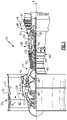
- FIG. 1 schematically illustrates a gas turbine engine 20.
- the gas turbine engine 20 is disclosed herein as a two-spool turbofan that generally incorporates a fan section 22, a compressor section 24, a combustor section 26 and a turbine section 28.
- the fan section 22 may include a single-stage fan 42 having a plurality of fan blades 43.
- the fan blades 43 may have a fixed stagger angle or may have a variable pitch to direct incoming airflow from an engine inlet.
- the fan 42 drives air along a bypass flow path B in a bypass duct 13 defined within a housing 15 such as a fan case or nacelle, and also drives air along a core flow path C for compression and communication into the combustor section 26 then expansion through the turbine section 28.
- a splitter 29 aft of the fan 42 divides the air between the bypass flow path B and the core flow path C.
- the housing 15 may surround the fan 42 to establish an outer diameter of the bypass duct 13.
- the splitter 29 may establish an inner diameter of the bypass duct 13.
- the exemplary engine 20 generally includes a low speed spool 30 and a high speed spool 32 mounted for rotation about an engine central longitudinal axis A relative to an engine static structure 36 via several bearing systems 38. It should be understood that various bearing systems 38 at various locations may alternatively or additionally be provided, and the location of bearing systems 38 may be varied as appropriate to the application.
- the low speed spool 30 generally includes an inner shaft 40 that interconnects, a first (or low) pressure compressor 44 and a first (or low) pressure turbine 46.
- the inner shaft 40 is connected to the fan 42 through a speed change mechanism, which in the exemplary gas turbine engine 20 is illustrated as a geared architecture 48 to drive the fan 42 at a lower speed than the low speed spool 30.
- the inner shaft 40 may interconnect the low pressure compressor 44 and low pressure turbine 46 such that the low pressure compressor 44 and low pressure turbine 46 are rotatable at a common speed and in a common direction.
- the low pressure turbine 46 drives both the fan 42 and low pressure compressor 44 through the geared architecture 48 such that the fan 42 and low pressure compressor 44 are rotatable at a common speed.
- the high speed spool 32 includes an outer shaft 50 that interconnects a second (or high) pressure compressor 52 and a second (or high) pressure turbine 54.
- a combustor 56 is arranged in the exemplary gas turbine 20 between the high pressure compressor 52 and the high pressure turbine 54.
- a mid-turbine frame 57 of the engine static structure 36 may be arranged generally between the high pressure turbine 54 and the low pressure turbine 46.
- the mid-turbine frame 57 further supports bearing systems 38 in the turbine section 28.
- the inner shaft 40 and the outer shaft 50 are concentric and rotate via bearing systems 38 about the engine central longitudinal axis A which is collinear with their longitudinal axes.
- Airflow in the core flow path C is compressed by the low pressure compressor 44 then the high pressure compressor 52, mixed and burned with fuel in the combustor 56, then expanded through the high pressure turbine 54 and low pressure turbine 46.
- the mid-turbine frame 57 includes airfoils 59 which are in the core flow path C.
- the turbines 46, 54 rotationally drive the respective low speed spool 30 and high speed spool 32 in response to the expansion.
- gear system 48 may be located aft of the low pressure compressor, or aft of the combustor section 26 or even aft of turbine section 28, and fan 42 may be positioned forward or aft of the location of gear system 48.
- the low pressure compressor 44, high pressure compressor 52, high pressure turbine 54 and low pressure turbine 46 each include one or more stages having a row of rotatable airfoils. Each stage may include a row of vanes adjacent the rotatable airfoils.
- the rotatable airfoils are schematically indicated at 47, and the vanes are schematically indicated at 49.
- the engine 20 may be a high-bypass geared aircraft engine.
- the bypass ratio can be greater than or equal to 10.0 and less than or equal to about 18.0, or more narrowly can be less than or equal to 16.0.
- the geared architecture 48 may be an epicyclic gear train, such as a planetary gear system or a star gear system.
- the epicyclic gear train may include a sun gear, a ring gear, a plurality of intermediate gears meshing with the sun gear and ring gear, and a carrier that supports the intermediate gears.
- the sun gear may provide an input to the gear train.
- the ring gear (e.g., star gear system) or carrier (e.g., planetary gear system) may provide an output of the gear train to drive the fan 42.
- a gear reduction ratio may be greater than or equal to 2.3, or more narrowly greater than or equal to 3.0, and in some embodiments the gear reduction ratio is greater than or equal to 3.4.
- the gear reduction ratio may be less than or equal to 4.0.
- the fan diameter is significantly larger than that of the low pressure compressor 44.
- the low pressure turbine 46 can have a pressure ratio that is greater than or equal to 8.0 and in some embodiments is greater than or equal to 10.0.
- the low pressure turbine pressure ratio can be less than or equal to 13.0, or more narrowly less than or equal to 12.0.
- Low pressure turbine 46 pressure ratio is pressure measured prior to an inlet of low pressure turbine 46 as related to the pressure at the outlet of the low pressure turbine 46 prior to an exhaust nozzle. It should be understood, however, that the above parameters are only exemplary of one embodiment of a geared architecture engine and that the present invention is applicable to other gas turbine engines including direct drive turbofans. All of these parameters are measured at the cruise condition described below.
- the fan section 22 of the engine 20 is designed for a particular flight condition -- typically cruise at about 0.8 Mach and about 35,000 feet (10,668 meters).
- the flight condition of 0.8 Mach and 35,000 ft (10,668 meters), with the engine at its best fuel consumption - also known as "bucket cruise Thrust Specific Fuel Consumption ('TSFC')" - is the industry standard parameter of lbm of fuel being burned divided by lbf of thrust the engine produces at that minimum point.
- 'TSFC' Thrust Specific Fuel Consumption
- Fan pressure ratio is the pressure ratio across the fan blade 43 alone, without a Fan Exit Guide Vane (“FEGV”) system.
- a distance is established in a radial direction between the inner and outer diameters of the bypass duct 13 at an axial position corresponding to a leading edge of the splitter 29 relative to the engine central longitudinal axis A.
- the fan pressure ratio is a spanwise average of the pressure ratios measured across the fan blade 43 alone over radial positions corresponding to the distance.
- the fan pressure ratio can be less than or equal to 1.45, or more narrowly greater than or equal to 1.25, such as between 1.30 and 1.40.
- the corrected fan tip speed can be less than or equal to 1150.0 ft / second (350.5 meters/second), and can be greater than or equal to 1000.0 ft / second (304.8 meters/second).
- FIG 2 shows a portion of an example turbine section 28, which may be incorporated into a gas turbine engine such as the one shown in Figure 1 .
- the turbine section 28 includes a plurality of alternating turbine blades 102 and turbine vanes 97.
- a turbine blade 102 has a radially outer tip 103 that is spaced from a blade outer air seal assembly 104 with a blade outer air seal ("BOAS") 106.
- the BOAS 106 may be mounted to an engine case or structure, such as engine static structure 36 via a control ring or support structure 110 and a carrier 112.
- the engine structure 36 may extend for a full 360° about the engine axis A.
- the turbine vane assembly 97 generally comprises a plurality of vane segments 118.
- each of the vane segments 118 has an airfoil 116 extending between an inner vane platform 120 and an outer vane platform 122.
- At least a portion of the outer vane platform 122 may be formed of a ceramic matrix composite material ("CMC") material.
- the outer vane platform 122 is formed of a plurality of CMC laminate sheets.
- the laminate sheets may be silicon carbide fibers, formed into a braided or woven fabric in each layer.
- the outer vane platform 122 may be made of a monolithic ceramic.
- CMC components such as platforms 120, 122 are formed by laying fiber material, such as laminate sheets or braids, in tooling, injecting a gaseous or a melt infiltrant into the tooling, and reacting to form a solid composite component.
- the component may be further processed by adding additional material to coat the laminate sheets.
- CMC components may have higher operating temperatures than components formed from other materials.
- a radially stacked assembly may be arranged between the platform 122 and the engine static structure 36, as explained further herein.
- FIG. 3 illustrates a portion of the vane ring assembly 97 from the turbine section 28 of the engine 20.
- the vane ring assembly 97 is made up of a plurality of vanes 118 situated in a circumferential row about the engine central axis A.
- the vane segments 118 are shown and described with reference to application in the turbine section 28, it is to be understood that the examples herein are also applicable to structural vanes in other sections of the engine 20.
- the vane segment 118 has an outer vane platform 122 radially outward of the airfoil 116.
- Each platform 122 has radially inner and outer sides R1, R2, respectively, first and second axial sides A1, A2, respectively, and first and second circumferential sides C1, C2, respectively.
- the radially inner side R1 faces in a direction toward the engine central axis A.
- the radially inner side R1 is thus the gas path side of the outer vane platform 122 that bounds a portion of the core flow path C.
- the first axial side A1 faces in a forward direction toward the front of the engine 20 (i.e., toward the fan 42), and the second axial side A2 faces in an aft direction toward the rear of the engine 20 (i.e., toward the exhaust end).
- the first axial side A1 is near the airfoil leading end 125 and the second axial side A2 is near the airfoil trailing end 121.
- the first and second circumferential sides C1, C2 of each platform 122 abut circumferential sides C1, C2 of adjacent platforms 122.
- generally axially means a direction having a vector component in the axial direction that is greater than a vector component in the circumferential direction
- generally radially means a direction having a vector component in the radial direction that is greater than a vector component in the axial direction
- generally circumferentially means a direction having a vector component in the circumferential direction that is greater than a vector component in the axial direction.
- an example turbine section 28 may apply to the compressor section.
- an outer vane platform 122 is described, this disclosure may apply to other components, and particularly flow path components. For example, this disclosure may apply to combustor liner panels, shrouds, transition ducts, exhaust nozzle liners, blade outer air seals, or other CMC components. Further, although the outer vane platform 122 is generally shown and referenced, this disclosure may apply to the inner vane platform 120.
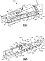
- Figure 4 illustrates a sealing assembly 103 arranged at an outer vane platform 122, such as the outer vane platform 122 of the vane assembly 97.
- the platform 122 may be formed of a CMC material, for example.
- a vane support or cover 124 is arranged adjacent the platform 122.
- the vane cover 124 may be radially outward of the platform 122, for example.
- the vane cover 124 may be a metallic material, for example.
- An engine structure, such as engine static structure 36 is arranged radially outward of the vane cover 124 and the platform 122.
- One or more radially stacked components may be arranged between the platform 122 and the engine structure 36 for positioning and/or sealing the components.
- the vane cover 124 may include a raised perimeter 127 that surrounds a base portion 126, for example.
- the raised perimeter 127 is on a radially outer side of the vane cover 124.
- the base portion 126 inward of the perimeter 127 may be cooled via impingement cooling, for example.
- a wall 128 may extend across the vane cover 124 in a circumferential direction. In this example, the wall 128 is aft of the airfoil 116.
- the raised perimeter 127 and wall 128 engage with other components to provide sealing between the vane cover 124 and the engine structure 36.
- the vane cover 124 has a protrusion 132 that provides a surface for engagement with a spring assembly 130.
- the spring assembly 130 may be secured to the engine structure 36, for example.
- the spring assembly 130 generally includes a spring housing 144 containing a spring 142 and a plunger 140 (shown in Figure 5 ).
- the plunger 140 is in contact with the protrusion 132 on the vane cover 124, for example.
- a spring cap 146 may be arranged outward of the spring housing 144 to secure the spring 142 within the housing 144.
- the spring cap 16 may be secured with bolts 148, for example.
- the spring 142 may be a compression spring, for example.
- the spring assembly 130 may load the components inboard, for example.
- a spar leg 134 may be secured to the engine structure 36 to provide support for an outer vane platform 122, for example.
- a metallic baffle 136 may be arranged on the vane cover 124 about the airfoil 116.
- forward and aft seals 150, 160 are arranged forward and aft of the vane cover 124, respectively.
- the forward and aft seals 150, 160 may be brush seals, for example.
- the forward and aft seals 150, 160 are arranged at the leading edge and trailing edge, respectively, and may reduce unnecessary tangential gaps resulting from segmented seals and reduce potential leakage to the gaspath from the platform impingement region by reducing the overall number of leak paths to the gaspath.
- the trailing edge seal 160 also seals with the blade outer air seal 105, and thus serves a dual-purpose.
- Figure 5 illustrates a cross-sectional view along line 5-5 of Figure 4 .
- This view shows the wall 128 defining a pocket or slot 129.
- the slot 129 extends into the wall 128 in a substantially radial direction.
- the platform 122 has a flange 123 that fits into the slot 129.
- the flange 123 extends radially outward from the platform 122 and may be integral with the platform 122, for example.
- the engine structure 36 has an inwardly extending flange 125 in engagement with the wall 128.
- the vane cover 124 has an aft flange 164 that may engage an aft portion 162 of the engine structure.
- the engine structure 36 also has a forward flange 152 that extends radially inward. The forward flange 152 may engage with a forward end 154 of the vane cover 124, for example.
- the wall 128 and flanges 123, 125 divide the area between the engine structure 36 and the vane cover 124 into a forward cavity 172 and an aft cavity 170.
- the forward and aft cavities 172, 170 are an impingement region, and provide impingement cooling to the vane cover 124 and platform 122.
- the disclosed arrangement provides sealing for these cavities 172, 170 to improve impingement cooling of the components.
- Figure 6 illustrates a portion of the exemplary vane identified in Figure 5 .
- This portion of assembly is near the trailing edge of the platform 122.
- a cavity or gap 180 is formed between the platform 122 and the vane cover 124.
- This cavity 180 may be formed as a recess in the platform 122, for example.
- the cavity 180 may have a height 193 between a floor 179 of the cavity 180 and the vane cover 124. In one example, the height 193 is between about 0.020 and 0.050 inches (0.508 to 1.27 mm).
- the cavity 180 may be formed from a local ply buildup around the perimeter of the platform 122, for example.
- the cavity 180 is formed by about four plies about the perimeter of the vane cover 124, though more or fewer may be used.
- the cavity 180 may extend in the axial direction to a same position as the base portion 126. In other words, an edge of the cavity 180 is axially aligned with the raised perimeter 127 of the vane cover 124.
- a plurality of impingement holes 181 extend through the vane cover 124 and communicate cooling air from the cavity 170 to the cavity 180 for impingement cooling of the platform 122.
- a slot 184 extends in a substantially radial direction into the platform 122.
- a slot 185 extends radially outward in the raised perimeter 127 of the vane cover 124.
- the slots 184, 185 are aligned in the axial direction.
- the slots 184, 185 may be machined into the platform 122 and vane cover 124, for example.
- a vertical featherseal 182 may be arranged in the slots 184, 185.
- the vertical featherseal 182 extends in a substantially radial direction, for example.
- the featherseal 182 may be a metallic material, for example.
- Additional vertical featherseals such as featherseal 183 (shown in Figure 5 ) may also be arranged between the platform 122 and the vane cover 124.
- Featherseals 182, 183 may surround a perimeter of the airfoil 116, for example.
- the vertical featherseal 182 may help to seal the impingement region, which may provide improved cooling effectiveness, for example.
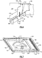
- FIG. 7 illustrates a view of a portion of the vane assembly.
- the outer structure 36, spar 134, and seal assembly 130 are removed to show details of the vane cover 124 and sealing arrangement.
- the wall 128 extends all the way across the vane cover 124 in the circumferential direction.
- a baffle 136 is arranged about the airfoil 116 to form an airfoil shaped cavity.
- the baffle 136 may be a metallic material and may be welded to the vane cover 124, for example.
- the baffle 136 seals off a high pressure source from the impingement region of the vane cover 124.
- Mateface seals 161, 163 may be arranged along the circumferential edges of the platform 122.
- the mateface seals 161, 163 may be sitting directly on the platform 122, for example.
- the mateface seals 161, 163 extend an entire axial length of the platform 122.
- the mateface seals 161, 163 may be seated in place by the forward and aft seals 150, 160, for example. This arrangement having leading and trailing edge seals, such as brush seals, and pressure and suction side mateface seals around the entire perimeter of the platform 122 to restrict leakage to the gaspath.
- a coating may be applied on a portion of the platform 122.
- the coating may be applied at the matefaces, or circumferential sides C1, C2, for example.
- the coating may be machinable. For example, a step may be machined into the coating to form a recess, and the mateface seal 163 fits in the recess. This arrangement positions the mateface seal further radially inward, which may allow for improved radial clearance and cooling.
- the disclosed arrangement helps to react out forces on the vane, provide effective sealing means, and provide impingement cooling.
- This arrangement provides an effective sealing by combining outer diameter perimeter leak paths, while preserving the ability to impinge on the platform's backside via the metallic cover plate.
- This arrangement also permits impingement within internal airfoil cavities via the baffle of the CMC cover.
- the arrangement allows the number, position, and size of flanges to vary based on the loading needs of a particular design.
- the arrangement ensures the impingement regions are segregated from the source pressure regions by utilizing vertical featherseals and allowing the baffles to be welded to the metallic cover.
- the metallic cover further maximizes the potential area coverage of backside platform impingement by eliminating spatially inhibiting features.
- the metallic cover and spring assembly further allow the backside platform impingement distance to be more precisely controlled by reducing the number of constituent dimensions in the tolerance stackup.
- Some known radially stacked assemblies have a large gap from the accumulated tolerances of each component.
- the disclosed spring assembly may ensure the components are biased inward and properly constrained. In engine operation, the pressure difference within the assembly exerts a force on the outboard side of the vane cover 124 and platform 122 to also aid in loading the components inboard.
- the trailing edge sealing arrangement may have several beneficial attributes, such as BOAS cooling flow metering.
Abstract
Description
- A gas turbine engine typically includes a fan section, a compressor section, a combustor section, and a turbine section. Air entering the compressor section is compressed and delivered into the combustion section where it is mixed with fuel and ignited to generate a high-speed exhaust gas flow. The high-speed exhaust gas flow expands through the turbine section to drive the compressor and the fan section.
- The compressor or turbine sections may include vanes mounted on vane platforms. Some vanes have been proposed made of ceramic matrix composite materials. Cooling and sealing such vanes may present challenges.
- In one aspect, there is provided a vane assembly that includes an airfoil extending from a platform. The platform has a flange that extends radially outward and circumferentially across the platform. A vane cover is arranged adjacent the platform that defines an impingement gap between the platform and the vane cover. The vane cover has a wall that defines a slot. The flange is arranged at least partially within the slot.
- In an embodiment according to the above, the wall extends circumferentially across the vane cover.
- In another embodiment according to any of the above, the wall is configured to engage with a radially inwardly extending flange of an engine static structure.
- In another embodiment according to any of the above, a plurality of holes extend through the vane cover and are in fluid communication with the impingement gap.
- In another embodiment according to any of the above, the impingement gap is between about 0.020 and 0.050 inches (0.508-1.27 mm).
- In another embodiment according to any of the above, the vane cover has a raised perimeter on a radially outer side.
- In another embodiment according to any of the above, a second slot is arranged in a portion of the raised perimeter. A vertical featherseal is arranged in the second slot.
- In another embodiment according to any of the above, the vane cover has a protrusion that provides a seal land and is configured to be in contact with a plunger of a spring assembly mounted on an engine static structure.
- In another embodiment according to any of the above, a mateface seal is arranged on the platform at a circumferential edge.
- In another embodiment according to any of the above, a brush seal is arranged along at least one of a forward end and an aft end of the platform.
- In another embodiment according to any of the above, a baffle is welded to the vane cover to seal an airfoil shaped cavity.
- In another embodiment according to any of the above, the platform is formed from a ceramic matrix composite material.
- In another embodiment according to any of the above, the vane cover is formed from a metallic material.
- There is also provided a gas turbine engine that includes a compressor section. A combustor is in fluid communication with the compressor section. A turbine section is in fluid communication with the combustor. At least one of the turbine section or the compressor section includes a vane that has an airfoil and a platform. The platform has a flange that extends radially outward and circumferentially across the platform. A vane cover is arranged adjacent the platform. The vane cover has raised perimeter on a radially outer side. The vane cover defines an impingement gap between the platform and the vane cover within the raised perimeter.
- In an embodiment according to the above, a wall extends circumferentially across the vane cover. The wall is engaged with a first flange that extends radially inwardly from an engine static structure.
- In another embodiment according to any of the above, the wall defines a slot. The flange of the platform is arranged within the slot.
- In another embodiment according to any of the above, the engine static structure has a second radially inwardly extending flange forward of the first flange.
- In another embodiment according to any of the above, a plurality of holes extend through the vane cover and are in fluid communication with the impingement gap.
- In another embodiment according to any of the above, a mateface seal is arranged on the platform at a circumferential edge. A brush seal is arranged along at least one of a forward end and an aft end of the platform.
- In another embodiment according to any of the above, the platform is formed from a ceramic matrix composite material. The vane cover is formed from a metallic material.
- The present disclosure may include any one or more of the individual features disclosed above and/or below alone or in any combination thereof.
-
-
Figure 1 schematically illustrates an example gas turbine engine. -
Figure 2 schematically illustrates an example turbine section. -
Figure 3 schematically illustrates a portion of a vane ring assembly. -
Figure 4 schematically illustrates a view of a portion of an exemplary vane platform assembly. -
Figure 5 schematically illustrates a cross-sectional view of an exemplary vane platform assembly taken along line 5-5 ofFigure 4 . -
Figure 6 schematically illustrates a portion of the example vane platform assembly. -
Figure 7 schematically illustrates a portion of the example vane platform assembly. -
Figure 1 schematically illustrates agas turbine engine 20. Thegas turbine engine 20 is disclosed herein as a two-spool turbofan that generally incorporates afan section 22, acompressor section 24, a combustor section 26 and aturbine section 28. Thefan section 22 may include a single-stage fan 42 having a plurality offan blades 43. Thefan blades 43 may have a fixed stagger angle or may have a variable pitch to direct incoming airflow from an engine inlet. Thefan 42 drives air along a bypass flow path B in abypass duct 13 defined within ahousing 15 such as a fan case or nacelle, and also drives air along a core flow path C for compression and communication into the combustor section 26 then expansion through theturbine section 28. Asplitter 29 aft of thefan 42 divides the air between the bypass flow path B and the core flow path C. Thehousing 15 may surround thefan 42 to establish an outer diameter of thebypass duct 13. Thesplitter 29 may establish an inner diameter of thebypass duct 13. Although depicted as a two-spool turbofan gas turbine engine in the disclosed nonlimiting embodiment, it should be understood that the concepts described herein are not limited to use with two-spool turbofans as the teachings may be applied to other types of turbine engines including three-spool architectures. Theengine 20 may incorporate a variable area nozzle for varying an exit area of the bypass flow path B and/or a thrust reverser for generating reverse thrust. - The
exemplary engine 20 generally includes alow speed spool 30 and ahigh speed spool 32 mounted for rotation about an engine central longitudinal axis A relative to an enginestatic structure 36 viaseveral bearing systems 38. It should be understood thatvarious bearing systems 38 at various locations may alternatively or additionally be provided, and the location ofbearing systems 38 may be varied as appropriate to the application. - The
low speed spool 30 generally includes aninner shaft 40 that interconnects, a first (or low) pressure compressor 44 and a first (or low)pressure turbine 46. Theinner shaft 40 is connected to thefan 42 through a speed change mechanism, which in the exemplarygas turbine engine 20 is illustrated as a gearedarchitecture 48 to drive thefan 42 at a lower speed than thelow speed spool 30. Theinner shaft 40 may interconnect the low pressure compressor 44 andlow pressure turbine 46 such that the low pressure compressor 44 andlow pressure turbine 46 are rotatable at a common speed and in a common direction. In other embodiments, thelow pressure turbine 46 drives both thefan 42 and low pressure compressor 44 through the gearedarchitecture 48 such that thefan 42 and low pressure compressor 44 are rotatable at a common speed. Although this application discloses gearedarchitecture 48, its teaching may benefit direct drive engines having no geared architecture. Thehigh speed spool 32 includes anouter shaft 50 that interconnects a second (or high)pressure compressor 52 and a second (or high)pressure turbine 54. Acombustor 56 is arranged in theexemplary gas turbine 20 between thehigh pressure compressor 52 and thehigh pressure turbine 54. Amid-turbine frame 57 of the enginestatic structure 36 may be arranged generally between thehigh pressure turbine 54 and thelow pressure turbine 46. Themid-turbine frame 57 furthersupports bearing systems 38 in theturbine section 28. Theinner shaft 40 and theouter shaft 50 are concentric and rotate via bearingsystems 38 about the engine central longitudinal axis A which is collinear with their longitudinal axes. - Airflow in the core flow path C is compressed by the low pressure compressor 44 then the
high pressure compressor 52, mixed and burned with fuel in thecombustor 56, then expanded through thehigh pressure turbine 54 andlow pressure turbine 46. Themid-turbine frame 57 includesairfoils 59 which are in the core flow path C. Theturbines low speed spool 30 andhigh speed spool 32 in response to the expansion. It will be appreciated that each of the positions of thefan section 22,compressor section 24, combustor section 26,turbine section 28, and fandrive gear system 48 may be varied. For example,gear system 48 may be located aft of the low pressure compressor, or aft of the combustor section 26 or even aft ofturbine section 28, andfan 42 may be positioned forward or aft of the location ofgear system 48. - The low pressure compressor 44,
high pressure compressor 52,high pressure turbine 54 andlow pressure turbine 46 each include one or more stages having a row of rotatable airfoils. Each stage may include a row of vanes adjacent the rotatable airfoils. The rotatable airfoils are schematically indicated at 47, and the vanes are schematically indicated at 49. - The
engine 20 may be a high-bypass geared aircraft engine. The bypass ratio can be greater than or equal to 10.0 and less than or equal to about 18.0, or more narrowly can be less than or equal to 16.0. The gearedarchitecture 48 may be an epicyclic gear train, such as a planetary gear system or a star gear system. The epicyclic gear train may include a sun gear, a ring gear, a plurality of intermediate gears meshing with the sun gear and ring gear, and a carrier that supports the intermediate gears. The sun gear may provide an input to the gear train. The ring gear (e.g., star gear system) or carrier (e.g., planetary gear system) may provide an output of the gear train to drive thefan 42. A gear reduction ratio may be greater than or equal to 2.3, or more narrowly greater than or equal to 3.0, and in some embodiments the gear reduction ratio is greater than or equal to 3.4. The gear reduction ratio may be less than or equal to 4.0. The fan diameter is significantly larger than that of the low pressure compressor 44. Thelow pressure turbine 46 can have a pressure ratio that is greater than or equal to 8.0 and in some embodiments is greater than or equal to 10.0. The low pressure turbine pressure ratio can be less than or equal to 13.0, or more narrowly less than or equal to 12.0.Low pressure turbine 46 pressure ratio is pressure measured prior to an inlet oflow pressure turbine 46 as related to the pressure at the outlet of thelow pressure turbine 46 prior to an exhaust nozzle. It should be understood, however, that the above parameters are only exemplary of one embodiment of a geared architecture engine and that the present invention is applicable to other gas turbine engines including direct drive turbofans. All of these parameters are measured at the cruise condition described below. - A significant amount of thrust is provided by the bypass flow B due to the high bypass ratio. The
fan section 22 of theengine 20 is designed for a particular flight condition -- typically cruise at about 0.8 Mach and about 35,000 feet (10,668 meters). The flight condition of 0.8 Mach and 35,000 ft (10,668 meters), with the engine at its best fuel consumption - also known as "bucket cruise Thrust Specific Fuel Consumption ('TSFC')" - is the industry standard parameter of lbm of fuel being burned divided by lbf of thrust the engine produces at that minimum point. The engine parameters described above, and those in the next paragraph are measured at this condition unless otherwise specified. - "Fan pressure ratio" is the pressure ratio across the
fan blade 43 alone, without a Fan Exit Guide Vane ("FEGV") system. A distance is established in a radial direction between the inner and outer diameters of thebypass duct 13 at an axial position corresponding to a leading edge of thesplitter 29 relative to the engine central longitudinal axis A. The fan pressure ratio is a spanwise average of the pressure ratios measured across thefan blade 43 alone over radial positions corresponding to the distance. The fan pressure ratio can be less than or equal to 1.45, or more narrowly greater than or equal to 1.25, such as between 1.30 and 1.40. "Corrected fan tip speed" is the actual fan tip speed in ft/sec divided by an industry standard temperature correction of [(Tram °R) / (518.7 °R)]0.5 (where °R = K x 9/5). The corrected fan tip speed can be less than or equal to 1150.0 ft / second (350.5 meters/second), and can be greater than or equal to 1000.0 ft / second (304.8 meters/second). -
Figure 2 shows a portion of anexample turbine section 28, which may be incorporated into a gas turbine engine such as the one shown inFigure 1 . However, it should be understood that other sections of thegas turbine engine 20 or other gas turbine engines, and even gas turbine engines not having a fan section at all, could benefit from this disclosure. Theturbine section 28 includes a plurality of alternatingturbine blades 102 andturbine vanes 97. - A
turbine blade 102 has a radiallyouter tip 103 that is spaced from a blade outerair seal assembly 104 with a blade outer air seal ("BOAS") 106. TheBOAS 106 may be mounted to an engine case or structure, such as enginestatic structure 36 via a control ring orsupport structure 110 and acarrier 112. Theengine structure 36 may extend for a full 360° about the engine axis A. - The
turbine vane assembly 97 generally comprises a plurality ofvane segments 118. In this example, each of thevane segments 118 has anairfoil 116 extending between aninner vane platform 120 and anouter vane platform 122. At least a portion of theouter vane platform 122 may be formed of a ceramic matrix composite material ("CMC") material. Theouter vane platform 122 is formed of a plurality of CMC laminate sheets. The laminate sheets may be silicon carbide fibers, formed into a braided or woven fabric in each layer. In other examples, theouter vane platform 122 may be made of a monolithic ceramic. CMC components such asplatforms platform 122 and the enginestatic structure 36, as explained further herein. -
Figure 3 illustrates a portion of thevane ring assembly 97 from theturbine section 28 of theengine 20. Thevane ring assembly 97 is made up of a plurality ofvanes 118 situated in a circumferential row about the engine central axis A. Although thevane segments 118 are shown and described with reference to application in theturbine section 28, it is to be understood that the examples herein are also applicable to structural vanes in other sections of theengine 20. - The
vane segment 118 has anouter vane platform 122 radially outward of theairfoil 116. Eachplatform 122 has radially inner and outer sides R1, R2, respectively, first and second axial sides A1, A2, respectively, and first and second circumferential sides C1, C2, respectively. The radially inner side R1 faces in a direction toward the engine central axis A. The radially inner side R1 is thus the gas path side of theouter vane platform 122 that bounds a portion of the core flow path C. The first axial side A1 faces in a forward direction toward the front of the engine 20 (i.e., toward the fan 42), and the second axial side A2 faces in an aft direction toward the rear of the engine 20 (i.e., toward the exhaust end). In other words, the first axial side A1 is near theairfoil leading end 125 and the second axial side A2 is near theairfoil trailing end 121. The first and second circumferential sides C1, C2 of eachplatform 122 abut circumferential sides C1, C2 ofadjacent platforms 122. - In this disclosure, "generally axially" means a direction having a vector component in the axial direction that is greater than a vector component in the circumferential direction, "generally radially" means a direction having a vector component in the radial direction that is greater than a vector component in the axial direction and "generally circumferentially" means a direction having a vector component in the circumferential direction that is greater than a vector component in the axial direction.
- Although an
example turbine section 28 is shown, this disclosure may apply to the compressor section. Although anouter vane platform 122 is described, this disclosure may apply to other components, and particularly flow path components. For example, this disclosure may apply to combustor liner panels, shrouds, transition ducts, exhaust nozzle liners, blade outer air seals, or other CMC components. Further, although theouter vane platform 122 is generally shown and referenced, this disclosure may apply to theinner vane platform 120. -
Figure 4 illustrates a sealingassembly 103 arranged at anouter vane platform 122, such as theouter vane platform 122 of thevane assembly 97. Theplatform 122 may be formed of a CMC material, for example. A vane support or cover 124 is arranged adjacent theplatform 122. Thevane cover 124 may be radially outward of theplatform 122, for example. Thevane cover 124 may be a metallic material, for example. An engine structure, such as enginestatic structure 36 is arranged radially outward of thevane cover 124 and theplatform 122. One or more radially stacked components may be arranged between theplatform 122 and theengine structure 36 for positioning and/or sealing the components. - The
vane cover 124 may include a raisedperimeter 127 that surrounds abase portion 126, for example. In this example, the raisedperimeter 127 is on a radially outer side of thevane cover 124. Thebase portion 126 inward of theperimeter 127 may be cooled via impingement cooling, for example. Awall 128 may extend across thevane cover 124 in a circumferential direction. In this example, thewall 128 is aft of theairfoil 116. The raisedperimeter 127 andwall 128 engage with other components to provide sealing between thevane cover 124 and theengine structure 36. - In some examples, the
vane cover 124 has aprotrusion 132 that provides a surface for engagement with aspring assembly 130. Thespring assembly 130 may be secured to theengine structure 36, for example. Thespring assembly 130 generally includes aspring housing 144 containing aspring 142 and a plunger 140 (shown inFigure 5 ). Theplunger 140 is in contact with theprotrusion 132 on thevane cover 124, for example. Aspring cap 146 may be arranged outward of thespring housing 144 to secure thespring 142 within thehousing 144. The spring cap 16 may be secured withbolts 148, for example. Thespring 142 may be a compression spring, for example. Thespring assembly 130 may load the components inboard, for example. - A
spar leg 134 may be secured to theengine structure 36 to provide support for anouter vane platform 122, for example. Ametallic baffle 136 may be arranged on thevane cover 124 about theairfoil 116. In some examples, forward andaft seals vane cover 124, respectively. The forward andaft seals aft seals edge seal 160 also seals with the bladeouter air seal 105, and thus serves a dual-purpose. -
Figure 5 illustrates a cross-sectional view along line 5-5 ofFigure 4 . This view shows thewall 128 defining a pocket orslot 129. Theslot 129 extends into thewall 128 in a substantially radial direction. Theplatform 122 has aflange 123 that fits into theslot 129. Theflange 123 extends radially outward from theplatform 122 and may be integral with theplatform 122, for example. In some examples, theengine structure 36 has an inwardly extendingflange 125 in engagement with thewall 128. Thevane cover 124 has anaft flange 164 that may engage anaft portion 162 of the engine structure. In the illustrated example, theengine structure 36 also has aforward flange 152 that extends radially inward. Theforward flange 152 may engage with aforward end 154 of thevane cover 124, for example. - The
wall 128 andflanges engine structure 36 and thevane cover 124 into aforward cavity 172 and anaft cavity 170. The forward andaft cavities vane cover 124 andplatform 122. There is a pressure differential between a space radially outward of thecavities engine structure 36 is higher than in thecavities cavities cavities -
Figure 6 illustrates a portion of the exemplary vane identified inFigure 5 . This portion of assembly is near the trailing edge of theplatform 122. In this example, a cavity orgap 180 is formed between theplatform 122 and thevane cover 124. Thiscavity 180 may be formed as a recess in theplatform 122, for example. Thecavity 180 may have aheight 193 between afloor 179 of thecavity 180 and thevane cover 124. In one example, theheight 193 is between about 0.020 and 0.050 inches (0.508 to 1.27 mm). Thecavity 180 may be formed from a local ply buildup around the perimeter of theplatform 122, for example. In one example, thecavity 180 is formed by about four plies about the perimeter of thevane cover 124, though more or fewer may be used. Thecavity 180 may extend in the axial direction to a same position as thebase portion 126. In other words, an edge of thecavity 180 is axially aligned with the raisedperimeter 127 of thevane cover 124. A plurality of impingement holes 181 extend through thevane cover 124 and communicate cooling air from thecavity 170 to thecavity 180 for impingement cooling of theplatform 122. - In some examples, a
slot 184 extends in a substantially radial direction into theplatform 122. Aslot 185 extends radially outward in the raisedperimeter 127 of thevane cover 124. Theslots slots platform 122 andvane cover 124, for example. Avertical featherseal 182 may be arranged in theslots vertical featherseal 182 extends in a substantially radial direction, for example. Thefeatherseal 182 may be a metallic material, for example. Additional vertical featherseals, such as featherseal 183 (shown inFigure 5 ) may also be arranged between theplatform 122 and thevane cover 124.Featherseals airfoil 116, for example. Thevertical featherseal 182 may help to seal the impingement region, which may provide improved cooling effectiveness, for example. -
Figure 7 illustrates a view of a portion of the vane assembly. In this view, theouter structure 36,spar 134, and sealassembly 130 are removed to show details of thevane cover 124 and sealing arrangement. In this example, thewall 128 extends all the way across thevane cover 124 in the circumferential direction. Abaffle 136 is arranged about theairfoil 116 to form an airfoil shaped cavity. Thebaffle 136 may be a metallic material and may be welded to thevane cover 124, for example. Thebaffle 136 seals off a high pressure source from the impingement region of thevane cover 124. - Mateface seals 161, 163 may be arranged along the circumferential edges of the
platform 122. The mateface seals 161, 163 may be sitting directly on theplatform 122, for example. The mateface seals 161, 163 extend an entire axial length of theplatform 122. The mateface seals 161, 163 may be seated in place by the forward andaft seals platform 122 to restrict leakage to the gaspath. - In some examples, a coating may be applied on a portion of the
platform 122. The coating may be applied at the matefaces, or circumferential sides C1, C2, for example. The coating may be machinable. For example, a step may be machined into the coating to form a recess, and themateface seal 163 fits in the recess. This arrangement positions the mateface seal further radially inward, which may allow for improved radial clearance and cooling. - The disclosed arrangement helps to react out forces on the vane, provide effective sealing means, and provide impingement cooling. This arrangement provides an effective sealing by combining outer diameter perimeter leak paths, while preserving the ability to impinge on the platform's backside via the metallic cover plate. This arrangement also permits impingement within internal airfoil cavities via the baffle of the CMC cover. The arrangement allows the number, position, and size of flanges to vary based on the loading needs of a particular design. The arrangement ensures the impingement regions are segregated from the source pressure regions by utilizing vertical featherseals and allowing the baffles to be welded to the metallic cover. The metallic cover further maximizes the potential area coverage of backside platform impingement by eliminating spatially inhibiting features. The metallic cover and spring assembly further allow the backside platform impingement distance to be more precisely controlled by reducing the number of constituent dimensions in the tolerance stackup. Some known radially stacked assemblies have a large gap from the accumulated tolerances of each component. The disclosed spring assembly may ensure the components are biased inward and properly constrained. In engine operation, the pressure difference within the assembly exerts a force on the outboard side of the
vane cover 124 andplatform 122 to also aid in loading the components inboard. The trailing edge sealing arrangement may have several beneficial attributes, such as BOAS cooling flow metering. - Although a combination of features is shown in the illustrated examples, not all of them need to be combined to realize the benefits of various embodiments of this disclosure. In other words, a system designed according to an embodiment of this disclosure will not necessarily include all of the features shown in any one of the figures or all of the portions schematically shown in the figures. Moreover, selected features of one example embodiment may be combined with selected features of other example embodiments.
- Although an embodiment of this invention has been disclosed, a worker of ordinary skill in this art would recognize that certain modifications would come within the scope of this disclosure. For that reason, the following claims should be studied to determine the true scope and content of this disclosure.
Claims (15)
- A vane assembly (97), comprising:an airfoil (116) extending from a platform (122), the platform (122) having a flange (123) extending radially outward and circumferentially across the platform (122); anda vane cover (124) arranged adjacent the platform (122) that defines an impingement gap (193) between the platform (122) and the vane cover (124), the vane cover (124) having a wall (128) that defines a slot (129), the flange (123) arranged at least partially within the slot (129).
- The vane assembly of claim 1, wherein the wall (128) extends circumferentially across the vane cover (124).
- The vane assembly of claim 1 or 2, wherein the wall (128) is configured to engage with a radially inwardly extending flange (125) of an engine static structure (36).
- The vane assembly of any preceding claim, wherein the impingement gap (193) is between about 0.020 and 0.050 inches (0.508-1.27 mm).
- The vane assembly of any preceding claim, wherein the vane cover (124) has a raised perimeter (127) on a radially outer side.
- The vane assembly of claim 5, wherein a second slot (185) is arranged in a portion of the raised perimeter (127), and a vertical featherseal (182) is arranged in the second slot (185).
- The vane assembly of any preceding claim, wherein the vane cover (124) has a protrusion (132) that provides a seal land and is configured to be in contact with a plunger (140) of a spring assembly (130) mounted on an or the engine static structure (36).
- The vane assembly of any preceding claim, wherein a baffle (136) is welded to the vane cover (124) to seal an airfoil shaped cavity.
- A gas turbine engine (20), comprising:a compressor section (24);a combustor (56) in fluid communication with the compressor section (24); anda turbine section (28) in fluid communication with the combustor (56),at least one of the turbine section (28) or the compressor section (24) comprising:a vane (97) having an airfoil (116) and a platform (122), the platform having a flange (123) extending radially outward and circumferentially across the platform (122); anda vane cover (124) arranged adjacent the platform (122), the vane cover (124) having raised perimeter (127) on a radially outer side, the vane cover (124) defines an impingement gap (193) between the platform (122) and the vane cover (124) within the raised perimeter (127).
- The gas turbine engine of claim 9, wherein a wall (128) extends circumferentially across the vane cover (124), and the wall (128) is engaged with a first flange (125) that extends radially inwardly from an engine static structure (36).
- The gas turbine engine of claim 9 or 10, wherein the wall (128) defines a slot (129), and the flange (123) of the platform (122) is arranged within the slot (129).
- The gas turbine engine of claim 10 or claim 11 as dependent on claim 10, wherein the engine static structure (36) has a second radially inwardly extending flange (152) forward of the first flange (125).
- The vane assembly or gas turbine engine of any preceding claim, wherein a plurality of holes (181) extend through the vane cover (124) and are in fluid communication with the impingement gap (193).
- The vane assembly, or gas turbine engine of any preceding claim, wherein:a mateface seal (161, 163) is arranged on the platform (122) at a circumferential edge; and/ora brush seal (150, 160) is arranged along at least one of a forward end and an aft end of the platform (122).
- The vane assembly or gas turbine engine of any preceding claim, wherein:the platform (122) is formed from a ceramic matrix composite material; and/orthe vane cover (124) is formed from a metallic material.
Applications Claiming Priority (1)
| Application Number | Priority Date | Filing Date | Title |
|---|---|---|---|
| US17/307,106 US11808176B2 (en) | 2021-05-04 | 2021-05-04 | CMC vane sealing arrangement |
Publications (2)
| Publication Number | Publication Date |
|---|---|
| EP4086434A2 true EP4086434A2 (en) | 2022-11-09 |
| EP4086434A3 EP4086434A3 (en) | 2023-01-25 |
Family
ID=81388976
Family Applications (1)
| Application Number | Title | Priority Date | Filing Date |
|---|---|---|---|
| EP22170311.9A Pending EP4086434A3 (en) | 2021-05-04 | 2022-04-27 | Cmc vane with platform cover |
Country Status (2)
| Country | Link |
|---|---|
| US (1) | US11808176B2 (en) |
| EP (1) | EP4086434A3 (en) |
Family Cites Families (12)
| Publication number | Priority date | Publication date | Assignee | Title |
|---|---|---|---|---|
| GB9305012D0 (en) * | 1993-03-11 | 1993-04-28 | Rolls Royce Plc | Sealing structures for gas turbine engines |
| US8096758B2 (en) * | 2008-09-03 | 2012-01-17 | Siemens Energy, Inc. | Circumferential shroud inserts for a gas turbine vane platform |
| US8292573B2 (en) * | 2009-04-21 | 2012-10-23 | General Electric Company | Flange cooled turbine nozzle |
| US20130011265A1 (en) * | 2011-07-05 | 2013-01-10 | Alstom Technology Ltd. | Chevron platform turbine vane |
| US9657642B2 (en) | 2014-03-27 | 2017-05-23 | Honeywell International Inc. | Turbine sections of gas turbine engines with dual use of cooling air |
| US9995157B2 (en) * | 2014-04-04 | 2018-06-12 | United Technologies Corporation | Gas turbine engine turbine vane platform cooling |
| EP3232002A1 (en) * | 2016-04-11 | 2017-10-18 | Rolls-Royce Corporation | Impingement plate with stress relief feature |
| CN111226023B (en) * | 2017-08-22 | 2022-06-14 | 西门子能源全球两合公司 | Rim sealing device |
| US10738620B2 (en) * | 2018-04-18 | 2020-08-11 | Raytheon Technologies Corporation | Cooling arrangement for engine components |
| US11073039B1 (en) | 2020-01-24 | 2021-07-27 | Rolls-Royce Plc | Ceramic matrix composite heat shield for use in a turbine vane and a turbine shroud ring |
| US11365642B2 (en) | 2020-04-09 | 2022-06-21 | Raytheon Technologies Corporation | Vane support system with seal |
| US11346228B1 (en) * | 2021-02-23 | 2022-05-31 | Raytheon Technologies Corporation | Airfoil with flange formed of wishbone-shaped fiber layer structure |
-
2021
- 2021-05-04 US US17/307,106 patent/US11808176B2/en active Active
-
2022
- 2022-04-27 EP EP22170311.9A patent/EP4086434A3/en active Pending
Also Published As
| Publication number | Publication date |
|---|---|
| US11808176B2 (en) | 2023-11-07 |
| US20220356809A1 (en) | 2022-11-10 |
| EP4086434A3 (en) | 2023-01-25 |
Similar Documents
| Publication | Publication Date | Title |
|---|---|---|
| EP3819475A1 (en) | Blade outer air seal arrangement and method of sealing | |
| EP2961943B1 (en) | Method and apparatus for handling pre-diffuser flow to a bearing compartment | |
| EP3066318B1 (en) | Inner diffuser case for a gas turbine engine | |
| EP4086436A1 (en) | Gas turbine vane assembly | |
| EP3620616B1 (en) | Turbine section with boas cooling air flow guide | |
| US11021986B2 (en) | Seal assembly for gas turbine engine | |
| US11454129B1 (en) | CMC component flow discourager flanges | |
| US11365644B2 (en) | Double box boas and carrier system | |
| EP3708784B1 (en) | Blade outer air seal assembly with cooling supply | |
| US11808176B2 (en) | CMC vane sealing arrangement | |
| US11898450B2 (en) | Flowpath assembly for gas turbine engine | |
| EP4056811A1 (en) | Scalloped mateface seal arrangement for cmc platforms | |
| EP4086435A1 (en) | Variable thickness machinable coating for platform seals | |
| EP4056812A1 (en) | Chevron grooved mateface seal | |
| US11781432B2 (en) | Nested vane arrangement for gas turbine engine | |
| US11125099B2 (en) | Boas arrangement with double dovetail attachments | |
| EP3748131A1 (en) | Boas flow directing arrangement |
Legal Events
| Date | Code | Title | Description |
|---|---|---|---|
| PUAI | Public reference made under article 153(3) epc to a published international application that has entered the european phase |
Free format text: ORIGINAL CODE: 0009012 |
|
| STAA | Information on the status of an ep patent application or granted ep patent |
Free format text: STATUS: THE APPLICATION HAS BEEN PUBLISHED |
|
| AK | Designated contracting states |
Kind code of ref document: A2 Designated state(s): AL AT BE BG CH CY CZ DE DK EE ES FI FR GB GR HR HU IE IS IT LI LT LU LV MC MK MT NL NO PL PT RO RS SE SI SK SM TR |
|
| PUAL | Search report despatched |
Free format text: ORIGINAL CODE: 0009013 |
|
| AK | Designated contracting states |
Kind code of ref document: A3 Designated state(s): AL AT BE BG CH CY CZ DE DK EE ES FI FR GB GR HR HU IE IS IT LI LT LU LV MC MK MT NL NO PL PT RO RS SE SI SK SM TR |
|
| RIC1 | Information provided on ipc code assigned before grant |
Ipc: F01D 9/06 20060101ALI20221222BHEP Ipc: F01D 9/04 20060101AFI20221222BHEP |
|
| STAA | Information on the status of an ep patent application or granted ep patent |
Free format text: STATUS: REQUEST FOR EXAMINATION WAS MADE |
|
| 17P | Request for examination filed |
Effective date: 20230717 |
|
| RBV | Designated contracting states (corrected) |
Designated state(s): AL AT BE BG CH CY CZ DE DK EE ES FI FR GB GR HR HU IE IS IT LI LT LU LV MC MK MT NL NO PL PT RO RS SE SI SK SM TR |
|
| RAP3 | Party data changed (applicant data changed or rights of an application transferred) |
Owner name: RTX CORPORATION |