EP4067557B1 - Clothes dryer - Google Patents
Clothes dryer Download PDFInfo
- Publication number
- EP4067557B1 EP4067557B1 EP21188353.3A EP21188353A EP4067557B1 EP 4067557 B1 EP4067557 B1 EP 4067557B1 EP 21188353 A EP21188353 A EP 21188353A EP 4067557 B1 EP4067557 B1 EP 4067557B1
- Authority
- EP
- European Patent Office
- Prior art keywords
- evaporator
- condenser
- air
- reversing valve
- working medium
- Prior art date
- Legal status (The legal status is an assumption and is not a legal conclusion. Google has not performed a legal analysis and makes no representation as to the accuracy of the status listed.)
- Active
Links
Images

Classifications
-
- D—TEXTILES; PAPER
- D06—TREATMENT OF TEXTILES OR THE LIKE; LAUNDERING; FLEXIBLE MATERIALS NOT OTHERWISE PROVIDED FOR
- D06F—LAUNDERING, DRYING, IRONING, PRESSING OR FOLDING TEXTILE ARTICLES
- D06F58/00—Domestic laundry dryers
- D06F58/20—General details of domestic laundry dryers
- D06F58/206—Heat pump arrangements
-
- D—TEXTILES; PAPER
- D06—TREATMENT OF TEXTILES OR THE LIKE; LAUNDERING; FLEXIBLE MATERIALS NOT OTHERWISE PROVIDED FOR
- D06F—LAUNDERING, DRYING, IRONING, PRESSING OR FOLDING TEXTILE ARTICLES
- D06F34/00—Details of control systems for washing machines, washer-dryers or laundry dryers
- D06F34/04—Signal transfer or data transmission arrangements
- D06F34/05—Signal transfer or data transmission arrangements for wireless communication between components, e.g. for remote monitoring or control
-
- D—TEXTILES; PAPER
- D06—TREATMENT OF TEXTILES OR THE LIKE; LAUNDERING; FLEXIBLE MATERIALS NOT OTHERWISE PROVIDED FOR
- D06F—LAUNDERING, DRYING, IRONING, PRESSING OR FOLDING TEXTILE ARTICLES
- D06F58/00—Domestic laundry dryers
- D06F58/20—General details of domestic laundry dryers
-
- D—TEXTILES; PAPER
- D06—TREATMENT OF TEXTILES OR THE LIKE; LAUNDERING; FLEXIBLE MATERIALS NOT OTHERWISE PROVIDED FOR
- D06F—LAUNDERING, DRYING, IRONING, PRESSING OR FOLDING TEXTILE ARTICLES
- D06F58/00—Domestic laundry dryers
- D06F58/20—General details of domestic laundry dryers
- D06F58/22—Lint collecting arrangements
-
- D—TEXTILES; PAPER
- D06—TREATMENT OF TEXTILES OR THE LIKE; LAUNDERING; FLEXIBLE MATERIALS NOT OTHERWISE PROVIDED FOR
- D06F—LAUNDERING, DRYING, IRONING, PRESSING OR FOLDING TEXTILE ARTICLES
- D06F58/00—Domestic laundry dryers
- D06F58/20—General details of domestic laundry dryers
- D06F58/24—Condensing arrangements
-
- D—TEXTILES; PAPER
- D06—TREATMENT OF TEXTILES OR THE LIKE; LAUNDERING; FLEXIBLE MATERIALS NOT OTHERWISE PROVIDED FOR
- D06F—LAUNDERING, DRYING, IRONING, PRESSING OR FOLDING TEXTILE ARTICLES
- D06F58/00—Domestic laundry dryers
- D06F58/32—Control of operations performed in domestic laundry dryers
- D06F58/34—Control of operations performed in domestic laundry dryers characterised by the purpose or target of the control
- D06F58/36—Control of operational steps, e.g. for optimisation or improvement of operational steps depending on the condition of the laundry
- D06F58/38—Control of operational steps, e.g. for optimisation or improvement of operational steps depending on the condition of the laundry of drying, e.g. to achieve the target humidity
-
- D—TEXTILES; PAPER
- D06—TREATMENT OF TEXTILES OR THE LIKE; LAUNDERING; FLEXIBLE MATERIALS NOT OTHERWISE PROVIDED FOR
- D06F—LAUNDERING, DRYING, IRONING, PRESSING OR FOLDING TEXTILE ARTICLES
- D06F58/00—Domestic laundry dryers
- D06F58/32—Control of operations performed in domestic laundry dryers
- D06F58/34—Control of operations performed in domestic laundry dryers characterised by the purpose or target of the control
- D06F58/45—Cleaning or disinfection of machine parts, e.g. of heat exchangers or filters
-
- D—TEXTILES; PAPER
- D06—TREATMENT OF TEXTILES OR THE LIKE; LAUNDERING; FLEXIBLE MATERIALS NOT OTHERWISE PROVIDED FOR
- D06F—LAUNDERING, DRYING, IRONING, PRESSING OR FOLDING TEXTILE ARTICLES
- D06F2105/00—Systems or parameters controlled or affected by the control systems of washing machines, washer-dryers or laundry dryers
- D06F2105/26—Heat pumps
-
- D—TEXTILES; PAPER
- D06—TREATMENT OF TEXTILES OR THE LIKE; LAUNDERING; FLEXIBLE MATERIALS NOT OTHERWISE PROVIDED FOR
- D06F—LAUNDERING, DRYING, IRONING, PRESSING OR FOLDING TEXTILE ARTICLES
- D06F2105/00—Systems or parameters controlled or affected by the control systems of washing machines, washer-dryers or laundry dryers
- D06F2105/54—Changing between normal operation mode and special operation modes, e.g. service mode, component cleaning mode or stand-by mode
-
- D—TEXTILES; PAPER
- D06—TREATMENT OF TEXTILES OR THE LIKE; LAUNDERING; FLEXIBLE MATERIALS NOT OTHERWISE PROVIDED FOR
- D06F—LAUNDERING, DRYING, IRONING, PRESSING OR FOLDING TEXTILE ARTICLES
- D06F58/00—Domestic laundry dryers
- D06F58/02—Domestic laundry dryers having dryer drums rotating about a horizontal axis
Definitions
- the present invention relates to a technical field of clothes drying, and in particular, to a clothes dryer.
- Clothes dryers such as a heat pump clothes dryer, work in the way that a motor drives a blower impeller to rotate so that air circulates in a directional air duct of a machine body, and when wet clothes are put into a tumbler, dry hot air is generated by using a compressor and a heat exchanger and then enters the tumbler to heat the clothes so as to take away water vapor.
- the existing heat pump clothes dryer includes a mesh filter installed at a front end of an evaporator in a heat exchanger. The mesh filter is configured to prevent flocks and debris from being first attached to the evaporator after the debris has left the tumbler.
- EP2497856A1 discloses a laundry-drier machine which comprises ventilation means, including a fan, for generating a forced flow of air, and heating means, preferably including a heat pump, for heating the air of the forced flow;
- the machine has a control system including a control unit, provided for controlling execution of a plurality of operating programs, and a user interface, which has selection means for selecting a desired operating program;
- the operating programs comprise operating programs which end upon achievement of a condition detectable by the control system, said programs comprise at least one first operating program for which the aforesaid condition is a condition of the door of the machine, the control system is prearranged for bringing and maintaining, during the at least one first program, the air of the forced flow to a substantially predetermined temperature and for causing ending of the at least one first
- JP4531414B2 discloses a laundry washer/dryer having a washing means which can evenly spray an aqueous solution for washing a heat sink and a radiator, which are heat exchangers, and can wash the surface of the heat exchangers for preventing corrosion and removing lint adhering to surface of the heat exchangers.
- the technical problem to be solved by the present invention is to provide a clothes dryer capable of performing self-cleaning.
- the technical solution adopted by the present invention to solve its technical problem is to provide a clothes dryer, including a housing, a tumbler and a heat exchange component.
- the housing has an air cavity therein.
- the air cavity and the tumbler form a closed-loop air duct.
- a blower impeller for driving air in the closed-loop air duct to flow is provided in the housing.
- the heat exchange component includes a compressor, and a condenser and an evaporator.
- the condenser and the evaporator are arranged inside the air cavity.
- the compressor is used to compress a working medium into a high temperature and high pressure state.
- the condenser communicates with the evaporator through a throttle capillary.
- the heat exchange component further includes a reversing valve.
- the reversing valve can switch between two modes through a remote control program.
- a first mode the working medium can flow from the compressor to the condenser via the reversing valve, the working medium in the condenser flows into the evaporator, and the working medium in the evaporator flows back to the compressor via the reversing valve.
- a second mode the working medium can flow from the compressor to the evaporator via the reversing valve, the working medium in the evaporator flows into the condenser, and the working medium in the condenser flows back to the compressor via the reversing valve.
- the clothes dryer has a cleaning mode being configured to switch the reversing valve to the first mode and to stop rotating the blower impeller such that the water vapor in the air condenses and frosts on the surface of the evaporator, wherein the cleaning mode is further configured to, after running for a period of time, to control the reversing valve to switch to second mode using the control program to thaw the previous frost on the surface of the evaporator into liquid water.
- blower impeller is installed in the air cavity, the blower impeller is near to one end of the air cavity, and a motor for driving the blower impeller to rotate is installed in the housing corresponding to the blower impeller.
- blower cover is installed at the back of the housing, the blower cover covers the one end of the air cavity near to the blower impeller and one end of the tumbler, and the other end of the tumbler communicates with the other end of the air cavity.
- the housing is provided with a mesh filter located in the air cavity therein.
- the compressor is fixedly installed on the bottom of the housing, and the compressor has an air discharge pipe for discharging the working medium and an air return pipe for backflow of the working medium thereon.
- the evaporator is located at a front end of the air duct of the air cavity relative to the condenser.
- a condenser is provided with a condenser connection pipe, and the condenser connection pipe and the throttle capillary are connected to both ends of an inner duct of the condenser, respectively.
- the evaporator has an evaporator connection pipe thereon, the evaporator connection pipe is connected to one end of an inner duct of the evaporator, and the other end of the inner duct of the evaporator is connected to the other end of the throttle capillary.
- the reversing valve is a four-way reversing valve.
- each of the air discharge pipe, the air return pipe, the condenser connection pipe and the evaporator connection pipe is connected to the reversing valve.
- the heat exchange component further includes the reversing valve, and the reversing valve can switch between two modes.
- the working medium flows from the compressor to the condenser via the reversing valve
- the working medium in the condenser flows into the evaporator
- the working medium in the evaporator flows back to the compressor via the reversing valve.
- the working medium flows from the compressor to the evaporator via the reversing valve
- the working medium in the evaporator flows into the condenser
- the working medium in the condenser flows back to the compressor via the reversing valve.
- the reversing valve in the heat exchange component switches to the first mode and the blower impeller is controlled to stop rotating, so that the high temperature and high pressure working medium that enters the condenser is converted to the low temperature and low pressure working medium by the throttle capillary and then enters the evaporator, thereby decreasing a temperature of the evaporator and condensing water vapor in the air to frost on a surface of the evaporator.
- a control program controls the reversing valve to switch to the second mode.
- the high temperature and high pressure working medium flows into the evaporator and then the evaporator is in a high temperature state so that the frost on the surface of the evaporator thaws into liquid water, and the liquid water flows downward to drive the flocks attached to the surface of the evaporator to fall off.
- the blower impeller is started to circulate the air between the tumbler and the air cavity after the air is heated up via the evaporator, and then the hot air blows the flocks remaining on the surface of the evaporator to clean the surface of the evaporator more thoroughly, thereby implementing self-cleaning.
- the present invention provides a clothes dryer, including the housing 1, and the tumbler 2 and the heat exchange component 3 installed in the housing 1. Air in the clothes dryer circulates between the tumbler 2 and the heat exchange component 3 to dry clothes in the tumbler 2.
- the tumbler 2 is rotatably installed in the housing 1.
- a bottom of the housing 1 has the air cavity 11, the air cavity 11 is located below the tumbler 2, and the air cavity 11 and the tumbler 2 form a closed-loop air duct.
- the blower impeller 12 located in the air cavity 11 is installed in the housing 1, and the blower impeller 12 is used to drive the air in the closed-loop air duct to flow.
- the blower impeller 12 is near to one end of the air cavity 11, and a motor is installed in the housing 1 corresponding to the blower impeller 12 and is configured for driving the blower impeller 12 to rotate so as to drive the air to flow.
- the one end of the air cavity 11 near to the blower impeller 12 communicates with one end of the tumbler 2. As shown in FIG.
- the blower cover 14 is installed at a back of the housing 1, the blower cover 14 covers the one end of the air cavity 11 near to the blower impeller 12 and the one end of the tumbler 2, and the other end of the tumbler 2 communicates with the other end of the air cavity 11 such that the air cavity 11 and the tumbler 2 form the closed-loop air duct, and the air circulates between the tumbler 2 and the heat exchange component 3 under the driving of the blower impeller 12.
- the mesh filter 13 located in the air cavity 11 is further installed in the housing 1 and the mesh filter 13 is located behind the evaporator 33.
- the mesh filter 13 is used to block impurities from entering the tumbler 2 and contaminating the tumbler 2, and does not function to filter the impurities for the evaporator 33 and the condenser 32 in the heat exchange component 3.
- the mesh number of the mesh filter 13 is not specifically required.
- the mesh filter 13 is located between the condenser 32 and the blower impeller 12.
- the heat exchange component 3 includes the compressor 31, the condenser 32, the evaporator 33 and the reversing valve 34.
- the compressor 31 is fixedly installed on a bottom of the housing 1.
- the compressor 31 has the air discharge pipe 311 and the air return pipe 312 thereon.
- the compressor 31 is used to compress the low temperature and low pressure working medium (such as a refrigerant) to a high temperature and high pressure state and then discharge it via the air discharge pipe 311.
- the air return pipe 312 is configured for the working medium to flow into the compressor 31.
- the condenser 32 and the evaporator 33 are accommodated in the air cavity 11, and the condenser 32 and the evaporator 33 are distributed inside the air cavity 11 along a length direction of the air cavity 11.
- the evaporator 33 is located at a front end of the air duct of the air cavity 11 relative to the condenser 32.
- the condenser 32 has the condenser connection pipe 321 and the throttle capillary 322 thereon.
- the condenser connection pipe 321 and the throttle capillary 322 are respectively connected to both ends of an inner duct of the condenser 32.
- the throttle capillary 322 communicates with the condenser 32 and the evaporator 33.
- the evaporator 33 has the evaporator connection pipe 331 thereon.
- the evaporator connection pipe 331 is connected to one end of an inner duct of the evaporator 33, and the other end of the inner duct of the evaporator 33 is connected to the other end of the throttle capillary 322. Accordingly, the working medium can flow between the condenser 32 and the evaporator 33 through the throttle capillary 322.
- the reversing valve 34 is a four-way reversing valve, where one end of each of the air discharge pipe 311, the air return pipe 312, the condenser connection pipe 321 and the evaporator connection pipe 331 is connected to the reversing valve 34, thereby controlling the reversing valve to switch between two modes.
- the working medium flows from the air discharge pipe 311 into the condenser connection pipe 321 via the reversing valve 34, the working medium in the condenser 32 flows into the evaporator 33, and the working medium flows from the evaporator connection pipe 331 into the air return pipe 312 via the reversing valve 34; in a second mode, the working medium can flow from the air discharge pipe 311 into the evaporator connection pipe 331 via the reversing valve 34, the working medium in the evaporator 33 flows into the condenser 32, and the working medium flows from the condenser connection pipe 321 into the air return pipe 312 via the reversing valve 34.
- the reversing valve 34 in the heat exchange component 3 is in the first mode.
- the compressor 31 compresses the working medium from a low temperature and low pressure state to a high temperature and high pressure state
- the high temperature and high pressure working medium passes through the air discharge pipe 311 and flows into the condenser 32 via the condenser connection pipe 321 so as to make the condenser 32 in a high temperature state.
- the working medium is throttled by the throttle capillary 322 after flowing through the condenser 32 and becomes the low temperature and low pressure state, and then the low temperature and low pressure working medium enters the evaporator 33 so as to make the evaporator 33 in a low temperature state.
- the low temperature and low pressure working medium flows from the evaporator connection pipe 331 into the air return pipe 312 via the reversing valve 34, the working medium returns to the compressor 31 through the air return pipe 312, and the heat exchange component 3 completes the cycle.
- the blower impeller 12 is working at the same time to drive the air to directionally circulate between the tumbler 2 and the heat exchange component 3. Specifically, the air enters the tumbler 2 through the blower cover 14 after the air is heated up by the high temperature condenser 32, and then the hot air is in contact with the wet clothes in the tumbler 2 and then takes away water vapor.
- the moist air enters the air cavity 11 again and first contacts the low temperature evaporator 33 such that the water vapor in the moist air contacts a surface of the evaporator 33 to be liquefied into liquid water, and then the liquid water drips off from the evaporator 33 and is collected.
- the dry air without moisture is heated up through the condenser 32 and then enters the tumbler 2 again for drying. Such a cycle is repeated to complete the drying of the clothes.
- the clothes dryer When the clothes dryer is not in use, it switches to a cleaning mode.
- the reversing valve 34 in the heat exchange component 3 is in the first mode, the blower impeller 12 stops rotating.
- the hot air does not circulate through the evaporator 33, the surface temperature of the evaporator 33 drops sharply such that the water vapor in the air condenses and frosts on the surface of the evaporator 33.
- the control program of the clothes dryer controls the reversing valve 34 to the second mode.
- the evaporator 33 is in the high temperature state to thaw the previous frost on the surface of the evaporator 33 into liquid water.
- the liquid water flows downward to drive the flocks attached to the surface of the evaporator 33 to fall off.
- the blower impeller 12 is started, so that the air circulates between the tumbler 2 and the air cavity 11 after the air is heated up through the evaporator 33.
- the hot air blows the flocks remaining on the surface of the evaporator 33 to further clean up the surface of the evaporator 33. Since the reversing valve 34 was in the first mode previously, most of water vapor inside the clothes dryer has been liquefied and collected, the humidity of the clothes dryer is relatively low. At the time, it is not easy to generate a large amount of condensed water on the surface of the condenser 32.
- the condenser 32 is located behind the high temperature evaporator 33, so that the circulated hot air will continuously dry the evaporator 33 and the condenser 32, and the flocks remaining on the evaporator 33 is filtered by the mesh filter 13, which is not easily attached to the condenser 32 after the flocks are blown off. Thus, the surface of the condenser 32 is also cleaned up.
- the clothes dryer of the present invention at least has the following advantageous effects.
- the heat exchange component 3 further includes the reversing valve 34, and the reversing valve 34 can switch between two modes.
- a first mode the working medium flows from the compressor 31 to the condenser 32 via the reversing valve 34, the working medium in the condenser 32 flows into the evaporator 33, and the working medium in the evaporator 33 flows back to the compressor 31 via the reversing valve 34.
- a second mode the working medium flows from the compressor 31 to the evaporator 33 via the reversing valve 34, the working medium in the evaporator 33 flows into the condenser 32, and the working medium in the condenser 32 flows back to the compressor 31 via the reversing valve 34.
- the reversing valve 34 in the heat exchange component 3 switches to the first mode and the blower impeller 12 is controlled to stop rotating, so that the high temperature and high pressure working medium that enters the condenser 32 is converted to the low temperature and low pressure working medium by the throttle capillary 322 and then enters the evaporator 33 to decrease the temperature of the evaporator 33 such that water vapor in the air condenses and frosts on a surface of the evaporator 33.
- a control program controls the reversing valve 34 to switch to the second mode.
- the high temperature and high pressure working medium flows into the evaporator 33 via the reversing valve 34 and the evaporator 33 is in a high temperature state so as to thaw the previous frost on the surface of the evaporator 33 into liquid water.
- the liquid water flows downward to drive the flocks attached to the surface of the evaporator 33 to fall off.
- the blower impeller 12 is started in order to circulate the air between the tumbler 2 and the air cavity 11 after the air is heated up through the evaporator 33.
- the hot air blows the flocks remaining on the surface of the evaporator 33 to clean the surface of the evaporator 33 more thoroughly, thereby implementing self-cleaning.
- the evaporator 33 does not need to be protected by the blocking effect of the mesh filter, and the working performance of the clothes dryer is not affected.
Landscapes
- Engineering & Computer Science (AREA)
- Textile Engineering (AREA)
- Computer Networks & Wireless Communication (AREA)
- Detail Structures Of Washing Machines And Dryers (AREA)
- Control Of Washing Machine And Dryer (AREA)
Description
- The present invention relates to a technical field of clothes drying, and in particular, to a clothes dryer.
- Clothes dryers, such as a heat pump clothes dryer, work in the way that a motor drives a blower impeller to rotate so that air circulates in a directional air duct of a machine body, and when wet clothes are put into a tumbler, dry hot air is generated by using a compressor and a heat exchanger and then enters the tumbler to heat the clothes so as to take away water vapor. The existing heat pump clothes dryer includes a mesh filter installed at a front end of an evaporator in a heat exchanger. The mesh filter is configured to prevent flocks and debris from being first attached to the evaporator after the debris has left the tumbler. Also, since the evaporator is configured to generate condensate water and has a wet surface during work hours, impurities are likely to adhere to the surface of the evaporator. However, the existing clothes dryers hardly perform self-cleaning.
EP2497856A1 discloses a laundry-drier machine which comprises ventilation means, including a fan, for generating a forced flow of air, and heating means, preferably including a heat pump, for heating the air of the forced flow; the machine has a control system including a control unit, provided for controlling execution of a plurality of operating programs, and a user interface, which has selection means for selecting a desired operating program; the operating programs comprise operating programs which end upon achievement of a condition detectable by the control system, said programs comprise at least one first operating program for which the aforesaid condition is a condition of the door of the machine, the control system is prearranged for bringing and maintaining, during the at least one first program, the air of the forced flow to a substantially predetermined temperature and for causing ending of the at least one first operating program as a result of the detection of the said condition of the door, carried out through sensor means.JP4531414B2 - Thus, it is necessary to provide a clothes dryer to solve the above problem.
- The technical problem to be solved by the present invention is to provide a clothes dryer capable of performing self-cleaning.
- The technical solution adopted by the present invention to solve its technical problem is to provide a clothes dryer, including a housing, a tumbler and a heat exchange component. The housing has an air cavity therein. The air cavity and the tumbler form a closed-loop air duct. A blower impeller for driving air in the closed-loop air duct to flow is provided in the housing. The heat exchange component includes a compressor, and a condenser and an evaporator. The condenser and the evaporator are arranged inside the air cavity. The compressor is used to compress a working medium into a high temperature and high pressure state. The condenser communicates with the evaporator through a throttle capillary. The heat exchange component further includes a reversing valve. The reversing valve can switch between two modes through a remote control program. In a first mode, the working medium can flow from the compressor to the condenser via the reversing valve, the working medium in the condenser flows into the evaporator, and the working medium in the evaporator flows back to the compressor via the reversing valve. In a second mode, the working medium can flow from the compressor to the evaporator via the reversing valve, the working medium in the evaporator flows into the condenser, and the working medium in the condenser flows back to the compressor via the reversing valve. Also, the clothes dryer has a cleaning mode being configured to switch the reversing valve to the first mode and to stop rotating the blower impeller such that the water vapor in the air condenses and frosts on the surface of the evaporator, wherein the cleaning mode is further configured to, after running for a period of time, to control the reversing valve to switch to second mode using the control program to thaw the previous frost on the surface of the evaporator into liquid water.
- Further, the blower impeller is installed in the air cavity, the blower impeller is near to one end of the air cavity, and a motor for driving the blower impeller to rotate is installed in the housing corresponding to the blower impeller.
- Further, a blower cover is installed at the back of the housing, the blower cover covers the one end of the air cavity near to the blower impeller and one end of the tumbler, and the other end of the tumbler communicates with the other end of the air cavity.
- Further, the housing is provided with a mesh filter located in the air cavity therein.
- Further, the compressor is fixedly installed on the bottom of the housing, and the compressor has an air discharge pipe for discharging the working medium and an air return pipe for backflow of the working medium thereon.
- Further, the evaporator is located at a front end of the air duct of the air cavity relative to the condenser.
- Further, a condenser is provided with a condenser connection pipe, and the condenser connection pipe and the throttle capillary are connected to both ends of an inner duct of the condenser, respectively.
- Further, the evaporator has an evaporator connection pipe thereon, the evaporator connection pipe is connected to one end of an inner duct of the evaporator, and the other end of the inner duct of the evaporator is connected to the other end of the throttle capillary.
- Further, the reversing valve is a four-way reversing valve.
- Further, one end of each of the air discharge pipe, the air return pipe, the condenser connection pipe and the evaporator connection pipe is connected to the reversing valve.
- The present invention has the following advantages. In the clothes dryer of the present invention, the heat exchange component further includes the reversing valve, and the reversing valve can switch between two modes. In the first mode, the working medium flows from the compressor to the condenser via the reversing valve, the working medium in the condenser flows into the evaporator, and the working medium in the evaporator flows back to the compressor via the reversing valve. In the second mode, the working medium flows from the compressor to the evaporator via the reversing valve, the working medium in the evaporator flows into the condenser, and the working medium in the condenser flows back to the compressor via the reversing valve. Consequently, when it needs to be cleaned up, first the reversing valve in the heat exchange component switches to the first mode and the blower impeller is controlled to stop rotating, so that the high temperature and high pressure working medium that enters the condenser is converted to the low temperature and low pressure working medium by the throttle capillary and then enters the evaporator, thereby decreasing a temperature of the evaporator and condensing water vapor in the air to frost on a surface of the evaporator. After running for a period of time, a control program controls the reversing valve to switch to the second mode. At the time, the high temperature and high pressure working medium flows into the evaporator and then the evaporator is in a high temperature state so that the frost on the surface of the evaporator thaws into liquid water, and the liquid water flows downward to drive the flocks attached to the surface of the evaporator to fall off. After running for a period of time, the blower impeller is started to circulate the air between the tumbler and the air cavity after the air is heated up via the evaporator, and then the hot air blows the flocks remaining on the surface of the evaporator to clean the surface of the evaporator more thoroughly, thereby implementing self-cleaning.
- The present invention is further illustrated in conjunction with the following drawings and embodiments.
- In the drawings:
FIG. 1 is an overall schematic diagram of a clothes dryer of the present invention, and illustrates a flow direction of air in a blower cover; -
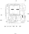
FIG. 2 is a schematic diagram of the assembly between a heat exchange component and a housing in the clothes dryer illustrated inFIG. 1 , and illustrates a flow direction of the air in an air cavity; and -
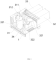
FIG. 3 is a schematic perspective view ofFIG. 2 ; - 1. housing; 11. air cavity; 12. blower impeller; 13. mesh filter; 14. blower cover; 2. tumbler;
- 3. heat exchange component; 31. compressor; 311. air discharge pipe; 312. air return pipe; 32. condenser; 321. condenser connection pipe; 322. throttle capillary; 33. evaporator; 331. evaporator connection pipe; 34. reversing valve.
- The present invention is described in detail in conjunction with the drawings. The drawings are simplified schematic diagrams, merely schematically illustrate a basic structure of the present invention, and thus only show the components related to the present invention.
- As shown in
FIG. 1 , the present invention provides a clothes dryer, including thehousing 1, and thetumbler 2 and theheat exchange component 3 installed in thehousing 1. Air in the clothes dryer circulates between thetumbler 2 and theheat exchange component 3 to dry clothes in thetumbler 2. - The
tumbler 2 is rotatably installed in thehousing 1. - As shown in
FIG. 2 , a bottom of thehousing 1 has theair cavity 11, theair cavity 11 is located below thetumbler 2, and theair cavity 11 and thetumbler 2 form a closed-loop air duct. Theblower impeller 12 located in theair cavity 11 is installed in thehousing 1, and theblower impeller 12 is used to drive the air in the closed-loop air duct to flow. Specifically, theblower impeller 12 is near to one end of theair cavity 11, and a motor is installed in thehousing 1 corresponding to theblower impeller 12 and is configured for driving theblower impeller 12 to rotate so as to drive the air to flow. The one end of theair cavity 11 near to theblower impeller 12 communicates with one end of thetumbler 2. As shown inFIG. 1 , for example, theblower cover 14 is installed at a back of thehousing 1, theblower cover 14 covers the one end of theair cavity 11 near to theblower impeller 12 and the one end of thetumbler 2, and the other end of thetumbler 2 communicates with the other end of theair cavity 11 such that theair cavity 11 and thetumbler 2 form the closed-loop air duct, and the air circulates between thetumbler 2 and theheat exchange component 3 under the driving of theblower impeller 12. - In a specific embodiment, the
mesh filter 13 located in theair cavity 11 is further installed in thehousing 1 and themesh filter 13 is located behind theevaporator 33. Themesh filter 13 is used to block impurities from entering thetumbler 2 and contaminating thetumbler 2, and does not function to filter the impurities for theevaporator 33 and thecondenser 32 in theheat exchange component 3. The mesh number of themesh filter 13 is not specifically required. In the present embodiment, themesh filter 13 is located between thecondenser 32 and theblower impeller 12. - As shown in
FIGS. 2 and3 , theheat exchange component 3 includes thecompressor 31, thecondenser 32, theevaporator 33 and the reversingvalve 34. - The
compressor 31 is fixedly installed on a bottom of thehousing 1. Thecompressor 31 has theair discharge pipe 311 and theair return pipe 312 thereon. Thecompressor 31 is used to compress the low temperature and low pressure working medium (such as a refrigerant) to a high temperature and high pressure state and then discharge it via theair discharge pipe 311. Theair return pipe 312 is configured for the working medium to flow into thecompressor 31. - The
condenser 32 and theevaporator 33 are accommodated in theair cavity 11, and thecondenser 32 and theevaporator 33 are distributed inside theair cavity 11 along a length direction of theair cavity 11. In particular, theevaporator 33 is located at a front end of the air duct of theair cavity 11 relative to thecondenser 32. - The
condenser 32 has thecondenser connection pipe 321 and thethrottle capillary 322 thereon. Thecondenser connection pipe 321 and thethrottle capillary 322 are respectively connected to both ends of an inner duct of thecondenser 32. Thethrottle capillary 322 communicates with thecondenser 32 and theevaporator 33. - The
evaporator 33 has theevaporator connection pipe 331 thereon. Theevaporator connection pipe 331 is connected to one end of an inner duct of theevaporator 33, and the other end of the inner duct of theevaporator 33 is connected to the other end of thethrottle capillary 322. Accordingly, the working medium can flow between thecondenser 32 and theevaporator 33 through thethrottle capillary 322. - In the present embodiment, the reversing
valve 34 is a four-way reversing valve, where one end of each of theair discharge pipe 311, theair return pipe 312, thecondenser connection pipe 321 and theevaporator connection pipe 331 is connected to the reversingvalve 34, thereby controlling the reversing valve to switch between two modes. Specifically, in a first mode, the working medium flows from theair discharge pipe 311 into thecondenser connection pipe 321 via the reversingvalve 34, the working medium in thecondenser 32 flows into theevaporator 33, and the working medium flows from theevaporator connection pipe 331 into theair return pipe 312 via the reversingvalve 34; in a second mode, the working medium can flow from theair discharge pipe 311 into theevaporator connection pipe 331 via the reversingvalve 34, the working medium in theevaporator 33 flows into thecondenser 32, and the working medium flows from thecondenser connection pipe 321 into theair return pipe 312 via the reversingvalve 34. - When the clothes dryer of the present invention runs normally, the reversing
valve 34 in theheat exchange component 3 is in the first mode. At the time, thecompressor 31 compresses the working medium from a low temperature and low pressure state to a high temperature and high pressure state, the high temperature and high pressure working medium passes through theair discharge pipe 311 and flows into thecondenser 32 via thecondenser connection pipe 321 so as to make thecondenser 32 in a high temperature state. The working medium is throttled by thethrottle capillary 322 after flowing through thecondenser 32 and becomes the low temperature and low pressure state, and then the low temperature and low pressure working medium enters theevaporator 33 so as to make theevaporator 33 in a low temperature state. The low temperature and low pressure working medium flows from theevaporator connection pipe 331 into theair return pipe 312 via the reversingvalve 34, the working medium returns to thecompressor 31 through theair return pipe 312, and theheat exchange component 3 completes the cycle. When theheat exchange component 3 is working, theblower impeller 12 is working at the same time to drive the air to directionally circulate between thetumbler 2 and theheat exchange component 3. Specifically, the air enters thetumbler 2 through theblower cover 14 after the air is heated up by thehigh temperature condenser 32, and then the hot air is in contact with the wet clothes in thetumbler 2 and then takes away water vapor. Subsequently, the moist air enters theair cavity 11 again and first contacts thelow temperature evaporator 33 such that the water vapor in the moist air contacts a surface of theevaporator 33 to be liquefied into liquid water, and then the liquid water drips off from theevaporator 33 and is collected. The dry air without moisture is heated up through thecondenser 32 and then enters thetumbler 2 again for drying. Such a cycle is repeated to complete the drying of the clothes. - When the clothes dryer is not in use, it switches to a cleaning mode. First, the reversing
valve 34 in theheat exchange component 3 is in the first mode, theblower impeller 12 stops rotating. The hot air does not circulate through theevaporator 33, the surface temperature of theevaporator 33 drops sharply such that the water vapor in the air condenses and frosts on the surface of theevaporator 33. After running for a period of time, the control program of the clothes dryer controls the reversingvalve 34 to the second mode. At the time, since the high temperature and high pressure working medium flows into theevaporator 33, theevaporator 33 is in the high temperature state to thaw the previous frost on the surface of theevaporator 33 into liquid water. The liquid water flows downward to drive the flocks attached to the surface of theevaporator 33 to fall off. After running for a period of time, theblower impeller 12 is started, so that the air circulates between thetumbler 2 and theair cavity 11 after the air is heated up through theevaporator 33. The hot air blows the flocks remaining on the surface of theevaporator 33 to further clean up the surface of theevaporator 33. Since the reversingvalve 34 was in the first mode previously, most of water vapor inside the clothes dryer has been liquefied and collected, the humidity of the clothes dryer is relatively low. At the time, it is not easy to generate a large amount of condensed water on the surface of thecondenser 32. Furthermore, thecondenser 32 is located behind thehigh temperature evaporator 33, so that the circulated hot air will continuously dry theevaporator 33 and thecondenser 32, and the flocks remaining on theevaporator 33 is filtered by themesh filter 13, which is not easily attached to thecondenser 32 after the flocks are blown off. Thus, the surface of thecondenser 32 is also cleaned up. - Therefore, the clothes dryer of the present invention at least has the following advantageous effects.
- In the clothes dryer of the present invention, the
heat exchange component 3 further includes the reversingvalve 34, and the reversingvalve 34 can switch between two modes. In a first mode, the working medium flows from thecompressor 31 to thecondenser 32 via the reversingvalve 34, the working medium in thecondenser 32 flows into theevaporator 33, and the working medium in theevaporator 33 flows back to thecompressor 31 via the reversingvalve 34. In a second mode, the working medium flows from thecompressor 31 to theevaporator 33 via the reversingvalve 34, the working medium in theevaporator 33 flows into thecondenser 32, and the working medium in thecondenser 32 flows back to thecompressor 31 via the reversingvalve 34. When it needs to be cleaned up, first the reversingvalve 34 in theheat exchange component 3 switches to the first mode and theblower impeller 12 is controlled to stop rotating, so that the high temperature and high pressure working medium that enters thecondenser 32 is converted to the low temperature and low pressure working medium by thethrottle capillary 322 and then enters theevaporator 33 to decrease the temperature of theevaporator 33 such that water vapor in the air condenses and frosts on a surface of theevaporator 33. After running for a period of time, a control program controls the reversingvalve 34 to switch to the second mode. At the time, the high temperature and high pressure working medium flows into theevaporator 33 via the reversingvalve 34 and theevaporator 33 is in a high temperature state so as to thaw the previous frost on the surface of theevaporator 33 into liquid water. The liquid water flows downward to drive the flocks attached to the surface of theevaporator 33 to fall off. After running for a period of time, theblower impeller 12 is started in order to circulate the air between thetumbler 2 and theair cavity 11 after the air is heated up through theevaporator 33. The hot air blows the flocks remaining on the surface of theevaporator 33 to clean the surface of theevaporator 33 more thoroughly, thereby implementing self-cleaning. At the same time, theevaporator 33 does not need to be protected by the blocking effect of the mesh filter, and the working performance of the clothes dryer is not affected. - Taking the above-mentioned ideal embodiment according to the present invention as inspiration, through the above description content, the person in the art can make various changes and modifications without departing from the scope of the present invention. The technical scope of the present invention is not limited to the content of the description, and the technical scope thereof must be determined according to the scope of the claims.
Claims (10)
- A clothes dryer, comprising a housing (1), a tumbler (2) and a heat exchange (3) component, whereinthe housing (1) has an air cavity (11) therein,the air cavity (11) and the tumbler (2) form a closed-loop air duct,a blower impeller (12) for driving air in the closed-loop air duct to flow is provided in the housing (1),the heat exchange (3) component comprises a compressor (31), and a condenser (32) and an evaporator (33), whereinthe condenser (32) and the evaporator (33) are placed inside the air cavity (11),the compressor (31) is used to compress a working medium into a high temperature and high pressure state, andthe condenser (32) communicates with the evaporator (33) through a throttle capillary (322),the heat exchange (3) component further comprises a reversing valve (34), whereinthe reversing valve (34) is configured to switch between a first mode and a second mode through a remote control program,in the first mode, the working medium flows from the compressor (31) to the condenser (32) via the reversing valve (34), the working medium in the condenser (32) flows into the evaporator (33), and the working medium in the evaporator (33) flows back to the compressor (31) via the reversing valve (34), andin the second mode, the working medium flows from the compressor (31) to the evaporator (33) via the reversing valve (34), the working medium in the evaporator (33) flows into the condenser (32), and the working medium in the condenser (32) flows back to the compressor (31) via the reversing valve (34) and characterized in thatthe clothes dryer has a cleaning mode being configured to switch the reversing valve (34) to the first mode and to stop rotating the blower impeller (12) such that the water vapor in the air condenses and frosts on the surface of the evaporator (33), wherein the cleaning mode is further configured to, after running for a period of time, to control the reversing valve (34) to switch to second mode using the control program to thaw the previous frost on the surface of the evaporator (33) into liquid water.
- The clothes dryer of claim 1, wherein the blower impeller (12) is installed in the air cavity (11), the blower impeller (12) is near to a first end of the air cavity (11), and a motor for driving the blower impeller (12) to rotate is installed in the housing (1) corresponding to the blower impeller (12).
- The clothes dryer of claim 1, wherein a blower cover (14) is installed at a back of the housing (1), the blower cover (14) covers a first end of the air cavity (11) near to the blower impeller (12) and a first end of the tumbler (2), and a second end of the tumbler (2) communicates with a second end of the air cavity (11).
- The clothes dryer of claim 1, wherein the housing (1) is further provided with a mesh filter (13) located in the air cavity (11) therein.
- The clothes dryer of claim 1, wherein the compressor (31) is fixedly installed on a bottom of the housing (1), and the compressor (31) comprises an air discharge pipe (311) for discharging the working medium and an air return pipe (312) for backflow of the working medium.
- The clothes dryer of claim 1, wherein the evaporator (33) is located at a front end of the closed-loop air duct of the air cavity (11) relative to the condenser (32).
- The clothes dryer of claim 5, wherein the condenser (32) is further provided with a condenser connection pipe (321), and the condenser connection pipe (321) and a first end of the throttle capillary (322) are connected to both ends of an inner duct of the condenser (32), respectively.
- The clothes dryer of claim 7, wherein the evaporator (33) has an evaporator connection pipe (331), the evaporator connection pipe (331) is connected to a first end of an inner duct of the evaporator (33), and a second end of the inner duct of the evaporator (33) is connected to a second end of the throttle capillary (322).
- The clothes dryer of claim 8, wherein the reversing valve (34) is a four-way reversing valve (34).
- The clothes dryer of claim 9, wherein one end of each of the air discharge pipe (311), the air return pipe (312), the condenser connection pipe (321) and the evaporator connection pipe (331) is connected to the four-way reversing valve (34).
Applications Claiming Priority (1)
| Application Number | Priority Date | Filing Date | Title |
|---|---|---|---|
| CN202110357170.5A CN113106713A (en) | 2021-04-01 | 2021-04-01 | Clothes dryer |
Publications (2)
| Publication Number | Publication Date |
|---|---|
| EP4067557A1 EP4067557A1 (en) | 2022-10-05 |
| EP4067557B1 true EP4067557B1 (en) | 2023-06-28 |
Family
ID=76713799
Family Applications (1)
| Application Number | Title | Priority Date | Filing Date |
|---|---|---|---|
| EP21188353.3A Active EP4067557B1 (en) | 2021-04-01 | 2021-07-28 | Clothes dryer |
Country Status (5)
| Country | Link |
|---|---|
| US (1) | US12180643B2 (en) |
| EP (1) | EP4067557B1 (en) |
| JP (1) | JP2022158804A (en) |
| KR (1) | KR20220136868A (en) |
| CN (1) | CN113106713A (en) |
Families Citing this family (1)
| Publication number | Priority date | Publication date | Assignee | Title |
|---|---|---|---|---|
| EP4086382B1 (en) * | 2019-12-30 | 2024-10-16 | Qingdao Haier Washing Machine Co., Ltd. | Clothes drying device |
Family Cites Families (27)
| Publication number | Priority date | Publication date | Assignee | Title |
|---|---|---|---|---|
| CN2357034Y (en) * | 1998-11-06 | 2000-01-05 | 中山威力集团公司 | Internal circulation environment-friendly clothes dryer |
| JP4531414B2 (en) | 2004-02-16 | 2010-08-25 | パナソニック株式会社 | Washing and drying machine |
| JP4856015B2 (en) * | 2007-06-29 | 2012-01-18 | シャープ株式会社 | Air conditioner |
| DE102007060851A1 (en) * | 2007-12-18 | 2009-06-25 | BSH Bosch und Siemens Hausgeräte GmbH | Household appliance for the care of laundry items and method for removing lint |
| JP2009195362A (en) * | 2008-02-20 | 2009-09-03 | Panasonic Corp | Clothes dryer |
| US8393172B2 (en) * | 2008-09-30 | 2013-03-12 | Sanyo Electric Co., Ltd. | Heat pump drying machine |
| JP2011115432A (en) * | 2009-12-04 | 2011-06-16 | Panasonic Corp | Clothes dryer |
| ITTO20101022A1 (en) | 2010-12-20 | 2012-06-21 | Indesit Co Spa | MACHINE FOR DRYING OF LINEN FOR HOME USE |
| CN102206916B (en) * | 2011-06-23 | 2016-08-31 | 青岛海尔洗衣机有限公司 | A kind of heat pump drying system for cylinder drying and control method |
| CN102677439B (en) * | 2012-04-27 | 2016-12-14 | 青岛海尔滚筒洗衣机有限公司 | A kind of control method removing heat pump clothes dryer evaporimeter frosting and heat pump clothes dryer |
| CN104233735B (en) * | 2013-06-21 | 2018-02-23 | 海尔集团公司 | A kind of heat pump clothes dryer and clothes-drying method |
| JP2016104111A (en) * | 2014-11-19 | 2016-06-09 | 三星電子株式会社Samsung Electronics Co.,Ltd. | Dryer |
| CN106498682A (en) * | 2015-09-06 | 2017-03-15 | 无锡小天鹅股份有限公司 | Heat pump clothes dryer and its control method |
| EP3196569A1 (en) * | 2016-01-21 | 2017-07-26 | Vaillant GmbH | Sensor arramgement in a heat pump system |
| CN107435228B (en) * | 2016-05-27 | 2019-10-18 | 浙江三花智能控制股份有限公司 | clothes dryer |
| CN106352417A (en) * | 2016-10-26 | 2017-01-25 | 广东美的制冷设备有限公司 | Heat accumulation and defrosting air-conditioning system and control method thereof |
| CN106679067A (en) * | 2016-11-11 | 2017-05-17 | 青岛海尔空调器有限总公司 | Self-cleaning method for air conditioner heat exchanger |
| JP6340111B1 (en) * | 2017-04-28 | 2018-06-06 | 日立ジョンソンコントロールズ空調株式会社 | Air conditioner indoor unit |
| CN108362028A (en) * | 2018-02-07 | 2018-08-03 | 乐易泰(宁波)热能设备有限公司 | A kind of control system for heat pump |
| JP2018102992A (en) * | 2018-04-03 | 2018-07-05 | 日立ジョンソンコントロールズ空調株式会社 | Refrigeration cycle equipment |
| CN110735304B (en) * | 2018-07-19 | 2022-11-15 | 青岛海尔洗涤电器有限公司 | Thread scrap cleaning method for heat pump clothes dryer and heat pump clothes dryer |
| DE102019202284A1 (en) * | 2019-02-20 | 2020-08-20 | BSH Hausgeräte GmbH | Household electrical appliance |
| CN209923620U (en) * | 2019-04-16 | 2020-01-10 | 珠海格力电器股份有限公司 | Heat pump type washing and drying integrated machine and evaporator cleaning device thereof |
| CN109914065B (en) * | 2019-04-16 | 2023-08-15 | 珠海格力电器股份有限公司 | Heat pump washing and drying machine, its evaporator cleaning method and device |
| CN111851023B (en) * | 2019-04-29 | 2022-11-29 | 宁波吉德电器有限公司 | Self-cleaning method for clothes dryer and clothes dryer |
| CN210425617U (en) * | 2019-08-07 | 2020-04-28 | 广东欧科空调制冷有限公司 | Air-cooled screw air conditioner and four-way valve thereof |
| CN212426487U (en) * | 2020-01-08 | 2021-01-29 | 江苏科菱库精工科技有限公司 | Mould-proof heat pump clothes dryer |
-
2021
- 2021-04-01 CN CN202110357170.5A patent/CN113106713A/en active Pending
- 2021-07-23 KR KR1020210097354A patent/KR20220136868A/en not_active Ceased
- 2021-07-23 US US17/383,466 patent/US12180643B2/en active Active
- 2021-07-28 EP EP21188353.3A patent/EP4067557B1/en active Active
- 2021-07-30 JP JP2021125306A patent/JP2022158804A/en active Pending
Also Published As
| Publication number | Publication date |
|---|---|
| EP4067557A1 (en) | 2022-10-05 |
| KR20220136868A (en) | 2022-10-11 |
| CN113106713A (en) | 2021-07-13 |
| US12180643B2 (en) | 2024-12-31 |
| US20220316129A1 (en) | 2022-10-06 |
| JP2022158804A (en) | 2022-10-17 |
Similar Documents
| Publication | Publication Date | Title |
|---|---|---|
| CN101310068B (en) | Clothes dryer | |
| JP5256960B2 (en) | Article washing and drying equipment | |
| CN102206916B (en) | A kind of heat pump drying system for cylinder drying and control method | |
| JPH0722632B2 (en) | Dryer | |
| JP2018102992A (en) | Refrigeration cycle equipment | |
| JP7173719B2 (en) | clothes dryer | |
| JP2009195362A (en) | Clothes dryer | |
| JP2007319458A (en) | Washing and drying machine | |
| JP6321870B2 (en) | Refrigeration cycle equipment | |
| US12180643B2 (en) | Clothes dryer | |
| JP2008301940A (en) | Clothes dryer | |
| CN1833150A (en) | Method of operation of a device with at least one subroutine step "drying" | |
| CN108570837B (en) | A heat pump dryer with washable heat exchanger | |
| JP2012245316A (en) | Washing and drying machine and method of drying washing and drying machine | |
| DE19731826A1 (en) | Laundry dryer for sensitive fabrics | |
| JP2020014745A (en) | Washing and drying machine | |
| JP6518498B2 (en) | Washing and drying machine | |
| JP7488035B2 (en) | Clothes dryer | |
| CN112030497B (en) | A heat pump clothes dryer and its control method | |
| JP2014113190A (en) | Washing and drying machine | |
| CN103590224A (en) | Clothes processing device and working method thereof | |
| CN108486838B (en) | Heat pump type clothes dryer capable of blowing and washing heat exchanger | |
| JP2024003308A (en) | Washing and drying machine | |
| EP3853404B1 (en) | A laundry dryer | |
| CN101135101A (en) | A washing machine plugged with a dehumidifier as a washing machine drying device |
Legal Events
| Date | Code | Title | Description |
|---|---|---|---|
| PUAI | Public reference made under article 153(3) epc to a published international application that has entered the european phase |
Free format text: ORIGINAL CODE: 0009012 |
|
| STAA | Information on the status of an ep patent application or granted ep patent |
Free format text: STATUS: REQUEST FOR EXAMINATION WAS MADE |
|
| 17P | Request for examination filed |
Effective date: 20210728 |
|
| AK | Designated contracting states |
Kind code of ref document: A1 Designated state(s): AL AT BE BG CH CY CZ DE DK EE ES FI FR GB GR HR HU IE IS IT LI LT LU LV MC MK MT NL NO PL PT RO RS SE SI SK SM TR |
|
| RIC1 | Information provided on ipc code assigned before grant |
Ipc: D06F 58/22 20060101ALN20230201BHEP Ipc: D06F 58/02 20060101ALN20230201BHEP Ipc: F25B 47/02 20060101ALI20230201BHEP Ipc: F25B 13/00 20060101ALI20230201BHEP Ipc: D06F 58/24 20060101ALI20230201BHEP Ipc: D06F 58/20 20060101AFI20230201BHEP |
|
| GRAP | Despatch of communication of intention to grant a patent |
Free format text: ORIGINAL CODE: EPIDOSNIGR1 |
|
| STAA | Information on the status of an ep patent application or granted ep patent |
Free format text: STATUS: GRANT OF PATENT IS INTENDED |
|
| RIC1 | Information provided on ipc code assigned before grant |
Ipc: D06F 58/22 20060101ALN20230213BHEP Ipc: D06F 58/02 20060101ALN20230213BHEP Ipc: F25B 47/02 20060101ALI20230213BHEP Ipc: F25B 13/00 20060101ALI20230213BHEP Ipc: D06F 58/24 20060101ALI20230213BHEP Ipc: D06F 58/20 20060101AFI20230213BHEP |
|
| INTG | Intention to grant announced |
Effective date: 20230313 |
|
| GRAS | Grant fee paid |
Free format text: ORIGINAL CODE: EPIDOSNIGR3 |
|
| GRAA | (expected) grant |
Free format text: ORIGINAL CODE: 0009210 |
|
| STAA | Information on the status of an ep patent application or granted ep patent |
Free format text: STATUS: THE PATENT HAS BEEN GRANTED |
|
| AK | Designated contracting states |
Kind code of ref document: B1 Designated state(s): AL AT BE BG CH CY CZ DE DK EE ES FI FR GB GR HR HU IE IS IT LI LT LU LV MC MK MT NL NO PL PT RO RS SE SI SK SM TR |
|
| REG | Reference to a national code |
Ref country code: CH Ref legal event code: EP |
|
| REG | Reference to a national code |
Ref country code: AT Ref legal event code: REF Ref document number: 1582787 Country of ref document: AT Kind code of ref document: T Effective date: 20230715 |
|
| REG | Reference to a national code |
Ref country code: IE Ref legal event code: FG4D |
|
| REG | Reference to a national code |
Ref country code: DE Ref legal event code: R096 Ref document number: 602021003124 Country of ref document: DE |
|
| REG | Reference to a national code |
Ref country code: LT Ref legal event code: MG9D |
|
| PG25 | Lapsed in a contracting state [announced via postgrant information from national office to epo] |
Ref country code: SE Free format text: LAPSE BECAUSE OF FAILURE TO SUBMIT A TRANSLATION OF THE DESCRIPTION OR TO PAY THE FEE WITHIN THE PRESCRIBED TIME-LIMIT Effective date: 20230628 Ref country code: NO Free format text: LAPSE BECAUSE OF FAILURE TO SUBMIT A TRANSLATION OF THE DESCRIPTION OR TO PAY THE FEE WITHIN THE PRESCRIBED TIME-LIMIT Effective date: 20230928 |
|
| REG | Reference to a national code |
Ref country code: NL Ref legal event code: MP Effective date: 20230628 |
|
| REG | Reference to a national code |
Ref country code: AT Ref legal event code: MK05 Ref document number: 1582787 Country of ref document: AT Kind code of ref document: T Effective date: 20230628 |
|
| PG25 | Lapsed in a contracting state [announced via postgrant information from national office to epo] |
Ref country code: RS Free format text: LAPSE BECAUSE OF FAILURE TO SUBMIT A TRANSLATION OF THE DESCRIPTION OR TO PAY THE FEE WITHIN THE PRESCRIBED TIME-LIMIT Effective date: 20230628 Ref country code: NL Free format text: LAPSE BECAUSE OF FAILURE TO SUBMIT A TRANSLATION OF THE DESCRIPTION OR TO PAY THE FEE WITHIN THE PRESCRIBED TIME-LIMIT Effective date: 20230628 Ref country code: LV Free format text: LAPSE BECAUSE OF FAILURE TO SUBMIT A TRANSLATION OF THE DESCRIPTION OR TO PAY THE FEE WITHIN THE PRESCRIBED TIME-LIMIT Effective date: 20230628 Ref country code: LT Free format text: LAPSE BECAUSE OF FAILURE TO SUBMIT A TRANSLATION OF THE DESCRIPTION OR TO PAY THE FEE WITHIN THE PRESCRIBED TIME-LIMIT Effective date: 20230628 Ref country code: HR Free format text: LAPSE BECAUSE OF FAILURE TO SUBMIT A TRANSLATION OF THE DESCRIPTION OR TO PAY THE FEE WITHIN THE PRESCRIBED TIME-LIMIT Effective date: 20230628 Ref country code: GR Free format text: LAPSE BECAUSE OF FAILURE TO SUBMIT A TRANSLATION OF THE DESCRIPTION OR TO PAY THE FEE WITHIN THE PRESCRIBED TIME-LIMIT Effective date: 20230929 |
|
| PG25 | Lapsed in a contracting state [announced via postgrant information from national office to epo] |
Ref country code: FI Free format text: LAPSE BECAUSE OF FAILURE TO SUBMIT A TRANSLATION OF THE DESCRIPTION OR TO PAY THE FEE WITHIN THE PRESCRIBED TIME-LIMIT Effective date: 20230628 |
|
| PG25 | Lapsed in a contracting state [announced via postgrant information from national office to epo] |
Ref country code: SK Free format text: LAPSE BECAUSE OF FAILURE TO SUBMIT A TRANSLATION OF THE DESCRIPTION OR TO PAY THE FEE WITHIN THE PRESCRIBED TIME-LIMIT Effective date: 20230628 |
|
| PG25 | Lapsed in a contracting state [announced via postgrant information from national office to epo] |
Ref country code: ES Free format text: LAPSE BECAUSE OF FAILURE TO SUBMIT A TRANSLATION OF THE DESCRIPTION OR TO PAY THE FEE WITHIN THE PRESCRIBED TIME-LIMIT Effective date: 20230628 |
|
| PG25 | Lapsed in a contracting state [announced via postgrant information from national office to epo] |
Ref country code: IS Free format text: LAPSE BECAUSE OF FAILURE TO SUBMIT A TRANSLATION OF THE DESCRIPTION OR TO PAY THE FEE WITHIN THE PRESCRIBED TIME-LIMIT Effective date: 20231028 |
|
| PG25 | Lapsed in a contracting state [announced via postgrant information from national office to epo] |
Ref country code: SM Free format text: LAPSE BECAUSE OF FAILURE TO SUBMIT A TRANSLATION OF THE DESCRIPTION OR TO PAY THE FEE WITHIN THE PRESCRIBED TIME-LIMIT Effective date: 20230628 Ref country code: SK Free format text: LAPSE BECAUSE OF FAILURE TO SUBMIT A TRANSLATION OF THE DESCRIPTION OR TO PAY THE FEE WITHIN THE PRESCRIBED TIME-LIMIT Effective date: 20230628 Ref country code: RO Free format text: LAPSE BECAUSE OF FAILURE TO SUBMIT A TRANSLATION OF THE DESCRIPTION OR TO PAY THE FEE WITHIN THE PRESCRIBED TIME-LIMIT Effective date: 20230628 Ref country code: PT Free format text: LAPSE BECAUSE OF FAILURE TO SUBMIT A TRANSLATION OF THE DESCRIPTION OR TO PAY THE FEE WITHIN THE PRESCRIBED TIME-LIMIT Effective date: 20231030 Ref country code: IS Free format text: LAPSE BECAUSE OF FAILURE TO SUBMIT A TRANSLATION OF THE DESCRIPTION OR TO PAY THE FEE WITHIN THE PRESCRIBED TIME-LIMIT Effective date: 20231028 Ref country code: ES Free format text: LAPSE BECAUSE OF FAILURE TO SUBMIT A TRANSLATION OF THE DESCRIPTION OR TO PAY THE FEE WITHIN THE PRESCRIBED TIME-LIMIT Effective date: 20230628 Ref country code: EE Free format text: LAPSE BECAUSE OF FAILURE TO SUBMIT A TRANSLATION OF THE DESCRIPTION OR TO PAY THE FEE WITHIN THE PRESCRIBED TIME-LIMIT Effective date: 20230628 Ref country code: CZ Free format text: LAPSE BECAUSE OF FAILURE TO SUBMIT A TRANSLATION OF THE DESCRIPTION OR TO PAY THE FEE WITHIN THE PRESCRIBED TIME-LIMIT Effective date: 20230628 Ref country code: AT Free format text: LAPSE BECAUSE OF FAILURE TO SUBMIT A TRANSLATION OF THE DESCRIPTION OR TO PAY THE FEE WITHIN THE PRESCRIBED TIME-LIMIT Effective date: 20230628 |
|
| PG25 | Lapsed in a contracting state [announced via postgrant information from national office to epo] |
Ref country code: PL Free format text: LAPSE BECAUSE OF FAILURE TO SUBMIT A TRANSLATION OF THE DESCRIPTION OR TO PAY THE FEE WITHIN THE PRESCRIBED TIME-LIMIT Effective date: 20230628 |
|
| PG25 | Lapsed in a contracting state [announced via postgrant information from national office to epo] |
Ref country code: MC Free format text: LAPSE BECAUSE OF FAILURE TO SUBMIT A TRANSLATION OF THE DESCRIPTION OR TO PAY THE FEE WITHIN THE PRESCRIBED TIME-LIMIT Effective date: 20230628 |
|
| REG | Reference to a national code |
Ref country code: BE Ref legal event code: MM Effective date: 20230731 |
|
| PG25 | Lapsed in a contracting state [announced via postgrant information from national office to epo] |
Ref country code: LU Free format text: LAPSE BECAUSE OF NON-PAYMENT OF DUE FEES Effective date: 20230728 |
|
| PG25 | Lapsed in a contracting state [announced via postgrant information from national office to epo] |
Ref country code: MC Free format text: LAPSE BECAUSE OF FAILURE TO SUBMIT A TRANSLATION OF THE DESCRIPTION OR TO PAY THE FEE WITHIN THE PRESCRIBED TIME-LIMIT Effective date: 20230628 Ref country code: LU Free format text: LAPSE BECAUSE OF NON-PAYMENT OF DUE FEES Effective date: 20230728 |
|
| REG | Reference to a national code |
Ref country code: DE Ref legal event code: R097 Ref document number: 602021003124 Country of ref document: DE |
|
| REG | Reference to a national code |
Ref country code: IE Ref legal event code: MM4A |
|
| PG25 | Lapsed in a contracting state [announced via postgrant information from national office to epo] |
Ref country code: DK Free format text: LAPSE BECAUSE OF FAILURE TO SUBMIT A TRANSLATION OF THE DESCRIPTION OR TO PAY THE FEE WITHIN THE PRESCRIBED TIME-LIMIT Effective date: 20230628 |
|
| PLBE | No opposition filed within time limit |
Free format text: ORIGINAL CODE: 0009261 |
|
| STAA | Information on the status of an ep patent application or granted ep patent |
Free format text: STATUS: NO OPPOSITION FILED WITHIN TIME LIMIT |
|
| PG25 | Lapsed in a contracting state [announced via postgrant information from national office to epo] |
Ref country code: IT Free format text: LAPSE BECAUSE OF FAILURE TO SUBMIT A TRANSLATION OF THE DESCRIPTION OR TO PAY THE FEE WITHIN THE PRESCRIBED TIME-LIMIT Effective date: 20230628 Ref country code: BE Free format text: LAPSE BECAUSE OF NON-PAYMENT OF DUE FEES Effective date: 20230731 |
|
| 26N | No opposition filed |
Effective date: 20240402 |
|
| PG25 | Lapsed in a contracting state [announced via postgrant information from national office to epo] |
Ref country code: IE Free format text: LAPSE BECAUSE OF NON-PAYMENT OF DUE FEES Effective date: 20230728 |
|
| PG25 | Lapsed in a contracting state [announced via postgrant information from national office to epo] |
Ref country code: IE Free format text: LAPSE BECAUSE OF NON-PAYMENT OF DUE FEES Effective date: 20230728 Ref country code: FR Free format text: LAPSE BECAUSE OF NON-PAYMENT OF DUE FEES Effective date: 20230828 Ref country code: SI Free format text: LAPSE BECAUSE OF FAILURE TO SUBMIT A TRANSLATION OF THE DESCRIPTION OR TO PAY THE FEE WITHIN THE PRESCRIBED TIME-LIMIT Effective date: 20230628 |
|
| PGFP | Annual fee paid to national office [announced via postgrant information from national office to epo] |
Ref country code: DE Payment date: 20240724 Year of fee payment: 4 |
|
| PG25 | Lapsed in a contracting state [announced via postgrant information from national office to epo] |
Ref country code: BG Free format text: LAPSE BECAUSE OF FAILURE TO SUBMIT A TRANSLATION OF THE DESCRIPTION OR TO PAY THE FEE WITHIN THE PRESCRIBED TIME-LIMIT Effective date: 20230628 |
|
| PG25 | Lapsed in a contracting state [announced via postgrant information from national office to epo] |
Ref country code: BG Free format text: LAPSE BECAUSE OF FAILURE TO SUBMIT A TRANSLATION OF THE DESCRIPTION OR TO PAY THE FEE WITHIN THE PRESCRIBED TIME-LIMIT Effective date: 20230628 |
|
| REG | Reference to a national code |
Ref country code: CH Ref legal event code: PL |
|
| PG25 | Lapsed in a contracting state [announced via postgrant information from national office to epo] |
Ref country code: CH Free format text: LAPSE BECAUSE OF NON-PAYMENT OF DUE FEES Effective date: 20240731 |
|
| PG25 | Lapsed in a contracting state [announced via postgrant information from national office to epo] |
Ref country code: CY Free format text: LAPSE BECAUSE OF FAILURE TO SUBMIT A TRANSLATION OF THE DESCRIPTION OR TO PAY THE FEE WITHIN THE PRESCRIBED TIME-LIMIT; INVALID AB INITIO Effective date: 20210728 |
|
| PG25 | Lapsed in a contracting state [announced via postgrant information from national office to epo] |
Ref country code: HU Free format text: LAPSE BECAUSE OF FAILURE TO SUBMIT A TRANSLATION OF THE DESCRIPTION OR TO PAY THE FEE WITHIN THE PRESCRIBED TIME-LIMIT; INVALID AB INITIO Effective date: 20210728 |
|
| PG25 | Lapsed in a contracting state [announced via postgrant information from national office to epo] |
Ref country code: TR Free format text: LAPSE BECAUSE OF FAILURE TO SUBMIT A TRANSLATION OF THE DESCRIPTION OR TO PAY THE FEE WITHIN THE PRESCRIBED TIME-LIMIT Effective date: 20230628 |
|
| REG | Reference to a national code |
Ref country code: DE Ref legal event code: R119 Ref document number: 602021003124 Country of ref document: DE |
|
| GBPC | Gb: european patent ceased through non-payment of renewal fee |
Effective date: 20250728 |
|
| PG25 | Lapsed in a contracting state [announced via postgrant information from national office to epo] |
Ref country code: GB Free format text: LAPSE BECAUSE OF NON-PAYMENT OF DUE FEES Effective date: 20250728 |
|
| PG25 | Lapsed in a contracting state [announced via postgrant information from national office to epo] |
Ref country code: DE Free format text: LAPSE BECAUSE OF NON-PAYMENT OF DUE FEES Effective date: 20260203 |