EP4067236B1 - Elektrisches antriebssystem für ein luftfahrzeug - Google Patents
Elektrisches antriebssystem für ein luftfahrzeug Download PDFInfo
- Publication number
- EP4067236B1 EP4067236B1 EP22162027.1A EP22162027A EP4067236B1 EP 4067236 B1 EP4067236 B1 EP 4067236B1 EP 22162027 A EP22162027 A EP 22162027A EP 4067236 B1 EP4067236 B1 EP 4067236B1
- Authority
- EP
- European Patent Office
- Prior art keywords
- nacelle
- circulation channel
- air circulation
- propulsion system
- air
- Prior art date
- Legal status (The legal status is an assumption and is not a legal conclusion. Google has not performed a legal analysis and makes no representation as to the accuracy of the status listed.)
- Active
Links
Images


Classifications
-
- B—PERFORMING OPERATIONS; TRANSPORTING
- B64—AIRCRAFT; AVIATION; COSMONAUTICS
- B64D—EQUIPMENT FOR FITTING IN OR TO AIRCRAFT; FLIGHT SUITS; PARACHUTES; ARRANGEMENT OR MOUNTING OF POWER PLANTS OR PROPULSION TRANSMISSIONS IN AIRCRAFT
- B64D29/00—Power-plant nacelles, fairings or cowlings
-
- B—PERFORMING OPERATIONS; TRANSPORTING
- B60—VEHICLES IN GENERAL
- B60L—PROPULSION OF ELECTRICALLY-PROPELLED VEHICLES; SUPPLYING ELECTRIC POWER FOR AUXILIARY EQUIPMENT OF ELECTRICALLY-PROPELLED VEHICLES; ELECTRODYNAMIC BRAKE SYSTEMS FOR VEHICLES IN GENERAL; MAGNETIC SUSPENSION OR LEVITATION FOR VEHICLES; MONITORING OPERATING VARIABLES OF ELECTRICALLY-PROPELLED VEHICLES; ELECTRIC SAFETY DEVICES FOR ELECTRICALLY-PROPELLED VEHICLES
- B60L50/00—Electric propulsion with power supplied within the vehicle
- B60L50/50—Electric propulsion with power supplied within the vehicle using propulsion power supplied by batteries or fuel cells
- B60L50/70—Electric propulsion with power supplied within the vehicle using propulsion power supplied by batteries or fuel cells using power supplied by fuel cells
-
- B—PERFORMING OPERATIONS; TRANSPORTING
- B60—VEHICLES IN GENERAL
- B60L—PROPULSION OF ELECTRICALLY-PROPELLED VEHICLES; SUPPLYING ELECTRIC POWER FOR AUXILIARY EQUIPMENT OF ELECTRICALLY-PROPELLED VEHICLES; ELECTRODYNAMIC BRAKE SYSTEMS FOR VEHICLES IN GENERAL; MAGNETIC SUSPENSION OR LEVITATION FOR VEHICLES; MONITORING OPERATING VARIABLES OF ELECTRICALLY-PROPELLED VEHICLES; ELECTRIC SAFETY DEVICES FOR ELECTRICALLY-PROPELLED VEHICLES
- B60L58/00—Methods or circuit arrangements for monitoring or controlling batteries or fuel cells, specially adapted for electric vehicles
- B60L58/30—Methods or circuit arrangements for monitoring or controlling batteries or fuel cells, specially adapted for electric vehicles for monitoring or controlling fuel cells
- B60L58/32—Methods or circuit arrangements for monitoring or controlling batteries or fuel cells, specially adapted for electric vehicles for monitoring or controlling fuel cells for controlling the temperature of fuel cells, e.g. by controlling the electric load
- B60L58/33—Methods or circuit arrangements for monitoring or controlling batteries or fuel cells, specially adapted for electric vehicles for monitoring or controlling fuel cells for controlling the temperature of fuel cells, e.g. by controlling the electric load by cooling
-
- B—PERFORMING OPERATIONS; TRANSPORTING
- B64—AIRCRAFT; AVIATION; COSMONAUTICS
- B64C—AEROPLANES; HELICOPTERS
- B64C11/00—Propellers, e.g. of ducted type; Features common to propellers and rotors for rotorcraft
-
- B—PERFORMING OPERATIONS; TRANSPORTING
- B64—AIRCRAFT; AVIATION; COSMONAUTICS
- B64D—EQUIPMENT FOR FITTING IN OR TO AIRCRAFT; FLIGHT SUITS; PARACHUTES; ARRANGEMENT OR MOUNTING OF POWER PLANTS OR PROPULSION TRANSMISSIONS IN AIRCRAFT
- B64D27/00—Arrangement or mounting of power plants in aircraft; Aircraft characterised by the type or position of power plants
- B64D27/02—Aircraft characterised by the type or position of power plants
- B64D27/30—Aircraft characterised by electric power plants
- B64D27/34—All-electric aircraft
-
- B—PERFORMING OPERATIONS; TRANSPORTING
- B64—AIRCRAFT; AVIATION; COSMONAUTICS
- B64D—EQUIPMENT FOR FITTING IN OR TO AIRCRAFT; FLIGHT SUITS; PARACHUTES; ARRANGEMENT OR MOUNTING OF POWER PLANTS OR PROPULSION TRANSMISSIONS IN AIRCRAFT
- B64D27/00—Arrangement or mounting of power plants in aircraft; Aircraft characterised by the type or position of power plants
- B64D27/02—Aircraft characterised by the type or position of power plants
- B64D27/30—Aircraft characterised by electric power plants
- B64D27/35—Arrangements for on-board electric energy production, distribution, recovery or storage
- B64D27/355—Arrangements for on-board electric energy production, distribution, recovery or storage using fuel cells
-
- B—PERFORMING OPERATIONS; TRANSPORTING
- B64—AIRCRAFT; AVIATION; COSMONAUTICS
- B64D—EQUIPMENT FOR FITTING IN OR TO AIRCRAFT; FLIGHT SUITS; PARACHUTES; ARRANGEMENT OR MOUNTING OF POWER PLANTS OR PROPULSION TRANSMISSIONS IN AIRCRAFT
- B64D33/00—Arrangement in aircraft of power plant parts or auxiliaries not otherwise provided for
- B64D33/08—Arrangement in aircraft of power plant parts or auxiliaries not otherwise provided for of power plant cooling systems
-
- B—PERFORMING OPERATIONS; TRANSPORTING
- B64—AIRCRAFT; AVIATION; COSMONAUTICS
- B64D—EQUIPMENT FOR FITTING IN OR TO AIRCRAFT; FLIGHT SUITS; PARACHUTES; ARRANGEMENT OR MOUNTING OF POWER PLANTS OR PROPULSION TRANSMISSIONS IN AIRCRAFT
- B64D35/00—Transmitting power from power plants to propellers or rotors; Arrangements of transmissions
- B64D35/02—Transmitting power from power plants to propellers or rotors; Arrangements of transmissions specially adapted for specific power plants
- B64D35/021—Transmitting power from power plants to propellers or rotors; Arrangements of transmissions specially adapted for specific power plants for electric power plants
- B64D35/026—Transmitting power from power plants to propellers or rotors; Arrangements of transmissions specially adapted for specific power plants for electric power plants the electric power plant being integral with the propeller or rotor
-
- F—MECHANICAL ENGINEERING; LIGHTING; HEATING; WEAPONS; BLASTING
- F02—COMBUSTION ENGINES; HOT-GAS OR COMBUSTION-PRODUCT ENGINE PLANTS
- F02K—JET-PROPULSION PLANTS
- F02K5/00—Plants including an engine, other than a gas turbine, driving a compressor or a ducted fan
-
- F—MECHANICAL ENGINEERING; LIGHTING; HEATING; WEAPONS; BLASTING
- F04—POSITIVE - DISPLACEMENT MACHINES FOR LIQUIDS; PUMPS FOR LIQUIDS OR ELASTIC FLUIDS
- F04D—NON-POSITIVE-DISPLACEMENT PUMPS
- F04D25/00—Pumping installations or systems
- F04D25/02—Units comprising pumps and their driving means
- F04D25/06—Units comprising pumps and their driving means the pump being electrically driven
- F04D25/0606—Units comprising pumps and their driving means the pump being electrically driven the electric motor being specially adapted for integration in the pump
-
- H—ELECTRICITY
- H01—ELECTRIC ELEMENTS
- H01M—PROCESSES OR MEANS, e.g. BATTERIES, FOR THE DIRECT CONVERSION OF CHEMICAL ENERGY INTO ELECTRICAL ENERGY
- H01M8/00—Fuel cells; Manufacture thereof
- H01M8/04—Auxiliary arrangements, e.g. for control of pressure or for circulation of fluids
- H01M8/04007—Auxiliary arrangements, e.g. for control of pressure or for circulation of fluids related to heat exchange
- H01M8/04014—Heat exchange using gaseous fluids; Heat exchange by combustion of reactants
-
- H—ELECTRICITY
- H01—ELECTRIC ELEMENTS
- H01M—PROCESSES OR MEANS, e.g. BATTERIES, FOR THE DIRECT CONVERSION OF CHEMICAL ENERGY INTO ELECTRICAL ENERGY
- H01M8/00—Fuel cells; Manufacture thereof
- H01M8/04—Auxiliary arrangements, e.g. for control of pressure or for circulation of fluids
- H01M8/04007—Auxiliary arrangements, e.g. for control of pressure or for circulation of fluids related to heat exchange
- H01M8/04067—Heat exchange or temperature measuring elements, thermal insulation, e.g. heat pipes, heat pumps, fins
-
- B—PERFORMING OPERATIONS; TRANSPORTING
- B60—VEHICLES IN GENERAL
- B60L—PROPULSION OF ELECTRICALLY-PROPELLED VEHICLES; SUPPLYING ELECTRIC POWER FOR AUXILIARY EQUIPMENT OF ELECTRICALLY-PROPELLED VEHICLES; ELECTRODYNAMIC BRAKE SYSTEMS FOR VEHICLES IN GENERAL; MAGNETIC SUSPENSION OR LEVITATION FOR VEHICLES; MONITORING OPERATING VARIABLES OF ELECTRICALLY-PROPELLED VEHICLES; ELECTRIC SAFETY DEVICES FOR ELECTRICALLY-PROPELLED VEHICLES
- B60L2200/00—Type of vehicles
- B60L2200/10—Air crafts
-
- B—PERFORMING OPERATIONS; TRANSPORTING
- B64—AIRCRAFT; AVIATION; COSMONAUTICS
- B64D—EQUIPMENT FOR FITTING IN OR TO AIRCRAFT; FLIGHT SUITS; PARACHUTES; ARRANGEMENT OR MOUNTING OF POWER PLANTS OR PROPULSION TRANSMISSIONS IN AIRCRAFT
- B64D41/00—Power installations for auxiliary purposes
- B64D2041/005—Fuel cells
-
- B—PERFORMING OPERATIONS; TRANSPORTING
- B64—AIRCRAFT; AVIATION; COSMONAUTICS
- B64D—EQUIPMENT FOR FITTING IN OR TO AIRCRAFT; FLIGHT SUITS; PARACHUTES; ARRANGEMENT OR MOUNTING OF POWER PLANTS OR PROPULSION TRANSMISSIONS IN AIRCRAFT
- B64D41/00—Power installations for auxiliary purposes
-
- H—ELECTRICITY
- H01—ELECTRIC ELEMENTS
- H01M—PROCESSES OR MEANS, e.g. BATTERIES, FOR THE DIRECT CONVERSION OF CHEMICAL ENERGY INTO ELECTRICAL ENERGY
- H01M2250/00—Fuel cells for particular applications; Specific features of fuel cell system
- H01M2250/20—Fuel cells in motive systems, e.g. vehicle, ship, plane
-
- H—ELECTRICITY
- H01—ELECTRIC ELEMENTS
- H01M—PROCESSES OR MEANS, e.g. BATTERIES, FOR THE DIRECT CONVERSION OF CHEMICAL ENERGY INTO ELECTRICAL ENERGY
- H01M8/00—Fuel cells; Manufacture thereof
- H01M8/04—Auxiliary arrangements, e.g. for control of pressure or for circulation of fluids
- H01M8/04082—Arrangements for control of reactant parameters, e.g. pressure or concentration
- H01M8/04201—Reactant storage and supply, e.g. means for feeding, pipes
-
- Y—GENERAL TAGGING OF NEW TECHNOLOGICAL DEVELOPMENTS; GENERAL TAGGING OF CROSS-SECTIONAL TECHNOLOGIES SPANNING OVER SEVERAL SECTIONS OF THE IPC; TECHNICAL SUBJECTS COVERED BY FORMER USPC CROSS-REFERENCE ART COLLECTIONS [XRACs] AND DIGESTS
- Y02—TECHNOLOGIES OR APPLICATIONS FOR MITIGATION OR ADAPTATION AGAINST CLIMATE CHANGE
- Y02T—CLIMATE CHANGE MITIGATION TECHNOLOGIES RELATED TO TRANSPORTATION
- Y02T50/00—Aeronautics or air transport
- Y02T50/60—Efficient propulsion technologies, e.g. for aircraft
-
- Y—GENERAL TAGGING OF NEW TECHNOLOGICAL DEVELOPMENTS; GENERAL TAGGING OF CROSS-SECTIONAL TECHNOLOGIES SPANNING OVER SEVERAL SECTIONS OF THE IPC; TECHNICAL SUBJECTS COVERED BY FORMER USPC CROSS-REFERENCE ART COLLECTIONS [XRACs] AND DIGESTS
- Y02—TECHNOLOGIES OR APPLICATIONS FOR MITIGATION OR ADAPTATION AGAINST CLIMATE CHANGE
- Y02T—CLIMATE CHANGE MITIGATION TECHNOLOGIES RELATED TO TRANSPORTATION
- Y02T90/00—Enabling technologies or technologies with a potential or indirect contribution to GHG emissions mitigation
- Y02T90/40—Application of hydrogen technology to transportation, e.g. using fuel cells
Definitions
- An electrically powered aircraft comprises, for example, electric propulsion systems attached to its wings.
- Such an electric propulsion system generally comprises a propulsion propeller driven in rotation by one or more electric motors powered by a set of fuel cells.
- the electric motor(s) and the fuel cells are, for example, integrated into a nacelle. During their operation, the fuel cells release heat that must be evacuated.
- a fuel cell cooling circuit this circuit comprising a heat exchanger cooled by means of air outside the aircraft circulating in an air duct.
- the air outside the aircraft enters the air duct via air inlets arranged on a side face of the nacelle and exits via scoops or air outlets ("exhausts" in English) of the nacelle.
- the need for cooling the fuel cells is all the greater as the thrust provided by the propulsion system is high, for example during take-off of the aircraft.
- the dimensioning of the fuel cell cooling circuit must allow sufficient evacuation of the heat produced by the fuel cells in all phases of use of the aircraft, which is complex, especially since it is necessary to avoid degrading the aerodynamic performance of the aircraft.
- the document US 2020/277069 A1 describes an aircraft nacelle 26a comprising a set of fuel cells 26d intended to electrically power an engine 26i driving a propulsion propeller.
- An air channel 26w allows on the one hand the supply of oxygen and on the other hand the cooling of the fuel cells.
- the set of fuel cells can comprise a heat exchanger to improve the cooling of the fuel cells.
- An opening 26x of the air channel opens at the front end of the nacelle. As shown in the figure 5 , the air channel extends laterally along one side of the fuel cells 26d, from the opening 26x located at the forward end of the nacelle. Such a configuration is not optimal from the point of view of the aerodynamic performance of the nacelle and therefore of the aircraft.
- the propulsion system is remarkable in that at least a portion of the airflow channel adjacent the first end of the airflow channel is delimited by a cylindrically shaped outer surface surrounding the longitudinal axis of the nacelle, the outer surface being located inside the nacelle.
- the airflow channel extends inside the nacelle from the first longitudinal end of the nacelle allows the circulation of a high air flow rate in the airflow channel, in order to meet the cooling needs of the electricity production system to ensure its efficiency.
- the propulsion system according to the invention makes it possible to meet the cooling needs of the electricity production system while maintaining satisfactory aerodynamic drag characteristics.
- the invention also relates to an aircraft comprising such a propulsion system.
- Aircraft 1 shown in the figure 1 comprises a fuselage 2 and propulsion systems 3.
- the propulsion systems are fixed under wings of the aircraft.
- this feature is not limiting of the invention which also covers other arrangements of the propulsion systems, which can in particular be fixed on the wings of the aircraft, integrated into the wings, be fixed to the fuselage, etc.
- a propulsion system 3 of an aircraft comprises a nacelle 20 which houses an electricity production system 10, which comprises a set of fuel cells 15 labeled FC in the figure (for “Fuel Cells” in English) as well as a set 14 of auxiliary equipment for the fuel cells, labeled BOP in the figure (for “Balance Of Plant” in English).
- the nacelle 20 also houses at least one electric motor 16 supplied with electricity by at least part of the fuel cells (by electrical connections not shown in the figures).
- the nacelle comprises an air circulation channel 22 provided to allow the cooling of the electricity production system 10.
- the air circulation channel receives a heat exchanger 30 provided to allow the cooling of the electricity production system 10.
- the air circulation channel 22 extends inside the nacelle 20 from a first end 25 of said air circulation channel located at a first longitudinal end 24 of the nacelle. At least a portion of the air circulation channel 22, contiguous to the first end 25 of the air circulation channel, is delimited by an outer surface 28 of cylindrical shape surrounding the longitudinal axis X of the nacelle 20.
- This cylindrical shape preferably corresponds to a cylinder with a circular base (cylinder of revolution) or an elliptical base. This makes it possible to have a symmetry of the nacelle 20 with respect to its longitudinal axis X in order to minimize the drag of the nacelle.
- the propulsion system 3 further comprises a propulsion propeller 18 mechanically coupled to the at least one electric motor 16.
- This propulsion propeller is located near the first longitudinal end 24 of the nacelle.
- the propulsion propeller 18 can be mechanically coupled to the at least one electric motor 16 via a reducer or a gearbox ("Gear Box" in English).
- the air circulation channel 22 is unique, of circular section and houses a fan 12 provided to promote the circulation of air in this air circulation channel.
- this circular section is centered on the longitudinal axis of the nacelle.
- the fan 12 is housed in the air circulation channel 22, between the first end 25 of the air circulation channel and the heat exchanger 30.
- the nacelle 20 houses a tank 40 of dihydrogen H2, also called hydrogen in the remainder of the description.
- the hydrogen is stored in the liquid state in the tank 40, labeled LH2 in the figures.
- the hydrogen contained in the tank 40 makes it possible to supply the fuel cells 15 with hydrogen.
- the propulsion system 3 may not comprise such a hydrogen tank.
- the fuel cells 15 are then supplied with hydrogen from a hydrogen tank external to the propulsion system 3, for example a hydrogen tank located in the fuselage 2 or in a wing of the aircraft.
- the dashed arrows illustrate the direction of air flow in the air flow channel 22.
- the thick line arrows marked with the symbol F and parallel to the longitudinal axis X of the nacelle 20, illustrate the orientation of the nacelle 20 when it is installed on an aircraft 1: the tip of an arrow F indicates the front of the nacelle (on the left in the figures) when the aircraft is in flight.
- the length of the nacelle extends between its first longitudinal end 24 and a second longitudinal end 26. In the remainder of the description, the concepts of front and rear are expressed relative to the direction of travel of the aircraft 1 when it is in flight.
- the propulsion propeller 18 is rotatably mounted around the nacelle 20, close to its first longitudinal end 24.
- the electric motor (or a set of electric motors) 16 is arranged in the shape of a crown at the periphery of the nacelle (in a plane perpendicular to the longitudinal axis X of the nacelle).
- a stator S of the motor 16 is secured to the nacelle.
- Blades of the propulsion propeller 18 are secured to a rotor R designed to rotate around the stator S during operation of the motor 16.
- This arrangement of the propulsion propeller 18 and the electric motor 16 has the advantage of not requiring the integration of any motorization element inside the first end 25 of the air circulation channel 22 which is thus completely free for the circulation of air.
- the blades of the propulsion propeller are mounted integrally with a crown mounted rotatably around the nacelle. This crown is mechanically coupled to the at least one motor 16 by a gear system.
- the propulsion system 3 comprises an air flow adjustment device 32 associated with the first end 25 of the air circulation channel 22.
- This device 32 is designed to be moved in translation along the longitudinal axis X of the nacelle 20, as illustrated by the bidirectional arrow T.
- the position of the device 32 is controlled so as to optimize the flow of cooling air in the air circulation channel 22 according to the cooling requirement, in order to minimize as much as possible the aerodynamic drag of the nacelle.
- the mechanical connections between the device 32 and the nacelle are not shown in the figure.
- a translation (to the right in the figure) of the device 32 having the effect of bringing it closer to the first end 25 of the air circulation channel 22 makes it possible to reduce the air flow in the air circulation channel 22.
- a translation (to the left in the figure) of the device 32 having the effect of moving it away from the first end 25 of the air circulation channel 22 makes it possible to increase the air flow in the air circulation channel 22.
- the air flow adjustment device 32 corresponds for example to a shutter (“plug” or “spinner” in English) provided to partially close the first end 25 of the air circulation channel 22 when it is brought closer to said end.
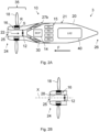
- the propulsion propeller 18 is mounted integrally with a drive shaft 19 whose longitudinal axis corresponds to the longitudinal axis X of the nacelle 20.
- the drive shaft 19 is mechanically coupled to the at least one electric motor 16, which is integrated into a motor system 31.
- the motor system 31 further comprises a gearbox not shown in the figures.
- the propulsion system 3 comprises several electric motors 16
- the drive shaft 19 is mechanically coupled to these electric motors via the gearbox.
- the engine system 31 is mounted at least partly inside the nacelle 20, at its first end 24, centered on the longitudinal axis X of the nacelle.
- the first end 25 of the air circulation channel 22 is such that the outer surface 28 of the air circulation channel 22, of cylindrical shape, surrounds the engine system 31.
- the engine system 31 comprises a fairing provided to facilitate the flow of air along said engine system.
- the mechanical connections between the engine system 31 and the nacelle are not shown.
- the rotation of the propulsion propeller 18 promotes the introduction of air into the first end 25 of the air circulation channel 22.
- the air circulates in the air circulation channel 22, between the cylindrical outer surface 28 and the engine system 31.
- the air then arrives in the part 35 of the air circulation channel 22 in which the air circulation channel 22 is unique, of circular section and comprises the fan 12.
- the fan 12 promotes the circulation of air in the air circulation channel.
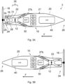
- a second end 27b of the air circulation channel 22 opens through a side wall 21 of the nacelle, between the first longitudinal end 24 of the nacelle and a second longitudinal end 26 of the nacelle, opposite the first longitudinal end of the nacelle.
- the second end 27b is for example scoop-shaped.
- the heat exchanger 30 is installed between the part 35 of the air circulation channel 22 and its second end 27b. According to a first alternative, the second end 27b of the air circulation channel 22 extends substantially over the entire perimeter of the side wall 21 of the nacelle.
- the heat exchanger 30 is then installed in a part of the air circulation channel 22 in which a section of the air circulation channel by a plane perpendicular to the longitudinal axis of the nacelle is crown-shaped.
- the air circulation channel 22 comprises several independent branches between its part 35 and its second end 27b.
- the second end 27b then comprises several independent parts distributed along the perimeter of the side wall 21 of the nacelle.
- the different independent parts correspond each to one of the branches of the air circulation channel 22 and they are preferably distributed symmetrically on the perimeter of the side wall 21 of the nacelle.
- the heat exchanger 30 then comprises several parts arranged in the different branches of the air circulation channel 22.
- the heat exchanger 30 is installed in a part of the air circulation channel in which the air circulation channel is of circular section, for example in the part 35.
- this hydrogen tank is for example housed in a part of the nacelle between the second end 27b of the air circulation channel 22 and the second longitudinal end 26 of the nacelle.
- the fuel cell assembly 15 as well as the assembly 14 of auxiliary equipment are also housed in the part of the nacelle between the second end 27b of the air circulation channel 22 and the second longitudinal end 26 of the nacelle.
- the propulsion system 3 comprises an air flow adjustment device, not shown in the figures, associated with the second end 27b of the air circulation channel 22.
- This air flow adjustment device corresponds for example to a set of flaps whose position can be adjusted to vary the air flow in the air circulation channel 22, in particular according to the cooling requirement of the electricity production system 10.
- the air circulation channel is of cylindrical shape and extends along the length of the nacelle, between the first end 25 of the air circulation channel 22 and a second end 27a of the air circulation channel opening near a second longitudinal end 26 of the nacelle, opposite the first longitudinal end 24 of the nacelle.
- this cylindrical shape is of circular section, the part 35 of the air circulation channel 22 then extends over almost the entire length of the nacelle 20.
- the heat exchanger 30 is then of circular section.
- the cylindrical shape of the air circulation channel 22 makes it possible to promote the flow of air in this air circulation channel and consequently to improve the cooling of the electricity production system 10.
- the propulsion system 3 comprises a device 33 for adjusting the air flow rate associated with the second end 27a of the air circulation channel 22.
- This device 33 for adjusting the air flow rate corresponds for example to a set of flaps whose position can be adjusted to vary the air flow rate in the air circulation channel 22, in particular according to the cooling requirement of the electricity production system 10.
- the fuel cells 15 and the set of auxiliary equipment 14 are housed in the nacelle around the air circulation channel 22, between the air circulation channel 22 and the side wall 21 of the nacelle.
- the air circulation channel 22 is similar to that of the third embodiment, except for the first end 25 already described.
- the first end 24 of the nacelle corresponds to the front of the nacelle and the second end 26 corresponds to the rear of the nacelle.
- the propulsion propeller 18 is therefore located close to the front of the nacelle.
- the air enters the air circulation channel 22 via the first end 25 and exits via the second end 27a or 27b.
- FIGS. 2B , 3B , 4B And 5B correspond to variants of the embodiments illustrated in the Figures 2A , 3A , 4A And 5A , in which the first end 24 of the nacelle corresponds to the rear of the nacelle and the second end 26 corresponds to the front of the nacelle.
- the propulsion propeller 18 is therefore located near the rear of the nacelle.
- air enters the air circulation channel 22 through the second end 27a or 27b and exits through the first end 25.
- the propulsion system 3 comprises two propulsion propellers mounted counter-rotatingly close to each other.
Landscapes
- Engineering & Computer Science (AREA)
- Aviation & Aerospace Engineering (AREA)
- Mechanical Engineering (AREA)
- Chemical & Material Sciences (AREA)
- Sustainable Energy (AREA)
- Life Sciences & Earth Sciences (AREA)
- Sustainable Development (AREA)
- Combustion & Propulsion (AREA)
- Power Engineering (AREA)
- Transportation (AREA)
- General Engineering & Computer Science (AREA)
- Manufacturing & Machinery (AREA)
- Chemical Kinetics & Catalysis (AREA)
- Electrochemistry (AREA)
- General Chemical & Material Sciences (AREA)
- Structures Of Non-Positive Displacement Pumps (AREA)
- Wind Motors (AREA)
Claims (15)
- Antriebssystem (3) für ein Luftfahrzeug (1), beinhaltend:- ein Stromerzeugungssystem (10), das eine Brennstoffzellenanordnung (15) beinhaltet;- mindestens einen Elektromotor (16), der von mindestens einem Teil der Brennstoffzellen mit Strom versorgt wird;- einen Antriebspropeller (18), der mit dem mindestens einen Elektromotor mechanisch gekoppelt ist; und- eine Gondel (20), die mindestens das Stromerzeugungssystem (10) und den mindestens einen Elektromotor (16) aufnimmt, wobei die Gondel einen Luftzirkulationskanal (22) beinhaltet, der dazu vorgesehen ist, die Kühlung des Stromerzeugungssystems (10) zu ermöglichen,wobei:- sich der Luftzirkulationskanal (22) im Inneren der Gondel von einem ersten Ende (25) des Luftzirkulationskanals, das sich an einem ersten Längsende (24) der Gondel (20) befindet, erstreckt;- der Luftzirkulationskanal einen Wärmetauscher (30) unterbringt, der dazu vorgesehen ist, die Kühlung des Stromerzeugungssystems (10) zu ermöglichen; und- sich der Antriebspropeller (18) in der Nähe des ersten Längsendes (24) der Gondel befindet,dadurch gekennzeichnet, dass mindestens ein Teil des Luftzirkulationskanals, der an das erste Ende des Luftzirkulationskanals angrenzt, von einer zylindrischen Außenfläche (28) begrenzt wird, die die Längsachse (X) der Gondel umgibt, wobei sich die Außenfläche (28) im Inneren der Gondel befindet.
- Antriebssystem nach Anspruch 1, dadurch gekennzeichnet, dass, gemäß der Länge der Gondel betrachtet, in mindestens einem Teil (35) der Gondel der Luftzirkulationskanal (22) einfach ausgeführt ist, einen kreisförmigen Querschnitt aufweist und einen Lüfter (12) aufnimmt, der dazu vorgesehen ist, die Luftzirkulation in diesem Luftzirkulationskanal zu unterstützen.
- Antriebssystem nach Anspruch 2, dadurch gekennzeichnet, dass der Lüfter (12) in dem Luftzirkulationskanal zwischen dem ersten Ende (25) des Luftzirkulationskanals und dem Wärmetauscher (30) aufgenommen ist.
- Antriebssystem nach einem der Ansprüche 1 bis 3, dadurch gekennzeichnet, dass der Antriebspropeller (18) drehbar um die Gondel (20) montiert ist.
- Antriebssystem nach dem vorhergehenden Anspruch, dadurch gekennzeichnet, dass es eine Vorrichtung zur Regelung des Luftdurchsatzes (32) beinhaltet, die mit dem ersten Ende (25) des Luftzirkulationskanals assoziiert ist.
- Antriebssystem nach einem der Ansprüche 1 bis 3, dadurch gekennzeichnet, dass der Antriebspropeller (18) fest an einer Antriebswelle (19) montiert ist, deren Längsachse der Längsachse der Gondel entspricht.
- Antriebssystem nach einem der vorhergehenden Ansprüche, dadurch gekennzeichnet, dass der Wärmetauscher (30) in einem Teil des Luftzirkulationskanals (22) installiert ist, in dem ein Querschnitt des Luftzirkulationskanals in einer zu der Längsachse der Gondel senkrechten Ebene kranzförmig ist.
- Antriebssystem nach einem der Ansprüche 1 bis 6, dadurch gekennzeichnet, dass der Wärmetauscher (30) in einem Teil des Luftzirkulationskanals installiert ist, in dem der Luftzirkulationskanal einen kreisförmigen Querschnitt aufweist.
- Antriebssystem nach dem vorhergehenden Anspruch, dadurch gekennzeichnet, dass der Luftzirkulationskanal zylindrisch ist und sich gemäß der Länge der Gondel zwischen dem ersten Ende (25) des Luftzirkulationskanals und einem zweiten Ende (27a) des Luftzirkulationskanals erstreckt und dabei in der Nähe eines zweiten Längsendes (26) der Gondel, das zu dem ersten Längsende (24) der Gondel entgegengesetzt ist, mündet.
- Antriebssystem nach einem der Ansprüche 1 bis 8, dadurch gekennzeichnet, dass ein zweites Ende (27b) des Luftzirkulationskanals (22) zwischen dem ersten Längsende (24) der Gondel und einem zweiten Längsende (26) der Gondel, das zu dem ersten Längsende der Gondel entgegengesetzt ist, durch eine Seitenwand (21) der Gondel mündet.
- Antriebssystem nach dem vorhergehenden Anspruch, dadurch gekennzeichnet, dass es einen Wasserstofftank (40) umfasst, der in der Gondel zwischen dem zweiten Ende (27b) des Luftzirkulationskanals und dem zweiten Längsende (26) der Gondel aufgenommen ist.
- Antriebssystem nach einem der vorhergehenden Ansprüche, dadurch gekennzeichnet, dass es eine Vorrichtung (33) zur Regelung des Luftdurchsatzes beinhaltet, die mit dem zweiten Ende (27a, 27b) des Luftzirkulationskanals (22) assoziiert ist.
- Antriebssystem nach einem der vorhergehenden Ansprüche, dadurch gekennzeichnet, dass das erste Längsende (24) der Gondel einem vorderen Längsende der Gondel entspricht.
- Antriebssystem nach einem der Ansprüche 1 bis 12, dadurch gekennzeichnet, dass das erste Längsende (24) der Gondel einem hinteren Längsende der Gondel entspricht.
- Luftfahrzeug, dadurch gekennzeichnet, dass es ein Antriebssystem (3) nach einem der vorhergehenden Ansprüche beinhaltet.
Applications Claiming Priority (1)
| Application Number | Priority Date | Filing Date | Title |
|---|---|---|---|
| FR2103181 | 2021-03-29 |
Publications (2)
| Publication Number | Publication Date |
|---|---|
| EP4067236A1 EP4067236A1 (de) | 2022-10-05 |
| EP4067236B1 true EP4067236B1 (de) | 2024-12-25 |
Family
ID=75690596
Family Applications (1)
| Application Number | Title | Priority Date | Filing Date |
|---|---|---|---|
| EP22162027.1A Active EP4067236B1 (de) | 2021-03-29 | 2022-03-15 | Elektrisches antriebssystem für ein luftfahrzeug |
Country Status (2)
| Country | Link |
|---|---|
| US (1) | US11866185B2 (de) |
| EP (1) | EP4067236B1 (de) |
Families Citing this family (11)
| Publication number | Priority date | Publication date | Assignee | Title |
|---|---|---|---|---|
| WO2022245427A2 (en) * | 2021-03-31 | 2022-11-24 | Zeroavia Ltd. | Refueling system for hydrogen fuel cell-powered aircraft |
| DE102021115226A1 (de) * | 2021-06-11 | 2022-12-15 | MTU Aero Engines AG | Luftfahrzeug mit einer Brennstoffzelle und Verfahren zum Betrieb einer Brennstoffzelle eines Luftfahrzeugs |
| GB2617596A (en) * | 2022-04-13 | 2023-10-18 | Greenjets Ltd | Electric propulsion systems |
| US12497188B2 (en) | 2023-08-14 | 2025-12-16 | The Boeing Company | Liquid hydrogen feed system for fuel cell powered aircraft |
| US20250058889A1 (en) * | 2023-08-14 | 2025-02-20 | The Boeing Company | Configuration for a LH2 Fuel Cell Aircraft with Distributed Systems |
| US20250059933A1 (en) * | 2023-08-14 | 2025-02-20 | The Boeing Company | Method of Nacelle Air Heat Exchanger Integration for a Hydrogen Fueled Fuel Cell Powered Aircraft |
| FR3158953A1 (fr) | 2024-02-05 | 2025-08-08 | Airbus Operations | Ensemble propulsif pour aéronef comportant un ventilateur d’extraction |
| DE102024103765A1 (de) * | 2024-02-09 | 2025-08-14 | MTU Aero Engines AG | Wärmetauscher-Tank-Anordnung für ein Flugzeug |
| FR3161419A1 (fr) * | 2024-04-17 | 2025-10-24 | Safran | Groupe propulsif d’aeronef comprenant une pile a combustible |
| US20250333185A1 (en) * | 2024-04-30 | 2025-10-30 | Airbus Operations Sas | Method for mounting a hydrogen box in a for a hydrogen-powered aircraft |
| CN119872899B (zh) * | 2025-03-27 | 2025-06-20 | 浙江银轮机械股份有限公司 | 尾段导流式旋翼模块及旋翼式飞行器 |
Family Cites Families (14)
| Publication number | Priority date | Publication date | Assignee | Title |
|---|---|---|---|---|
| US2214669A (en) * | 1937-10-27 | 1940-09-10 | Bristol Aeroplane Co Ltd | Air-cooled aircraft engine |
| US7550218B2 (en) * | 2001-10-11 | 2009-06-23 | Airbus Deutschland Gmbh | Apparatus for producing water onboard of a craft driven by a power plant |
| FR2873751B1 (fr) * | 2004-07-28 | 2006-09-29 | Snecma Moteurs Sa | Cone d'entree d'une turbomachine |
| US20140119903A1 (en) * | 2012-10-29 | 2014-05-01 | United Technologies Corporation | Gas Turbine Engine With Inlet Particle Separator and Thermal Management |
| FR3018503B1 (fr) * | 2014-03-13 | 2017-10-13 | Snecma | Nacelle comprenant un echangeur pour refroidir un flux d'air |
| US10221862B2 (en) * | 2015-04-24 | 2019-03-05 | United Technologies Corporation | Intercooled cooling air tapped from plural locations |
| US20170167438A1 (en) * | 2015-12-11 | 2017-06-15 | General Electric Company | Gas Turbine Engine |
| US10774741B2 (en) * | 2016-01-26 | 2020-09-15 | General Electric Company | Hybrid propulsion system for a gas turbine engine including a fuel cell |
| US10174665B2 (en) * | 2016-03-18 | 2019-01-08 | Pratt & Whitney Canada Corp. | Active control flow system and method of cooling and providing active flow control |
| GB201718141D0 (en) | 2017-11-02 | 2017-12-20 | Rolls Royce Plc | Thermal management system |
| US11414199B2 (en) | 2019-03-01 | 2022-08-16 | Textron Innovations Inc. | Fuel cell powered line-replaceable thrust module |
| US11427344B2 (en) * | 2019-03-01 | 2022-08-30 | Pratt & Whitney Canada Corp. | Cooling system configurations for an aircraft having hybrid-electric propulsion system |
| FR3104139B1 (fr) * | 2019-12-09 | 2021-12-17 | Airbus | Systeme de propulsion pour un aeronef, ledit systeme de propulsion comportant une pile a combustible |
| FR3106453B1 (fr) * | 2020-01-20 | 2021-12-10 | Safran Electrical & Power | Système de refroidissement d’un dispositif d’entrainement à plusieurs machines électriques. |
-
2022
- 2022-03-15 EP EP22162027.1A patent/EP4067236B1/de active Active
- 2022-03-23 US US17/701,818 patent/US11866185B2/en active Active
Also Published As
| Publication number | Publication date |
|---|---|
| US20220306306A1 (en) | 2022-09-29 |
| EP4067236A1 (de) | 2022-10-05 |
| US11866185B2 (en) | 2024-01-09 |
Similar Documents
| Publication | Publication Date | Title |
|---|---|---|
| EP4067236B1 (de) | Elektrisches antriebssystem für ein luftfahrzeug | |
| EP3007977B1 (de) | Elektrische antriebsanordnung für ein flugzeug | |
| EP4072943B1 (de) | Antriebssystem für ein flugzeug, wobei das antriebssystem eine brennstoffzelle umfasst | |
| EP2052967B1 (de) | Verbesserung an Drehflügelflugzeugen, die mit Turbotriebwerken ausgestattet sind | |
| CA2434492C (fr) | Assistance et secours a l'entrainement electrique d'accessoires | |
| EP3817978B1 (de) | Antriebsflugzeug und flugzeugsystem, angetrieben durch ein integriertes antriebssystem an der rückseite eines flugzeugrumpf | |
| EP1662095A2 (de) | Lagerschmierung für ein Gasturbinentriebwerk mit integriertem Generator | |
| FR2527266A1 (fr) | Propulseur a turbine a gaz pour missile | |
| EP2867498B1 (de) | Vorrichtung zur belüftung und stromversorgung eines flugzeugmotorcomputers | |
| WO2021148744A1 (fr) | Systeme de refroidissement d'un dispositif d'entrainement a plusieurs machines electriques | |
| CA2947249A1 (fr) | Assemblage pour turbomachine d'aeronef et son procede de montage | |
| FR3039134A1 (fr) | Aeronef avec un ensemble propulsif comprenant une soufflante a l'arriere du fuselage | |
| FR3073569A1 (fr) | Turbopropulseur comportant un mecanisme de reduction integrant un dispositif de generation de courant | |
| EP2839165B1 (de) | Kraftfahrzeuggebläse mit reduzierter achsengrösse | |
| FR3039206A1 (fr) | Turbomachine pour aeronef comportant une turbine libre dans le flux primaire | |
| WO2017118791A1 (fr) | Système de changement de pas pour turbopropulseur a doublet d'hélices contrarotatives amont | |
| EP3870812B1 (de) | Flugzeugturbomaschine ausgerüstet mit einer elektrischen maschine | |
| CA3163109C (fr) | Aeronef muni d'un systeme de refroidissement pour une pile a combustible embarquee | |
| FR3147915A1 (fr) | Arbre de rotor pour machine électrique tournante | |
| WO2024033585A1 (fr) | Turbomachine pour aeronef | |
| FR3132731A1 (fr) | Ensemble propulsif pour aéronef comprenant une turbomachine à gaz et une machine électrique avec un système de refroidissement monté en aval de la machine électrique et procédé d’utilisation associé | |
| FR3127532A1 (fr) | Module pour une turbomachine d’aeronef | |
| FR3131276A1 (fr) | Système de calage et dégivrage de pales d’une helice d’un aeronef | |
| FR2996590A1 (fr) | Helice comportant un pivot pourvu d'une cellule a effet peltier | |
| EP4010252B1 (de) | Luftfahrzeug |
Legal Events
| Date | Code | Title | Description |
|---|---|---|---|
| PUAI | Public reference made under article 153(3) epc to a published international application that has entered the european phase |
Free format text: ORIGINAL CODE: 0009012 |
|
| STAA | Information on the status of an ep patent application or granted ep patent |
Free format text: STATUS: EXAMINATION IS IN PROGRESS |
|
| 17P | Request for examination filed |
Effective date: 20220315 |
|
| AK | Designated contracting states |
Kind code of ref document: A1 Designated state(s): AL AT BE BG CH CY CZ DE DK EE ES FI FR GB GR HR HU IE IS IT LI LT LU LV MC MK MT NL NO PL PT RO RS SE SI SK SM TR |
|
| RBV | Designated contracting states (corrected) |
Designated state(s): AL AT BE BG CH CY CZ DE DK EE ES FI FR GB GR HR HU IE IS IT LI LT LU LV MC MK MT NL NO PL PT RO RS SE SI SK SM TR |
|
| GRAP | Despatch of communication of intention to grant a patent |
Free format text: ORIGINAL CODE: EPIDOSNIGR1 |
|
| STAA | Information on the status of an ep patent application or granted ep patent |
Free format text: STATUS: GRANT OF PATENT IS INTENDED |
|
| INTG | Intention to grant announced |
Effective date: 20241015 |
|
| GRAS | Grant fee paid |
Free format text: ORIGINAL CODE: EPIDOSNIGR3 |
|
| GRAA | (expected) grant |
Free format text: ORIGINAL CODE: 0009210 |
|
| STAA | Information on the status of an ep patent application or granted ep patent |
Free format text: STATUS: THE PATENT HAS BEEN GRANTED |
|
| AK | Designated contracting states |
Kind code of ref document: B1 Designated state(s): AL AT BE BG CH CY CZ DE DK EE ES FI FR GB GR HR HU IE IS IT LI LT LU LV MC MK MT NL NO PL PT RO RS SE SI SK SM TR |
|
| REG | Reference to a national code |
Ref country code: GB Ref legal event code: FG4D Free format text: NOT ENGLISH |
|
| REG | Reference to a national code |
Ref country code: CH Ref legal event code: EP |
|
| REG | Reference to a national code |
Ref country code: DE Ref legal event code: R096 Ref document number: 602022008970 Country of ref document: DE |
|
| REG | Reference to a national code |
Ref country code: IE Ref legal event code: FG4D Free format text: LANGUAGE OF EP DOCUMENT: FRENCH |
|
| REG | Reference to a national code |
Ref country code: LT Ref legal event code: MG9D |
|
| PG25 | Lapsed in a contracting state [announced via postgrant information from national office to epo] |
Ref country code: HR Free format text: LAPSE BECAUSE OF FAILURE TO SUBMIT A TRANSLATION OF THE DESCRIPTION OR TO PAY THE FEE WITHIN THE PRESCRIBED TIME-LIMIT Effective date: 20241225 |
|
| PG25 | Lapsed in a contracting state [announced via postgrant information from national office to epo] |
Ref country code: FI Free format text: LAPSE BECAUSE OF FAILURE TO SUBMIT A TRANSLATION OF THE DESCRIPTION OR TO PAY THE FEE WITHIN THE PRESCRIBED TIME-LIMIT Effective date: 20241225 |
|
| PG25 | Lapsed in a contracting state [announced via postgrant information from national office to epo] |
Ref country code: BG Free format text: LAPSE BECAUSE OF FAILURE TO SUBMIT A TRANSLATION OF THE DESCRIPTION OR TO PAY THE FEE WITHIN THE PRESCRIBED TIME-LIMIT Effective date: 20241225 |
|
| PG25 | Lapsed in a contracting state [announced via postgrant information from national office to epo] |
Ref country code: NO Free format text: LAPSE BECAUSE OF FAILURE TO SUBMIT A TRANSLATION OF THE DESCRIPTION OR TO PAY THE FEE WITHIN THE PRESCRIBED TIME-LIMIT Effective date: 20250325 |
|
| PG25 | Lapsed in a contracting state [announced via postgrant information from national office to epo] |
Ref country code: GR Free format text: LAPSE BECAUSE OF FAILURE TO SUBMIT A TRANSLATION OF THE DESCRIPTION OR TO PAY THE FEE WITHIN THE PRESCRIBED TIME-LIMIT Effective date: 20250326 Ref country code: LV Free format text: LAPSE BECAUSE OF FAILURE TO SUBMIT A TRANSLATION OF THE DESCRIPTION OR TO PAY THE FEE WITHIN THE PRESCRIBED TIME-LIMIT Effective date: 20241225 |
|
| PGFP | Annual fee paid to national office [announced via postgrant information from national office to epo] |
Ref country code: AT Payment date: 20250417 Year of fee payment: 4 |
|
| PG25 | Lapsed in a contracting state [announced via postgrant information from national office to epo] |
Ref country code: RS Free format text: LAPSE BECAUSE OF FAILURE TO SUBMIT A TRANSLATION OF THE DESCRIPTION OR TO PAY THE FEE WITHIN THE PRESCRIBED TIME-LIMIT Effective date: 20250325 |
|
| REG | Reference to a national code |
Ref country code: NL Ref legal event code: MP Effective date: 20241225 |
|
| PG25 | Lapsed in a contracting state [announced via postgrant information from national office to epo] |
Ref country code: NL Free format text: LAPSE BECAUSE OF FAILURE TO SUBMIT A TRANSLATION OF THE DESCRIPTION OR TO PAY THE FEE WITHIN THE PRESCRIBED TIME-LIMIT Effective date: 20241225 |
|
| REG | Reference to a national code |
Ref country code: AT Ref legal event code: MK05 Ref document number: 1753988 Country of ref document: AT Kind code of ref document: T Effective date: 20241225 |
|
| PG25 | Lapsed in a contracting state [announced via postgrant information from national office to epo] |
Ref country code: SM Free format text: LAPSE BECAUSE OF FAILURE TO SUBMIT A TRANSLATION OF THE DESCRIPTION OR TO PAY THE FEE WITHIN THE PRESCRIBED TIME-LIMIT Effective date: 20241225 |
|
| PG25 | Lapsed in a contracting state [announced via postgrant information from national office to epo] |
Ref country code: PL Free format text: LAPSE BECAUSE OF FAILURE TO SUBMIT A TRANSLATION OF THE DESCRIPTION OR TO PAY THE FEE WITHIN THE PRESCRIBED TIME-LIMIT Effective date: 20241225 |
|
| PG25 | Lapsed in a contracting state [announced via postgrant information from national office to epo] |
Ref country code: ES Free format text: LAPSE BECAUSE OF FAILURE TO SUBMIT A TRANSLATION OF THE DESCRIPTION OR TO PAY THE FEE WITHIN THE PRESCRIBED TIME-LIMIT Effective date: 20241225 |
|
| PG25 | Lapsed in a contracting state [announced via postgrant information from national office to epo] |
Ref country code: IS Free format text: LAPSE BECAUSE OF FAILURE TO SUBMIT A TRANSLATION OF THE DESCRIPTION OR TO PAY THE FEE WITHIN THE PRESCRIBED TIME-LIMIT Effective date: 20250425 |
|
| PG25 | Lapsed in a contracting state [announced via postgrant information from national office to epo] |
Ref country code: PT Free format text: LAPSE BECAUSE OF FAILURE TO SUBMIT A TRANSLATION OF THE DESCRIPTION OR TO PAY THE FEE WITHIN THE PRESCRIBED TIME-LIMIT Effective date: 20250428 |
|
| PG25 | Lapsed in a contracting state [announced via postgrant information from national office to epo] |
Ref country code: EE Free format text: LAPSE BECAUSE OF FAILURE TO SUBMIT A TRANSLATION OF THE DESCRIPTION OR TO PAY THE FEE WITHIN THE PRESCRIBED TIME-LIMIT Effective date: 20241225 |
|
| PG25 | Lapsed in a contracting state [announced via postgrant information from national office to epo] |
Ref country code: AT Free format text: LAPSE BECAUSE OF FAILURE TO SUBMIT A TRANSLATION OF THE DESCRIPTION OR TO PAY THE FEE WITHIN THE PRESCRIBED TIME-LIMIT Effective date: 20241225 Ref country code: RO Free format text: LAPSE BECAUSE OF FAILURE TO SUBMIT A TRANSLATION OF THE DESCRIPTION OR TO PAY THE FEE WITHIN THE PRESCRIBED TIME-LIMIT Effective date: 20241225 |
|
| PG25 | Lapsed in a contracting state [announced via postgrant information from national office to epo] |
Ref country code: SK Free format text: LAPSE BECAUSE OF FAILURE TO SUBMIT A TRANSLATION OF THE DESCRIPTION OR TO PAY THE FEE WITHIN THE PRESCRIBED TIME-LIMIT Effective date: 20241225 |
|
| PG25 | Lapsed in a contracting state [announced via postgrant information from national office to epo] |
Ref country code: CZ Free format text: LAPSE BECAUSE OF FAILURE TO SUBMIT A TRANSLATION OF THE DESCRIPTION OR TO PAY THE FEE WITHIN THE PRESCRIBED TIME-LIMIT Effective date: 20241225 |
|
| PG25 | Lapsed in a contracting state [announced via postgrant information from national office to epo] |
Ref country code: IT Free format text: LAPSE BECAUSE OF FAILURE TO SUBMIT A TRANSLATION OF THE DESCRIPTION OR TO PAY THE FEE WITHIN THE PRESCRIBED TIME-LIMIT Effective date: 20241225 |
|
| PG25 | Lapsed in a contracting state [announced via postgrant information from national office to epo] |
Ref country code: SE Free format text: LAPSE BECAUSE OF FAILURE TO SUBMIT A TRANSLATION OF THE DESCRIPTION OR TO PAY THE FEE WITHIN THE PRESCRIBED TIME-LIMIT Effective date: 20241225 |
|
| REG | Reference to a national code |
Ref country code: DE Ref legal event code: R097 Ref document number: 602022008970 Country of ref document: DE |
|
| PG25 | Lapsed in a contracting state [announced via postgrant information from national office to epo] |
Ref country code: DK Free format text: LAPSE BECAUSE OF FAILURE TO SUBMIT A TRANSLATION OF THE DESCRIPTION OR TO PAY THE FEE WITHIN THE PRESCRIBED TIME-LIMIT Effective date: 20241225 |
|
| PG25 | Lapsed in a contracting state [announced via postgrant information from national office to epo] |
Ref country code: MC Free format text: LAPSE BECAUSE OF FAILURE TO SUBMIT A TRANSLATION OF THE DESCRIPTION OR TO PAY THE FEE WITHIN THE PRESCRIBED TIME-LIMIT Effective date: 20241225 |
|
| REG | Reference to a national code |
Ref country code: CH Ref legal event code: H13 Free format text: ST27 STATUS EVENT CODE: U-0-0-H10-H13 (AS PROVIDED BY THE NATIONAL OFFICE) Effective date: 20251023 |
|
| PLBE | No opposition filed within time limit |
Free format text: ORIGINAL CODE: 0009261 |
|
| STAA | Information on the status of an ep patent application or granted ep patent |
Free format text: STATUS: NO OPPOSITION FILED WITHIN TIME LIMIT |
|
| PG25 | Lapsed in a contracting state [announced via postgrant information from national office to epo] |
Ref country code: LU Free format text: LAPSE BECAUSE OF NON-PAYMENT OF DUE FEES Effective date: 20250315 |
|
| 26N | No opposition filed |
Effective date: 20250926 |
|
| REG | Reference to a national code |
Ref country code: BE Ref legal event code: MM Effective date: 20250331 |
|
| PG25 | Lapsed in a contracting state [announced via postgrant information from national office to epo] |
Ref country code: BE Free format text: LAPSE BECAUSE OF NON-PAYMENT OF DUE FEES Effective date: 20250331 |
|
| PG25 | Lapsed in a contracting state [announced via postgrant information from national office to epo] |
Ref country code: CH Free format text: LAPSE BECAUSE OF NON-PAYMENT OF DUE FEES Effective date: 20250331 |
|
| PG25 | Lapsed in a contracting state [announced via postgrant information from national office to epo] |
Ref country code: IE Free format text: LAPSE BECAUSE OF NON-PAYMENT OF DUE FEES Effective date: 20250315 |
|
| PGFP | Annual fee paid to national office [announced via postgrant information from national office to epo] |
Ref country code: GB Payment date: 20260324 Year of fee payment: 5 |
|
| PGFP | Annual fee paid to national office [announced via postgrant information from national office to epo] |
Ref country code: DE Payment date: 20260319 Year of fee payment: 5 |
|
| PGFP | Annual fee paid to national office [announced via postgrant information from national office to epo] |
Ref country code: FR Payment date: 20260323 Year of fee payment: 5 |