EP4067214A1 - Running device - Google Patents
Running device Download PDFInfo
- Publication number
- EP4067214A1 EP4067214A1 EP20918056.1A EP20918056A EP4067214A1 EP 4067214 A1 EP4067214 A1 EP 4067214A1 EP 20918056 A EP20918056 A EP 20918056A EP 4067214 A1 EP4067214 A1 EP 4067214A1
- Authority
- EP
- European Patent Office
- Prior art keywords
- wheel
- support arm
- wheels
- running
- running direction
- Prior art date
- Legal status (The legal status is an assumption and is not a legal conclusion. Google has not performed a legal analysis and makes no representation as to the accuracy of the status listed.)
- Withdrawn
Links
Images




Classifications
-
- B—PERFORMING OPERATIONS; TRANSPORTING
- B62—LAND VEHICLES FOR TRAVELLING OTHERWISE THAN ON RAILS
- B62D—MOTOR VEHICLES; TRAILERS
- B62D61/00—Motor vehicles or trailers, characterised by the arrangement or number of wheels, not otherwise provided for, e.g. four wheels in diamond pattern
- B62D61/10—Motor vehicles or trailers, characterised by the arrangement or number of wheels, not otherwise provided for, e.g. four wheels in diamond pattern with more than four wheels
-
- B—PERFORMING OPERATIONS; TRANSPORTING
- B60—VEHICLES IN GENERAL
- B60G—VEHICLE SUSPENSION ARRANGEMENTS
- B60G5/00—Resilient suspensions for a set of tandem wheels or axles having interrelated movements
- B60G5/02—Resilient suspensions for a set of tandem wheels or axles having interrelated movements mounted on a single pivoted arm, e.g. the arm being rigid
-
- B—PERFORMING OPERATIONS; TRANSPORTING
- B60—VEHICLES IN GENERAL
- B60G—VEHICLE SUSPENSION ARRANGEMENTS
- B60G5/00—Resilient suspensions for a set of tandem wheels or axles having interrelated movements
- B60G5/02—Resilient suspensions for a set of tandem wheels or axles having interrelated movements mounted on a single pivoted arm, e.g. the arm being rigid
- B60G5/025—Resilient suspensions for a set of tandem wheels or axles having interrelated movements mounted on a single pivoted arm, e.g. the arm being rigid the arm being transverse to the longitudinal axis of the vehicle
-
- B—PERFORMING OPERATIONS; TRANSPORTING
- B60—VEHICLES IN GENERAL
- B60G—VEHICLE SUSPENSION ARRANGEMENTS
- B60G5/00—Resilient suspensions for a set of tandem wheels or axles having interrelated movements
- B60G5/04—Resilient suspensions for a set of tandem wheels or axles having interrelated movements with two or more pivoted arms, the movements of which are resiliently interrelated, e.g. the arms being rigid
- B60G5/043—Resilient suspensions for a set of tandem wheels or axles having interrelated movements with two or more pivoted arms, the movements of which are resiliently interrelated, e.g. the arms being rigid the arms being transverse to the longitudinal axis of the vehicle
-
- B—PERFORMING OPERATIONS; TRANSPORTING
- B62—LAND VEHICLES FOR TRAVELLING OTHERWISE THAN ON RAILS
- B62D—MOTOR VEHICLES; TRAILERS
- B62D63/00—Motor vehicles or trailers not otherwise provided for
- B62D63/02—Motor vehicles
-
- B—PERFORMING OPERATIONS; TRANSPORTING
- B62—LAND VEHICLES FOR TRAVELLING OTHERWISE THAN ON RAILS
- B62D—MOTOR VEHICLES; TRAILERS
- B62D65/00—Designing, manufacturing, e.g. assembling, facilitating disassembly, or structurally modifying motor vehicles or trailers, not otherwise provided for
- B62D65/02—Joining sub-units or components to, or positioning sub-units or components with respect to, body shell or other sub-units or components
- B62D65/18—Transportation, conveyor or haulage systems specially adapted for motor vehicle or trailer assembly lines
-
- B—PERFORMING OPERATIONS; TRANSPORTING
- B60—VEHICLES IN GENERAL
- B60G—VEHICLE SUSPENSION ARRANGEMENTS
- B60G2200/00—Indexing codes relating to suspension types
- B60G2200/30—Rigid axle suspensions
- B60G2200/318—Rigid axle suspensions two or more axles being mounted on a longitudinal rocking or walking beam
-
- B—PERFORMING OPERATIONS; TRANSPORTING
- B60—VEHICLES IN GENERAL
- B60G—VEHICLE SUSPENSION ARRANGEMENTS
- B60G2200/00—Indexing codes relating to suspension types
- B60G2200/30—Rigid axle suspensions
- B60G2200/32—Rigid axle suspensions pivoted
Definitions
- the present invention relates to a running device arranged on a running vehicle such as an automatic guided vehicle.
- FMS Flexible Manufacturing System
- machine tools are arranged appropriately in a plant and an automatic guided vehicle (running vehicle) is used to deliver a workpiece to be machined, a tool, etc. to each machine tool and also used to collect a machined workpiece, a used tool, etc. from each machine tool.
- This manufacturing system realizes an unmanned and automated production.
- Patent Literature 1 A known example of the automatic guided vehicle is disclosed in Patent Literature 1 listed below.
- This automatic guided vehicle has a distance measurement device that rotationally drives a light projector projecting a light and outputs distance measurement data based on receipt of a reflected light from an object to be measured, a map generator that generates map information based on the distance measurement data, and an obstacle sensor that senses an obstacle.
- a typical running device of an automatic guided vehicle has a frame, a first driven wheel part, a drive wheel part, and a second driven wheel part.
- the first driven wheel part, the drive wheel part, and the second driven wheel part are arranged at appropriate intervals along the running direction and connected to the frame.
- the first driven wheel part and the second driven wheel part each include left and right driven wheels, and the drive wheel part includes left and right drive wheels.
- the automatic guided vehicle runs by rotation of the left and right drive wheels, and the running direction of the automatic guided vehicle is controlled by controlling the numbers of rotations of the left and right drive wheels.
- the automatic guided vehicle is first operated, for example, by manual operation, to cause the automatic guided vehicle to run in a plant building, during which planar map information that defines an inner profile of the plant building and outer profiles of machine tools and other devices arranged in the plant building is generated by the map generator based on the distance measurement data measured by the distance measurement device.
- the automatic guided vehicle identifies the current position of itself (self position) in the plant building based on the distance measurement data measured by the distance measurement device and the map information previously generated by the map generator.
- the automatic guided vehicle autonomously runs tracklessly along a predetermined path based on the plant-building map information and the self position information to perform the delivery of workpieces and tools.
- An automatic guided vehicle does not always run in a plant building having only a flat area, but in some cases, runs in a plant building having not only a flat area but also an area with some bumps and dips. Further, in the case of using an autonomously running automatic guided vehicle, the running path for the automatic guided vehicle is sometimes set in an intentionally formed stepped area.
- This running device has a center frame and a pair of running parts (rocker-bogie mechanisms) symmetrically mounted to the center frame.
- Each running part includes a rocker frame pivotably supported by the center frame, a bogie frame pivotably supported on a first end of the rocker frame, and first, second, and third wheels respectively rotationally supported on a second end of the rocker frame and both ends of the bogie frame.
- the second wheels are drive wheels that are independent from each other, and the second wheels are each positioned between the associated first and third wheels that are driven wheels.
- the center frame has two pivot support members provided thereon that respectively support the bar members constituting the stabilizers such that the bar members are pivotable.
- the rocker frames each have support members respectively provided on the first and second ends thereof that each support the corresponding bar member such that the bar member is slidable.
- the configuration in which the pair of rocker-bogie mechanisms are respectively pivotably supported on both sides of the center frame enables the running device to run while maintaining a stable posture even when one of the rocker-bogie mechanisms climbs over a step or climbs on or down a step, and also enables the center frame to maintain its own horizontality even when the rocker-bogie mechanisms climb over a step or climb on or down a step. Further, increase of the overall height of this running device is suppressed because the rocker frames constituting the rocker-bogie mechanisms extend horizontally, so that stable running of the running device is ensured.
- the present invention has been achieved in view of the above-described circumstances, and an object of the invention is to provide a running device which has a simple structure and therefore can be manufactured at a low cost.
- the present invention provides a running device arranged on a running vehicle, including:
- the first left support arm and first right support arm constituting the first wheel part are each swingable within a vertical plane extending along the running direction, and the second support arm constituting the second wheel part is swingable within a vertical plane perpendicular to the running direction.
- the frame is supported by six wheels, namely, the two first left wheels arranged on both sides of the first left support arm, the two first right wheels arranged on both sides of the first right support arm, and the second left wheel and second right wheel arranged on both sides of the second support arm.
- the first left support arm swings so that the difference in level of the step is absorbed and all the wheels of the running device are thereby kept in contact with the floor surface.
- the first right support arm swings so that the difference in level of the step is absorbed and all the wheels of the running device are thereby kept in contact with the ground surface.
- the second support arm swings so that the difference in level of the step is absorbed and all the wheels of the running device are thereby kept in contact with the ground surface.
- the running device when a wheel of the running device runs onto a step on the ground, the corresponding one of the first left support arm, first right support arm, and second support arm swings so that the difference in level of the step is absorbed and all the wheels of the running device are thereby kept in contact with the ground surface, which enables the running device to run stably.
- this running device is configured such that the wheels are supported by three swingably-supported support arms, namely, the first left support arm, the first right support arm, and the second support arm. Therefore, this running device has a simple structure as compared with the conventional running device and therefore can be manufactured at a low cost.
- the running device according to the present invention may have a configuration in which:
- the frame is supported by eight wheels in total, namely, the two first left wheels arranged on the first left support arm, the two first right wheels arranged on the first right support arm, the two second left wheels arranged on the third left support arm, and the two second right wheels arranged on the third right support arm.
- the swinging motions of the first left support arm, first right support arm, and second support arm are also capable of absorbing a difference in level on the ground. Therefore, the running device is capable of absorbing more various types of unevenness formed on the ground.
- the running device according to the present invention may have a configuration in which at least one of the first left wheels and second left wheel or wheels and at least one of the first right wheels and second right wheel or wheels are drive wheels.
- each of the wheels other than the drive wheels may be composed of a universal wheel.
- each of the wheels other than the drive wheels may be composed of an omni wheel.
- the running device when a wheel of the running device runs onto a step on the ground, the corresponding one of the first left support arm, first right support arm, and second support arm swings so that the difference in level of the step is absorbed and all the wheels of the running device are thereby kept in contact with the ground surface, which enables the running device to run stably.
- the running device is configured such that the wheels are supported by three swingably-supported support arms, namely, the first left support arm, the first right support arm, and the second support arm. Therefore, the running device has a simple structure as compared with the conventional running device and therefore can be manufactured at a low cost.
- an automatic guided vehicle 1 has a running device 10, a support base 2 having a rectangular shape in plan view and arranged on the running device 10, sensors 5 respectively arranged on three corners of an upper surface of the support base 2, a cover 3 surrounding the support base 2, and a liftable table 4 having a rectangular shape in plan view and arranged on the support base 2 in a manner to be liftable up/down.
- the liftable table 4 lifts up/down by being driven by a lifting mechanism that is not illustrated in the drawings.
- the running device 10 and the lifting mechanism are controlled by a controller that is not illustrated in the drawings.
- the running device 10 has a frame 11 and a first wheel part 15 and a second wheel part 35 respectively arranged on the front side and the rear side with an appropriate distance therebetween along the running direction (the direction indicated by arrow R) and connected to the frame 11.
- the frame 11 is formed to have, in plan view, spaces cut out appropriately for arranging necessary structural objects therein and have a hollow interior for the sake of weight reduction.
- the first wheel part 15 consists of a first left wheel unit 16 and a first right wheel unit 25 respectively disposed on the left side and the right side with respect to the running direction.
- the first left wheel unit 16 includes a first left support arm 17 arranged on a left side surface of the frame 11 and first left wheels 19, 21 respectively supported on both ends of the first left support arm 17 in a manner to be rotatable about horizontal axles 20, 22 perpendicular to the running direction.
- the first right wheel unit 25 includes a first right support arm 26 arranged on a right side surface of the frame 11 and first right wheels 28, 30 respectively supported on both ends of the first right support arm 26 in a manner to be rotatable about horizontal axles 29, 31 perpendicular to the running direction.
- the first right support arm 26 is supported by a support shaft 27 arranged on the right side surface of the frame 11 so as to be swingable in the directions indicated by arrow D-E in FIG. 3 within a vertical plane extending along the running direction.
- the first left support arm 17 is supported by a support shaft 18 arranged on the left side surface of the frame 11 so as to be swingable in directions identical to the arrow D-E directions within a vertical plane extending along the running direction.
- the first left wheel 19 and the first right wheel 28, which are disposed on the front side in the running direction, are driven wheels and the first left wheel 21 and the first right wheel 30, which are disposed on the rear side in the running direction, are drive wheels.
- the first left wheel 21 is connected to a motor 23 via a decelerator 24 arranged on the first left support arm 17 so that the first left wheel 21 rotates by being driven by the motor 23.
- the first right wheel 30 is connected to a motor 32 via a decelerator 33 arranged on the first right support arm 26 so that the first right wheel 30 rotates by being driven by the motor 32.
- the second wheel part 35 includes a second support arm 36 arranged on the rear side of the frame 11 in the running direction.
- the second support arm 36 is supported by a support shaft 37 arranged on a rear side surface of the frame 11 so as to be swingable in the directions indicated by arrow F-G in FIG. 4 within a vertical plane perpendicular to the running direction.
- the second support arm 36 has a second left wheel 38 and a second right wheel 40 respectively on both ends thereof that are respectively supported in a manner to be rotatable about horizontal axles 39, 41 perpendicular to the running direction. Note that the second left wheel 38 and the second right wheel 40 are driven wheels.
- the first left wheel 19, the first right wheel 28, the second left wheel, 38, and the second right wheel 40 have the same configuration and they are each composed of an omni wheel. Although the following description is directed to the first left wheel 19 as a representative one that is illustrated in FIGS. 5 and 6 , the first right wheel 28, the second left wheel 38, and the second right wheel 40 are also configured in the same manner. Note that the first left wheel 21 and the first right wheel 30 are each composed of an ordinary wheel; therefore, detailed description of them is omitted.
- the first left wheel 19 consists of a body 19a having a center hole 19b formed in the center thereof for inserting the axle 20 therein, rollers 19c, 19d, 19e arranged on the right side of the body 19a in FIG. 6 , and rollers 19f, 19g, 19h arranged on the left side of the body 19a in FIG. 6 .
- the body 19a has a disk-shaped base, and the base has ribs formed on the left and right sides thereof for supporting the rollers 19c, 19d, 19e, 19f, 19g, 19h in vertical planes such that the rollers 19c, 19d, 19e, 19f, 19g, 19h are each rotatable.
- the rollers 19c, 19d, 19e, 19f, 19g, 19h have a drum-like shape with the same curvature and are respectively rotatably supported by support shafts that are supported by the ribs so as to be positioned in vertical planes.
- the rollers 19c, 19d, 19e are arranged at equal intervals in the circumferential direction of the body 19a, and the rollers 19f, 19g, 19h are also arranged at equal intervals in the circumferential direction of the body 19a.
- the rollers 19c, 19d, 19e and the rollers 19f, 19g, 19h are arranged such that they are phase-shifted 60° relative to each other in the circumferential direction.
- rollers 19c, 19d, 19e are arranged such that outer surfaces thereof are located on the same arc in a vertical plane including their support shafts.
- rollers 19f, 19g, 19h are arranged such that outer surfaces thereof are located on the same arc in a vertical plane including their support shafts.
- the first left wheel 19 is configured such that rotation of the first left wheel 19 about the axle 20 advances the first left wheel 19 in the rotating direction and rotation of each roller 19c, 19d, 19e, 19f, 19g, 19h slides the first left wheel 19 in a horizontal direction intersecting with the rotating direction and the axle 20.
- the automatic guided vehicle 1 Under control by the controller (not illustrated), the automatic guided vehicle 1 runs in accordance with driving of the motors 23, 32 and the liftable table 4 lifts up/down in accordance with driving of the lifting mechanism.
- the automatic guided vehicle 1 runs in a plant
- the first right wheel 28 runs onto a step S provided in the plant as shown in FIG. 7
- the first right support arm 26 swings in the arrow D direction, whereby the first right wheel 30 as a drive wheel as well as the first left wheels 19, 21, the first right wheel 28, the second left wheel 38, and the second right wheel 40 are all kept in contact with the ground surface.
- the first right support arm 26 swings in the arrow E direction, whereby the first left wheels 19, 21, the first right wheels 28, 30, the second left wheel 38, and the second right wheel 40 are all kept in contact with the ground surface.
- the first left support arm 17 swings in the arrow D direction, whereby the first left wheel 21 as a drive wheel as well as the first left wheel 19, the first right wheels 28, 30, the second left wheel 38, and the second right wheel 40 are all kept in contact with the ground surface.
- the first left support arm 17 swings in the arrow E direction, whereby the first left wheels 19, 21, the first right wheels 28, 30, the second left wheel 38, and the second right wheel 40 are all kept in contact with the ground surface.
- the second support arm 36 swings in the arrow F direction, whereby the first left wheels 19, 21, the first right wheels 28, 30, the second left wheel 38, and the second right wheel 40 are all kept in contact with the ground surface.
- the second support arm 36 swings in the arrow G direction, whereby the first left wheels 19, 21, the first right wheels 28, 30, the second left wheel 38, and the second right wheel 40 are all kept in contact with the ground surface.
- the running device 10 of the automatic guided vehicle 1 is configured such that the first left wheels 19, 21, the first right wheels 28, 30, and the second left and right wheels 38, 40 are respectively supported by the first left support arm 17, the first right support arm 26, and the second support arm 36 that are swingably supported. Therefore, the running device 10 has a simple structure as compared with the conventional running device and therefore can be manufactured at a low cost.
- the swinging motions of the first left support arm 17, first right support arm 26, and second support arm 36 also provide a shock-absorbing effect; therefore, it is not necessary to provide a suspension that is conventionally required.
- the running device 10 has a simple structure as compared with the conventional running device and therefore can be manufactured at a low cost.
- the first left wheel 19, the first right wheel 28, the second left wheel 38, and the second right wheel 40, which are driven wheels, are each composed of an omni wheel; therefore, when the running direction of the automatic guided vehicle 1 that is running in a predetermined direction needs to be changed to another direction with any of these wheels in contact with a step, the running direction can be changed smoothly.
- the running direction of the automatic guided vehicle 1 is changed with the second right wheel 40 in contact with a step S' as shown in FIG. 9 , the running direction can be changed without any special preliminary operation.
- a universal wheel 60 as illustrated in FIGS. 10 and 11 is conventionally known as a driven wheel.
- This universal wheel 60 consists of, for example, a base plate 61 to be attached to a lower surface of the first left support arm 17, first right support arm 26, or second support arm 36, a rotating plate 62 mounted to a lower surface of the base plate 61, support plates 63, 63 arranged with a predetermined distance therebetween on a lower surface of the rotating plate 62 to extend down from the lower surface of the rotating plate 62, a support shaft 65 supported by the support plates 63, 63, and a wheel 64 rotatably supported by the support shaft 65 between the support plates 63, 63.
- This universal wheel 60 is configured such that the wheel 64 is turned in a horizontal plane by horizontal rotation of the rotating plate 62 and the running direction of the wheel 64 is changed by this turning of the wheel 64.
- the changing of the running direction of the universal wheel 60 requires turning of the wheel 64 to a desired direction and also requires a distance for movement for performing the turning. Therefore, for example, in the case where the running direction of the automatic guided wheel 1 is changed by 90° either to the left or to the right with the wheel 64 of the universal wheel 60 in contact with the step S' similarly to in FIG. 9 , the step S' obstructs the turning of the wheel 64; consequently, the running direction of the automatic guided vehicle 1 cannot be changed.
- the running device according to the present invention may be configured as illustrated in FIG. 12 .
- the thus-configured running device 10' has a second wheel part 35' instead of the second wheel part 35 in the above-described embodiment.
- the running device 10' differs in configuration from the above-described running device 10.
- the other components of the running device 10' are the same as those of the running device 10. Therefore, in FIG. 12 , the same components are denoted by the same reference numerals as used for the running device 10.
- the second wheel part 35' includes a third left support arm 45 and a third right support arm 49 respectively arranged on both ends of the second support arm 36.
- the third left support arm 45 has second left wheels 38, 47 respectively supported on both ends thereof in a manner to be rotatable about horizontal axles 39, 48 perpendicular to the running direction.
- the third right support arm 49 has second right wheels 40, 51 respectively supported on both ends thereof in a manner to be rotatable about horizontal axles 41, 52 perpendicular to the running direction.
- the frame 11 is supported by eight wheels in total, namely, the two first left wheels 19, 21 arranged on the first left support arm 17, the two first right wheels 28, 30 arranged on the first right support arm 26, the two second left wheels 38, 47 arranged on the third left support arm 45, and the two second right wheels 40, 51 arranged on the third right support arm 49. Further, besides the swinging motions of the first left support arm 17, first right support arm 26, and second support arm 36, the swinging motions of the third left support arm 45 and third right support arm 49 are also capable of absorbing a difference in level on the ground. Therefore, the running device 10' is capable of absorbing more various types of unevenness formed on the ground.
- the first left wheel 21 and the first right wheel 30 are drive wheels.
- the present invention is not limited to this configuration, and a configuration is possible in which wheels other than the first left wheel 21 and the first right wheel 30 are drive wheels.
- the running device 10 may have a configuration in which either of the first left wheel 19 and second left wheel 38 and either of the first right wheel 28 and second right wheel 40 are drive wheels.
- the running device 10' may have a configuration in which the first left wheel 19 and either of the second left wheels 38, 47 are drive wheels and the first right wheel 28 and either of the second right wheels 40, 51 are drive wheels.
- each of the wheels as a driven wheel is composed of an omni wheel.
- the present invention is not limited to this configuration.
- the disadvantage as described above is supposed to occur in changing the running direction, the universal wheel 60 as illustrated in FIGS. 10 and 11 may be used for the wheels as driven wheels because it also has advantages, such as that it is relatively inexpensive.
Landscapes
- Engineering & Computer Science (AREA)
- Mechanical Engineering (AREA)
- Chemical & Material Sciences (AREA)
- Combustion & Propulsion (AREA)
- Transportation (AREA)
- Manufacturing & Machinery (AREA)
- Handcart (AREA)
- Automobile Manufacture Line, Endless Track Vehicle, Trailer (AREA)
- Platform Screen Doors And Railroad Systems (AREA)
Abstract
Description
- 0001 The present invention relates to a running device arranged on a running vehicle such as an automatic guided vehicle.
- 0002 For example, in a manufacturing system called FMS (Flexible Manufacturing System), machine tools are arranged appropriately in a plant and an automatic guided vehicle (running vehicle) is used to deliver a workpiece to be machined, a tool, etc. to each machine tool and also used to collect a machined workpiece, a used tool, etc. from each machine tool. This manufacturing system realizes an unmanned and automated production.
- 0003 A known example of the automatic guided vehicle is disclosed in
Patent Literature 1 listed below. This automatic guided vehicle has a distance measurement device that rotationally drives a light projector projecting a light and outputs distance measurement data based on receipt of a reflected light from an object to be measured, a map generator that generates map information based on the distance measurement data, and an obstacle sensor that senses an obstacle. - 0004 A typical running device of an automatic guided vehicle has a frame, a first driven wheel part, a drive wheel part, and a second driven wheel part. The first driven wheel part, the drive wheel part, and the second driven wheel part are arranged at appropriate intervals along the running direction and connected to the frame. The first driven wheel part and the second driven wheel part each include left and right driven wheels, and the drive wheel part includes left and right drive wheels. The automatic guided vehicle runs by rotation of the left and right drive wheels, and the running direction of the automatic guided vehicle is controlled by controlling the numbers of rotations of the left and right drive wheels.
- 0005 In using this automatic guided vehicle, the automatic guided vehicle is first operated, for example, by manual operation, to cause the automatic guided vehicle to run in a plant building, during which planar map information that defines an inner profile of the plant building and outer profiles of machine tools and other devices arranged in the plant building is generated by the map generator based on the distance measurement data measured by the distance measurement device.
- 0006 Further, the automatic guided vehicle identifies the current position of itself (self position) in the plant building based on the distance measurement data measured by the distance measurement device and the map information previously generated by the map generator. Thus, the automatic guided vehicle autonomously runs tracklessly along a predetermined path based on the plant-building map information and the self position information to perform the delivery of workpieces and tools.
- 0007 An automatic guided vehicle does not always run in a plant building having only a flat area, but in some cases, runs in a plant building having not only a flat area but also an area with some bumps and dips. Further, in the case of using an autonomously running automatic guided vehicle, the running path for the automatic guided vehicle is sometimes set in an intentionally formed stepped area.
- 0008 In the case where the above-described automatic guided vehicle runs in an area with bumps and dips or in an intentionally formed stepped area, it is possible that the drive wheels leave the ground and cannot come into contact with the ground surface when the first driven wheel part or the second driven wheel part runs onto a bump or a step. In such a case, the automatic guided vehicle loses its thrust force and goes out of control, so that the automatic guided vehicle cannot continue running.
- 0009 In view of these circumstances, a running device as disclosed in
Patent Literature 2 listed below has been proposed. This running device has a center frame and a pair of running parts (rocker-bogie mechanisms) symmetrically mounted to the center frame. Each running part includes a rocker frame pivotably supported by the center frame, a bogie frame pivotably supported on a first end of the rocker frame, and first, second, and third wheels respectively rotationally supported on a second end of the rocker frame and both ends of the bogie frame. The second wheels are drive wheels that are independent from each other, and the second wheels are each positioned between the associated first and third wheels that are driven wheels. - 0010 Between the rocker frames, two stabilizers, which are each constituted by a bar member, are respectively provided between the first ends and between the second ends. The center frame has two pivot support members provided thereon that respectively support the bar members constituting the stabilizers such that the bar members are pivotable. The rocker frames each have support members respectively provided on the first and second ends thereof that each support the corresponding bar member such that the bar member is slidable.
- 0011 The configuration in which the pair of rocker-bogie mechanisms are respectively pivotably supported on both sides of the center frame enables the running device to run while maintaining a stable posture even when one of the rocker-bogie mechanisms climbs over a step or climbs on or down a step, and also enables the center frame to maintain its own horizontality even when the rocker-bogie mechanisms climb over a step or climb on or down a step. Further, increase of the overall height of this running device is suppressed because the rocker frames constituting the rocker-bogie mechanisms extend horizontally, so that stable running of the running device is ensured.
- 0012
- Patent Literature 1:
Japanese Unexamined Patent Application Publication No. 2019-8359 - Patent Literature 2:
Japanese Unexamined Patent Application Publication No. 2017-222297 - 0013 Although the above-described running device disclosed in
Patent Literature 2 provides the above-described advantages, it has a complicated structure since the bogie frames are pivotably supported on the first ends of the rocker frames that are also pivotably supported by the center frame, and besides, between the rocker frames, the two stabilizers each constituted by a bar member are respectively provided between the first ends and between the second ends, which causes an increase in equipment cost. - 0014 In the field of equipment such as plant equipment, cost reduction is always desired. The above-described running device is no exception, that is to say, cost reduction is desired for the above-described running device.
- 0015 The present invention has been achieved in view of the above-described circumstances, and an object of the invention is to provide a running device which has a simple structure and therefore can be manufactured at a low cost.
- 0016 To solve the above-described problem, the present invention provides a running device arranged on a running vehicle, including:
- a frame; and
- a first wheel part and a second wheel part arranged with an appropriate distance therebetween along a running direction and connected to the frame,
- the first wheel part including a first left support arm and a first right support arm respectively disposed on a left side and a right side with respect to the running direction and each connected to the frame in a manner to be swingable within a vertical plane extending along the running direction,
- the second wheel part including a second support arm connected to the frame in a manner to be swingable within a vertical plane perpendicular to the running direction,
- the first left support arm having a first left wheel on each of both sides of a center of swinging thereof, the first left wheels being each supported in a manner to be rotatable about a horizontal axle perpendicular to the running direction,
- the first right support arm having a first right wheel on each of both sides of a center of swinging thereof, the first right wheels being each supported in a manner to be rotatable about a horizontal axle perpendicular to the running direction,
- the second support arm having a second left wheel and a second right wheel respectively on both sides of a center of swinging thereof, the second left wheel and the second right wheel being each supported in a manner to be rotatable about an axle perpendicular to the running direction,
- the center of swinging of the first left support arm being positioned on a line connecting centers of the two first left wheels,
- the center of swinging of the first right support arm being positioned on a line connecting centers of the two first right wheels.
- 0017 In the thus-configured running device, the first left support arm and first right support arm constituting the first wheel part are each swingable within a vertical plane extending along the running direction, and the second support arm constituting the second wheel part is swingable within a vertical plane perpendicular to the running direction. Further, the frame is supported by six wheels, namely, the two first left wheels arranged on both sides of the first left support arm, the two first right wheels arranged on both sides of the first right support arm, and the second left wheel and second right wheel arranged on both sides of the second support arm.
- 0018 Therefore, when one of the first left wheels arranged on both sides of the first left support arm runs onto a step on the ground, the first left support arm swings so that the difference in level of the step is absorbed and all the wheels of the running device are thereby kept in contact with the floor surface. Further, also when one of the first right wheels arranged on both sides of the first right support arm runs onto a step on the ground, the first right support arm swings so that the difference in level of the step is absorbed and all the wheels of the running device are thereby kept in contact with the ground surface. Furthermore, also when one of the second left wheel and second right wheel arranged on both sides of the second support arm runs onto a step on the ground, the second support arm swings so that the difference in level of the step is absorbed and all the wheels of the running device are thereby kept in contact with the ground surface.
- 0019 Thus, with the running device according to the present invention, when a wheel of the running device runs onto a step on the ground, the corresponding one of the first left support arm, first right support arm, and second support arm swings so that the difference in level of the step is absorbed and all the wheels of the running device are thereby kept in contact with the ground surface, which enables the running device to run stably.
- 0020 Further, this running device is configured such that the wheels are supported by three swingably-supported support arms, namely, the first left support arm, the first right support arm, and the second support arm. Therefore, this running device has a simple structure as compared with the conventional running device and therefore can be manufactured at a low cost.
- 0021 The running device according to the present invention may have a configuration in which:
- the second support arm of the second wheel part has a third left support arm and a third right support arm respectively on both sides of the center of swinging thereof, the third left support arm and the third right support arm being each swingable within a plane extending along the running direction;
- the third left support arm has the second left wheel on each of both sides of a center of swinging thereof, the second left wheels being each supported in a manner to be rotatable about an axle perpendicular to the running direction; and
- the third right support arm has the second right wheel on each of both sides of a center of swinging thereof, the second right wheels being each supported in a manner to be rotatable about an axle perpendicular to the running direction.
- 0022 In the thus-configured running device, the frame is supported by eight wheels in total, namely, the two first left wheels arranged on the first left support arm, the two first right wheels arranged on the first right support arm, the two second left wheels arranged on the third left support arm, and the two second right wheels arranged on the third right support arm. Further, besides the swinging motions of the first left support arm, first right support arm, and second support arm, the swinging motions of the third left support arm and third right support arm are also capable of absorbing a difference in level on the ground. Therefore, the running device is capable of absorbing more various types of unevenness formed on the ground.
- 0023 Further, the running device according to the present invention may have a configuration in which at least one of the first left wheels and second left wheel or wheels and at least one of the first right wheels and second right wheel or wheels are drive wheels.
- 0024 Furthermore, each of the wheels other than the drive wheels may be composed of a universal wheel. Alternatively, each of the wheels other than the drive wheels may be composed of an omni wheel.
- 0025 As described above, with the running device according to the present invention, when a wheel of the running device runs onto a step on the ground, the corresponding one of the first left support arm, first right support arm, and second support arm swings so that the difference in level of the step is absorbed and all the wheels of the running device are thereby kept in contact with the ground surface, which enables the running device to run stably.
- 0026 Further, the running device according to the present invention is configured such that the wheels are supported by three swingably-supported support arms, namely, the first left support arm, the first right support arm, and the second support arm. Therefore, the running device has a simple structure as compared with the conventional running device and therefore can be manufactured at a low cost. Brief Description of Drawings
- 0027
-
FIG. 1 is a perspective view illustrating an automatic guided vehicle according to a specific embodiment of the present invention; -
FIG. 2 is a plan view illustrating a running device according to the embodiment; -
FIG. 3 is a front view of the running device as viewed in the direction of arrow A inFIG. 2 ; -
FIG. 4 is a side view of the running device as viewed in the direction of arrow B inFIG. 2 ; -
FIG. 5 is a front view illustrating an omni wheel in the embodiment; -
FIG. 6 is a side view of the omni wheel as viewed in the direction of arrow C inFIG. 5 ; -
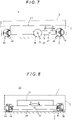
FIG. 7 is an illustrative diagram illustrating an action of the running device according to the embodiment; -
FIG. 8 is an illustrative diagram illustrating an action of the running device according to the embodiment; -
FIG. 9 is an illustrative diagram illustrating an action of the running device according to the embodiment; -
FIG. 10 is a front view illustrating a driven wheel in another embodiment of the present invention; -
FIG. 11 is a side view of the driven wheel as viewed in the direction of arrow D inFIG. 10 ; and -
FIG. 12 is a plan view illustrating a running device according to a further embodiment of the present invention. - 0028 Hereinafter, a specific embodiment of the present invention will be described with reference to the drawings.
- 0029 As illustrated in
FIGS. 1 and2 , an automatic guidedvehicle 1 according to this embodiment has a runningdevice 10, asupport base 2 having a rectangular shape in plan view and arranged on the runningdevice 10,sensors 5 respectively arranged on three corners of an upper surface of thesupport base 2, acover 3 surrounding thesupport base 2, and a liftable table 4 having a rectangular shape in plan view and arranged on thesupport base 2 in a manner to be liftable up/down. Note that the liftable table 4 lifts up/down by being driven by a lifting mechanism that is not illustrated in the drawings. The runningdevice 10 and the lifting mechanism (not illustrated) are controlled by a controller that is not illustrated in the drawings. - 0030 As illustrated in
FIGS.2 to 4 , the runningdevice 10 has aframe 11 and afirst wheel part 15 and asecond wheel part 35 respectively arranged on the front side and the rear side with an appropriate distance therebetween along the running direction (the direction indicated by arrow R) and connected to theframe 11. Note that theframe 11 is formed to have, in plan view, spaces cut out appropriately for arranging necessary structural objects therein and have a hollow interior for the sake of weight reduction. - 0031 The
first wheel part 15 consists of a firstleft wheel unit 16 and a firstright wheel unit 25 respectively disposed on the left side and the right side with respect to the running direction. The firstleft wheel unit 16 includes a firstleft support arm 17 arranged on a left side surface of theframe 11 and firstleft wheels left support arm 17 in a manner to be rotatable abouthorizontal axles - 0032 The first
right wheel unit 25 includes a firstright support arm 26 arranged on a right side surface of theframe 11 and firstright wheels right support arm 26 in a manner to be rotatable abouthorizontal axles - 0033 The first
right support arm 26 is supported by asupport shaft 27 arranged on the right side surface of theframe 11 so as to be swingable in the directions indicated by arrow D-E inFIG. 3 within a vertical plane extending along the running direction. Similarly, the firstleft support arm 17 is supported by asupport shaft 18 arranged on the left side surface of theframe 11 so as to be swingable in directions identical to the arrow D-E directions within a vertical plane extending along the running direction. - 0034 Note that, in this embodiment, the first
left wheel 19 and the firstright wheel 28, which are disposed on the front side in the running direction, are driven wheels and the firstleft wheel 21 and the firstright wheel 30, which are disposed on the rear side in the running direction, are drive wheels. The firstleft wheel 21 is connected to amotor 23 via adecelerator 24 arranged on the firstleft support arm 17 so that the firstleft wheel 21 rotates by being driven by themotor 23. Similarly, the firstright wheel 30 is connected to amotor 32 via adecelerator 33 arranged on the firstright support arm 26 so that the firstright wheel 30 rotates by being driven by themotor 32. - 0035 The
second wheel part 35 includes asecond support arm 36 arranged on the rear side of theframe 11 in the running direction. Thesecond support arm 36 is supported by asupport shaft 37 arranged on a rear side surface of theframe 11 so as to be swingable in the directions indicated by arrow F-G inFIG. 4 within a vertical plane perpendicular to the running direction. Further, thesecond support arm 36 has a secondleft wheel 38 and a secondright wheel 40 respectively on both ends thereof that are respectively supported in a manner to be rotatable abouthorizontal axles left wheel 38 and the secondright wheel 40 are driven wheels. - 0036 The first
left wheel 19, the firstright wheel 28, the second left wheel, 38, and the secondright wheel 40 have the same configuration and they are each composed of an omni wheel. Although the following description is directed to the firstleft wheel 19 as a representative one that is illustrated inFIGS. 5 and 6 , the firstright wheel 28, the secondleft wheel 38, and the secondright wheel 40 are also configured in the same manner. Note that the firstleft wheel 21 and the firstright wheel 30 are each composed of an ordinary wheel; therefore, detailed description of them is omitted. - 0037 As illustrated in
FIGS. 5 and 6 , the firstleft wheel 19 consists of abody 19a having acenter hole 19b formed in the center thereof for inserting theaxle 20 therein,rollers body 19a inFIG. 6 , androllers body 19a inFIG. 6 . Thebody 19a has a disk-shaped base, and the base has ribs formed on the left and right sides thereof for supporting therollers rollers - 0038 The
rollers rollers body 19a, and therollers body 19a. Therollers rollers - 0039 Further, the
rollers rollers - 0040 Thus, the first
left wheel 19 is configured such that rotation of the firstleft wheel 19 about theaxle 20 advances the firstleft wheel 19 in the rotating direction and rotation of eachroller left wheel 19 in a horizontal direction intersecting with the rotating direction and theaxle 20. - 0041 With the automatic guided
vehicle 1 according to this embodiment having the above-described configuration, under control by the controller (not illustrated), the automatic guidedvehicle 1 runs in accordance with driving of themotors - 0042 In the case where the automatic guided
vehicle 1 runs in a plant, if, for example, the firstright wheel 28 runs onto a step S provided in the plant as shown inFIG. 7 , the firstright support arm 26 swings in the arrow D direction, whereby the firstright wheel 30 as a drive wheel as well as the firstleft wheels right wheel 28, the secondleft wheel 38, and the secondright wheel 40 are all kept in contact with the ground surface. On the other hand, if the firstright wheel 30 runs onto the step S, the firstright support arm 26 swings in the arrow E direction, whereby the firstleft wheels right wheels left wheel 38, and the secondright wheel 40 are all kept in contact with the ground surface. - 0043 Similarly, if the first
left wheel 19 runs onto the step S, the firstleft support arm 17 swings in the arrow D direction, whereby the firstleft wheel 21 as a drive wheel as well as the firstleft wheel 19, the firstright wheels left wheel 38, and the secondright wheel 40 are all kept in contact with the ground surface. On the other hand, if the firstleft wheel 21 runs onto the step S, the firstleft support arm 17 swings in the arrow E direction, whereby the firstleft wheels right wheels left wheel 38, and the secondright wheel 40 are all kept in contact with the ground surface. - 0044 Further, if the second
right wheel 40 runs onto the step S as shown inFIG. 8 , thesecond support arm 36 swings in the arrow F direction, whereby the firstleft wheels right wheels left wheel 38, and the secondright wheel 40 are all kept in contact with the ground surface. On the other hand, if the secondleft wheel 38 runs onto the step S, thesecond support arm 36 swings in the arrow G direction, whereby the firstleft wheels right wheels left wheel 38, and the secondright wheel 40 are all kept in contact with the ground surface. - 0045 As described above, with the automatic guided
vehicle 1 according to this embodiment, when one or more of the firstleft wheels right wheels left wheel 38, and secondright wheel 40 run onto a step S on the ground, the corresponding one or ones of the firstleft support arm 17, firstright support arm 26, andsecond support arm 36 swing so that the difference in level of the step S is absorbed and all the wheels are thereby kept in contact with the ground surface, which enables the automatic guidedvehicle 1 to run stably. - 0046 Further, the running
device 10 of the automatic guidedvehicle 1 is configured such that the firstleft wheels right wheels right wheels left support arm 17, the firstright support arm 26, and thesecond support arm 36 that are swingably supported. Therefore, the runningdevice 10 has a simple structure as compared with the conventional running device and therefore can be manufactured at a low cost. - 0047 Further, the swinging motions of the first
left support arm 17, firstright support arm 26, andsecond support arm 36 also provide a shock-absorbing effect; therefore, it is not necessary to provide a suspension that is conventionally required. Also in this respect, the runningdevice 10 has a simple structure as compared with the conventional running device and therefore can be manufactured at a low cost. - 0048 Further, in the running
device 10 according to this embodiment, the firstleft wheel 19, the firstright wheel 28, the secondleft wheel 38, and the secondright wheel 40, which are driven wheels, are each composed of an omni wheel; therefore, when the running direction of the automatic guidedvehicle 1 that is running in a predetermined direction needs to be changed to another direction with any of these wheels in contact with a step, the running direction can be changed smoothly. For example, in the case where the running direction of the automatic guidedvehicle 1 is changed with the secondright wheel 40 in contact with a step S' as shown inFIG. 9 , the running direction can be changed without any special preliminary operation. - 0049 A
universal wheel 60 as illustrated inFIGS. 10 and 11 is conventionally known as a driven wheel. Thisuniversal wheel 60 consists of, for example, abase plate 61 to be attached to a lower surface of the firstleft support arm 17, firstright support arm 26, orsecond support arm 36, a rotatingplate 62 mounted to a lower surface of thebase plate 61,support plates rotating plate 62 to extend down from the lower surface of therotating plate 62, asupport shaft 65 supported by thesupport plates wheel 64 rotatably supported by thesupport shaft 65 between thesupport plates universal wheel 60 is configured such that thewheel 64 is turned in a horizontal plane by horizontal rotation of therotating plate 62 and the running direction of thewheel 64 is changed by this turning of thewheel 64. - 0050 With this
universal wheel 60, the changing of the running direction of theuniversal wheel 60 requires turning of thewheel 64 to a desired direction and also requires a distance for movement for performing the turning. Therefore, for example, in the case where the running direction of the automatic guidedwheel 1 is changed by 90° either to the left or to the right with thewheel 64 of theuniversal wheel 60 in contact with the step S' similarly to inFIG. 9 , the step S' obstructs the turning of thewheel 64; consequently, the running direction of the automatic guidedvehicle 1 cannot be changed. - 0051 Hereinbefore, a specific embodiment of the present invention has been described. However, the present invention is not limited to the above-described embodiment and can be implemented in other manners.
- 0052 For example, the running device according to the present invention may be configured as illustrated in
FIG. 12 . The thus-configured running device 10' has a second wheel part 35' instead of thesecond wheel part 35 in the above-described embodiment. In this respect, the running device 10' differs in configuration from the above-describedrunning device 10. The other components of the running device 10' are the same as those of the runningdevice 10. Therefore, inFIG. 12 , the same components are denoted by the same reference numerals as used for the runningdevice 10. - 0053 As illustrated in
FIG. 12 , the second wheel part 35' includes a thirdleft support arm 45 and a thirdright support arm 49 respectively arranged on both ends of thesecond support arm 36. The thirdleft support arm 45 has second leftwheels horizontal axles right support arm 49 has secondright wheels horizontal axles - 0054 In the thus-configured running device 10', the
frame 11 is supported by eight wheels in total, namely, the two firstleft wheels left support arm 17, the two firstright wheels right support arm 26, the two secondleft wheels left support arm 45, and the two secondright wheels right support arm 49. Further, besides the swinging motions of the firstleft support arm 17, firstright support arm 26, andsecond support arm 36, the swinging motions of the thirdleft support arm 45 and thirdright support arm 49 are also capable of absorbing a difference in level on the ground. Therefore, the running device 10' is capable of absorbing more various types of unevenness formed on the ground. - 0055 In the above-described
running devices 10 and 10', the firstleft wheel 21 and the firstright wheel 30 are drive wheels. However, the present invention is not limited to this configuration, and a configuration is possible in which wheels other than the firstleft wheel 21 and the firstright wheel 30 are drive wheels. For example, the runningdevice 10 may have a configuration in which either of the firstleft wheel 19 and secondleft wheel 38 and either of the firstright wheel 28 and secondright wheel 40 are drive wheels. Similarly, the running device 10' may have a configuration in which the firstleft wheel 19 and either of the secondleft wheels right wheel 28 and either of the secondright wheels - 0056 Further, in the above-described embodiments, each of the wheels as a driven wheel is composed of an omni wheel. However, the present invention is not limited to this configuration. Although the disadvantage as described above is supposed to occur in changing the running direction, the
universal wheel 60 as illustrated inFIGS. 10 and 11 may be used for the wheels as driven wheels because it also has advantages, such as that it is relatively inexpensive. - 0057 As already mentioned above, the foregoing description of the embodiments is not limitative but illustrative in all aspects. One skilled in the art would be able to make variations and modifications as appropriate. The scope of the invention is not defined by the above-described embodiments, but is defined by the appended claims. Further, the scope of the invention encompasses all modifications made from the embodiments within a scope equivalent to the scope of the claims.
- 0058
- 1
- Automatic guided vehicle
- 2
- Support base
- 3
- Cover
- 4
- Liftable table
- 5
- Sensor
- 10
- Running device
- 11
- Frame
- 15
- First wheel part
- 16
- First left wheel unit
- 17
- First left support arm
- 19,21
- First left wheel
- 23
- Motor
- 26
- First right support arm
- 28, 30
- First right wheel
- 32
- Motor
- 35
- Second wheel part
- 36
- Second support arm
- 38
- Second left wheel
- 40
- Second right wheel
Claims (5)
- A running device arranged on a running vehicle, comprising:a frame; anda first wheel part and a second wheel part arranged with an appropriate distance therebetween along a running direction and connected to the frame,the first wheel part including a first left support arm and a first right support arm respectively disposed on a left side and a right side with respect to the running direction and each connected to the frame in a manner to be swingable within a vertical plane extending along the running direction,the second wheel part including a second support arm connected to the frame in a manner to be swingable within a vertical plane perpendicular to the running direction,the first left support arm having a first left wheel on each of both sides of a center of swinging thereof, the first left wheels being each supported in a manner to be rotatable about a horizontal axle perpendicular to the running direction,the first right support arm having a first right wheel on each of both sides of a center of swinging thereof, the first right wheels being each supported in a manner to be rotatable about a horizontal axle perpendicular to the running direction,the second support arm having a second left wheel and a second right wheel respectively on both sides of a center of swinging thereof, the second left wheel and the second right wheel being each supported in a manner to be rotatable about a horizontal axle perpendicular to the running direction,the center of swinging of the first left support arm being positioned on a line connecting centers of the two first left wheels,the center of swinging of the first right support arm being positioned on a line connecting centers of the two first right wheels.
- The running device according to claim 1, characterized in that:the second support arm of the second wheel part has a third left support arm and a third right support arm respectively on both sides of the center of swinging thereof, the third left support arm and the third right support arm being each swingable within a plane extending along the running direction;the third left support arm has the second left wheel on each of both sides of a center of swinging thereof, the second left wheels being each supported in a manner to be rotatable about an axle perpendicular to the running direction; andthe third right support arm has the second right wheel on each of both sides of a center of swinging thereof, the second right wheels being each supported in a manner to be rotatable about an axle perpendicular to the running direction.
- The running device according to claim 1 or 2, characterized in that at least one of the first left wheels and second left wheel or wheels and at least one of the first right wheels and second right wheel or wheels are drive wheels.
- The running device according to claim 3, characterized in that each of the wheels other than the drive wheels comprises a universal wheel.
- The running device according to claim 3, characterized in that each of the wheels other than the drive wheels comprises an omni wheel.
Applications Claiming Priority (2)
| Application Number | Priority Date | Filing Date | Title |
|---|---|---|---|
| JP2020018647A JP6779398B1 (en) | 2020-02-06 | 2020-02-06 | Traveling device |
| PCT/JP2020/040584 WO2021157144A1 (en) | 2020-02-06 | 2020-10-29 | Running device |
Publications (2)
| Publication Number | Publication Date |
|---|---|
| EP4067214A1 true EP4067214A1 (en) | 2022-10-05 |
| EP4067214A4 EP4067214A4 (en) | 2024-01-03 |
Family
ID=73022438
Family Applications (1)
| Application Number | Title | Priority Date | Filing Date |
|---|---|---|---|
| EP20918056.1A Withdrawn EP4067214A4 (en) | 2020-02-06 | 2020-10-29 | MOVING DEVICE |
Country Status (5)
| Country | Link |
|---|---|
| US (1) | US11745812B2 (en) |
| EP (1) | EP4067214A4 (en) |
| JP (1) | JP6779398B1 (en) |
| CN (1) | CN114901545A (en) |
| WO (1) | WO2021157144A1 (en) |
Cited By (2)
| Publication number | Priority date | Publication date | Assignee | Title |
|---|---|---|---|---|
| WO2024206685A1 (en) * | 2023-03-28 | 2024-10-03 | Berkshire Grey Operating Company, Inc. | Systems and methods for use in object processing using dynamic wheel assemblies |
| US12180014B2 (en) | 2016-12-09 | 2024-12-31 | Berkshire Grey Operating Company, Inc. | Systems and methods for processing objects provided in vehicles |
Families Citing this family (8)
| Publication number | Priority date | Publication date | Assignee | Title |
|---|---|---|---|---|
| CN116615698A (en) * | 2020-12-11 | 2023-08-18 | 德马吉森精机株式会社 | Self-propelled device |
| JP6935032B1 (en) * | 2021-02-02 | 2021-09-15 | Dmg森精機株式会社 | Self-propelled device |
| KR102429696B1 (en) * | 2021-03-24 | 2022-08-05 | 호서대학교 산학협력단 | A mobile robot wheel device capable of driving rough terrain and overcoming obstacles, and a mobile robot including the same |
| KR102589297B1 (en) * | 2021-11-18 | 2023-10-13 | 네이버랩스 주식회사 | Carrying robot |
| KR102697377B1 (en) * | 2022-02-23 | 2024-08-22 | 가온그룹 주식회사 | Robots that are easy to drive on uneven surfaces |
| JP7387933B1 (en) | 2023-03-27 | 2023-11-28 | Dmg森精機株式会社 | traveling device |
| JP7493083B1 (en) | 2023-07-03 | 2024-05-30 | Dmg森精機株式会社 | Running body |
| JP7738121B1 (en) | 2024-03-27 | 2025-09-11 | 株式会社アマダ | automated guided vehicle |
Family Cites Families (31)
| Publication number | Priority date | Publication date | Assignee | Title |
|---|---|---|---|---|
| US2051864A (en) * | 1934-04-17 | 1936-08-25 | Harry A Knox | Suspension for vehicles |
| US2121862A (en) * | 1937-02-25 | 1938-06-28 | Four Wheel Drive Auto Company | Heavy duty vehicle construction |
| US2226100A (en) * | 1939-09-05 | 1940-12-24 | Larison Compensating Axle Corp | Vehicle wheel mounting |
| US3716250A (en) * | 1971-03-01 | 1973-02-13 | T Gorres | Bogie axle |
| JPS5520848Y2 (en) * | 1973-11-22 | 1980-05-19 | ||
| JP2769636B2 (en) * | 1989-12-16 | 1998-06-25 | 株式会社スター精機 | Driverless car |
| DE4125603C2 (en) * | 1991-08-02 | 1997-04-17 | Claas Ohg | Tandem chassis on self-propelled agricultural machine |
| JPH07187029A (en) * | 1993-12-28 | 1995-07-25 | Denken:Kk | Carrier |
| JP3502335B2 (en) * | 2000-07-26 | 2004-03-02 | 協和機電工業株式会社 | Self-propelled vehicles such as stairs for the sick |
| JP4167165B2 (en) * | 2003-11-19 | 2008-10-15 | 三菱重工業株式会社 | Remote control robot for collecting suspicious objects and its collection method |
| JP2006335240A (en) * | 2005-06-02 | 2006-12-14 | Yanmar Co Ltd | Semi-crawler type working vehicle |
| JP4860508B2 (en) * | 2007-03-06 | 2012-01-25 | ヤンマー株式会社 | Rough terrain vehicle |
| JP5604993B2 (en) * | 2010-06-02 | 2014-10-15 | 日本精工株式会社 | Mobile device |
| US8342556B2 (en) * | 2011-04-06 | 2013-01-01 | Navistar Canada, Inc. | Lowrider aerodynamic truck |
| FI124889B (en) * | 2012-05-31 | 2015-03-13 | Ponsse Oyj | Device for a forest machine and equipped with a corresponding device forest machine |
| US9409458B2 (en) * | 2014-11-17 | 2016-08-09 | William C. Johnson | Vehicle with suspension system |
| CA3002303A1 (en) * | 2015-11-02 | 2017-05-11 | Starship Technologies Ou | System and method for traversing vertical obstacles |
| CN105523101B (en) * | 2016-01-05 | 2018-05-25 | 山东省科学院自动化研究所 | A kind of radiation source detection and disposal robot frame chassis, robot and application |
| JP6708488B2 (en) * | 2016-06-16 | 2020-06-10 | 株式会社トーキンオール | Rocker bogie mechanism and traveling device |
| DE202017000491U1 (en) * | 2017-01-25 | 2018-04-26 | Bertold Gerdes | Pendulum radial transmission |
| JP2019008359A (en) | 2017-06-20 | 2019-01-17 | 日本電産シンポ株式会社 | Mobile device |
| CN108100076B (en) * | 2018-01-12 | 2023-07-21 | 北京三快在线科技有限公司 | Unmanned vehicle chassis and unmanned vehicle |
| US11124233B1 (en) * | 2018-12-10 | 2021-09-21 | Amazon Technologies, Inc. | Drive train and suspension for an autonomous ground vehicle |
| US11691470B2 (en) * | 2020-04-01 | 2023-07-04 | Cartken Inc. | System and method for an autonomous robot drivetrain with an actuated bogie |
| CN112158275B (en) * | 2020-10-13 | 2021-11-09 | 中国科学院沈阳自动化研究所 | Flexible six rounds of mobile robots of variable wheel base |
| JP7339229B2 (en) * | 2020-11-16 | 2023-09-05 | トヨタ自動車株式会社 | electric vehicle |
| CN112440647A (en) * | 2020-12-04 | 2021-03-05 | 应急管理部天津消防研究所 | Mobile robot chassis with suspension structure |
| JP6935032B1 (en) * | 2021-02-02 | 2021-09-15 | Dmg森精機株式会社 | Self-propelled device |
| WO2022185106A1 (en) * | 2021-03-01 | 2022-09-09 | Anurag Ashok Gaikwad | A bogie suspension system for an unmanned ground vehicle |
| CN113147953B (en) * | 2021-04-26 | 2023-11-10 | 合肥工业大学 | An inspection robot with an adaptive chassis |
| CN114454961B (en) * | 2022-03-07 | 2022-11-11 | 重庆警察学院 | Heavy-load climbing robot chassis system for police |
-
2020
- 2020-02-06 JP JP2020018647A patent/JP6779398B1/en active Active
- 2020-10-29 US US17/797,903 patent/US11745812B2/en active Active
- 2020-10-29 EP EP20918056.1A patent/EP4067214A4/en not_active Withdrawn
- 2020-10-29 WO PCT/JP2020/040584 patent/WO2021157144A1/en not_active Ceased
- 2020-10-29 CN CN202080091794.0A patent/CN114901545A/en not_active Withdrawn
Cited By (2)
| Publication number | Priority date | Publication date | Assignee | Title |
|---|---|---|---|---|
| US12180014B2 (en) | 2016-12-09 | 2024-12-31 | Berkshire Grey Operating Company, Inc. | Systems and methods for processing objects provided in vehicles |
| WO2024206685A1 (en) * | 2023-03-28 | 2024-10-03 | Berkshire Grey Operating Company, Inc. | Systems and methods for use in object processing using dynamic wheel assemblies |
Also Published As
| Publication number | Publication date |
|---|---|
| US20230039873A1 (en) | 2023-02-09 |
| WO2021157144A1 (en) | 2021-08-12 |
| JP2021123249A (en) | 2021-08-30 |
| EP4067214A4 (en) | 2024-01-03 |
| JP6779398B1 (en) | 2020-11-04 |
| CN114901545A (en) | 2022-08-12 |
| US11745812B2 (en) | 2023-09-05 |
Similar Documents
| Publication | Publication Date | Title |
|---|---|---|
| US11745812B2 (en) | Running device | |
| US20230399065A1 (en) | Running Device | |
| KR102140480B1 (en) | Wheel driving device for use of Automated Guided Vehicle | |
| JP6262401B2 (en) | Rocker bogie | |
| US5535843A (en) | Traveling carriage | |
| JP2009113135A (en) | Biped type moving mechanism | |
| CN105857116B (en) | The driving mechanism of homing guidance formula handling device | |
| JP7716310B2 (en) | Undercarriage and running gear | |
| CN113247141A (en) | Drive wheel unit and traveling device | |
| JP2024076867A (en) | Automated guided vehicles | |
| EP4206115A1 (en) | Autonomous mobile robot with an adjustable counterweight and a forklift device | |
| WO2012008005A1 (en) | Inverted pendulum type moving body and moving robot | |
| JP2000326880A (en) | Mobile robot | |
| CN114313038B (en) | Crawler type walking body and walking device | |
| JP7161754B2 (en) | mobile running device | |
| JP6836419B2 (en) | Drive wheel unit and automatic transport trolley | |
| JPH081553A (en) | Robot-mounted automated guided vehicle | |
| JPS5867574A (en) | Travel body | |
| JP7188682B2 (en) | Drive wheel unit and automatic guided vehicle | |
| JP2001354167A (en) | Variable attitude crawler | |
| CN113027694B (en) | Transport mechanism, blade root transfer trolley, blade tip transfer trolley and blade transfer system | |
| JP2024104209A (en) | Mobile | |
| CN113595471A (en) | A running gear and photovoltaic system for photovoltaic electroplax | |
| JP7732813B2 (en) | Mobile | |
| JP2020138586A (en) | Wheel drive and omnidirectional moving trolley |
Legal Events
| Date | Code | Title | Description |
|---|---|---|---|
| STAA | Information on the status of an ep patent application or granted ep patent |
Free format text: STATUS: THE INTERNATIONAL PUBLICATION HAS BEEN MADE |
|
| PUAI | Public reference made under article 153(3) epc to a published international application that has entered the european phase |
Free format text: ORIGINAL CODE: 0009012 |
|
| STAA | Information on the status of an ep patent application or granted ep patent |
Free format text: STATUS: REQUEST FOR EXAMINATION WAS MADE |
|
| 17P | Request for examination filed |
Effective date: 20220630 |
|
| AK | Designated contracting states |
Kind code of ref document: A1 Designated state(s): AL AT BE BG CH CY CZ DE DK EE ES FI FR GB GR HR HU IE IS IT LI LT LU LV MC MK MT NL NO PL PT RO RS SE SI SK SM TR |
|
| DAV | Request for validation of the european patent (deleted) | ||
| DAX | Request for extension of the european patent (deleted) | ||
| A4 | Supplementary search report drawn up and despatched |
Effective date: 20231204 |
|
| RIC1 | Information provided on ipc code assigned before grant |
Ipc: B62D 65/18 20060101ALI20231128BHEP Ipc: B62D 61/10 20060101AFI20231128BHEP |
|
| STAA | Information on the status of an ep patent application or granted ep patent |
Free format text: STATUS: THE APPLICATION HAS BEEN WITHDRAWN |
|
| 18W | Application withdrawn |
Effective date: 20240507 |