EP4067168B1 - Structural arrangement applied to a vehicle headlamp - Google Patents
Structural arrangement applied to a vehicle headlamp Download PDFInfo
- Publication number
- EP4067168B1 EP4067168B1 EP21895975.7A EP21895975A EP4067168B1 EP 4067168 B1 EP4067168 B1 EP 4067168B1 EP 21895975 A EP21895975 A EP 21895975A EP 4067168 B1 EP4067168 B1 EP 4067168B1
- Authority
- EP
- European Patent Office
- Prior art keywords
- reflector
- board
- housing
- towers
- holes
- Prior art date
- Legal status (The legal status is an assumption and is not a legal conclusion. Google has not performed a legal analysis and makes no representation as to the accuracy of the status listed.)
- Active
Links
Images



Classifications
-
- B—PERFORMING OPERATIONS; TRANSPORTING
- B60—VEHICLES IN GENERAL
- B60Q—ARRANGEMENT OF SIGNALLING OR LIGHTING DEVICES, THE MOUNTING OR SUPPORTING THEREOF OR CIRCUITS THEREFOR, FOR VEHICLES IN GENERAL
- B60Q1/00—Arrangement of optical signalling or lighting devices, the mounting or supporting thereof or circuits therefor
- B60Q1/02—Arrangement of optical signalling or lighting devices, the mounting or supporting thereof or circuits therefor the devices being primarily intended to illuminate the way ahead or to illuminate other areas of way or environments
- B60Q1/04—Arrangement of optical signalling or lighting devices, the mounting or supporting thereof or circuits therefor the devices being primarily intended to illuminate the way ahead or to illuminate other areas of way or environments the devices being headlights
-
- F—MECHANICAL ENGINEERING; LIGHTING; HEATING; WEAPONS; BLASTING
- F21—LIGHTING
- F21S—NON-PORTABLE LIGHTING DEVICES; SYSTEMS THEREOF; VEHICLE LIGHTING DEVICES SPECIALLY ADAPTED FOR VEHICLE EXTERIORS
- F21S41/00—Illuminating devices specially adapted for vehicle exteriors, e.g. headlamps
- F21S41/10—Illuminating devices specially adapted for vehicle exteriors, e.g. headlamps characterised by the light source
- F21S41/14—Illuminating devices specially adapted for vehicle exteriors, e.g. headlamps characterised by the light source characterised by the type of light source
- F21S41/141—Light emitting diodes [LED]
- F21S41/147—Light emitting diodes [LED] the main emission direction of the LED being angled to the optical axis of the illuminating device
- F21S41/148—Light emitting diodes [LED] the main emission direction of the LED being angled to the optical axis of the illuminating device the main emission direction of the LED being perpendicular to the optical axis
-
- F—MECHANICAL ENGINEERING; LIGHTING; HEATING; WEAPONS; BLASTING
- F21—LIGHTING
- F21S—NON-PORTABLE LIGHTING DEVICES; SYSTEMS THEREOF; VEHICLE LIGHTING DEVICES SPECIALLY ADAPTED FOR VEHICLE EXTERIORS
- F21S41/00—Illuminating devices specially adapted for vehicle exteriors, e.g. headlamps
- F21S41/10—Illuminating devices specially adapted for vehicle exteriors, e.g. headlamps characterised by the light source
- F21S41/19—Attachment of light sources or lamp holders
- F21S41/192—Details of lamp holders, terminals or connectors
-
- F—MECHANICAL ENGINEERING; LIGHTING; HEATING; WEAPONS; BLASTING
- F21—LIGHTING
- F21S—NON-PORTABLE LIGHTING DEVICES; SYSTEMS THEREOF; VEHICLE LIGHTING DEVICES SPECIALLY ADAPTED FOR VEHICLE EXTERIORS
- F21S41/00—Illuminating devices specially adapted for vehicle exteriors, e.g. headlamps
- F21S41/30—Illuminating devices specially adapted for vehicle exteriors, e.g. headlamps characterised by reflectors
- F21S41/32—Optical layout thereof
- F21S41/33—Multi-surface reflectors, e.g. reflectors with facets or reflectors with portions of different curvature
- F21S41/334—Multi-surface reflectors, e.g. reflectors with facets or reflectors with portions of different curvature the reflector consisting of patch like sectors
- F21S41/336—Multi-surface reflectors, e.g. reflectors with facets or reflectors with portions of different curvature the reflector consisting of patch like sectors with discontinuity at the junction between adjacent areas
-
- F—MECHANICAL ENGINEERING; LIGHTING; HEATING; WEAPONS; BLASTING
- F21—LIGHTING
- F21S—NON-PORTABLE LIGHTING DEVICES; SYSTEMS THEREOF; VEHICLE LIGHTING DEVICES SPECIALLY ADAPTED FOR VEHICLE EXTERIORS
- F21S41/00—Illuminating devices specially adapted for vehicle exteriors, e.g. headlamps
- F21S41/30—Illuminating devices specially adapted for vehicle exteriors, e.g. headlamps characterised by reflectors
- F21S41/39—Attachment thereof
-
- F—MECHANICAL ENGINEERING; LIGHTING; HEATING; WEAPONS; BLASTING
- F21—LIGHTING
- F21S—NON-PORTABLE LIGHTING DEVICES; SYSTEMS THEREOF; VEHICLE LIGHTING DEVICES SPECIALLY ADAPTED FOR VEHICLE EXTERIORS
- F21S45/00—Arrangements within vehicle lighting devices specially adapted for vehicle exteriors, for purposes other than emission or distribution of light
- F21S45/40—Cooling of lighting devices
- F21S45/47—Passive cooling, e.g. using fins, thermal conductive elements or openings
- F21S45/48—Passive cooling, e.g. using fins, thermal conductive elements or openings with means for conducting heat from the inside to the outside of the lighting devices, e.g. with fins on the outer surface of the lighting device
-
- B—PERFORMING OPERATIONS; TRANSPORTING
- B60—VEHICLES IN GENERAL
- B60Q—ARRANGEMENT OF SIGNALLING OR LIGHTING DEVICES, THE MOUNTING OR SUPPORTING THEREOF OR CIRCUITS THEREFOR, FOR VEHICLES IN GENERAL
- B60Q1/00—Arrangement of optical signalling or lighting devices, the mounting or supporting thereof or circuits therefor
- B60Q1/02—Arrangement of optical signalling or lighting devices, the mounting or supporting thereof or circuits therefor the devices being primarily intended to illuminate the way ahead or to illuminate other areas of way or environments
- B60Q1/04—Arrangement of optical signalling or lighting devices, the mounting or supporting thereof or circuits therefor the devices being primarily intended to illuminate the way ahead or to illuminate other areas of way or environments the devices being headlights
- B60Q1/06—Arrangement of optical signalling or lighting devices, the mounting or supporting thereof or circuits therefor the devices being primarily intended to illuminate the way ahead or to illuminate other areas of way or environments the devices being headlights adjustable, e.g. remotely-controlled from inside vehicle
- B60Q1/068—Arrangement of optical signalling or lighting devices, the mounting or supporting thereof or circuits therefor the devices being primarily intended to illuminate the way ahead or to illuminate other areas of way or environments the devices being headlights adjustable, e.g. remotely-controlled from inside vehicle by mechanical means
- B60Q1/0683—Adjustable by rotation of a screw
-
- F—MECHANICAL ENGINEERING; LIGHTING; HEATING; WEAPONS; BLASTING
- F21—LIGHTING
- F21W—INDEXING SCHEME ASSOCIATED WITH SUBCLASSES F21K, F21L, F21S and F21V, RELATING TO USES OR APPLICATIONS OF LIGHTING DEVICES OR SYSTEMS
- F21W2102/00—Exterior vehicle lighting devices for illuminating purposes
- F21W2102/10—Arrangement or contour of the emitted light
- F21W2102/13—Arrangement or contour of the emitted light for high-beam region or low-beam region
-
- F—MECHANICAL ENGINEERING; LIGHTING; HEATING; WEAPONS; BLASTING
- F21—LIGHTING
- F21W—INDEXING SCHEME ASSOCIATED WITH SUBCLASSES F21K, F21L, F21S and F21V, RELATING TO USES OR APPLICATIONS OF LIGHTING DEVICES OR SYSTEMS
- F21W2102/00—Exterior vehicle lighting devices for illuminating purposes
- F21W2102/10—Arrangement or contour of the emitted light
- F21W2102/13—Arrangement or contour of the emitted light for high-beam region or low-beam region
- F21W2102/135—Arrangement or contour of the emitted light for high-beam region or low-beam region the light having cut-off lines, i.e. clear borderlines between emitted regions and dark regions
- F21W2102/155—Arrangement or contour of the emitted light for high-beam region or low-beam region the light having cut-off lines, i.e. clear borderlines between emitted regions and dark regions having inclined and horizontal cutoff lines
Definitions
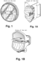
- vehicle headlights with more than one function and with an indirect projection reflector system have a configuration provided with a reflector and an LED, or a set of LEDs, dedicated to each function, that is, each reflector has its specific project for the function to be fulfilled, as we can analyze in Figures 1, 1A and 1B .
- the headlights have two reflectors, each with its set (more than 1) of LEDs, so that the reflectors work together, that is, the low beam or high beam function is performed by the set of two reflectors, and never individually.
- the electronic board fastening system is performed using a screw or glue next to the housing, which generates some inconveniences in the assembly process due to the difficulty of positioning and alignment, since the optical assembly needs to be well positioned in relation to the board so that the headlight has the necessary efficiency.
- the present inventor seeking to solve the inconveniences of the market, developed a compact constructive form provided with a single reflector that allows to meet the high and low beam functions.
- it has a system of easy fitting and positioning of the board next to the reflector, which prevents failures and increases efficiency in the assembly process.
- Document JP2018137125 also discloses a vehicular lamp made with a reduced number of components and a simpler assembling process.
- the vehicular lamp comprises: a light source; a board having the light source mounted on one surface side; a heat sink; and a reflector. Further vehicular lamp is known from US2014347875 A1 .
- the present inventor seeking to improve and perfect vehicle headlights, developed a new compact constructive form, of reduced dimensional, which allows to fulfill the high and low beam functions without any additional component, through a single reflector assembled together with an electronic circuit provided with LEDs.
- the object of this invention is a structural arrangement in a vehicle headlight that comprises a compact headlight, composed of an electronic circuit, with a set of LEDs, mounted close together and using a single indirect projection reflector to serve more than one function, in this case the low beam and high beam functions without any additional components.
- This new constructive form makes it possible for the LEDs to work interchangeably, that is, while one is on, the other is off, so that when one of the LEDs is activated, it serves the low beam function, and the other LED, when activated, serves the high beam function.
- the set has a system for easy fitting and positioning of the electronic board next to the reflector through pins and towers, ensuring quick assembly and correct positioning between the components.
- a characteristic of the invention is a structural arrangement in a vehicle headlight that provides a board with a pair of holes, a pair of smaller-sized holes and LEDs positioned in the central portion between the holes.
- a characteristic of the invention is a structural arrangement in vehicle headlight that provides a board that is positioned next to the recess of the reflector through the fitting of the holes next to the towers and pins next to the holes.
- a characteristic of the invention is a structural arrangement in a vehicle headlight that provides a reflector provided with the board positioned next to the housing through the fitting of the towers together with the channels and fixed by screws positioned in the upper portion of the housing and connected together with the towers.
- a characteristic of the invention is a structural arrangement in a vehicle headlight that provides a board positioned between the housing shoulder and the reflector recess so that its fixation occurs by tightening pressure through the screws.
- a characteristic of the invention is a structural arrangement in vehicle headlight that provides that the positioning pins and the towers allow to properly position the board in relation to the reflector and at the same time the fixation and thermal dissipation through the housing.
- the structural arrangement in vehicle headlight object of the present invention comprises a housing (10) that internally receives a reflector (20) interconnected to an LED board (30) and a translucent closing lens (40).
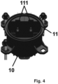
- the housing (10), of circular shape, is provided internally with a smooth-faced shoulder (11) provided with channels (111) that allow the positioning and locking of the reflector (20).
- This quick assembly and fastening system between the board (30), reflector (20) and housing (10) ensures the correct positioning between the components.
- this assembly system contributes to the thermal dissipation of the board (30), as it is in direct contact with the housing (10) which is in contact with the external environment, favoring thermal exchange.
Landscapes
- Engineering & Computer Science (AREA)
- General Engineering & Computer Science (AREA)
- Physics & Mathematics (AREA)
- Microelectronics & Electronic Packaging (AREA)
- Optics & Photonics (AREA)
- Mechanical Engineering (AREA)
- Non-Portable Lighting Devices Or Systems Thereof (AREA)
- Lighting Device Outwards From Vehicle And Optical Signal (AREA)
Description
- The present invention describes a structural arrangement in a vehicle headlight. More specifically, it comprises a compact headlight, composed of an electronic circuit, with a set of LEDs, mounted close together and using a single indirect projection reflector to serve more than one function, in this case the low and high beam functions without any additional components.
- This new constructive form makes it possible for the LEDs to work interchangeably, that is, while one is on, the other is off, so that when one of the LEDs is activated, it serves the low beam function, and the other LED, when activated, serves the high beam function.
- In addition, this constructive form makes it possible for the LEDs to work in a combined way, if it is necessary to meet a specification or a specific need of the user or market segment.
- The constant technological advance provides the electronic components industry with the development of increasingly compact items with technical specifications equal to or even superior to previous versions. Among them, we can highlight LEDs, which over the years are getting smaller, with a smaller light-emitting area, but with greater power and less thermal heating (heat generation).
- Currently, vehicle headlights with more than one function and with an indirect projection reflector system have a configuration provided with a reflector and an LED, or a set of LEDs, dedicated to each function, that is, each reflector has its specific project for the function to be fulfilled, as we can analyze in
Figures 1, 1A and 1B . - In other cases, the headlights have two reflectors, each with its set (more than 1) of LEDs, so that the reflectors work together, that is, the low beam or high beam function is performed by the set of two reflectors, and never individually.
- Thus, the current constructive form applied to vehicle headlights results in a larger product and, consequently, higher cost due to the greater amount of material and components involved.
- In addition, the electronic board fastening system is performed using a screw or glue next to the housing, which generates some inconveniences in the assembly process due to the difficulty of positioning and alignment, since the optical assembly needs to be well positioned in relation to the board so that the headlight has the necessary efficiency.
- Thus, the present inventor, seeking to solve the inconveniences of the market, developed a compact constructive form provided with a single reflector that allows to meet the high and low beam functions. In addition, it has a system of easy fitting and positioning of the board next to the reflector, which prevents failures and increases efficiency in the assembly process.
- In research carried out in the state of the art, we identified several documents that claim constructive forms applied to vehicle headlights, where we can highlight the following documents:
DocumentsBR202013017528-0 BR202015003424-0 BR202015003427-5 - Document
EP2906444 (Rebo. 20120) describes a vehicle headlight system having a headlight module and a processor. The beacon module may include a light source and a reflector. The light source may include a plurality of light emitters which may be individually controlled by the processor. The reflector may include a plurality of facets to reflect light received from the light source. The headlight module is capable of switching between high and low beam without mechanically moving components. - This document cited in the state of the art describes a headlight that allows switching between high and low, but this headlight has a complex constructivity that uses a processor to change this light beam, in addition to describing the curve light functions, which leads to a greater number of components. On the other hand, the product claimed by the present inventor does not use the processor, so the switching between the high and low function is performed by energizing the connector pins. In addition, the product does not perform other functions, thus being dedicated only to switching the beam of light between high and low, resulting in a compact and much more efficient headlight.
- Document
JP2018137125 US2014347875 A1 . - Therefore, the present inventor, seeking to improve and perfect vehicle headlights, developed a new compact constructive form, of reduced dimensional, which allows to fulfill the high and low beam functions without any additional component, through a single reflector assembled together with an electronic circuit provided with LEDs.
- Therefore, the object of this invention is a structural arrangement in a vehicle headlight that comprises a compact headlight, composed of an electronic circuit, with a set of LEDs, mounted close together and using a single indirect projection reflector to serve more than one function, in this case the low beam and high beam functions without any additional components. This new constructive form makes it possible for the LEDs to work interchangeably, that is, while one is on, the other is off, so that when one of the LEDs is activated, it serves the low beam function, and the other LED, when activated, serves the high beam function. In addition, the set has a system for easy fitting and positioning of the electronic board next to the reflector through pins and towers, ensuring quick assembly and correct positioning between the components.
- Such characteristics allow for a product with reduced dimensions and with greater efficiency in switching between high and low beams, when compared to the documents of the state of the art.
- A characteristic of the invention is a structural arrangement in a vehicle headlight that provides a circular-shaped housing, internally provided with a smooth-faced shoulder provided with channels for positioning and locking the reflector.
- A characteristic of the invention is a structural
arrangement in vehicle headlight that provides a reflector that presents a concave faceted body provided in its upper portion with a smooth-faced recess that presents fixing towers, positioning pins and an opening for the LEDs. - A characteristic of the invention is a structural
arrangement in a vehicle headlight that provides a board with a pair of holes, a pair of smaller-sized holes and LEDs positioned in the central portion between the holes. - A characteristic of the invention is a structural
arrangement in vehicle headlight that provides a board that is positioned next to the recess of the reflector through the fitting of the holes next to the towers and pins next to the holes. - A characteristic of the invention is a structural
arrangement in a vehicle headlight that provides a reflector provided with the board positioned next to the housing through the fitting of the towers together with the channels and fixed by screws positioned in the upper portion of the housing and connected together with the towers. - A characteristic of the invention is a structural
arrangement in a vehicle headlight that provides a board positioned between the housing shoulder and the reflector recess so that its fixation occurs by tightening pressure through the screws. - A characteristic of the invention is a structural
arrangement in vehicle headlight that provides that the positioning pins and the towers allow to properly position the board in relation to the reflector and at the same time the fixation and thermal dissipation through the housing. - A characteristic of the invention is a structural
arrangement in a vehicle headlight that provides a housing with a single reflector interconnected with a board and indirect projection LEDs to meet the high and low function. -
-
Figures 1, 1A and 1B are the views of vehicle headlights with more than one function and with an indirect projection reflector system, currently used in the state of the art. -
Figure 2 is an exploded perspective view of the vehicle headlight, detailing its internal components and fastening means. -
Figure 3 is an exploded perspective view of the vehicle headlight, detailing the electronic board fitted and perfectly positioned in the reflector through the pins. -
Figure 4 is a perspective view of the housing, detailing the shoulder and channels for positioning and fixing the reflector. -
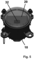
Figure 5 is a perspective view of the assembled headlight, detailing the positioning of the LED board next to the reflector. -
Figure 6 is a front view of the assembled headlight andFigure 6A is a sectional view of the headlight, detailing the positioning of the LED board next to the reflector. -
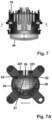
Figure 7 is a top view of the headlight andFigure 7A is a sectional view detailing the fastening means between the housing, board and reflector, demonstrating the positioning of the LED board. - The structural arrangement in vehicle headlight object of the present invention comprises a housing (10)
that internally receives a reflector (20) interconnected to an LED board (30) and a translucent closing lens (40). - The housing (10), of circular shape, is provided internally with a smooth-faced shoulder (11) provided with channels (111) that allow the positioning and locking of the reflector (20).
- The reflector (20) has a faceted concave body provided in its upper portion with a smooth-faced recess (21) that has fixing towers (22), positioning pins (211) of the board in the reflector and an opening (23) that enables the emission of light beams on the faceted structure of the reflector.
- The positioning pins (211) and the towers (22) ensure the perfect positioning of the board (30) in relation to the reflector (20) and at the same time the fixation and thermal dissipation through the housing (10).
- The board (30) is provided with a pair of holes (31), a pair of holes (311) of smaller dimension and LEDs (32) positioned in the central portion between the holes (31), so that the board (30) is positioned next to the recess (21) of the reflector through the fitting of the holes (31) together with the towers (22) and pins (211) together with the holes (311), allowing the positioning of the LEDs (32) next to the drilling (23) of the reflector (20).
- The reflector (20) provided with the board (30) is then positioned next to the housing (10) through the fitting of the towers (22) together with the channels (111), so that after fitting, the assembly is fixed by screws (221) positioned in the upper portion of the housing (10) and connected together with the towers (22).
- The board (30) is positioned between the shoulder (11) of the housing (10) and the recess (21) of the reflector (20) so that its fixation occurs by tightening pressure through the screws (221).
- The board (30) is positioned precisely through the holes (31) and the towers (22), which ensures greater efficiency and minimizes errors in the assembly of the product, in addition to ensuring the perfect alignment that ensures the optics and photometry.
- This quick assembly and fastening system between the board (30), reflector (20) and housing (10) ensures the correct positioning between the components. In addition, this assembly system contributes to the thermal dissipation of the board (30), as it is in direct contact with the housing (10) which is in contact with the external environment, favoring thermal exchange.
Claims (3)
- A STRUCTURAL ARRANGEMENT IN VEHICLE HEADLIGHT comprising a housing (10), of circular shape, internally provided with a smooth-faced shoulder (11) provided with channels (111) for positioning and locking the reflector (20) which has a faceted concave body provided in its upper portion with a smooth-faced recess (21) that has fixing towers (22), positioning pins (211) of the board (30) and an opening (23) for the LEDs, said board (30) being provided with a pair of holes (31), a pair of holes (311) of smaller dimension and LEDs (32) positioned in the central portion between the holes (31), so that the board (30) is positioned next to the recess (21) of the reflector by fitting the holes (31) together with the towers (22) and the positioning pins (211; together with the holes of smaller dimension (311); the reflector (20) provided with the board (30) is positioned next to the housing (10) through the fitting of the towers (22) together with the channels (111) and fixed by screws (221) positioned in the upper portion of the housing (10) and connected together with the towers (22); the board (30) is positioned between the shoulder (11) of the housing (10) and the recess (21) of the reflector (20) so that its fixation occurs by tightening pressure through the screws (221).
- STRUCTURAL ARRANGEMENT IN VEHICLE HEADLIGHT, according to claim 1, wherein the positioning pins (211) and the towers (22) properly position the board (30) in relation to the reflector (20) and at the same time enable the fixation and thermal dissipation through the housing (10).
- STRUCTURAL ARRANGEMENT IN VEHICLE HEADLIGHT, according to any one of the previous claims, wherein it comprises the housing (10) provided with the single reflector (20) interconnected with the board (30) and LEDs (32) of indirect projection to meet the high and low functions.
Applications Claiming Priority (2)
| Application Number | Priority Date | Filing Date | Title |
|---|---|---|---|
| BR202020024178-3U BR202020024178Y1 (en) | 2020-11-26 | 2020-11-26 | Constructive arrangement in vehicle headlights |
| PCT/BR2021/050518 WO2022109703A1 (en) | 2020-11-26 | 2021-11-25 | Structural arrangement applied to a vehicle headlamp |
Publications (4)
| Publication Number | Publication Date |
|---|---|
| EP4067168A1 EP4067168A1 (en) | 2022-10-05 |
| EP4067168A4 EP4067168A4 (en) | 2022-11-16 |
| EP4067168B1 true EP4067168B1 (en) | 2025-06-25 |
| EP4067168C0 EP4067168C0 (en) | 2025-06-25 |
Family
ID=75243234
Family Applications (1)
| Application Number | Title | Priority Date | Filing Date |
|---|---|---|---|
| EP21895975.7A Active EP4067168B1 (en) | 2020-11-26 | 2021-11-25 | Structural arrangement applied to a vehicle headlamp |
Country Status (3)
| Country | Link |
|---|---|
| EP (1) | EP4067168B1 (en) |
| BR (1) | BR202020024178Y1 (en) |
| WO (1) | WO2022109703A1 (en) |
Families Citing this family (1)
| Publication number | Priority date | Publication date | Assignee | Title |
|---|---|---|---|---|
| WO2025217694A1 (en) * | 2024-04-17 | 2025-10-23 | Balbinot Mauricio | System for integrating the luminous intensity of a vehicle light and respective vehicle light |
Family Cites Families (9)
| Publication number | Priority date | Publication date | Assignee | Title |
|---|---|---|---|---|
| US8950912B2 (en) | 2012-10-10 | 2015-02-10 | Federal-Mogul Corporation | Low and high beam headlamp |
| TWM464599U (en) * | 2013-05-24 | 2013-11-01 | Sun Yujing Technology Ltd | Vehicle LED lamp capable of improving heat dissipation effect |
| AT514403B1 (en) * | 2013-05-29 | 2015-06-15 | Zizala Lichtsysteme Gmbh | Lighting device for a vehicle headlight and vehicle headlights |
| BR202015003427Y1 (en) * | 2015-02-13 | 2021-12-07 | Mauricio Balbinot | CONSTRUCTION LAYOUT IN MODULAR HEADLIGHT APPLIED IN VEHICLES |
| CN106287488B (en) * | 2016-09-17 | 2018-10-02 | 常州星宇车灯股份有限公司 | Adjustable LED distance-light module |
| DE102016120431A1 (en) * | 2016-10-26 | 2018-04-26 | HELLA GmbH & Co. KGaA | Light module for a lighting device of a vehicle |
| JP6814069B2 (en) * | 2017-02-22 | 2021-01-13 | スタンレー電気株式会社 | Vehicle lighting |
| WO2019243246A1 (en) * | 2018-06-19 | 2019-12-26 | Lumileds Holding B.V. | Operating a lighting module with led elements |
| US10704759B1 (en) * | 2020-01-14 | 2020-07-07 | Ching-Tsung Lai | Fog lamp apparatus |
-
2020
- 2020-11-26 BR BR202020024178-3U patent/BR202020024178Y1/en active IP Right Grant
-
2021
- 2021-11-25 WO PCT/BR2021/050518 patent/WO2022109703A1/en not_active Ceased
- 2021-11-25 EP EP21895975.7A patent/EP4067168B1/en active Active
Also Published As
| Publication number | Publication date |
|---|---|
| BR202020024178Y1 (en) | 2022-04-05 |
| EP4067168A4 (en) | 2022-11-16 |
| BR202020024178U2 (en) | 2021-03-16 |
| EP4067168C0 (en) | 2025-06-25 |
| WO2022109703A1 (en) | 2022-06-02 |
| EP4067168A1 (en) | 2022-10-05 |
Similar Documents
| Publication | Publication Date | Title |
|---|---|---|
| US9803825B2 (en) | Lighting device for a vehicle headlight | |
| CN1644978B (en) | lamps | |
| US8950917B2 (en) | Vehicular lamp | |
| US20110286231A1 (en) | Vehicle lighting device | |
| US20070070645A1 (en) | LED lamp with direct optical coupling in axial arrangement | |
| JP4952613B2 (en) | Vehicle lighting | |
| KR20220044798A (en) | Vehicle lamp module, vehicle lamp and vehicle | |
| JP2010073428A (en) | Lighting fixture for vehicle | |
| CN211821815U (en) | Lamp unit | |
| JP6202288B2 (en) | Automotive lighting module | |
| EP4067168B1 (en) | Structural arrangement applied to a vehicle headlamp | |
| CN109073182B (en) | Lighting units and lamps for vehicles | |
| US20170336044A1 (en) | Lamp for vehicle | |
| JP4835605B2 (en) | Vehicle lighting | |
| CN113939685B (en) | Lighting unit for a motor vehicle having a reflector, a printed circuit board and a heat sink | |
| JP2020119634A (en) | Lighting fixture | |
| JP2009199780A (en) | Lighting fixture for vehicle | |
| JP2010073429A (en) | Lighting fixture for vehicle | |
| JP7042926B2 (en) | Vehicle lighting | |
| JP7280104B2 (en) | lighting unit | |
| CN107420755A (en) | Light source module group, illuminating lamp and its application | |
| JP2010073430A (en) | Lighting fixture for vehicle | |
| US10767832B2 (en) | Light source module for vehicle | |
| KR101851001B1 (en) | Lighting apparatus for an automobile | |
| CN221881191U (en) | Lighting device |
Legal Events
| Date | Code | Title | Description |
|---|---|---|---|
| STAA | Information on the status of an ep patent application or granted ep patent |
Free format text: STATUS: THE INTERNATIONAL PUBLICATION HAS BEEN MADE |
|
| PUAI | Public reference made under article 153(3) epc to a published international application that has entered the european phase |
Free format text: ORIGINAL CODE: 0009012 |
|
| STAA | Information on the status of an ep patent application or granted ep patent |
Free format text: STATUS: REQUEST FOR EXAMINATION WAS MADE |
|
| 17P | Request for examination filed |
Effective date: 20220628 |
|
| AK | Designated contracting states |
Kind code of ref document: A1 Designated state(s): AL AT BE BG CH CY CZ DE DK EE ES FI FR GB GR HR HU IE IS IT LI LT LU LV MC MK MT NL NO PL PT RO RS SE SI SK SM TR |
|
| A4 | Supplementary search report drawn up and despatched |
Effective date: 20221014 |
|
| RIC1 | Information provided on ipc code assigned before grant |
Ipc: F21W 102/13 20180101ALN20221007BHEP Ipc: F21S 45/48 20180101ALI20221007BHEP Ipc: F21S 41/39 20180101ALI20221007BHEP Ipc: F21S 41/33 20180101ALI20221007BHEP Ipc: F21S 41/19 20180101ALI20221007BHEP Ipc: F21S 41/148 20180101ALI20221007BHEP Ipc: B60Q 1/14 20060101ALI20221007BHEP Ipc: B60Q 1/04 20060101AFI20221007BHEP |
|
| DAV | Request for validation of the european patent (deleted) | ||
| DAX | Request for extension of the european patent (deleted) | ||
| GRAP | Despatch of communication of intention to grant a patent |
Free format text: ORIGINAL CODE: EPIDOSNIGR1 |
|
| STAA | Information on the status of an ep patent application or granted ep patent |
Free format text: STATUS: GRANT OF PATENT IS INTENDED |
|
| RIC1 | Information provided on ipc code assigned before grant |
Ipc: F21W 102/155 20180101ALN20250122BHEP Ipc: B60Q 1/068 20060101ALN20250122BHEP Ipc: F21W 102/13 20180101ALN20250122BHEP Ipc: F21S 45/48 20180101ALI20250122BHEP Ipc: F21S 41/39 20180101ALI20250122BHEP Ipc: F21S 41/33 20180101ALI20250122BHEP Ipc: F21S 41/19 20180101ALI20250122BHEP Ipc: F21S 41/148 20180101ALI20250122BHEP Ipc: B60Q 1/14 20060101ALI20250122BHEP Ipc: B60Q 1/04 20060101AFI20250122BHEP |
|
| RIC1 | Information provided on ipc code assigned before grant |
Ipc: F21W 102/155 20180101ALN20250205BHEP Ipc: B60Q 1/068 20060101ALN20250205BHEP Ipc: F21W 102/13 20180101ALN20250205BHEP Ipc: F21S 45/48 20180101ALI20250205BHEP Ipc: F21S 41/39 20180101ALI20250205BHEP Ipc: F21S 41/33 20180101ALI20250205BHEP Ipc: F21S 41/19 20180101ALI20250205BHEP Ipc: F21S 41/148 20180101ALI20250205BHEP Ipc: B60Q 1/14 20060101ALI20250205BHEP Ipc: B60Q 1/04 20060101AFI20250205BHEP |
|
| INTG | Intention to grant announced |
Effective date: 20250217 |
|
| GRAS | Grant fee paid |
Free format text: ORIGINAL CODE: EPIDOSNIGR3 |
|
| GRAA | (expected) grant |
Free format text: ORIGINAL CODE: 0009210 |
|
| STAA | Information on the status of an ep patent application or granted ep patent |
Free format text: STATUS: THE PATENT HAS BEEN GRANTED |
|
| AK | Designated contracting states |
Kind code of ref document: B1 Designated state(s): AL AT BE BG CH CY CZ DE DK EE ES FI FR GB GR HR HU IE IS IT LI LT LU LV MC MK MT NL NO PL PT RO RS SE SI SK SM TR |
|
| REG | Reference to a national code |
Ref country code: GB Ref legal event code: FG4D |
|
| REG | Reference to a national code |
Ref country code: CH Ref legal event code: EP |
|
| REG | Reference to a national code |
Ref country code: CH Ref legal event code: EP |
|
| REG | Reference to a national code |
Ref country code: IE Ref legal event code: FG4D |
|
| U01 | Request for unitary effect filed |
Effective date: 20250630 |
|
| U07 | Unitary effect registered |
Designated state(s): AT BE BG DE DK EE FI FR IT LT LU LV MT NL PT RO SE SI Effective date: 20250704 |
|
| PG25 | Lapsed in a contracting state [announced via postgrant information from national office to epo] |
Ref country code: NO Free format text: LAPSE BECAUSE OF FAILURE TO SUBMIT A TRANSLATION OF THE DESCRIPTION OR TO PAY THE FEE WITHIN THE PRESCRIBED TIME-LIMIT Effective date: 20250925 Ref country code: GR Free format text: LAPSE BECAUSE OF FAILURE TO SUBMIT A TRANSLATION OF THE DESCRIPTION OR TO PAY THE FEE WITHIN THE PRESCRIBED TIME-LIMIT Effective date: 20250926 |
|
| PG25 | Lapsed in a contracting state [announced via postgrant information from national office to epo] |
Ref country code: HR Free format text: LAPSE BECAUSE OF FAILURE TO SUBMIT A TRANSLATION OF THE DESCRIPTION OR TO PAY THE FEE WITHIN THE PRESCRIBED TIME-LIMIT Effective date: 20250625 |
|
| PG25 | Lapsed in a contracting state [announced via postgrant information from national office to epo] |
Ref country code: RS Free format text: LAPSE BECAUSE OF FAILURE TO SUBMIT A TRANSLATION OF THE DESCRIPTION OR TO PAY THE FEE WITHIN THE PRESCRIBED TIME-LIMIT Effective date: 20250925 |
|
| U20 | Renewal fee for the european patent with unitary effect paid |
Year of fee payment: 5 Effective date: 20251002 |
|
| PG25 | Lapsed in a contracting state [announced via postgrant information from national office to epo] |
Ref country code: IS Free format text: LAPSE BECAUSE OF FAILURE TO SUBMIT A TRANSLATION OF THE DESCRIPTION OR TO PAY THE FEE WITHIN THE PRESCRIBED TIME-LIMIT Effective date: 20251025 |
|
| PG25 | Lapsed in a contracting state [announced via postgrant information from national office to epo] |
Ref country code: SM Free format text: LAPSE BECAUSE OF FAILURE TO SUBMIT A TRANSLATION OF THE DESCRIPTION OR TO PAY THE FEE WITHIN THE PRESCRIBED TIME-LIMIT Effective date: 20250625 |
|
| PG25 | Lapsed in a contracting state [announced via postgrant information from national office to epo] |
Ref country code: CZ Free format text: LAPSE BECAUSE OF FAILURE TO SUBMIT A TRANSLATION OF THE DESCRIPTION OR TO PAY THE FEE WITHIN THE PRESCRIBED TIME-LIMIT Effective date: 20250625 |
|
| PG25 | Lapsed in a contracting state [announced via postgrant information from national office to epo] |
Ref country code: PL Free format text: LAPSE BECAUSE OF FAILURE TO SUBMIT A TRANSLATION OF THE DESCRIPTION OR TO PAY THE FEE WITHIN THE PRESCRIBED TIME-LIMIT Effective date: 20250625 |
|
| PG25 | Lapsed in a contracting state [announced via postgrant information from national office to epo] |
Ref country code: SK Free format text: LAPSE BECAUSE OF FAILURE TO SUBMIT A TRANSLATION OF THE DESCRIPTION OR TO PAY THE FEE WITHIN THE PRESCRIBED TIME-LIMIT Effective date: 20250625 |
|
| PG25 | Lapsed in a contracting state [announced via postgrant information from national office to epo] |
Ref country code: ES Free format text: LAPSE BECAUSE OF FAILURE TO SUBMIT A TRANSLATION OF THE DESCRIPTION OR TO PAY THE FEE WITHIN THE PRESCRIBED TIME-LIMIT Effective date: 20250625 |
|
| PLBE | No opposition filed within time limit |
Free format text: ORIGINAL CODE: 0009261 |
|
| STAA | Information on the status of an ep patent application or granted ep patent |
Free format text: STATUS: NO OPPOSITION FILED WITHIN TIME LIMIT |