EP4067098A2 - Head unit, head unit adjustment method, attaching/detaching jig and head unit exchange method - Google Patents
Head unit, head unit adjustment method, attaching/detaching jig and head unit exchange method Download PDFInfo
- Publication number
- EP4067098A2 EP4067098A2 EP22159992.1A EP22159992A EP4067098A2 EP 4067098 A2 EP4067098 A2 EP 4067098A2 EP 22159992 A EP22159992 A EP 22159992A EP 4067098 A2 EP4067098 A2 EP 4067098A2
- Authority
- EP
- European Patent Office
- Prior art keywords
- head
- head unit
- holder
- ink discharge
- base member
- Prior art date
- Legal status (The legal status is an assumption and is not a legal conclusion. Google has not performed a legal analysis and makes no representation as to the accuracy of the status listed.)
- Granted
Links
Images







Classifications
-
- B—PERFORMING OPERATIONS; TRANSPORTING
- B41—PRINTING; LINING MACHINES; TYPEWRITERS; STAMPS
- B41J—TYPEWRITERS; SELECTIVE PRINTING MECHANISMS, i.e. MECHANISMS PRINTING OTHERWISE THAN FROM A FORME; CORRECTION OF TYPOGRAPHICAL ERRORS
- B41J25/00—Actions or mechanisms not otherwise provided for
- B41J25/001—Mechanisms for bodily moving print heads or carriages parallel to the paper surface
-
- B—PERFORMING OPERATIONS; TRANSPORTING
- B41—PRINTING; LINING MACHINES; TYPEWRITERS; STAMPS
- B41J—TYPEWRITERS; SELECTIVE PRINTING MECHANISMS, i.e. MECHANISMS PRINTING OTHERWISE THAN FROM A FORME; CORRECTION OF TYPOGRAPHICAL ERRORS
- B41J25/00—Actions or mechanisms not otherwise provided for
- B41J25/304—Bodily-movable mechanisms for print heads or carriages movable towards or from paper surface
- B41J25/316—Bodily-movable mechanisms for print heads or carriages movable towards or from paper surface with tilting motion mechanisms relative to paper surface
-
- B—PERFORMING OPERATIONS; TRANSPORTING
- B41—PRINTING; LINING MACHINES; TYPEWRITERS; STAMPS
- B41J—TYPEWRITERS; SELECTIVE PRINTING MECHANISMS, i.e. MECHANISMS PRINTING OTHERWISE THAN FROM A FORME; CORRECTION OF TYPOGRAPHICAL ERRORS
- B41J25/00—Actions or mechanisms not otherwise provided for
- B41J25/304—Bodily-movable mechanisms for print heads or carriages movable towards or from paper surface
-
- B—PERFORMING OPERATIONS; TRANSPORTING
- B41—PRINTING; LINING MACHINES; TYPEWRITERS; STAMPS
- B41J—TYPEWRITERS; SELECTIVE PRINTING MECHANISMS, i.e. MECHANISMS PRINTING OTHERWISE THAN FROM A FORME; CORRECTION OF TYPOGRAPHICAL ERRORS
- B41J25/00—Actions or mechanisms not otherwise provided for
- B41J25/304—Bodily-movable mechanisms for print heads or carriages movable towards or from paper surface
- B41J25/308—Bodily-movable mechanisms for print heads or carriages movable towards or from paper surface with print gap adjustment mechanisms
- B41J25/3086—Bodily-movable mechanisms for print heads or carriages movable towards or from paper surface with print gap adjustment mechanisms with print gap adjustment means between the print head and its carriage
-
- B—PERFORMING OPERATIONS; TRANSPORTING
- B41—PRINTING; LINING MACHINES; TYPEWRITERS; STAMPS
- B41J—TYPEWRITERS; SELECTIVE PRINTING MECHANISMS, i.e. MECHANISMS PRINTING OTHERWISE THAN FROM A FORME; CORRECTION OF TYPOGRAPHICAL ERRORS
- B41J25/00—Actions or mechanisms not otherwise provided for
- B41J25/34—Bodily-changeable print heads or carriages
-
- B—PERFORMING OPERATIONS; TRANSPORTING
- B41—PRINTING; LINING MACHINES; TYPEWRITERS; STAMPS
- B41J—TYPEWRITERS; SELECTIVE PRINTING MECHANISMS, i.e. MECHANISMS PRINTING OTHERWISE THAN FROM A FORME; CORRECTION OF TYPOGRAPHICAL ERRORS
- B41J2202/00—Embodiments of or processes related to ink-jet or thermal heads
- B41J2202/01—Embodiments of or processes related to ink-jet heads
- B41J2202/21—Line printing
Definitions
- This invention relates to a head unit to be detachably arrayed in a predetermined array direction with respect to a base member, and an adjustment method, an attaching/detaching jig and an exchange method for head unit.
- a printing apparatus which prints an image on the upper surface of a printing medium by discharging a water-based or oil-based ink or the like to the printing medium from nozzle surfaces of ink discharge heads by an inkjet method.
- a plurality of fluid discharge modules are arrayed in a predetermined direction and mounted on a frame (corresponding to a "base member" of the invention). More particularly, a module mount assembly (corresponding to an "ink discharge head” of the invention) is formed by joining the fluid discharge module to a module mount. In this way, a plurality of the module mount assemblies are prepared.
- a plurality of clamp assemblies are mounted on the frame and the clamp assemblies are aligned using an alignment jig. Then, the module mount assemblies are mounted one-to-one on the clamp assemblies.
- the plurality of module mount assemblies are aligned with each other by aligning the clamp assemblies.
- the fluid discharge modules are merely joined to the module mounts and the postures and positions of the nozzle surfaces of the fluid discharge modules are not constantly aligned before mounting on the frame.
- automatic adjustment is performed, utilizing biasing forces of springs incorporated in the clamp assemblies in the apparatus of JP 6524173B .
- This invention was developed in view of the above problem and aims to provide a head unit having excellent print quality and an adjustment method, an attaching/detaching jig and an exchange method for head unit.
- a first aspect of the invention is a head unit to be detachably arrayed in a predetermined array direction on a base member, the head unit comprising: an ink discharge head having a nozzle surface configured to discharge an ink; a head holder attachable to and detachable from the base member while holding the ink discharge head in a holding region; and a posture adjustment mechanism configured to adjust a posture of the nozzle surface with respect to the head holder by rotating the ink discharge head with respect to the head holder about an axis of rotation perpendicular to both a surface normal to the nozzle surface and the array direction in a state where the head holder is not attached to the base member.
- a second aspect of the invention is a head unit to be detachably arrayed in a predetermined array direction on a base member, the head unit comprising: an ink discharge head having a nozzle surface configured to discharge an ink; a head holder attachable to and detachable from the base member while holding the ink discharge head in a holding region; and a height adjustment mechanism configured to adjust a height position of the nozzle surface with respect to the head holder by moving the ink discharge head with respect to the head holder in a height direction parallel to a surface normal to the nozzle surface in a state where the head holder is not attached to the base member.
- a third aspect of the invention is a head unit adjustment method for adjusting a head unit to be detachably arrayed in a predetermined array direction on a base member, the method comprising: (a) inserting an ink discharge head having a nozzle surface configured to discharge an ink into a holding region of a head holder; (b1) adjusting a posture of the nozzle surface with respect to the head holder by rotating the ink discharge head inserted into the holding region with respect to the head holder about an axis of rotation perpendicular to a surface normal to the nozzle surface and the array direction; and (c) fixing the ink discharge head to the head holder to form the head unit after the step (b1) is performed, the operation (a), the operation (b1) operation and the (c) operation performed before the head unit is attached to the base member.
- a fourth aspect of the invention is a head unit adjustment method for adjusting a head unit to be detachably arrayed in a predetermined array direction with respect to a base member, the method comprising: (a) inserting an ink discharge head having a nozzle surface configured to discharge an ink into a holding region of a head holder; (b2) adjusting a height position of the nozzle surface with respect to the head holder by moving the ink discharge head inserted into the holding region with respect to the head holder in a height direction parallel to a surface normal to the nozzle surface; and (c) fixing the ink discharge head to the head holder so as to form the head unit after the operation (b2) is performed, the operation (a), the operation (b1) operation and the (c) operation performed before the head unit is attached to the base member.
- a fifth aspect of the invention is an attaching/detaching jig for attaching and detaching a plurality of head units to be mounted side by side in an array direction on a base member one by one to and from the base member, the jig comprising: a jig body including a guide member extending in a sliding direction orthogonal to the array direction, the jig body being attachable to and detachable from the base member; and a slider supported movably in the sliding direction along the guide member while supporting the head unit.
- a sixth aspect of the invention is a head unit exchange method for exchanging a first head unit to a second head unit, out of a plurality of head units mounted side by side in an array direction on a base member, the method comprising: attaching the jib body to the base member such that the slider of the attaching/detaching jig faces the first head unit; supporting the first head unit by the slider; moving the slider supporting the first head unit to a separated position separated from the base member in the sliding direction; placing the second head unit on the slider after the first head unit is removed from the slider at the separated position; locating the second head unit at an exchange position where the first head unit was mounted by moving the slider supporting the second head unit to the base member; and attaching the second head unit to the base member at the exchange position and removing the attaching/detaching jig from the base member.
- the posture and height position of the nozzle surface with respect to the head holder can be adjusted in the head unit in the unattached state where the head unit is not attached to the base member, and excellent print quality is obtained.
- the above adjusted head unit can be stably attached to and detached from the base member, excellent print quality is obtained also in a state where the head unit is attached to the base member.
- All of a plurality of constituent elements of each aspect of the invention described above are not essential and some of the plurality of constituent elements can be appropriately changed, deleted, replaced by other new constituent elements or have limited contents partially deleted in order to solve some or all of the aforementioned problems or to achieve some or all of effects described in this specification. Further, some or all of technical features included in one aspect of the invention described above can be combined with some or all of technical features included in another aspect of the invention described above to obtain one independent form of the invention in order to solve some or all of the aforementioned problems or to achieve some or all of the effects described in this specification.
- FIG. 1 is a front view schematically showing an example of a printing system equipped with one embodiment of a head unit according to the invention.
- a horizontal direction in which a coating apparatus 2, a printing apparatus 3 and a drying apparatus 4 constituting a printing system 1 are arranged is referred to as an "X direction”
- a horizontal direction from a right side toward a left side of FIG. 1 is referred to as a "+X direction”
- an opposite direction is referred to as a "-X direction” to clarify an arrangement relationship of each component of the apparatus.
- a direction forward of the apparatuses is referred to as a "+Y direction” and a direction backward of the apparatuses is referred to as a "-Y direction”.
- upward and downward directions along a vertical direction Z are respectively referred to as a "+Z direction” and a "-Z direction”.
- This printing system 1 applies a coating process, a printing process and a drying process to a printing medium M while conveying the printing medium M in the form of a long strip from a feeding roll 11 to a winding roll 12 in a roll-to-roll manner by controlling each component of the apparatuses by a controller 100. That is, the coating apparatus 2 applies a coating liquid to the printing medium M. Then, the printing apparatus 3 prints an image by causing various inks to adhere to the printing medium M in an ink-jet method. Further, the drying apparatus 4 dries the inks adhering to the printing medium M.
- a material of the printing medium M is a film made of OPP (oriented polypropylene), PET (polyethylene terephthalate) or the like.
- the material of the printing medium M is not limited to the film and may be paper or the like. Such a printing medium M is flexible. Further, out of both surfaces of the printing medium M, the surface on which images are to be printed is referred to as a front surface M1 and the surface opposite to the front surface M1 is referred to as a back surface M2 as appropriate.
- the coating apparatus 2 includes a pan 21 storing a liquid primer (coating liquid), a gravure roller 22 partially immersed in the primer stored in the pan 21 and a conveying unit 23 conveying the printing medium M.
- a coating region is provided where the gravure roller 22 contacts the printing medium M conveyed by the conveying unit 23 from below, and the conveying unit 23 conveys the printing medium M along the coating region with the front surface M1 of the printing medium M facing down.
- the gravure roller 22 supplies the primer to the coating region by rotating while holding the primer on the peripheral surface thereof. In this way, the primer supplied by the gravure roller 22 is applied to the front surface M1 of the printing medium M in the coating region.
- a moving direction of the printing medium M and a rotating direction of the peripheral surface of the gravure roller 22 are opposite. That is, the primer is applied to the printing medium M by a reverse kiss method. Then, the conveying unit 23 carries out the printing medium M from the coating apparatus 2 to the printing apparatus 3 with the front surface M1 of the printing medium M having the primer applied thereto facing up.
- the printing apparatus 3 includes a housing 31, a color printing unit 32 arranged in the housing 31, a white printing unit 33 arranged above the color printing unit 32 in the housing 31, and a conveying unit 34 conveying the printing medium M by a plurality of rollers arranged in the housing 31.
- the color printing unit 32 includes a plurality of (four) printing bar units 321 arrayed in the moving direction (direction from the other side X2 toward the one side X1) of the printing medium M above the printing medium M conveyed by the conveying unit 34.
- the plurality of printing bar units 321 include nozzles facing the front surface M1 of the printing medium M passing therebelow from above, and discharge color inks of mutually different colors from the nozzles by the ink-jet method.
- the color inks mean inks other than a white ink and include inks of cyan, magenta, yellow, black and the like.
- the plurality of printing bar units 321 of the color printing unit 32 print a color image on the front surface M1 of the printing medium M by discharging the color inks to the front surface M1 of the printing medium M passing therebelow from above.
- the white printer 33 includes a single printing bar unit 331 arranged above the printing medium M conveyed by the conveyor 34.
- the printing bar unit 331 includes nozzles facing the front surface M1 of the printing medium M passing therebelow and discharges a white ink from the nozzles by an inkjet method. In this way, the printing bar unit 331 of the white printer 33 prints a white image on the front surface M1 of the printing medium M by discharging the white ink to the front surface M1 of the printing medium M passing therebelow from above.
- the printing bar unit 321, 331 is composed of a plurality of ink discharge heads for discharging the ink from nozzle surfaces by an inkjet method.
- ten ink discharge heads are arranged in the width direction Y of the printing medium M. That is, the width direction Y corresponds to an "array direction" of the invention.
- the detailed configuration of the printing bar unit 321, 331 and the adjustment and exchange of each ink discharge head are described in detail later.
- two types of dryers are provided in the housing 31 of the printing apparatus 3.
- One dryer is a pre-dryer for drying the color inks adhered to the surface M1 of the printing medium M by the color printer 32.
- the other dryer is an upper dryer for drying the white ink adhered to the surface M1 of the printing medium M by the white printer 33.
- the drying apparatus 4 dries the inks adhering to the surface M1 of the printing medium M being conveyed from the printing apparatus 3.
- the drying apparatus 4 includes a housing 41 (drying furnace). Further, in the housing 41, rollers 42, 43 and 46 are arranged on a (+X) side and air turn bars 44, 45 are arranged on a (-X) side. By this arrangement, a substantially S-shaped conveyance path when viewed from a (+Y) side is configured, and the printing medium M is conveyed along this conveyance path. The inks adhering to the surface M1 of the printing medium M are dried during this conveyance. Then, the printing medium M subjected to the drying process is carried out from the drying apparatus 4 and wound on the winding roll 12.
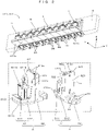
- FIG. 2 is a perspective view showing a main part of the printing bar unit.
- ten head units 6 are adjacently mounted in the array direction Y on a base member 5 extending in the array direction Y.
- each head unit 6 is such that the ink discharge head 61 is held by a head holder 62, and fixed by fixing screws 65 after a posture adjustment and a height adjustment.
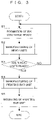
- FIG. 3 is a flow chart showing a manufacturing method of the printing bar unit shown in FIG. 2 .
- an operator performs Steps S1 to S5 shown in FIG. 3 .
- the formation of the ink discharge heads 61, the manufacturing of the head units 6 and the attachment of the head units 6 are described while the configuration of the head units 6 is described as appropriate.
- FIG. 4 is an exploded assembly perspective view of the head unit.
- FIG. 5 is a perspective view of the ink discharge head viewed from a back rear side.
- the ink discharge head 61 and the head holder 62 constituting the head unit 6 are respectively structured as follows, and the ink discharge head 61 is insertable into a holding region 62a of the head holder 62.
- the printing bar unit 321, 331 is so arranged that nozzle surfaces 611c for discharging the ink face the surface M1 ( FIG. 1 ) of the printing medium M. Accordingly, directions of a surface normal NL ( FIG. 5 ) to the nozzle surface 611c and a surface normal to the surface M1 do not constantly coincide with the vertical direction Z. However, to facilitate the understanding of the contents of the invention, description is given below, assuming that the direction of the surface normal NL substantially coincides with the vertical direction Z and the direction Z corresponds to a "height direction" of the invention.
- the ink discharge head 61 includes an ink discharge module 611 and a module mount 612.
- the ink discharge module 611 has a function to discharge the ink circulated and supplied via an ink inflow port 611a and an ink outflow port 611b downward (-Z) from the nozzle surface 611c in the form of liquid droplets as conventionally known.
- the module mount 612 includes a horizontal part 612a facing the printing medium M and a vertical part 612b standing upward from an end part in the (-X) direction of the horizontal part 612a and has a substantially L-shaped cross-sectional structure.
- the horizontal part 612a is provided with a rectangular opening (not shown) slightly narrower than the nozzle surface 611c and has a frame shape in a plan view from above.
- the ink discharge module 611 is inserted upward (+Z) via the rectangular opening with the nozzle surface 611c facing downward, the ink discharge module 611 is locked by a frame edge part of the horizontal part 612a while exposing the nozzle surface 611c downward.
- the ink discharge module 611 is fixed to the module mount 612. In this way, the ink discharge module 611 and the module mount 612 are integrated to form the ink discharge head 61 (Step S1).
- the ink discharge head 61 a pair of projecting parts 612c project in the (-X) direction on a vertical surface on a (-X) side of the vertical part 612b as shown in FIG. 5 .
- This pair of projecting parts 612c extend in the vertical direction Z and are finished into a shape fittable to the head holder 62.
- the ink discharge head 61 can be stably inserted into the holding region 62a of the head holder 62 from below.
- the ink discharge head 61 and the head holder 62 can also be integrated by moving the head holder 62 toward the ink discharge head 61 from above.
- the head holder 62 includes a holder base 620 extending in the vertical direction Z, a first holder member 621 extending in the vertical direction Z on a (-Y) side of the holder base 620 and a second holder member 622 extending in the vertical direction Z on a (+Y) side of the holder base 620.
- a region surrounded by these holder base 620, first holder member 621 and second holder member 622 corresponds to the holding region 62a, and the ink discharge head 61 can be held in this holding region 62a.
- a height adjustment mechanism 63 for adjusting a relative height position, i.e. a relative position, of the nozzle surface 611c with respect to the head holder 62 is mounted in a central lower part of the holder base 620 as shown in FIG. 4 . Further, a posture adjustment mechanism 64 for adjusting the posture of the nozzle surface 611c is mounted on the first and second holder members 621, 622.
- the height adjustment mechanism 63 includes a movable member 631 provided movably in the vertical direction Z along a side surface on a (+X) side of the holder base 620 and a round tip screw 632 functioning as a mover for moving the movable member 631 in the height direction Z.
- the movable member 631 corresponds to an example of a "fourth movable member” of the invention, and a lower end part 631a thereof is finished into a shape projecting downward.
- an upper end part 631b of the movable member 631 is finished into an inclined surface inclined with respect to the height direction Z, and higher on the (+X) side (left side of FIG. 8 ) than on a (-X) side (right side of FIG.
- the round tip screw 632 is screwed into the holder base 620 from the (-X) side, and a tip part of the round tip screw 632 advances in the (+X) direction while sliding on the inclined surface by the operator rotating the round tip screw 631 clockwise. As a result, the movable member 631 is moved downward (-Z). Conversely, the round tip screw 632 retreats in the (-X) direction by the operator rotating the round tip screw 631 counterclockwise, whereby the movable member 631 can be moved upward (+Z).
- the position of the movable member 631 in the horizontal direction Z can be controlled according to a rotation amount of the round tip screw 632 and the relative height position (relative position) of the nozzle surface 611c with respect to the head holder 62 can be adjusted at the time of manufacturing the head unit 6 to be described later.
- the posture adjustment mechanism 64 includes two movable members 641, 642 to be mounted into the first holder member 621 and one movable member 643 to be mounted into the second holder member 622. These three movable members 641 to 643 basically have the same configuration and only the mounting positions thereof are different from each other.
- the movable member 641 is composed of a ball 641a and a set screw 641b made of stainless or resin and to be inserted into a through hole 621a ( FIG. 7 ) penetrating in the Y direction at an upper position of the first holder member 621.
- the ball 641a is arranged movably in the array direction Y in the through hole 621a.
- the set screw 641b is provided movably back and forth in the array direction Y while being threadably engaged with an internal thread provided on the inner peripheral surface of the through hole 621a on a (-Y) side of the ball 641a.
- an amount (hereinafter, referred to as a projection amount) of the set screw 641b projecting from an opening on a (+Y) side of the through hole 621a toward the holding region 62a changes according to a movement of the set screw 641b. That is, a push-in amount of the ball 641a to the ink discharge head 61 located in the holding region 62a can be adjusted according to a rotation amount of the set screw 641b.
- the movable member 642 is composed of a ball 642a and a set screw 642b to be inserted into a through hole 621b ( FIG. 7 ) penetrating in the Y direction at a position separated downward from the movable member 641 (lower position of the first holder member 621).
- a projection amount of the set screw 642b projecting from an opening on a (+Y) side of the through hole 621b changes according to a movement of the set screw 642b. That is, a push-in amount of the ball 642a to the ink discharge head 61 located in the holding region 62a can be adjusted according to a rotation amount of the set screw 642b.
- the movable member 643 is composed of a ball 643a ( FIG. 7 ) and a set screw 643b to be inserted into a through hole 621c penetrating in the Y direction at a center position of the second holder member 622.
- This "center position" means a position facing an intermediate part of the first holder member 621 located between the movable members 641 and 642.
- a projection amount of the set screw 643b projecting from an opening on a (-Y) side of the through hole 621c changes according to a movement of the set screw 643b. That is, a push-in amount of the ball 643a to the ink discharge head 61 located in the holding region 62a can be adjusted according to a rotation amount of the set screw 643b.
- the posture of the nozzle surface 611c with respect to the head holder 62 can be adjusted. For example, if the projection amount of one of the movable members 641, 642 into the holding region 62a is increased and the projection amount of the other into the holding region 62a is reduced, the ink discharge head 61 can be rotated about an axis of rotation AX parallel to a direction (X direction) perpendicular to both the surface normal NL to the nozzle surface 611c and the array direction Y with respect to the head holder 62 as shown in FIG. 4 . In this way, the posture of the nozzle surface 611c can be accurately adjusted in a YZ plane.
- the ink discharge head 61 moves toward the second holder member 622 (toward +Y side).
- the ink discharge head 61 moves toward the first holder member 622 (toward -Y side). In this way, the position of the nozzle surface 611c in the array direction Y can be accurately adjusted.
- the head unit 6 is manufactured by the operator fitting the ink discharge head 61 formed in Step S1 to the thus configured head holder 62 (Step S2). The manufacturing of the head unit 6 is described below with reference to FIGS. 4 to 8 .
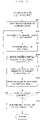
- FIG. 6 is a flow chart showing an operation procedure of manufacturing the head unit.
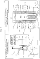
- FIG. 7 is a chart schematically showing a horizontal/rotational adjusting operation performed in the manufacturing of the head unit.
- FIG. 8 is a chart schematically showing a height adjusting operation performed in the manufacturing of the head unit.
- the ink discharge head 61 is inserted into the holding region 62a of the head holder 62 while the pair of projecting parts 612c are caused to slide in contact with the holder members 621, 622 (Step S21). In this way, the ink discharge head 61 is integrated with the head holder 62 with a certain accuracy.
- the positioning accuracy of the nozzle surface 611c with respect to the head holder 62 is not sufficient to ensure required print quality. Accordingly, in this embodiment, the positioning accuracy is enhanced by performing the horizontal/rotational adjusting operation (Steps S22 to S24) and the height adjusting device (Steps S25 to S27).
- the head unit 6 before the both adjusting operations are completed is called an "unadjusted head unit 6". Note that a sequence of the horizontal/rotational adjusting operation and the height adjusting device for the unadjusted head unit 6 is arbitrary, but the horizontal/rotational adjusting operation using the horizontal/rotational adjusting device 7 is first performed in this embodiment.
- the horizontal/rotational adjusting device 7 includes a device base 71, an imager 72, a projector 73, a light receiver 74 and a horizontal/rotational controller 75.
- a side view showing a state where the unadjusted head unit 6 is mounted on the horizontal/rotational adjusting device 7 when viewed from the X direction is shown in the field (a) of FIG. 7
- a sectional view of the unadjusted head unit 6 in a mounted state is shown in a field (b) of FIG. 7 .
- a holding mechanism (not shown) for holding the head holder 62 of the unadjusted head unit 6 at a predetermined position is provided on the device base 71, and the unadjusted head unit 6 is attachable to and detachable from the device base 71 with the nozzle surface 611 facing downward.
- the head holder 62 is positioned at a reference position.
- the imager 72, the projector 73 and the light receiver 74 are arranged below the unadjusted head unit 6 mounted on the device base 71.
- the imager 72 images the nozzle surface 611c and the periphery thereof, and outputs a signal of a captured image to the horizontal/rotational controller 75.
- the horizontal/rotational controller 75 having receiving this signal displays this image on a display (not shown) of the horizontal/rotational controller 75.
- the operator can confirm the current position of the nozzle surface 611c and the posture of the nozzle surface 611c in an XY plane by observing the image on the display.
- the projector 73 irradiates light at a certain incident angle (e.g. 45°) to the nozzle surface 611c in a YZ plane (plane of FIG. 7 ) in response to a lighting command of the horizontal/rotational controller 75.
- the light receiver 74 receives the reflected light reflected by the nozzle surface 611c and outputs information on a light reception position to the horizontal/rotational controller 75.
- the horizontal/rotational controller 75 having received this information calculates a rotation angle ⁇ 2 of the nozzle surface 611c about the axis of rotation AX parallel to the X direction based on the information on the light reception position, and displays that calculated value on the display.
- the operator can precisely grasp the rotation angle ⁇ 2 of the nozzle surface 611c by confirming a numerical value on the display.
- the operator mounts the unadjusted head unit 6 on the device base 71 as shown in FIG. 7 (Step S22). Subsequent to that, when the operator instructs the start of an adjustment to the horizontal/rotational controller 75, the entire image of the nozzle surface 611c and the value of the rotation angle ⁇ 2 of the nozzle surface 611c are displayed on the display as described above.
- Step S23 the operator grasps the current position of the nozzle surface 611c and the rotation angle ⁇ 2 of the nozzle surface 611c and performs a horizontal/rotational adjustment by advancing or retreating all or some of the set screws 6431b to 643b in the Y direction if necessary (Step S23).
- specific methods for performing the horizontal position adjustment of the nozzle surface 611c in the array direction Y and the rotational adjustment of the nozzle surface 611c about the axis of rotation AX are as already described.
- the unadjusted head unit 6 is removed from the device base 71 and a transition is made to the height adjusting operation.
- the height adjusting device 8 includes a device base 81, a length meter 82 and a height controller 83.
- a side view showing a state where the unadjusted head unit 6 is mounted on the height adjusting device 8 when viewed from the X direction is shown in the field (a) of FIG. 8
- a sectional view of the unadjusted head unit 6 in a mounted state is shown in a field (b) of FIG. 8 .
- a holding mechanism (not shown) for holding the head holder 62 of the unadjusted head unit 6 at a predetermined position is provided on the device base 81, and the unadjusted head unit 6 is attachable to and detachable from the device base 81 with the nozzle surface 611 facing downward.
- the head holder 62 is positioned at a reference position.
- the length meter 82 is arranged at a position right below the unadjusted head unit 6 mounted on the device base 81.
- the length meter 82 measures a distance to the nozzle surface 611c by irradiating light toward the nozzle surface 611c and receiving the light reflected by the nozzle surface 611c, and outputs information on this distance to the height controller 83.
- the height controller 83 having received this information calculates a height position of the nozzle surface 611c with respect to the head holder 62 in the height direction Z based on the information on the distance and displays that calculated value on a display.
- the operator can precisely grasp the height position of the nozzle surface 611c by confirming a numerical value on the display.
- the operator mounts the unadjusted head unit 6 (but already finished with the horizonal/rotational adjustment) on the device base 81 as shown in FIG. 8 (Step S25). Subsequent to that, when the operator instructs the start of an adjustment to the height controller 83, the height position of the nozzle surface 611c is displayed on the display as described above. In this way, the operator grasps the current position of the nozzle surface 611c in the height direction Z and performs the height adjustment by causing the round tip screws 632 to advance or retreat in the X direction if necessary (Step S26). Note that a specific method for performing the height adjustment of the nozzle surface 611c in the height direction Z is as already described.
- Step S27 When both the horizontal/rotational adjustment and the height adjustment are completed ("YES" in Step S27), the ink discharge head 61 is fixed to a lower end part of the head holder 62 by the fixing screws 65 ( FIG. 2 ) with the adjusted state maintained (Step S28). The operator removes the head unit 6 completed with the horizontal/rotational adjustment and the height adjustment from the device base 81, thereby completing the manufacturing of the head unit 6.
- Step S3 the operator determines whether or not the number of the adjusted head units 6 has reached the number N of the head units 6 to be attached to the base member 5 (Step S3). While the prepared number of the head units 6 is determined to be less than the number N, the operator repeats Steps S1 and S2. On the other hand, if N head units 6 completed with the horizontal/rotational adjustment and the height adjustment are prepared, the operator attaches the N head units 6 to the base member 5 to manufacture the printing bar (Step S4). An operation procedure of manufacturing the printing bar is described with reference to FIGS. 9 to 11 .
- FIG. 9 is a flow chart showing a manufacturing procedure of the printing bar unit.
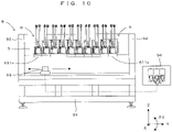
- FIG. 10 is a view showing a schematic configuration of an alignment device used in manufacturing the printing bar.
- FIG. 11 is a perspective view showing one embodiment of a head unit attaching/detaching jig according to the invention.
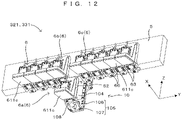
- FIG. 12 is a perspective view showing an example of the attachment of the attaching/detaching jig of FIG. 11 to the base member.
- the alignment device 9 used in manufacturing the printing bar unit includes an alignment base 91, a pair of column parts 92, 92, an imager 93 and a display unit 94 as shown in FIG. 10 .
- the pair of column parts 92, 92 stand from the upper surface of the alignment base 91 while being separated in the array direction Y.
- the imager 93 is provided movably in the array direction Y on the upper surface of the alignment base 91.
- the imager 93 is mounted to face the base member 5 from below and can capture an image of the nozzle surface 611c of the head unit 6 attached to the base member 5 and the periphery of the nozzle surface 611c as described later.
- the image captured by the imager 93 is displayed on the display unit 94.
- the adjusting/detaching jig 10 is a jig for attaching and detaching the head units 6 to and from the base member 5 one by one.
- the adjusting/detaching jig 10 includes a jig body 101 attachable to and detachable to the base member 5.
- the jig body 101 includes a pair of mounting members 103 to be mounted on the base member 5 by fasteners 102 such as bolts, and a guide member 104 extending in a sliding direction Z orthogonal to the array direction Y.
- the mounting members 103 are, for example, attached to the base member 5 to correspond to an attachment planned position where the head unit 6 is attached to the base member 5 as shown in FIG. 12 .
- the guide member 104 extends below the base member 5.
- a slider 105 capable of supporting the head unit 6 is mounted on the guide member 104, movably in the sliding direction Z.
- the head unit 6a (see FIG. 12 ) can be easily and precisely positioned at a desired position of the base member 5 by moving the slider 105 upward (+Z) with the head unit 6a supported on the slider 105.
- a width of the slider 105 is set to be equal to or less than that of the head unit 6 in the array direction Y, the interference of the slider 105 with the head unit 6 attached to the base member 5 can be effectively prevented. For example, as shown in FIG.
- the slider 105 supporting the head unit 6a facilitates the insertion of the head unit 6a between the head units 6b and 6c or the removal of the head unit 6a from between the head units 6b and 6c without interfering with the head units 6b, 6c adjacent to the head unit 6a on the base member 5.
- the operator manufactures the printing bar unit by attaching the N head units 6 one by one to the base member 5 by the operation procedure shown in FIG. 9 using the alignment device 9 and the adjusting/detaching jig 10 described above (Steps S41 to S48). That is, the base member 5 is mounted on upper end parts of the pair of column parts 92, 92 while being so arranged that a longitudinal direction thereof is parallel to the array direction Y (Step S41). Then, the head units 6 are attached one by one to the base member 5 by the adjusting/detaching jig 10 (Steps S42 to S47).
- the mounting members 103 of the attaching/detaching jig 10 are mounted on the base member 5 by the fasteners 102 to correspond to the attachment planned position of the head unit 6 (Step S42).
- the guide member 104 extends downward (-Z).
- the slider 105 descends to a lowermost position of the guide member 104 by its own weight and is locked by an unillustrated stopper.
- This slider 105 includes a sliding part 106 mounted on the guide member 104 slidably in the (+X) direction and a projecting part 107 projecting in the (+X) direction from the bottom of the sliding part 106.
- the slider 105 becomes movable upward along the guide member 104, integrally with the head unit 6, while supporting the head unit 6 from below (Step S43). Accordingly, the slider 105 and the head unit 6 are integrally moved upward to the attachment planned position (Step S44). In this way, the head holder 62 of the head unit 6 is positioned at the attachment planned position while facing the side surface of the base member 5 on the (+X) side. At this time, an image including images of the slider 105 and the head unit 6 supported by the slider 105 is displayed on the display unit 94. Therefore, the operator may position the head unit 6 at the attachment planned position while viewing this image, which is preferable in enhancing operability and positioning accuracy.
- the height adjustment and the posture adjustment have been completed for the nozzle surface 611c of the head holder 62 in the head unit 6 as previously described.
- the posture and position of the nozzle surface 611c are constantly aligned with respect to the base member 5.
- the posture and position of the nozzle surface 611c may be further adjusted by finely adjusting the head unit 6 with respect to the base member 5 in addition to the positioning operation of the head unit 6 at the attachment planned position.
- An inkjet head position adjustment method described, for example, in JP 5968632B can be used for the adjustment this time.
- fasteners 66 such as bolts are inserted toward the head holder 62 from below via three through holes 108 ( FIG. 11 ) penetrating through the projecting part 107 in the vertical direction Z. Then, the fasteners 66 are screwed into the head holder 62 and the base member 5 to fix the head unit 6 to the base member 5 (Step S45). Thereafter, the adjusting/detaching jig 10 is removed from the base member 5 (Step S46).
- Step S47 whether or not all the N head units 6 have been attached to the base member 5 is determined. While there is still any head unit 6 to be attached (“NO" in Step S47), return is made to Step S42 and the above series of steps of the attaching operation are repeated. On the other hand, when all the N head units 6 are attached to complete the printing bar unit, this printing bar unit is removed from the alignment device 9 (Step S48) and the manufacturing of the printing bar unit is finished.
- Step S5 The thus manufactured printing bar unit 321 (331) is mounted in the printer 32 (33) (Step S5).
- the posture and height position of the nozzle surface 611c with respect to the head holder 62 are adjusted in the head unit 6 in an unattached state where the head unit 6 is not attached to the base member 5. That is, the same adjustments are applied to all the N head units 6 before the printing bar unit 321, 331 is manufactured.
- discharge performance such as an ink discharge direction and a discharge position becomes consistent among the head units 6 constituting the printing bar unit 321, 331.
- the movable members 631, 641 to 643 adjust the height position and posture of the nozzle surface 611c by being brought into contact with the head discharge unit 61. Therefore, the adjustments can be performed more stably and accurately than in the conventional device using spring forces. As a result, excellent print quality is obtained.
- the use of the attaching/detaching jig 10 is not essential in manufacturing the printing bar unit 321, 331 by attaching the N head units 6 to the base member 5, but it is preferable since this manufacturing operation can be efficiently and stably performed by using the attaching/detaching jig 10 as in the above embodiment.
- the round tip screw 632 corresponds to an example of an "adjustment member” of the invention.
- the movable members 641 to 643 respectively correspond to examples of a "first movable member", a “second movable member” and a “third movable member” of the invention.
- the printing bar unit 321, 331 is manufactured by the operation procedure shown in FIG. 9 . If one of the head units 6 constituting the printing bar unit 321, 331 breaks down and an exchange is necessary, the use of the attaching/detaching jig 10 shown in FIG. 11 is preferable. For example, as shown in FIG. 12 , the head unit 6a between the head units 6b and 6c can be smoothly removed by performing the following operation procedure (a) to (e). That is, a removing operation includes:
- the head unit 6a for exchange having the above height adjustment and posture adjustment already performed therefor can be attached between the head units 6b and 6c by the attaching operation (Steps S42 to S46) of the above embodiment.
- the attaching operation Steps S42 to S46
- the head unit 6 can be smoothly and stably exchanged.
- the head unit 6a to be removed corresponds to an example of a "first head unit” of the invention
- the head unit 6a for exchange corresponds to an example of a "second head unit” of the invention.
- the position between the head units 6b and 6c corresponds to an example of an "exchange position" of the invention.
- the above adjustments are preferably applied to the head unit 6 for exchange in advance. In this way, the consistency of the discharge performance with the head units 6 used before is ensured and excellent print quality is maintained as it is.
- a height adjustment mechanism 63 may be constituted by a movable block 633, an abutting member 646, a support block 635 and a ball plunger 636 (another embodiment).
- FIG. 13 is a view of the height adjustment mechanism equipped in another embodiment of the head unit according to the invention when viewed from the side of an ink discharge head.
- FIG. 14 is a perspective view of the abutting member constituting the height adjustment mechanism shown in FIG. 13 .
- FIG. 15 is a view of the height adjustment mechanism shown in FIG. 13 when viewed from the side of a head holder.
- the ink discharge head 61 is not shown in FIG. 13 to clearly show a positional relationship of the respective components of the height adjustment mechanism 63 with respect to the head holder 62.
- the head holder 62 is not shown in FIG. 15 to clearly show a positional relationship of the respective components of the height adjustment mechanism 63 with respect to the ink discharge head 61.
- the movable block 633 is mounted on a holder base 620 from an (+X) side toward a (-X) side as shown in FIG. 13 . More specifically, the movable block 633 is provided with two internally threaded parts 633a, 633b. Two fastening members 637, 637 such as bolts are respectively inserted into through holes (not shown) provided in the holder base 620 from the (-X) side, and externally threaded parts provided on the respective tip parts of the fastening members 637, 637 are threadably engaged with the internal threaded parts 633a, 633b, whereby the movable block 633 is mounted on the holder base 620.
- inner diameters of the through holes are set slightly larger than diameters of shaft parts of the fastening members 637, 637.
- the abutting member 634 is suspended along the holder base 620 on the movable block 633 mounted on this holder base 620 in this way.
- This abutting member 634 includes an extending part 634a extending in the horizontal direction Z as shown in FIG. 14 .
- a lower end part 634b of this extending part 634a can be coupled to the ink discharge head 61 (see FIG. 15 ).
- a contact part 534c projects in the (-X) direction.
- a lower end part of the contact part 634c is finished into a shape tapered downward. Accordingly, as shown in FIG.
- the contact part 634c of the abutting member 634 comes into contact with the upper surface of the movable block 633 from above, whereby the abutting member 634 is suspended along the holder base 620 in a holding region 62a while being coupled to the ink discharge head 61. Therefore, the height position of the ink discharge head 61 can be adjusted with high accuracy by an operator adjusting the mounting position of the movable block 633 in the horizontal direction Z.
- the abutting member 634 functions as a "suspension member" of the invention in this way, but the ink discharge head 61 is possibly moved in the height direction Z by an external force if the ink discharge head 61 is only suspended. Accordingly, to stabilize the height position of the ink discharge head 61, the support block 635 and the ball plunger 366 are arranged right above the abutting member 634 in this embodiment.
- the support block 635 is provided with two internally threaded parts 635a, 635b.
- Two fastening members 638, 638 such as bolts are respectively inserted into through holes (not shown) provided in the holder base 620 from the (-X) side and externally threaded parts provided on the respective tip parts of the fastening members 638, 638 are threadably engaged with the internal threaded parts 635a, 635b, whereby the support block 635 is mounted on the holder base 620 at a position right above the contact part 634c of the abutting member 634.
- the ball plunger 636 is embedded in this support block 635 from the (+Z) direction.
- a tip part of the ball plunger 636 projects downward from the lower surface of the support block 635 to push the upper surface of the abutting member 634 from above, thereby restricting an upward movement of the abutting member 634. That is, the ball plunger 636 functions as an example of a "restricting member” of the invention, and sandwiches the abutting member 634 in the height direction Z in cooperation with the movable block 633 (corresponding to an example of a "fifth movable member” of the invention). As a result, even if an external force acts on the ink discharge head 61, a variation of the height position of the ink discharge head 61 can be effectively prevented. Note that a round tip screw or the like may be used instead of the ball plunger 636.
- This invention can be applied in general to a head unit to be detachably arrayed in a predetermined array direction on a base member and an adjustment method, an attaching/detaching jig and an exchange method for head unit.
Landscapes
- Ink Jet (AREA)
Abstract
Description
- The disclosure of Japanese Patent Applications enumerated below including specifications, drawings and claims is incorporated herein by reference in its entirety:
- No.
2021-036194 filed on March 8, 2021 - No.
2021-122977 filed on July 28, 2021 - This invention relates to a head unit to be detachably arrayed in a predetermined array direction with respect to a base member, and an adjustment method, an attaching/detaching jig and an exchange method for head unit.
- A printing apparatus is known which prints an image on the upper surface of a printing medium by discharging a water-based or oil-based ink or the like to the printing medium from nozzle surfaces of ink discharge heads by an inkjet method. In this printing apparatus, for example, as described in
JP 6524173B - In the conventional art, the plurality of module mount assemblies are aligned with each other by aligning the clamp assemblies. However, what directly affects print quality is the alignment of the nozzle surfaces and this point is not sufficiently considered in the conventional art. That is, the fluid discharge modules are merely joined to the module mounts and the postures and positions of the nozzle surfaces of the fluid discharge modules are not constantly aligned before mounting on the frame. Further, since it is difficult to highly accurately adjust the postures and positions of the nozzle surfaces for each nozzle surface in a state mounted on the frame, automatic adjustment is performed, utilizing biasing forces of springs incorporated in the clamp assemblies in the apparatus of
JP 6524173B - Further, in the case of arranging the plurality of module mount assemblies side by side in the array direction as in the conventional art, intervals between the module mount assemblies adjacent to each other are narrow. Thus, to exchange one of the plurality of module mount assemblies, it is necessary to selectively remove the module mount assembly to be exchanged and attach a new module mount assembly at a removed position where the module mount assembly was removed. However, since the exchange of the module mount assembly has depended on a visual check by an operator, it has been difficult to precisely mount the module mount assembly at the removed position, which adversely affected print quality in some cases. Note that, besides a reduction in print quality, the module mount assembly being attached or detached is broken only if a removing direction or inserting direction of the module mount assembly is slightly shifted. Thus, advanced work has been required to exchange the module mount assembly.
- This invention was developed in view of the above problem and aims to provide a head unit having excellent print quality and an adjustment method, an attaching/detaching jig and an exchange method for head unit.
- A first aspect of the invention is a head unit to be detachably arrayed in a predetermined array direction on a base member, the head unit comprising: an ink discharge head having a nozzle surface configured to discharge an ink; a head holder attachable to and detachable from the base member while holding the ink discharge head in a holding region; and a posture adjustment mechanism configured to adjust a posture of the nozzle surface with respect to the head holder by rotating the ink discharge head with respect to the head holder about an axis of rotation perpendicular to both a surface normal to the nozzle surface and the array direction in a state where the head holder is not attached to the base member.
- A second aspect of the invention is a head unit to be detachably arrayed in a predetermined array direction on a base member, the head unit comprising: an ink discharge head having a nozzle surface configured to discharge an ink; a head holder attachable to and detachable from the base member while holding the ink discharge head in a holding region; and a height adjustment mechanism configured to adjust a height position of the nozzle surface with respect to the head holder by moving the ink discharge head with respect to the head holder in a height direction parallel to a surface normal to the nozzle surface in a state where the head holder is not attached to the base member.
- A third aspect of the invention is a head unit adjustment method for adjusting a head unit to be detachably arrayed in a predetermined array direction on a base member, the method comprising: (a) inserting an ink discharge head having a nozzle surface configured to discharge an ink into a holding region of a head holder; (b1) adjusting a posture of the nozzle surface with respect to the head holder by rotating the ink discharge head inserted into the holding region with respect to the head holder about an axis of rotation perpendicular to a surface normal to the nozzle surface and the array direction; and (c) fixing the ink discharge head to the head holder to form the head unit after the step (b1) is performed, the operation (a), the operation (b1) operation and the (c) operation performed before the head unit is attached to the base member.
- A fourth aspect of the invention is a head unit adjustment method for adjusting a head unit to be detachably arrayed in a predetermined array direction with respect to a base member, the method comprising: (a) inserting an ink discharge head having a nozzle surface configured to discharge an ink into a holding region of a head holder; (b2) adjusting a height position of the nozzle surface with respect to the head holder by moving the ink discharge head inserted into the holding region with respect to the head holder in a height direction parallel to a surface normal to the nozzle surface; and (c) fixing the ink discharge head to the head holder so as to form the head unit after the operation (b2) is performed, the operation (a), the operation (b1) operation and the (c) operation performed before the head unit is attached to the base member.
- A fifth aspect of the invention is an attaching/detaching jig for attaching and detaching a plurality of head units to be mounted side by side in an array direction on a base member one by one to and from the base member, the jig comprising: a jig body including a guide member extending in a sliding direction orthogonal to the array direction, the jig body being attachable to and detachable from the base member; and a slider supported movably in the sliding direction along the guide member while supporting the head unit.
- A sixth aspect of the invention is a head unit exchange method for exchanging a first head unit to a second head unit, out of a plurality of head units mounted side by side in an array direction on a base member, the method comprising: attaching the jib body to the base member such that the slider of the attaching/detaching jig faces the first head unit; supporting the first head unit by the slider; moving the slider supporting the first head unit to a separated position separated from the base member in the sliding direction; placing the second head unit on the slider after the first head unit is removed from the slider at the separated position; locating the second head unit at an exchange position where the first head unit was mounted by moving the slider supporting the second head unit to the base member; and attaching the second head unit to the base member at the exchange position and removing the attaching/detaching jig from the base member.
- As described above, according to the invention, the posture and height position of the nozzle surface with respect to the head holder can be adjusted in the head unit in the unattached state where the head unit is not attached to the base member, and excellent print quality is obtained.
- Further, since the above adjusted head unit can be stably attached to and detached from the base member, excellent print quality is obtained also in a state where the head unit is attached to the base member.
- All of a plurality of constituent elements of each aspect of the invention described above are not essential and some of the plurality of constituent elements can be appropriately changed, deleted, replaced by other new constituent elements or have limited contents partially deleted in order to solve some or all of the aforementioned problems or to achieve some or all of effects described in this specification. Further, some or all of technical features included in one aspect of the invention described above can be combined with some or all of technical features included in another aspect of the invention described above to obtain one independent form of the invention in order to solve some or all of the aforementioned problems or to achieve some or all of the effects described in this specification.
-
-
FIG. 1 is a front view schematically showing an example of a printing system equipped with one embodiment of a head unit according to the invention. -
FIG. 2 is a perspective view showing a main part of the printing bar unit. -
FIG. 3 is a flow chart showing a manufacturing method of the printing bar unit shown inFIG. 2 . -
FIG. 4 is an exploded assembly perspective view of the head unit. -
FIG. 5 is a perspective view of the ink discharge head viewed from a back rear side. -
FIG. 6 is a flow chart showing an operation procedure of manufacturing the head unit. -
FIG. 7 is a chart schematically showing a horizontal/rotational adjusting operation performed in the manufacturing of the head unit. -
FIG. 8 is a chart schematically showing a height adjusting operation performed in the manufacturing of the head unit. -
FIG. 9 is a flow chart showing a manufacturing procedure of the printing bar unit -
FIG. 10 is a view showing a schematic configuration of an alignment device used in manufacturing the printing bar. -
FIG. 11 is a perspective view showing one embodiment of a head unit attaching/detaching jig according to the invention. -
FIG. 12 is a perspective view showing an example of the attachment of the attaching/detaching jig ofFIG. 11 to the base member. -
FIG. 13 is a view of the height adjustment mechanism equipped in another embodiment of the head unit according to the invention when viewed from the side of an ink discharge head. -
FIG. 14 is a perspective view of the abutting member constituting the height adjustment mechanism shown inFIG. 13 . -
FIG. 15 is a view of the height adjustment mechanism shown inFIG. 13 when viewed from the side of a head holder. -
FIG. 1 is a front view schematically showing an example of a printing system equipped with one embodiment of a head unit according to the invention. InFIG. 1 and subsequent figures, a horizontal direction in which acoating apparatus 2, aprinting apparatus 3 and adrying apparatus 4 constituting aprinting system 1 are arranged is referred to as an "X direction", a horizontal direction from a right side toward a left side ofFIG. 1 is referred to as a "+X direction" and an opposite direction is referred to as a "-X direction" to clarify an arrangement relationship of each component of the apparatus. Further, out of horizontal directions Y orthogonal to the X direction, a direction forward of the apparatuses is referred to as a "+Y direction" and a direction backward of the apparatuses is referred to as a "-Y direction". Further, upward and downward directions along a vertical direction Z are respectively referred to as a "+Z direction" and a "-Z direction". - This
printing system 1 applies a coating process, a printing process and a drying process to a printing medium M while conveying the printing medium M in the form of a long strip from afeeding roll 11 to awinding roll 12 in a roll-to-roll manner by controlling each component of the apparatuses by acontroller 100. That is, thecoating apparatus 2 applies a coating liquid to the printing medium M. Then, theprinting apparatus 3 prints an image by causing various inks to adhere to the printing medium M in an ink-jet method. Further, thedrying apparatus 4 dries the inks adhering to the printing medium M. Note that a material of the printing medium M is a film made of OPP (oriented polypropylene), PET (polyethylene terephthalate) or the like. However, the material of the printing medium M is not limited to the film and may be paper or the like. Such a printing medium M is flexible. Further, out of both surfaces of the printing medium M, the surface on which images are to be printed is referred to as a front surface M1 and the surface opposite to the front surface M1 is referred to as a back surface M2 as appropriate. - The
coating apparatus 2 includes a pan 21 storing a liquid primer (coating liquid), agravure roller 22 partially immersed in the primer stored in the pan 21 and a conveyingunit 23 conveying the printing medium M. In thecoating apparatus 2, a coating region is provided where thegravure roller 22 contacts the printing medium M conveyed by the conveyingunit 23 from below, and the conveyingunit 23 conveys the printing medium M along the coating region with the front surface M1 of the printing medium M facing down. On the other hand, thegravure roller 22 supplies the primer to the coating region by rotating while holding the primer on the peripheral surface thereof. In this way, the primer supplied by thegravure roller 22 is applied to the front surface M1 of the printing medium M in the coating region. Further, in the coating region, a moving direction of the printing medium M and a rotating direction of the peripheral surface of thegravure roller 22 are opposite. That is, the primer is applied to the printing medium M by a reverse kiss method. Then, the conveyingunit 23 carries out the printing medium M from thecoating apparatus 2 to theprinting apparatus 3 with the front surface M1 of the printing medium M having the primer applied thereto facing up. - The
printing apparatus 3 includes ahousing 31, acolor printing unit 32 arranged in thehousing 31, awhite printing unit 33 arranged above thecolor printing unit 32 in thehousing 31, and a conveyingunit 34 conveying the printing medium M by a plurality of rollers arranged in thehousing 31. - The
color printing unit 32 includes a plurality of (four)printing bar units 321 arrayed in the moving direction (direction from the other side X2 toward the one side X1) of the printing medium M above the printing medium M conveyed by the conveyingunit 34. The plurality ofprinting bar units 321 include nozzles facing the front surface M1 of the printing medium M passing therebelow from above, and discharge color inks of mutually different colors from the nozzles by the ink-jet method. Here, the color inks mean inks other than a white ink and include inks of cyan, magenta, yellow, black and the like. In this way, the plurality ofprinting bar units 321 of thecolor printing unit 32 print a color image on the front surface M1 of the printing medium M by discharging the color inks to the front surface M1 of the printing medium M passing therebelow from above. - Further, the
white printer 33 includes a singleprinting bar unit 331 arranged above the printing medium M conveyed by theconveyor 34. Theprinting bar unit 331 includes nozzles facing the front surface M1 of the printing medium M passing therebelow and discharges a white ink from the nozzles by an inkjet method. In this way, theprinting bar unit 331 of thewhite printer 33 prints a white image on the front surface M1 of the printing medium M by discharging the white ink to the front surface M1 of the printing medium M passing therebelow from above. - The
printing bar unit printing bar unit - Note that, although not shown in
FIG. 1 , two types of dryers are provided in thehousing 31 of theprinting apparatus 3. One dryer is a pre-dryer for drying the color inks adhered to the surface M1 of the printing medium M by thecolor printer 32. The other dryer is an upper dryer for drying the white ink adhered to the surface M1 of the printing medium M by thewhite printer 33. - The drying
apparatus 4 dries the inks adhering to the surface M1 of the printing medium M being conveyed from theprinting apparatus 3. The dryingapparatus 4 includes a housing 41 (drying furnace). Further, in thehousing 41,rollers apparatus 4 and wound on the windingroll 12. -
FIG. 2 is a perspective view showing a main part of the printing bar unit. In theprinting bar unit head units 6 are adjacently mounted in the array direction Y on abase member 5 extending in the array direction Y. As shown in a partial enlarged view ofFIG. 2 , eachhead unit 6 is such that theink discharge head 61 is held by ahead holder 62, and fixed by fixingscrews 65 after a posture adjustment and a height adjustment. -
FIG. 3 is a flow chart showing a manufacturing method of the printing bar unit shown inFIG. 2 . In manufacturing theprinting bar unit FIG. 3 . The formation of the ink discharge heads 61, the manufacturing of thehead units 6 and the attachment of thehead units 6 are described while the configuration of thehead units 6 is described as appropriate. First, by repeatedly performing Steps S1 to S5 by a mounting number N of thehead units 6 in theprinting bar unit head units 6 are prepared. Note that N = 10 in this embodiment to mount tenhead units 6 for each printing bar unit, but the value of N is arbitrary. -
FIG. 4 is an exploded assembly perspective view of the head unit.FIG. 5 is a perspective view of the ink discharge head viewed from a back rear side. Theink discharge head 61 and thehead holder 62 constituting thehead unit 6 are respectively structured as follows, and theink discharge head 61 is insertable into a holdingregion 62a of thehead holder 62. Here, theprinting bar unit FIG. 1 ) of the printing medium M. Accordingly, directions of a surface normal NL (FIG. 5 ) to thenozzle surface 611c and a surface normal to the surface M1 do not constantly coincide with the vertical direction Z. However, to facilitate the understanding of the contents of the invention, description is given below, assuming that the direction of the surface normal NL substantially coincides with the vertical direction Z and the direction Z corresponds to a "height direction" of the invention. - As shown in
FIGS. 2 and4 , theink discharge head 61 includes anink discharge module 611 and amodule mount 612. Theink discharge module 611 has a function to discharge the ink circulated and supplied via anink inflow port 611a and anink outflow port 611b downward (-Z) from thenozzle surface 611c in the form of liquid droplets as conventionally known. On the other hand, themodule mount 612 includes ahorizontal part 612a facing the printing medium M and avertical part 612b standing upward from an end part in the (-X) direction of thehorizontal part 612a and has a substantially L-shaped cross-sectional structure. Thehorizontal part 612a is provided with a rectangular opening (not shown) slightly narrower than thenozzle surface 611c and has a frame shape in a plan view from above. Thus, if theink discharge module 611 is inserted upward (+Z) via the rectangular opening with thenozzle surface 611c facing downward, theink discharge module 611 is locked by a frame edge part of thehorizontal part 612a while exposing thenozzle surface 611c downward. Then, theink discharge module 611 is fixed to themodule mount 612. In this way, theink discharge module 611 and themodule mount 612 are integrated to form the ink discharge head 61 (Step S1). - In the thus formed
ink discharge head 61, a pair of projectingparts 612c project in the (-X) direction on a vertical surface on a (-X) side of thevertical part 612b as shown inFIG. 5 . This pair of projectingparts 612c extend in the vertical direction Z and are finished into a shape fittable to thehead holder 62. Thus, as shown inFIG. 4 , theink discharge head 61 can be stably inserted into the holdingregion 62a of thehead holder 62 from below. Of course, theink discharge head 61 and thehead holder 62 can also be integrated by moving thehead holder 62 toward theink discharge head 61 from above. - As shown in
FIG. 4 , thehead holder 62 includes aholder base 620 extending in the vertical direction Z, afirst holder member 621 extending in the vertical direction Z on a (-Y) side of theholder base 620 and asecond holder member 622 extending in the vertical direction Z on a (+Y) side of theholder base 620. A region surrounded by theseholder base 620,first holder member 621 andsecond holder member 622 corresponds to the holdingregion 62a, and theink discharge head 61 can be held in this holdingregion 62a. - A
height adjustment mechanism 63 for adjusting a relative height position, i.e. a relative position, of thenozzle surface 611c with respect to thehead holder 62 is mounted in a central lower part of theholder base 620 as shown inFIG. 4 . Further, aposture adjustment mechanism 64 for adjusting the posture of thenozzle surface 611c is mounted on the first andsecond holder members - The
height adjustment mechanism 63 includes amovable member 631 provided movably in the vertical direction Z along a side surface on a (+X) side of theholder base 620 and around tip screw 632 functioning as a mover for moving themovable member 631 in the height direction Z. Themovable member 631 corresponds to an example of a "fourth movable member" of the invention, and alower end part 631a thereof is finished into a shape projecting downward. On the other hand, anupper end part 631b of themovable member 631 is finished into an inclined surface inclined with respect to the height direction Z, and higher on the (+X) side (left side ofFIG. 8 ) than on a (-X) side (right side ofFIG. 8 ) as shown in an enlarged view inFIG. 8 to be described later. Further, theround tip screw 632 is screwed into theholder base 620 from the (-X) side, and a tip part of theround tip screw 632 advances in the (+X) direction while sliding on the inclined surface by the operator rotating theround tip screw 631 clockwise. As a result, themovable member 631 is moved downward (-Z). Conversely, theround tip screw 632 retreats in the (-X) direction by the operator rotating theround tip screw 631 counterclockwise, whereby themovable member 631 can be moved upward (+Z). That is, the position of themovable member 631 in the horizontal direction Z can be controlled according to a rotation amount of theround tip screw 632 and the relative height position (relative position) of thenozzle surface 611c with respect to thehead holder 62 can be adjusted at the time of manufacturing thehead unit 6 to be described later. - The
posture adjustment mechanism 64 includes twomovable members first holder member 621 and onemovable member 643 to be mounted into thesecond holder member 622. These threemovable members 641 to 643 basically have the same configuration and only the mounting positions thereof are different from each other. - The
movable member 641 is composed of aball 641a and aset screw 641b made of stainless or resin and to be inserted into a throughhole 621a (FIG. 7 ) penetrating in the Y direction at an upper position of thefirst holder member 621. Theball 641a is arranged movably in the array direction Y in the throughhole 621a. Further, theset screw 641b is provided movably back and forth in the array direction Y while being threadably engaged with an internal thread provided on the inner peripheral surface of the throughhole 621a on a (-Y) side of theball 641a. Thus, if the operator rotates and moves theset screw 641b in the array direction Y, an amount (hereinafter, referred to as a projection amount) of theset screw 641b projecting from an opening on a (+Y) side of the throughhole 621a toward the holdingregion 62a changes according to a movement of theset screw 641b. That is, a push-in amount of theball 641a to theink discharge head 61 located in the holdingregion 62a can be adjusted according to a rotation amount of theset screw 641b. - The
movable member 642 is composed of aball 642a and aset screw 642b to be inserted into a throughhole 621b (FIG. 7 ) penetrating in the Y direction at a position separated downward from the movable member 641 (lower position of the first holder member 621). Thus, if the operator rotates and moves theset screw 642b in the array direction Y, a projection amount of theset screw 642b projecting from an opening on a (+Y) side of the throughhole 621b changes according to a movement of theset screw 642b. That is, a push-in amount of theball 642a to theink discharge head 61 located in the holdingregion 62a can be adjusted according to a rotation amount of theset screw 642b. - The
movable member 643 is composed of aball 643a (FIG. 7 ) and aset screw 643b to be inserted into a throughhole 621c penetrating in the Y direction at a center position of thesecond holder member 622. This "center position" means a position facing an intermediate part of thefirst holder member 621 located between themovable members set screw 643b in the array direction Y, a projection amount of theset screw 643b projecting from an opening on a (-Y) side of the throughhole 621c changes according to a movement of theset screw 643b. That is, a push-in amount of theball 643a to theink discharge head 61 located in the holdingregion 62a can be adjusted according to a rotation amount of theset screw 643b. - By adjusting the push-in amounts to the
ink discharge head 61 at three positions different from each other in this way, the posture of thenozzle surface 611c with respect to thehead holder 62 can be adjusted. For example, if the projection amount of one of themovable members region 62a is increased and the projection amount of the other into the holdingregion 62a is reduced, theink discharge head 61 can be rotated about an axis of rotation AX parallel to a direction (X direction) perpendicular to both the surface normal NL to thenozzle surface 611c and the array direction Y with respect to thehead holder 62 as shown inFIG. 4 . In this way, the posture of thenozzle surface 611c can be accurately adjusted in a YZ plane. - Further, by increasing the projection amounts of the
movable members movable member 643, theink discharge head 61 moves toward the second holder member 622 (toward +Y side). Conversely, by reducing the projection amounts of themovable members movable member 643, theink discharge head 61 moves toward the first holder member 622 (toward -Y side). In this way, the position of thenozzle surface 611c in the array direction Y can be accurately adjusted. - The
head unit 6 is manufactured by the operator fitting theink discharge head 61 formed in Step S1 to the thus configured head holder 62 (Step S2). The manufacturing of thehead unit 6 is described below with reference toFIGS. 4 to 8 . -
FIG. 6 is a flow chart showing an operation procedure of manufacturing the head unit.FIG. 7 is a chart schematically showing a horizontal/rotational adjusting operation performed in the manufacturing of the head unit.FIG. 8 is a chart schematically showing a height adjusting operation performed in the manufacturing of the head unit. As shown inFIG. 4 , theink discharge head 61 is inserted into the holdingregion 62a of thehead holder 62 while the pair of projectingparts 612c are caused to slide in contact with theholder members 621, 622 (Step S21). In this way, theink discharge head 61 is integrated with thehead holder 62 with a certain accuracy. In the thus integratedhead unit 6, the positioning accuracy of thenozzle surface 611c with respect to thehead holder 62 is not sufficient to ensure required print quality. Accordingly, in this embodiment, the positioning accuracy is enhanced by performing the horizontal/rotational adjusting operation (Steps S22 to S24) and the height adjusting device (Steps S25 to S27). Thehead unit 6 before the both adjusting operations are completed is called an "unadjusted head unit 6". Note that a sequence of the horizontal/rotational adjusting operation and the height adjusting device for theunadjusted head unit 6 is arbitrary, but the horizontal/rotational adjusting operation using the horizontal/rotational adjusting device 7 is first performed in this embodiment. - Here, prior to the description of the horizontal/rotational adjusting operation, the configuration of the horizontal/
rotational adjusting device 7 is described. As shown in a field (a) ofFIG. 7 , the horizontal/rotational adjusting device 7 includes adevice base 71, animager 72, aprojector 73, alight receiver 74 and a horizontal/rotational controller 75. A side view showing a state where theunadjusted head unit 6 is mounted on the horizontal/rotational adjusting device 7 when viewed from the X direction is shown in the field (a) ofFIG. 7 , and a sectional view of theunadjusted head unit 6 in a mounted state is shown in a field (b) ofFIG. 7 . As shown in the field (a) ofFIG. 7 , a holding mechanism (not shown) for holding thehead holder 62 of theunadjusted head unit 6 at a predetermined position is provided on thedevice base 71, and theunadjusted head unit 6 is attachable to and detachable from thedevice base 71 with thenozzle surface 611 facing downward. When theunadjusted head unit 6 is mounted on thedevice base 71, thehead holder 62 is positioned at a reference position. - The
imager 72, theprojector 73 and thelight receiver 74 are arranged below theunadjusted head unit 6 mounted on thedevice base 71. Theimager 72 images thenozzle surface 611c and the periphery thereof, and outputs a signal of a captured image to the horizontal/rotational controller 75. The horizontal/rotational controller 75 having receiving this signal displays this image on a display (not shown) of the horizontal/rotational controller 75. Thus, the operator can confirm the current position of thenozzle surface 611c and the posture of thenozzle surface 611c in an XY plane by observing the image on the display. - The
projector 73 irradiates light at a certain incident angle (e.g. 45°) to thenozzle surface 611c in a YZ plane (plane ofFIG. 7 ) in response to a lighting command of the horizontal/rotational controller 75. On the other hand, thelight receiver 74 receives the reflected light reflected by thenozzle surface 611c and outputs information on a light reception position to the horizontal/rotational controller 75. The horizontal/rotational controller 75 having received this information calculates a rotation angle θ2 of thenozzle surface 611c about the axis of rotation AX parallel to the X direction based on the information on the light reception position, and displays that calculated value on the display. Thus, the operator can precisely grasp the rotation angle θ2 of thenozzle surface 611c by confirming a numerical value on the display. - To perform the horizontal/rotational adjusting operation using the horizontal/
rotational adjusting device 7, the operator mounts theunadjusted head unit 6 on thedevice base 71 as shown inFIG. 7 (Step S22). Subsequent to that, when the operator instructs the start of an adjustment to the horizontal/rotational controller 75, the entire image of thenozzle surface 611c and the value of the rotation angle θ2 of thenozzle surface 611c are displayed on the display as described above. In this way, the operator grasps the current position of thenozzle surface 611c and the rotation angle θ2 of thenozzle surface 611c and performs a horizontal/rotational adjustment by advancing or retreating all or some of the set screws 6431b to 643b in the Y direction if necessary (Step S23). Note that specific methods for performing the horizontal position adjustment of thenozzle surface 611c in the array direction Y and the rotational adjustment of thenozzle surface 611c about the axis of rotation AX are as already described. When these adjustments are completed ("YES" in Step S24), theunadjusted head unit 6 is removed from thedevice base 71 and a transition is made to the height adjusting operation. - Next, prior to the description of the height adjusting device, the configuration of the
height adjusting device 8 is described. As shown in a field (a) ofFIG. 8 , theheight adjusting device 8 includes adevice base 81, alength meter 82 and aheight controller 83. A side view showing a state where theunadjusted head unit 6 is mounted on theheight adjusting device 8 when viewed from the X direction is shown in the field (a) ofFIG. 8 , and a sectional view of theunadjusted head unit 6 in a mounted state is shown in a field (b) ofFIG. 8 . As shown in the field (a) ofFIG. 8 , a holding mechanism (not shown) for holding thehead holder 62 of theunadjusted head unit 6 at a predetermined position is provided on thedevice base 81, and theunadjusted head unit 6 is attachable to and detachable from thedevice base 81 with thenozzle surface 611 facing downward. When theunadjusted head unit 6 is mounted on thedevice base 81, thehead holder 62 is positioned at a reference position. - The
length meter 82 is arranged at a position right below theunadjusted head unit 6 mounted on thedevice base 81. Thelength meter 82 measures a distance to thenozzle surface 611c by irradiating light toward thenozzle surface 611c and receiving the light reflected by thenozzle surface 611c, and outputs information on this distance to theheight controller 83. Theheight controller 83 having received this information calculates a height position of thenozzle surface 611c with respect to thehead holder 62 in the height direction Z based on the information on the distance and displays that calculated value on a display. Thus, the operator can precisely grasp the height position of thenozzle surface 611c by confirming a numerical value on the display. - To perform the height adjusting operation using the
height adjusting device 8, the operator mounts the unadjusted head unit 6 (but already finished with the horizonal/rotational adjustment) on thedevice base 81 as shown inFIG. 8 (Step S25). Subsequent to that, when the operator instructs the start of an adjustment to theheight controller 83, the height position of thenozzle surface 611c is displayed on the display as described above. In this way, the operator grasps the current position of thenozzle surface 611c in the height direction Z and performs the height adjustment by causing the round tip screws 632 to advance or retreat in the X direction if necessary (Step S26). Note that a specific method for performing the height adjustment of thenozzle surface 611c in the height direction Z is as already described. When both the horizontal/rotational adjustment and the height adjustment are completed ("YES" in Step S27), theink discharge head 61 is fixed to a lower end part of thehead holder 62 by the fixing screws 65 (FIG. 2 ) with the adjusted state maintained (Step S28). The operator removes thehead unit 6 completed with the horizontal/rotational adjustment and the height adjustment from thedevice base 81, thereby completing the manufacturing of thehead unit 6. - Referring back to
FIG. 3 , description is continued. When the manufacturing of onehead unit 6 is completed by a series of the operations described above, the operator determines whether or not the number of the adjustedhead units 6 has reached the number N of thehead units 6 to be attached to the base member 5 (Step S3). While the prepared number of thehead units 6 is determined to be less than the number N, the operator repeats Steps S1 and S2. On the other hand, ifN head units 6 completed with the horizontal/rotational adjustment and the height adjustment are prepared, the operator attaches theN head units 6 to thebase member 5 to manufacture the printing bar (Step S4). An operation procedure of manufacturing the printing bar is described with reference toFIGS. 9 to 11 . -
FIG. 9 is a flow chart showing a manufacturing procedure of the printing bar unit.FIG. 10 is a view showing a schematic configuration of an alignment device used in manufacturing the printing bar.FIG. 11 is a perspective view showing one embodiment of a head unit attaching/detaching jig according to the invention.FIG. 12 is a perspective view showing an example of the attachment of the attaching/detaching jig ofFIG. 11 to the base member. Thealignment device 9 used in manufacturing the printing bar unit includes analignment base 91, a pair ofcolumn parts imager 93 and adisplay unit 94 as shown inFIG. 10 . The pair ofcolumn parts alignment base 91 while being separated in the array direction Y. Upper end parts of thesecolumn parts base member 5 in a horizontal posture. Further, theimager 93 is provided movably in the array direction Y on the upper surface of thealignment base 91. Theimager 93 is mounted to face thebase member 5 from below and can capture an image of thenozzle surface 611c of thehead unit 6 attached to thebase member 5 and the periphery of thenozzle surface 611c as described later. The image captured by theimager 93 is displayed on thedisplay unit 94. - Further, the adjusting/detaching
jig 10 is a jig for attaching and detaching thehead units 6 to and from thebase member 5 one by one. As shown inFIG. 11 , the adjusting/detachingjig 10 includes ajig body 101 attachable to and detachable to thebase member 5. Thejig body 101 includes a pair of mountingmembers 103 to be mounted on thebase member 5 byfasteners 102 such as bolts, and aguide member 104 extending in a sliding direction Z orthogonal to the array direction Y. The mountingmembers 103 are, for example, attached to thebase member 5 to correspond to an attachment planned position where thehead unit 6 is attached to thebase member 5 as shown inFIG. 12 . By this attachment, theguide member 104 extends below thebase member 5. Aslider 105 capable of supporting thehead unit 6 is mounted on theguide member 104, movably in the sliding direction Z. Thus, thehead unit 6a (seeFIG. 12 ) can be easily and precisely positioned at a desired position of thebase member 5 by moving theslider 105 upward (+Z) with thehead unit 6a supported on theslider 105. Here, if a width of theslider 105 is set to be equal to or less than that of thehead unit 6 in the array direction Y, the interference of theslider 105 with thehead unit 6 attached to thebase member 5 can be effectively prevented. For example, as shown inFIG. 12 , theslider 105 supporting thehead unit 6a facilitates the insertion of thehead unit 6a between thehead units head unit 6a from between thehead units head units head unit 6a on thebase member 5. - In this embodiment, the operator manufactures the printing bar unit by attaching the
N head units 6 one by one to thebase member 5 by the operation procedure shown inFIG. 9 using thealignment device 9 and the adjusting/detachingjig 10 described above (Steps S41 to S48). That is, thebase member 5 is mounted on upper end parts of the pair ofcolumn parts head units 6 are attached one by one to thebase member 5 by the adjusting/detaching jig 10 (Steps S42 to S47). In this attaching operation, the mountingmembers 103 of the attaching/detachingjig 10 are mounted on thebase member 5 by thefasteners 102 to correspond to the attachment planned position of the head unit 6 (Step S42). At this time, as shown inFIG. 11 , theguide member 104 extends downward (-Z). Further, theslider 105 descends to a lowermost position of theguide member 104 by its own weight and is locked by an unillustrated stopper. Thisslider 105 includes a slidingpart 106 mounted on theguide member 104 slidably in the (+X) direction and a projectingpart 107 projecting in the (+X) direction from the bottom of the slidingpart 106. Thus, if the operator places thehead unit 6 on the upper surface of the projectingpart 107, theslider 105 becomes movable upward along theguide member 104, integrally with thehead unit 6, while supporting thehead unit 6 from below (Step S43). Accordingly, theslider 105 and thehead unit 6 are integrally moved upward to the attachment planned position (Step S44). In this way, thehead holder 62 of thehead unit 6 is positioned at the attachment planned position while facing the side surface of thebase member 5 on the (+X) side. At this time, an image including images of theslider 105 and thehead unit 6 supported by theslider 105 is displayed on thedisplay unit 94. Therefore, the operator may position thehead unit 6 at the attachment planned position while viewing this image, which is preferable in enhancing operability and positioning accuracy. - Further, in this embodiment, the height adjustment and the posture adjustment have been completed for the
nozzle surface 611c of thehead holder 62 in thehead unit 6 as previously described. As a result, for any of thehead units 6, the posture and position of thenozzle surface 611c are constantly aligned with respect to thebase member 5. Of course, the posture and position of thenozzle surface 611c may be further adjusted by finely adjusting thehead unit 6 with respect to thebase member 5 in addition to the positioning operation of thehead unit 6 at the attachment planned position. An inkjet head position adjustment method described, for example, inJP 5968632B - When the positioning of the
head unit 6 at the attachment planned position is completed, fasteners 66 (FIGS. 2 and4 ) such as bolts are inserted toward thehead holder 62 from below via three through holes 108 (FIG. 11 ) penetrating through the projectingpart 107 in the vertical direction Z. Then, thefasteners 66 are screwed into thehead holder 62 and thebase member 5 to fix thehead unit 6 to the base member 5 (Step S45). Thereafter, the adjusting/detachingjig 10 is removed from the base member 5 (Step S46). - By this series of steps of the attaching operation (Steps S42 to S46), one
head unit 6 is accurately attached to thebase member 5. Accordingly, in next Step S47, whether or not all theN head units 6 have been attached to thebase member 5 is determined. While there is still anyhead unit 6 to be attached ("NO" in Step S47), return is made to Step S42 and the above series of steps of the attaching operation are repeated. On the other hand, when all theN head units 6 are attached to complete the printing bar unit, this printing bar unit is removed from the alignment device 9 (Step S48) and the manufacturing of the printing bar unit is finished. - Referring back to
FIG. 3 , description is continued. The thus manufactured printing bar unit 321 (331) is mounted in the printer 32 (33) (Step S5). - As described above, according to this embodiment, the posture and height position of the
nozzle surface 611c with respect to thehead holder 62 are adjusted in thehead unit 6 in an unattached state where thehead unit 6 is not attached to thebase member 5. That is, the same adjustments are applied to all theN head units 6 before theprinting bar unit head units 6 constituting theprinting bar unit movable members nozzle surface 611c by being brought into contact with thehead discharge unit 61. Therefore, the adjustments can be performed more stably and accurately than in the conventional device using spring forces. As a result, excellent print quality is obtained. - Further, the use of the attaching/detaching
jig 10 is not essential in manufacturing theprinting bar unit N head units 6 to thebase member 5, but it is preferable since this manufacturing operation can be efficiently and stably performed by using the attaching/detachingjig 10 as in the above embodiment. - As described above, in this embodiment, the
round tip screw 632 corresponds to an example of an "adjustment member" of the invention. Themovable members 641 to 643 respectively correspond to examples of a "first movable member", a "second movable member" and a "third movable member" of the invention. - The
printing bar unit FIG. 9 . If one of thehead units 6 constituting theprinting bar unit jig 10 shown inFIG. 11 is preferable. For example, as shown inFIG. 12 , thehead unit 6a between thehead units - (a) The mounting
members 103 of the attaching/detachingjig 10 are mounted on thebase member 5 at a position corresponding to thehead unit 6a by thefasteners 102, - (b) The
empty slider 105 is moved upward to the above position to support thehead unit 6a by theslider 105, - (c) The fixing of the
head unit 6 by thefasteners 66 is released, - (d) The
slider 105 and thehead unit 6 are integrally moved downward to the lowermost position (separated position) of the guide member 104 (FIG. 12 ), and - (e) The
head unit 6 is removed from theslider 105. - On the other hand, the
head unit 6a for exchange having the above height adjustment and posture adjustment already performed therefor can be attached between thehead units head unit 6 can be smoothly and stably exchanged. In this exchange operation, thehead unit 6a to be removed corresponds to an example of a "first head unit" of the invention, and thehead unit 6a for exchange corresponds to an example of a "second head unit" of the invention. The position between thehead units - Prior to the above exchange operation, the above adjustments are preferably applied to the
head unit 6 for exchange in advance. In this way, the consistency of the discharge performance with thehead units 6 used before is ensured and excellent print quality is maintained as it is. - Note that the invention is not limited to the above embodiment and various changes other than the aforementioned ones can be made without departing from the scope of the invention. For example, although both the horizontal/rotational adjustment and the height adjustment are performed in the above embodiment, at least one of them may be performed. Further, in the horizontal/rotational adjustment, only a horizontal adjustment by a movement in the array direction Y or a rotational adjustment by rotation about the axis of rotation AX may be performed.
- Further, although the height position of the
nozzle surface 611c with respect to thehead holder 62 is adjusted by moving theround tip screw 632 of theheight adjustment mechanism 63 back and forth in the X direction in the above embodiment, the configuration of theheight adjustment mechanism 63 is not limited to this. For example, as shown inFIGS. 13 to 15 , aheight adjustment mechanism 63 may be constituted by amovable block 633, an abutting member 646, asupport block 635 and a ball plunger 636 (another embodiment). -
FIG. 13 is a view of the height adjustment mechanism equipped in another embodiment of the head unit according to the invention when viewed from the side of an ink discharge head.FIG. 14 is a perspective view of the abutting member constituting the height adjustment mechanism shown inFIG. 13 .FIG. 15 is a view of the height adjustment mechanism shown inFIG. 13 when viewed from the side of a head holder. Theink discharge head 61 is not shown inFIG. 13 to clearly show a positional relationship of the respective components of theheight adjustment mechanism 63 with respect to thehead holder 62. On the other hand, thehead holder 62 is not shown inFIG. 15 to clearly show a positional relationship of the respective components of theheight adjustment mechanism 63 with respect to theink discharge head 61. - In this
height adjustment mechanism 63, themovable block 633 is mounted on aholder base 620 from an (+X) side toward a (-X) side as shown inFIG. 13 . More specifically, themovable block 633 is provided with two internally threadedparts fastening members holder base 620 from the (-X) side, and externally threaded parts provided on the respective tip parts of thefastening members parts movable block 633 is mounted on theholder base 620. Here, inner diameters of the through holes are set slightly larger than diameters of shaft parts of thefastening members movable block 633 can be adjusted in the height direction Z by that diameter difference. - The abutting
member 634 is suspended along theholder base 620 on themovable block 633 mounted on thisholder base 620 in this way. This abuttingmember 634 includes an extendingpart 634a extending in the horizontal direction Z as shown inFIG. 14 . Alower end part 634b of this extendingpart 634a can be coupled to the ink discharge head 61 (seeFIG. 15 ). On the other hand, on an upper end part of the extendingpart 634a, a contact part 534c projects in the (-X) direction. A lower end part of thecontact part 634c is finished into a shape tapered downward. Accordingly, as shown inFIG. 15 , thecontact part 634c of the abuttingmember 634 comes into contact with the upper surface of themovable block 633 from above, whereby the abuttingmember 634 is suspended along theholder base 620 in a holdingregion 62a while being coupled to theink discharge head 61. Therefore, the height position of theink discharge head 61 can be adjusted with high accuracy by an operator adjusting the mounting position of themovable block 633 in the horizontal direction Z. - The abutting
member 634 functions as a "suspension member" of the invention in this way, but theink discharge head 61 is possibly moved in the height direction Z by an external force if theink discharge head 61 is only suspended. Accordingly, to stabilize the height position of theink discharge head 61, thesupport block 635 and the ball plunger 366 are arranged right above the abuttingmember 634 in this embodiment. Thesupport block 635 is provided with two internally threadedparts fastening members holder base 620 from the (-X) side and externally threaded parts provided on the respective tip parts of thefastening members parts support block 635 is mounted on theholder base 620 at a position right above thecontact part 634c of the abuttingmember 634. Theball plunger 636 is embedded in this support block 635 from the (+Z) direction. A tip part of theball plunger 636 projects downward from the lower surface of thesupport block 635 to push the upper surface of the abuttingmember 634 from above, thereby restricting an upward movement of the abuttingmember 634. That is, theball plunger 636 functions as an example of a "restricting member" of the invention, and sandwiches the abuttingmember 634 in the height direction Z in cooperation with the movable block 633 (corresponding to an example of a "fifth movable member" of the invention). As a result, even if an external force acts on theink discharge head 61, a variation of the height position of theink discharge head 61 can be effectively prevented. Note that a round tip screw or the like may be used instead of theball plunger 636. - This invention can be applied in general to a head unit to be detachably arrayed in a predetermined array direction on a base member and an adjustment method, an attaching/detaching jig and an exchange method for head unit.
- Although the invention has been described along with the specific embodiment above, this description is not intended to be interpreted in a limited sense. If the description of the invention is referred to, various modifications of the disclosed embodiment would be apparent to a person skilled in this art, similarly to other embodiments of the invention. Therefore, the appended claims are through to include these modifications or embodiments without departing from the true scope of the invention.
Claims (16)
- A head unit to be detachably arrayed in a predetermined array direction on a base member, the head unit comprising:an ink discharge head having a nozzle surface configured to discharge an ink;a head holder attachable to and detachable from the base member while holding the ink discharge head in a holding region; anda posture adjustment mechanism configured to adjust a posture of the nozzle surface with respect to the head holder by rotating the ink discharge head with respect to the head holder about an axis of rotation perpendicular to both a surface normal to the nozzle surface and the array direction in a state where the head holder is not attached to the base member.
- The head unit according to claim 1, wherein:the head holder includes a first holder member provided on one side of the holding region and a second holder member provided on the other side of the holding region in the array direction,the posture adjustment mechanism includes:a first movable member and a second movable member provided movably back and forth from and to the holding region with respect to the first holder member, the first and second movable members coming into contact with the ink discharge head located in the holding region by projecting into the holding region; anda third movable member provided movably back and forth from and to the holding region with respect to the second holder member while facing an intermediate part of the first holder member located between the first and second movable members, the third movable member coming into contact with the ink discharge head located in the holding region by projecting into the holding region, anda rotation amount of the ink discharge head about the axis of rotation is adjusted as a projection amount of one of the first and second movable members into the holding region is increased and a projection amount of the other into the holding region is reduced.
- The head unit according to claim 2, wherein the posture adjustment mechanism:moves the ink discharge head toward the second holder member by increasing the projection amounts of the first and second movable members into the holder member and reducing the projection amount of the third movable member into the holding region, andmoves the ink discharge head toward the first holder member by reducing the projection amounts of the first and second movable members into the holder member and increasing the projection amount of the third movable member into the holding region.
- The head unit according to any one of claims 1 to 3, further comprising a height adjustment mechanism configured to adjust a height position of the nozzle surface with respect to the head holder by relatively moving the ink discharge head with respect to the head holder in a height direction parallel to the surface normal to the nozzle surface in the state where the head holder is not attached to the base member.
- A head unit to be detachably arrayed in a predetermined array direction on a base member, the head unit comprising:an ink discharge head having a nozzle surface configured to discharge an ink;a head holder attachable to and detachable from the base member while holding the ink discharge head in a holding region; anda height adjustment mechanism configured to adjust a height position of the nozzle surface with respect to the head holder by moving the ink discharge head with respect to the head holder in a height direction parallel to a surface normal to the nozzle surface in a state where the head holder is not attached to the base member.
- The head unit according to claim 4 or 5, wherein:the head holder includes a holder base attachable to and detachable from the base member, andthe height adjustment mechanism includes a fourth movable member mounted on the holder base movably in the height direction and a mover configured to move the fourth movable member in the height direction, and a relative position of the nozzle surface with respect to the head holder in the height direction is adjusted by moving the fourth movable member by the mover with one end part of the fourth movable member in the height direction held in contact with the ink discharge head.
- The head unit according to claim 6, wherein:the other end part of the fourth movable member is finished into an inclined surface inclined with respect to the height direction, andthe mover includes an adjustment member configured to adjust a position of the fourth movable member in the height direction by moving along a direction orthogonal to the height direction while causing a tip part to slide in contact with the inclined surface.
- A head unit adjustment method for adjusting a head unit to be detachably arrayed in a predetermined array direction on a base member, the method comprising:(a) inserting an ink discharge head having a nozzle surface configured to discharge an ink into a holding region of a head holder;(b1) adjusting a posture of the nozzle surface with respect to the head holder by rotating the ink discharge head inserted into the holding region with respect to the head holder about an axis of rotation perpendicular to a surface normal to the nozzle surface and the array direction; and(c) fixing the ink discharge head to the head holder to form the head unit after the step (b1) is performed,the operation (a), the operation (b1) operation and the (c) operation performed before the head unit is attached to the base member.
- The head unit adjustment method according to claim 8, comprising, before the head unit is attached to the base member:(b2) adjusting a height position of the nozzle surface with respect to the head holder by moving the ink discharge head inserted into the holding region with respect to the head holder in a height direction parallel to the surface normal to the nozzle surface, the operation (b2) performed before the head unit is attached to the base member,wherein the operation (c) is performed after both the operation (b1) and the operation (b2) are performed.
- A head unit adjustment method for adjusting a head unit to be detachably arrayed in a predetermined array direction with respect to a base member, the method comprising:(a) inserting an ink discharge head having a nozzle surface configured to discharge an ink into a holding region of a head holder;(b2) adjusting a height position of the nozzle surface with respect to the head holder by moving the ink discharge head inserted into the holding region with respect to the head holder in a height direction parallel to a surface normal to the nozzle surface; and(c) fixing the ink discharge head to the head holder so as to form the head unit after the operation (b2) is performed,the operation (a), the operation (b1) operation and the (c) operation performed before the head unit is attached to the base member.
- An attaching/detaching jig for attaching and detaching a plurality of head units to be mounted side by side in an array direction on a base member one by one to and from the base member, the jig comprising:a jig body including a guide member extending in a sliding direction orthogonal to the array direction, the jig body being attachable to and detachable from the base member; anda slider supported movably in the sliding direction along the guide member while supporting the head unit.
- The attaching/detaching jig according to claim 11, wherein:
a width of the slider is equal to or less than that of the head unit in the array direction. - A head unit exchange method for exchanging a first head unit to a second head unit, out of a plurality of head units mounted side by side in an array direction on a base member, the method comprising:attaching the jib body to the base member such that the slider of the attaching/detaching jig according to claim 11 or 12 faces the first head unit;supporting the first head unit by the slider;moving the slider supporting the first head unit to a separated position separated from the base member in the sliding direction;placing the second head unit on the slider after the first head unit is removed from the slider at the separated position;locating the second head unit at an exchange position where the first head unit was mounted by moving the slider supporting the second head unit to the base member; andattaching the second head unit to the base member at the exchange position and removing the attaching/detaching jig from the base member.
- The head unit exchange method according to claim 13, wherein:
the second head unit is a head unit adjusted by the head unit adjustment method according to any one of claims 8 to 10. - The head unit according to claim 4 or 5, wherein:the head holder includes a holder base attachable to and detachable from the base member,the height adjustment mechanism includes:a fifth movable member to be mounted on the holder base movably in the height direction; anda suspension member to be suspended along the holder base while being coupled to the ink discharge head by coming into contact with an upper surface of the fifth movable member mounted on the holder base from above, andthe suspension member is displaced in the height direction according to a mounting position of the fifth movable member, thereby adjusting a relative position of the nozzle surface with respect to the head holder in the height direction.
- The head unit according to claim 15, wherein:the suspension member includes a contact part configured to come into contact with the upper surface of the fifth movable member, andthe height adjustment mechanism further includes a restricting member configured to restrict an upward movement of the suspension member by pressing the contact part of the suspension member suspended on the fifth movable member from above.
Applications Claiming Priority (2)
| Application Number | Priority Date | Filing Date | Title |
|---|---|---|---|
| JP2021036194 | 2021-03-08 | ||
| JP2021122977A JP7689883B2 (en) | 2021-03-08 | 2021-07-28 | Head unit and how to adjust the head unit |
Publications (3)
| Publication Number | Publication Date |
|---|---|
| EP4067098A2 true EP4067098A2 (en) | 2022-10-05 |
| EP4067098A3 EP4067098A3 (en) | 2023-01-18 |
| EP4067098B1 EP4067098B1 (en) | 2024-05-08 |
Family
ID=80628510
Family Applications (1)
| Application Number | Title | Priority Date | Filing Date |
|---|---|---|---|
| EP22159992.1A Active EP4067098B1 (en) | 2021-03-08 | 2022-03-03 | Head unit, head unit adjustment method and head unit exchange method |
Country Status (2)
| Country | Link |
|---|---|
| US (1) | US12059908B2 (en) |
| EP (1) | EP4067098B1 (en) |
Citations (2)
| Publication number | Priority date | Publication date | Assignee | Title |
|---|---|---|---|---|
| JPH0224173B2 (en) | 1982-07-31 | 1990-05-28 | Formflo Ltd | |
| JP5968632B2 (en) | 2012-02-06 | 2016-08-10 | 株式会社Screenホールディングス | Inkjet head position adjustment method |
Family Cites Families (9)
| Publication number | Priority date | Publication date | Assignee | Title |
|---|---|---|---|---|
| KR101023892B1 (en) * | 2009-02-17 | 2011-03-22 | 삼성에스디아이 주식회사 | Ink jet printer head assembly alignment method and device therefor |
| US20110149000A1 (en) | 2009-12-23 | 2011-06-23 | Ulvac, Inc. | Inkjet printhead module with adjustable alignment |
| JPWO2014080906A1 (en) | 2012-11-22 | 2017-01-05 | コニカミノルタ株式会社 | Inkjet head and line head |
| US9259931B2 (en) | 2012-12-19 | 2016-02-16 | Cimpress Schweiz Gmbh | System and method for print head alignment using alignment adapter |
| JP6142570B2 (en) | 2013-02-28 | 2017-06-07 | 株式会社リコー | Head detachment jig, head replacement jig |
| US9358818B2 (en) | 2013-03-14 | 2016-06-07 | Fujifilm Dimatix, Inc. | Fluid ejection module mounting |
| US8931877B1 (en) | 2013-07-18 | 2015-01-13 | Xerox Corporation | Method and apparatus for controlling printhead motion with a friction track ball |
| JP2017512681A (en) | 2014-03-26 | 2017-05-25 | オセ−テクノロジーズ ビーブイ | Mounting structure for multiple print head units |
| US9126445B1 (en) | 2014-04-14 | 2015-09-08 | Xerox Corporation | Modular print bar assembly for an inkjet printer |
-
2022
- 2022-02-14 US US17/671,193 patent/US12059908B2/en active Active
- 2022-03-03 EP EP22159992.1A patent/EP4067098B1/en active Active
Patent Citations (2)
| Publication number | Priority date | Publication date | Assignee | Title |
|---|---|---|---|---|
| JPH0224173B2 (en) | 1982-07-31 | 1990-05-28 | Formflo Ltd | |
| JP5968632B2 (en) | 2012-02-06 | 2016-08-10 | 株式会社Screenホールディングス | Inkjet head position adjustment method |
Also Published As
| Publication number | Publication date |
|---|---|
| EP4067098B1 (en) | 2024-05-08 |
| EP4067098A3 (en) | 2023-01-18 |
| US20220281247A1 (en) | 2022-09-08 |
| US12059908B2 (en) | 2024-08-13 |
Similar Documents
| Publication | Publication Date | Title |
|---|---|---|
| US11203198B2 (en) | Printing apparatus and accommodation apparatus | |
| US8833252B2 (en) | Screen printing apparatus | |
| US9327492B2 (en) | Printing machine with print head control | |
| EP3549766B1 (en) | Printing apparatus and printing system | |
| KR101701904B1 (en) | Apparatus and Method for Inspecting Droplet, Apparatus and Method for Droplet Formation having the same | |
| US20110102504A1 (en) | Carriage device and inkjet device | |
| US10046580B2 (en) | Mounting structure for a plurality of print head units | |
| JP2012161992A (en) | Positioning mechanism of liquid droplet ejection head, liquid droplet ejection apparatus, image forming apparatus, and method for positioning and replacing liquid droplet ejection head | |
| JP7556892B2 (en) | Solder paste bead recovery system and method | |
| US20070222809A1 (en) | Droplet jet inspecting device, droplet jetting applicator and method for manufacturing coated body | |
| US10495988B2 (en) | Printing device and printing method | |
| JP2011062681A (en) | Multi inkjet head package, inkjet recording device using the same, and method for aligning multi inkjet head package at inkjet recording device | |
| JP5560092B2 (en) | Housing for inkjet head | |
| KR20180051858A (en) | Apparatus for aligning inkjet head and Apparatus for Droplet Formation having the same | |
| EP4067098B1 (en) | Head unit, head unit adjustment method and head unit exchange method | |
| JP7689883B2 (en) | Head unit and how to adjust the head unit | |
| US12304226B2 (en) | Head unit position adjustment method | |
| EP3207426B1 (en) | Printing apparatus with aligning anchor and substrate handling method | |
| US7077495B2 (en) | Method and apparatus for image forming using an ink-jet printing system | |
| JP2010247149A (en) | Ink-jet head installation mechanism, ink-jet recording apparatus and ink-jet head alignment apparatus | |
| EP4527632A1 (en) | Ink jet printing apparatus | |
| KR101726834B1 (en) | Supporter, substrate treating apparatus including the same and reservoir detaching and attaching method | |
| CN117957119A (en) | Doctor blade drip collection system for stencil printing machines | |
| KR20260019727A (en) | Inkjet head alignment apparatus and substrate treating apparatus | |
| WO2024247824A1 (en) | Adjustment method and inkjet recording apparatus |
Legal Events
| Date | Code | Title | Description |
|---|---|---|---|
| PUAI | Public reference made under article 153(3) epc to a published international application that has entered the european phase |
Free format text: ORIGINAL CODE: 0009012 |
|
| STAA | Information on the status of an ep patent application or granted ep patent |
Free format text: STATUS: THE APPLICATION HAS BEEN PUBLISHED |
|
| AK | Designated contracting states |
Kind code of ref document: A2 Designated state(s): AL AT BE BG CH CY CZ DE DK EE ES FI FR GB GR HR HU IE IS IT LI LT LU LV MC MK MT NL NO PL PT RO RS SE SI SK SM TR |
|
| PUAL | Search report despatched |
Free format text: ORIGINAL CODE: 0009013 |
|
| AK | Designated contracting states |
Kind code of ref document: A3 Designated state(s): AL AT BE BG CH CY CZ DE DK EE ES FI FR GB GR HR HU IE IS IT LI LT LU LV MC MK MT NL NO PL PT RO RS SE SI SK SM TR |
|
| RIC1 | Information provided on ipc code assigned before grant |
Ipc: B41J 25/308 20060101ALI20221214BHEP Ipc: B41J 25/304 20060101ALI20221214BHEP Ipc: B41J 25/316 20060101ALI20221214BHEP Ipc: B41J 25/34 20060101ALI20221214BHEP Ipc: B41J 25/00 20060101AFI20221214BHEP |
|
| STAA | Information on the status of an ep patent application or granted ep patent |
Free format text: STATUS: REQUEST FOR EXAMINATION WAS MADE |
|
| 17P | Request for examination filed |
Effective date: 20230718 |
|
| RBV | Designated contracting states (corrected) |
Designated state(s): AL AT BE BG CH CY CZ DE DK EE ES FI FR GB GR HR HU IE IS IT LI LT LU LV MC MK MT NL NO PL PT RO RS SE SI SK SM TR |
|
| GRAP | Despatch of communication of intention to grant a patent |
Free format text: ORIGINAL CODE: EPIDOSNIGR1 |
|
| STAA | Information on the status of an ep patent application or granted ep patent |
Free format text: STATUS: GRANT OF PATENT IS INTENDED |
|
| INTG | Intention to grant announced |
Effective date: 20231002 |
|
| GRAS | Grant fee paid |
Free format text: ORIGINAL CODE: EPIDOSNIGR3 |
|
| P01 | Opt-out of the competence of the unified patent court (upc) registered |
Effective date: 20240119 |
|
| GRAA | (expected) grant |
Free format text: ORIGINAL CODE: 0009210 |
|
| STAA | Information on the status of an ep patent application or granted ep patent |
Free format text: STATUS: THE PATENT HAS BEEN GRANTED |
|
| AK | Designated contracting states |
Kind code of ref document: B1 Designated state(s): AL AT BE BG CH CY CZ DE DK EE ES FI FR GB GR HR HU IE IS IT LI LT LU LV MC MK MT NL NO PL PT RO RS SE SI SK SM TR |
|
| REG | Reference to a national code |
Ref country code: GB Ref legal event code: FG4D |
|
| REG | Reference to a national code |
Ref country code: CH Ref legal event code: EP |
|
| REG | Reference to a national code |
Ref country code: DE Ref legal event code: R096 Ref document number: 602022003270 Country of ref document: DE |
|
| REG | Reference to a national code |
Ref country code: IE Ref legal event code: FG4D |
|
| REG | Reference to a national code |
Ref country code: LT Ref legal event code: MG9D |
|
| REG | Reference to a national code |
Ref country code: NL Ref legal event code: MP Effective date: 20240508 |
|
| PG25 | Lapsed in a contracting state [announced via postgrant information from national office to epo] |
Ref country code: IS Free format text: LAPSE BECAUSE OF FAILURE TO SUBMIT A TRANSLATION OF THE DESCRIPTION OR TO PAY THE FEE WITHIN THE PRESCRIBED TIME-LIMIT Effective date: 20240908 |
|
| PG25 | Lapsed in a contracting state [announced via postgrant information from national office to epo] |
Ref country code: BG Free format text: LAPSE BECAUSE OF FAILURE TO SUBMIT A TRANSLATION OF THE DESCRIPTION OR TO PAY THE FEE WITHIN THE PRESCRIBED TIME-LIMIT Effective date: 20240508 |
|
| PG25 | Lapsed in a contracting state [announced via postgrant information from national office to epo] |
Ref country code: FI Free format text: LAPSE BECAUSE OF FAILURE TO SUBMIT A TRANSLATION OF THE DESCRIPTION OR TO PAY THE FEE WITHIN THE PRESCRIBED TIME-LIMIT Effective date: 20240508 Ref country code: HR Free format text: LAPSE BECAUSE OF FAILURE TO SUBMIT A TRANSLATION OF THE DESCRIPTION OR TO PAY THE FEE WITHIN THE PRESCRIBED TIME-LIMIT Effective date: 20240508 |
|
| PG25 | Lapsed in a contracting state [announced via postgrant information from national office to epo] |
Ref country code: GR Free format text: LAPSE BECAUSE OF FAILURE TO SUBMIT A TRANSLATION OF THE DESCRIPTION OR TO PAY THE FEE WITHIN THE PRESCRIBED TIME-LIMIT Effective date: 20240809 |
|
| PG25 | Lapsed in a contracting state [announced via postgrant information from national office to epo] |
Ref country code: PT Free format text: LAPSE BECAUSE OF FAILURE TO SUBMIT A TRANSLATION OF THE DESCRIPTION OR TO PAY THE FEE WITHIN THE PRESCRIBED TIME-LIMIT Effective date: 20240909 |
|
| REG | Reference to a national code |
Ref country code: AT Ref legal event code: MK05 Ref document number: 1684699 Country of ref document: AT Kind code of ref document: T Effective date: 20240508 |
|
| PG25 | Lapsed in a contracting state [announced via postgrant information from national office to epo] |
Ref country code: NL Free format text: LAPSE BECAUSE OF FAILURE TO SUBMIT A TRANSLATION OF THE DESCRIPTION OR TO PAY THE FEE WITHIN THE PRESCRIBED TIME-LIMIT Effective date: 20240508 |
|
| PG25 | Lapsed in a contracting state [announced via postgrant information from national office to epo] |
Ref country code: ES Free format text: LAPSE BECAUSE OF FAILURE TO SUBMIT A TRANSLATION OF THE DESCRIPTION OR TO PAY THE FEE WITHIN THE PRESCRIBED TIME-LIMIT Effective date: 20240508 |
|
| PG25 | Lapsed in a contracting state [announced via postgrant information from national office to epo] |
Ref country code: AT Free format text: LAPSE BECAUSE OF FAILURE TO SUBMIT A TRANSLATION OF THE DESCRIPTION OR TO PAY THE FEE WITHIN THE PRESCRIBED TIME-LIMIT Effective date: 20240508 |
|
| PG25 | Lapsed in a contracting state [announced via postgrant information from national office to epo] |
Ref country code: PL Free format text: LAPSE BECAUSE OF FAILURE TO SUBMIT A TRANSLATION OF THE DESCRIPTION OR TO PAY THE FEE WITHIN THE PRESCRIBED TIME-LIMIT Effective date: 20240508 |
|
| PG25 | Lapsed in a contracting state [announced via postgrant information from national office to epo] |
Ref country code: LV Free format text: LAPSE BECAUSE OF FAILURE TO SUBMIT A TRANSLATION OF THE DESCRIPTION OR TO PAY THE FEE WITHIN THE PRESCRIBED TIME-LIMIT Effective date: 20240508 |
|
| PG25 | Lapsed in a contracting state [announced via postgrant information from national office to epo] |
Ref country code: PT Free format text: LAPSE BECAUSE OF FAILURE TO SUBMIT A TRANSLATION OF THE DESCRIPTION OR TO PAY THE FEE WITHIN THE PRESCRIBED TIME-LIMIT Effective date: 20240909 Ref country code: PL Free format text: LAPSE BECAUSE OF FAILURE TO SUBMIT A TRANSLATION OF THE DESCRIPTION OR TO PAY THE FEE WITHIN THE PRESCRIBED TIME-LIMIT Effective date: 20240508 Ref country code: NO Free format text: LAPSE BECAUSE OF FAILURE TO SUBMIT A TRANSLATION OF THE DESCRIPTION OR TO PAY THE FEE WITHIN THE PRESCRIBED TIME-LIMIT Effective date: 20240808 Ref country code: NL Free format text: LAPSE BECAUSE OF FAILURE TO SUBMIT A TRANSLATION OF THE DESCRIPTION OR TO PAY THE FEE WITHIN THE PRESCRIBED TIME-LIMIT Effective date: 20240508 Ref country code: LV Free format text: LAPSE BECAUSE OF FAILURE TO SUBMIT A TRANSLATION OF THE DESCRIPTION OR TO PAY THE FEE WITHIN THE PRESCRIBED TIME-LIMIT Effective date: 20240508 Ref country code: IS Free format text: LAPSE BECAUSE OF FAILURE TO SUBMIT A TRANSLATION OF THE DESCRIPTION OR TO PAY THE FEE WITHIN THE PRESCRIBED TIME-LIMIT Effective date: 20240908 Ref country code: HR Free format text: LAPSE BECAUSE OF FAILURE TO SUBMIT A TRANSLATION OF THE DESCRIPTION OR TO PAY THE FEE WITHIN THE PRESCRIBED TIME-LIMIT Effective date: 20240508 Ref country code: GR Free format text: LAPSE BECAUSE OF FAILURE TO SUBMIT A TRANSLATION OF THE DESCRIPTION OR TO PAY THE FEE WITHIN THE PRESCRIBED TIME-LIMIT Effective date: 20240809 Ref country code: FI Free format text: LAPSE BECAUSE OF FAILURE TO SUBMIT A TRANSLATION OF THE DESCRIPTION OR TO PAY THE FEE WITHIN THE PRESCRIBED TIME-LIMIT Effective date: 20240508 Ref country code: ES Free format text: LAPSE BECAUSE OF FAILURE TO SUBMIT A TRANSLATION OF THE DESCRIPTION OR TO PAY THE FEE WITHIN THE PRESCRIBED TIME-LIMIT Effective date: 20240508 Ref country code: BG Free format text: LAPSE BECAUSE OF FAILURE TO SUBMIT A TRANSLATION OF THE DESCRIPTION OR TO PAY THE FEE WITHIN THE PRESCRIBED TIME-LIMIT Effective date: 20240508 Ref country code: AT Free format text: LAPSE BECAUSE OF FAILURE TO SUBMIT A TRANSLATION OF THE DESCRIPTION OR TO PAY THE FEE WITHIN THE PRESCRIBED TIME-LIMIT Effective date: 20240508 Ref country code: RS Free format text: LAPSE BECAUSE OF FAILURE TO SUBMIT A TRANSLATION OF THE DESCRIPTION OR TO PAY THE FEE WITHIN THE PRESCRIBED TIME-LIMIT Effective date: 20240808 |
|
| PG25 | Lapsed in a contracting state [announced via postgrant information from national office to epo] |
Ref country code: DK Free format text: LAPSE BECAUSE OF FAILURE TO SUBMIT A TRANSLATION OF THE DESCRIPTION OR TO PAY THE FEE WITHIN THE PRESCRIBED TIME-LIMIT Effective date: 20240508 |
|
| PG25 | Lapsed in a contracting state [announced via postgrant information from national office to epo] |
Ref country code: EE Free format text: LAPSE BECAUSE OF FAILURE TO SUBMIT A TRANSLATION OF THE DESCRIPTION OR TO PAY THE FEE WITHIN THE PRESCRIBED TIME-LIMIT Effective date: 20240508 |
|
| PG25 | Lapsed in a contracting state [announced via postgrant information from national office to epo] |
Ref country code: CZ Free format text: LAPSE BECAUSE OF FAILURE TO SUBMIT A TRANSLATION OF THE DESCRIPTION OR TO PAY THE FEE WITHIN THE PRESCRIBED TIME-LIMIT Effective date: 20240508 |
|
| PG25 | Lapsed in a contracting state [announced via postgrant information from national office to epo] |
Ref country code: SK Free format text: LAPSE BECAUSE OF FAILURE TO SUBMIT A TRANSLATION OF THE DESCRIPTION OR TO PAY THE FEE WITHIN THE PRESCRIBED TIME-LIMIT Effective date: 20240508 Ref country code: RO Free format text: LAPSE BECAUSE OF FAILURE TO SUBMIT A TRANSLATION OF THE DESCRIPTION OR TO PAY THE FEE WITHIN THE PRESCRIBED TIME-LIMIT Effective date: 20240508 |
|
| PG25 | Lapsed in a contracting state [announced via postgrant information from national office to epo] |
Ref country code: SM Free format text: LAPSE BECAUSE OF FAILURE TO SUBMIT A TRANSLATION OF THE DESCRIPTION OR TO PAY THE FEE WITHIN THE PRESCRIBED TIME-LIMIT Effective date: 20240508 |
|
| PG25 | Lapsed in a contracting state [announced via postgrant information from national office to epo] |
Ref country code: SM Free format text: LAPSE BECAUSE OF FAILURE TO SUBMIT A TRANSLATION OF THE DESCRIPTION OR TO PAY THE FEE WITHIN THE PRESCRIBED TIME-LIMIT Effective date: 20240508 Ref country code: SK Free format text: LAPSE BECAUSE OF FAILURE TO SUBMIT A TRANSLATION OF THE DESCRIPTION OR TO PAY THE FEE WITHIN THE PRESCRIBED TIME-LIMIT Effective date: 20240508 Ref country code: RO Free format text: LAPSE BECAUSE OF FAILURE TO SUBMIT A TRANSLATION OF THE DESCRIPTION OR TO PAY THE FEE WITHIN THE PRESCRIBED TIME-LIMIT Effective date: 20240508 Ref country code: EE Free format text: LAPSE BECAUSE OF FAILURE TO SUBMIT A TRANSLATION OF THE DESCRIPTION OR TO PAY THE FEE WITHIN THE PRESCRIBED TIME-LIMIT Effective date: 20240508 Ref country code: DK Free format text: LAPSE BECAUSE OF FAILURE TO SUBMIT A TRANSLATION OF THE DESCRIPTION OR TO PAY THE FEE WITHIN THE PRESCRIBED TIME-LIMIT Effective date: 20240508 Ref country code: CZ Free format text: LAPSE BECAUSE OF FAILURE TO SUBMIT A TRANSLATION OF THE DESCRIPTION OR TO PAY THE FEE WITHIN THE PRESCRIBED TIME-LIMIT Effective date: 20240508 |
|
| PG25 | Lapsed in a contracting state [announced via postgrant information from national office to epo] |
Ref country code: IT Free format text: LAPSE BECAUSE OF FAILURE TO SUBMIT A TRANSLATION OF THE DESCRIPTION OR TO PAY THE FEE WITHIN THE PRESCRIBED TIME-LIMIT Effective date: 20240508 |
|
| REG | Reference to a national code |
Ref country code: DE Ref legal event code: R097 Ref document number: 602022003270 Country of ref document: DE |
|
| PLBE | No opposition filed within time limit |
Free format text: ORIGINAL CODE: 0009261 |
|
| STAA | Information on the status of an ep patent application or granted ep patent |
Free format text: STATUS: NO OPPOSITION FILED WITHIN TIME LIMIT |
|
| 26N | No opposition filed |
Effective date: 20250211 |
|
| PG25 | Lapsed in a contracting state [announced via postgrant information from national office to epo] |
Ref country code: SI Free format text: LAPSE BECAUSE OF FAILURE TO SUBMIT A TRANSLATION OF THE DESCRIPTION OR TO PAY THE FEE WITHIN THE PRESCRIBED TIME-LIMIT Effective date: 20240508 |
|
| PG25 | Lapsed in a contracting state [announced via postgrant information from national office to epo] |
Ref country code: SE Free format text: LAPSE BECAUSE OF FAILURE TO SUBMIT A TRANSLATION OF THE DESCRIPTION OR TO PAY THE FEE WITHIN THE PRESCRIBED TIME-LIMIT Effective date: 20240508 |
|
| PG25 | Lapsed in a contracting state [announced via postgrant information from national office to epo] |
Ref country code: MC Free format text: LAPSE BECAUSE OF FAILURE TO SUBMIT A TRANSLATION OF THE DESCRIPTION OR TO PAY THE FEE WITHIN THE PRESCRIBED TIME-LIMIT Effective date: 20240508 |
|
| REG | Reference to a national code |
Ref country code: CH Ref legal event code: H13 Free format text: ST27 STATUS EVENT CODE: U-0-0-H10-H13 (AS PROVIDED BY THE NATIONAL OFFICE) Effective date: 20251023 |
|
| PG25 | Lapsed in a contracting state [announced via postgrant information from national office to epo] |
Ref country code: LU Free format text: LAPSE BECAUSE OF NON-PAYMENT OF DUE FEES Effective date: 20250303 |
|
| REG | Reference to a national code |
Ref country code: BE Ref legal event code: MM Effective date: 20250331 |
|
| PG25 | Lapsed in a contracting state [announced via postgrant information from national office to epo] |
Ref country code: BE Free format text: LAPSE BECAUSE OF NON-PAYMENT OF DUE FEES Effective date: 20250331 |
|
| PG25 | Lapsed in a contracting state [announced via postgrant information from national office to epo] |
Ref country code: CH Free format text: LAPSE BECAUSE OF NON-PAYMENT OF DUE FEES Effective date: 20250331 |
|
| PG25 | Lapsed in a contracting state [announced via postgrant information from national office to epo] |
Ref country code: IE Free format text: LAPSE BECAUSE OF NON-PAYMENT OF DUE FEES Effective date: 20250303 |
|
| PGFP | Annual fee paid to national office [announced via postgrant information from national office to epo] |
Ref country code: GB Payment date: 20260202 Year of fee payment: 5 |
|
| PGFP | Annual fee paid to national office [announced via postgrant information from national office to epo] |
Ref country code: DE Payment date: 20260128 Year of fee payment: 5 |
|
| PGFP | Annual fee paid to national office [announced via postgrant information from national office to epo] |
Ref country code: FR Payment date: 20260209 Year of fee payment: 5 |