EP4066754B1 - Chirurgische führungsvorrichtung zur knochenperforation bei osteosyntheseverfahren, insbesondere bei coronoidfrakturen der ulna - Google Patents
Chirurgische führungsvorrichtung zur knochenperforation bei osteosyntheseverfahren, insbesondere bei coronoidfrakturen der ulna Download PDFInfo
- Publication number
- EP4066754B1 EP4066754B1 EP20828993.4A EP20828993A EP4066754B1 EP 4066754 B1 EP4066754 B1 EP 4066754B1 EP 20828993 A EP20828993 A EP 20828993A EP 4066754 B1 EP4066754 B1 EP 4066754B1
- Authority
- EP
- European Patent Office
- Prior art keywords
- ring
- coronoid
- arm
- ulna
- arms
- Prior art date
- Legal status (The legal status is an assumption and is not a legal conclusion. Google has not performed a legal analysis and makes no representation as to the accuracy of the status listed.)
- Active
Links
Images

Classifications
-
- A—HUMAN NECESSITIES
- A61—MEDICAL OR VETERINARY SCIENCE; HYGIENE
- A61B—DIAGNOSIS; SURGERY; IDENTIFICATION
- A61B17/00—Surgical instruments, devices or methods
- A61B17/16—Instruments for performing osteoclasis; Drills or chisels for bones; Trepans
- A61B17/17—Guides or aligning means for drills, mills, pins or wires
-
- A—HUMAN NECESSITIES
- A61—MEDICAL OR VETERINARY SCIENCE; HYGIENE
- A61B—DIAGNOSIS; SURGERY; IDENTIFICATION
- A61B17/00—Surgical instruments, devices or methods
- A61B17/16—Instruments for performing osteoclasis; Drills or chisels for bones; Trepans
- A61B17/17—Guides or aligning means for drills, mills, pins or wires
- A61B17/1739—Guides or aligning means for drills, mills, pins or wires specially adapted for particular parts of the body
-
- A—HUMAN NECESSITIES
- A61—MEDICAL OR VETERINARY SCIENCE; HYGIENE
- A61B—DIAGNOSIS; SURGERY; IDENTIFICATION
- A61B17/00—Surgical instruments, devices or methods
- A61B17/28—Surgical forceps
-
- A—HUMAN NECESSITIES
- A61—MEDICAL OR VETERINARY SCIENCE; HYGIENE
- A61B—DIAGNOSIS; SURGERY; IDENTIFICATION
- A61B17/00—Surgical instruments, devices or methods
- A61B17/56—Surgical instruments or methods for treatment of bones or joints; Devices specially adapted therefor
- A61B17/58—Surgical instruments or methods for treatment of bones or joints; Devices specially adapted therefor for osteosynthesis, e.g. bone plates, screws or setting implements
- A61B17/88—Osteosynthesis instruments; Methods or means for implanting or extracting internal or external fixation devices
- A61B17/8866—Osteosynthesis instruments; Methods or means for implanting or extracting internal or external fixation devices for gripping or pushing bones, e.g. approximators
-
- A—HUMAN NECESSITIES
- A61—MEDICAL OR VETERINARY SCIENCE; HYGIENE
- A61B—DIAGNOSIS; SURGERY; IDENTIFICATION
- A61B17/00—Surgical instruments, devices or methods
- A61B17/56—Surgical instruments or methods for treatment of bones or joints; Devices specially adapted therefor
- A61B17/58—Surgical instruments or methods for treatment of bones or joints; Devices specially adapted therefor for osteosynthesis, e.g. bone plates, screws or setting implements
- A61B17/88—Osteosynthesis instruments; Methods or means for implanting or extracting internal or external fixation devices
- A61B17/8897—Guide wires or guide pins
-
- A—HUMAN NECESSITIES
- A61—MEDICAL OR VETERINARY SCIENCE; HYGIENE
- A61B—DIAGNOSIS; SURGERY; IDENTIFICATION
- A61B17/00—Surgical instruments, devices or methods
- A61B17/56—Surgical instruments or methods for treatment of bones or joints; Devices specially adapted therefor
- A61B17/58—Surgical instruments or methods for treatment of bones or joints; Devices specially adapted therefor for osteosynthesis, e.g. bone plates, screws or setting implements
- A61B17/88—Osteosynthesis instruments; Methods or means for implanting or extracting internal or external fixation devices
- A61B17/90—Guides therefor
-
- A—HUMAN NECESSITIES
- A61—MEDICAL OR VETERINARY SCIENCE; HYGIENE
- A61B—DIAGNOSIS; SURGERY; IDENTIFICATION
- A61B17/00—Surgical instruments, devices or methods
- A61B17/16—Instruments for performing osteoclasis; Drills or chisels for bones; Trepans
- A61B17/17—Guides or aligning means for drills, mills, pins or wires
- A61B17/1796—Guides or aligning means for drills, mills, pins or wires for holes for sutures or flexible wires
Definitions
- the present invention describes a surgical guiding device for bone perforation in osteosynthesis processes, especially in coronoid fractures of the ulna. More particularly, a spring-assisted, manually operated clamp-type device is described, which consists of an interchangeable guide head and a ring that acts as a referential fixed head, both with a toothed seat profile.
- This device enables maintaining the reduction of the fracture, of any size or morphology in the case of the coronoid of the ulna, in open surgery in a stable, automatic and intuitive way, and it serves as a guide for the osteosynthesis processes of the fracture.
- This device can further be used by just one surgeon with just one hand.
- the coronoid process is a portion of the ulna that is fundamental for elbow stability, since it is a primary stabiliser thereof, especially preventing posterior and medial displacement of the ulna with respect to the humerus.
- the coronoid may be fractured.
- coronoid osteosynthesis by means of different procedures is strongly agreed as the best solution.
- fragment osteosynthesis as the best solution will depend on factors such as the morphology of the fragment, the association or lack thereof of other bone or ligament injuries, and in general the surgeon's final discretion.
- suture between bones or fixation with one or two screws is usually applied; this requires perforation from the dorsal side of the ulna, just on the other side of the bone.
- This perforation starts from said dorsal side and it is necessary to progress by being oriented in space in order to exit into the fracture bed, with very little surface area and therefore with little margin of error. This makes the process difficult and sometimes the exit is not performed in the appropriate place.
- the devices that have already been described have many different parts assembled together, and consequently, greater difficulty for assembly and disassembly, in addition to hindering sterilisation and further complicating the use thereof, the surgeon requiring the help of an assistant for assembling and using the guide. Furthermore, the ends of the devices designed for holding the tip of the coronoid do not have an optimal design for keeping comminuted fractures reduced, nor a profile described as toothed or rough for providing greater stability and preventing movements.
- US 2011/224734 discloses a compression plate kit that allows for manual compression control of a bone discontinuity for improved repair of fractures, fusions, and other bone discontinuities.
- the kit includes a compression clamp comprising a first lever secured to a second lever via a pivot.
- the compression clamp includes a biasing mechanism configured to bias the ends of the first lever away from the ends of the second lever.
- the present invention seeks to solve some of the problems mentioned in the state of the art. More particularly, a device is described that enables bone perforation of the ulna and coronoid to be performed in a precise way, further enabling the use of different drill bit or needle thicknesses, thus performing tunnels for sliding stitches between bones, or one or more tunnels for placing one or more osteosynthesis screws.
- This device can be used by just one surgeon, and enables maintaining the reduction and perforating, from the proximal ulna, fragments of different sizes and morphology, therefore being versatile for any type of coronoid fracture and enabling precise osteosynthesis with stitches, needles and/or screws to be performed.
- a surgical guiding device for bone perforation during osteosynthesis processes is described, especially for coronoid fractures of the ulna, comprising:
- the described device automatically compresses the fracture and maintains the reduction of the coronoid by means of the spring without the need to loosen nuts or manually compress each time the interchangeable head that can be coupled to the second ring needs to be changed. This make it possible for just one surgeon to handle it with one hand.
- the spring is configured for exerting traction on the proximal end of both arms and exerting compression on the distal end thereof, so that the first and second rings therein exert pressure on the coronoid and the dorsal face of the ulna once they are placed in position for perforation, stabilising the reduction of the fracture and preventing movements.
- the head that acts as a guide for perforation is interchangeable and removable, with the possibility of different reduction diameters, enabling bone tunnels of different diameters to be performed, and making it possible to synthesise fractures of any size by means of open surgery, using needles, stitches between bones and/or screws.
- both rings on both arms can have a toothed profile for increasing the friction on the coronoid and the back of the ulna, respectively, and for preventing sliding and/or loss of reduction.
- the device can further have, in the intermediate portion, an ergonomic wheel threaded on the rotation shaft or rod and integrated with the widened section of the arms, intended for being comfortably rotated by the surgeon to exert pressure on the coronoid in the position required for bone perforation. More specifically, said ergonomic wheel can rotate on the threaded rod and be tightened so that it acts as an adjustable brake, and it can fix the relative position of the two arms at any point in the range of motion.
- the device may comprise two internal stops on the first arm and on the second arm for delimiting the minimum distance between the two arms, reducing unnecessary degrees of travel and favouring manoeuvrability.
- the first ring has a wider circular configuration, i.e., of greater diameter, than height or thickness for favouring visibility and manoeuvrability on the coronoid.
- the device may have a very reduced number of parts, joined together forming a simple mechanism, without the need for assembling and disassembling, which enables it to be operated by just one surgeon and favouring sterilisation, maintenance, manoeuvrability and visibility.
- the device is versatile and enables fractures of any size to be synthesised by means of open surgery.
- FIGs 1 and 2 show different perspective views of a preferred embodiment of the surgical device for bone perforation during osteosynthesis processes in coronoid fractures of the ulna.
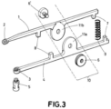
- Figure 3 shows an exploded view of a preferred embodiment.
- Said surgical device comprises a first tightening arm (1), at the distal end of which a first ring (2) is housed, which is intended for resting on the upper area of the coronoid.
- Figures 1, 2 and 3 show that the device comprises a second tightening arm (4) which incorporates a second ring (3), in this case threaded, in the distal portion thereof onto which an interchangeable head (5)with different reduction diameters can be screwed, which makes it possible to slide and guide needles or drill bits for performing bone tunnels, and it can further guide the insertion of one or more screws for osteosynthesis.
- a second tightening arm (4) which incorporates a second ring (3), in this case threaded, in the distal portion thereof onto which an interchangeable head (5)with different reduction diameters can be screwed, which makes it possible to slide and guide needles or drill bits for performing bone tunnels, and it can further guide the insertion of one or more screws for osteosynthesis.
- the head (5) is interchangeable and removable for performing tunnels of different diameters and synthesising fractures of any size or morphology with needles, screws or suture between bones by means of open surgery.
- the first ring (2) and second ring (3) each have a mutually opposite toothed profile for increasing the friction on the coronoid and the back of the proximal ulna and for preventing sliding or loss of reduction of the fracture during surgery.
- the first ring (2) has a circular morphology of greater width (diameter) than height, in the direction of the greater shaft of the coronoid, for favouring visibility and manoeuvrability, due to the narrowness of the work space available during surgery.
- Figure 2 shows a front perspective view from the perspective or point of view of a surgeon of the described preferred embodiment, wherein the surgical device is shown being used and placed on the coronoid for bone perforation and
- Figure 3 shows an exploded view of a preferred embodiment.
- the device further comprises an intermediate portion (10) which comprises respective widened sections (11a, 11b) in both arms (1, 4) with a circular configuration or, for example, a washer shape, which are integrated around a shaft or rod (6') in the centre of said circles or washers, thus enabling a controlled clamp-type movement between the arms (1, 4).
- Said rod (6') is threaded and comprises an ergonomic wheel (6), which enables the degree of sliding and the stable fixation between both arms (1, 4) to be adjusted and acts as an adjustable brake, and it can fix the relative position of the two arms (1, 4) at any point in the range of motion.
- the device comprises a spring (9), which is housed between the proximal ends of both arms via the extensions (7) provided for this purpose, which exerts a separation force on said proximal ends of the arms (1, 4), and an approaching force on the distal ends of the arms (1, 4) and the respective rings (2 and 3) thereof, such that they exert pressure on the coronoid and on the back of the ulna once they are placed in position for perforation, thus preventing movements or loss of reduction of the fracture, and enabling the perforation and osteosynthesis process to be performed intuitively, easily, and by just one surgeon.
- a spring (9) which is housed between the proximal ends of both arms via the extensions (7) provided for this purpose, which exerts a separation force on said proximal ends of the arms (1, 4), and an approaching force on the distal ends of the arms (1, 4) and the respective rings (2 and 3) thereof, such that they exert pressure on the coronoid and on the back of the ulna once they are placed in position for
- each arm of the device (1, 4) has respective extensions (7) which act by way of a stop (8) for delimiting a minimum opening between the two rings (2, 3) of the distal ends of the arms (1, 4), preventing unnecessary degrees of travel and, ultimately, friction between the same and the deterioration thereof.
Landscapes
- Health & Medical Sciences (AREA)
- Life Sciences & Earth Sciences (AREA)
- Surgery (AREA)
- Orthopedic Medicine & Surgery (AREA)
- Medical Informatics (AREA)
- General Health & Medical Sciences (AREA)
- Biomedical Technology (AREA)
- Heart & Thoracic Surgery (AREA)
- Nuclear Medicine, Radiotherapy & Molecular Imaging (AREA)
- Molecular Biology (AREA)
- Animal Behavior & Ethology (AREA)
- Engineering & Computer Science (AREA)
- Public Health (AREA)
- Veterinary Medicine (AREA)
- Dentistry (AREA)
- Oral & Maxillofacial Surgery (AREA)
- Ophthalmology & Optometry (AREA)
- Surgical Instruments (AREA)
Claims (5)
- Chirurgische Führungsvorrichtung zur Knochenperforation bei Osteosyntheseverfahren, insbesondere bei Coronoidfrakturen der Ulna, welche umfasst:- einen ersten Spannarm (1), der an einem distalen Ende einen ersten Ring (2) umfasst, der dazu bestimmt ist, auf einem gebrochenen Bereich aufzuliegen,- einen zweiten Spannarm (4), der an einem distalen Ende einen zweiten Ring (3) umfasst, der dazu bestimmt ist, auf dem dorsalen Bereich der proximalen Ulna zu ruhen, wobei der zweite Ring (3) mit einem Kopf (5) verbunden ist, wobei jeder Arm (1, 4) einen Zwischenabschnitt (10) umfasst, der seinerseits entsprechende verbreiterte Abschnitte (11a, 11b) umfasst, die miteinander mittels einer Stange (6') verbunden sind, die konzentrisch zu den verbreiterten Abschnitten (11a, 11b) ist, was eine kontrollierte klemmartige Bewegung zwischen den Armen (1, 4) ermöglicht,- eine Feder (9), die mit einem proximalen Ende jedes Arms (1, 4) mittels entsprechender Verlängerungen (7) verbunden ist, dadurch gekennzeichnet, dass die Feder (9) konfiguriert ist, um die proximalen Enden beider Arme (1, 4) auseinander zu ziehen und folglich Druck auf die distalen Enden auszuüben, was es den Ringen (2, 3) ermöglicht, Druck auf den gebrochenen Bereich auszuüben, wodurch Bewegungen verhindert werden, und dadurch, dass sie ferner umfasst:- ein ergonomisches Rad (6), das sich in die Stange (6') einfädeln lässt und so als Bremse wirkt und das Festziehen und Fixieren der Arme (2, 3) in einer gewünschten Öffnungsposition ermöglicht.
- Chirurgische Vorrichtung nach Anspruch 1, wobei der Kopf (5) durch eine Schraubverbindung mit dem zweiten Ring (3) austauschbar und abnehmbar ist.
- Chirurgische Vorrichtung nach Anspruch 1, wobei die Ringe (2, 3) jeweils ein einander gegenüberliegendes Zahnprofil aufweisen.
- Chirurgische Vorrichtung nach Anspruch 1, wobei der erste Ring (2) eine kreisförmige Konfiguration mit einem Durchmesser aufweist, der größer ist als die Höhe oder Dicke des ersten Rings (2), um die Sichtbarkeit und Manövrierbarkeit zu verbessern.
- Chirurgische Vorrichtung nach Anspruch 1, wobei der erste Arm (1) und der zweite Arm (4) zwei Anschläge (8) zur Begrenzung einer minimalen Öffnungsposition der Klemme umfassen.
Applications Claiming Priority (2)
| Application Number | Priority Date | Filing Date | Title |
|---|---|---|---|
| ES201931040A ES2828527A1 (es) | 2019-11-26 | 2019-11-26 | Dispositivo quirurgico de guia para una perforacion osea durante un proceso de osteosintesis especialmente para fracturas de coronoides |
| PCT/ES2020/070740 WO2021105541A1 (es) | 2019-11-26 | 2020-11-26 | Dispositivo quirúrgico de guía para una perforación ósea durante un proceso de osteosíntesis, especialmente para fracturas de coronoides del cúbito |
Publications (3)
| Publication Number | Publication Date |
|---|---|
| EP4066754A1 EP4066754A1 (de) | 2022-10-05 |
| EP4066754C0 EP4066754C0 (de) | 2023-09-13 |
| EP4066754B1 true EP4066754B1 (de) | 2023-09-13 |
Family
ID=74003810
Family Applications (1)
| Application Number | Title | Priority Date | Filing Date |
|---|---|---|---|
| EP20828993.4A Active EP4066754B1 (de) | 2019-11-26 | 2020-11-26 | Chirurgische führungsvorrichtung zur knochenperforation bei osteosyntheseverfahren, insbesondere bei coronoidfrakturen der ulna |
Country Status (3)
| Country | Link |
|---|---|
| EP (1) | EP4066754B1 (de) |
| ES (2) | ES2828527A1 (de) |
| WO (1) | WO2021105541A1 (de) |
Families Citing this family (1)
| Publication number | Priority date | Publication date | Assignee | Title |
|---|---|---|---|---|
| IT202100014666A1 (it) * | 2021-06-04 | 2022-12-04 | Dario Giunchi | Pinza ad uso ortopedico per la osteosintesi delle fratture ossee. |
Family Cites Families (14)
| Publication number | Priority date | Publication date | Assignee | Title |
|---|---|---|---|---|
| US2181746A (en) * | 1939-02-04 | 1939-11-28 | John R Siebrandt | Combination bone clamp and adjustable drill guide |
| US4312337A (en) * | 1980-09-08 | 1982-01-26 | Donohue Brian T | Cannula and drill guide apparatus |
| US9011507B2 (en) * | 2009-10-28 | 2015-04-21 | Orthopro Llc | Compression plate kit and methods for repairing bone discontinuities |
| US8998912B2 (en) * | 2011-09-28 | 2015-04-07 | Depuy (Ireland) | Clamping patella drill guide |
| GB2506373A (en) * | 2012-09-26 | 2014-04-02 | Tejas Kiran Yarashi | Bone and plate holding forceps |
| US9820759B1 (en) * | 2013-05-20 | 2017-11-21 | Ascension Orthopedics, Inc. | Drill guide for use in bone fixation |
| CN204158482U (zh) | 2014-09-26 | 2015-02-18 | 北京积水潭医院 | 一种用于外科肘关节镜下冠状突骨折定位导向器 |
| CN204683756U (zh) | 2015-03-26 | 2015-10-07 | 刘观燚 | 尺骨冠状突套索技术导向器 |
| CN205307069U (zh) * | 2015-12-15 | 2016-06-15 | 深圳市盐田区人民医院 | 内踝骨折复位和固定导向装置 |
| US10743924B2 (en) * | 2016-01-25 | 2020-08-18 | Stryker European Holdings I, Llc | Bone reduction and implant holding instrument |
| CN206729937U (zh) * | 2016-12-09 | 2017-12-12 | 陈炳鹏 | 一种骨折复位钳 |
| WO2018198119A1 (en) * | 2017-04-26 | 2018-11-01 | Lorean Dynamic Surgical Navigation Ltd. | Surgical drill guide tools |
| CN107157568A (zh) * | 2017-06-01 | 2017-09-15 | 上海市第五人民医院 | 一种骨折定位加压器 |
| CN209122415U (zh) * | 2018-05-03 | 2019-07-19 | 殷照阳 | 一种肘关节骨折复位钳 |
-
2019
- 2019-11-26 ES ES201931040A patent/ES2828527A1/es active Pending
-
2020
- 2020-11-26 ES ES20828993T patent/ES2962386T3/es active Active
- 2020-11-26 EP EP20828993.4A patent/EP4066754B1/de active Active
- 2020-11-26 WO PCT/ES2020/070740 patent/WO2021105541A1/es not_active Ceased
Also Published As
| Publication number | Publication date |
|---|---|
| EP4066754C0 (de) | 2023-09-13 |
| EP4066754A1 (de) | 2022-10-05 |
| ES2962386T3 (es) | 2024-03-18 |
| WO2021105541A1 (es) | 2021-06-03 |
| WO2021105541A4 (es) | 2021-07-22 |
| ES2828527A1 (es) | 2021-05-26 |
Similar Documents
| Publication | Publication Date | Title |
|---|---|---|
| US10736678B2 (en) | Compression plate kit and methods for repairing bone discontinuities | |
| US12396770B2 (en) | Devices and techniques for treating metatarsus adductus | |
| US11058467B2 (en) | Bone stabilization systems | |
| US5746743A (en) | Single-handed surgical drill depth guide with mandibular retractor | |
| US6423061B1 (en) | High tibial osteotomy method and apparatus | |
| US9687258B2 (en) | Aiming device | |
| US5601565A (en) | Osteotomy method and apparatus | |
| US7465303B2 (en) | External fixation assembly | |
| US20180256222A1 (en) | Bone stabilization systems | |
| CA2670797A1 (en) | Apparatus for repositioning portions of fractured bone and method of using same | |
| KR20050075440A (ko) | 조정가능한 본 플레이트 | |
| JP2007268278A (ja) | 可変角髄内釘 | |
| AU2007201413A1 (en) | Variable angle intramedullary nail, assembly and method | |
| US11974788B2 (en) | Adjustable angle orthopedic distractor and/or compressor | |
| Memarzadeh et al. | Intramedullary nailing of femoral shaft fractures in adults | |
| EP4066754A1 (de) | Chirurgische führungsvorrichtung zur knochenperforation bei osteosyntheseverfahren, insbesondere bei coronoidfrakturen der ulna | |
| CN108720893A (zh) | 一种微创扇形截骨器及其使用方法 | |
| CN218500756U (zh) | 一种跟距轴向撑开器 | |
| Prusick et al. | Open reduction and pinning of lateral condyle fractures | |
| RU79411U1 (ru) | Пластины для металлоостеосинтеза проксимального отдела бедренной кости (варианты), инструменты для их установки | |
| CN209404874U (zh) | 一种微创扇形截骨器 | |
| US12232790B2 (en) | Adjustable angle orthopedic distractor, compressor, and distractor-compressor | |
| US7967825B2 (en) | Coronoid process fracture fixator | |
| CN2457975Y (zh) | 一种具有交锁固定结构的股骨颈及头固定螺钉 | |
| RU2746973C1 (ru) | Устройство для фиксации стержней Шанца и Штейнмана |
Legal Events
| Date | Code | Title | Description |
|---|---|---|---|
| STAA | Information on the status of an ep patent application or granted ep patent |
Free format text: STATUS: UNKNOWN |
|
| STAA | Information on the status of an ep patent application or granted ep patent |
Free format text: STATUS: THE INTERNATIONAL PUBLICATION HAS BEEN MADE |
|
| PUAI | Public reference made under article 153(3) epc to a published international application that has entered the european phase |
Free format text: ORIGINAL CODE: 0009012 |
|
| STAA | Information on the status of an ep patent application or granted ep patent |
Free format text: STATUS: REQUEST FOR EXAMINATION WAS MADE |
|
| 17P | Request for examination filed |
Effective date: 20220506 |
|
| AK | Designated contracting states |
Kind code of ref document: A1 Designated state(s): AL AT BE BG CH CY CZ DE DK EE ES FI FR GB GR HR HU IE IS IT LI LT LU LV MC MK MT NL NO PL PT RO RS SE SI SK SM TR |
|
| DAV | Request for validation of the european patent (deleted) | ||
| DAX | Request for extension of the european patent (deleted) | ||
| GRAP | Despatch of communication of intention to grant a patent |
Free format text: ORIGINAL CODE: EPIDOSNIGR1 |
|
| STAA | Information on the status of an ep patent application or granted ep patent |
Free format text: STATUS: GRANT OF PATENT IS INTENDED |
|
| RIC1 | Information provided on ipc code assigned before grant |
Ipc: A61B 17/90 20060101ALI20230331BHEP Ipc: A61B 17/88 20060101ALI20230331BHEP Ipc: A61B 17/17 20060101AFI20230331BHEP |
|
| INTG | Intention to grant announced |
Effective date: 20230502 |
|
| RAP3 | Party data changed (applicant data changed or rights of an application transferred) |
Owner name: ADMINISTRACION GENERAL DE LA COMUNIDAD AUTONOMA DE EUSKADI |
|
| GRAS | Grant fee paid |
Free format text: ORIGINAL CODE: EPIDOSNIGR3 |
|
| GRAA | (expected) grant |
Free format text: ORIGINAL CODE: 0009210 |
|
| STAA | Information on the status of an ep patent application or granted ep patent |
Free format text: STATUS: THE PATENT HAS BEEN GRANTED |
|
| AK | Designated contracting states |
Kind code of ref document: B1 Designated state(s): AL AT BE BG CH CY CZ DE DK EE ES FI FR GB GR HR HU IE IS IT LI LT LU LV MC MK MT NL NO PL PT RO RS SE SI SK SM TR |
|
| REG | Reference to a national code |
Ref country code: CH Ref legal event code: EP |
|
| REG | Reference to a national code |
Ref country code: DE Ref legal event code: R096 Ref document number: 602020017773 Country of ref document: DE |
|
| REG | Reference to a national code |
Ref country code: IE Ref legal event code: FG4D |
|
| U01 | Request for unitary effect filed |
Effective date: 20231009 |
|
| U07 | Unitary effect registered |
Designated state(s): AT BE BG DE DK EE FI FR IT LT LU LV MT NL PT SE SI Effective date: 20231017 |
|
| U20 | Renewal fee for the european patent with unitary effect paid |
Year of fee payment: 4 Effective date: 20231129 |
|
| PG25 | Lapsed in a contracting state [announced via postgrant information from national office to epo] |
Ref country code: GR Free format text: LAPSE BECAUSE OF FAILURE TO SUBMIT A TRANSLATION OF THE DESCRIPTION OR TO PAY THE FEE WITHIN THE PRESCRIBED TIME-LIMIT Effective date: 20231214 |
|
| PG25 | Lapsed in a contracting state [announced via postgrant information from national office to epo] |
Ref country code: RS Free format text: LAPSE BECAUSE OF FAILURE TO SUBMIT A TRANSLATION OF THE DESCRIPTION OR TO PAY THE FEE WITHIN THE PRESCRIBED TIME-LIMIT Effective date: 20230913 Ref country code: NO Free format text: LAPSE BECAUSE OF FAILURE TO SUBMIT A TRANSLATION OF THE DESCRIPTION OR TO PAY THE FEE WITHIN THE PRESCRIBED TIME-LIMIT Effective date: 20231213 Ref country code: HR Free format text: LAPSE BECAUSE OF FAILURE TO SUBMIT A TRANSLATION OF THE DESCRIPTION OR TO PAY THE FEE WITHIN THE PRESCRIBED TIME-LIMIT Effective date: 20230913 Ref country code: GR Free format text: LAPSE BECAUSE OF FAILURE TO SUBMIT A TRANSLATION OF THE DESCRIPTION OR TO PAY THE FEE WITHIN THE PRESCRIBED TIME-LIMIT Effective date: 20231214 |
|
| REG | Reference to a national code |
Ref country code: ES Ref legal event code: FG2A Ref document number: 2962386 Country of ref document: ES Kind code of ref document: T3 Effective date: 20240318 |
|
| PG25 | Lapsed in a contracting state [announced via postgrant information from national office to epo] |
Ref country code: IS Free format text: LAPSE BECAUSE OF FAILURE TO SUBMIT A TRANSLATION OF THE DESCRIPTION OR TO PAY THE FEE WITHIN THE PRESCRIBED TIME-LIMIT Effective date: 20240113 |
|
| PG25 | Lapsed in a contracting state [announced via postgrant information from national office to epo] |
Ref country code: SM Free format text: LAPSE BECAUSE OF FAILURE TO SUBMIT A TRANSLATION OF THE DESCRIPTION OR TO PAY THE FEE WITHIN THE PRESCRIBED TIME-LIMIT Effective date: 20230913 Ref country code: RO Free format text: LAPSE BECAUSE OF FAILURE TO SUBMIT A TRANSLATION OF THE DESCRIPTION OR TO PAY THE FEE WITHIN THE PRESCRIBED TIME-LIMIT Effective date: 20230913 Ref country code: IS Free format text: LAPSE BECAUSE OF FAILURE TO SUBMIT A TRANSLATION OF THE DESCRIPTION OR TO PAY THE FEE WITHIN THE PRESCRIBED TIME-LIMIT Effective date: 20240113 Ref country code: CZ Free format text: LAPSE BECAUSE OF FAILURE TO SUBMIT A TRANSLATION OF THE DESCRIPTION OR TO PAY THE FEE WITHIN THE PRESCRIBED TIME-LIMIT Effective date: 20230913 Ref country code: SK Free format text: LAPSE BECAUSE OF FAILURE TO SUBMIT A TRANSLATION OF THE DESCRIPTION OR TO PAY THE FEE WITHIN THE PRESCRIBED TIME-LIMIT Effective date: 20230913 |
|
| PG25 | Lapsed in a contracting state [announced via postgrant information from national office to epo] |
Ref country code: PL Free format text: LAPSE BECAUSE OF FAILURE TO SUBMIT A TRANSLATION OF THE DESCRIPTION OR TO PAY THE FEE WITHIN THE PRESCRIBED TIME-LIMIT Effective date: 20230913 |
|
| REG | Reference to a national code |
Ref country code: DE Ref legal event code: R097 Ref document number: 602020017773 Country of ref document: DE |
|
| REG | Reference to a national code |
Ref country code: CH Ref legal event code: PL |
|
| PG25 | Lapsed in a contracting state [announced via postgrant information from national office to epo] |
Ref country code: MC Free format text: LAPSE BECAUSE OF FAILURE TO SUBMIT A TRANSLATION OF THE DESCRIPTION OR TO PAY THE FEE WITHIN THE PRESCRIBED TIME-LIMIT Effective date: 20230913 |
|
| PG25 | Lapsed in a contracting state [announced via postgrant information from national office to epo] |
Ref country code: CH Free format text: LAPSE BECAUSE OF NON-PAYMENT OF DUE FEES Effective date: 20231130 |
|
| PLBE | No opposition filed within time limit |
Free format text: ORIGINAL CODE: 0009261 |
|
| STAA | Information on the status of an ep patent application or granted ep patent |
Free format text: STATUS: NO OPPOSITION FILED WITHIN TIME LIMIT |
|
| PG25 | Lapsed in a contracting state [announced via postgrant information from national office to epo] |
Ref country code: MC Free format text: LAPSE BECAUSE OF FAILURE TO SUBMIT A TRANSLATION OF THE DESCRIPTION OR TO PAY THE FEE WITHIN THE PRESCRIBED TIME-LIMIT Effective date: 20230913 Ref country code: CH Free format text: LAPSE BECAUSE OF NON-PAYMENT OF DUE FEES Effective date: 20231130 |
|
| 26N | No opposition filed |
Effective date: 20240614 |
|
| REG | Reference to a national code |
Ref country code: IE Ref legal event code: MM4A |
|
| PG25 | Lapsed in a contracting state [announced via postgrant information from national office to epo] |
Ref country code: IE Free format text: LAPSE BECAUSE OF NON-PAYMENT OF DUE FEES Effective date: 20231126 |
|
| PG25 | Lapsed in a contracting state [announced via postgrant information from national office to epo] |
Ref country code: IE Free format text: LAPSE BECAUSE OF NON-PAYMENT OF DUE FEES Effective date: 20231126 |
|
| U21 | Renewal fee for the european patent with unitary effect paid with additional fee |
Year of fee payment: 5 Effective date: 20250410 |
|
| GBPC | Gb: european patent ceased through non-payment of renewal fee |
Effective date: 20241126 |
|
| PG25 | Lapsed in a contracting state [announced via postgrant information from national office to epo] |
Ref country code: CY Free format text: LAPSE BECAUSE OF FAILURE TO SUBMIT A TRANSLATION OF THE DESCRIPTION OR TO PAY THE FEE WITHIN THE PRESCRIBED TIME-LIMIT; INVALID AB INITIO Effective date: 20201126 |
|
| PG25 | Lapsed in a contracting state [announced via postgrant information from national office to epo] |
Ref country code: HU Free format text: LAPSE BECAUSE OF FAILURE TO SUBMIT A TRANSLATION OF THE DESCRIPTION OR TO PAY THE FEE WITHIN THE PRESCRIBED TIME-LIMIT; INVALID AB INITIO Effective date: 20201126 |
|
| PG25 | Lapsed in a contracting state [announced via postgrant information from national office to epo] |
Ref country code: GB Free format text: LAPSE BECAUSE OF NON-PAYMENT OF DUE FEES Effective date: 20241126 |
|
| U20 | Renewal fee for the european patent with unitary effect paid |
Year of fee payment: 6 Effective date: 20251023 |
|
| PG25 | Lapsed in a contracting state [announced via postgrant information from national office to epo] |
Ref country code: TR Free format text: LAPSE BECAUSE OF FAILURE TO SUBMIT A TRANSLATION OF THE DESCRIPTION OR TO PAY THE FEE WITHIN THE PRESCRIBED TIME-LIMIT Effective date: 20230913 |
|
| PGFP | Annual fee paid to national office [announced via postgrant information from national office to epo] |
Ref country code: ES Payment date: 20251201 Year of fee payment: 6 |