EP4065865B1 - Integration eines getriebestellers - Google Patents
Integration eines getriebestellers Download PDFInfo
- Publication number
- EP4065865B1 EP4065865B1 EP20806955.9A EP20806955A EP4065865B1 EP 4065865 B1 EP4065865 B1 EP 4065865B1 EP 20806955 A EP20806955 A EP 20806955A EP 4065865 B1 EP4065865 B1 EP 4065865B1
- Authority
- EP
- European Patent Office
- Prior art keywords
- transmission
- movement
- actuator
- shift
- gear
- Prior art date
- Legal status (The legal status is an assumption and is not a legal conclusion. Google has not performed a legal analysis and makes no representation as to the accuracy of the status listed.)
- Active
Links
Images
Classifications
-
- F—MECHANICAL ENGINEERING; LIGHTING; HEATING; WEAPONS; BLASTING
- F16—ENGINEERING ELEMENTS AND UNITS; GENERAL MEASURES FOR PRODUCING AND MAINTAINING EFFECTIVE FUNCTIONING OF MACHINES OR INSTALLATIONS; THERMAL INSULATION IN GENERAL
- F16H—GEARING
- F16H63/00—Control outputs from the control unit to change-speed- or reversing-gearings for conveying rotary motion or to other devices than the final output mechanism
- F16H63/02—Final output mechanisms therefor; Actuating means for the final output mechanisms
- F16H63/30—Constructional features of the final output mechanisms
- F16H63/3013—Constructional features of the final output mechanisms the final output mechanism being characterised by linkages converting movement, e.g. into opposite direction by a pivoting lever linking two shift rods
-
- F—MECHANICAL ENGINEERING; LIGHTING; HEATING; WEAPONS; BLASTING
- F16—ENGINEERING ELEMENTS AND UNITS; GENERAL MEASURES FOR PRODUCING AND MAINTAINING EFFECTIVE FUNCTIONING OF MACHINES OR INSTALLATIONS; THERMAL INSULATION IN GENERAL
- F16H—GEARING
- F16H63/00—Control outputs from the control unit to change-speed- or reversing-gearings for conveying rotary motion or to other devices than the final output mechanism
- F16H63/02—Final output mechanisms therefor; Actuating means for the final output mechanisms
- F16H63/04—Final output mechanisms therefor; Actuating means for the final output mechanisms a single final output mechanism being moved by a single final actuating mechanism
-
- F—MECHANICAL ENGINEERING; LIGHTING; HEATING; WEAPONS; BLASTING
- F16—ENGINEERING ELEMENTS AND UNITS; GENERAL MEASURES FOR PRODUCING AND MAINTAINING EFFECTIVE FUNCTIONING OF MACHINES OR INSTALLATIONS; THERMAL INSULATION IN GENERAL
- F16H—GEARING
- F16H63/00—Control outputs from the control unit to change-speed- or reversing-gearings for conveying rotary motion or to other devices than the final output mechanism
- F16H63/02—Final output mechanisms therefor; Actuating means for the final output mechanisms
- F16H63/30—Constructional features of the final output mechanisms
- F16H63/3016—Final output mechanisms varying the leverage or force ratio
-
- F—MECHANICAL ENGINEERING; LIGHTING; HEATING; WEAPONS; BLASTING
- F16—ENGINEERING ELEMENTS AND UNITS; GENERAL MEASURES FOR PRODUCING AND MAINTAINING EFFECTIVE FUNCTIONING OF MACHINES OR INSTALLATIONS; THERMAL INSULATION IN GENERAL
- F16H—GEARING
- F16H63/00—Control outputs from the control unit to change-speed- or reversing-gearings for conveying rotary motion or to other devices than the final output mechanism
- F16H63/02—Final output mechanisms therefor; Actuating means for the final output mechanisms
- F16H63/30—Constructional features of the final output mechanisms
- F16H63/3023—Constructional features of the final output mechanisms the final output mechanisms comprising elements moved by fluid pressure
-
- F—MECHANICAL ENGINEERING; LIGHTING; HEATING; WEAPONS; BLASTING
- F16—ENGINEERING ELEMENTS AND UNITS; GENERAL MEASURES FOR PRODUCING AND MAINTAINING EFFECTIVE FUNCTIONING OF MACHINES OR INSTALLATIONS; THERMAL INSULATION IN GENERAL
- F16H—GEARING
- F16H63/00—Control outputs from the control unit to change-speed- or reversing-gearings for conveying rotary motion or to other devices than the final output mechanism
- F16H63/02—Final output mechanisms therefor; Actuating means for the final output mechanisms
- F16H63/30—Constructional features of the final output mechanisms
- F16H63/304—Constructional features of the final output mechanisms the final output mechanisms comprising elements moved by electrical or magnetic force
Definitions
- the present invention relates to a transmission with a transmission actuator, a drive train and a vehicle.
- a component can be designed to be more space-saving, the space saved can either be used to install other components or a housing can be pulled tighter around certain components.
- gearbox actuator for setting a gear position, which is represented by a transmission stage ("gear"), or for setting a neutral position in the gearbox, whereby the gearbox actuator carries out an adjusting movement which is impressed directly or via intermediate elements on a switching element, in particular on a shift sleeve, whereby this is displaced so that the desired gear position is set.
- the adjusting movement of the gearbox actuator is oriented parallel to the gearbox shaft axis, which means that the gearbox actuator also extends essentially parallel to the gearbox shaft axis.
- the problem here is that there is free space between the outer contour of the transmission stages, for example between the outer diameter of the gears on the gearbox shaft, and the gearbox actuator.
- a parallel arrangement of the actuating movement and the gear shaft axis can have disadvantages in terms of installation space, particularly in the case of short gears or gears with a rising or falling housing geometry, as well as in terms of mechanical support with regard to vibrations.
- the generic document DE102016002824A1 shows an automated manual transmission, wherein the actuation axis of an actuator, which is connected to shift sleeves of the transmission, is aligned perpendicular to the actuation direction of the shift sleeves.
- US 5 794 381 A shows a selectively switchable motor drive assembly that can be operated to move a vehicle door or ramp to enable manual operation or motorized operation.
- the US 2015 / 176 687 A1 shows an electric vehicle axle with a gear ratio with a switchable superposition gear with a first and a second gear stage.
- the EN 10 2012 222 540 A1 an arrangement for switching at least two idler gears on two associated shafts for a transmission of a vehicle.
- the characteristic orientations of a respective transmission actuator proposed in the prior art run perpendicular to a transmission shaft.
- a transmission is provided with a transmission actuator for setting at least one shift position in the transmission, which has at least one transmission shaft, wherein the transmission actuator is designed to carry out an adjusting movement in an adjusting direction in order to set the shift position, wherein a characteristic orientation direction of the transmission actuator is not oriented parallel to the transmission shaft axis of the at least one transmission shaft, wherein the characteristic orientation direction is the adjusting direction.
- the transmission has two different gear ratios, which are formed by gear stages and have different outer diameters.
- the adjusting direction is arranged essentially parallel to a tangent to the outer contour of the two gear ratios, wherein the two gear ratios are arranged on the same transmission shaft.
- the characteristic orientation direction is a main extension direction of the gear actuator, in which the maximum extension of the gear actuator runs compared to the extensions of the gear actuator in the other two spatial directions.
- the gear actuator essentially has a width of 100 mm, a depth of 70 mm and a length of 200 mm
- the extension direction along which the length of the gear actuator extends is the main extension direction or the characteristic orientation direction.
- the characteristic orientation direction is the adjustment direction of the gear actuator.
- the gear actuator therefore preferably has a design that allows the gear actuator to be mounted in or on the gearbox so that its main extension direction and/or its adjustment direction are not oriented parallel to the gearbox shaft axis.
- the gear actuator can be designed for mounting using fastening means, such as screws.
- the main extension direction and the adjustment direction of the gear actuator are parallel to each other or identical to each other.
- the characteristic orientation direction of the gear actuator and the gear shaft axis of the at least one gear shaft are oriented to each other such that they intersect at an angle.
- a skewed orientation of the characteristic orientation direction of the gear actuator and the gear shaft axis can also be provided.
- the gear actuator can preferably be actuated hydraulically, pneumatically, electrically, magnetically and/or mechanically.
- the actuating movement is preferably translational.
- a piston is preferably provided which is moved by hydraulic or pneumatic pressure in order to carry out the actuating movement.
- Mechanical actuation can be achieved in particular by a combination of rack and pinion, by a worm gear or by a ball screw.
- electrical or magnetic actuation the required force is generated by electrical or magnetic fields.
- an electric motor can drive a ball screw, which mechanically causes an actuating movement.
- the characteristic orientation direction in particular the setting direction and/or the main extension direction, is arranged essentially parallel to a tangent to the outer contour of two gear ratios, with the two gear ratios being arranged on the same gear shaft.
- the gear actuator can be oriented according to the outer contour of the gear ratios, which in particular achieves the desired space saving.
- the gear ratios are formed by gear stages. The outermost dimension of the gear ratios can be seen as the outer contour. For a gear stage, this corresponds to the outer or tip diameter of the gear.
- the transmission has a transmission mechanism for transmitting an actuating movement, in particular a transmission actuator as described above, which has a first coupling point which is designed to come into contact with the gear actuator and to absorb its actuating movement, and which has a second coupling point which is designed to come into contact with a shifting element of the transmission, in particular with a shift sleeve, wherein the transmission mechanism is designed to convert the actuating movement into a switching movement which effects an adjustment of a switching position in the transmission.
- the linear actuating movement of the transmission actuator does not have to be implemented parallel to the switching movement of the shifting element. Instead, a possibility is now created to provide the transmission actuator with a different orientation in the transmission.
- the transmission mechanism can also be designed to convert an actuating movement which is oriented parallel to the transmission shaft axis into a switching movement.
- the term "coupling point” is understood to mean in particular a point or an element of the transmission mechanism via which the actuating movement can be impressed on the transmission mechanism or via which the switching movement can be transmitted.
- the coupling points therefore represent interfaces via which the transmission mechanism can come into contact with the gear actuator or with the switching element. These interfaces can be designed in different ways, as shown below by way of example.
- the transmission mechanism has a transmission element which is designed to convert the adjusting movement into the switching movement.
- the transmission element can be designed as a rod or have a rod, for example.
- the transmission element is designed to effect a translation of the actuating movement into the switching movement.
- Both an over- and a reduction ratio can be provided.
- a 1:1 translation is also conceivable, so that the actuating movement corresponds to a movement that covers the same distance as the resulting switching movement.
- the gear actuator that carries out the actuating movement is smaller or less powerful compared to an embodiment with
- a gear ratio can be designed as a gear ratio because the force that is applied from the gear actuator to the switching element via the transmission mechanism is increased at the same time.
- With a gear ratio it is advantageous that the distance covered by the actuating movement is smaller than the distance covered by the switching movement. This means that less installation space needs to be provided for the gear actuator or for its actuating movement.
- the transmission element is rotatably mounted and designed to generate a switching movement through the adjustment movement by means of rotation.
- the transmission element is preferably rotatably mounted in a pivot point that lies between the coupling points.
- the transmission ratio can thus be determined by the respective distances between the pivot point and the respective coupling points, whereby other influences, such as a contact surface pairing or length compensation, as described below, can further influence the transmission ratio.
- the pivot point is preferably provided on the transmission actuator or integrated in the transmission actuator, so that the transmission actuator and the transmission element form an integral unit which can be easily mounted directly onto the transmission, wherein the transmission element particularly preferably establishes a mechanical connection to the switching element (e.g. by engaging in a shift sleeve) during assembly.
- the transmission element can be specifically designed as a shift fork, or can have a shift fork in addition to other elements.
- the shift fork is preferably designed to be connected to the switching element in the second coupling point in order to impose the switching movement on it.
- the transmission element is designed to be translationally displaceable, in particular parallel to the transmission shaft axis, in order to convert the actuating movement into the switching movement.
- the translational displaceability can be provided as an alternative or in addition to the rotatable mounting of the transmission element. In the case of additional displaceability, In combination with the rotating bearing, a complex movement of the transmission element is also possible in order to translate the adjusting movement into a switching movement.
- the transmission mechanism preferably has a length compensation mechanism which is designed to carry out a length compensation between the coupling points when the actuating movement is applied. Since the actuating movement is not oriented parallel to the transmission shaft axis, a length compensation must be carried out between the coupling points.
- This length compensation mechanism can be designed in different ways. If the connection of the transmission actuator or the switching element in the respective coupling point is realized by means of a bearing which allows a rotary movement between the transmission actuator or switching element and the transmission mechanism, a length compensation must be carried out between the two coupling points. The same applies if the connection in the coupling points does not allow a rotary movement.
- the length compensation mechanism is preferably designed as part of the transmission element. For example, a rolling or plain bearing can be provided as a bearing.
- the length compensation mechanism preferably has an elastic preload that acts between the coupling points.
- This elastic preload can preferably be generated by a spring.
- the elastic preload preferably ensures that the length compensation mechanism is always subjected to a force, so that the transmission element always strives to expand between the coupling points.
- a transmission which has a transmission actuator as described above and a transmission mechanism as described above, wherein the transmission actuator is connected via the first coupling point to the transmission mechanism for imparting the actuating movement to the transmission mechanism.
- the transmission mechanism has a transmission element that can be rotated about a pivot point
- this pivot point is preferably provided on the gear actuator or integrated into it, as already explained above.
- connection between the gear actuator and the transmission mechanism is designed to be rotationally fixed in the first coupling point.
- this connection can also be designed in one piece.
- an element of the transmission mechanism preferably the element that transmits the switching movement to the switching element, and the element of the gear actuator that carries out the actuating movement, are designed as one component.
- connection between the gear actuator and the transmission mechanism in the first coupling point can also be designed to be rotatable or have a contact surface pairing.
- a rotatable design can be achieved in particular by a sliding or rolling bearing, via which the transmission mechanism, preferably its transmission element, and the element of the gear actuator that carries out the actuating movement are connected.
- the connection between the transmission mechanism, preferably the transmission element, and the element of the gear actuator that carries out the actuating movement is made by contact between the two elements. These are designed in such a way that they only abut one another so that the actuating movement can be impressed on the transmission mechanism. For this purpose, contact surfaces are formed on both elements.
- the contact surface pairing can be designed in such a way that both contact surfaces roll and/or slide against one another in their contact and/or carry out a relative movement to one another in order to represent the rotary movement or length compensation.
- a transmission is provided as described above, which has a switching element, in particular a switching sleeve.
- the switching element is designed to carry out a switching movement in order to set a switching position in the transmission.
- the switching element is connected to the second Coupling point connected to the transmission mechanism for imparting the switching movement to the switching element.
- the gear actuator is arranged in the transmission such that a characteristic orientation direction of the gear actuator, as described above, is not arranged parallel to a transmission shaft axis.
- the characteristic orientation direction in particular the adjustment direction and/or the main extension direction, is arranged substantially parallel to a tangent to the outer contour of two gear ratio stages, wherein the two gear ratio stages are preferably arranged on the same transmission shaft.
- connection between the switching element and the transmission mechanism in the second coupling point is designed to be rotationally fixed.
- this connection can also be designed in one piece.
- an element of the transmission mechanism preferably the element to which the actuating movement of the gear actuator is applied, and the switching element are designed as one component.
- connection between the switching element and the transmission mechanism can be designed to be rotatable at the second coupling point or can have a contact surface pairing.
- a rotatable design can be achieved in particular by a sliding or rolling bearing, via which the transmission mechanism, preferably its transmission element, and the switching element are connected.
- the connection between the transmission mechanism, preferably the transmission element, and the switching element is made by contact between the two elements. These are designed in such a way that they only abut one another so that the switching movement can be impressed on the switching element. For this purpose, contact surfaces are formed on both elements.
- the contact surface pairing can be designed in such a way that both contact surfaces roll and/or slide against one another in their contact and/or carry out a relative movement to one another in order to represent the rotary movement or length compensation.
- Transmission mechanism preferably its transmission element, and the switching element are connected.
- a contact surface pairing the connection between the transmission mechanism, preferably the transmission element, and the switching element exists through contact between the two elements. These are designed in such a way that they merely abut one another so that the switching movement can be impressed on the switching element.
- contact surfaces are formed on both elements.
- the contact surface pairing can be designed in such a way that both contact surfaces roll and/or slide against one another in their contact and/or carry out a relative movement to one another in order to represent the rotary movement or the length compensation.
- a drive train for a vehicle which has a transmission as described above.
- a vehicle which has a transmission as described above or a drive train as described above.
- the vehicle is electrically or hybrid-powered and/or designed as a commercial vehicle.
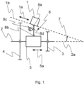
- the gear actuator 1 is designed to carry out an adjusting movement 1a, which is shown in the drawing by the double arrow as a translatory movement.
- the adjusting movement 1a can thus be carried out parallel to an adjusting direction 1b, which is indicated in the drawing by a dashed line.
- the adjusting direction 1b is inclined relative to the gear shaft axis 2a by an inclination angle 7, so that the adjusting direction 1b and the gear shaft axis 2a are not oriented parallel to one another.
- the adjusting direction 1b corresponds to the characteristic orientation direction of the gear actuator 1, as described above.
- the transmission shaft 2 whose transmission shaft axis 2a is oriented horizontally from left to right, has a first gear 3 and a second gear 4, which are provided for rotation on the transmission shaft 2. Both gears 3, 4 have different radii and thus form different gear ratios. Furthermore, a switching element 5 in the form of a switching sleeve is provided on the transmission shaft 2 between the gears 3, 4. This switching element 5 is designed to be displaceable in a switching movement 5a, which is oriented here as a translational movement parallel to the transmission shaft axis 2a. The switching element 5 is provided on the transmission shaft 2 so as to be fixed against rotation about the transmission shaft axis 2a.
- the arrangement of the transmission shaft 2, gears 3, 4 and switching element 5 shown here corresponds to an arrangement known from transmission construction.
- the switching element 5 is moved to the right in accordance with a switching movement 5a.
- the switching element 5 comes into contact with the first gear 3 and forms a rotationally fixed connection around the transmission shaft axis 2a, so that the first gear 3 is now rotationally fixedly connected to the transmission shaft 2 via the switching element 5.
- Setting the switching position, via the gear ratio represented by the second gear 4 is carried out analogously by a switching movement 5a of the switching element 5 to the left.
- the adjustment direction 1b is oriented according to the outer contour of the gear ratios of the gear shaft 2. In concrete terms, this means that the adjustment direction 1b is oriented parallel to a tangent to the gears 3, 4. General Such orientation can also be carried out parallel to a three-dimensional envelope of the gear ratio stages.
- a transmission mechanism 8 is provided for transmitting the actuating movement 1a to the switching element 5, so that the switching element 5 can carry out the switching movement 5a.
- the transmission mechanism 8 has a first coupling point 8a, via which the gear actuator 1 is coupled to the transmission mechanism 8.
- the transmission mechanism 8 has a further second coupling point 8b, via which the switching element 5 is coupled to the transmission mechanism 8.
- the transmission mechanism 8 further comprises a transmission element 8c which is provided so as to be rotatable about a pivot point 8d and which is designed to translate the actuating movement 1a, which is impressed on the first coupling point 8a, into the switching movement 5a.
- connection between the gear actuator 1 and the switching element 5 can be designed differently at the coupling points 8a, 8b.
- At least one connection in one of the two coupling points 8a, 8b can be designed to be articulated, so that the transmission element 8c can rotate about the first coupling point 8a relative to the gear actuator 1 and/or about the second coupling point 8b relative to the switching element 5.
- a bearing in particular a plain or roller bearing, is provided in the corresponding coupling point 8a, 8b.
- the transmission mechanism 8 has a length compensation mechanism (not shown), which is designed to carry out the length compensation between the two coupling points 8a, 8b.
- the length compensation mechanism can be implemented, for example, by a transmission element 8c, which is designed to be variable in its extension between the coupling points 8a, 8b. When the transmission element 8c rotates, it is ensured that the transmission element 8c can follow the changing distance between the coupling points 8a, 8b.
- the length compensation mechanism can also have an elastic pre-tensioning force, which can be applied by a spring, for example.
- the elastic pre-tensioning force is oriented so that it acts between the coupling points 8a, 8b and is oriented so that it always acts in the direction of extension of the transmission element 8c. In this way, a change in the length of the rod can be supported by the elastic pre-tensioning force, so that the length compensation can take place reliably.
- a length compensation mechanism can have a transmission element 8c in the form of a rod, which is connected with its ends in the coupling points 8a, 8b by means of sliding or rolling bearings to the gear actuator 1 or to the switching element 5.
- the rod thus extends between the coupling points 8a, 8b.
- a spring is provided, the elastic preload force of which acts between the coupling points 8a, 8b and causes the rod to always maximize its extension between the coupling points 8a, 8b.
- a contact surface pairing can be provided in the second coupling point 8b, with one contact surface being formed on the switching element 5 and the other contact surface on the transmission element 8c.
- the respective contact surfaces in the contact surface pairings are designed to roll and/or slide against one another.
- at least one contact surface can be curved. If the transmission element 8c rotates about the pivot point 8d, the contact surfaces in the corresponding contact surface pairings roll and/or slide. Due to the rolling and/or sliding process, the contact point between the contact surfaces within the contact surface pairing migrates. Length compensation therefore does not necessarily have to be provided here, since this is achieved by the moving contact point.
- connection of the transmission element 8c in at least one of the coupling points 8a, 8b with the gear actuator 1 and/or with the switching element 5 can also be designed in one piece.
- an element of the gear actuator 1 that carries out the actuating movement 1a is designed in one piece with the transmission element 8c in the first coupling point 8a.
- the switching element 5 can also be designed in one piece with the transmission element 8c in the second coupling point 8b.
- the gear actuator 1 can be actuated in particular hydraulically, pneumatically, electrically, magnetically and/or mechanically.
- the functionality of the arrangement shown is as follows: First of all, the arrangement shown is arranged as shown.
- the switching element 5 is located between the gears 3, 4.
- the arrangement is therefore in the neutral position.
- the gear actuator 1 carries out an adjusting movement 1a in the adjusting direction 1b in the drawing to the top left.
- the first coupling point 8a is moved along the adjusting direction 1b to the top left, whereby the transmission element 8c is rotated by the Pivot point 8d is rotated anti-clockwise.
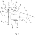
- Fig. 2 shows a second embodiment of the invention.
- an arrangement of a gear actuator 1, a transmission mechanism 8 and a gear shaft 2 is shown in a sectional view.
- the embodiment shown here differs from that of Fig.1 by a different design of the transmission mechanism 8.
- the gear actuator 1 and the gear shaft 2 are identical to those of Fig.1 identical. For an explanation of these, please refer to the comments on Fig.1 referred to.
- the adjustment direction 1b of the gear actuator 1 corresponds to the characteristic orientation direction of the gear actuator 1.
- the transmission mechanism 8 here has a transmission element 8c, which is connected to the transmission actuator 1 at a first coupling point 8a and to the switching element 5 at a second coupling point 8b.
- the transmission element 8c is not rotatably mounted here. Instead, it is designed to be displaceable parallel to the gear shaft axis 2a. This can be achieved, for example, by a guide (not shown) that guides the transmission element 8c parallel to the gear shaft axis 2a.
- the guide can also be designed to guide the transmission element 8c in such a way that it is prevented from rotating, the axis of rotation of which is oriented perpendicular to the plane of the drawing.
- connection in the coupling points 8a, 8b between the transmission element 8c and the transmission actuator 1 or the switching element 5 can be designed in the same way as in the embodiment of Fig.1 .
- a length compensation mechanism (not shown) must also be provided between the coupling points 8a, 8b in order to carry out a length compensation. This can also be Fig.1 described.
- the functionality of the arrangement shown is as follows: First of all, the arrangement shown is arranged as shown.
- the switching element 5 is located between the gears 3, 4.
- the arrangement is therefore in the neutral position.
- the gear actuator 1 carries out an adjusting movement 1a in the adjusting direction 1b to the bottom right in the drawing. This moves the first coupling point 8a along the adjusting direction 1b to the bottom right, whereby the transmission element 8c is moved to the right.
- This also moves the second coupling point 8b and thus the switching element 5 in a switching movement 5a to the right parallel to the gear shaft axis 2a.
- Both coupling points 8a, 8b move towards each other here, since the length compensation mechanism allows the transmission element 8c to be shortened.
- the switching movement 5a to the right takes place until the switching element 5 hits the first gear 3, whereby, as described above, the desired switching position is set.
- the setting of another switching position namely that represented by the second gear 4 or the neutral position, is carried out analogously by a corresponding adjustment movement 1a of the gear actuator 1 to the top left or back to the position shown.
- the adjustment direction 1b of the gear actuator 1 is not oriented parallel to a tangent to the gears 3, 4. Rather, the adjustment direction 1b can be oriented in any way. Instead, a main extension direction of the gear actuator 1 can be oriented parallel to the tangent to the gears 3, 4 as a characteristic orientation direction. This ensures that the gear actuator 1 with its greatest extension direction to the outer contour of the gear ratios, which are embodied by the gears 3, 4.
Landscapes
- Engineering & Computer Science (AREA)
- General Engineering & Computer Science (AREA)
- Mechanical Engineering (AREA)
- Physics & Mathematics (AREA)
- Fluid Mechanics (AREA)
- Gear-Shifting Mechanisms (AREA)
Description
- Die vorliegende Erfindung bezieht sich auf ein Getriebe mit einem Getriebesteller, einen Antriebsstrang sowie ein Fahrzeug.
- In der Fahrzeugentwicklung spielt die optimale Ausnutzung von Bauraum eine entscheidende Rolle. Kann beispielsweise eine Komponente platzsparender ausgeführt werden, so steht der dadurch eingesparte Bauraum entweder für den Einbau anderer Komponenten zur Verfügung oder es kann beispielsweise ein Gehäuse enger um gewisse Komponenten gezogen werden.
- Im Getriebebau ist es üblich, einen Getriebesteller zur Einstellung einer Schaltstellung, die durch eine Übersetzungsstufe ("Gang") verkörpert ist, oder zur Einstellung einer Neutralstellung in dem Getriebe vorzusehen, wobei der Getriebesteller hierzu eine Stellbewegung ausführt, die direkt oder über Zwischenelemente auf ein Schaltelement, insbesondere auf eine Schaltmuffe, aufgeprägt wird, wodurch diese verschoben wird, so dass die gewünschte Schaltstellung eingestellt wird. Die Stellbewegung des Getriebestellers ist dabei parallel zu der Getriebewellenachse orientiert, was zur Folge hat, dass auch der Getriebesteller sich im Wesentlichen parallel zu der Getriebewellenachse erstreckt. Hier besteht das Problem, dass zwischen der Außenkontur der Übersetzungsstufen, also beispielsweise zwischen dem Außendurchmesser der Zahnräder auf der Getriebewelle, und dem Getriebesteller freier Bauraum vorliegt.
- Eine parallele Anordnung der Stellbewegung sowie der Getriebewellenachse kann insbesondere bei kurzen Getrieben bzw. bei Getrieben mit einer ansteigenden oder abfallenden Gehäusegeometrie Nachteile in Bezug auf Bauraum haben sowie in Bezug auf die mechanische Abstützung hinsichtlich Schwingungen.
- Aus dem Stand der Technik sind Mechanismen zur Einstellung von Schaltstellungen in einem Getriebe bekannt. Das gattungsgemässe Dokument
DE102016002824A1 zeigt ein automatisiertes Schaltgetriebe, wobei die Betätigungsachse eines Stellgliedes eines Aktuators, das mit Schaltmuffen des Getriebes verbunden ist, senkrecht zur Betätigungsrichtung der Schaltmuffen ausgerichtet ist.US 5 794 381 A zeigt eine selektiv einschaltbare MotorAntriebs-Baugruppe, die zum Bewegen einer Fahrzeugtür oder -rampe betätigt werden kann, um einen manuellen Betrieb oder einen motorisierten Betrieb zu ermöglichen. DieUS 2015 / 176 687 A1 zeigt eine elektrische Fahrzeugachse mit einer Übersetzung mit einem schaltbaren Überlagerungsgetriebe mit einer ersten und einer zweiten Gangstufe. Schließlich zeigt dieDE 10 2012 222 540 A1 eine Anordnung zum Schalten von zumindest zwei Losrädern an zwei zugeordneten Wellen für ein Getriebe eines Fahrzeugs. Die jeweils im Stand der Technik vorgeschlagenen charakteristischen Orientierungen eines jeweiligen Getriebestellers verlaufen senkrecht gegenüber einer Getriebewelle. - Es ist somit Aufgabe der vorliegenden Erfindung, Möglichkeiten aufzuzeigen, um diesen Bauraum einzusparen.
- Diese Aufgabe wird durch die Gegenstände des unabhängigen Anspruchs gelöst. Vorteilhafte Weiterbildungen sind Gegenstand der Unteransprüche.
- Erfindungsgemäß ist ein Getriebe mit einem Getriebesteller zum Einstellen zumindest einer Schaltstellung in dem Getriebe, das zumindest eine Getriebewelle aufweist, vorgesehen, wobei der Getriebesteller dazu ausgebildet ist, zum Einstellen der Schaltstellung eine Stellbewegung in einer Stellrichtung auszuführen, wobei eine charakteristische Orientierungsrichtung des Getriebestellers gegenüber der Getriebewellenachse der zumindest einen Getriebewelle nicht parallel orientiert ist wobei die charakteristische Orientierungsrichtung die Stellrichtung ist. Das Getriebe weist zwei unterschiedliche Übersetzungsstufen auf, die durch Zahnradstufen ausgebildet sind und unterschiedliche Außendurchmesser aufweisen. Die Stellrichtung ist im Wesentlichen parallel zu einer Tangente an die Außenkontur der zwei Übersetzungsstufen angeordnet, wobei die zwei Übersetzungsstufen auf derselben Getriebewelle angeordnet sind.
- Vorzugsweise ist die charakteristische Orientierungsrichtung eine Haupterstreckungsrichtung des Getriebestellers, in der die maximale Erstreckung des Getriebestellers gegenüber den Erstreckungen des Getriebestellers in den anderen beiden Raumrichtungen verläuft. Weist der Getriebesteller beispielsweise im Wesentlichen eine Breite von 100mm, eine Tiefe von 70mm und eine Länge von 200mm auf, so ist die Erstreckungsrichtung, entlang der sich die Länge des Getriebestellers erstreckt, die Haupterstreckungsrichtung bzw. die charakteristische Orientierungsrichtung. Die charakteristische Orientierungsrichtung ist die Stellrichtung des Getriebestellers.
- Der Getriebesteller weist demnach bevorzugt eine Ausbildung auf, die erlaubt, den Getriebesteller in oder an dem Getriebe zu montieren, so dass dessen Haupterstreckungsrichtung und/oder dessen Stellrichtung nicht parallel zu der Getriebewellenachse orientiert sind/ist. Insbesondere kann der Getriebesteller zur Montage mittels Befestigungsmitteln, wie z.B. Schrauben, ausgebildet sein.
- Vorzugsweise sind die Haupterstreckungsrichtung und die Stellrichtung des Getriebestellers parallel zueinander bzw. miteinander identisch.
- Vorzugsweise sind die charakteristische Orientierungsrichtung des Getriebestellers und die Getriebewellenachse der zumindest einen Getriebewelle so zueinander orientiert, dass sie sich unter einem Winkel schneiden. Alternativ kann auch eine windschiefe Orientierung der charakteristischen Orientierungsrichtung des Getriebestellers und der Getriebewellenachse vorgesehen sein.
- Vorzugsweise ist der Getriebesteller hydraulisch, pneumatisch, elektrisch, magnetisch und/oder mechanisch betätigbar. Die Stellbewegung ist dabei bevorzugt translatorisch ausgebildet. Bei hydraulischer oder pneumatischer Betätigung ist bevorzugt ein Kolben vorgesehen, der durch einen hydraulischen oder pneumatischen Druck bewegt wird, um die Stellbewegung auszuführen. Eine mechanische Betätigung kann insbesondere durch eine Kombination aus Zahnstange und Ritzel, durch ein Schneckengetriebe oder durch eine Kugelumlaufspindel realisiert sein. Bei elektrischer oder magnetischer Betätigung wird die benötigte Kraft durch elektrische oder magnetische Felder erzeugt. Schließlich können auch verschiedene Prinzipien kombiniert sein. So kann beispielsweise ein Elektromotor eine Kugelumlaufspindel antreiben, wodurch mechanisch eine Stellbewegung hervorgerufen wird.
- Die charakteristische Orientierungsrichtung, insbesondere die Stellrichtung und/oder die Haupterstreckungsrichtung, ist im Wesentlichen parallel zu einer Tangente an die Außenkontur von zwei Übersetzungsstufen angeordnet, wobei die zwei Übersetzungsstufen auf derselben Getriebewelle angeordnet sind. So wird erreicht, dass der Getriebesteller entsprechend der Außenkontur der Übersetzungsstufen orientiert werden kann, wodurch insbesondere die gewünschte Bauraumeinsparung erreicht wird. Die Übersetzungsstufen sind durch Zahnradstufen ausgebildet. Als Außenkontur kann die äußerste Abmessung der Übersetzungsstufen gesehen werden. Bei einer Zahnradstufe entspricht dies dem Außen- bzw. Kopfkreisdurchmesser des Zahnrades.
- Vorzugsweise weist das Getriebe einen Übertragungsmechanismus zum Übertragen einer Stellbewegung, insbesondere eines Getriebestellers wie oben beschrieben, auf, der einen ersten Koppelpunkt
aufweist, der dazu ausgebildet ist, mit dem Getriebesteller, in Kontakt zu treten und dessen Stellbewegung aufzunehmen, und der
einen zweiten Koppelpunkt aufweist, der dazu ausgebildet ist, mit einem Schaltelement des Getriebes, insbesondere mit einer Schaltmuffe, in Kontakt zu treten, wobei der Übertragungsmechanismus dazu ausgebildet ist, die Stellbewegung in eine Schaltbewegung umzusetzen, die eine Einstellung einer Schaltstellung in dem Getriebe bewirkt. So kann vorteilhafterweise erreicht werden, dass die geradlinige Stellbewegung des Getriebestellers eben nicht parallel zu der Schaltbewegung des Schaltelements umgesetzt werden muss. Stattdessen ist nun eine Möglichkeit geschaffen, den Getriebesteller unter einer anderen Orientierung in dem Getriebe vorzusehen. Der Übertragungsmechanismus kann jedoch auch geeignet ausgebildet sein, um eine Stellbewegung, die parallel zu der Getriebewellenachse orientiert ist, in eine Schaltbewegung umzusetzen. - Unter dem Begriff "Koppelpunkt" wird in dieser Anmeldung insbesondere eine Stelle bzw. ein Element des Übertragungsmechanismus' verstanden worüber die Stellbewegung auf den Übertragungsmechanismus aufgeprägt werden kann, bzw. worüber die Schaltbewegung abgegeben werden kann. Die Koppelpunkte stellen daher Schnittstellen dar, über die der Übertragungsmechanismus mit dem Getriebesteller bzw. mit dem Schaltelement in Kontakt treten kann. Diese Schnittstellen können unterschiedlich ausgebildet sein, wie weiter unten beispielhaft gezeigt wird.
- Vorzugsweise weist der Übertragungsmechanismus ein Übertragungselement auf, das dazu ausgebildet ist, die Stellbewegung in die Schaltbewegung umzusetzen. Das Übertragungselement kann beispielsweise als Stab ausgebildet sein oder einen Stab aufweisen.
- Vorzugsweise ist das Übertragungselement dazu ausgebildet, eine Übersetzung der Stellbewegung in die Schaltbewegung zu bewirken. Dabei können sowohl eine Überals auch eine Untersetzung vorgesehen sein. Auch eine 1:1-Übersetzung ist denkbar, so dass die Stellbewegung einer Bewegung entspricht, die eine gleichlange Strecke zurücklegt, wie die daraus resultierende Schaltbewegung. Bei einer Untersetzung, d.h. wenn die Stellbewegung eine längere Strecke zurücklegt als die daraus resultierende Schaltbewegung, ist vorteilhaft, dass der Getriebesteller, der die Stellbewegung ausführt, kleiner bzw. leistungsschwächer im Vergleich zu einer Ausführungsform mit Übersetzung ausgelegt werden kann, da gleichzeitig die Kraft, die über den Übertragungsmechanismus von dem Getriebesteller auf das Schaltelement aufgebracht wird, vergrößert wird. Bei einer Übersetzung ist wiederum vorteilhaft, dass die Strecke, die die Stellbewegung zurücklegt, kleiner als die Strecke der Schaltbewegung ist. Dadurch muss weniger Bauraum für den Getriebesteller bzw. für dessen Stellbewegung vorgesehen werden.
- Vorzugsweise ist das Übertragungselement drehbar gelagert und dazu ausgebildet, durch die Stellbewegung mittels Drehung eine Schaltbewegung zu erzeugen. Das Übertragungselement ist hierbei bevorzugt in einem Drehpunkt, der zwischen den Koppelpunkten liegt, drehbar gelagert. Die Übersetzung kann somit durch die jeweiligen Abstände zwischen Drehpunkt und den jeweiligen Koppelpunkten bestimmt werden, wobei weitere Einflüsse, wie beispielsweise eine Kontaktflächenpaarung oder ein Längenausgleich, wie weiter unten beschrieben, die Übersetzung weiter beeinflussen können.
- Der Drehpunkt ist vorzugsweise am Getriebesteller vorgesehen oder im Getriebesteller integriert, sodass der Getriebesteller und das Übertragungselement eine integrale Einheit bilden, die entsprechend einfach direkt auf das Getriebe montiert werden kann, wobei besonders bevorzugt das Übertragungselement bei der Montage direkt eine mechanische Verbindung zu dem Schaltelement (z.B. durch Eingriff in eine Schaltmuffe) herstellt.
- Das Übertragungselement kann speziell als Schaltgabel ausgebildet sein, oder neben weiteren Elementen eine Schaltgabel aufweisen. Die Schaltgabel ist vorzugsweise dazu ausgebildet, mit dem Schaltelement in dem zweiten Koppelpunkt verbunden zu werden, um auf dieses die Schaltbewegung aufzuprägen.
- Vorzugsweise ist das Übertragungselement translatorisch verschiebbar, insbesondere parallel verschiebbar zur Getriebewellenachse, ausgebildet, um die Umsetzung der Stellbewegung in die Schaltbewegung zu bewirken. Die translatorische Verschiebbarkeit kann alternativ oder zusätzlich zu der drehbaren Lagerung des Übertragungselementes vorgesehen sein. Bei einer zusätzlichen Verschiebbarkeit ist in Kombination mit der drehbaren Lagerung auch eine komplexe Bewegung des Übertragungselementes möglich, um die Stellbewegung in eine Schaltbewegung zu übersetzen.
- Vorzugsweise weist der Übertragungsmechanismus einen Längenausgleichsmechanismus auf, der dazu ausgebildet ist, einen Längenausgleich zwischen den Koppelpunkten bei Aufbringen der Stellbewegung durchzuführen. Da die Stellbewegung nicht parallel zu der Getriebewellenachse orientiert ist muss zwischen den Koppelpunkten ein Längenausgleich durchgeführt werden. Dieser Längenausgleichsmechanismus kann unterschiedlich ausgebildet sein. Ist die Verbindung des Getriebestellers bzw. des Schaltelements in dem jeweiligen Koppelpunkt mittels eines Lagers, das eine Drehbewegung zwischen Getriebesteller bzw. Schaltelement und Übertragungsmechanismus zulässt, realisiert, so muss zwischen beiden Koppelpunkten ein Längenausgleich durchgeführt werden. Gleiches gilt auch, wenn die Verbindung in den Koppelpunkten keine Drehbewegung zulässt. Der Längenausgleichsmechanismus ist bevorzugt als Teil des Übertragungselementes ausgebildet. Als Lager kann beispielsweise ein Wälz- oder Gleitlager vorgesehen sein.
- Vorzugsweise weist der Längenausgleichsmechanismus eine elastische Vorspannung auf, die zwischen den Koppelpunkten wirkt. Diese elastische Vorspannung kann vorzugsweise durch eine Feder erzeugt werden. Durch die elastische Vorspannung wird bevorzugt bewirkt, dass der Längenausgleichsmechanismus stets mit einer Kraft beaufschlagt wird, so dass das Übertragungselement stets bestrebt ist, sich zwischen den Koppelpunkten auszudehnen.
- Vorzugsweise ist ein Getriebe vorgesehen, das einen Getriebesteller, wie oben beschrieben, und einen Übertragungsmechanismus, wie oben beschrieben, aufweist, wobei der Getriebesteller über den ersten Koppelpunkt mit dem Übertragungsmechanismus zur Aufprägung der Stellbewegung auf den Übertragungsmechanismus verbunden ist.
- Weist der Übertragungsmechanismus ein um einen Drehpunkt drehbares Übertragungselement auf, so ist dieser Drehpunkt vorzugsweise an dem Getriebesteller vorgesehen oder in diesen integriert, wie bereits oben ausgeführt.
- Vorzugsweise ist die Verbindung zwischen dem Getriebesteller und dem Übertragungsmechanismus in dem ersten Koppelpunkt drehfest ausgebildet. Alternativ oder zusätzlich kann diese Verbindung auch einstückig ausgebildet sein. D.h. in dem ersten Koppelpunkt sind ein Element des Übertragungsmechanismus', vorzugsweise das Element, das die Schaltbewegung auf das Schaltelement überträgt, und das Element des Getriebestellers, das die Stellbewegung ausführt, als ein Bauteil ausgebildet.
- Alternativ kann die Verbindung zwischen dem Getriebesteller und dem Übertragungsmechanismus in dem ersten Koppelpunkt auch drehbar ausgebildet sein oder eine Kontaktflächenpaarung aufweisen. Eine drehbare Ausbildung kann insbesondere durch ein Gleit- oder Wälzlager erreicht werden, über das der Übertragungsmechanismus, vorzugsweise dessen Übertragungselement, und das Element des Getriebestellers, das die Stellbewegung durchführt, verbunden sind. Bei einer Kontaktflächenpaarung besteht die Verbindung zwischen dem Übertragungsmechanismus, vorzugsweise dem Übertragungselement, und dem Element des Getriebestellers, das die Stellbewegung durchführt, durch einen Kontakt beider Elemente. Diese sind so konzipiert, dass sie lediglich aneinander anstoßen, so dass die Stellbewegung auf den Übertragungsmechanismus aufgeprägt werden kann. Dazu sind Kontaktflächen an beiden Elementen ausgebildet. Insbesondere bei drehbar vorgesehenem Übertragungselement oder zur Realisierung eines Längenausgleichs, kann die Kontaktflächenpaarung so ausgebildet sein, dass beide Kontaktflächen in ihrem Kontakt aneinander abwälzen und/oder abgleiten und/oder eine Relativbewegung zueinander ausführen, um die Drehbewegung bzw. den Längenausgleich darzustellen.
- Vorzugsweise ist ein Getriebe vorgesehen, wie oben beschrieben, das ein Schaltelement, insbesondere eine Schaltmuffe, aufweist. Dabei ist das Schaltelement dazu ausgebildet, eine Schaltbewegung durchzuführen, um in dem Getriebe eine Schaltstellung einzustellen. Dabei ist das Schaltelement über den zweiten Koppelpunkt mit dem Übertragungsmechanismus zur Aufprägung der Schaltbewegung auf das Schaltelement verbunden.
- Vorzugsweise ist der Getriebesteller so in dem Getriebe angeordnet, dass eine charakteristische Orientierungsrichtung des Getriebestellers, wie oben beschrieben, nicht parallel zu einer Getriebewellenachse angeordnet ist. Besonders bevorzugt ist die charakteristische Orientierungsrichtung, insbesondere die Stellrichtung und/oder die Haupterstreckungsrichtung, im Wesentlichen parallel zu einer Tangente an die Außenkontur von zwei Übersetzungsstufen angeordnet, wobei die zwei Übersetzungsstufen vorzugsweise auf derselben Getriebewelle angeordnet sind.
- Vorzugsweise ist die Verbindung zwischen dem Schaltelement und dem Übertragungsmechanismus in dem zweiten Koppelpunkt drehfest ausgebildet. Alternativ oder zusätzlich kann diese Verbindung auch einstückig ausgebildet sein. D.h. in dem zweiten Koppelpunkt sind ein Element des Übertragungsmechanismus', vorzugsweise das Element, dem die Stellbewegung des Getriebestellers aufgeprägt wird, und das Schaltelement, als ein Bauteil ausgebildet.
- Alternativ kann die Verbindung zwischen dem Schaltelement und dem Übertragungsmechanismus in dem zweiten Koppelpunkt drehbar ausgebildet sein oder eine Kontaktflächenpaarung aufweisen. Eine drehbare Ausbildung kann insbesondere durch ein Gleit- oder Wälzlager erreicht werden, über das der Übertragungsmechanismus, vorzugsweise dessen Übertragungselement, und das Schaltelement verbunden sind. Bei einer Kontaktflächenpaarung besteht die Verbindung zwischen dem Übertragungsmechanismus, vorzugsweise dem Übertragungselement, und dem Schaltelement durch einen Kontakt beider Elemente. Diese sind so konzipiert, dass sie lediglich aneinander anstoßen, so dass die Schaltbewegung auf das Schaltelement aufgeprägt werden kann. Dazu sind Kontaktflächen an beiden Elementen ausgebildet. Insbesondere bei drehbar vorgesehenem Übertragungselement oder zur Realisierung eines Längenausgleichs, kann die Kontaktflächenpaarung so ausgebildet sein, dass beide Kontaktflächen in ihrem Kontakt aneinander abwälzen und/oder abgleiten und/oder eine Relativbewegung zueinander ausführen, um die Drehbewegung bzw. den Längenausgleich darzustellen.
- Übertragungsmechanismus, vorzugsweise dessen Übertragungselement, und das Schaltelement verbunden sind. Bei einer Kontaktflächenpaarung besteht die Verbindung zwischen dem Übertragungsmechanismus, vorzugsweise dem Übertragungselement, und dem Schaltelement durch einen Kontakt beider Elemente. Diese sind so konzipiert, dass sie lediglich aneinander anstoßen, so dass die Schaltbewegung auf das Schaltelement aufgeprägt werden kann. Dazu sind Kontaktflächen an beiden Elementen ausgebildet. Insbesondere bei drehbar vorgesehenem Übertragungselement oder zur Realisierung eines Längenausgleichs, kann die Kontaktflächenpaarung so ausgebildet sein, dass beide Kontaktflächen in ihrem Kontakt aneinander abwälzen und/oder abgleiten und/oder eine Relativbewegung zueinander ausführen, um die Drehbewegung bzw. den Längenausgleich darzustellen. Erfindungsgemäß ist ein Antriebsstrang für ein Fahrzeug vorgesehen, der ein Getriebe wie oben beschrieben aufweist.
- Erfindungsgemäß ist ein Fahrzeug vorgesehen, das ein Getriebe, wie oben beschrieben, oder einen Antriebsstrang, wie oben beschrieben, aufweist. Vorzugsweise ist das Fahrzeug elektrisch oder hybridisch angetrieben und/oder als Nutzfahrzeug ausgebildet.
- Die Erfindung, welche durch die nachfolgenden Ansprüche definiert wird, ist nicht auf die oben beschriebenen Ausführungsformen beschränkt Vielmehr können weitere Ausführungsformen erhalten werden, indem einzelne Merkmale miteinander kombiniert, durch andere ersetzt oder weggelassen werden. Nachfolgend wird die Erfindung daher anhand bevorzugter Ausführungsbeispiele unter Zuhilfenahme der beigefügten Zeichnungen näher beschrieben.
- Der Getriebesteller 1 ist dazu ausgebildet, eine Stellbewegung 1a durchzuführen, die in der Zeichnung durch den Doppelpfeil als translatorische Bewegung dargestellt ist. Die Stellbewegung 1a kann somit parallel zu einer Stellrichtung 1b ausgeführt werden, die in der Zeichnung durch eine gestrichelte Linie angedeutet ist. Die Stellrichtung 1b ist gegenüber der Getriebewellenachse 2a um einen Neigungswinkel 7 geneigt, so dass die Stellrichtung 1b und die Getriebewellenachse 2a nicht parallel zueinander orientiert sind. In der gezeigten Ausführungsform entspricht die Stellrichtung 1b der charakteristischen Orientierungsrichtung des Getriebestellers 1, wie oben beschrieben.
- Die Getriebewelle 2, deren Getriebewellenachse 2a waagrecht von links nach rechts orientiert ist, weist ein erstes Zahnrad 3 und ein zweites Zahnrad 4 auf, die drehbar auf der Getriebewelle 2 vorgesehen sind. Beide Zahnräder 3, 4 weisen unterschiedliche Radien auf und bilden somit unterschiedliche Übersetzungsstufen. Weiter ist zwischen den Zahnrädern 3, 4 ein Schaltelement 5 in Form einer Schaltmuffe auf der Getriebewelle 2 vorgesehen. Dieses Schaltelement 5 ist in einer Schaltbewegung 5a verschiebbar ausgebildet, die hier als translatorische Bewegung parallel zur Getriebewellenachse 2a orientiert ist. Das Schaltelement 5 ist drehfest um die Getriebewellenachse 2a auf der Getriebewelle 2 vorgesehen.
- Die hier gezeigte Anordnung von Getriebewelle 2, Zahnrädern 3, 4 und Schaltelement 5 entspricht einer Anordnung, wie sie aus dem Getriebebau bekannt ist. Zum Einstellen einer Schaltstellung, beispielsweise über die Übersetzungsstufe, die durch das erste Zahnrad 3 verkörpert ist, wird das Schaltelement 5 entsprechend einer Schaltbewegung 5a nach rechts bewegt. Hier tritt das Schaltelement 5 mit dem ersten Zahnrad 3 in Kontakt und bildet um die Getriebewellenachse 2a eine drehfeste Verbindung aus, so dass nun das erste Zahnrad 3 über das Schaltelement 5 drehfest mit der Getriebewelle 2 verbunden ist. Das Einstellen der Schaltstellung, der über die Übersetzungsstufe, die durch das zweite Zahnrad 4 verkörpert ist, erfolgt analog durch eine Schaltbewegung 5a des Schaltelements 5 nach links.
- In der gezeigten Anordnung ist die Stellrichtung 1b entsprechend der Außenkontur der Übersetzungsstufen der Getriebewelle 2 orientiert. Konkret bedeutet dies, dass die Stellrichtung 1b parallel zu einer Tangente an die Zahnräder 3, 4 orientiert ist. Allgemein kann eine solche Orientierung auch parallel zu einer dreidimensionalen Hüllkurve an die Übersetzungsstufen erfolgen.
- Weiter ist zur Übertragung der Stellbewegung 1a an das Schaltelement 5 ein Übertragungsmechanismus 8 vorgesehen, so dass das Schaltelement 5 die Schaltbewegung 5a ausführen kann. Der Übertragungsmechanismus 8 weist einen ersten Koppelpunkt 8a auf, über den der Getriebesteller 1 mit dem Übertragungsmechanismus 8 gekoppelt ist. Der Übertragungsmechanismus 8 weist einen weiteren zweiten Koppelpunkt 8b auf, über den das Schaltelement 5 mit dem Übertragungsmechanismus 8 gekoppelt ist.
- Der Übertragungsmechanismus 8 weist ferner ein Übertragungselement 8c auf, das um einen Drehpunkt 8d drehbar vorgesehen ist und das dazu ausgebildet ist, die Stellbewegung 1a, die auf den ersten Koppelpunkt 8a aufgeprägt wird, in die Schaltbewegung 5a zu übersetzen.
- Die Verbindung von Getriebesteller 1 und Schaltelement 5 kann in den Koppelpunkten 8a, 8b unterschiedlich ausgeführt sein.
- In einer Ausführungsform kann zumindest eine Verbindung in einem der beiden Koppelpunkte 8a, 8b gelenkig ausgebildet sein, so dass sich das Übertragungselement 8c um den ersten Koppelpunkt 8a relativ zu dem Getriebesteller 1 und/oder um den zweiten Koppelpunkt 8b relativ zu dem Schaltelement 5 drehen kann. Dabei kann beispielsweise vorgesehen sein, dass in dem entsprechenden Koppelpunkt 8a, 8b ein Lager, insbesondere ein Gleit- oder Wälzlager, vorgesehen ist. Bei einer solchen Verbindung muss der Teil des Übertragungselementes 8c, der mit dem entsprechenden Koppelpunkt 8a, 8b verbunden ist, dem Lager stets folgen können. Daher muss aufgrund der nicht parallelen Orientierung der Getriebewellenachse 2a zu der Bewegungsrichtung 1b unter dem Winkel 7, bei einer Drehbewegung des Übertragungsmechanismus' 8 um den Drehpunkt 8d ein Längenausgleich durchgeführt werden, um den ersten Koppelunkt 8a parallel zu der Stellrichtung 1b und den zweiten Koppelpunkt 8b parallel zu der Getriebewellenachse 2a nachzuführen. Dazu weist der Übertragungsmechanismus 8 einen Längenausgleichsmechanismus (nicht gezeigt) auf, der dazu ausgebildet ist, den Längenausgleich zwischen beiden Koppelpunkten 8a, 8b durchzuführen.
- Der Längenausgleichsmechanismus kann beispielsweise durch ein Übertragungselement 8c realisiert sein, das zwischen den Koppelpunkten 8a, 8b in seiner Erstreckung veränderbar ausgebildet ist. Bei einer Drehbewegung des Übertragungselementes 8c ist dabei gewährleistet, dass das Übertragungselement 8c dem sich ändernden Abstand der Koppelpunkte 8a, 8b folgen kann.
- Der Längenausgleichsmechanismus kann darüber hinaus eine elastische Vorspannkraft aufweisen, die beispielsweise durch eine Feder aufgebracht werden kann. Die elastische Vorspannkraft ist dabei so orientiert, dass sie zwischen den Koppelpunkten 8a, 8b wirkt und so orientiert ist, dass sie stets in Erstreckungsrichtung des Übertragungselementes 8c wirkt. Auf diese Weise kann eine Längenänderung des Stabes durch die elastische Vorspannkraft unterstützt werden, so dass der Längenausgleich zuverlässig erfolgen kann.
- In einer konkreten Ausführungsform kann ein Längenausgleichsmechanismus ein Übertragungselement 8c in Form eines Stabes aufweisen, der mit seinen Enden in den Koppelpunkten 8a, 8b mittels Gleit- oder Wälzlagern drehbar an den Getriebesteller 1 bzw. an das Schaltelement 5 angebunden ist. Der Stab erstreckt sich somit zwischen den Koppelpunkten 8a, 8b. Darüber hinaus ist eine Feder vorgesehen, deren elastische Vorspannkraft zwischen den Koppelpunkten 8a, 8b wirkt und den Stab dazu veranlasst, stets seine Erstreckung zwischen den Koppelpunkten 8a, 8b zu maximieren.
- Die Verbindung des Übertragungselementes 8c in zumindest einem der Koppelpunkte 8a, 8b kann jedoch auch als abwälzende und/oder abgleitende Ankopplung ausgebildet sein. Dazu ist in zumindest einem der Koppelpunkte 8a, 8b eine Kontaktflächenpaarung (nicht gezeigt) ausgebildet, über die das Übertragungselement 8c mit dem Getriebesteller 1 und/oder mit dem Schaltelement 5 in Kontakt steht. Die Stellbewegung 1b des Getriebestellers 1 kann nun über die Kontaktflächenpaarung in dem ersten Koppelpunkt 8a auf das Übertragungselement 8c übertragen werden, wobei eine Kontaktfläche auf dem Getriebesteller 1 und die andere Kontaktfläche auf dem Übertragungselement 8c ausgebildet ist. Genauso kann auch eine Drehbewegung des Übertragungselementes 8c auf das Schaltelement 5 übertragen werden. Auch hier kann in dem zweiten Koppelpunkt 8b eine Kontaktflächenpaarung vorgesehen sein, wobei eine Kontaktfläche auf dem Schaltelement 5 und die andere Kontaktfläche auf dem Übertragungselement 8c ausgebildet ist. Die jeweiligen Kontaktflächen in den Kontaktflächenpaarungen sind dazu ausgebildet, um aneinander abzuwälzen und/oder abzugleiten. Dazu kann zumindest eine Kontaktfläche gekrümmt ausgebildet sein. Dreht sich das Übertragungselement 8c um den Drehpunkt 8d, so erfolgt ein Abwälzen und/oder Abgleiten der Kontaktflächen in den entsprechenden Kontaktflächenpaarungen. Dabei wandert aufgrund des Abwälz-und/oder Abgleitvorgangs der Kontaktpunkt zwischen den Kontaktflächen innerhalb der Kontaktflächenpaarung. Ein Längenausgleich muss daher hier nicht zwingend vorgesehen sein, da dies durch den wandernden Kontaktpunkt realisiert ist.
- Die Verbindung des Übertragungselementes 8c in zumindest einem der Koppelpunkte 8a, 8b mit dem Getriebesteller 1 und/oder mit dem Schaltelement 5 kann auch einstückig ausgebildet sein. D.h. ein Element des Getriebestellers 1 das die Stellbewegung 1a ausführt, ist in dem ersten Koppelpunkt 8a einstückig mit dem Übertragungselement 8c ausgebildet. Alternativ oder zusätzlich kann auch das Schaltelement 5 in dem zweiten Koppelpunkt 8b einstückig mit dem Übertragungselement 8c ausgebildet sein.
- Der Getriebesteller 1 ist je nach Ausführungsform insbesondere hydraulisch, pneumatisch, elektrisch, magnetisch und/oder mechanisch betätigbar.
- Die Funktionsweise der gezeigten Anordnung stellt sich wie folgt dar:
Zunächst ist die gezeigte Anordnung wie dargestellt angeordnet. Das Schaltelement 5 befindet sich zwischen den Zahnrädern 3, 4. Somit befindet sich die Anordnung in der Neutralstellung. Zum Einstellen einer Schaltstellung, die durch das erste Zahnrad 3 verkörpert ist, führt der Getriebesteller 1 eine Stellbewegung 1a in Stellrichtung 1b in der Zeichnung nach links oben aus. Dadurch wird der erste Koppelpunkt 8a entlang der Stellrichtung 1b nach links oben bewegt wodurch das Übertragungselement 8c um den Drehpunkt 8d gegen den Uhrzeigersinn gedreht wird. Dadurch wird weiter der zweite Koppelpunkt 8b und somit das Schaltelement 5 in einer Schaltbewegung 5a nach rechts parallel zu der Getriebewellenachse 2a bewegt. Dies erfolgt so weit, bis das Schaltelement 5 an das erste Zahnrad 3 stößt, wodurch, wie oben beschrieben, die gewünschte Schaltstellung eingestellt wird. Das Einstellen einer anderen Schaltstellung, nämlich der, die durch das zweite Zahnrad 4 verkörpert ist oder der Neutralstellung, erfolgt analog durch eine entsprechende Stellbewegung 1a des Getriebestellers 1 nach rechts unten bzw. zurück in die inFig. 1 gezeigte Stellung. -
Fig. 2 zeigt eine zweite Ausführungsform der Erfindung. Auch hier ist eine Anordnung eines Getriebestellers 1, eines Übertragungsmechanismus' 8 sowie einer Getriebewelle 2 in einer Schnittdarstellung gezeigt. Die hier gezeigte Ausführungsform unterscheidet sich von der ausFig. 1 durch eine andere Ausbildung des Übertragungsmechanismus' 8. Der Getriebesteller 1 sowie die Getriebewelle 2 sind mit denen ausFig. 1 identisch. Daher wird zu deren Erläuterung auf die Ausführungen zuFig. 1 verwiesen. - Auch hier entspricht die Stellrichtung 1b des Getriebestellers 1 der charakteristischen Orientierungsrichtung des Getriebestellers 1.
- Der Übertragungsmechanismus 8 weist hier ein Übertragungselement 8c auf, das in einem ersten Koppelpunkt 8a mit dem Getriebesteller 1 und in einem zweiten Koppelpunkt 8b mit dem Schaltelement 5 verbunden ist. Im Gegensatz zu der Ausführungsform, die in
Fig. 1 gezeigt ist, ist das Übertragungselement 8c hier nicht drehbar gelagert. Stattdessen ist es parallel verschiebbar zu der Getriebewellenachse 2a vorgesehen. Dies kann beispielsweise durch eine Führung (nicht gezeigt) realisiert sein, die das Übertragungselement 8c parallel zu der Getriebewellenachse 2a führt. Die Führung kann weiterhin dazu ausgebildet sein, das Übertragungselement 8c so zu führen, dass es an einer Drehung, deren Drehachse senkrecht zur Zeichenebene orientiert ist, gehindert wird. - Die Verbindung in den Koppelpunkten 8a, 8b zwischen dem Übertragungselement 8c und dem Getriebesteller 1 bzw. dem Schaltelement 5 kann hier ebenso ausgebildet sein, wie bei der Ausführungsform aus
Fig. 1 . Somit können drehbare, drehfeste, einstückige Ausbildungen und/oder Kontaktflächenpaarungen vorgesehen sein, wie sie oben zuFig. 1 beschrieben wurden. - Bei der Durchführung einer Stellbewegung durch den Getriebesteller 1 muss auch hier ein Längenausgleichsmechanismus (nicht gezeigt) zwischen den Koppelpunkten 8a, 8b vorgesehen sein, um einen Längenausgleich durchzuführen. Auch dieser kann wie zu
Fig. 1 beschrieben ausgebildet sein. - Die Funktionsweise der gezeigten Anordnung stellt sich wie folgt dar:
Zunächst ist die gezeigte Anordnung wie dargestellt angeordnet. Das Schaltelement 5 befindet sich zwischen den Zahnrädern 3, 4. Somit befindet sich die Anordnung in der Neutralstellung. Zum Einstellen einer Schaltstellung, die durch das erste Zahnrad 3 verkörpert ist, führt der Getriebesteller 1 eine Stellbewegung 1a in Stellrichtung 1b in der Zeichnung nach rechts unten aus. Dadurch wird der erste Koppelpunkt 8a entlang der Stellrichtung 1b nach rechts unten bewegt wodurch das Übertragungselement 8c nach rechts verschoben wird. Dadurch wird weiter der zweite Koppelpunkt 8b und somit das Schaltelement 5 in einer Schaltbewegung 5a nach rechts parallel zu der Getriebewellenachse 2a bewegt. Beide Koppelpunkte 8a, 8b bewegen sich hierbei aufeinander zu, da der Längenausgleichsmechanismus eine Verkürzung des Übertragungselement 8c zulässt. Die Schaltbewegung 5a nach rechts erfolgt so weit, bis das Schaltelement 5 an das erste Zahnrad 3 stößt, wodurch, wie oben beschrieben, die gewünschte Schaltstellung eingestellt wird. Das Einstellen einer anderen Schaltstellung, nämlich der, die durch das zweite Zahnrad 4 verkörpert ist oder der Neutralstellung, erfolgt analog durch eine entsprechende Stellbewegung 1a des Getriebestellers 1 nach links oben bzw. zurück in die gezeigte Stellung. - Neben den hier gezeigten Ausführungsformen sind weitere Ausführungsformen denkbar, bei denen die Stellrichtung 1b des Getriebestellers 1 nicht parallel zu einer Tangente an die Zahnräder 3, 4 orientiert ist. Vielmehr kann die Stellrichtung 1b beliebig orientiert sein. Stattdessen kann eine Haupterstreckungsrichtung des Getriebestellers 1 als charakteristische Orientierungsrichtung parallel zu der Tangente an die Zahnräder 3, 4 orientiert sein. Somit ist sichergestellt, dass sich der Getriebesteller 1 mit seiner größten Erstreckungsrichtung an die Außenkontur der Übersetzungsstufen, die durch die Zahnräder 3, 4 verkörpert sind, anpasst.
-
- 1
- Getriebesteller
- 1a
- Stellbewegung
- 1b
- Stellrichtung
- 2
- Getriebewelle
- 2a
- Getriebewellenachse
- 3
- erstes Zahnrad
- 4
- zweites Zahnrad
- 5
- Schaltelement
- 5a
- Schaltbewegung
- 7
- Neigungswinkel
- 8
- Übertragungsmechanismus
- 8a
- erster Koppelpunkt
- 8b
- zweiter Koppelpunkt
- 8c
- Übertragungselement
- 8d
- Drehpunkt
Claims (17)
- Getriebe mit einem Getriebesteller (1) zum Einstellen zumindest einer Schaltstellung in dem Getriebe, das zumindest eine Getriebewelle (2) aufweist, wobeidie Schaltstellung durch eine Übersetzungsstufe verkörpert ist, wobeider Getriebesteller (1) zum Einstellen der mindestens einen Schaltstellung dazu ausgebildet ist, eine Stellbewegung (1a) in einer Stellrichtung (1b) auszuführen, wobeieine charakteristische Orientierungsrichtung des Getriebestellers (1) gegenüber der Getriebewellenachse (2a) der zumindest einen Getriebewelle (2) nicht parallel orientiert ist, wobeidie charakteristische Orientierungsrichtung die Stellrichtung (1b) ist, wobeidas Getriebe zwei unterschiedliche Übersetzungsstufen aufweist, die durch Zahnradstufen ausgebildet sind und unterschiedliche Außendurchmesser aufweisen,dadurch gekennzeichnet, dassdie Stellrichtung (1b) im Wesentlichen parallel zu einer Tangente an die Außenkontur der zwei Übersetzungsstufen angeordnet ist, wobei die zwei Übersetzungsstufen auf derselben Getriebewelle (2) angeordnet sind.
- Getriebe nach Anspruch 1, wobei
der Getriebesteller (1) hydraulisch, pneumatisch, elektrisch, magnetisch und/oder mechanisch betätigbar ist. - Getriebe nach Anspruch 1 oder 2, aufweisend:- einen Übertragungsmechanismus (8) zum Übertragen der Stellbewegung (1a), des Getriebestellers (1), wobei der Übertragungsmechanismus (8) aufweist:- einen ersten Koppelpunkt (8a), der dazu ausgebildet ist, mit dem Getriebesteller (1), in Kontakt zu treten und dessen Stellbewegung (1a) aufzunehmen, und- einen zweiten Koppelpunkt (8b), der dazu ausgebildet ist, mit einem Schaltelement (5) des Getriebes, insbesondere mit einer Schaltmuffe, in Kontakt zu treten, wobeider Übertragungsmechanismus (8) dazu ausgebildet ist, die Stellbewegung (1a) in eine Schaltbewegung (5a) umzusetzen, die eine Einstellung einer Schaltstellung in dem Getriebe bewirkt.
- Getriebe nach Anspruch 3, aufweisend
ein Übertragungselement (8c), das dazu ausgebildet ist, die Stellbewegung (1a) in die Schaltbewegung (5a) umzusetzen. - Getriebe nach Anspruch 4, wobei
das Übertragungselement (8c) dazu ausgebildet ist, eine Übersetzung der Stellbewegung (1a) in die Schaltbewegung (5a) zu bewirken. - Getriebe nach Anspruch 4 oder 5, wobeidas Übertragungselement (8c) drehbar gelagert ist und dazu ausgebildet ist, bei Aufprägen der Stellbewegung (1a) mittels Drehung um einen Drehpunkt (8d) eine Schaltbewegung (5a) zu erzeugen, wobei vorzugsweiseder Drehpunkt (8d) des Übertragungsmechanismus (8) an oder in dem Getriebesteller (1) ausgebildet ist.
- Getriebe nach einem der Ansprüche 4 oder 5, wobei
das Übertragungselement (8c) translatorisch verschiebbar ausgebildet ist, um die Umsetzung der Stellbewegung (1a) in die Schaltbewegung (5a) zu bewirken. - Getriebe nach einem der Ansprüche 3 bis 7, aufweisend
einen Längenausgleichsmechanismus, der dazu ausgebildet ist, einen Längenausgleich zwischen den Koppelpunkten (8a, 8b) bei Aufbringen der Stellbewegung (1a) durchzuführen. - Getriebe nach Anspruch 8, wobei
der Längenausgleichsmechanismus eine elastische Vorspannung aufweist, die zwischen den Koppelpunkten (8a, 8b) wirkt. - Getriebe nach einem der Ansprüche 3 bis 9, wobei
der Getriebesteller (1) über den ersten Koppelpunkt (8a) mit dem Übertragungsmechanismus (8) zur Aufprägung der Stellbewegung (1a) auf den Übertragungsmechanismus (8) verbunden ist. - Getriebe nach einem der Ansprüche 3 bis 10, wobei
die Verbindung zwischen dem Getriebesteller (1) und dem Übertragungsmechanismus (8) in dem ersten Koppelpunkt (8a) drehfest und/oder einstückig ausgebildet ist. - Getriebe nach einem der Ansprüche 3 bis 10, wobei
die Verbindung zwischen dem Getriebesteller (1) und dem Übertragungsmechanismus (8) in dem ersten Koppelpunkt (8a) drehbar ausgebildet ist oder eine Kontaktflächenpaarung aufweist. - Getriebe nach einem der Ansprüche 3 bis 12 aufweisendein Schaltelement (5), insbesondere eine Schaltmuffe, das dazu ausgebildet ist, eine Schaltbewegung (5a) durchzuführen, um in dem Getriebe eine Schaltstellung einzustellen, wobeidas Schaltelement (5) über den zweiten Koppelpunkt (8b) mit dem Übertragungsmechanismus (8) zur Aufprägung der Schaltbewegung (5a) auf das Schaltelement (5) verbunden ist, wobeidas Getriebe vorzugsweise für ein elektrisch oder hybridisch angetriebenes Fahrzeug und/oder für ein Nutzfahrzeug ausgebildet ist.
- Getriebe nach Anspruch 13, wobei
die Verbindung zwischen dem Schaltelement (5) und dem Übertragungsmechanismus (8) in dem zweiten Koppelpunkt (8b) drehfest und/oder einstückig ausgebildet ist. - Getriebe nach Anspruch 13, wobei
die Verbindung zwischen dem Schaltelement (5) und dem Übertragungsmechanismus (8) in dem zweiten Koppelpunkt (8b) drehbar ausgebildet ist oder eine Kontaktflächenpaarung aufweist. - Antriebsstrang für ein Fahrzeug, aufweisend ein Getriebe nach einem der Ansprüche 1 bis 15, wobei
der Antriebsstrang für ein elektrisch oder hybridisch angetriebenes Fahrzeug und/oder für ein Nutzfahrzeug ausgebildet ist. - Fahrzeug aufweisend ein Getriebe nach einem der Ansprüche 1 bis 15 oder einen Antriebsstrang nach Anspruch 16, wobei
das Fahrzeug elektrisch oder hybridisch angetrieben ist und/oder ein Nutzfahrzeug ist.
Applications Claiming Priority (2)
| Application Number | Priority Date | Filing Date | Title |
|---|---|---|---|
| DE102019131935.8A DE102019131935B4 (de) | 2019-11-26 | 2019-11-26 | Integration eines Getriebestellers |
| PCT/EP2020/081686 WO2021104859A2 (de) | 2019-11-26 | 2020-11-11 | Integration eines getriebestellers |
Publications (2)
| Publication Number | Publication Date |
|---|---|
| EP4065865A2 EP4065865A2 (de) | 2022-10-05 |
| EP4065865B1 true EP4065865B1 (de) | 2024-09-25 |
Family
ID=73401486
Family Applications (1)
| Application Number | Title | Priority Date | Filing Date |
|---|---|---|---|
| EP20806955.9A Active EP4065865B1 (de) | 2019-11-26 | 2020-11-11 | Integration eines getriebestellers |
Country Status (5)
| Country | Link |
|---|---|
| US (1) | US20230003298A1 (de) |
| EP (1) | EP4065865B1 (de) |
| CN (1) | CN114729694B (de) |
| DE (1) | DE102019131935B4 (de) |
| WO (1) | WO2021104859A2 (de) |
Citations (1)
| Publication number | Priority date | Publication date | Assignee | Title |
|---|---|---|---|---|
| US2616535A (en) * | 1944-06-07 | 1952-11-04 | Glenn T Randol | Automotive variable-drive power transmission |
Family Cites Families (21)
| Publication number | Priority date | Publication date | Assignee | Title |
|---|---|---|---|---|
| US1445160A (en) * | 1921-05-06 | 1923-02-13 | Alden E Osborn | Transmission mechanism |
| US2529741A (en) * | 1948-08-16 | 1950-11-14 | Glyn P Roberts | Control mechanism for epicyclic gearboxes |
| US2807340A (en) * | 1953-03-20 | 1957-09-24 | Butterworth Archibald James | Change-speed gears for automobiles |
| US3387501A (en) * | 1965-09-10 | 1968-06-11 | Clark Equipment Co | Shift linkage transmission |
| KR900007211Y1 (ko) * | 1987-08-26 | 1990-08-11 | 박춘렬 | 차량용 변속기 |
| US5794381A (en) * | 1995-12-22 | 1998-08-18 | Ricon Corporation | Selectively engageable motor drive assembly |
| SE506066C2 (sv) * | 1996-02-28 | 1997-11-03 | Volvo Ab | Växlingsmekanism |
| EP2142826B1 (de) * | 2007-04-24 | 2015-10-28 | Fallbrook Intellectual Property Company LLC | Elektrische zugvorrichtungen |
| DE102009054942A1 (de) * | 2009-12-18 | 2011-06-22 | ZF Friedrichshafen AG, 88046 | Schalteinrichtung für ein Zahnräderwechselgetriebe |
| JP5521056B2 (ja) * | 2010-02-12 | 2014-06-11 | マグナ パワートレイン アーゲー ウント コ カーゲー | 連結装置 |
| JP5772145B2 (ja) * | 2011-03-29 | 2015-09-02 | いすゞ自動車株式会社 | 車両の自動変速装置 |
| DE102012212268B4 (de) * | 2012-07-13 | 2021-02-18 | Schaeffler Technologies AG & Co. KG | Antriebssystem für eine Elektrische Achse mit Zwei-Gang-Getriebe |
| DE102012222540B4 (de) * | 2012-12-07 | 2022-02-17 | Schaeffler Technologies AG & Co. KG | Anordnung zum Schalten von zumindest zwei Losrädern an zwei zugeordneten Wellen für ein Getriebe eines Fahrzeugs |
| DE102013216742A1 (de) * | 2013-08-23 | 2015-02-26 | Schaeffler Technologies Gmbh & Co. Kg | Schaltungsanordnung für eine Planetengetriebestufe |
| DE102014003239A1 (de) * | 2014-03-10 | 2015-09-10 | GM Global Technology Operations LLC (n. d. Ges. d. Staates Delaware) | Schaltgetriebe |
| DE102014224366B4 (de) * | 2014-11-28 | 2024-11-21 | Schaeffler Technologies AG & Co. KG | Betätigungsanordnung und Verfahren zur Betätigung einer Betätigungsvorrichtung |
| DE102016002824B4 (de) * | 2016-03-05 | 2024-01-04 | Zf Cv Systems Hannover Gmbh | Automatisiertes Schaltgetriebe |
| DE102016006751A1 (de) * | 2016-06-06 | 2017-12-07 | Knorr-Bremse Systeme für Nutzfahrzeuge GmbH | Betätigungseinheit für ein Schaltgetriebe eines schaltbaren Antriebsstranges |
| KR101866076B1 (ko) * | 2016-10-21 | 2018-06-11 | 현대자동차주식회사 | 변속기의 시프트레일 이송장치 |
| US11261964B2 (en) * | 2018-05-17 | 2022-03-01 | Black & Decker Inc. | Compliant shifting mechanism and multi-speed power tool having same |
| DE102019110044A1 (de) * | 2019-04-16 | 2020-10-22 | Schaeffler Technologies AG & Co. KG | Schalteinrichtung für ein hybrides Antriebssystem eines Kraftfahrzeuges; Antriebssystem sowie Kraftfahrzeug |
-
2019
- 2019-11-26 DE DE102019131935.8A patent/DE102019131935B4/de active Active
-
2020
- 2020-11-11 WO PCT/EP2020/081686 patent/WO2021104859A2/de not_active Ceased
- 2020-11-11 EP EP20806955.9A patent/EP4065865B1/de active Active
- 2020-11-11 CN CN202080082226.4A patent/CN114729694B/zh active Active
- 2020-11-11 US US17/779,853 patent/US20230003298A1/en not_active Abandoned
Patent Citations (1)
| Publication number | Priority date | Publication date | Assignee | Title |
|---|---|---|---|---|
| US2616535A (en) * | 1944-06-07 | 1952-11-04 | Glenn T Randol | Automotive variable-drive power transmission |
Also Published As
| Publication number | Publication date |
|---|---|
| EP4065865A2 (de) | 2022-10-05 |
| WO2021104859A2 (de) | 2021-06-03 |
| DE102019131935A1 (de) | 2021-05-27 |
| CN114729694A (zh) | 2022-07-08 |
| WO2021104859A3 (de) | 2021-07-22 |
| DE102019131935B4 (de) | 2025-12-31 |
| CN114729694B (zh) | 2023-12-19 |
| US20230003298A1 (en) | 2023-01-05 |
Similar Documents
| Publication | Publication Date | Title |
|---|---|---|
| DE19839850B4 (de) | Schaltvorrichtung für Kraftfahrzeug-Wechselgetriebe | |
| EP2232107B1 (de) | Schaltvorrichtung für mehrstufenschaltgetriebe von kraftfahrzeugen | |
| DE102023115292A1 (de) | Aktor zur Bereitstellung eines Drehmoments mit einem Linearantrieb | |
| EP2038161A2 (de) | Lenkeinrichtung und betriebsverfahren dafür | |
| EP2251567A1 (de) | Schmiermittelzuführung für eine Linearbewegungsvorrichtung | |
| DE102008000346A1 (de) | Vorrichtung zur Umwandlung einer Rotation in eine Translation | |
| DE102005060933B3 (de) | Wählhebel, insbesondere für ein Kraftfahrzeug | |
| EP3368799B1 (de) | Schaltvorrichtung und antriebseinheit für ein kraftfahrzeug | |
| EP4065865B1 (de) | Integration eines getriebestellers | |
| EP1531290B1 (de) | Schalteinrichtung | |
| WO2000037819A1 (de) | Getriebeähnlich ausgebildete vorrichtung zur betätigung der bremsbacken | |
| EP4065866B1 (de) | Aktuatormodul | |
| DE102018114971A1 (de) | Elektromechanischer Bremsenaktuator für eine Bremse | |
| EP1291560A2 (de) | Hilfskraftunterstützte Getriebeschaltvorrichtung | |
| DE102017221827B4 (de) | Betätigungsvorrichtung für ein Schaltelement und Getriebe | |
| EP2396572B1 (de) | Einrichtung zum erzeugen einer schaltkraft oder wählkraft in einem handschaltgetriebe | |
| DE102016226015B4 (de) | Verstellbare Radlagerung eines Kraftfahrzeugs | |
| DE102007038264A1 (de) | Aktiver Stabilisator zur Wankstabilisierung | |
| DE102021213247A1 (de) | Getriebevorrichtung für ein Kraftfahrzeug | |
| DE102022201484B4 (de) | Getriebevorrichtung für ein Kraftfahrzeug | |
| DE102014206713A1 (de) | Übertragungseinrichtung von Wähl- und Schaltbewegungen und damit versehene Schalteinrichtung | |
| DE102024128567B4 (de) | Lenksystem für ein Fahrzeug | |
| DE19823730B4 (de) | Verteilergetriebe insbesondere für eine Schiebedach-Anordnung eines Fahrzeuges | |
| DE102007055862A1 (de) | Verdrehsicherung mit Toleranzausgleich | |
| DE69212709T2 (de) | Hinterradlenkung |
Legal Events
| Date | Code | Title | Description |
|---|---|---|---|
| STAA | Information on the status of an ep patent application or granted ep patent |
Free format text: STATUS: UNKNOWN |
|
| STAA | Information on the status of an ep patent application or granted ep patent |
Free format text: STATUS: THE INTERNATIONAL PUBLICATION HAS BEEN MADE |
|
| PUAI | Public reference made under article 153(3) epc to a published international application that has entered the european phase |
Free format text: ORIGINAL CODE: 0009012 |
|
| STAA | Information on the status of an ep patent application or granted ep patent |
Free format text: STATUS: REQUEST FOR EXAMINATION WAS MADE |
|
| 17P | Request for examination filed |
Effective date: 20220627 |
|
| AK | Designated contracting states |
Kind code of ref document: A2 Designated state(s): AL AT BE BG CH CY CZ DE DK EE ES FI FR GB GR HR HU IE IS IT LI LT LU LV MC MK MT NL NO PL PT RO RS SE SI SK SM TR |
|
| DAV | Request for validation of the european patent (deleted) | ||
| DAX | Request for extension of the european patent (deleted) | ||
| STAA | Information on the status of an ep patent application or granted ep patent |
Free format text: STATUS: EXAMINATION IS IN PROGRESS |
|
| 17Q | First examination report despatched |
Effective date: 20230901 |
|
| RAP3 | Party data changed (applicant data changed or rights of an application transferred) |
Owner name: KNORR-BREMSE SYSTEME FUER NUTZFAHRZEUGE GMBH |
|
| GRAP | Despatch of communication of intention to grant a patent |
Free format text: ORIGINAL CODE: EPIDOSNIGR1 |
|
| STAA | Information on the status of an ep patent application or granted ep patent |
Free format text: STATUS: GRANT OF PATENT IS INTENDED |
|
| INTG | Intention to grant announced |
Effective date: 20240610 |
|
| GRAS | Grant fee paid |
Free format text: ORIGINAL CODE: EPIDOSNIGR3 |
|
| GRAA | (expected) grant |
Free format text: ORIGINAL CODE: 0009210 |
|
| STAA | Information on the status of an ep patent application or granted ep patent |
Free format text: STATUS: THE PATENT HAS BEEN GRANTED |
|
| AK | Designated contracting states |
Kind code of ref document: B1 Designated state(s): AL AT BE BG CH CY CZ DE DK EE ES FI FR GB GR HR HU IE IS IT LI LT LU LV MC MK MT NL NO PL PT RO RS SE SI SK SM TR |
|
| P01 | Opt-out of the competence of the unified patent court (upc) registered |
Free format text: CASE NUMBER: APP_48216/2024 Effective date: 20240821 |
|
| REG | Reference to a national code |
Ref country code: GB Ref legal event code: FG4D Free format text: NOT ENGLISH |
|
| REG | Reference to a national code |
Ref country code: CH Ref legal event code: EP |
|
| REG | Reference to a national code |
Ref country code: DE Ref legal event code: R096 Ref document number: 502020009341 Country of ref document: DE |
|
| REG | Reference to a national code |
Ref country code: IE Ref legal event code: FG4D Free format text: LANGUAGE OF EP DOCUMENT: GERMAN |
|
| REG | Reference to a national code |
Ref country code: SE Ref legal event code: TRGR |
|
| REG | Reference to a national code |
Ref country code: LT Ref legal event code: MG9D |
|
| PG25 | Lapsed in a contracting state [announced via postgrant information from national office to epo] |
Ref country code: NO Free format text: LAPSE BECAUSE OF FAILURE TO SUBMIT A TRANSLATION OF THE DESCRIPTION OR TO PAY THE FEE WITHIN THE PRESCRIBED TIME-LIMIT Effective date: 20241225 |
|
| PG25 | Lapsed in a contracting state [announced via postgrant information from national office to epo] |
Ref country code: GR Free format text: LAPSE BECAUSE OF FAILURE TO SUBMIT A TRANSLATION OF THE DESCRIPTION OR TO PAY THE FEE WITHIN THE PRESCRIBED TIME-LIMIT Effective date: 20241226 Ref country code: FI Free format text: LAPSE BECAUSE OF FAILURE TO SUBMIT A TRANSLATION OF THE DESCRIPTION OR TO PAY THE FEE WITHIN THE PRESCRIBED TIME-LIMIT Effective date: 20240925 |
|
| PG25 | Lapsed in a contracting state [announced via postgrant information from national office to epo] |
Ref country code: BG Free format text: LAPSE BECAUSE OF FAILURE TO SUBMIT A TRANSLATION OF THE DESCRIPTION OR TO PAY THE FEE WITHIN THE PRESCRIBED TIME-LIMIT Effective date: 20240925 |
|
| PG25 | Lapsed in a contracting state [announced via postgrant information from national office to epo] |
Ref country code: LV Free format text: LAPSE BECAUSE OF FAILURE TO SUBMIT A TRANSLATION OF THE DESCRIPTION OR TO PAY THE FEE WITHIN THE PRESCRIBED TIME-LIMIT Effective date: 20240925 |
|
| PG25 | Lapsed in a contracting state [announced via postgrant information from national office to epo] |
Ref country code: RS Free format text: LAPSE BECAUSE OF FAILURE TO SUBMIT A TRANSLATION OF THE DESCRIPTION OR TO PAY THE FEE WITHIN THE PRESCRIBED TIME-LIMIT Effective date: 20241225 |
|
| REG | Reference to a national code |
Ref country code: NL Ref legal event code: MP Effective date: 20240925 |
|
| PG25 | Lapsed in a contracting state [announced via postgrant information from national office to epo] |
Ref country code: RS Free format text: LAPSE BECAUSE OF FAILURE TO SUBMIT A TRANSLATION OF THE DESCRIPTION OR TO PAY THE FEE WITHIN THE PRESCRIBED TIME-LIMIT Effective date: 20241225 Ref country code: NO Free format text: LAPSE BECAUSE OF FAILURE TO SUBMIT A TRANSLATION OF THE DESCRIPTION OR TO PAY THE FEE WITHIN THE PRESCRIBED TIME-LIMIT Effective date: 20241225 Ref country code: LV Free format text: LAPSE BECAUSE OF FAILURE TO SUBMIT A TRANSLATION OF THE DESCRIPTION OR TO PAY THE FEE WITHIN THE PRESCRIBED TIME-LIMIT Effective date: 20240925 Ref country code: GR Free format text: LAPSE BECAUSE OF FAILURE TO SUBMIT A TRANSLATION OF THE DESCRIPTION OR TO PAY THE FEE WITHIN THE PRESCRIBED TIME-LIMIT Effective date: 20241226 Ref country code: FI Free format text: LAPSE BECAUSE OF FAILURE TO SUBMIT A TRANSLATION OF THE DESCRIPTION OR TO PAY THE FEE WITHIN THE PRESCRIBED TIME-LIMIT Effective date: 20240925 Ref country code: BG Free format text: LAPSE BECAUSE OF FAILURE TO SUBMIT A TRANSLATION OF THE DESCRIPTION OR TO PAY THE FEE WITHIN THE PRESCRIBED TIME-LIMIT Effective date: 20240925 |
|
| PG25 | Lapsed in a contracting state [announced via postgrant information from national office to epo] |
Ref country code: NL Free format text: LAPSE BECAUSE OF FAILURE TO SUBMIT A TRANSLATION OF THE DESCRIPTION OR TO PAY THE FEE WITHIN THE PRESCRIBED TIME-LIMIT Effective date: 20240925 |
|
| PG25 | Lapsed in a contracting state [announced via postgrant information from national office to epo] |
Ref country code: IS Free format text: LAPSE BECAUSE OF FAILURE TO SUBMIT A TRANSLATION OF THE DESCRIPTION OR TO PAY THE FEE WITHIN THE PRESCRIBED TIME-LIMIT Effective date: 20250125 Ref country code: PT Free format text: LAPSE BECAUSE OF FAILURE TO SUBMIT A TRANSLATION OF THE DESCRIPTION OR TO PAY THE FEE WITHIN THE PRESCRIBED TIME-LIMIT Effective date: 20250127 |
|
| PG25 | Lapsed in a contracting state [announced via postgrant information from national office to epo] |
Ref country code: RO Free format text: LAPSE BECAUSE OF FAILURE TO SUBMIT A TRANSLATION OF THE DESCRIPTION OR TO PAY THE FEE WITHIN THE PRESCRIBED TIME-LIMIT Effective date: 20240925 Ref country code: SM Free format text: LAPSE BECAUSE OF FAILURE TO SUBMIT A TRANSLATION OF THE DESCRIPTION OR TO PAY THE FEE WITHIN THE PRESCRIBED TIME-LIMIT Effective date: 20240925 |
|
| PG25 | Lapsed in a contracting state [announced via postgrant information from national office to epo] |
Ref country code: ES Free format text: LAPSE BECAUSE OF FAILURE TO SUBMIT A TRANSLATION OF THE DESCRIPTION OR TO PAY THE FEE WITHIN THE PRESCRIBED TIME-LIMIT Effective date: 20240925 |
|
| PG25 | Lapsed in a contracting state [announced via postgrant information from national office to epo] |
Ref country code: EE Free format text: LAPSE BECAUSE OF FAILURE TO SUBMIT A TRANSLATION OF THE DESCRIPTION OR TO PAY THE FEE WITHIN THE PRESCRIBED TIME-LIMIT Effective date: 20240925 |
|
| PG25 | Lapsed in a contracting state [announced via postgrant information from national office to epo] |
Ref country code: PL Free format text: LAPSE BECAUSE OF FAILURE TO SUBMIT A TRANSLATION OF THE DESCRIPTION OR TO PAY THE FEE WITHIN THE PRESCRIBED TIME-LIMIT Effective date: 20240925 Ref country code: CZ Free format text: LAPSE BECAUSE OF FAILURE TO SUBMIT A TRANSLATION OF THE DESCRIPTION OR TO PAY THE FEE WITHIN THE PRESCRIBED TIME-LIMIT Effective date: 20240925 |
|
| PG25 | Lapsed in a contracting state [announced via postgrant information from national office to epo] |
Ref country code: SK Free format text: LAPSE BECAUSE OF FAILURE TO SUBMIT A TRANSLATION OF THE DESCRIPTION OR TO PAY THE FEE WITHIN THE PRESCRIBED TIME-LIMIT Effective date: 20240925 Ref country code: IT Free format text: LAPSE BECAUSE OF FAILURE TO SUBMIT A TRANSLATION OF THE DESCRIPTION OR TO PAY THE FEE WITHIN THE PRESCRIBED TIME-LIMIT Effective date: 20240925 |
|
| REG | Reference to a national code |
Ref country code: DE Ref legal event code: R097 Ref document number: 502020009341 Country of ref document: DE |
|
| REG | Reference to a national code |
Ref country code: CH Ref legal event code: PL |
|
| PG25 | Lapsed in a contracting state [announced via postgrant information from national office to epo] |
Ref country code: MC Free format text: LAPSE BECAUSE OF FAILURE TO SUBMIT A TRANSLATION OF THE DESCRIPTION OR TO PAY THE FEE WITHIN THE PRESCRIBED TIME-LIMIT Effective date: 20240925 |
|
| PG25 | Lapsed in a contracting state [announced via postgrant information from national office to epo] |
Ref country code: DK Free format text: LAPSE BECAUSE OF FAILURE TO SUBMIT A TRANSLATION OF THE DESCRIPTION OR TO PAY THE FEE WITHIN THE PRESCRIBED TIME-LIMIT Effective date: 20240925 |
|
| PG25 | Lapsed in a contracting state [announced via postgrant information from national office to epo] |
Ref country code: LU Free format text: LAPSE BECAUSE OF NON-PAYMENT OF DUE FEES Effective date: 20241111 |
|
| REG | Reference to a national code |
Ref country code: CH Ref legal event code: PL |
|
| PG25 | Lapsed in a contracting state [announced via postgrant information from national office to epo] |
Ref country code: CH Free format text: LAPSE BECAUSE OF NON-PAYMENT OF DUE FEES Effective date: 20241130 |
|
| PLBE | No opposition filed within time limit |
Free format text: ORIGINAL CODE: 0009261 |
|
| STAA | Information on the status of an ep patent application or granted ep patent |
Free format text: STATUS: NO OPPOSITION FILED WITHIN TIME LIMIT |
|
| GBPC | Gb: european patent ceased through non-payment of renewal fee |
Effective date: 20241225 |
|
| REG | Reference to a national code |
Ref country code: BE Ref legal event code: MM Effective date: 20241130 |
|
| 26N | No opposition filed |
Effective date: 20250626 |
|
| PG25 | Lapsed in a contracting state [announced via postgrant information from national office to epo] |
Ref country code: GB Free format text: LAPSE BECAUSE OF NON-PAYMENT OF DUE FEES Effective date: 20241225 Ref country code: BE Free format text: LAPSE BECAUSE OF NON-PAYMENT OF DUE FEES Effective date: 20241130 |
|
| PG25 | Lapsed in a contracting state [announced via postgrant information from national office to epo] |
Ref country code: FR Free format text: LAPSE BECAUSE OF NON-PAYMENT OF DUE FEES Effective date: 20241125 |
|
| PG25 | Lapsed in a contracting state [announced via postgrant information from national office to epo] |
Ref country code: IE Free format text: LAPSE BECAUSE OF NON-PAYMENT OF DUE FEES Effective date: 20241111 |
|
| PGFP | Annual fee paid to national office [announced via postgrant information from national office to epo] |
Ref country code: DE Payment date: 20251126 Year of fee payment: 6 |
|
| PGFP | Annual fee paid to national office [announced via postgrant information from national office to epo] |
Ref country code: AT Payment date: 20260113 Year of fee payment: 5 |
|
| PG25 | Lapsed in a contracting state [announced via postgrant information from national office to epo] |
Ref country code: HR Free format text: LAPSE BECAUSE OF FAILURE TO SUBMIT A TRANSLATION OF THE DESCRIPTION OR TO PAY THE FEE WITHIN THE PRESCRIBED TIME-LIMIT Effective date: 20240925 |
|
| PGFP | Annual fee paid to national office [announced via postgrant information from national office to epo] |
Ref country code: SE Payment date: 20251124 Year of fee payment: 6 |
|
| PG25 | Lapsed in a contracting state [announced via postgrant information from national office to epo] |
Ref country code: HU Free format text: LAPSE BECAUSE OF FAILURE TO SUBMIT A TRANSLATION OF THE DESCRIPTION OR TO PAY THE FEE WITHIN THE PRESCRIBED TIME-LIMIT; INVALID AB INITIO Effective date: 20201111 |
|
| PG25 | Lapsed in a contracting state [announced via postgrant information from national office to epo] |
Ref country code: CY Free format text: LAPSE BECAUSE OF FAILURE TO SUBMIT A TRANSLATION OF THE DESCRIPTION OR TO PAY THE FEE WITHIN THE PRESCRIBED TIME-LIMIT; INVALID AB INITIO Effective date: 20201111 |