EP4065798B1 - Lattice structure for a tower of a wind turbine, and tower of a wind turbine - Google Patents
Lattice structure for a tower of a wind turbine, and tower of a wind turbine Download PDFInfo
- Publication number
- EP4065798B1 EP4065798B1 EP20810882.9A EP20810882A EP4065798B1 EP 4065798 B1 EP4065798 B1 EP 4065798B1 EP 20810882 A EP20810882 A EP 20810882A EP 4065798 B1 EP4065798 B1 EP 4065798B1
- Authority
- EP
- European Patent Office
- Prior art keywords
- lattice structure
- node element
- strut
- node
- tower
- Prior art date
- Legal status (The legal status is an assumption and is not a legal conclusion. Google has not performed a legal analysis and makes no representation as to the accuracy of the status listed.)
- Active
Links
- 238000005304 joining Methods 0.000 claims description 7
- 238000009434 installation Methods 0.000 claims description 5
- 239000002184 metal Substances 0.000 claims description 4
- 238000005266 casting Methods 0.000 claims description 2
- 238000005242 forging Methods 0.000 claims description 2
- 238000010276 construction Methods 0.000 description 9
- 238000004519 manufacturing process Methods 0.000 description 7
- 238000004021 metal welding Methods 0.000 description 4
- 239000000463 material Substances 0.000 description 3
- 230000008092 positive effect Effects 0.000 description 3
- 238000003466 welding Methods 0.000 description 3
- 229920002430 Fibre-reinforced plastic Polymers 0.000 description 2
- 239000011151 fibre-reinforced plastic Substances 0.000 description 2
- 238000005457 optimization Methods 0.000 description 2
- 238000002360 preparation method Methods 0.000 description 2
- 229920000049 Carbon (fiber) Polymers 0.000 description 1
- 229910000831 Steel Inorganic materials 0.000 description 1
- 230000008901 benefit Effects 0.000 description 1
- 239000004917 carbon fiber Substances 0.000 description 1
- 125000004122 cyclic group Chemical group 0.000 description 1
- 230000007423 decrease Effects 0.000 description 1
- 238000011161 development Methods 0.000 description 1
- 230000018109 developmental process Effects 0.000 description 1
- 239000003365 glass fiber Substances 0.000 description 1
- 230000003993 interaction Effects 0.000 description 1
- VNWKTOKETHGBQD-UHFFFAOYSA-N methane Chemical compound C VNWKTOKETHGBQD-UHFFFAOYSA-N 0.000 description 1
- 238000009745 resin transfer moulding Methods 0.000 description 1
- 239000011343 solid material Substances 0.000 description 1
- 239000010959 steel Substances 0.000 description 1
- 230000007704 transition Effects 0.000 description 1
Images

Classifications
-
- E—FIXED CONSTRUCTIONS
- E04—BUILDING
- E04H—BUILDINGS OR LIKE STRUCTURES FOR PARTICULAR PURPOSES; SWIMMING OR SPLASH BATHS OR POOLS; MASTS; FENCING; TENTS OR CANOPIES, IN GENERAL
- E04H12/00—Towers; Masts or poles; Chimney stacks; Water-towers; Methods of erecting such structures
- E04H12/02—Structures made of specified materials
- E04H12/08—Structures made of specified materials of metal
- E04H12/10—Truss-like structures
-
- F—MECHANICAL ENGINEERING; LIGHTING; HEATING; WEAPONS; BLASTING
- F03—MACHINES OR ENGINES FOR LIQUIDS; WIND, SPRING, OR WEIGHT MOTORS; PRODUCING MECHANICAL POWER OR A REACTIVE PROPULSIVE THRUST, NOT OTHERWISE PROVIDED FOR
- F03D—WIND MOTORS
- F03D13/00—Assembly, mounting or commissioning of wind motors; Arrangements specially adapted for transporting wind motor components
- F03D13/20—Arrangements for mounting or supporting wind motors; Masts or towers for wind motors
-
- E—FIXED CONSTRUCTIONS
- E04—BUILDING
- E04H—BUILDINGS OR LIKE STRUCTURES FOR PARTICULAR PURPOSES; SWIMMING OR SPLASH BATHS OR POOLS; MASTS; FENCING; TENTS OR CANOPIES, IN GENERAL
- E04H12/00—Towers; Masts or poles; Chimney stacks; Water-towers; Methods of erecting such structures
- E04H2012/006—Structures with truss-like sections combined with tubular-like sections
-
- F—MECHANICAL ENGINEERING; LIGHTING; HEATING; WEAPONS; BLASTING
- F05—INDEXING SCHEMES RELATING TO ENGINES OR PUMPS IN VARIOUS SUBCLASSES OF CLASSES F01-F04
- F05B—INDEXING SCHEME RELATING TO WIND, SPRING, WEIGHT, INERTIA OR LIKE MOTORS, TO MACHINES OR ENGINES FOR LIQUIDS COVERED BY SUBCLASSES F03B, F03D AND F03G
- F05B2240/00—Components
- F05B2240/90—Mounting on supporting structures or systems
- F05B2240/91—Mounting on supporting structures or systems on a stationary structure
- F05B2240/912—Mounting on supporting structures or systems on a stationary structure on a tower
- F05B2240/9121—Mounting on supporting structures or systems on a stationary structure on a tower on a lattice tower
-
- Y—GENERAL TAGGING OF NEW TECHNOLOGICAL DEVELOPMENTS; GENERAL TAGGING OF CROSS-SECTIONAL TECHNOLOGIES SPANNING OVER SEVERAL SECTIONS OF THE IPC; TECHNICAL SUBJECTS COVERED BY FORMER USPC CROSS-REFERENCE ART COLLECTIONS [XRACs] AND DIGESTS
- Y02—TECHNOLOGIES OR APPLICATIONS FOR MITIGATION OR ADAPTATION AGAINST CLIMATE CHANGE
- Y02E—REDUCTION OF GREENHOUSE GAS [GHG] EMISSIONS, RELATED TO ENERGY GENERATION, TRANSMISSION OR DISTRIBUTION
- Y02E10/00—Energy generation through renewable energy sources
- Y02E10/70—Wind energy
- Y02E10/72—Wind turbines with rotation axis in wind direction
-
- Y—GENERAL TAGGING OF NEW TECHNOLOGICAL DEVELOPMENTS; GENERAL TAGGING OF CROSS-SECTIONAL TECHNOLOGIES SPANNING OVER SEVERAL SECTIONS OF THE IPC; TECHNICAL SUBJECTS COVERED BY FORMER USPC CROSS-REFERENCE ART COLLECTIONS [XRACs] AND DIGESTS
- Y02—TECHNOLOGIES OR APPLICATIONS FOR MITIGATION OR ADAPTATION AGAINST CLIMATE CHANGE
- Y02E—REDUCTION OF GREENHOUSE GAS [GHG] EMISSIONS, RELATED TO ENERGY GENERATION, TRANSMISSION OR DISTRIBUTION
- Y02E10/00—Energy generation through renewable energy sources
- Y02E10/70—Wind energy
- Y02E10/727—Offshore wind turbines
-
- Y—GENERAL TAGGING OF NEW TECHNOLOGICAL DEVELOPMENTS; GENERAL TAGGING OF CROSS-SECTIONAL TECHNOLOGIES SPANNING OVER SEVERAL SECTIONS OF THE IPC; TECHNICAL SUBJECTS COVERED BY FORMER USPC CROSS-REFERENCE ART COLLECTIONS [XRACs] AND DIGESTS
- Y02—TECHNOLOGIES OR APPLICATIONS FOR MITIGATION OR ADAPTATION AGAINST CLIMATE CHANGE
- Y02E—REDUCTION OF GREENHOUSE GAS [GHG] EMISSIONS, RELATED TO ENERGY GENERATION, TRANSMISSION OR DISTRIBUTION
- Y02E10/00—Energy generation through renewable energy sources
- Y02E10/70—Wind energy
- Y02E10/728—Onshore wind turbines
Definitions
- the invention further relates to a tower of a wind turbine.
- Towers for wind turbines are known from the prior art. Either they consist of a pure lattice structure, cf. DE 10 2012 007 425 A1 , or from a hybrid structure, for example in the offshore sector, cf. EP 2 067 914 A2 , or in the onshore area, cf. DE 10 2012 106 772 A1 , for example, to be able to realize high towers with large hub heights in order to have sufficient wind to generate energy, so that wind turbines can be operated economically, especially in weak wind areas.
- a generic lattice construction is from the DE 10 2016 102 831 A1 known.
- the supporting structure of a tower or the tower of a wind turbine is exposed to enormous dynamic forces due to the unsteady wind and the associated wind turbulence, which have a significant influence on the fatigue strength and thus on the service life of such structures.
- the wind turbulence decreases with increasing height and thus has a positive effect on the fatigue behavior and thus on the economic efficiency of the entire system consisting of the turbine, rotor blades and support structure or tower. There is therefore potential for optimization in terms of stability and operational stability.
- the invention is therefore based on the object of providing a lattice structure for a tower of a wind turbine, which can be designed and/or produced economically in a stable and operational manner, particularly for wind turbines with a large hub height.
- this task is solved by a lattice structure with the features of patent claim 1.
- This task is solved according to a second teaching by a tower with the features of patent claim 8.
- the node element each has a flange with through openings at its ends in the longitudinal extent and the two longitudinal struts to be connected to the node element at their ends each have a flange with through openings, with joining elements being received through or in the through openings, via which the node element is connected to the Longitudinal struts are mechanically connected.
- a mechanical connection between the node elements and the longitudinal struts forming the corner posts of the lattice structure enables a quick and therefore economical construction of a lattice structure on a construction site. This means that, compared to the prior art, cohesive connections and the corresponding welding effort can be reduced during the construction of the lattice structure on the construction site.
- cohesive connections and the corresponding welding effort can be reduced during the construction of the lattice structure on the construction site.
- due to the large and different dimensions of the parts to be installed, the different part thicknesses and the associated multitude of different connecting elements there is no need for complex and, in practice, often inaccurate weld seam preparations, so that there are too many weld notches in the area , undesirable stress concentrations can occur.
- the lattice structure can be optimal for a tower of a wind turbine be designed for the high dynamic loads at the production site, especially for cyclic operating loads.
- Hub height means the hub of the wind turbine's wind rotor above the terrain surface (installation site).
- the longitudinal strut, the cross strut and the diagonal strut can be formed from profiles, either each consisting of a hollow profile or of a solid material or a combination thereof.
- the cross section of the profiles can be designed individually.
- the longitudinal strut in particular has a larger diameter compared to the cross strut and/or diagonal strut. If a hollow profile is used, it is, for example, a longitudinally or spirally welded pipe.
- the longitudinal strut, cross strut and diagonal strut have a circular cross section.
- the profiles can be standardized profiles that can be produced inexpensively and can therefore be individually cut to the desired length depending on the design of the lattice structure.
- Each of the at least three corner supports is composed of at least two or more longitudinal struts, with a node element being mechanically connected via flanges between each two longitudinal struts.
- the lattice structure can have exactly three corner posts but also more than three corner posts.
- the lower part of the lattice structure means the area of the lattice structure close to the ground or foundation and the upper part of the lattice structure means the area of the lattice structure that is opposite and therefore far from the ground or foundation.
- the corner posts are inclined towards each other at an angle to the vertical of the lattice structure, which means that the lattice structure tapers from the lower to the upper part of the lattice structure.
- the vertical of a lattice tower and the at least one horizontal plane of the lattice structure refer to the state of an assembled or constructed lattice structure.
- At least one cross strut can be present, which is arranged in a horizontal plane of the lattice structure between two corner posts and is connected to them.
- at least one diagonal strut can alternatively or additionally be present, which is arranged between two horizontal planes of the lattice structure, which are spaced apart from one another in the vertical of the lattice structure, between two corner posts and is connected to them.
- the same number of crossbars can be used if necessary, which means that with three corner posts, three crossbars can also be arranged in a horizontal plane of the lattice structure between the corner posts and connected to them.
- the at least three node elements are arranged in at least one horizontal plane of the lattice structure between the longitudinal struts forming the corner struts and each act as a connecting element between two longitudinal struts, the at least one cross strut and / or the at least one diagonal strut.
- a corresponding number of node elements are also provided in at least one horizontal plane of the lattice structure.
- node elements can be provided in two or more than two horizontal levels of the lattice structure, the number of node elements being determined from the product of the number of horizontal levels and the number of corner posts. For example, this means that with three corner supports and three horizontal levels, a total of nine node elements are required, which act as connecting elements for longitudinal struts, cross struts and/or diagonal struts.
- Through openings are understood to mean, for example, bores which enable joining elements to be received and/or pushed through.
- the node element comprises at least one connecting element extending radially outwards, which functions to connect the at least one cross strut and/or the at least one diagonal strut.
- at least one cross strut or one end of a cross strut and / or at least one diagonal strut or one end of a diagonal strut is connected via at least one connecting element running radially outwards to the node element.
- the node element can have two or more than two connecting elements extending radially outwards, so that at least one cross strut or one end of a cross strut and at least one diagonal strut or one end of a diagonal strut or at least two cross struts or one end of each of the two cross struts and / or at least two diagonal struts or one end of the two diagonal struts can be connected to the node element.
- the at least one connecting element has a flange with through openings and the cross strut and/or diagonal strut to be connected to the node element at its end each has a flange with through openings, with joining elements being received through or in the through openings, via which the node element is mechanically connected to the cross strut and/or diagonal strut.
- the construction of the lattice structure can also be carried out in a simpler manner by assembling the individual components vertically, which means that compared to a lying horizontal assembly, due to components that are largely to be connected in a materially bonded manner and thus associated with an increased welding effort on the construction site, in particular no Heavy duty crane is required for erection.
- the node element is made of several parts, one part being made in one piece in the form of a partial shell and comprising at least one connecting element running radially outwards.
- This partial shell preferably consists of a cast part or forged part.
- one-piece parts can be individually scalable. This can be particularly advantageous in order to enable the production of the node element and, associated therewith, the production of the lattice structure as efficiently and cost-effectively as possible, preferably in series, while ensuring the highest possible consistent quality.
- the node element is made from several parts, with one part being made in one piece in the form of a partial shell (first partial shell) and comprising a connecting element that extends at least radially outwards, the partial shell comprising two longitudinal edges, over which at least one further part in the form of a partial shell (second partial shell) is cohesively connected to two longitudinal edges, the two partial shells forming a hollow profile in the connected state.
- the (first) partial shell preferably consists of a cast part or forged part.
- a (first) partial shell can be produced particularly efficiently and cost-effectively, preferably in series, with a high, consistent quality.
- one-piece parts can be individually scalable.
- the (second) partial shell preferably consists of a rolled and in particular shaped sheet metal.
- Rolled sheets are available in all possible thicknesses and can be formed into partial shells cost-effectively. More preferably, the rolled sheet consists of a steel material.
- the node element is particularly preferably designed as a cast sheet metal welding element or forged sheet metal welding element.
- the first partial shell can have a cross section, in particular at each of its ends, which is a maximum of 3 ⁇ 4 radian of a circular cross section, in particular a maximum of 1 ⁇ 2 radian of a circular cross section, preferably a maximum of one Can take up 1/3 radian of a circular cross section.
- the circular cross section is completed at the respective ends by the cohesive connection with the second partial shell.
- the second sub-shell preferably has a larger radian dimension at its ends than the first sub-shell.
- the one-piece production of a part of the node element good and with high, consistent quality, particularly reproducible in series.
- a fiber-reinforced plastic glass fiber, carbon fiber
- suitable devices for example using the RTM process.
- the node element for example composed of at least two partial shells, has the particular advantage that the at least one connecting element running radially outwards is made in one piece with the first partial shell, is preferably designed as a cast part and thus provides a particularly stable and rigid connection of the cross strut(s) and/or or diagonal strut (s) and the second partial shell made of a rolled and in particular shaped sheet metal completes the node element with a relatively inexpensive material that is relatively easy to produce in terms of shape, the two partial shells each being cohesively connected via their two longitudinal edges and thereby forming a hollow profile.
- the cohesive connection particularly in the form of a longitudinal weld seam, enables larger curvature radii in the stress hot spot areas.
- areas and/or zones for example corners and/or edges, in which the stresses are concentrated, meaning that high stress states and/or peaks can occur, can be reduced by rounding (roundings) that are as even as possible, which has a positive effect can affect the lifespan.
- rounding roundings
- higher notch fall classes can be achieved at the stress hot spot areas, whereby the notch fall describes the permissible stress that must not be exceeded under operating loads, so that higher fatigue strengths can be achieved, which in turn has a positive effect on costs can.
- the longitudinal weld seam or longitudinal weld seams along the force flow can contribute to a high fatigue strength and also lead to a higher notch case class.
- At least one connecting element running radially outwards is connected to the node element as a separate part in a materially bonded manner. Due to tolerances, it can happen that in particular not all connecting elements extending radially outwards can preferably be produced in one piece with a part of the node element or the essentially complete node element, so that the at least one connecting element extending radially outwards can be individually bonded to the node element as a separate part to suit the installation situation is connectable. This would increase the effort involved in assembling slightly, but it would still be within limits and the installation situation could be corrected.
- no symmetrical structure is implemented in the lattice structure, in particular in at least one horizontal plane of the lattice structure two different node elements are taken into account, which only differ in the arrangement of the at least one connecting element running radially outwards, which is designed as a separate part, so that the node element or parts of the node element are used as identical part(s) in series production, in particular as a mass product, can be produced cost-effectively and at the same time with a consistently high level of quality.
- different classes of wind turbines and different hub heights can be realized through the individualization or scaling of the node elements.
- the at least one flange is cohesively connected as a separate part to a corresponding end edge of the node element.
- the separate flange(parts) can be produced easily and cost-effectively.
- the separate flange is cast.
- the invention relates to a tower of a wind turbine with an upper part in the form of a cylindrical tubular tower, a lower part in the form of a lattice structure according to the invention and a middle part which connects the upper part to the lower part.
- the middle section acts as a transition piece between the lower and upper sections of the tower of a wind turbine.
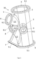
- FIG. 1 a schematic, perspective view or an exploded view of individual parts (1, 2, 3) for producing a node element (10) is shown at a first point in time.
- the node element (10) to be produced is made from several parts (1, 2, 3), one part (1) being made in one piece in the form of a partial shell and at least one connecting element (1.1, 1.2, 1.3, 3) running radially outwards. comprises, wherein the at least one radially outwardly extending connecting element (1.1, 1.2, 1.3) is made in one piece with the partial shell (1).
- the partial shell (1) consists of a forged part or preferably a cast part.
- a further radially outwardly extending connecting element (1.3) is provided in one piece, which extends transversely to the partial shell (1). Furthermore, at least one connecting element (3) extending radially outwards is provided as a separate part, which is materially connected to the node element (10), cf. Figure 2 .
- the connecting elements (1.1, 1.2, 1.3, 3) each have an end edge (1.11, 1.21, 1.31, 3.1) for materially connecting each with a flange (6, 7, 8, 9) as a separate part, cf. Figure 3 .
- the partial shell (2) which consists of a rolled and in particular shaped sheet metal, serves as a further part.
- the dimensioning of the partial shells (1, 2) and the connecting elements (1.1, 1.2, 1.3, 3) or their diameter and thickness depends on the design of the lattice structure (100) to be created, cf. Figure 4 .
- FIG 2 is a schematic, perspective view of a not yet completely created node element (10) shown at a second point in time, a material connection being made via the two longitudinal edges (1.4) of the partial shell (1) and the two longitudinal edges (2.1) of the partial shell (2). is, which in particular are each designed as longitudinal weld seams (2.3), so that the two partial shells (1, 2) form a hollow profile when connected form. Furthermore, at least one connecting element (3) running radially outwards is cohesively connected to the node element (10) as a separate part.
- FIG 3 a schematic, perspective representation of a node element (10) is shown.
- the node element (10) has a flange (4, 5) with through openings (4.1, 5.1) at each of its ends along its longitudinal extent, which are cohesively connected as separate parts to the end edges (1.5, 2.2) of the node element (10).
- the connecting elements (1.1, 1.2, 1.3, 3) also have flanges (6, 7, 8, 9) with through openings (6.1, 7.1, 8.1, 9.1), which are separate parts on corresponding end edges (1.11, 1.21, 1.31, 3.1) of the node element (10) or the connecting elements (1.1, 1.2, 1.3, 3) are cohesively connected.
- the node element (10) is designed as a forged sheet metal welding element or preferably as a cast sheet metal welding element. It is also conceivable that the node element (10) including all flanges (4, 5, 6, 7, 8) with the exception of at least one connecting element (3) running radially outwards and the flange (9) are completely made up as separate, connectable parts Cast or made from a fiber-reinforced plastic.
- the connecting elements (1.1, 1.2) are designed to connect diagonal struts (30) or one of their ends and the connecting elements (1.3, 3) are designed to connect the cross struts (40) or one of their ends.
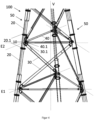
- FIG 4 is a schematic, perspective view of a grid structure (100) for a tower of a wind turbine, not shown, according to an embodiment of the invention.
- the lattice structure for a tower of a wind turbine comprises at least three corner posts (50), which are inclined to one another at an angle to the vertical (V) of the lattice structure (100), the corner posts (50) continuing in the lower part of the lattice structure (100). are spaced apart from each other than in the upper part of the lattice structure (100), each corner post (50) being composed of several longitudinal struts (20).
- the lattice structure further comprises at least one cross strut (40), which is arranged in a horizontal plane (E1, E2) of the lattice structure (100) between two corner posts (50) and is connected to them.
- the different levels (E1, E2) are each symbolized by the dashed lines.
- the lattice structure (100) comprises at least one diagonal strut (30), which is arranged between two horizontal planes (E1, E2) of the lattice structure (100) between two corner posts (50) and is connected to these.
- the lattice structure (100) comprises at least three node elements (10), which are arranged in at least one horizontal plane (E1, E2) of the lattice structure (100) between the longitudinal struts (20) forming the corner posts (50) and each act as a connecting element between two longitudinal struts (20), the at least one cross strut (40) and the at least one diagonal strut (30).
- the two longitudinal struts (20) to be connected at their ends to the node element (10) also each have a flange (20.1) with through openings, with joining elements (not shown), for example screw-nut connections, passing through or in the through openings (4.1, 5.1) are recorded, via which the node element (10) is mechanically connected to the longitudinal struts (20).
- the cross strut (40) and diagonal strut (3) to be connected at their end to the node element (10) each have a flange (30.1, 40.1) with through openings, with joining elements (not shown), for example screw-nut connections, passing through which or are accommodated in the through openings (6.1, 7.1, 8.1, 9.1), via which the node element (10) is mechanically connected to the cross strut (40) and the diagonal strut (30).
- joining elements not shown
- joining elements for example screw-nut connections
- the tower, not shown, of a wind turbine can comprise an upper part in the form of a cylindrical tubular tower, a lower part in the form of a lattice structure (100) according to an embodiment according to the invention and a middle part, the middle part connecting the upper part with the lower part (100).
- the tower, not shown, of a wind turbine, not shown, can be designed for the onshore or offshore area.
Landscapes
- Engineering & Computer Science (AREA)
- Chemical & Material Sciences (AREA)
- Architecture (AREA)
- Life Sciences & Earth Sciences (AREA)
- Mechanical Engineering (AREA)
- Combustion & Propulsion (AREA)
- Sustainable Energy (AREA)
- General Engineering & Computer Science (AREA)
- Materials Engineering (AREA)
- Wood Science & Technology (AREA)
- Sustainable Development (AREA)
- Civil Engineering (AREA)
- Structural Engineering (AREA)
- Wind Motors (AREA)
Description
Die Erfindung betrifft eine Gitterstruktur für einen Turm einer Windenergieanlage, umfassend:
- mindestens drei Eckstiele, welche in einem Winkel zur Vertikalen der Gitterstruktur zueinander geneigt sind, wobei die Eckstiele im unteren Teil der Gitterstruktur weiter voneinander beabstandet sind als im oberen Teil der Gitterstruktur, wobei jeder Eckstiel aus mehreren Längsstreben zusammengesetzt ist,
- mindestens eine Querstrebe, welche in einer horizontalen Ebene der Gitterstruktur zwischen zwei Eckstielen angeordnet ist und mit diesen verbunden ist, und/oder
- mindestens eine Diagonalstrebe, welche zwischen zwei horizontalen Ebenen der Gitterstruktur zwischen zwei Eckstielen angeordnet ist und mit diesen verbunden ist,
- mindestens drei Knotenelemente, welche in mindestens einer horizontalen Ebene der Gitterstruktur jeweils zwischen den die Eckstiele bildenden Längsstreben angeordnet sind und jeweils als Verbindungselement zwischen zwei Längsstreben, der mindestens einen Querstrebe und/oder der mindestens einen Diagonalstrebe fungieren.
- at least three corner posts which are inclined to one another at an angle to the vertical of the lattice structure, the corner posts being further apart from one another in the lower part of the lattice structure than in the upper part of the lattice structure, each corner post being composed of several longitudinal struts,
- at least one cross strut, which is arranged in a horizontal plane of the lattice structure between two corner posts and is connected to them, and / or
- at least one diagonal strut, which is arranged between two horizontal planes of the lattice structure between two corner posts and is connected to them,
- at least three node elements, which are arranged in at least one horizontal plane of the lattice structure between the longitudinal struts forming the corner struts and each function as a connecting element between two longitudinal struts, the at least one cross strut and / or the at least one diagonal strut.
Des Weiteren betrifft die Erfindung einen Turm einer Windenergieanlage.The invention further relates to a tower of a wind turbine.
Türme für Windenergieanlagen sind aus dem Stand der Technik bekannt. Entweder bestehen sie aus einer reinen Gitterstruktur, vgl.
Eine gattungsgemäße Gitterkonstruktion ist aus der
Die Tragstruktur eines Turms respektive der Turm einer Windenergieanlage ist durch den unstetigen Wind und den damit verbundenen Windturbulenzen enormen dynamischen Kräften ausgesetzt, die einen erheblichen Einfluss auf die Ermüdungsfestigkeit und somit auf Lebensdauer solcher Strukturen haben. Insbesondere nehmen die Windturbulenzen mit zunehmender Höhe ab und wirken sich somit positiv auf das Ermüdungsverhalten und dadurch auf die Wirtschaftlichkeit der Gesamtanlage aus Turbine, Rotorblätter und Tragstruktur respektive Turm aus. Daher besteht hinsichtlich der Stand- und Betriebsfestigkeit Optimierungspotential.The supporting structure of a tower or the tower of a wind turbine is exposed to enormous dynamic forces due to the unsteady wind and the associated wind turbulence, which have a significant influence on the fatigue strength and thus on the service life of such structures. In particular, the wind turbulence decreases with increasing height and thus has a positive effect on the fatigue behavior and thus on the economic efficiency of the entire system consisting of the turbine, rotor blades and support structure or tower. There is therefore potential for optimization in terms of stability and operational stability.
Der Erfindung liegt somit die Aufgabe zu Grunde, eine Gitterstruktur für einen Turm einer Windenergieanlage bereitzustellen, welche standsicher und betriebsfest insbesondere für Windenergieanlagen mit großer Nabenhöhe auslegbar und/oder wirtschaftlich herstellbar ist.The invention is therefore based on the object of providing a lattice structure for a tower of a wind turbine, which can be designed and/or produced economically in a stable and operational manner, particularly for wind turbines with a large hub height.
Gelöst wird diese Aufgabe gemäß einer ersten Lehre durch eine Gitterstruktur mit den Merkmalen des Patentanspruchs 1. Gelöst wird diese Aufgabe gemäß einer zweiten Lehre durch einen Turm mit den Merkmalen des Patentanspruchs 8.According to a first teaching, this task is solved by a lattice structure with the features of
Erfindungsgemäß weisen das Knotenelement in Längserstreckung an seinen Enden jeweils einen Flansch mit Durchgangsöffnungen und die zwei an ihren Enden mit dem Knotenelement zu verbindenden Längsstreben jeweils einen Flansch mit Durchgangsöffnungen auf, wobei Fügeelemente durch die oder in den Durchgangsöffnungen aufgenommen sind, über welche das Knotenelement mit den Längsstreben mechanisch verbunden ist.According to the invention, the node element each has a flange with through openings at its ends in the longitudinal extent and the two longitudinal struts to be connected to the node element at their ends each have a flange with through openings, with joining elements being received through or in the through openings, via which the node element is connected to the Longitudinal struts are mechanically connected.
Eine mechanische Verbindung zwischen den Knotenelementen und den die Eckstiele der Gitterstruktur bildenden Längsstreben ermöglicht eine schnelle und somit eine wirtschaftliche Errichtung einer Gitterstruktur auf einer Baustelle. Dadurch lassen sich im Vergleich zum Stand der Technik stoffschlüssige Verbindungen, dementsprechender Schweißaufwand, während der Errichtung der Gitterstruktur auf der Baustelle reduzieren. Im Vergleich zum Stand der Technik bedarf es nicht aufgrund der großen und unterschiedlichen Abmessungen der zu verbauenden Teile, der unterschiedlichen Teiledicken und der damit einhergehenden Vielzahl an unterschiedlichen Verbindungselementen zu aufwändigen und in der Praxis oft ungenauen Schweißnahtvorbereitungen, so dass es im Bereich der Schweißkerben zu hohen, unerwünschten Spannungskonzentrationen kommen kann. Eine Optimierung der komplexen Schweißnahtvorbereitungen, beispielsweise mittels 3-D-CNC-Maschinen, stellt große Herausforderungen aufgrund der Fertigungstoleranzen der eingesetzten Teile mit unterschiedlichen Teilegrößen dar. Um derart große (Bau-)Teile schweißtechnisch händeln zu können, bedarf es entsprechend großer Schweißvorrichtungen. Des Weiterhin können eventuell auftretende Schweißnahtimperfektionen aufgrund der großen, komplexen Abmessungen nicht im Vorfeld berechnungsseitig exakt berücksichtigt werden. Dieser Umstand führt wiederum zu Unsicherheiten bei der Abschätzung der Lebensdauer. Zudem kann aufgrund der Größe der Verbindungen und der langen Produktionszeiten insbesondere auf der Baustelle eine reproduzierbare Nahtqualität nicht zuverlässig gewährleistet werden. Diese Nachteile treten bei der erfindungsgemäßen Gitterstruktur nicht auf.A mechanical connection between the node elements and the longitudinal struts forming the corner posts of the lattice structure enables a quick and therefore economical construction of a lattice structure on a construction site. This means that, compared to the prior art, cohesive connections and the corresponding welding effort can be reduced during the construction of the lattice structure on the construction site. In comparison to the state of the art, due to the large and different dimensions of the parts to be installed, the different part thicknesses and the associated multitude of different connecting elements, there is no need for complex and, in practice, often inaccurate weld seam preparations, so that there are too many weld notches in the area , undesirable stress concentrations can occur. An optimization of the complex weld seam preparations, For example, using 3D CNC machines, represents major challenges due to the manufacturing tolerances of the parts used with different part sizes. In order to be able to weld such large (component) parts, correspondingly large welding devices are required. Furthermore, any weld seam imperfections that may occur cannot be precisely taken into account in advance in the calculation due to the large, complex dimensions. This circumstance in turn leads to uncertainties when estimating the service life. In addition, due to the size of the connections and the long production times, reproducible seam quality cannot be reliably guaranteed, especially on the construction site. These disadvantages do not occur with the lattice structure according to the invention.
Durch die entsprechende Ausgestaltung und mechanische Verbindung zwischen dem bzw. den Knotenelement(en) und den Längsstreben, sowie die angebundenen Querstrebe(n) und/ oder Diagonalstrebe(n), insbesondere durch das Zusammenwirken aller Knotenelemente kann die Gitterstruktur für einen Turm einer Windenergieanlage optimal an die am Erstellungsort hohen dynamischen Belastungen, insbesondere auch für zyklische Betriebslasten ausgelegt werden. Dadurch sind Windenergieanlagen mit großer Nabenhöhe auslegbar und/oder wirtschaftlich herstellbar. Unter Nabenhöhe ist die Nabe des Windrotors der Windenergieanlage über der Geländeoberfläche (Aufstellungsort) zu verstehen.Through the appropriate design and mechanical connection between the node element(s) and the longitudinal struts, as well as the connected cross strut(s) and/or diagonal strut(s), in particular through the interaction of all node elements, the lattice structure can be optimal for a tower of a wind turbine be designed for the high dynamic loads at the production site, especially for cyclic operating loads. This means that wind turbines with large hub heights can be designed and/or produced economically. Hub height means the hub of the wind turbine's wind rotor above the terrain surface (installation site).
Die Längsstrebe, die Querstrebe und die Diagonalstrebe können aus Profilen gebildet sein, entweder jeweils aus einem Hohlprofil oder aus einem Vollmaterial oder einer Kombination daraus bestehen. Der Querschnitt der Profile kann individuell ausgebildet sein. Die Längsstrebe hat insbesondere einen größeren Durchmesser im Vergleich zur Querstrebe und/oder Diagonalstrebe. Wird ein Hohlprofil verwendet, ist es beispielsweise ein längs- oder ein spiralnahtgeschweißtes Rohr. Besonders bevorzugt weisen Längsstrebe, Querstrebe und Diagonalstrebe einen kreisrunden Querschnitt auf. Weiter bevorzugt können die Profile standardisierte Profile sein, die kostengünstig herstellbar sind und dadurch je nach Ausgestaltung der Gitterstruktur individuell auf die gewünschte Länge zuschneidbar sind.The longitudinal strut, the cross strut and the diagonal strut can be formed from profiles, either each consisting of a hollow profile or of a solid material or a combination thereof. The cross section of the profiles can be designed individually. The longitudinal strut in particular has a larger diameter compared to the cross strut and/or diagonal strut. If a hollow profile is used, it is, for example, a longitudinally or spirally welded pipe. Particularly preferably, the longitudinal strut, cross strut and diagonal strut have a circular cross section. More preferably, the profiles can be standardized profiles that can be produced inexpensively and can therefore be individually cut to the desired length depending on the design of the lattice structure.
Jeder der mindestens drei Eckstiele ist aus mindestens zwei oder mehreren Längsstreben zusammengesetzt, wobei zwischen jeweils zwei Längsstreben erfindungsgemäß jeweils ein Knotenelement über Flansche mechanisch verbunden ist. Die Gitterstruktur kann genau drei Eckstiele aber auch mehr als drei Eckstiele aufweisen.Each of the at least three corner supports is composed of at least two or more longitudinal struts, with a node element being mechanically connected via flanges between each two longitudinal struts. The lattice structure can have exactly three corner posts but also more than three corner posts.
Unter unterem Teil der Gitterstruktur ist der boden- oder gründungsnahe Bereich der Gitterstruktur gemeint und unter oberem Teil der Gitterstruktur ist der gegenüberliegende und somit boden- oder gründungsferne Bereich der Gitterstruktur gemeint. Die Eckstiele sind in einem Winkel zur Vertikalen der Gitterstruktur zueinander geneigt, was bedeutet, dass sich die Gitterstruktur vom unteren zum oberen Teil der Gitterstruktur hin verjüngt.The lower part of the lattice structure means the area of the lattice structure close to the ground or foundation and the upper part of the lattice structure means the area of the lattice structure that is opposite and therefore far from the ground or foundation. The corner posts are inclined towards each other at an angle to the vertical of the lattice structure, which means that the lattice structure tapers from the lower to the upper part of the lattice structure.
Die Vertikale eines Gitterturms und die mindestens eine horizontale Ebene der Gitterstruktur beziehen sich auf den Zustand einer zusammengebauten respektive errichteten Gitterstruktur.The vertical of a lattice tower and the at least one horizontal plane of the lattice structure refer to the state of an assembled or constructed lattice structure.
Je nach Ausgestaltung der Gitterstruktur kann mindestens eine Querstrebe vorhanden sein, welche in einer horizontalen Ebene der Gitterstruktur zwischen zwei Eckstielen angeordnet und mit diesen verbunden ist. Je nach Ausführung der Gitterstruktur kann alternativ oder zusätzlich mindestens eine Diagonalstrebe vorhanden sein, welche zwischen zwei horizontalen Ebenen der Gitterstruktur, welche in der Vertikalen der Gitterstruktur beabstandet voneinander vorgesehen sind, zwischen zwei Eckstielen angeordnet und mit diesen verbunden sein. Je nach Anzahl der Eckstiele können bei Bedarf auch die gleiche Anzahl an Querstreben verwendet werden, was bedeutet, dass bei drei Eckstielen auch drei Querstreben in jeweils einer horizontalen Ebene der Gitterstruktur jeweils zwischen den Eckstielen angeordnet und mit diesen verbunden sein können.Depending on the design of the lattice structure, at least one cross strut can be present, which is arranged in a horizontal plane of the lattice structure between two corner posts and is connected to them. Depending on the design of the lattice structure, at least one diagonal strut can alternatively or additionally be present, which is arranged between two horizontal planes of the lattice structure, which are spaced apart from one another in the vertical of the lattice structure, between two corner posts and is connected to them. Depending on the number of corner posts, the same number of crossbars can be used if necessary, which means that with three corner posts, three crossbars can also be arranged in a horizontal plane of the lattice structure between the corner posts and connected to them.
Die mindestens drei Knotenelemente sind in mindestens einer horizontalen Ebene der Gitterstruktur jeweils zwischen den die Eckstiele bildenden Längsstreben angeordnet und fungieren jeweils als Verbindungselement zwischen zwei Längsstreben, der mindestens einen Querstrebe und/oder der mindestens einen Diagonalstrebe. Je nach Anzahl der Eckstiele sind auch eine entsprechende Anzahl an Knotenelementen in mindestens einer horizontalen Ebene der Gitterstruktur vorgesehen. Je nach Ausgestaltung der Gitterstruktur können Knotenelemente in zwei oder mehr als zwei horizontale Ebenen der Gitterstruktur vorgesehen sein, wobei die Anzahl der Knotenelemente aus dem Produkt der Anzahl der horizontalen Ebenen und der Anzahl der Eckstiele bestimmt wird. Bedeutet beispielsweise, dass bei drei Eckstielen und drei horizontalen Ebenen insgesamt neun Knotenelemente benötigt werden, welche als Verbindungselemente für Längsstreben, Querstreben und/oder Diagonalstreben fungieren.The at least three node elements are arranged in at least one horizontal plane of the lattice structure between the longitudinal struts forming the corner struts and each act as a connecting element between two longitudinal struts, the at least one cross strut and / or the at least one diagonal strut. Depending on the number of corner posts, a corresponding number of node elements are also provided in at least one horizontal plane of the lattice structure. Depending on the design of the lattice structure, node elements can be provided in two or more than two horizontal levels of the lattice structure, the number of node elements being determined from the product of the number of horizontal levels and the number of corner posts. For example, this means that with three corner supports and three horizontal levels, a total of nine node elements are required, which act as connecting elements for longitudinal struts, cross struts and/or diagonal struts.
Unter Durchgangsöffnungen sind beispielsweise Bohrungen zu verstehen, welche eine Aufnahme und/oder ein Durchschieben von Fügeelementen ermöglichen.Through openings are understood to mean, for example, bores which enable joining elements to be received and/or pushed through.
Weitere vorteilhafte Ausgestaltungen und Weiterbildungen gehen aus der nachfolgenden Beschreibung hervor. Ein oder mehrere Merkmale aus den Ansprüchen, der Beschreibung wie auch der Zeichnung können mit einem oder mehreren anderen Merkmalen daraus zu weiteren Ausgestaltungen der Erfindung verknüpft werden. Es können auch ein oder mehrere Merkmale aus den unabhängigen Ansprüchen durch ein oder mehrere andere Merkmale verknüpft werden.Further advantageous refinements and further developments can be found in the following description. One or more features from the claims, the description and the drawing can be combined with one or more other features from them to form further embodiments of the invention. One or more features from the independent claims can also be linked by one or more other features.
Gemäß einer Ausgestaltung der erfindungsgemäßen Gitterstruktur umfasst das Knotenelement mindestens ein radial nach außen verlaufendes Anbindungselement, welches zur Anbindung der mindestens einen Querstrebe und/oder der mindestens einen Diagonalstrebe fungiert. Je nach Ausgestaltung der Gitterstruktur erfolgt eine Anbindung mindestens einer Querstrebe bzw. ein Ende einer Querstrebe und/oder mindestens einer Diagonalstrebe bzw. ein Ende einer Diagonalstrebe über mindestens ein radial nach außen verlaufendes Anbindungselement am Knotenelement. Das Knotenelement kann zwei oder mehr als zwei radial nach außen verlaufende Anbindungselemente aufweisen, so dass mindestens eine Querstrebe bzw. ein Ende einer Querstrebe und mindestens eine Diagonalstrebe bzw. ein Ende einer Diagonalstrebe oder mindestens zwei Querstreben bzw. jeweils ein Ende der zwei Querstreben und/oder mindestens zwei Diagonalstreben bzw. jeweils ein Ende der zwei Diagonalstreben an das Knotenelement angebunden werden können.According to one embodiment of the lattice structure according to the invention, the node element comprises at least one connecting element extending radially outwards, which functions to connect the at least one cross strut and/or the at least one diagonal strut. Depending on the design of the lattice structure, at least one cross strut or one end of a cross strut and / or at least one diagonal strut or one end of a diagonal strut is connected via at least one connecting element running radially outwards to the node element. The node element can have two or more than two connecting elements extending radially outwards, so that at least one cross strut or one end of a cross strut and at least one diagonal strut or one end of a diagonal strut or at least two cross struts or one end of each of the two cross struts and / or at least two diagonal struts or one end of the two diagonal struts can be connected to the node element.
Gemäß einer Ausgestaltung der erfindungsgemäßen Gitterstruktur weist das mindestens eine Anbindungselement einen Flansch mit Durchgangsöffnungen und die an ihrem Ende mit dem Knotenelement zu verbindende Querstrebe und/oder Diagonalstrebe jeweils einen Flansch mit Durchgangsöffnungen auf, wobei Fügeelemente durch die oder in den Durchgangsöffnungen aufgenommen sind, über welche das Knotenelement mit der Querstrebe und/oder Diagonalstrebe mechanisch verbunden ist. Dies ist insbesondere vorteilhaft, da die Errichtung der Gitterstruktur zum größten Teil über mechanische Verbindungen zwischen den einzelnen Komponenten (Längsstreben, Querstreben, Diagonalstreben, Knotenelemente) schnell und somit wirtschaftlich vor Ort ermöglicht wird. Dadurch kann die Errichtung der Gitterstruktur durch den Zusammenbau der einzelnen Komponenten auch einfacher Art und Weise in der Vertikalen vonstattengehen, wodurch gegenüber einem liegenden horizontalen Zusammenbau, bedingt durch zum größten Teil stoffschlüssig zu verbindende Komponenten und somit verbunden einem erhöhten Schweißaufwand auf der Baustelle, insbesondere kein Schwerlastkran zum Aufrichten benötigt wird.According to one embodiment of the lattice structure according to the invention, the at least one connecting element has a flange with through openings and the cross strut and/or diagonal strut to be connected to the node element at its end each has a flange with through openings, with joining elements being received through or in the through openings, via which the node element is mechanically connected to the cross strut and/or diagonal strut. This is particularly advantageous because the construction of the lattice structure is largely made possible quickly and economically on site via mechanical connections between the individual components (longitudinal struts, cross struts, diagonal struts, node elements). As a result, the construction of the lattice structure can also be carried out in a simpler manner by assembling the individual components vertically, which means that compared to a lying horizontal assembly, due to components that are largely to be connected in a materially bonded manner and thus associated with an increased welding effort on the construction site, in particular no Heavy duty crane is required for erection.
Das Knotenelement ist aus mehreren Teilen gefertigt, wobei ein Teil einstückig in Form einer Teilschale gefertigt ist und dieses mindestens ein radial nach außen verlaufendes Anbindungselement umfasst. Vorzugsweise besteht diese Teilschale aus einem Gussteil oder Schmiedeteil. Des Weiteren können einstückige Teile individuell skalierbar sein. Dies kann insbesondere vorteilhaft sein, um die Herstellung des Knotenelements und damit verbunden auch die Herstellung der Gitterstruktur möglichst effizient und kostengünstig, vorzugsweise in Serie unter Sicherstellung einer möglichst hohen gleichbleibenden Qualität zu ermöglichen.The node element is made of several parts, one part being made in one piece in the form of a partial shell and comprising at least one connecting element running radially outwards. This partial shell preferably consists of a cast part or forged part. Furthermore, one-piece parts can be individually scalable. This can be particularly advantageous in order to enable the production of the node element and, associated therewith, the production of the lattice structure as efficiently and cost-effectively as possible, preferably in series, while ensuring the highest possible consistent quality.
Erfindungsgemäß ist das Knotenelement aus mehreren Teilen gefertigt, wobei ein Teil einstückig in Form einer Teilschale (erste Teilschale) gefertigt ist und ein mindestens radial nach außen verlaufendes Anbindungselement umfasst, wobei die Teilschale zwei Längskanten umfasst, über welche mindestens ein weiteres Teil in Form einer Teilschale (zweite Teilschale) mit zwei Längskanten stoffschlüssig verbunden ist, wobei die beiden Teilschalen im verbundenen Zustand ein Hohlprofil bilden. Vorzugsweise besteht die (erste) Teilschale aus einem Gussteil oder Schmiedeteil. Dadurch kann eine (erste) Teilschale insbesondere effizient und kostengünstig, vorzugsweise in Serie mit einer hohen gleichbleibenden Qualität hergestellt werden. Des Weiteren können einstückige Teile individuell skalierbar sein. Bevorzugt besteht die (zweite) Teilschale aus einem gewalzten und insbesondere geformten Blech. Gewalzte Bleche sind in allen möglichen Dicken verfügbar und lassen sich kostengünstig zu Teilschalen formen. Weiter bevorzugt besteht das gewalzte Blech aus einem Stahlwerkstoff. Besonders bevorzugt ist das Knotenelement als Guss-Blech-Schweißelement oder Schmiede-Blech-Schweißelement ausgeführt. Die erste Teilschale kann in ihrer Längserstreckung je nach Anordnung des oder der radial nach außen verlaufenden Anbindungselemente insbesondere jeweils an ihren Enden einen Querschnitt aufweisen, welcher maximal ein ¾-Bogenmaß eines kreisrunden Querschnitts, insbesondere maximal ein ½-Bogenmaß eines kreisrunden Querschnitts, vorzugsweise maximal ein 1/3-Bogenmaß eines kreisrunden Querschnitts einnehmen kann. Durch die stoffschlüssige Verbindung mit der zweiten Teilschale wird der kreisrunde Querschnitt an den jeweiligen Enden komplettiert. Bevorzugt weist die zweite Teilschale an ihren Enden ein größeres Bogenmaß als die erste Teilschale auf.According to the invention, the node element is made from several parts, with one part being made in one piece in the form of a partial shell (first partial shell) and comprising a connecting element that extends at least radially outwards, the partial shell comprising two longitudinal edges, over which at least one further part in the form of a partial shell (second partial shell) is cohesively connected to two longitudinal edges, the two partial shells forming a hollow profile in the connected state. The (first) partial shell preferably consists of a cast part or forged part. As a result, a (first) partial shell can be produced particularly efficiently and cost-effectively, preferably in series, with a high, consistent quality. Furthermore, one-piece parts can be individually scalable. The (second) partial shell preferably consists of a rolled and in particular shaped sheet metal. Rolled sheets are available in all possible thicknesses and can be formed into partial shells cost-effectively. More preferably, the rolled sheet consists of a steel material. The node element is particularly preferably designed as a cast sheet metal welding element or forged sheet metal welding element. In its longitudinal extent, depending on the arrangement of the radially outwardly extending connecting element(s), the first partial shell can have a cross section, in particular at each of its ends, which is a maximum of ¾ radian of a circular cross section, in particular a maximum of ½ radian of a circular cross section, preferably a maximum of one Can take up 1/3 radian of a circular cross section. The circular cross section is completed at the respective ends by the cohesive connection with the second partial shell. The second sub-shell preferably has a larger radian dimension at its ends than the first sub-shell.
Insbesondere ist die einstückige Herstellung eines Teils des Knotenelements gut und mit hoher, gleichbleibender Qualität, insbesondere in Serie reproduzierbar. Neben Guss oder Schmieden ist auch die Verwendung eines faserverstärkten Kunststoffs (Glasfaser, Kohlenstofffaser) zur Herstellung eines Teils oder des im Wesentlichen vollständigen Knotenelements möglich, welches in geeigneten Vorrichtungen beispielsweise im RTM-Verfahren herstellbar ist.In particular, the one-piece production of a part of the node element good and with high, consistent quality, particularly reproducible in series. In addition to casting or forging, the use of a fiber-reinforced plastic (glass fiber, carbon fiber) to produce a part or the essentially complete node element possible, which can be produced in suitable devices, for example using the RTM process.
Das beispielsweise aus mindestens zwei Teilschalen zusammengesetzte Knotenelement hat insbesondere den Vorteil, dass das mindestens eine radial nach außen verlaufende Anbindungselement einstückig mit der ersten Teilschale gefertigt ist, vorzugsweise als Gussteil ausgeführt ist und damit eine besonders stabile und steife Anbindung der Querstrebe(n) und/oder Diagonalstrebe(n) ermöglicht und die zweite Teilschale aus einem gewalzten und insbesondere geformten Blech das Knotenelement mit einem relativ günstigen und formtechnisch relativ einfach herstellbaren Werkstoff komplettiert, wobei die beiden Teilschalen jeweils über ihre zwei Längskanten stoffschlüssig verbunden sind und dadurch ein Hohlprofil bilden. Durch die stoffschlüssige Verbindung insbesondere in Form jeweils einer Längsschweißnaht, werden größere Rundungsradien in den Spannungs-Hot-Spot Bereichen ermöglicht. Dadurch können Bereiche und/oder Zonen, beispielsweise Ecken und/oder Kanten, in denen sich die Spannungen konzentrieren, demnach hohe Spannungszustände und/oder -spitzen auftreten können, durch möglichst gleichmäßig verlaufende (Aus-)Rundungen Spannungen reduziert werden, was sich positiv auf die Lebensdauer auswirken kann. Des Weiteren können dadurch an den Spannungs-Hot-Spot-Bereichen höhere Kerbfallklassen erzielt werden, wobei der Kerbfall die zulässige Spannung beschreibt, die unter Betriebslasten nicht überschritten werden darf, quasi dadurch höhere Ermüdungsfestigkeiten erzielt werden können, was sich wiederum positiv auf die Kosten auswirken kann. Insbesondere kann die Längsschweißnaht bzw. können die Längsschweißnähte entlang des Kraftflusses zu einer hohen Dauerfestigkeit beitragen und darüber hinaus ebenfalls zu einer höheren Kerbfallklasse führen.The node element, for example composed of at least two partial shells, has the particular advantage that the at least one connecting element running radially outwards is made in one piece with the first partial shell, is preferably designed as a cast part and thus provides a particularly stable and rigid connection of the cross strut(s) and/or or diagonal strut (s) and the second partial shell made of a rolled and in particular shaped sheet metal completes the node element with a relatively inexpensive material that is relatively easy to produce in terms of shape, the two partial shells each being cohesively connected via their two longitudinal edges and thereby forming a hollow profile. The cohesive connection, particularly in the form of a longitudinal weld seam, enables larger curvature radii in the stress hot spot areas. As a result, areas and/or zones, for example corners and/or edges, in which the stresses are concentrated, meaning that high stress states and/or peaks can occur, can be reduced by rounding (roundings) that are as even as possible, which has a positive effect can affect the lifespan. Furthermore, higher notch fall classes can be achieved at the stress hot spot areas, whereby the notch fall describes the permissible stress that must not be exceeded under operating loads, so that higher fatigue strengths can be achieved, which in turn has a positive effect on costs can. In particular, the longitudinal weld seam or longitudinal weld seams along the force flow can contribute to a high fatigue strength and also lead to a higher notch case class.
Gemäß einer Ausgestaltung der erfindungsgemäßen Gitterstruktur ist mindestens ein radial nach außen verlaufendes Anbindungselement als separates Teil stoffschlüssig mit dem Knotenelement verbunden. Toleranzbedingt kann auftreten, dass insbesondere nicht alle radial nach außen verlaufenden Anbindungselemente vorzugsweise einstückig mit einem Teil des Knotenelements oder des im Wesentlichen vollständigen Knotenelements herstellbar sind, so dass das mindestens eine radial nach außen verlaufende Anbindungselement als separates Teil individuell an die Einbausituation stoffschlüssig an das Knotenelement verbindbar ist. Dadurch würde sich der Aufwand des Zusammenbaus zwar geringfügig erhöhen, bliebe dennoch im Rahmen und es könnte auf die Einbausituation korrigierend eingewirkt werden. Des Weiteren können dadurch, wenn beispielsweise kein symmetrischer Aufbau in der Gitterstruktur umgesetzt wird, insbesondere in mindestens einer horizontalen Ebene der Gitterstruktur mindestens zwei unterschiedliche Knotenelemente berücksichtigt werden, die sich lediglich in der Anordnung des mindestens einen radial nach außen verlaufenden Anbindungselements unterscheiden, welches als separates Teil ausgeführt ist, so dass das Knotenelement oder Teile des Knotenelements als Gleichteil(e) in einer Serienfertigung, insbesondere als Massenprodukt, kostengünstig und gleichzeitig mit einer Qualität auf einem gleichbleibend hohen Niveau hergestellt werden kann. Je nach Ausgestaltung der Gitterstruktur können durch die Individualisierung respektive die Skalierung der Knotenelemente unterschiedliche Klassen von Windturbinen und unterschiedliche Nabenhöhen realisiert werden.According to one embodiment of the lattice structure according to the invention, at least one connecting element running radially outwards is connected to the node element as a separate part in a materially bonded manner. Due to tolerances, it can happen that in particular not all connecting elements extending radially outwards can preferably be produced in one piece with a part of the node element or the essentially complete node element, so that the at least one connecting element extending radially outwards can be individually bonded to the node element as a separate part to suit the installation situation is connectable. This would increase the effort involved in assembling slightly, but it would still be within limits and the installation situation could be corrected. Furthermore, if, for example, no symmetrical structure is implemented in the lattice structure, in particular in at least one horizontal plane of the lattice structure two different node elements are taken into account, which only differ in the arrangement of the at least one connecting element running radially outwards, which is designed as a separate part, so that the node element or parts of the node element are used as identical part(s) in series production, in particular as a mass product, can be produced cost-effectively and at the same time with a consistently high level of quality. Depending on the design of the grid structure, different classes of wind turbines and different hub heights can be realized through the individualization or scaling of the node elements.
Gemäß einer Ausgestaltung der erfindungsgemäßen Gitterstruktur ist der mindestens eine Flansch als separates Teil an einer korrespondierenden Stirnkante des Knotenelements stoffschlüssig verbunden. Alternativ zu einer Ausführung, welche einen Flansch oder mehrere Flansche einstückig mit dem einen oder mehreren radial nach außen verlaufenden Anbindungselement(en) umfasst, können durch die separaten Flansch(teile) einfach und kostengünstig hergestellt werden. Beispielsweise ist der separate Flansch gegossen.According to one embodiment of the lattice structure according to the invention, the at least one flange is cohesively connected as a separate part to a corresponding end edge of the node element. As an alternative to an embodiment which comprises a flange or several flanges in one piece with the one or more connecting element(s) extending radially outwards, the separate flange(parts) can be produced easily and cost-effectively. For example, the separate flange is cast.
Gemäß einem zweiten Aspekt betrifft die Erfindung einen Turm einer Windenergieanlage mit einem Oberteil in Form eines zylindrischen Rohrturms, einem Unterteil in Form einer erfindungsgemäßen Gitterstruktur und einem Mittelteil, welches das Oberteil mit dem Unterteil verbindet. Das Mittelteil fungiert als Übergangsstück zwischen Unter- und Oberteil des Turms einer Windenergieanlage.According to a second aspect, the invention relates to a tower of a wind turbine with an upper part in the form of a cylindrical tubular tower, a lower part in the form of a lattice structure according to the invention and a middle part which connects the upper part to the lower part. The middle section acts as a transition piece between the lower and upper sections of the tower of a wind turbine.
Um Wiederholungen zu vermeiden, wird auf die vorteilhaften Ausgestaltungen der erfindungsgemäßen Gitterstruktur verwiesen.In order to avoid repetition, reference is made to the advantageous embodiments of the lattice structure according to the invention.
Im Folgenden wird die Erfindung anhand von Zeichnungen näher erläutert. Gleiche Teile sind mit gleichen Bezugszeichen versehen. Im Einzelnen zeigen:
- Fig. 1
- eine schematische, perspektivische Darstellung einzelner Teile zur Erzeugung eines Knotenelements zu einem ersten Zeitpunkt,
- Fig. 2
- eine schematische, perspektivische Darstellung eines noch nicht vollständig erzeugten Knotenelements zu einem zweiten Zeitpunkt,
- Fig. 3
- eine schematische, perspektivische Darstellung eines Knotenelements und
- Fig. 4
- eine schematische, perspektivische Darstellung einer Gitterstruktur gemäß einer Ausführung der Erfindung.
- Fig. 1
- a schematic, perspective representation of individual parts for creating a node element at a first point in time,
- Fig. 2
- a schematic, perspective representation of a node element that has not yet been completely created at a second point in time,
- Fig. 3
- a schematic, perspective representation of a node element and
- Fig. 4
- a schematic, perspective representation of a lattice structure according to an embodiment of the invention.
In
In
In
Die Anbindungselemente (1.1, 1.2) sind zur Anbindung von Diagonalstreben (30) respektive eines ihrer Enden und die Anbindungselemente (1.3, 3) zur Anbindung der Querstreben (40) respektive eines ihrer Enden ausgelegt.The connecting elements (1.1, 1.2) are designed to connect diagonal struts (30) or one of their ends and the connecting elements (1.3, 3) are designed to connect the cross struts (40) or one of their ends.
In
Auch die zwei an ihren Enden mit dem Knotenelement (10) zu verbindenden Längsstreben (20) weisen jeweils einen Flansch (20.1) mit Durchgangsöffnungen auf, wobei nicht dargestellte Fügeelemente, beispielsweise Schrauben-Mutter-Verbindungen, durch die oder in den Durchgangsöffnungen (4.1, 5.1) aufgenommen sind, über welche das Knotenelement (10) mit den Längsstreben (20) mechanisch verbunden ist.The two longitudinal struts (20) to be connected at their ends to the node element (10) also each have a flange (20.1) with through openings, with joining elements (not shown), for example screw-nut connections, passing through or in the through openings (4.1, 5.1) are recorded, via which the node element (10) is mechanically connected to the longitudinal struts (20).
Des Weiteren weisen auch die an ihrem Ende mit dem Knotenelement (10) zu verbindende Querstrebe (40) und Diagonalstrebe (3) jeweils einen Flansch (30.1, 40.1) mit Durchgangsöffnungen auf, wobei nicht dargestellte Fügeelemente, beispielsweise Schrauben-Mutter-Verbindungen, durch die oder in den Durchgangsöffnungen (6.1, 7.1, 8.1, 9.1) aufgenommen sind, über welche das Knotenelement (10) mit der Querstrebe (40) und der Diagonalstrebe (30) mechanisch verbunden ist. Denkbar ist auch, dass abhängig von der Ausgestaltung der Gitterstruktur auch nur Querstreben oder nur Diagonalstreben vorgesehen sind, so dass die Knotenelemente entsprechende auf den Bedarfsfall angepasste nach radial nach außen verlaufende Anbindungselemente berücksichtigen, nicht dargestellt.Furthermore, the cross strut (40) and diagonal strut (3) to be connected at their end to the node element (10) each have a flange (30.1, 40.1) with through openings, with joining elements (not shown), for example screw-nut connections, passing through which or are accommodated in the through openings (6.1, 7.1, 8.1, 9.1), via which the node element (10) is mechanically connected to the cross strut (40) and the diagonal strut (30). It is also conceivable that, depending on the design of the lattice structure, only cross struts or only diagonal struts are provided, so that the node elements take into account corresponding radially outwardly extending connecting elements adapted to the requirements, not shown.
Der nicht dargestellte Turm einer nicht dargestellten Windenergieanlage kann ein Oberteil in Form eines zylindrischen Rohrturms, ein Unterteil in Form einer Gitterstruktur (100) nach einer erfindungsgemäßen Ausführung und einen Mittelteil umfassen, wobei das Mitteilteil das Oberteil mit dem Unterteil (100) verbindet.The tower, not shown, of a wind turbine, not shown, can comprise an upper part in the form of a cylindrical tubular tower, a lower part in the form of a lattice structure (100) according to an embodiment according to the invention and a middle part, the middle part connecting the upper part with the lower part (100).
Der nicht dargestellte Turm einer nicht dargestellten Windenergieanlage kann für den Onshore- oder Offshore-Bereich ausgelegt sein.The tower, not shown, of a wind turbine, not shown, can be designed for the onshore or offshore area.
Die beschriebenen Merkmale sind alle, soweit technisch möglich, miteinander kombinierbar.The features described can all be combined with one another as far as technically possible.
Claims (8)
- Lattice structure (100) for a tower of a wind power installation, comprising- at least three corner posts (50) which are mutually inclined at an angle in relation to the vertical (V) of the lattice structure (100), wherein the corner posts (50) in the lower part of the lattice structure (100) are further spaced apart from one another than in the upper part of the lattice structure (100), wherein each corner post (50) is assembled from a plurality of longitudinal struts (20),- at least one cross strut (40) which is disposed in a horizontal plane (E1, E2) of the lattice structure (100) between two corner posts (50) and is connected to the latter, and/or- at least one diagonal strut (30) which is disposed between two horizontal planes (E1, E2) of the lattice structure (100) between two corner posts (50) and is connected to the latter,- at least three node elements (10) which are disposed in at least one horizontal plane (E1, E2) of the lattice structure (100), in each case between the longitudinal struts (20) forming the corner posts (50), and in each case function as a connecting element between two longitudinal struts (20), the at least one cross strut (40), and/or at least one diagonal strut (30),characterized in that the node element (10) in the longitudinal extent on the ends thereof has in each case one flange (4, 5) with passage openings (4.1, 5.1), and the two longitudinal struts (20) which at the ends thereof are to be connected to the node element (10) have in each case one flange (20.1) with passage openings, wherein joining element by way of which the node element (10) is mechanically connected to the longitudinal struts (20) are received by way of or in the passage openings (4.1, 5.1), wherein the node element (10) is manufactured from a plurality of parts (1, 2, 3), wherein one part (1) is integrally manufactured in the form of a shell part and comprises at least one attachment element (1.1, 1.2, 1.3) which runs radially outwards, wherein the shell part (1) comprises two longitudinal edges (1.4) by way of which at least one further part (2) in the form of a shell part having two longitudinal edges (2.1) is connected in a materially integral manner, wherein the two shell parts (1, 2) in the connected state form a hollow section.
- Lattice structure according to Claim 1, wherein the attachment element (1.1, 1.2, 1.3, 3) which runs radially outwards serves for attaching the at least one cross strut (40) and/or the at least one diagonal strut (30).
- Lattice structure according to Claim 2, wherein the attachment element (1.1, 1.2, 1.3, 3) has a flange (6, 7, 8, 9) with passage openings (6.1, 7.1, 8.1, 9.1), and the cross strut (40) and/or diagonal strut (30) which at the end thereof are to be connected to the node element (10) have in each case one flange (30.1, 40.1) with passage openings, wherein joining elements by way of which the node element (10) is mechanically connected to the cross strut (40) and/or diagonal strut (30) are received by way of or in the passages openings (6.1, 7.1, 8.1, 9.1).
- Lattice structure according to Claim 1, wherein the shell part (1) is composed of a casting or a forging.
- Lattice structure according to Claim 1, wherein the shell part (1) is composed of a rolled and in particular formed metal sheet.
- Lattice structure according to one of the preceding claims, wherein at least one attachment element (3) which runs radially outwards as a separate part is connected to the node element (10) in a materially integral manner.
- Lattice structure according to one of the preceding claims, wherein the at least one flange (4, 5, 6, 7, 8, 9) as a separate part is connected in a materially integral manner on a corresponding leading edge (1.11, 1.21, 1.31, 1.5, 2.2, 3.1) of the node element (10).
- Tower of a wind power installation having an upper part in the form of a cylindrical tubular tower, a lower part in the form of a lattice structure (100) according to one of the preceding claims, and a central part which connects the upper part to the lower part (100).
Applications Claiming Priority (2)
| Application Number | Priority Date | Filing Date | Title |
|---|---|---|---|
| DE102019218358.1A DE102019218358A1 (en) | 2019-11-27 | 2019-11-27 | Lattice structure for a tower of a wind turbine and tower of a wind turbine |
| PCT/EP2020/082345 WO2021104931A1 (en) | 2019-11-27 | 2020-11-17 | Lattice structure for a tower of a wind turbine, and tower of a wind turbine |
Publications (2)
| Publication Number | Publication Date |
|---|---|
| EP4065798A1 EP4065798A1 (en) | 2022-10-05 |
| EP4065798B1 true EP4065798B1 (en) | 2023-09-13 |
Family
ID=73497722
Family Applications (1)
| Application Number | Title | Priority Date | Filing Date |
|---|---|---|---|
| EP20810882.9A Active EP4065798B1 (en) | 2019-11-27 | 2020-11-17 | Lattice structure for a tower of a wind turbine, and tower of a wind turbine |
Country Status (5)
| Country | Link |
|---|---|
| EP (1) | EP4065798B1 (en) |
| DE (1) | DE102019218358A1 (en) |
| ES (1) | ES2964193T3 (en) |
| PL (1) | PL4065798T3 (en) |
| WO (1) | WO2021104931A1 (en) |
Families Citing this family (1)
| Publication number | Priority date | Publication date | Assignee | Title |
|---|---|---|---|---|
| DE102023116820B3 (en) | 2023-06-27 | 2024-07-25 | Thyssenkrupp Steel Europe Ag | Platform and method for its assembly |
Family Cites Families (12)
| Publication number | Priority date | Publication date | Assignee | Title |
|---|---|---|---|---|
| ES2297130T3 (en) * | 2003-03-19 | 2008-05-01 | Vestas Wind Systems A/S | METHOD FOR BUILDING LARGE TOWERS FOR AEROGENERATORS. |
| EP2067914A2 (en) * | 2007-12-04 | 2009-06-10 | WeserWind GmbH | Grid structure for an offshore construction, in particular an offshore wind energy converter, and method for manufacture thereof |
| CN102906341B (en) * | 2010-05-25 | 2016-10-26 | 西门子公司 | Sleeve structure for marine structure |
| CN102828917B (en) * | 2011-06-13 | 2014-07-09 | 华锐风电科技(集团)股份有限公司 | Tower drum of wind turbine generator system |
| DE102012007425A1 (en) * | 2012-04-16 | 2013-10-17 | Repower Systems Se | Lattice tower for wind turbines and method for the construction of such a lattice tower |
| FR2993291B1 (en) * | 2012-07-13 | 2015-08-21 | Stx France Sa | NODALE PIECE, METHOD OF MANUFACTURING THE SAME, FOUNDATION STRUCTURE FOR OFFSHORE WIND TURBINE |
| DE102012106772A1 (en) | 2012-07-25 | 2014-01-30 | Thyssenkrupp Steel Europe Ag | Modular tower of a wind turbine |
| DE202013012249U1 (en) * | 2013-09-04 | 2015-10-28 | Peter Kelemen | Jacket for a wind turbine |
| DE102014114472A1 (en) * | 2014-10-06 | 2016-04-07 | Thyssenkrupp Ag | Strut connection for a steel structure and steel construction with strut connection |
| DE102016102831A1 (en) * | 2016-02-18 | 2017-08-24 | Europoles Gmbh & Co. Kg | Structure |
| NL2016438B1 (en) * | 2016-03-15 | 2017-10-02 | Vdl Groep B V | Power pylon with flange connected tubular segments. |
| CN208778145U (en) * | 2018-09-28 | 2019-04-23 | 欧添雁 | A kind of novel fan pylon structure |
-
2019
- 2019-11-27 DE DE102019218358.1A patent/DE102019218358A1/en not_active Withdrawn
-
2020
- 2020-11-17 PL PL20810882.9T patent/PL4065798T3/en unknown
- 2020-11-17 EP EP20810882.9A patent/EP4065798B1/en active Active
- 2020-11-17 WO PCT/EP2020/082345 patent/WO2021104931A1/en unknown
- 2020-11-17 ES ES20810882T patent/ES2964193T3/en active Active
Also Published As
| Publication number | Publication date |
|---|---|
| WO2021104931A1 (en) | 2021-06-03 |
| ES2964193T3 (en) | 2024-04-04 |
| EP4065798A1 (en) | 2022-10-05 |
| PL4065798T3 (en) | 2024-03-04 |
| DE102019218358A1 (en) | 2021-05-27 |
Similar Documents
| Publication | Publication Date | Title |
|---|---|---|
| EP2877654B1 (en) | Modular tower for a wind power plant | |
| EP3077670B1 (en) | Transition body between tower sections of a wind turbine, and tower of a wind turbine comprising a transition body | |
| EP2035694B1 (en) | Rotor hub of a wind energy plant | |
| EP2718519B1 (en) | Wind energy plant tower | |
| WO2016207322A1 (en) | Tower consisting of segments and a method for producing a segment of a tower | |
| EP3204640A1 (en) | Strut linkage for a steel construction, and steel construction having a strut linkage | |
| DE102005033600B3 (en) | Tower for wind energy plant has at least one polygonal cross section at top end of lower sector and upper sector in form of tube with fitting and circular cross-sections ends | |
| DE102017120487A1 (en) | Tower of a wind energy plant and method for producing a section segment for such a tower | |
| EP4065798B1 (en) | Lattice structure for a tower of a wind turbine, and tower of a wind turbine | |
| DE102015115645A1 (en) | Process for the production and erection of a tubular tower construction | |
| DE102015118163A1 (en) | Wind Energy Tower | |
| EP3491239A1 (en) | Connecting element for connecting tower portions, tower portion, tower, wind turbine, and method for producing a tower portion and for connecting tower portions | |
| EP2133574A2 (en) | Spatial protective guard for axial fans and method of producing the protective guard | |
| EP3601791B1 (en) | Flange segment for a wind turbine, steel tower ring segment, and method | |
| EP2363601A2 (en) | Fiber reinforced composite rotor hub of a wind power converter | |
| WO2017045993A1 (en) | Tower for a wind turbine | |
| DE102016002372A1 (en) | Method for assembling a tubular tower segment | |
| DE102017120488A1 (en) | Tower of a wind energy plant and longitudinal reinforcement for a tower of a wind energy plant | |
| DE102015211269A1 (en) | Wind turbine tower and wind turbine | |
| EP4069971A1 (en) | Transition piece for a tower of a wind turbine, and tower of a wind turbine | |
| EP3070205A1 (en) | Foundation pile for a wind turbine | |
| EP3445971B1 (en) | Transition body for a tower of a wind turbine, tower having same and method for erecting the latter | |
| WO2017206977A1 (en) | Aerodynamic profile and hydrodynamic profile | |
| EP3431749B1 (en) | Extender for fixing a rotor blade to a rotor hub housing of a wind turbine, method for producing an extender and method for mounting an extender | |
| DE102009007999A1 (en) | Guide ring element for turbines and method for its production |
Legal Events
| Date | Code | Title | Description |
|---|---|---|---|
| STAA | Information on the status of an ep patent application or granted ep patent |
Free format text: STATUS: UNKNOWN |
|
| STAA | Information on the status of an ep patent application or granted ep patent |
Free format text: STATUS: THE INTERNATIONAL PUBLICATION HAS BEEN MADE |
|
| PUAI | Public reference made under article 153(3) epc to a published international application that has entered the european phase |
Free format text: ORIGINAL CODE: 0009012 |
|
| STAA | Information on the status of an ep patent application or granted ep patent |
Free format text: STATUS: REQUEST FOR EXAMINATION WAS MADE |
|
| 17P | Request for examination filed |
Effective date: 20220504 |
|
| AK | Designated contracting states |
Kind code of ref document: A1 Designated state(s): AL AT BE BG CH CY CZ DE DK EE ES FI FR GB GR HR HU IE IS IT LI LT LU LV MC MK MT NL NO PL PT RO RS SE SI SK SM TR |
|
| DAV | Request for validation of the european patent (deleted) | ||
| DAX | Request for extension of the european patent (deleted) | ||
| GRAP | Despatch of communication of intention to grant a patent |
Free format text: ORIGINAL CODE: EPIDOSNIGR1 |
|
| STAA | Information on the status of an ep patent application or granted ep patent |
Free format text: STATUS: GRANT OF PATENT IS INTENDED |
|
| INTG | Intention to grant announced |
Effective date: 20230519 |
|
| GRAS | Grant fee paid |
Free format text: ORIGINAL CODE: EPIDOSNIGR3 |
|
| GRAA | (expected) grant |
Free format text: ORIGINAL CODE: 0009210 |
|
| STAA | Information on the status of an ep patent application or granted ep patent |
Free format text: STATUS: THE PATENT HAS BEEN GRANTED |
|
| AK | Designated contracting states |
Kind code of ref document: B1 Designated state(s): AL AT BE BG CH CY CZ DE DK EE ES FI FR GB GR HR HU IE IS IT LI LT LU LV MC MK MT NL NO PL PT RO RS SE SI SK SM TR |
|
| REG | Reference to a national code |
Ref country code: DE Ref legal event code: R084 Ref document number: 502020005267 Country of ref document: DE |
|
| REG | Reference to a national code |
Ref country code: CH Ref legal event code: EP |
|
| P01 | Opt-out of the competence of the unified patent court (upc) registered |
Effective date: 20230821 |
|
| REG | Reference to a national code |
Ref country code: DE Ref legal event code: R096 Ref document number: 502020005267 Country of ref document: DE |
|
| REG | Reference to a national code |
Ref country code: IE Ref legal event code: FG4D Free format text: LANGUAGE OF EP DOCUMENT: GERMAN |
|
| REG | Reference to a national code |
Ref country code: LT Ref legal event code: MG9D |
|
| REG | Reference to a national code |
Ref country code: NL Ref legal event code: MP Effective date: 20230913 |
|
| PG25 | Lapsed in a contracting state [announced via postgrant information from national office to epo] |
Ref country code: GR Free format text: LAPSE BECAUSE OF FAILURE TO SUBMIT A TRANSLATION OF THE DESCRIPTION OR TO PAY THE FEE WITHIN THE PRESCRIBED TIME-LIMIT Effective date: 20231214 |
|
| PG25 | Lapsed in a contracting state [announced via postgrant information from national office to epo] |
Ref country code: SE Free format text: LAPSE BECAUSE OF FAILURE TO SUBMIT A TRANSLATION OF THE DESCRIPTION OR TO PAY THE FEE WITHIN THE PRESCRIBED TIME-LIMIT Effective date: 20230913 Ref country code: RS Free format text: LAPSE BECAUSE OF FAILURE TO SUBMIT A TRANSLATION OF THE DESCRIPTION OR TO PAY THE FEE WITHIN THE PRESCRIBED TIME-LIMIT Effective date: 20230913 Ref country code: NO Free format text: LAPSE BECAUSE OF FAILURE TO SUBMIT A TRANSLATION OF THE DESCRIPTION OR TO PAY THE FEE WITHIN THE PRESCRIBED TIME-LIMIT Effective date: 20231213 Ref country code: LV Free format text: LAPSE BECAUSE OF FAILURE TO SUBMIT A TRANSLATION OF THE DESCRIPTION OR TO PAY THE FEE WITHIN THE PRESCRIBED TIME-LIMIT Effective date: 20230913 Ref country code: LT Free format text: LAPSE BECAUSE OF FAILURE TO SUBMIT A TRANSLATION OF THE DESCRIPTION OR TO PAY THE FEE WITHIN THE PRESCRIBED TIME-LIMIT Effective date: 20230913 Ref country code: HR Free format text: LAPSE BECAUSE OF FAILURE TO SUBMIT A TRANSLATION OF THE DESCRIPTION OR TO PAY THE FEE WITHIN THE PRESCRIBED TIME-LIMIT Effective date: 20230913 Ref country code: GR Free format text: LAPSE BECAUSE OF FAILURE TO SUBMIT A TRANSLATION OF THE DESCRIPTION OR TO PAY THE FEE WITHIN THE PRESCRIBED TIME-LIMIT Effective date: 20231214 Ref country code: FI Free format text: LAPSE BECAUSE OF FAILURE TO SUBMIT A TRANSLATION OF THE DESCRIPTION OR TO PAY THE FEE WITHIN THE PRESCRIBED TIME-LIMIT Effective date: 20230913 |
|
| PGFP | Annual fee paid to national office [announced via postgrant information from national office to epo] |
Ref country code: TR Payment date: 20231211 Year of fee payment: 4 Ref country code: IT Payment date: 20231130 Year of fee payment: 4 Ref country code: FR Payment date: 20231120 Year of fee payment: 4 Ref country code: DE Payment date: 20231121 Year of fee payment: 4 |
|
| PG25 | Lapsed in a contracting state [announced via postgrant information from national office to epo] |
Ref country code: NL Free format text: LAPSE BECAUSE OF FAILURE TO SUBMIT A TRANSLATION OF THE DESCRIPTION OR TO PAY THE FEE WITHIN THE PRESCRIBED TIME-LIMIT Effective date: 20230913 |
|
| REG | Reference to a national code |
Ref country code: ES Ref legal event code: FG2A Ref document number: 2964193 Country of ref document: ES Kind code of ref document: T3 Effective date: 20240404 |
|
| PG25 | Lapsed in a contracting state [announced via postgrant information from national office to epo] |
Ref country code: IS Free format text: LAPSE BECAUSE OF FAILURE TO SUBMIT A TRANSLATION OF THE DESCRIPTION OR TO PAY THE FEE WITHIN THE PRESCRIBED TIME-LIMIT Effective date: 20240113 |
|
| PGFP | Annual fee paid to national office [announced via postgrant information from national office to epo] |
Ref country code: ES Payment date: 20240131 Year of fee payment: 4 |
|
| PG25 | Lapsed in a contracting state [announced via postgrant information from national office to epo] |
Ref country code: SM Free format text: LAPSE BECAUSE OF FAILURE TO SUBMIT A TRANSLATION OF THE DESCRIPTION OR TO PAY THE FEE WITHIN THE PRESCRIBED TIME-LIMIT Effective date: 20230913 Ref country code: RO Free format text: LAPSE BECAUSE OF FAILURE TO SUBMIT A TRANSLATION OF THE DESCRIPTION OR TO PAY THE FEE WITHIN THE PRESCRIBED TIME-LIMIT Effective date: 20230913 Ref country code: IS Free format text: LAPSE BECAUSE OF FAILURE TO SUBMIT A TRANSLATION OF THE DESCRIPTION OR TO PAY THE FEE WITHIN THE PRESCRIBED TIME-LIMIT Effective date: 20240113 Ref country code: EE Free format text: LAPSE BECAUSE OF FAILURE TO SUBMIT A TRANSLATION OF THE DESCRIPTION OR TO PAY THE FEE WITHIN THE PRESCRIBED TIME-LIMIT Effective date: 20230913 Ref country code: CZ Free format text: LAPSE BECAUSE OF FAILURE TO SUBMIT A TRANSLATION OF THE DESCRIPTION OR TO PAY THE FEE WITHIN THE PRESCRIBED TIME-LIMIT Effective date: 20230913 Ref country code: SK Free format text: LAPSE BECAUSE OF FAILURE TO SUBMIT A TRANSLATION OF THE DESCRIPTION OR TO PAY THE FEE WITHIN THE PRESCRIBED TIME-LIMIT Effective date: 20230913 Ref country code: PT Free format text: LAPSE BECAUSE OF FAILURE TO SUBMIT A TRANSLATION OF THE DESCRIPTION OR TO PAY THE FEE WITHIN THE PRESCRIBED TIME-LIMIT Effective date: 20240115 |
|
| PGFP | Annual fee paid to national office [announced via postgrant information from national office to epo] |
Ref country code: PL Payment date: 20231109 Year of fee payment: 4 |
|
| REG | Reference to a national code |
Ref country code: DE Ref legal event code: R097 Ref document number: 502020005267 Country of ref document: DE |
|
| REG | Reference to a national code |
Ref country code: CH Ref legal event code: PL |
|
| PG25 | Lapsed in a contracting state [announced via postgrant information from national office to epo] |
Ref country code: MC Free format text: LAPSE BECAUSE OF FAILURE TO SUBMIT A TRANSLATION OF THE DESCRIPTION OR TO PAY THE FEE WITHIN THE PRESCRIBED TIME-LIMIT Effective date: 20230913 |
|
| PG25 | Lapsed in a contracting state [announced via postgrant information from national office to epo] |
Ref country code: DK Free format text: LAPSE BECAUSE OF FAILURE TO SUBMIT A TRANSLATION OF THE DESCRIPTION OR TO PAY THE FEE WITHIN THE PRESCRIBED TIME-LIMIT Effective date: 20230913 |
|
| PG25 | Lapsed in a contracting state [announced via postgrant information from national office to epo] |
Ref country code: LU Free format text: LAPSE BECAUSE OF NON-PAYMENT OF DUE FEES Effective date: 20231117 |
|
| PG25 | Lapsed in a contracting state [announced via postgrant information from national office to epo] |
Ref country code: CH Free format text: LAPSE BECAUSE OF NON-PAYMENT OF DUE FEES Effective date: 20231130 |
|
| PLBE | No opposition filed within time limit |
Free format text: ORIGINAL CODE: 0009261 |
|
| STAA | Information on the status of an ep patent application or granted ep patent |
Free format text: STATUS: NO OPPOSITION FILED WITHIN TIME LIMIT |
|
| PG25 | Lapsed in a contracting state [announced via postgrant information from national office to epo] |
Ref country code: MC Free format text: LAPSE BECAUSE OF FAILURE TO SUBMIT A TRANSLATION OF THE DESCRIPTION OR TO PAY THE FEE WITHIN THE PRESCRIBED TIME-LIMIT Effective date: 20230913 Ref country code: LU Free format text: LAPSE BECAUSE OF NON-PAYMENT OF DUE FEES Effective date: 20231117 Ref country code: DK Free format text: LAPSE BECAUSE OF FAILURE TO SUBMIT A TRANSLATION OF THE DESCRIPTION OR TO PAY THE FEE WITHIN THE PRESCRIBED TIME-LIMIT Effective date: 20230913 Ref country code: CH Free format text: LAPSE BECAUSE OF NON-PAYMENT OF DUE FEES Effective date: 20231130 |
|
| REG | Reference to a national code |
Ref country code: BE Ref legal event code: MM Effective date: 20231130 |
|
| 26N | No opposition filed |
Effective date: 20240614 |