EP4065408B1 - Vorrichtung zum verbinden von hochvoltleitern - Google Patents
Vorrichtung zum verbinden von hochvoltleitern Download PDFInfo
- Publication number
- EP4065408B1 EP4065408B1 EP21716337.7A EP21716337A EP4065408B1 EP 4065408 B1 EP4065408 B1 EP 4065408B1 EP 21716337 A EP21716337 A EP 21716337A EP 4065408 B1 EP4065408 B1 EP 4065408B1
- Authority
- EP
- European Patent Office
- Prior art keywords
- voltage
- voltage conductor
- conductors
- housing part
- conductor
- Prior art date
- Legal status (The legal status is an assumption and is not a legal conclusion. Google has not performed a legal analysis and makes no representation as to the accuracy of the status listed.)
- Active
Links
Images


Classifications
-
- H—ELECTRICITY
- H01—ELECTRIC ELEMENTS
- H01R—ELECTRICALLY-CONDUCTIVE CONNECTIONS; STRUCTURAL ASSOCIATIONS OF A PLURALITY OF MUTUALLY-INSULATED ELECTRICAL CONNECTING ELEMENTS; COUPLING DEVICES; CURRENT COLLECTORS
- H01R13/00—Details of coupling devices of the kinds covered by groups H01R12/70 or H01R24/00 - H01R33/00
- H01R13/46—Bases; Cases
- H01R13/53—Bases or cases for heavy duty; Bases or cases for high voltage with means for preventing corona or arcing
-
- B—PERFORMING OPERATIONS; TRANSPORTING
- B60—VEHICLES IN GENERAL
- B60L—PROPULSION OF ELECTRICALLY-PROPELLED VEHICLES; SUPPLYING ELECTRIC POWER FOR AUXILIARY EQUIPMENT OF ELECTRICALLY-PROPELLED VEHICLES; ELECTRODYNAMIC BRAKE SYSTEMS FOR VEHICLES IN GENERAL; MAGNETIC SUSPENSION OR LEVITATION FOR VEHICLES; MONITORING OPERATING VARIABLES OF ELECTRICALLY-PROPELLED VEHICLES; ELECTRIC SAFETY DEVICES FOR ELECTRICALLY-PROPELLED VEHICLES
- B60L53/00—Methods of charging batteries, specially adapted for electric vehicles; Charging stations or on-board charging equipment therefor; Exchange of energy storage elements in electric vehicles
- B60L53/10—Methods of charging batteries, specially adapted for electric vehicles; Charging stations or on-board charging equipment therefor; Exchange of energy storage elements in electric vehicles characterised by the energy transfer between the charging station and the vehicle
- B60L53/14—Conductive energy transfer
- B60L53/16—Connectors, e.g. plugs or sockets, specially adapted for charging electric vehicles
-
- H—ELECTRICITY
- H01—ELECTRIC ELEMENTS
- H01R—ELECTRICALLY-CONDUCTIVE CONNECTIONS; STRUCTURAL ASSOCIATIONS OF A PLURALITY OF MUTUALLY-INSULATED ELECTRICAL CONNECTING ELEMENTS; COUPLING DEVICES; CURRENT COLLECTORS
- H01R13/00—Details of coupling devices of the kinds covered by groups H01R12/70 or H01R24/00 - H01R33/00
- H01R13/02—Contact members
- H01R13/15—Pins, blades or sockets having separate spring member for producing or increasing contact pressure
-
- H—ELECTRICITY
- H01—ELECTRIC ELEMENTS
- H01R—ELECTRICALLY-CONDUCTIVE CONNECTIONS; STRUCTURAL ASSOCIATIONS OF A PLURALITY OF MUTUALLY-INSULATED ELECTRICAL CONNECTING ELEMENTS; COUPLING DEVICES; CURRENT COLLECTORS
- H01R13/00—Details of coupling devices of the kinds covered by groups H01R12/70 or H01R24/00 - H01R33/00
- H01R13/46—Bases; Cases
- H01R13/533—Bases, cases made for use in extreme conditions, e.g. high temperature, radiation, vibration, corrosive environment, pressure
-
- B—PERFORMING OPERATIONS; TRANSPORTING
- B60—VEHICLES IN GENERAL
- B60L—PROPULSION OF ELECTRICALLY-PROPELLED VEHICLES; SUPPLYING ELECTRIC POWER FOR AUXILIARY EQUIPMENT OF ELECTRICALLY-PROPELLED VEHICLES; ELECTRODYNAMIC BRAKE SYSTEMS FOR VEHICLES IN GENERAL; MAGNETIC SUSPENSION OR LEVITATION FOR VEHICLES; MONITORING OPERATING VARIABLES OF ELECTRICALLY-PROPELLED VEHICLES; ELECTRIC SAFETY DEVICES FOR ELECTRICALLY-PROPELLED VEHICLES
- B60L53/00—Methods of charging batteries, specially adapted for electric vehicles; Charging stations or on-board charging equipment therefor; Exchange of energy storage elements in electric vehicles
- B60L53/30—Constructional details of charging stations
- B60L53/302—Cooling of charging equipment
-
- Y—GENERAL TAGGING OF NEW TECHNOLOGICAL DEVELOPMENTS; GENERAL TAGGING OF CROSS-SECTIONAL TECHNOLOGIES SPANNING OVER SEVERAL SECTIONS OF THE IPC; TECHNICAL SUBJECTS COVERED BY FORMER USPC CROSS-REFERENCE ART COLLECTIONS [XRACs] AND DIGESTS
- Y02—TECHNOLOGIES OR APPLICATIONS FOR MITIGATION OR ADAPTATION AGAINST CLIMATE CHANGE
- Y02T—CLIMATE CHANGE MITIGATION TECHNOLOGIES RELATED TO TRANSPORTATION
- Y02T10/00—Road transport of goods or passengers
- Y02T10/60—Other road transportation technologies with climate change mitigation effect
- Y02T10/70—Energy storage systems for electromobility, e.g. batteries
-
- Y—GENERAL TAGGING OF NEW TECHNOLOGICAL DEVELOPMENTS; GENERAL TAGGING OF CROSS-SECTIONAL TECHNOLOGIES SPANNING OVER SEVERAL SECTIONS OF THE IPC; TECHNICAL SUBJECTS COVERED BY FORMER USPC CROSS-REFERENCE ART COLLECTIONS [XRACs] AND DIGESTS
- Y02—TECHNOLOGIES OR APPLICATIONS FOR MITIGATION OR ADAPTATION AGAINST CLIMATE CHANGE
- Y02T—CLIMATE CHANGE MITIGATION TECHNOLOGIES RELATED TO TRANSPORTATION
- Y02T10/00—Road transport of goods or passengers
- Y02T10/60—Other road transportation technologies with climate change mitigation effect
- Y02T10/7072—Electromobility specific charging systems or methods for batteries, ultracapacitors, supercapacitors or double-layer capacitors
-
- Y—GENERAL TAGGING OF NEW TECHNOLOGICAL DEVELOPMENTS; GENERAL TAGGING OF CROSS-SECTIONAL TECHNOLOGIES SPANNING OVER SEVERAL SECTIONS OF THE IPC; TECHNICAL SUBJECTS COVERED BY FORMER USPC CROSS-REFERENCE ART COLLECTIONS [XRACs] AND DIGESTS
- Y02—TECHNOLOGIES OR APPLICATIONS FOR MITIGATION OR ADAPTATION AGAINST CLIMATE CHANGE
- Y02T—CLIMATE CHANGE MITIGATION TECHNOLOGIES RELATED TO TRANSPORTATION
- Y02T90/00—Enabling technologies or technologies with a potential or indirect contribution to GHG emissions mitigation
- Y02T90/10—Technologies relating to charging of electric vehicles
- Y02T90/14—Plug-in electric vehicles
Definitions
- the invention relates to a device for connecting high-voltage conductors comprising at least one first high-voltage conductor, at least one second high-voltage conductor, a device for receiving the first and second high-voltage conductors and at least one connecting device for the current-conducting connection of the at least one first high-voltage conductor to the at least one second high-voltage conductor according to the preamble of patent claim 1.
- a generic device is known from EN 10 2012 201 124 A1
- a cylindrical connecting device has a plurality of longitudinally extending lamellae, each of which is provided on its inside and outside with contacts that are spring-mounted by the lamellae.
- EP0863522 A2 shows an emergency shutdown device for connecting high-voltage conductors comprising at least one first high-voltage conductor, at least one second high-voltage conductor, a device for receiving the first high-voltage conductor and second high-voltage conductor and at least one connecting device for electrically connecting the at least one first high-voltage conductor to the at least one second high-voltage conductor.
- the device also has a compression spring.
- the object of the invention is to provide a device for connecting high-voltage conductors, by means of which at least two high-voltage conductors can be reliably connected and also separated from one another without the use of a tool.
- a preferred field of application of the invention is applications in the automotive sector, in particular applications in electromobility.
- the device according to the invention for connecting high-voltage conductors comprises at least one first high-voltage conductor, at least one second high-voltage conductor, a device for receiving the first and second high-voltage conductors and at least one connecting device for electrically connecting the at least one first high-voltage conductor to the at least one second high-voltage conductor.
- the connecting device has at least one contact bolt pre-tensioned by means of at least one spring for pressing the at least one first high-voltage conductor together with the at least one second high-voltage conductor, wherein the connecting device forms at least one receiving space for at least one of the high-voltage conductors and an abutment for the springs.
- the device for receiving the high-voltage conductors has at least one first receiving space for the first high-voltage conductor and at least one second receiving space for the second high-voltage conductor, which have a common open connection area that allows the first high-voltage conductor and the second high-voltage conductor to be in direct contact with one another.
- the receiving spaces are adapted to the contour of the high-voltage conductors, which are designed, for example, as busbars with a rectangular cross-section and can be easily inserted into the receiving spaces from the outside. The receiving spaces thus ensure that the high-voltage conductors are positively supported in at least two dimensions and also form an abutment against the compressive force exerted by the spring.
- the contact bolt has a pressure piece at one end that is suitable for contact with one of the high-voltage conductors.
- This pressure piece particularly preferably has a spherical segment-shaped or lens-shaped contour on its end face facing the high-voltage conductors. This contour enables the pressure piece to deflect against the pressure of the spring when a high-voltage conductor is inserted and also enables the pressure piece to exert a high point-like contact force on the two high-voltage conductors to be pressed together.
- several connecting devices arranged next to one another or one behind the other can also be provided for connecting two or more high-voltage conductors.
- the pretensioning force of the spring can be adjusted by means of an adjusting device.
- the device can be easily adapted to high-voltage conductors of different thicknesses or to different packages made up of several high-voltage conductors lying one above the other and/or to different currents or electrical powers to be transmitted.
- the receiving spaces for the first and second high-voltage conductors and at least one further receiving space for at least one connecting device are arranged in a common housing part of the device. This enables a particularly compact design and pre-assembly of the connecting devices in this housing part before it is connected to adjacent housing parts.
- An advantageous further development of the invention provides that cooling channels for guiding a particularly liquid cooling medium are provided adjacent to the receiving spaces for the high-voltage conductors.
- a particularly cost-effective manufacture of the device according to the invention is achieved by the fact that the common housing part forming the receiving spaces is designed as an extruded profile.
- extruded profiles can also be manufactured cost-effectively by the meter with complex contours of the receiving spaces and can be adapted to different sized devices required by cutting them to length at any point.
- An advantageous addition to the invention provides that at least two cooling channels are connected by at least one connecting channel, which is in at least a closing part that is tightly adjacent to at least one end face of the extruded profile.
- a closing part with integrated connecting channels ensures a clean end face of a housing part manufactured as an extruded profile and also enables a simple meandering connection and guidance of a cooling medium through the cooling channels.
- a seal is preferably arranged between the end part and the front end of the extruded profile, in which the connecting areas between the cooling channels and the connecting channels are correspondingly recessed.
- the end part can also be permanently glued to the front side of the extruded profile.
- the housing part forming the receiving spaces advantageously has fastening devices for connection to at least one adjacent housing part. These can be designed as threaded holes made perpendicular to the extrusion direction of the housing part or, alternatively, as form-fitting receiving spaces for hexagon or square nuts formed directly in the extrusion process.
- the pressing of a high-voltage conductor into the device according to the invention is facilitated by the fact that the high-voltage conductor facing the contact bolt or the pressure piece has a wedge-shaped bevel at one end which reduces its thickness.
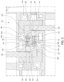
- the Figure 1 shows a device 10 for connecting high-voltage conductors.
- a device 10 for connecting high-voltage conductors.
- Such a device 10 is used, for example, in the field of electromobility.
- the device 10 has a total of three housing parts 12, 14 and 16, of which a first upper housing part 12 establishes the connection from the high-voltage supply lines 25 to the first high-voltage conductor 20.
- a second, middle housing part 14 forms first receiving spaces 143 for the vertical sections 22 of the first high-voltage conductor 20, second receiving spaces 142 for the second high-voltage conductors 30 and further receiving spaces 147 for connecting devices 40.
- the second receiving spaces 142 for the second high-voltage conductor 30 are L-shaped in cross-section. Immediately adjacent to the horizontal leg of the wall of the L-shaped cavity of the second receiving spaces 142, a first receiving space 143 adjoins at the top, into which a vertical section 22 of a first high-voltage conductor 20 opens from above.
- the vertical section 22 penetrates a recess 149 in an upper horizontal cover plate of the second housing part 14.
- the space between the first The partition wall of the housing part 14 located between the first receiving space 143 and the second receiving space 142 has a recess 1425 in the region of the vertical section 22 (see Figure 3 ). Through this recess 1425, the vertical section 22 of the first high-voltage conductor 20 and the second high-voltage conductor 30 come into direct contact with one another and are pressed together there by the pressure of a connecting device 40 described below.
- the housing part 14 Immediately adjacent to this contact area of the first high-voltage conductor 20, 22 and the second high-voltage conductor 30 or to the first receiving spaces 143, the housing part 14 has a further receiving space 147 for the connecting device 40 in a horizontal position.
- the connecting device 40 has a contact bolt 41, which is connected to a cylindrical or cuboid-shaped pressure piece 43 at its end facing the vertical section 22 of the first high-voltage conductor 20.
- the pressure piece 43 penetrates an opening between the receiving spaces 147 and 143, the shape of which is adapted to its cross section. The opening thus also serves to guide the pressure piece 43.
- the pressure piece 43 has a spherical cap-shaped or lens-shaped contour 44 on its front side facing the vertical section 22.
- the pressure piece 43 is acted upon on its other end by a first end of a spring 42 designed as a compression spring, which surrounds the contact bolt 41 and is supported with a second end on an abutment 148 delimiting the further receiving space 147.
- a spring 42 designed as a compression spring, which surrounds the contact bolt 41 and is supported with a second end on an abutment 148 delimiting the further receiving space 147.
- an adjusting device 45 which can be designed as an adjusting nut, for example, the preload of the spring 42 and/or the spring travel by which the pressure piece 43 can deviate against the pressure of the spring 42 can preferably be adjusted.
- the pressure piece 43 with its rounded contour 44 is pressed against the vertical section 22, whereby the first high-voltage conductor 20 comes into a conductive connection with the second high-voltage conductor 30.
- the contact force of the spring 42 is selected so that even high currents of more than 100 A at high voltages of, for example, 400 V, they can be transmitted reliably and largely without loss under all external conditions affecting a vehicle (vibrations, shocks, temperature fluctuations, humidity).
- the lower end of the vertical section 22 is preferably provided with a wedge-shaped bevel 23 on the surface facing the contour 44.
- This bevel 23 enables the vertical section 22 to be pushed into the receiving space 143 from above when the first high-voltage conductor 30 is already mounted, and the pressure piece 43 loaded by the spring 42 with its rounded contour 44 is pushed to the side accordingly.
- cooling channels 144 are provided adjacent to the receiving spaces 142 and 143 for the high-voltage conductors 22 and 30.
- a liquid coolant is pumped through the cooling channels 144, which serves to dissipate the heat that inevitably arises from the connection area of the high-voltage conductors 22 and 30 due to the transmission of high electrical power.
- the highly thermally conductive plastic consists of a polymer material with thermally conductive boron nitride fillers, in particular PA6, PA66, PBT, PPS, PEEK, LPS or TPE.
- thermally conductive boron nitride fillers in particular PA6, PA66, PBT, PPS, PEEK, LPS or TPE.
- Such a material can be obtained, for example, from 3M ® .
- cooling channels 144 can be connected to one another in a meandering manner by U-shaped connecting channels 151, wherein the connecting channels 151 are preferably arranged in a closing part 150, which tightly closes off the middle housing part 14, which is designed as an extruded profile 145, at least on one end face.
- the sealing is achieved either by a seal 155 cut out in the area of the cooling channels 144 or the connecting channels 151 or by a corresponding permanent bond at the same location.
- the upper, first housing part 12 and the middle, second housing part 14 are connected by Figure 1 shown connecting screws 18 and fastening devices 141 provided in the middle housing part 14.
- the fastening devices 141 can be formed by threads machined into the middle housing part 14.
- rectangular receiving channels for the positive reception of hexagon or square nuts with through holes arranged above them are also possible, through which the connecting screws 18 are screwed into the relevant nuts.
- the lower, third housing part 16 is connected by connecting screws 18A to fastening devices 141A on the middle housing part 14.
- several high-voltage conductors other than the two high-voltage conductors 20, 30 shown in the embodiment can also be connected by appropriate connecting devices 40. It is also possible to connect two or more high-voltage conductors 20, 30 lying one above the other by means of several connecting devices 40 arranged next to one another or one behind the other, in which case an even stronger connection of the high-voltage conductors is achieved by means of several contact forces generated by springs 42.
- the conductive connection can be easily established or broken without the use of tools.
Landscapes
- Engineering & Computer Science (AREA)
- Power Engineering (AREA)
- Transportation (AREA)
- Mechanical Engineering (AREA)
- Connector Housings Or Holding Contact Members (AREA)
Description
- Die Erfindung betrifft eine Vorrichtung zum Verbinden von Hochvoltleitern umfassend wenigstens einen ersten Hochvoltleiter, wenigstens einen zweiten Hochvoltleiter, eine Einrichtung zur Aufnahme des ersten und zweiten Hochvoltleiters und wenigstens eine Verbindungsvorrichtung zum stromleitenden Verbinden des wenigstens einen ersten Hochvoltleiters mit dem wenigstens einen zweiten Hochvoltleiter gemäß dem Oberbegriff des Patentanspruchs 1.
- Elektrische Verbindungen für eine Übertragung hoher elektrischer Leistungen werden bisher meistens als Schraubverbindungen ausgeführt. Derartige Verbindungen dürfen aus Sicherheitsgründen nur von entsprechend ausgebildetem und geprüftem Personal hergestellt bzw. wieder gelöst werden. In der Fertigung lassen sich die Anzugsmomente derartiger Schraubverbindungen und die davon abhängigen Übergangswiderstände zwischen den Hochvoltleitern prozesssicher überwachen. Bei einer Reparatur oder einem notwendigen Austausch von Komponenten in einer Werkstatt ist eine Verfügbarkeit von entsprechendem Personal nicht immer gegeben und eine prozesssichere Verbindung somit auch nicht immer gewährleistet. Somit besteht ein Bedürfnis nach einer Verbindungsvorrichtung für Hochvoltleiter, die ohne eine Schraubverbindung auskommt.
- Eine gattungsgemäße Vorrichtung ist aus der
DE 10 2012 201 124 A1 bekannt. Bei dieser weist eine zylindrische Verbindungsvorrichtung eine Vielzahl von längs verlaufenden Lamellen auf, die jeweils auf ihrer Innen-und Außenseite mit durch die Lamellen federnd gelagerten Kontakten versehen sind. -
EP0863522 A2 zeigt eine Notabschaltvorrichtung zum Verbinden von Hochvoltleitern umfassend wenigstens einen ersten Hochvoltleiter, wenigstens einen zweiten Hochvoltleiter, eine Einrichtung zur Aufnahme des ersten Hochvoltleiters und zweiten Hochvoltleiters und wenigstens eine Verbindungsvorrichtung zum stromleitenden Verbinden des wenigstens einen ersten Hochvoltleiters mit dem wenigstens einen zweiten Hochvoltleiter. Auch weist die Vorrichtung eine Druckfeder auf. - Aufgabe der Erfindung ist es, eine Vorrichtung zum Verbinden von Hochvoltleitern zu schaffen, mittels der wenigstens zwei Hochvoltleiter ohne Verwendung eines Werkzeugs prozesssicher verbunden und auch wieder voneinander getrennt werden können.
- Diese Aufgabe wird erfindungsgemäß durch eine Vorrichtung mit den Merkmalen des Anspruchs 1 gelöst. Vorteilhafte Ausgestaltungen der Erfindung sind in den Unteransprüchen angegeben.
- Ein bevorzugtes Einsatzgebiet der Erfindung sind Anwendungen im Automobilbereich, insbesondere Anwendungen in der Elektromobilität.
- Mit der vorliegenden Erfindung ist es möglich, eine prozesssichere Verbindung von Hochvoltleitern mit einer an die Übertragung der zwischen diesen fließenden Ströme bzw. übertragenen Leistungen anpassbaren Verbindungskraft zu erreichen, die noch dazu einfach zu bedienen ist.
- Die erfindungsgemäße Vorrichtung zum Verbinden von Hochvoltleitern umfasst wenigstens einen ersten Hochvoltleiter, wenigstens einen zweiten Hochvoltleiter, eine Einrichtung zur Aufnahme des ersten und zweiten Hochvoltleiters und wenigstens eine Verbindungsvorrichtung zum stromleitenden Verbinden des wenigstens einen ersten Hochvoltleiters mit dem wenigstens einen zweiten Hochvoltleiter. Erfindungsgemäß weist die Verbindungsvorrichtung wenigstens einen mittels wenigstens einer Feder vorgespannten Kontaktbolzen zum Zusammenpressen des wenigstens einen ersten Hochvoltleiters mit dem wenigstens einen zweiten Hochvoltleiter auf, wobei die Verbindungsvorrichtung wenigstens einen Aufnahmeraum für wenigstens einen der Hochvoltleiter und ein Widerlager für die Federn bildet.
- Durch die mittels der Federkennlinie und des beim Herstellen der Verbindung zurückgelegten Federweges wird eine eindeutige Anpresskraft definiert, die durch Veränderung dieser Parameter auch in einfacher Weise an unterschiedliche übertragende Ströme anpassbar ist.
- In einer vorteilhaften Ausführungsform der Erfindung weist die Einrichtung zur Aufnahme der Hochvoltleiter wenigstens einen ersten Aufnahmeraum für den ersten Hochvoltleiter und wenigstens einen zweiten Aufnahmeraum für den zweiten Hochvoltleiter auf, die einen gemeinsamen offenen Verbindungsbereich aufweisen, der eine unmittelbar berührende Anlage des ersten Hochvoltleiters und des zweiten Hochvoltleiter aneinander ermöglicht. Die Aufnahmeräume sind an die Kontur der Hochvoltleiter angepasst, die beispielsweise als im Querschnitt rechteckige Stromschienen ausgebildet und in einfacher Weise von außen in die Aufnahmeräume einschiebbar sind. Die Aufnahmeräume bewirken somit zum einen eine formschlüssige Lagerung der Hochvoltleiter zumindest in zwei Dimensionen und bilden zum anderen auch ein Widerlager gegen die von der Feder ausgeübte Druckkraft.
- Erfindungsgemäß ist vorgesehen, dass der Kontaktbolzen an einem Ende ein zur Anlage an einem der Hochvoltleiter geeignetes Druckstück aufweist. Dieses Druckstück weist besonders bevorzugt an seiner den Hochvoltleitern zugewandten Stirnseite eine kugelabschnittsförmige oder linsenförmige Kontur auf. Diese Kontur ermöglicht zum einen ein Ausweichen des Druckstücks gegen den Druck der Feder beim Einschieben eines Hochvoltleiters und zum anderen eine hohe punktförmig wirkende Anpresskraft des Druckstücks auf die beiden zusammen zu pressenden Hochvoltleiter. Bei Bedarf können auch mehrere nebeneinander oder hintereinander angeordnete Verbindungseinrichtungen zum Verbinden zweier oder mehrerer Hochvoltleiter vorgesehen sein. Gemäß einer weiteren besonders vorteilhaften Ausgestaltung der Erfindung ist vorgesehen, dass die Vorspannkraft der Feder mittels einer Einstellvorrichtung einstellbar ist. Dadurch ist die Vorrichtung in einfacher Weise an unterschiedlich dicke Hochvoltleiter oder an unterschiedliche Pakete aus mehreren übereinanderliegenden Hochvoltleitern und/oder an unterschiedlich starke zu übertragende Ströme bzw. elektrische Leistungen anpassbar.
- Vorteilhaft sind die Aufnahmeräume für die ersten und zweiten Hochvoltleiter und zumindest ein weiterer Aufnahmeraum für wenigstens eine Verbindungsvorrichtung in einem gemeinsamen Gehäuseteil der Vorrichtung angeordnet. Dies ermöglicht eine besonders kompakte Bauweise und eine Vormontage der Verbindungsvorrichtungen in diesem Gehäuseteil vor dessen Verbindung mit benachbarten Gehäuseteilen.
- Eine vorteilhafte Weiterentwicklung der Erfindung sieht vor, dass benachbart zu den Aufnahmeräumen für die Hochvoltleiter Kühlkanäle zur Führung eines insbesondere flüssigen Kühlmediums vorgesehen sind.
- Eine besonders kostengünstige Herstellung der erfindungsgemäßen Vorrichtung ergibt sich dadurch, dass das die Aufnahmeräume bildende gemeinsame Gehäuseteil als Strangpressprofil ausgebildet ist. Derartige Strangpressprofile können auch mit komplexen Konturen der Aufnahmeräume kostengünstig als Meterware hergestellt und durch Ablängen an beliebiger Stelle an unterschiedlich große benötigte Vorrichtungen angepasst werden.
- Besonders vorteilhaft ist es, wenn das Strangpressprofil aus einem hoch wärmeleitfähigen Kunststoff ausgebildet ist. Durch diese Materialauswahl werden mehrere Vorteile gleichzeitig erreicht:
- der Wärmeübergang von den Hochvoltleitern zu den Kühlkanälen funktioniert ausgezeichnet,
- komplexe Konturen der Aufnahmeräume sind in einem Extrusionswerkzeug für Kunststoff einfach darstellbar,
- die Vorrichtung ist gewichtssparend herstellbar, was insbesondere für eine Verwendung im Automobilbereich nützlich ist,
- der Kunststoff sorgt für eine hervorragende elektrische Isolierung der Hochvoltleiter gegenüber der Umgebung.
- Eine vorteilhafte Ergänzung der Erfindung sieht vor, dass wenigstens zwei Kühlkanäle durch wenigstens einen Verbindungskanal verbunden sind, der in zumindest einem an wenigstens eine Stirnseite des Strangpressprofils dicht angrenzenden Abschlussteil ausgebildet ist. Durch ein derartiges Abschlussteil mit darin integrierten Verbindungskanälen ist zum einen ein sauberer stirnseitiger Abschluss eines als Strangpressprofil hergestellten Gehäuseteils gewährleistet und wird zum anderen eine einfache mäanderförmige Verbindung und Führung eines Kühlmediums durch die Kühlkanäle möglich.
- Zwischen dem Abschlussteil und dem stirnseitigen Ende des Strangpressprofils ist bevorzugt eine Dichtung angeordnet, in der die Verbindungsbereiche zwischen den Kühlkanälen und den Verbindungskanälen entsprechend ausgespart sind. Anstelle einer Verbindung mittels einer Dichtung und einer Verschraubung kann das Abschlussteil auch dauerhaft mit der Stirnseite des Strangpressprofils dicht verklebt werden.
- Vorteilhaft weist das die Aufnahmeräume bildende Gehäuseteil Befestigungsvorrichtungen zur Verbindung mit wenigstens einem benachbarten Gehäuseteil auf. Diese können als senkrecht zur Extrusionsrichtung des Gehäuseteils eingebrachte Gewindebohrungen oder alternativ dazu als unmittelbar im Extrusionsverfahren mit geformte formschlüssige Aufnahmeräume für Sechskant- oder Vierkantmuttern ausgebildet sein.
- Das Einpressen eines Hochvoltleiters in die erfindungsgemäße Vorrichtung wird zusätzlich zur kugeligen oder linsenförmigen Kontur des Druckstücks dadurch erleichtert, dass der dem Kontaktbolzen bzw. dem Druckstück zugewandte Hochvoltleiter an einem Ende eine seine Dicke vermindernde, keilförmige Abschrägung aufweist.
- Nachfolgend wird ein Ausführungsbeispiel der Erfindung unter Bezugnahme auf die Zeichnungen näher erläutert. Es zeigt:
- Fig. 1
- eine seitlich aufgebrochene perspektivische Ansicht der erfindungsgemäßen Vorrichtung;
- Fig. 2
- einen vertikalen Teilschnitt durch die in einem mittleren Gehäuseteil angeordnete Einrichtung zur Aufnahme der Hochvoltleiter und der Verbindungsvorrichtungen;
- Fig. 3
- eine vergrößerte Teildarstellung aus
Figur 1 ; und - Fig. 4
- einen horizontalen Schnitt durch die Kühlkanäle des die Aufnahmeräume bildenden Gehäuseteils und das stirnseitig am Gehäuseteil angeordnete Abschlussteil mit den Verbindungskanälen.
- Die
Figur 1 zeigt eine Vorrichtung 10 zum Verbinden von Hochvoltleitern. Eine derartige Vorrichtung 10 kommt beispielsweise im Bereich der Elektromobilität zum Einsatz. Über Hochvolt-Zuleitungen 25 in die Vorrichtung 10 eingespeiste elektrische Energie, die beispielsweise von einem nicht dargestellten Batteriemodul geliefert wird, wird im Inneren der Vorrichtung 10 über eine erste Hochvoltleitung 20, die einen horizontalen Abschnitt 21 und vertikale Abschnitte 22 aufweist, in eine leitende Verbindung mit wenigstens einem zweiten Hochvoltleiter 30 gebracht. - Die Vorrichtung 10 weist insgesamt drei Gehäuseteile 12 ,14 und 16 auf, von denen ein erstes oberes Gehäuseteil 12 die Verbindung von den Hochvolt-Zuleitungen 25 zum ersten Hochvoltleiter 20 herstellt.
- Ein zweites, mittleres Gehäuseteil 14 bildet erste Aufnahmeräume 143 für die vertikalen Abschnitte 22 des ersten Hochvoltleiters 20, zweite Aufnahmeräume 142 für die zweiten Hochvoltleiter 30 und weitere Aufnahmeräume 147 für Verbindungsvorrichtungen 40.
- Die zweiten Aufnahmeräume 142 für den zweiten Hochvoltleiter 30 sind im Querschnitt L-förmig ausgebildet. Unmittelbar anschließend an den horizontalen Schenkel der Wandung des L-förmige Hohlraums der zweiten Aufnahmeräume 142 schließt sich nach oben ein erster Aufnahmeraum 143 an, in den von oben kommend ein vertikaler Abschnitt 22 eines ersten Hochvoltleiters 20 einmündet. Der vertikale Abschnitt 22 durchdringt dabei eine Aussparung 149 in einer oberen horizontalen Deckplatte des zweiten Gehäuseteils 14. Die zwischen dem ersten Aufnahmeraum 143 und dem zweiten Aufnahmeraum 142 liegende Trennwand des Gehäuseteils 14 weist im Bereich des vertikalen Abschnitts 22 eine Aussparung 1425 auf (siehe
Figur 3 ). Durch diese Aussparung 1425 gelangen der vertikale Abschnitt 22 des ersten Hochvoltleiters 20 und der zweite Hochvoltleiter 30 in unmittelbare Anlage aneinander und werden dort durch den Druck einer nachfolgend beschriebenen Verbindungsvorrichtung 40 zusammengepresst. - Unmittelbar benachbart zu diesem Anlagebereich des ersten Hochvoltleiters 20, 22 und des zweiten Hochvoltleiters 30 bzw. zu den ersten Aufnahmeräumen 143 weist das Gehäuseteil 14 in horizontaler Lage einen weiteren Aufnahmeraum 147 für die Verbindungsvorrichtung 40 auf. Die Verbindungsvorrichtung 40 weist einen Kontaktbolzen 41 auf, der an seinem dem vertikalen Abschnitt 22 des ersten Hochvoltleiters 20 zugewandten Ende mit einem zylindrischen oder Quader-förmigen Druckstück 43 verbunden ist. Das Druckstück 43 durchdringt einen in seiner Form an dessen Querschnitt angepassten Durchbruch zwischen den Aufnahmeräumen 147 und 143. Der Durchbruch dient somit auch zur Führung des Druckstücks 43.
- Das Druckstück 43 weist an seiner dem vertikalen Abschnitt 22 zugewandten Stirnseite eine Kugelkappen-förmige oder linsenförmige Kontur 44 auf.
- Das Druckstück 43 wird auf seiner anderen Stirnseite von einem ersten Ende einer als Druckfeder ausgebildeten Feder 42 beaufschlagt, die den Kontaktbolzen 41 umgibt und sich mit einem zweiten Ende an einem den weiteren Aufnahmeraum 147 begrenzenden Widerlager 148 abstützt. Mittels einer Einstellvorrichtung 45, die beispielsweise als Einstellmutter gebildet sein kann, kann die Vorspannung der Feder 42 und/oder der Federweg, um den das Druckstück 43 gegen den Druck der Feder 42 ausweichen kann, vorzugsweise angepasst werden.
- Mittels der Feder 42 wird das Druckstück 43 mit seiner gerundeten Kontur 44 gegen den vertikalen Abschnitt 22 gepresst, wodurch der erste Hochvoltleiter 20 in eine leitende Verbindung mit dem zweiten Hochvoltleiter 30 gerät. Die Anpresskraft der Feder 42 ist dabei so gewählt, dass auch hohe Ströme von mehr als 100 A bei hohen Spannungen von beispielsweise 400 V unter allen auf ein Fahrzeug einwirkenden äußeren Bedingungen (Schwingungen, Erschütterungen, Temperaturschwankungen, Feuchtigkeit) zuverlässig und weitestgehend verlustfrei übertragen werden.
- Das untere Ende des vertikalen Abschnitts 22 ist auf der der Kontur 44 zugewandten Fläche vorzugsweise mit einer keilförmigen Abschrägung 23 versehen. Diese Abschrägung 23 ermöglicht, dass der vertikale Abschnitt 22 bei bereits montiertem ersten Hochvoltleiter 30 von oben her in den Aufnahmeraum 143 eingeschoben werden kann und dabei das von der Feder 42 belastete Druckstück 43 mit seiner gerundeten Kontur 44 entsprechend zur Seite geschoben wird.
- Im mittleren Gehäuseteil 14 sind benachbart zu den Aufnahmeräumen 142 und 143 für die Hochvoltleiter 22 bzw. 30 mehrere Kühlkanäle 144 vorgesehen. Durch die Kühlkanäle 144 wird ein flüssiges Kühlmittel gepumpt, das zur Wärmeabfuhr der aufgrund der Übertragung hoher elektrischer Leistungen unvermeidbar entstehenden Wärme aus dem Verbindungsbereich der Hochvoltleiter 22 bzw. 30 dient.
- Das mittlere Gehäuseteil 14 ist besonders bevorzugt als Strangpressprofil 145 und dabei weiter bevorzugt insbesondere aus einem hoch wärmeleitfähigen Kunststoff hergestellt. Durch diese Materialauswahl werden mehrere Vorteile gleichzeitig erreicht:
- der Wärmeübergang von den Hochvoltleitern 20, 21, 22; 30 zu den Kühlkanälen 144 funktioniert ausgezeichnet,
- komplexe Konturen der Aufnahmeräume 142, 143, 147 sind in einem Extrusionswerkzeug für Kunststoff einfach darstellbar,
- die Vorrichtung 10 ist gewichtssparend herstellbar, was insbesondere für eine Verwendung im Automobilbereich nützlich ist,
- der Kunststoff sorgt für eine hervorragende elektrische Isolierung der Hochvoltleiter20, 21, 22; 30 gegenüber der Umgebung.
- Hierfür hat sich als besonders vorteilhaft erwiesen, dass der hoch wärmeleitfähige Kunststoff aus einem mit wärmeleitfähigen Bornitridfüllstoffen versehenen polymeren Werkstoff, insbesondere aus PA6, PA66, PBT, PPS, PEEK, LPS oder TPE besteht. Ein derartiger Werkstoff kann beispielsweise bei der Firma 3M® bezogen werden.
- Wie in
Figur 2 dargestellt, können mehrere Hochvoltleiter 20, 21, 22; 30 und mehrere Verbindungseinrichtungen 40 platzsparend durch eine gegenläufige nebeneinanderliegende Anordnung angeordnet werden. - Wie in
Figur 4 dargestellt, können mehrere Kühlkanäle 144 durch U-förmige Verbindungskanäle 151 mäanderförmig miteinander verbunden werden, wobei die Verbindungskanäle 151 bevorzugt in einem Abschlussteil 150 angeordnet sind, das stirnseitig das als Strangpressprofil 145 ausgebildete mittlere Gehäuseteil 14 zumindest an einer Stirnseite dicht abschließt. Die Abdichtung wird dabei entweder durch eine im Bereich der Kühlkanäle 144 bzw. der Verbindungskanäle 151 ausgesparte Dichtung 155 oder durch eine entsprechende dauerhafte Verklebung an gleicher Stelle bewirkt. - Das obere, erste Gehäuseteil 12 und das mittlere, zweite Gehäuseteil 14 sind durch in
Figur 1 gezeigte Verbindungsschrauben 18 und im mittleren Gehäuseteil 14 vorgesehene Befestigungsvorrichtungen 141 miteinander verbunden. Die Befestigungsvorrichtungen 141 können durch in das mittlere Gehäuseteil 14 eingearbeitete Gewinde gebildet sein. Alternativ dazu sind auch rechteckige Aufnahmekanäle zur formschlüssigen Aufnahme von Sechskant- oder Vierkantmuttern mit darüber angeordneten Durchgangsbohrungen möglich, durch welche die Verbindungsschrauben 18 in die betreffenden Muttern eingeschraubt werden. In gleicher Weise ist das untere, dritte Gehäuseteil 16 durch Verbindungsschrauben 18A mit Befestigungsvorrichtungen 141A am mittleren Gehäuseteil 14 verbunden. - In der erfindungsgemäßen Vorrichtung 10 können auch mehrere Hochvoltleiter als die im Ausführungsbeispiel gezeigten zwei Hochvoltleiter 20, 30 durch entsprechende Verbindungseinrichtungen 40 verbunden werden. Es ist ebenso möglich, zwei oder mehrere übereinander liegende Hochvoltleiter 20, 30 auch durch mehrere nebeneinander oder hintereinander angeordnete Verbindungseinrichtungen 40 zu verbinden, wobei dann durch mehrere durch Federn 42 erzeugte Anpresskräfte eine noch stärkere Verbindung der Hochvoltleiter erzielt wird.
- Durch das mögliche nachträgliche Einpressen oder Herausziehen des vertikalen Abschnitts 22 kann die leitende Verbindung ohne Verwendung von Werkzeugen in einfacher Weise hergestellt oder wieder aufgelöst werden.
-
- 10
- Vorrichtung
- 12
- (erstes) Gehäuseteil
- 14
- (zweites) Gehäuseteil
- 141, 141A
- Befestigungsvorrichtung (Gewinde oder Aufnahme für Mutter)
- 142
- (zweiter) Aufnahmeraum (für 30)
- 1425
- Aussparung (zwischen 142 und 143)
- 143
- (erster) Aufnahmeraum (für 20 bzw. 22)
- 144
- Kühlkanal
- 145
- Strangpressprofil
- 147
- (weiterer) Aufnahmeraum (für 40)
- 148
- Widerlager
- 149
- Durchbruch
- 150
- Abschlussteil
- 151
- Verbindungskanal (in 150)
- 155
- Dichtung
- 16
- (drittes) Gehäuseteil
- 18, 18A
- Verbindungsschraube
- 20
- (erster) Hochvoltleiter
- 21
- (horizontaler) Abschnitt (von 20)
- 22
- (vertikaler) Abschnitt (von 20)
- 23
- Abschrägung
- 25
- Hochvolt-Zuleitung
- 30
- (zweiter) Hochvoltleiter
- 40
- Verbindungsvorrichtung
- 41
- Kontaktbolzen
- 42
- Feder
- 43
- Druckstück
- 44
- (kugelabschnittsförmige oder linsenförmige) Kontur (an 43)
- 45
- Einstellvorrichtung (z.B. Einstellmutter)
Claims (12)
- Vorrichtung (10) zum Verbinden von Hochvoltleitern (20, 21, 22; 30) umfassend wenigstens einen ersten Hochvoltleiter (20, 21, 22), wenigstens einen zweiten Hochvoltleiter (30), eine Einrichtung (14) zur Aufnahme des ersten Hochvoltleiters (20, 21, 22) und zweiten Hochvoltleiters (30) und wenigstens eine Verbindungsvorrichtung (40) zum stromleitenden Verbinden des wenigstens einen ersten Hochvoltleiters (20, 21, 22) mit dem wenigstens einen zweiten Hochvoltleiter (30), wobei die Verbindungsvorrichtung (40) wenigstens einen mittels wenigstens einer Feder (42) vorgespannten Kontaktbolzen (41) zum Zusammenpressen des wenigstens einen ersten Hochvoltleiters (20, 21, 22) mit dem wenigstens einen zweiten Hochvoltleiter (30) aufweist, wobei die Verbindungsvorrichtung (40) wenigstens einen Aufnahmeraum (142, 143) für wenigstens einen der Hochvoltleiter (20, 21, 22; 30) und wenigstens ein Widerlager (148) für die Feder (42) bildet, wobei der Kontaktbolzen (41) an einem Ende ein zur Anlage an einem der Hochvoltleiter (20, 21, 22; 30) geeignetes Druckstück (43) aufweist.
- Vorrichtung (10) nach Anspruch 1, dadurch gekennzeichnet, dass die Einrichtung (14) einen ersten Aufnahmeraum (143) für den ersten Hochvoltleiter (20, 21, 22) und einen zweiten Aufnahmeraum (142) für den zweiten Hochvoltleiter (30) mit einem gemeinsamen offenen Verbindungsbereich aufweisen, der eine unmittelbar berührende Anlage des ersten Hochvoltleiters (20, 21, 22) und des zweiten Hochvoltleiters (30) aneinander ermöglicht.
- Vorrichtung (10) nach Anspruch 1 oder 2, dadurch gekennzeichnet, dass das Druckstück (43) an seiner den Hochvoltleitern (20, 21, 22; 30) zugewandten Stirnseite eine kugelabschnittsförmige oder linsenförmige Kontur (44) aufweist.
- Vorrichtung (10) nach einem der vorhergehenden Ansprüche, dadurch gekennzeichnet, dass die Vorspannkraft der Feder (42) mittels einer Einstellvorrichtung (45) einstellbar ist.
- Vorrichtung (10) nach einem der vorhergehenden Ansprüche, dadurch gekennzeichnet, dass die Aufnahmeräume (142, 143) für die Hochvoltleiter (20, 21, 22; 30) und ein weiterer Aufnahmeraum (147) für die Verbindungsvorrichtung (40) in einem gemeinsamen Gehäuseteil (14) der Vorrichtung (10) angeordnet sind.
- Vorrichtung (10) nach einem der vorhergehenden Ansprüche, dadurch gekennzeichnet, dass benachbart zu den Aufnahmeräumen (142, 143) für die Hochvoltleiter (20, 21, 22; 30) Kühlkanäle (144) zur Führung eines flüssigen Kühlmediums vorgesehen sind.
- Vorrichtung (10) nach Anspruch 5oder 6, dadurch gekennzeichnet, dass das Gehäuseteil (14) als Strangpressprofil (145) ausgebildet ist.
- Vorrichtung (10) nach Anspruch 7, dadurch gekennzeichnet, dass das Strangpressprofil (145) aus einem hoch wärmeleitfähigen Kunststoff ausgebildet ist.
- Vorrichtung (10) nach Anspruch 6 und 7 oder 6 und 8, dadurch gekennzeichnet, dass wenigstens zwei Kühlkanäle (144) durch wenigstens einen Verbindungskanal (151) verbunden sind, der in zumindest einem an wenigstens eine Stirnseite des Strangpressprofils (145) dicht angrenzenden Abschlussteil (150) ausgebildet ist.
- Vorrichtung (10) nach wenigstens einem der Ansprüche 5 bis 9, dadurch gekennzeichnet, dass das Gehäuseteil (14) Befestigungsvorrichtungen (141) zur Verbindung mit wenigstens einem benachbarten Gehäuseteil (12) aufweist.
- Vorrichtung (10) nach Anspruch 10, dadurch gekennzeichnet, dass die Befestigungsvorrichtungen (141) zur Aufnahme wenigstens eines Gewindes oder einer ein Gewinde aufweisenden Mutter ausgebildet sind.
- Vorrichtung (10) nach einem der vorhergehenden Ansprüche, dadurch gekennzeichnet, dass der dem Kontaktbolzen (141) zugewandte Hochvoltleiter (20, 21, 22) an einem Ende eine seine Dicke vermindernde Abschrägung (23) aufweist.
Applications Claiming Priority (2)
| Application Number | Priority Date | Filing Date | Title |
|---|---|---|---|
| DE102020109562.7A DE102020109562B4 (de) | 2020-04-06 | 2020-04-06 | Vorrichtung zum Verbinden von Hochvoltleitern |
| PCT/EP2021/058298 WO2021204595A1 (de) | 2020-04-06 | 2021-03-30 | Vorrichtung zum verbinden von hochvoltleitern |
Publications (3)
| Publication Number | Publication Date |
|---|---|
| EP4065408A1 EP4065408A1 (de) | 2022-10-05 |
| EP4065408C0 EP4065408C0 (de) | 2024-05-01 |
| EP4065408B1 true EP4065408B1 (de) | 2024-05-01 |
Family
ID=75377769
Family Applications (1)
| Application Number | Title | Priority Date | Filing Date |
|---|---|---|---|
| EP21716337.7A Active EP4065408B1 (de) | 2020-04-06 | 2021-03-30 | Vorrichtung zum verbinden von hochvoltleitern |
Country Status (3)
| Country | Link |
|---|---|
| EP (1) | EP4065408B1 (de) |
| DE (1) | DE102020109562B4 (de) |
| WO (1) | WO2021204595A1 (de) |
Families Citing this family (1)
| Publication number | Priority date | Publication date | Assignee | Title |
|---|---|---|---|---|
| CN115009069B (zh) * | 2022-07-05 | 2022-11-15 | 浙江电马云车科技有限公司 | 基于5g通讯微组网智能型充电桩 |
Citations (1)
| Publication number | Priority date | Publication date | Assignee | Title |
|---|---|---|---|---|
| EP0863522B1 (de) * | 1997-03-03 | 2005-09-14 | REMA Lipprandt GmbH & Co. KG | Notabschaltvorrichtung, insbesondere bei Elektro-Flurförderzeugen zum Trennen der Verbindung zwischen Motor oder dessen Steuereinheit und den Antriebsbatterien für diesen |
Family Cites Families (7)
| Publication number | Priority date | Publication date | Assignee | Title |
|---|---|---|---|---|
| US2010453A (en) | 1932-07-30 | 1935-08-06 | Harry A Douglas | Metallic connecter |
| DE1096993B (de) | 1956-04-12 | 1961-01-12 | Wago Klemmenwerk G M B H | Kabelschuh fuer elektrische Leiter zum Anschluss an Federdruck-Klemmen |
| US6854999B2 (en) | 2002-07-17 | 2005-02-15 | Tyco Electronics Corporation | Anti-overstress electrical connector |
| JP2006179368A (ja) | 2004-12-24 | 2006-07-06 | Kawamura Electric Inc | ねじ無し端子 |
| CN103098363A (zh) * | 2010-09-30 | 2013-05-08 | 日立汽车系统株式会社 | 电力转换装置 |
| DE102012201124B4 (de) | 2012-01-26 | 2020-03-26 | Lisa Dräxlmaier GmbH | Kontaktelement |
| DE102016225527A1 (de) | 2016-12-20 | 2018-06-21 | Bayerische Motoren Werke Aktiengesellschaft | Verbindungselement und Verbindungsvorrichtung zum elektrischen Verbinden eines Kabels mit einem elektrischen Gerät eines Kraftfahrzeugs |
-
2020
- 2020-04-06 DE DE102020109562.7A patent/DE102020109562B4/de not_active Expired - Fee Related
-
2021
- 2021-03-30 EP EP21716337.7A patent/EP4065408B1/de active Active
- 2021-03-30 WO PCT/EP2021/058298 patent/WO2021204595A1/de not_active Ceased
Patent Citations (1)
| Publication number | Priority date | Publication date | Assignee | Title |
|---|---|---|---|---|
| EP0863522B1 (de) * | 1997-03-03 | 2005-09-14 | REMA Lipprandt GmbH & Co. KG | Notabschaltvorrichtung, insbesondere bei Elektro-Flurförderzeugen zum Trennen der Verbindung zwischen Motor oder dessen Steuereinheit und den Antriebsbatterien für diesen |
Also Published As
| Publication number | Publication date |
|---|---|
| DE102020109562B4 (de) | 2024-04-11 |
| WO2021204595A1 (de) | 2021-10-14 |
| EP4065408C0 (de) | 2024-05-01 |
| DE102020109562A1 (de) | 2021-10-07 |
| EP4065408A1 (de) | 2022-10-05 |
Similar Documents
| Publication | Publication Date | Title |
|---|---|---|
| DE102012201123B3 (de) | Gewinkelter Hochvolt-Stecker | |
| EP2226899B1 (de) | Vorrichtung zum Verbinden von zwei elektrischen Leitern | |
| EP2440005A1 (de) | Elektrische Heizvorrichtung und Verfahren zur Herstellung | |
| EP3235067A1 (de) | Steckverbinder | |
| EP3588236B1 (de) | Gehäuse für ein elektronisches bauteil, herstellungsverfahren eines derartigen gehäuses und vorrichtung zur temperaturregelung mit einem derartigen gehäuse | |
| DE102007042589A1 (de) | Einrichtung zur kraftstoffdichten Durchführung von elektrischen Kontaktelementen durch eine Wandung, sowie derartiges Kontaktelement | |
| DE112009004685B4 (de) | Leiter einer elektrischen Hochspannungsvorrichtung | |
| DE102012105113A1 (de) | Durchführungsvorrichtung für ein explosionsgeschütztes Gehäuse | |
| DE202010017768U1 (de) | Kabelverbindungseinrichtung | |
| EP3485538B1 (de) | Verbindungselement | |
| DE102017200683B4 (de) | Temperatursensor für den Verdampfer einer Kraftfahrzeug-Klimaanlage | |
| DE102015110308B4 (de) | Akkupack für ein Elektrohandwerkzeuggerät | |
| EP3842187A1 (de) | Vorrichtung zur verbindung eines netzkabels | |
| EP4065408B1 (de) | Vorrichtung zum verbinden von hochvoltleitern | |
| DE102016118163A1 (de) | Lösbare verbindungseinrichtung für hohe ströme | |
| DE102020111359A1 (de) | Berührgeschützte Verbindungsanordnung von zwei elektrischen Leitern sowie Kraftfahrzeug mit einer solchen Verbindungsanordnung | |
| DE102015222190A1 (de) | Steckverbinder und Motor- oder Ventilabdeckungselement umfassend einen Steckverbinder | |
| DE102013013368A1 (de) | Verfahren zur Herstellung einer elektrischen Verbindung sowie elektrische Verbindung | |
| EP4143864A1 (de) | Elektrische sicherungsvorrichtung, verfahren zur herstellung einer sicherungsvorrichtung und ein verfahren zum betrieb einer elektrischen sicherungsvorrichtung | |
| EP2740181A1 (de) | Steckverbinder für elektrische komponenten in kraftfahrzeugen | |
| DE102005012441A1 (de) | Elektrischer Steckverbinder sowie Verfahren zur Herstellung eines elektrischen Steckverbinders | |
| EP4132814A1 (de) | Vorrichtung zum verbinden von hochvoltleitern | |
| DE102015218747A1 (de) | HV-Kabel-Anschlussanordnung | |
| EP3837740B1 (de) | Steckverbinder | |
| DE102018211365B3 (de) | Fixierungsvorrichtung für ein Hochvoltbordnetz eines Kraftfahrzeugs, Hochvoltbordnetz Kraftfahrzeug sowie Verfahren |
Legal Events
| Date | Code | Title | Description |
|---|---|---|---|
| STAA | Information on the status of an ep patent application or granted ep patent |
Free format text: STATUS: UNKNOWN |
|
| STAA | Information on the status of an ep patent application or granted ep patent |
Free format text: STATUS: THE INTERNATIONAL PUBLICATION HAS BEEN MADE |
|
| PUAI | Public reference made under article 153(3) epc to a published international application that has entered the european phase |
Free format text: ORIGINAL CODE: 0009012 |
|
| STAA | Information on the status of an ep patent application or granted ep patent |
Free format text: STATUS: REQUEST FOR EXAMINATION WAS MADE |
|
| 17P | Request for examination filed |
Effective date: 20220629 |
|
| AK | Designated contracting states |
Kind code of ref document: A1 Designated state(s): AL AT BE BG CH CY CZ DE DK EE ES FI FR GB GR HR HU IE IS IT LI LT LU LV MC MK MT NL NO PL PT RO RS SE SI SK SM TR |
|
| DAV | Request for validation of the european patent (deleted) | ||
| DAX | Request for extension of the european patent (deleted) | ||
| GRAP | Despatch of communication of intention to grant a patent |
Free format text: ORIGINAL CODE: EPIDOSNIGR1 |
|
| STAA | Information on the status of an ep patent application or granted ep patent |
Free format text: STATUS: GRANT OF PATENT IS INTENDED |
|
| INTG | Intention to grant announced |
Effective date: 20231120 |
|
| GRAS | Grant fee paid |
Free format text: ORIGINAL CODE: EPIDOSNIGR3 |
|
| GRAA | (expected) grant |
Free format text: ORIGINAL CODE: 0009210 |
|
| STAA | Information on the status of an ep patent application or granted ep patent |
Free format text: STATUS: THE PATENT HAS BEEN GRANTED |
|
| AK | Designated contracting states |
Kind code of ref document: B1 Designated state(s): AL AT BE BG CH CY CZ DE DK EE ES FI FR GB GR HR HU IE IS IT LI LT LU LV MC MK MT NL NO PL PT RO RS SE SI SK SM TR |
|
| REG | Reference to a national code |
Ref country code: GB Ref legal event code: FG4D Free format text: NOT ENGLISH |
|
| REG | Reference to a national code |
Ref country code: CH Ref legal event code: EP |
|
| REG | Reference to a national code |
Ref country code: IE Ref legal event code: FG4D Free format text: LANGUAGE OF EP DOCUMENT: GERMAN |
|
| REG | Reference to a national code |
Ref country code: DE Ref legal event code: R096 Ref document number: 502021003580 Country of ref document: DE |
|
| U01 | Request for unitary effect filed |
Effective date: 20240507 |
|
| U07 | Unitary effect registered |
Designated state(s): AT BE BG DE DK EE FI FR IT LT LU LV MT NL PT SE SI Effective date: 20240521 |
|
| PG25 | Lapsed in a contracting state [announced via postgrant information from national office to epo] |
Ref country code: IS Free format text: LAPSE BECAUSE OF FAILURE TO SUBMIT A TRANSLATION OF THE DESCRIPTION OR TO PAY THE FEE WITHIN THE PRESCRIBED TIME-LIMIT Effective date: 20240901 |
|
| PG25 | Lapsed in a contracting state [announced via postgrant information from national office to epo] |
Ref country code: HR Free format text: LAPSE BECAUSE OF FAILURE TO SUBMIT A TRANSLATION OF THE DESCRIPTION OR TO PAY THE FEE WITHIN THE PRESCRIBED TIME-LIMIT Effective date: 20240501 |
|
| PG25 | Lapsed in a contracting state [announced via postgrant information from national office to epo] |
Ref country code: GR Free format text: LAPSE BECAUSE OF FAILURE TO SUBMIT A TRANSLATION OF THE DESCRIPTION OR TO PAY THE FEE WITHIN THE PRESCRIBED TIME-LIMIT Effective date: 20240802 |
|
| PG25 | Lapsed in a contracting state [announced via postgrant information from national office to epo] |
Ref country code: ES Free format text: LAPSE BECAUSE OF FAILURE TO SUBMIT A TRANSLATION OF THE DESCRIPTION OR TO PAY THE FEE WITHIN THE PRESCRIBED TIME-LIMIT Effective date: 20240501 |
|
| PG25 | Lapsed in a contracting state [announced via postgrant information from national office to epo] |
Ref country code: PL Free format text: LAPSE BECAUSE OF FAILURE TO SUBMIT A TRANSLATION OF THE DESCRIPTION OR TO PAY THE FEE WITHIN THE PRESCRIBED TIME-LIMIT Effective date: 20240501 |
|
| PG25 | Lapsed in a contracting state [announced via postgrant information from national office to epo] |
Ref country code: PL Free format text: LAPSE BECAUSE OF FAILURE TO SUBMIT A TRANSLATION OF THE DESCRIPTION OR TO PAY THE FEE WITHIN THE PRESCRIBED TIME-LIMIT Effective date: 20240501 Ref country code: NO Free format text: LAPSE BECAUSE OF FAILURE TO SUBMIT A TRANSLATION OF THE DESCRIPTION OR TO PAY THE FEE WITHIN THE PRESCRIBED TIME-LIMIT Effective date: 20240801 Ref country code: IS Free format text: LAPSE BECAUSE OF FAILURE TO SUBMIT A TRANSLATION OF THE DESCRIPTION OR TO PAY THE FEE WITHIN THE PRESCRIBED TIME-LIMIT Effective date: 20240901 Ref country code: HR Free format text: LAPSE BECAUSE OF FAILURE TO SUBMIT A TRANSLATION OF THE DESCRIPTION OR TO PAY THE FEE WITHIN THE PRESCRIBED TIME-LIMIT Effective date: 20240501 Ref country code: GR Free format text: LAPSE BECAUSE OF FAILURE TO SUBMIT A TRANSLATION OF THE DESCRIPTION OR TO PAY THE FEE WITHIN THE PRESCRIBED TIME-LIMIT Effective date: 20240802 Ref country code: ES Free format text: LAPSE BECAUSE OF FAILURE TO SUBMIT A TRANSLATION OF THE DESCRIPTION OR TO PAY THE FEE WITHIN THE PRESCRIBED TIME-LIMIT Effective date: 20240501 Ref country code: RS Free format text: LAPSE BECAUSE OF FAILURE TO SUBMIT A TRANSLATION OF THE DESCRIPTION OR TO PAY THE FEE WITHIN THE PRESCRIBED TIME-LIMIT Effective date: 20240801 |
|
| PG25 | Lapsed in a contracting state [announced via postgrant information from national office to epo] |
Ref country code: CZ Free format text: LAPSE BECAUSE OF FAILURE TO SUBMIT A TRANSLATION OF THE DESCRIPTION OR TO PAY THE FEE WITHIN THE PRESCRIBED TIME-LIMIT Effective date: 20240501 |
|
| PG25 | Lapsed in a contracting state [announced via postgrant information from national office to epo] |
Ref country code: SK Free format text: LAPSE BECAUSE OF FAILURE TO SUBMIT A TRANSLATION OF THE DESCRIPTION OR TO PAY THE FEE WITHIN THE PRESCRIBED TIME-LIMIT Effective date: 20240501 Ref country code: RO Free format text: LAPSE BECAUSE OF FAILURE TO SUBMIT A TRANSLATION OF THE DESCRIPTION OR TO PAY THE FEE WITHIN THE PRESCRIBED TIME-LIMIT Effective date: 20240501 |
|
| PG25 | Lapsed in a contracting state [announced via postgrant information from national office to epo] |
Ref country code: SM Free format text: LAPSE BECAUSE OF FAILURE TO SUBMIT A TRANSLATION OF THE DESCRIPTION OR TO PAY THE FEE WITHIN THE PRESCRIBED TIME-LIMIT Effective date: 20240501 |
|
| PG25 | Lapsed in a contracting state [announced via postgrant information from national office to epo] |
Ref country code: SM Free format text: LAPSE BECAUSE OF FAILURE TO SUBMIT A TRANSLATION OF THE DESCRIPTION OR TO PAY THE FEE WITHIN THE PRESCRIBED TIME-LIMIT Effective date: 20240501 Ref country code: SK Free format text: LAPSE BECAUSE OF FAILURE TO SUBMIT A TRANSLATION OF THE DESCRIPTION OR TO PAY THE FEE WITHIN THE PRESCRIBED TIME-LIMIT Effective date: 20240501 Ref country code: RO Free format text: LAPSE BECAUSE OF FAILURE TO SUBMIT A TRANSLATION OF THE DESCRIPTION OR TO PAY THE FEE WITHIN THE PRESCRIBED TIME-LIMIT Effective date: 20240501 Ref country code: CZ Free format text: LAPSE BECAUSE OF FAILURE TO SUBMIT A TRANSLATION OF THE DESCRIPTION OR TO PAY THE FEE WITHIN THE PRESCRIBED TIME-LIMIT Effective date: 20240501 |
|
| REG | Reference to a national code |
Ref country code: DE Ref legal event code: R097 Ref document number: 502021003580 Country of ref document: DE |
|
| PLBE | No opposition filed within time limit |
Free format text: ORIGINAL CODE: 0009261 |
|
| STAA | Information on the status of an ep patent application or granted ep patent |
Free format text: STATUS: NO OPPOSITION FILED WITHIN TIME LIMIT |
|
| 26N | No opposition filed |
Effective date: 20250204 |
|
| PG25 | Lapsed in a contracting state [announced via postgrant information from national office to epo] |
Ref country code: MC Free format text: LAPSE BECAUSE OF FAILURE TO SUBMIT A TRANSLATION OF THE DESCRIPTION OR TO PAY THE FEE WITHIN THE PRESCRIBED TIME-LIMIT Effective date: 20240501 |
|
| REG | Reference to a national code |
Ref country code: CH Ref legal event code: H13 Free format text: ST27 STATUS EVENT CODE: U-0-0-H10-H13 (AS PROVIDED BY THE NATIONAL OFFICE) Effective date: 20251023 |
|
| U90 | Renewal fees not paid: noting of loss of rights |
Free format text: RENEWAL FEE NOT PAID FOR YEAR 05 Effective date: 20251015 |
|
| GBPC | Gb: european patent ceased through non-payment of renewal fee |
Effective date: 20250330 |
|
| PG25 | Lapsed in a contracting state [announced via postgrant information from national office to epo] |
Ref country code: GB Free format text: LAPSE BECAUSE OF NON-PAYMENT OF DUE FEES Effective date: 20250330 |
|
| PG25 | Lapsed in a contracting state [announced via postgrant information from national office to epo] |
Ref country code: CH Free format text: LAPSE BECAUSE OF NON-PAYMENT OF DUE FEES Effective date: 20250331 |
|
| PG25 | Lapsed in a contracting state [announced via postgrant information from national office to epo] |
Ref country code: IE Free format text: LAPSE BECAUSE OF NON-PAYMENT OF DUE FEES Effective date: 20250330 |
|
| U93 | Unitary patent lapsed |
Free format text: RENEWAL FEE NOT PAID Effective date: 20250331 |